EP4521155A1 - Optical device and photographing device comprising same - Google Patents
Optical device and photographing device comprising same Download PDFInfo
- Publication number
- EP4521155A1 EP4521155A1 EP22940574.1A EP22940574A EP4521155A1 EP 4521155 A1 EP4521155 A1 EP 4521155A1 EP 22940574 A EP22940574 A EP 22940574A EP 4521155 A1 EP4521155 A1 EP 4521155A1
- Authority
- EP
- European Patent Office
- Prior art keywords
- optical system
- lens group
- lens
- refractive power
- focusing
- Prior art date
- Legal status (The legal status is an assumption and is not a legal conclusion. Google has not performed a legal analysis and makes no representation as to the accuracy of the status listed.)
- Pending
Links
Images








Classifications
-
- G—PHYSICS
- G02—OPTICS
- G02B—OPTICAL ELEMENTS, SYSTEMS OR APPARATUS
- G02B15/00—Optical objectives with means for varying the magnification
- G02B15/14—Optical objectives with means for varying the magnification by axial movement of one or more lenses or groups of lenses relative to the image plane for continuously varying the equivalent focal length of the objective
- G02B15/143—Optical objectives with means for varying the magnification by axial movement of one or more lenses or groups of lenses relative to the image plane for continuously varying the equivalent focal length of the objective having three groups only
- G02B15/1431—Optical objectives with means for varying the magnification by axial movement of one or more lenses or groups of lenses relative to the image plane for continuously varying the equivalent focal length of the objective having three groups only the first group being positive
-
- G—PHYSICS
- G02—OPTICS
- G02B—OPTICAL ELEMENTS, SYSTEMS OR APPARATUS
- G02B13/00—Optical objectives specially designed for the purposes specified below
- G02B13/001—Miniaturised objectives for electronic devices, e.g. portable telephones, webcams, PDAs, small digital cameras
- G02B13/009—Miniaturised objectives for electronic devices, e.g. portable telephones, webcams, PDAs, small digital cameras having zoom function
-
- G—PHYSICS
- G02—OPTICS
- G02B—OPTICAL ELEMENTS, SYSTEMS OR APPARATUS
- G02B9/00—Optical objectives characterised both by the number of the components and their arrangements according to their sign, i.e. + or -
- G02B9/64—Optical objectives characterised both by the number of the components and their arrangements according to their sign, i.e. + or - having more than six components
-
- G—PHYSICS
- G02—OPTICS
- G02B—OPTICAL ELEMENTS, SYSTEMS OR APPARATUS
- G02B13/00—Optical objectives specially designed for the purposes specified below
- G02B13/001—Miniaturised objectives for electronic devices, e.g. portable telephones, webcams, PDAs, small digital cameras
- G02B13/0015—Miniaturised objectives for electronic devices, e.g. portable telephones, webcams, PDAs, small digital cameras characterised by the lens design
- G02B13/002—Miniaturised objectives for electronic devices, e.g. portable telephones, webcams, PDAs, small digital cameras characterised by the lens design having at least one aspherical surface
- G02B13/0045—Miniaturised objectives for electronic devices, e.g. portable telephones, webcams, PDAs, small digital cameras characterised by the lens design having at least one aspherical surface having five or more lenses
-
- G—PHYSICS
- G02—OPTICS
- G02B—OPTICAL ELEMENTS, SYSTEMS OR APPARATUS
- G02B13/00—Optical objectives specially designed for the purposes specified below
- G02B13/001—Miniaturised objectives for electronic devices, e.g. portable telephones, webcams, PDAs, small digital cameras
- G02B13/0055—Miniaturised objectives for electronic devices, e.g. portable telephones, webcams, PDAs, small digital cameras employing a special optical element
- G02B13/0065—Miniaturised objectives for electronic devices, e.g. portable telephones, webcams, PDAs, small digital cameras employing a special optical element having a beam-folding prism or mirror
-
- G—PHYSICS
- G02—OPTICS
- G02B—OPTICAL ELEMENTS, SYSTEMS OR APPARATUS
- G02B13/00—Optical objectives specially designed for the purposes specified below
- G02B13/02—Telephoto objectives, i.e. systems of the type + - in which the distance from the front vertex to the image plane is less than the equivalent focal length
-
- G—PHYSICS
- G02—OPTICS
- G02B—OPTICAL ELEMENTS, SYSTEMS OR APPARATUS
- G02B15/00—Optical objectives with means for varying the magnification
- G02B15/14—Optical objectives with means for varying the magnification by axial movement of one or more lenses or groups of lenses relative to the image plane for continuously varying the equivalent focal length of the objective
- G02B15/143—Optical objectives with means for varying the magnification by axial movement of one or more lenses or groups of lenses relative to the image plane for continuously varying the equivalent focal length of the objective having three groups only
- G02B15/1431—Optical objectives with means for varying the magnification by axial movement of one or more lenses or groups of lenses relative to the image plane for continuously varying the equivalent focal length of the objective having three groups only the first group being positive
- G02B15/143101—Optical objectives with means for varying the magnification by axial movement of one or more lenses or groups of lenses relative to the image plane for continuously varying the equivalent focal length of the objective having three groups only the first group being positive arranged +--
-
- G—PHYSICS
- G02—OPTICS
- G02B—OPTICAL ELEMENTS, SYSTEMS OR APPARATUS
- G02B15/00—Optical objectives with means for varying the magnification
- G02B15/14—Optical objectives with means for varying the magnification by axial movement of one or more lenses or groups of lenses relative to the image plane for continuously varying the equivalent focal length of the objective
- G02B15/16—Optical objectives with means for varying the magnification by axial movement of one or more lenses or groups of lenses relative to the image plane for continuously varying the equivalent focal length of the objective with interdependent non-linearly related movements between one lens or lens group, and another lens or lens group
- G02B15/163—Optical objectives with means for varying the magnification by axial movement of one or more lenses or groups of lenses relative to the image plane for continuously varying the equivalent focal length of the objective with interdependent non-linearly related movements between one lens or lens group, and another lens or lens group having a first movable lens or lens group and a second movable lens or lens group, both in front of a fixed lens or lens group
- G02B15/167—Optical objectives with means for varying the magnification by axial movement of one or more lenses or groups of lenses relative to the image plane for continuously varying the equivalent focal length of the objective with interdependent non-linearly related movements between one lens or lens group, and another lens or lens group having a first movable lens or lens group and a second movable lens or lens group, both in front of a fixed lens or lens group having an additional fixed front lens or group of lenses
- G02B15/17—Optical objectives with means for varying the magnification by axial movement of one or more lenses or groups of lenses relative to the image plane for continuously varying the equivalent focal length of the objective with interdependent non-linearly related movements between one lens or lens group, and another lens or lens group having a first movable lens or lens group and a second movable lens or lens group, both in front of a fixed lens or lens group having an additional fixed front lens or group of lenses arranged +--
-
- G—PHYSICS
- G02—OPTICS
- G02B—OPTICAL ELEMENTS, SYSTEMS OR APPARATUS
- G02B15/00—Optical objectives with means for varying the magnification
- G02B15/14—Optical objectives with means for varying the magnification by axial movement of one or more lenses or groups of lenses relative to the image plane for continuously varying the equivalent focal length of the objective
- G02B15/22—Optical objectives with means for varying the magnification by axial movement of one or more lenses or groups of lenses relative to the image plane for continuously varying the equivalent focal length of the objective with movable lens means specially adapted for focusing at close distances
-
- H—ELECTRICITY
- H04—ELECTRIC COMMUNICATION TECHNIQUE
- H04N—PICTORIAL COMMUNICATION, e.g. TELEVISION
- H04N23/00—Cameras or camera modules comprising electronic image sensors; Control thereof
- H04N23/50—Constructional details
- H04N23/55—Optical parts specially adapted for electronic image sensors; Mounting thereof
Definitions
- the invention relates to an optical system having a plurality of lens groups and a photographing device having the optical system.
- optical systems having a first lens group having a positive refractive power, a second lens group having a negative refractive power and a third lens group sequentially arranged from an object side to an image side, with only the second lens group moving along the optical axis during focusing have been known as optical systems described in patent document 1 ( Japanese patent communique No.5749629 ) and patent document 2 ( Japanese special publication communiqué No. 2021-173847 ).
- the optical system described in patent document 1 is not sufficient for close-range photographing, and the optical system described in patent document 2 is not sufficiently miniaturized because a ratio of total lengths of the optical system and the focal length is large.
- Patent documents are:
- the target of the present invention is to provide an optical system, which is miniaturized and capable of photographing at a close range, and a photographing device having the optical system.
- the optical system of the present invention includes:
- the second lens group includes:
- the photographing device of the present invention includes:
- a photographing device 1 includes an optical system 2, a photographing element 3 arranged at a position of an imaging plane of the optical system 2, and a liquid crystal screen 4 for displaying the photographing (image) data transmitted from a photographing element 3.
- the photographing device 1 includes a driving part (not shown in the figures) for driving the optical system 2.
- the driving part is an actuator such as a VCM (Voice Coil Motor), to drive a predetermined lens or lens group and the like included in the optical system 2 in a direction substantially perpendicular to a light receiving surface of the photographing element 3 (a direction of an optical axis).
- the photographing element 3 is an element that converts an optical image formed by the optical system 2 into an electrical signal (photographing data), and the photographing element 3 of the present embodiment is a CMOS image sensor.
- the optical system 2 is a so-called internal focusing optical system, and the optical system 2 of the present embodiment is a so-called periscope telephoto lens in which the optical axis (an optical path) C is bent by a reflective optical element such as a prism or a mirror.
- the optical system 2 includes a prism 20 that bends the optical axis C and a plurality of lens groups G arranged on the optical axis C sequentially from the object side to the image side along the optical axis C.
- the optical system 2 includes an aperture diaphragm 24, an optical filter 25 arranged between the plurality of lens groups G and the photographing element 3, and a lens barrel 26 holding the plurality of lens groups G.
- the plurality of lens groups G at least include a first lens group 21, a second lens group 22, and a third lens group 23 sequentially from the object side to the image side along the optical axis C.
- Each of the lens groups 21, 22 and 23 includes at least one lens (optical element).
- the lens groups 21 to 23 are named for convenience, and include a lens group composed of only one optical element (lens, etc.). That is, the first to third lens groups 21, 22 and 23 each have at least one optical element such as a lens.
- the optical elements (lenses, etc.) whose positions are fixed on the optical axis C during focusing are separated from the moving optical elements, and the at least one fixed optical element in a separated area is regarded as one lens group, and the at least one moving optical element in a separated area is regarded as another lens group.
- the second lens group 22 moves along the optical axis C, and positions of the first lens group 21 and the third lens group 23 in the direction of the optical axis C are fixed relative to the photographing element 3 (the imaging plane of the optical system 2). That is, in the optical system 2 of the present embodiment, among the lens groups 21, 22 and 23, the second lens group 22 constitutes a focusing lens group F.
- the first lens group 21 includes a plurality of lenses (four lenses in an example of the present embodiment) having a positive refractive power.
- the second lens group 22 includes a plurality of lenses (two lenses in an example of the present embodiment) having a negative bending rate.
- the third lens group 23 includes a plurality of lenses (two lenses in an example of the present embodiment) having a negative refractive power.
- the optical system 2 When a distance from a face closest to the object side to a face closest to the image side of the second lens group 22 is OAL2 and a distance from a face closest to the object side of the entire optical system 2 to the imaging plane is OAL, the optical system 2 satisfies the following formula (1). 0.06 ⁇ OAL 2 / OAL
- the first lens group 21 having the positive refractive power is arranged closest to the object side
- the second lens group 22 having the negative refractive power is arranged at the image side of the first lens group 21
- the third lens group 23 having the negative refractive power is arranged closest to the image side.
- the aberration variation balance with the front and rear lens groups 21, 23 may be adjusted. Bending variation of the imaging plane during close range photographing may be suppressed compared with a whole extension mode, so that the close range photographing distance may be further shortened.
- the second lens group 22 is set as a movable lens group, so that a load on a mechanism or actuator may be reduced, and therefore, the overall miniaturization of the photographing device 1 including the optical system 2 may be realized.
- the above formula (1) specifies a ratio (OAL2/OAL) of the distance from the face closest to the object side to the face closest to the image side of the second lens group 22 to the distance from the face closest to the object side of the entire optical system 2 to the imaging plane.
- a ratio (OAL2/OAL) is lower than a lower limit value (0.06), the aberration correction in the entire focus area becomes insufficient and the imaging performance becomes insufficient.
- the optical system 2 of the present embodiment by setting the ratio (OAL2/OAL) of the distance from the face closest to the object side to the face closest to the image side of the second lens group 22 to the distance from the face closest to the object side of the entire optical system 2 to the imaging plane within the range of formula (1), it is possible to perform sufficient aberration correction in the entire focused area, thereby ensuring sufficient imaging performance.
- the above ratio (OAL2/OAL) preferably satisfies the following formula. 0.11 ⁇ OAL 2 / OAL ⁇ 0.30
- the second lens group 22 has at least one lens having a positive refractive power and at least one lens having a negative refractive power.
- a lens 221 having the strongest positive refractive power may be arranged at a position closer to the image side than a lens 222 having the strongest negative refractive power.
- aberration correction may be achieved in the entire focus area from infinity photographing to close range photographing just by moving the second lens group 22.
- the details are as follows.
- an on-axis light beam that is strongly converged by the first lens group 21 on the object side of the second lens group 22 is regarded as a properly converged light beam, and a negative focal power is needed to make a peripheral light beam jump up and be guided to the image side of the second lens group 22.
- a positive focal power is required for convergence to obtain a desired F number.
- the second lens group 22 has at least one lens having a positive refractive power and at least one lens having a negative refractive power.
- the optical system 2 when a focal length of the entire optical system focusing at infinity is f, the optical system 2 may satisfy the following formula (2). OAL / f ⁇ 2.00
- the above formula (2) specifies a ratio (OAL/f) of the distance from the face closest to the object side of the entire optical system to the imaging plane to the focal length, and when the ratio (OAL/f) exceeds an upper limit (2.00), it cannot be said that a total optical length is sufficiently shortened, and not only the optical system 2, but also the entire photographing device 1 having the optical system 2 cannot be miniaturized.
- the total optical length may be sufficiently shortened, and thus, not only the optical system 2 may be miniaturized, but also the entire photographing device 1 having the optical system 2 may be miniaturized.
- the above ratio (OAL/f) preferably satisfies the following formula. 0.80 ⁇ OAL / f ⁇ 1.50
- the optical system 2 when a maximum lateral magnification of the entire optical system is B, the optical system 2 may also satisfy the following formula (3). 0.50 ⁇ B
- the above formula (3) specifies the maximum lateral magnification of the entire optical system, and when the value is lower than a lower limit (0.50), it cannot be said that close range photographing is fully realized, and a distance from the object that may be photographed cannot be shortened. Therefore, in the optical system 2 of the present embodiment, by setting the maximum lateral magnification of the entire optical system within a range of formula (3), the distance from the object that may be photographed may be shortened, and thus, an optical system 2 that is miniaturized and capable of photographing at a close range and a photographing device 1 having the optical system 2 may be realized.
- the maximum lateral magnification is a numerical value indicating a degree of close range photographing, which is a ratio of a height of the image on a photographing surface to a height of the object of the subject. For example, when photographing at a close range and
- the maximum lateral magnification of the entire optical system preferably satisfies the following formula. 0.75 ⁇ B .
- the optical system 2 when a lateral magnification of the second lens group focusing at infinity is b2 and a lateral magnification of the third lens group focusing at infinity is b3, the optical system 2 may also satisfy the following formula (4). ⁇ 10.00 ⁇ 1 ⁇ b2 2 ⁇ b3 2 ⁇ ⁇ 2.00
- the above formula (4) specifies a ratio ((1-b2 2 ) ⁇ b3 2 ) of a movement amount of the imaging plane to a movement amount of the second lens group 22 in the direction of the optical axis C.
- the numerical value corresponding to this formula is 1.
- this ratio by increasing this ratio with a negative value, the close range photographing may be realized with a small movement amount, and the miniaturization of the entire optical system 2 is realized.
- the ratio ((1-b2 2 ) ⁇ b3 2 ) is less than a lower limit (-10.00), the movement amount of the imaging plane relative to the movement amount of the second lens group 22 in the direction of the optical axis C becomes too large to improve accuracy of the stop position of the second lens group 22 by a driving device such as an actuator.
- the ratio ((1-b2 2 ) ⁇ b3 2 ) exceeds an upper limit (-2.00)
- the movement amount of the second lens group 22 for the close range photographing increases, so it is difficult to realize the miniaturization of the entire optical system 2.
- the optical system 2 of the present embodiment by setting the ratio ((1-b2 2 ) ⁇ b3 2 ) of the movement amount of the imaging plane to the movement amount of the second lens group 22 in the direction of the optical axis C within a range of the above-mentioned formula (4), it is possible to achieve a balance between improving the accuracy of the stop position of the second lens group 22 by an actuator or the like during focusing and the miniaturization of the entire optical system 2.
- the above ratio ((1-b2 2 ) ⁇ b3 2 ) preferably satisfies the following formula. ⁇ 9.00 ⁇ 1 ⁇ b2 2 ⁇ b 3 2 ⁇ ⁇ 2.50
- the optical system 2 when a focal length of the entire optical system focusing at infinity is f and a focal length of the above-mentioned second lens group is f2, the optical system 2 may also satisfy the following formula (5). ⁇ 0.70 ⁇ f2 / f ⁇ ⁇ 0.10
- the above formula (5) specifies a ratio (f2/f) of the focal length of the second lens group 22 to the focal length of the entire optical system 2 focusing at infinity.
- this ratio (f2/f) is lower than a lower limit (-0.70)
- the optical power of the second lens group 22 becomes weak, and the movement amount of the second lens group 22 for the close range photographing becomes large, so it is difficult to realize the miniaturization of the entire optical system 2.
- the ratio (f2/f) exceeds an upper limit (-0.10), the movement amount of the imaging plane relative to the movement amount of the second lens group 22 in the direction of the optical axis C becomes too large to improve the accuracy of the stop position of the second lens group 22 by a driving device such as an actuator.
- the optical system 2 of the present embodiment by setting the ratio (f2/f) of the focal length of the second lens group 22 to the focal length of the entire optical system 2 focusing at infinity within a range of the above-mentioned formula (5), it is possible to achieve a balance between the miniaturization of the entire optical system 2 and improvement of the accuracy of the stop position of the second lens group 22 by an actuator or the like during focusing.
- the above ratio (f2/f) preferably satisfies the following formula. ⁇ 0.65 ⁇ f2 / f ⁇ ⁇ 0.15
- the miniaturation and close range photographing may be realized. That is, in the optical system 2 of the present embodiment where the first lens group 21 has a positive refractive power, the second lens group 22 has a negative refractive power, and the third lens group 23 has a negative refractive power, and the second lens group 22 is movable when focusing from infinity to close range, by appropriately selecting the configurations, magnifications, lens materials, etc. of the lens groups 21 to 23, an optical system, which has an overall small size and can fully realize the performance and chromatic aberration at the close range photographing, may be realized.
- the optical system 2 and the photographing device 1 having the optical system 2 according to the present embodiment even in the so-called internal focusing optical system, the miniaturization and the like of the optical system 2 and the photographing device 1 having the optical system 2 may be realized.
- the details are as follows.
- an optical system with a whole extension mode adopts the way of extending the entire optical system to the object side when focusing from infinity to close range, and the entire optical system is fixed as one without being divided into subgroups, so it is relatively easy to improve the optical performance when designing.
- the entire lens when the entire lens is focused, there is a difference between the positions where the lens system of peripheral image high beam passes between infinity and close range focus, and the variation of imaging plane bending becomes larger, and its aberration is difficult to correct.
- a movement distance of the entire lens during focusing increases in proportion to the square of the focal length. Therefore, especially for a telephoto lens with a long focal length, in order to achieve close range photographing, the movement amount of focusing becomes longer, and as a result, it is difficult to realize the miniaturization of the optical system and the photographing device.
- the internal focusing optical system when focusing from infinity to close range, adopts a way of moving some lens groups in the optical system to the object side or the image side. Because the aberration correction corresponding to the object distances is distributed to respective groups, it is easier to correct the aberration in the focusing range. In addition, the sensitivity of the movement distance of the focus group during focusing may be improved, and the movement amount may be easily shortened.
- the photographing device 1 of the present embodiment even if the internal focusing optical system is adopted as the optical system 2, it is possible to realize an optical system that has a small overall size and can fully realize the performance and chromatic aberration correction during close range photographing.
- Embodiments 1 to 4 of the optical system of the present invention will be described.
- the same reference numerals are used for the components corresponding to the components of the optical system 2 of the above embodiments.
- r is the radius of curvature
- d is the lens thickness or lens spacing
- nd is a refractive index of a d-line
- vd represents an Abbe number based on the d-line.
- aspheric surface is defined by the following formula.
- z ch 2 / 1 + 1 ⁇ 1 + k c 2 h 2 1 / 2 + A4h 4 + A6h 6 + A8h 8 + A10h 10 ... ... (Where, c is a curvature (1/r), h is a height from the optical axis, k is a conic coefficient, and A4, A6, A8 and A10 are aspheric coefficients of each order).
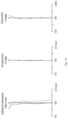
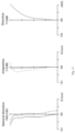
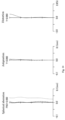
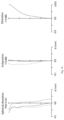
- each longitudinal aberration diagram shows spherical aberration (SA (mm)), astigmatism (AST (mm)) and distortion (DIS (%)) in turn from the left.
- the vertical axis represents the F number (represented by FNO in the diagram)
- the solid-line represents the characteristics of the d-line
- the short dashed-line represents the characteristics of F-line
- the long dashed-line represents the characteristics of C-line.
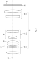
- Figs. 2 and 3 are lens configuration diagrams of an optical system according to Embodiment 1, with Fig. 2 showing an infinity focus state and Fig. 3 showing a closest focus state.
- the reference numerals indicating the configurations of the optical system are the same as the reference numerals of the corresponding configurations of the optical system 2 of the above embodiments.
- the positions of the first lens group 21 and the third lens group 23 on the optical axis C are fixed with respect to the photographing element (imaging plane) 3.
- Fig. 4 is a longitudinal aberration diagram in an infinity focus state
- Fig. 5 is a longitudinal aberration diagram at a magnification of "-0.5 times”
- Fig. 6 is a longitudinal aberration diagram at a magnification of"-1.0 times.
- Table 1 below shows the surface data of each lens
- Table 2 shows aspherical surface data
- Table 3 shows various data
- Table 4 shows lens group data
- Table 5 shows individual lens data.
- the focal length is 21.999, and the maximum image height is 4.000.
- Table 4 (Table 4) Lens group data Group Starting surface Focal length Lens configuration length Lens movement amount Magnification 1 1 8.242 5.725 0.000 - 2 9 -10.613 3.408 5.036 2.331 3 13 -35.740 3.103 0.000 1.145 Table 5 (Table 5) Individual lens data Lens Starting surface Focal length 1 1 12.458 2 3 -7.715 3 5 13.566 4 7 8.961 5 9 -6.197 6 11 19.077 7 13 -50.915 8 15 -121.484
- Figs. 7 and 8 are lens configuration diagrams of an optical system according to Embodiment 2, with Fig. 7 showing an infinity focus state and Fig. 8 showing a closest focus state.
- the reference numerals indicating the configurations of the optical system are the same as those of the corresponding configurations of the optical system 2 of the above embodiment.
- this optical system similarly, when focusing, the positions of the first lens group 21 and the third lens group 23 on the optical axis C are fixed with respect to the photographing element (imaging plane) 3.
- Figs. 12 and 13 are lens configuration diagrams of an optical system according to Embodiment 3, with Fig. 12 showing an infinity focus state and Fig. 13 showing a closest focus state.
- the reference numerals indicating the configurations of the optical system are the same as those of the corresponding configurations of the optical system 2 of the above embodiment.
- this optical system similarly, when focusing, the positions of the first lens group 21 and the third lens group 23 on the optical axis C are fixed with respect to the photographing element (imaging plane) 3.
- the focal length is 11.598, and the maximum image height is 2.060.
- Table 14 Lens group data Group Starting surface Focal length Lens configuration length Lens movement amount Magnification 1 1 4.076 3.159 0.000 - 2 7 -4.044 2.124 2.200 2.622 3 11 -38.871 1.429 0.000 1.085
- Table 15 Individual lens data Lens Starting surface Focal length 1 1 5.950 2 3 -5.141 3 5 3.323 4 7 -3.074 5 9 19.127 6 11 25.097 7 13 -15.804
- Figs. 17 and 18 are lens configuration diagrams of an optical system according to Embodiment 4, with Fig. 17 showing an infinity focus state and Fig. 18 showing a closest focus state.
- the reference numerals indicating the configurations of the optical system are the same as reference numerals of the corresponding configurations of the optical system 2 of the above embodiment.
- this optical system similarly, when focusing, the positions of the first lens group 21 and the third lens group 23 on the optical axis C are fixed with respect to the photographing element (imaging plane) 3.
- Fig. 19 is a longitudinal aberration diagram in an infinity focus state
- Fig. 20 is a longitudinal aberration diagram at a magnification of "-0.5 times”
- Fig. 21 is a longitudinal aberration diagram at a magnification of "-1.0 times”.
- Table 16 below shows the surface data of each lens
- Table 17 shows the aspheric surface data
- Table 18 shows various data
- Table 19 shows the lens group data
- Table 20 shows the individual lens data.
- the focal length is 21.999, and the maximum image height is 4.000.
- Table 19 Lens group data Group Starting surface Focal length Lens configuration length Lens movement amount Magnification 1 1 8.437 5.301 0.000 - 2 7 -11.495 3.350 5.396 2.269 3 11 -34.345 2.178 0.000 1.149 Table 20 (Table 20) Individual lens data Lens Starting surface Focal length 1 1 12.544 2 3 -8.154 3 5 5.982 4 7 -6.143 5 9 16.548 6 11 -39.691 7 13 -270.705
- conditional formula (1) is OAL2/OAL
- conditional formula (2) is OAL/f
- conditional formula (3) is
- conditional formula (4) is (1-b2 2 ) ⁇ b3 2
- conditional formula (5) is f2/f.
Landscapes
- Physics & Mathematics (AREA)
- General Physics & Mathematics (AREA)
- Optics & Photonics (AREA)
- Engineering & Computer Science (AREA)
- Multimedia (AREA)
- Signal Processing (AREA)
- Nonlinear Science (AREA)
- Lenses (AREA)
Abstract

Description
- The invention relates to an optical system having a plurality of lens groups and a photographing device having the optical system.
- Conventionally, optical systems having a first lens group having a positive refractive power, a second lens group having a negative refractive power and a third lens group sequentially arranged from an object side to an image side, with only the second lens group moving along the optical axis during focusing have been known as optical systems described in patent document 1 (
Japanese patent communique No.5749629 Japanese special publication communiqué No. 2021-173847 - However, the optical system described in
patent document 1 is not sufficient for close-range photographing, and the optical system described inpatent document 2 is not sufficiently miniaturized because a ratio of total lengths of the optical system and the focal length is large. - The prior art literature:
-
-
Patent document 1 isJapanese Patent communique No.5749629 -
Patent document 2 isJapanese special publication communiqué No. 2021-173847 - Therefore, the target of the present invention is to provide an optical system, which is miniaturized and capable of photographing at a close range, and a photographing device having the optical system.
- The optical system of the present invention includes:
- a first lens group having a positive refractive power, a second lens group having a negative refractive power and a third lens group having a negative refractive power, sequentially arranged from an object side to an image side;
- when focusing,
- the second lens group moves along an optical axis,
- positions of the first lens group and the third lens group relative to an imaging plane in a direction of the optical axis are fixed,
- when a distance from a face closest to the object side to a face closest to the image side of the second lens group is OAL2, and a distance from a face closest to the object side of the entire optical system to the imaging plane is OAL, it is satisfied that:

- It is also possible in the above optical system that
the second lens group includes: - at least one lens having a positive refractive power; and
- at least one lens having a negative refractive power,
- in the second lens group, a lens having the strongest positive refractive power is located closer to the image side than a lens having the strongest negative refractive power.
- In addition, it is also possible in the above optical system that
when a focal length of the entire optical system focusing at infinity is f, it is satisfied that:

- In addition, it is also possible in the above optical system that
when a maximum lateral magnification of the entire optical system is B, it is satisfied that:

- In addition, it is also possible in the above optical system that
when a lateral magnification of the second lens group focusing at infinity is b2 and a lateral magnification of the third lens group focusing at infinity is b3, it is satisfied that:

- In addition, it is also possible in the above optical system that
when a focal length of the entire optical system focusing at infinity is f, and a focal length of the second lens group is f2, it is satisfied that:

- In addition, the photographing device of the present invention includes:
- any of the above optical systems; and
- a photographing element arranged at a side of the imaging plane of the optical system and converting an optical image formed by the optical system into an electrical signal.
-
-
Fig. 1 is a schematic diagram showing a configuration of a photographing device according to an embodiment. -
Fig. 2 is a lens configuration diagram of an optical system according toembodiment 1 in an infinity focus state. -
Fig. 3 is a lens configuration diagram of an optical system according toembodiment 1 in a closest focus state. -
Fig. 4 is a longitudinal aberration diagram of an optical system according toembodiment 1 in an infinity focus state. -
Fig. 5 is a longitudinal aberration diagram of an optical system according toembodiment 1 at a magnification of "-0.5 times". -
Fig. 6 is a longitudinal aberration diagram of an optical system according toembodiment 1 at a magnification of "-1.0 times". -
Fig. 7 is a lens configuration diagram of an optical system according toembodiment 2 in an infinity focus state. -
Fig. 8 is a lens configuration diagram of an optical system according toembodiment 2 in a closest focus state. -
Fig. 9 is a longitudinal aberration diagram of an optical system according toembodiment 2 in an infinity focus state. -
Fig. 10 is a longitudinal aberration diagram of an optical system according toembodiment 2 at a magnification of "-0.5 times". -
Fig. 11 is a longitudinal aberration diagram of an optical system according toembodiment 2 at a magnification of "-1.0 times". -
Fig. 12 is a lens configuration diagram of an optical system according toembodiment 3 in an infinity focus state. -
Fig. 13 is a lens configuration diagram of an optical system according toembodiment 3 in a closest focus state. -
Fig. 14 is a longitudinal aberration diagram of an optical system according toembodiment 3 in an infinity focus state. -
Fig. 15 is a longitudinal aberration diagram of an optical system according toembodiment 3 at a magnification of "-0.5 times". -
Fig. 16 is a longitudinal aberration diagram of an optical system according toembodiment 3 at a magnification of "-1.0 times". -
Fig. 17 is a lens configuration diagram of an optical system according toembodiment 4 in an infinity focus state. -
Fig. 18 is a lens configuration diagram of an optical system according toembodiment 4 in a closest focus state. -
Fig. 19 is a longitudinal aberration diagram of an optical system according toembodiment 4 in an infinity focus state. -
Fig. 20 is a longitudinal aberration diagram of an optical system according toembodiment 4 at a magnification of "-0.5 times". -
Fig. 21 is a longitudinal aberration diagram of an optical system according toembodiment 4 at a magnification of "-1.0 times". - Hereinafter, an embodiment of the present invention will be described with reference to the drawings.
- As shown in
Fig. 1 , aphotographing device 1 according to the present embodiment includes anoptical system 2, a photographingelement 3 arranged at a position of an imaging plane of theoptical system 2, and aliquid crystal screen 4 for displaying the photographing (image) data transmitted from a photographingelement 3. In addition, the photographingdevice 1 includes a driving part (not shown in the figures) for driving theoptical system 2. The driving part is an actuator such as a VCM (Voice Coil Motor), to drive a predetermined lens or lens group and the like included in theoptical system 2 in a direction substantially perpendicular to a light receiving surface of the photographing element 3 (a direction of an optical axis). In addition, the photographingelement 3 is an element that converts an optical image formed by theoptical system 2 into an electrical signal (photographing data), and the photographingelement 3 of the present embodiment is a CMOS image sensor. - The
optical system 2 is a so-called internal focusing optical system, and theoptical system 2 of the present embodiment is a so-called periscope telephoto lens in which the optical axis (an optical path) C is bent by a reflective optical element such as a prism or a mirror. Specifically, theoptical system 2 includes aprism 20 that bends the optical axis C and a plurality of lens groups G arranged on the optical axis C sequentially from the object side to the image side along the optical axis C. In addition, theoptical system 2 includes anaperture diaphragm 24, anoptical filter 25 arranged between the plurality of lens groups G and the photographingelement 3, and alens barrel 26 holding the plurality of lens groups G. - The plurality of lens groups G at least include a
first lens group 21, asecond lens group 22, and athird lens group 23 sequentially from the object side to the image side along the optical axis C. Each of thelens groups - In addition, in the
optical system 2 of the present embodiment, thelens groups 21 to 23 are named for convenience, and include a lens group composed of only one optical element (lens, etc.). That is, the first tothird lens groups optical system 2, the optical elements (lenses, etc.) whose positions are fixed on the optical axis C during focusing are separated from the moving optical elements, and the at least one fixed optical element in a separated area is regarded as one lens group, and the at least one moving optical element in a separated area is regarded as another lens group. - In the above-mentioned
optical system 2, during focusing, thesecond lens group 22 moves along the optical axis C, and positions of thefirst lens group 21 and thethird lens group 23 in the direction of the optical axis C are fixed relative to the photographing element 3 (the imaging plane of the optical system 2). That is, in theoptical system 2 of the present embodiment, among thelens groups second lens group 22 constitutes a focusing lens group F. - Hereinafter, the
lens groups 21 to 23 in theoptical system 2 will be described in detail. - The
first lens group 21 includes a plurality of lenses (four lenses in an example of the present embodiment) having a positive refractive power. In addition, thesecond lens group 22 includes a plurality of lenses (two lenses in an example of the present embodiment) having a negative bending rate. In addition, thethird lens group 23 includes a plurality of lenses (two lenses in an example of the present embodiment) having a negative refractive power. - When a distance from a face closest to the object side to a face closest to the image side of the
second lens group 22 is OAL2 and a distance from a face closest to the object side of the entireoptical system 2 to the imaging plane is OAL, theoptical system 2 satisfies the following formula (1).
- In the above
optical system 2, among a plurality of lens groups G arranged along the optical axis C, thefirst lens group 21 having the positive refractive power is arranged closest to the object side, thesecond lens group 22 having the negative refractive power is arranged at the image side of thefirst lens group 21, and thethird lens group 23 having the negative refractive power is arranged closest to the image side. As a result, it is easy to obtain a focal power arrangement of telephoto in theoptical system 2, so that a focal length of thefirst lens group 21 may be shortened, resulting in that theoptical system 2 may be miniaturized (specifically, miniaturized in the direction of the optical axis C). - Moreover, by making the second lens group movable during focusing, the aberration variation balance with the front and
rear lens groups - Furthermore, by fixing the
first lens group 21 and thethird lens group 23 with respect to the imaging plane, only thesecond lens group 22 is set as a movable lens group, so that a load on a mechanism or actuator may be reduced, and therefore, the overall miniaturization of the photographingdevice 1 including theoptical system 2 may be realized. - In addition, the above formula (1) specifies a ratio (OAL2/OAL) of the distance from the face closest to the object side to the face closest to the image side of the
second lens group 22 to the distance from the face closest to the object side of the entireoptical system 2 to the imaging plane. When the ratio (OAL2/OAL) is lower than a lower limit value (0.06), the aberration correction in the entire focus area becomes insufficient and the imaging performance becomes insufficient. Therefore, in theoptical system 2 of the present embodiment, by setting the ratio (OAL2/OAL) of the distance from the face closest to the object side to the face closest to the image side of thesecond lens group 22 to the distance from the face closest to the object side of the entireoptical system 2 to the imaging plane within the range of formula (1), it is possible to perform sufficient aberration correction in the entire focused area, thereby ensuring sufficient imaging performance. - In addition, in the
optical system 2 of the present embodiment, the above ratio (OAL2/OAL) preferably satisfies the following formula.
- It is more preferable to satisfy the following formula.

- In addition, in the
optical system 2, thesecond lens group 22 has at least one lens having a positive refractive power and at least one lens having a negative refractive power. In thesecond lens group 22, alens 221 having the strongest positive refractive power may be arranged at a position closer to the image side than alens 222 having the strongest negative refractive power. - According to this configuration, aberration correction may be achieved in the entire focus area from infinity photographing to close range photographing just by moving the
second lens group 22. The details are as follows. - In order to realize the aberration correction in the entire focus area from infinity photographing to close range photographing just by moving the
second lens group 22, an on-axis light beam that is strongly converged by thefirst lens group 21 on the object side of thesecond lens group 22 is regarded as a properly converged light beam, and a negative focal power is needed to make a peripheral light beam jump up and be guided to the image side of thesecond lens group 22. In addition, on the image side of thesecond lens group 22, a positive focal power is required for convergence to obtain a desired F number. - Therefore, in the
optical system 2 of the present embodiment, as the configuration described above, thesecond lens group 22 has at least one lens having a positive refractive power and at least one lens having a negative refractive power. By adopting a configuration in which thelens 221 having the strongest positive refractive power is located at the position closer to the image side than thelens 222 having the strongest negative refractive power in thesecond lens group 22, a proper aberration correction may be achieved in the entire focus area from infinity photographing to close range photographing just by moving thesecond lens group 22. - In addition, in the
optical system 2, when a focal length of the entire optical system focusing at infinity is f, theoptical system 2 may satisfy the following formula (2).
- The above formula (2) specifies a ratio (OAL/f) of the distance from the face closest to the object side of the entire optical system to the imaging plane to the focal length, and when the ratio (OAL/f) exceeds an upper limit (2.00), it cannot be said that a total optical length is sufficiently shortened, and not only the
optical system 2, but also the entire photographingdevice 1 having theoptical system 2 cannot be miniaturized. Therefore, in theoptical system 2 of the present embodiment, by setting the ratio (OAL/f) of the distance from the face closest to the object side of the entire optical system to the imaging plane to the focal length within a range of formula (2), the total optical length may be sufficiently shortened, and thus, not only theoptical system 2 may be miniaturized, but also the entire photographingdevice 1 having theoptical system 2 may be miniaturized. - In addition, in the
optical system 2 of the present embodiment, the above ratio (OAL/f) preferably satisfies the following formula.
- It is more preferable to satisfy the following formula.

- In addition, in the
optical system 2, when a maximum lateral magnification of the entire optical system is B, theoptical system 2 may also satisfy the following formula (3).
- The above formula (3) specifies the maximum lateral magnification of the entire optical system, and when the value is lower than a lower limit (0.50), it cannot be said that close range photographing is fully realized, and a distance from the object that may be photographed cannot be shortened. Therefore, in the
optical system 2 of the present embodiment, by setting the maximum lateral magnification of the entire optical system within a range of formula (3), the distance from the object that may be photographed may be shortened, and thus, anoptical system 2 that is miniaturized and capable of photographing at a close range and a photographingdevice 1 having theoptical system 2 may be realized. - Here, the maximum lateral magnification is a numerical value indicating a degree of close range photographing, which is a ratio of a height of the image on a photographing surface to a height of the object of the subject. For example, when photographing at a close range and | B | is 1.00, sizes of the subject and the photographing surface are equal. In addition, when photographing at a long distance, | B | is close to 0.00.
- In addition, in the
optical system 2 of the present embodiment, the maximum lateral magnification of the entire optical system preferably satisfies the following formula.
- It is more preferable to satisfy the following formula.

- In addition, in the
optical system 2, when a lateral magnification of the second lens group focusing at infinity is b2 and a lateral magnification of the third lens group focusing at infinity is b3, theoptical system 2 may also satisfy the following formula (4).
- The above formula (4) specifies a ratio ((1-b22) × b32) of a movement amount of the imaging plane to a movement amount of the
second lens group 22 in the direction of the optical axis C. In the optical system with a whole extension mode, the numerical value corresponding to this formula is 1. However, in the internal focusing optical system of theoptical system 2 of the present embodiment, by increasing this ratio with a negative value, the close range photographing may be realized with a small movement amount, and the miniaturization of the entireoptical system 2 is realized. When the ratio ((1-b22) × b32) is less than a lower limit (-10.00), the movement amount of the imaging plane relative to the movement amount of thesecond lens group 22 in the direction of the optical axis C becomes too large to improve accuracy of the stop position of thesecond lens group 22 by a driving device such as an actuator. However, when the ratio ((1-b22) × b32) exceeds an upper limit (-2.00), the movement amount of thesecond lens group 22 for the close range photographing increases, so it is difficult to realize the miniaturization of the entireoptical system 2. Therefore, in theoptical system 2 of the present embodiment, by setting the ratio ((1-b22) × b32) of the movement amount of the imaging plane to the movement amount of thesecond lens group 22 in the direction of the optical axis C within a range of the above-mentioned formula (4), it is possible to achieve a balance between improving the accuracy of the stop position of thesecond lens group 22 by an actuator or the like during focusing and the miniaturization of the entireoptical system 2. - In addition, in the
optical system 2 of the present embodiment, the above ratio ((1-b22) × b32) preferably satisfies the following formula.
- It is more preferable to satisfy the following formula.

- In addition, in the
optical system 2, when a focal length of the entire optical system focusing at infinity is f and a focal length of the above-mentioned second lens group is f2, theoptical system 2 may also satisfy the following formula (5).
- The above formula (5) specifies a ratio (f2/f) of the focal length of the
second lens group 22 to the focal length of the entireoptical system 2 focusing at infinity. When this ratio (f2/f) is lower than a lower limit (-0.70), the optical power of thesecond lens group 22 becomes weak, and the movement amount of thesecond lens group 22 for the close range photographing becomes large, so it is difficult to realize the miniaturization of the entireoptical system 2. On the other hand, when the ratio (f2/f) exceeds an upper limit (-0.10), the movement amount of the imaging plane relative to the movement amount of thesecond lens group 22 in the direction of the optical axis C becomes too large to improve the accuracy of the stop position of thesecond lens group 22 by a driving device such as an actuator. Therefore, in theoptical system 2 of the present embodiment, by setting the ratio (f2/f) of the focal length of thesecond lens group 22 to the focal length of the entireoptical system 2 focusing at infinity within a range of the above-mentioned formula (5), it is possible to achieve a balance between the miniaturization of the entireoptical system 2 and improvement of the accuracy of the stop position of thesecond lens group 22 by an actuator or the like during focusing. - In addition, in the
optical system 2 of the present embodiment, the above ratio (f2/f) preferably satisfies the following formula.
- It is more preferable to satisfy the following formula.

- According to the
optical system 2 configured as above and the photographingdevice 1 having theoptical system 2, the miniaturation and close range photographing may be realized. That is, in theoptical system 2 of the present embodiment where thefirst lens group 21 has a positive refractive power, thesecond lens group 22 has a negative refractive power, and thethird lens group 23 has a negative refractive power, and thesecond lens group 22 is movable when focusing from infinity to close range, by appropriately selecting the configurations, magnifications, lens materials, etc. of thelens groups 21 to 23, an optical system, which has an overall small size and can fully realize the performance and chromatic aberration at the close range photographing, may be realized. - In addition, in the
optical system 2 and the photographingdevice 1 having theoptical system 2 according to the present embodiment, even in the so-called internal focusing optical system, the miniaturization and the like of theoptical system 2 and the photographingdevice 1 having theoptical system 2 may be realized. The details are as follows. - As a conventional focusing method of a lens, an optical system with a whole extension mode is known. The optical system with a whole extension mode adopts the way of extending the entire optical system to the object side when focusing from infinity to close range, and the entire optical system is fixed as one without being divided into subgroups, so it is relatively easy to improve the optical performance when designing. However, when the entire lens is focused, there is a difference between the positions where the lens system of peripheral image high beam passes between infinity and close range focus, and the variation of imaging plane bending becomes larger, and its aberration is difficult to correct. In addition, a movement distance of the entire lens during focusing increases in proportion to the square of the focal length. Therefore, especially for a telephoto lens with a long focal length, in order to achieve close range photographing, the movement amount of focusing becomes longer, and as a result, it is difficult to realize the miniaturization of the optical system and the photographing device.
- On the other hand, the internal focusing optical system, when focusing from infinity to close range, adopts a way of moving some lens groups in the optical system to the object side or the image side. Because the aberration correction corresponding to the object distances is distributed to respective groups, it is easier to correct the aberration in the focusing range. In addition, the sensitivity of the movement distance of the focus group during focusing may be improved, and the movement amount may be easily shortened.
- Therefore, in the photographing
device 1 of the present embodiment, even if the internal focusing optical system is adopted as theoptical system 2, it is possible to realize an optical system that has a small overall size and can fully realize the performance and chromatic aberration correction during close range photographing. -
Embodiments 1 to 4 of the optical system of the present invention will be described. In the following embodiments, the same reference numerals are used for the components corresponding to the components of theoptical system 2 of the above embodiments. In addition, in the tables of the following embodiments, r is the radius of curvature, d is the lens thickness or lens spacing, nd is a refractive index of a d-line, and vd represents an Abbe number based on the d-line. In addition, aspheric surface is defined by the following formula.
(Where, c is a curvature (1/r), h is a height from the optical axis, k is a conic coefficient, and A4, A6, A8 and A10 are aspheric coefficients of each order). - In addition, each longitudinal aberration diagram shows spherical aberration (SA (mm)), astigmatism (AST (mm)) and distortion (DIS (%)) in turn from the left. In the spherical aberration diagram, the vertical axis represents the F number (represented by FNO in the diagram), the solid-line represents the characteristics of the d-line, the short dashed-line represents the characteristics of F-line, and the long dashed-line represents the characteristics of C-line. In the astigmatism diagram, the vertical axis represents the maximum image height (represented by Y in the diagram), the solid-line represents the characteristics of the sagittal plane (represented by S in the diagram), and the dashed-line represents the characteristics of the meridian plane (represented by M in the diagram). In the distortion diagram, the vertical axis represents the maximum image height (represented by Y in the diagram).
-
Figs. 2 and3 are lens configuration diagrams of an optical system according toEmbodiment 1, withFig. 2 showing an infinity focus state andFig. 3 showing a closest focus state. In addition, the reference numerals indicating the configurations of the optical system are the same as the reference numerals of the corresponding configurations of theoptical system 2 of the above embodiments. In addition, in this optical system, when focusing, the positions of thefirst lens group 21 and thethird lens group 23 on the optical axis C are fixed with respect to the photographing element (imaging plane) 3. -
Fig. 4 is a longitudinal aberration diagram in an infinity focus state,Fig. 5 is a longitudinal aberration diagram at a magnification of "-0.5 times", andFig. 6 is a longitudinal aberration diagram at a magnification of"-1.0 times". In addition, Table 1 below shows the surface data of each lens, Table 2 shows aspherical surface data, Table 3 shows various data, Table 4 shows lens group data, and Table 5 shows individual lens data.Table 1 (Table 1) Surface data Surface number r d nd vd 1* 10.837 0.889 1.5731 37.65 2* -20.302 1.869 3* -11.842 0.400 1.6422 22.40 4* 8.631 0.400 5* 7.439 0.701 1.5445 55.96 6* -1016.183 0.459 7* -244.855 1.007 1.5445 55.96 8* -4.791 d8 (Aperture diaphragm) 9* -23.864 0.400 1.5445 55.96 10* 3.953 2.049 11* 7.996 0.959 1.6714 19.27 12* 20.258 d12 13* -26.885 0.600 1.6714 19.27 14* -127.054 1.443 15* -14.148 1.060 1.5731 37.65 16* -18.241 1.822 17 ∞ 0.210 1.5168 64.20 18 ∞ 0.390 * for aspheric surface Table 2 (Table 2) Aspheric surface data (the aspheric coefficient not shown is 0.00.) Surface number k A4 A6 A8 A10 1 0.0000E+00 -1.1639E-05 6.0054E-05 8.6396E-06 -2.2041E-07 2 0.0000E+00 5.8633E-04 7.3252E-05 7.4744E-06 -5.8661E-07 3 0.0000E+00 -7.0037E-04 -1.9898E-04 -1.8774E-05 2.9685E-07 4 0.0000E+00 -1.1742E-03 -1.9647E-04 -2.4243E-05 5.3635E-06 5 0.0000E+00 -1.2977E-03 -9.0202E-05 -2.2704E-06 9.5701E-07 6 0.0000E+00 1.0370E-03 1.7134E-05 2.3536E-06 -1.7400E-06 7 0.0000E+00 -5.1023E-04 -4.7470E-06 -9.8158E-06 3.7361E-07 8 0.0000E+00 -2.8113E-04 -5.1933E-05 -6.3363E-06 3.6540E-07 9 0.0000E+00 8.8416E-03 -1.4970E-03 1.9667E-04 -1.3207E-05 10 0.0000E+00 7.6657E-03 -7.8779E-04 1.2420E-04 -4.5422E-06 11 0.0000E+00 -6.0882E-03 3.6197E-04 -4.1107E-05 2.7115E-06 12 0.0000E+00 -6.6253E-03 2.4105E-04 -3.3557E-05 1.3859E-06 13 0.0000E+00 2.0583E-04 2.7586E-04 -2.5465E-05 -2.7532E-07 14 0.0000E+00 1.4314E-03 3.1864E-04 -8.5224E-06 -1.1200E-06 15 0.0000E+00 -4.2498E-04 1.1331E-04 1.8972E-05 -8.9160E-07 16 0.0000E+00 -1.8677E-03 9.7671E-05 -1.7520E-07 2.0773E-07 Table 3 (Table 3) Various data object distance ∞ 44.617 21.900 lateral magnification - -0.5 times -1.0 times F number 4.100 4.604 4.983 lens total length 21.680 21.680 21.680 d8 1.000 3.112 6.036 d12 6.022 3.910 0.986 - The focal length is 21.999, and the maximum image height is 4.000.
Table 4 (Table 4) Lens group data Group Starting surface Focal length Lens configuration length Lens movement amount Magnification 1 1 8.242 5.725 0.000 - 2 9 -10.613 3.408 5.036 2.331 3 13 -35.740 3.103 0.000 1.145 Table 5 (Table 5) Individual lens data Lens Starting surface Focal length 1 1 12.458 2 3 -7.715 3 5 13.566 4 7 8.961 5 9 -6.197 6 11 19.077 7 13 -50.915 8 15 -121.484 -
Figs. 7 and8 are lens configuration diagrams of an optical system according toEmbodiment 2, withFig. 7 showing an infinity focus state andFig. 8 showing a closest focus state. In addition, the reference numerals indicating the configurations of the optical system are the same as those of the corresponding configurations of theoptical system 2 of the above embodiment. In addition, in this optical system, similarly, when focusing, the positions of thefirst lens group 21 and thethird lens group 23 on the optical axis C are fixed with respect to the photographing element (imaging plane) 3. -
Fig. 9 is a longitudinal aberration diagram in an infinity focus state,Fig. 10 is a longitudinal aberration diagram at a magnification of "-0.5 times", andFig. 11 is a longitudinal aberration diagram at a magnification of"-1.0 times". In addition, Table 6 below shows the surface data of each lens, Table 7 shows aspheric surface data, Table 8 shows various data, Table 9 shows lens group data, and Table 10 shows individual lens data.Table 6 (Table 6) Surface data Surface number r d nd vd 1* 5.000 0.693 1.5731 37.65 2* -10.734 0.966 3* -8.150 0.300 1.6714 19.27 4* 5.654 0.300 5* 4.317 0.907 1.5445 55.96 6* -2.867 d6 (Aperture diaphragm) 7* -5.422 0.300 1.5445 55.96 8* 2.824 0.685 9* 27.713 0.405 1.6714 19.27 10* -8.501 0.300 11* -10.352 0.300 1.5445 55.96 12* 24.347 d12 13* -13.515 0.600 1.5445 55.96 14* -25.363 0.368 15* -6.612 0.407 1.6714 19.27 16* -6.720 0.500 17 ∞ 0.105 1.5168 64.20 18 ∞ 0.195 * for aspheric surface Table 7 (Table 7) Aspheric surface data (the aspheric coefficient not shown is 0.00.) Surface number k A4 A6 A8 A10 1 0.0000E+00 -2.3666E-03 2.0426E-05 6.8914E-04 -6.1516E-05 2 0.0000E+00 1.6713E-03 8.7447E-04 7.9219E-04 -1.5080E-04 3 0.0000E+00 -1.9033E-03 -1.1546E-03 -4.6620E-04 -4.3690E-04 4 0.0000E+00 -3.2511E-03 -3.0497E-03 -6.7443E-04 1.5675E-04 5 0.0000E+00 -1.1837E-02 -2.7722E-03 -7.9426E-04 4.8106E-04 6 0.0000E+00 4.1623E-04 -4.6327E-04 -1.2627E-03 3.9072E-04 7 0.0000E+00 1.4546E-01 -1.0408E-01 4.7577E-02 -9.9469E-03 8 0.0000E+00 1.6352E-01 -6.6907E-02 2.2009E-02 -1.6217E-04 9 0.0000E+00 9.3001E-03 3.1386E-02 -3.5351E-03 -2.5583E-03 10 0.0000E+00 4.5596E-03 1.5161E-02 2.1792E-02 -1.1358E-02 11 0.0000E+00 -1.2992E-01 2.1 642E-02 2.9409E-02 -2.0420E-02 12 0.0000E+00 -1.3818E-01 3.8975E-02 -5.9382E-03 -4.1109E-03 13 0.0000E+00 -2.9073E-02 -8.7698E-03 2.5602E-04 -1.9794E-05 14 0.0000E+00 -2.6118E-02 -6.2895E-03 9.2413E-04 -6.0528E-05 15 0.0000E+00 -1.7191E-02 9.6305E-03 -3.2638E-04 -1.8985E-04 16 0.0000E+00 -1.7921E-02 6.5500E-03 1.1147E-03 -3.4194E-04 Table 8 (Table 8) Various data object distance ∞ 23.135 10.954 lateral magnification - -0.5 times -1.0 times F number 3.400 3.744 3.931 lens total length 10.800 10.800 10.800 d6 0.500 1.492 2.978 d12 2.968 1.976 0.490 - The focal length is 11.600 and the maximum image height is 2.060.
Table 9 (Table 9) Lens group data Group Starting surface Focal length Lens configuration length Lens movement amount Magnification 1 1 4.167 3.167 0.000 - 2 7 -3.745 1.990 2.478 2.613 3 13 -58.120 1.376 0.000 1.065 Table 10 (Table 10) Individual lens data Lens Starting surface Focal length 1 1 6.049 2 3 -4.929 3 5 3.311 4 7 -3.367 5 9 9.733 6 11 -13.299 7 13 -54.100 8 15 1192.fi95 -
Figs. 12 and13 are lens configuration diagrams of an optical system according toEmbodiment 3, withFig. 12 showing an infinity focus state andFig. 13 showing a closest focus state. In addition, the reference numerals indicating the configurations of the optical system are the same as those of the corresponding configurations of theoptical system 2 of the above embodiment. In addition, in this optical system, similarly, when focusing, the positions of thefirst lens group 21 and thethird lens group 23 on the optical axis C are fixed with respect to the photographing element (imaging plane) 3. -
Fig. 14 is a longitudinal aberration diagram in an infinity focus state,Fig. 15 is a longitudinal aberration diagram at a magnification of "-0.5 times", andFig. 16 is a longitudinal aberration diagram at a magnification of "-1.0 times". In addition, Table 11 below shows the surface data of each lens, Table 12 shows the aspheric surface data, Table 13 shows various data, Table 14 shows the lens group data, and Table 15 shows the individual lens data.Table 11 (Table 11) Surface data Surface number r d nd vd 1* 5.000 0.706 1.5731 37.65 2* -10.173 0.993 3* -8.056 0.300 1.6714 19.27 4* 6.129 0.300 5* 4.306 0.860 1.5445 55.96 6* -2.901 d6 (Aperture diaphragm) 7* -4.269 0.388 1.5445 55.96 8* 2.842 1.255 9* 33.107 0.481 1.6714 19.27 10* -20.856 d10 11* -8.636 0.600 1.6714 19.27 12* -5.869 0.397 13* -2.388 0.432 1.5445 55.96 14* -3.516 0.500 15 ∞ 0.105 1.5168 64.20 16 ∞ 0.195 * for aspheric surface Table 12 (Table 12) Aspheric surface data (the aspheric coefficient not shown is 0.00.) Surface number k A4 A6 A8 A10 1 0.0000E+00 -1.9112E-03 -1.5546E-05 6.7772E-04 -6.1390E-05 2 0.0000E+00 1.8475E-03 7.8046E-04 7.4538E-04 -1.4350E-04 3 0.0000E+00 -2.4046E-03 -1.4414E-03 -5.4986E-04 -4.4954E-04 4 0.0000E+00 -3.2006E-03 -3.1773E-03 -7.5860E-04 1.7843E-04 5 0.0000E+00 -1.2499E-02 -2.9279E-03 -8.2432E-04 5.1155E-04 6 0.0000E+00 -2.6964E-04 -7.1603E-04 -1.2165E-03 3.9514E-04 7 0.0000E+00 1.4553E-01 -1.0374E-01 5.0677E-02 -1.1549E-02 8 0.0000E+00 1.6999E-01 -7.8555E-02 3.6428E-02 -3.2533E-03 9 0.0000E+00 -3.2310E-02 7.0395E-03 -3.1606E-03 9.0266E-04 10 0.0000E+00 -4.4445E-02 4.4951E-03 -2.4390E-03 1.8147E-04 11 0.0000E+00 -2.7469E-02 -6.6085E-03 2.3747E-04 3.3901E-04 12 0.0000E+00 -2.1601E-02 -6.6923E-04 5.7099E-04 -1.0567E-05 13 0.0000E+00 3.5570E-02 6.5430E-03 -7.4509E-04 -6.9896E-05 14 0.0000E+00 2.5797E-02 -3.5508E-03 2.0065E-03 -3.3999E-04 Table 13 (Table 13) Various data object distance ∞ 23.360 11.411 lateral magnification - -0.5 times -1.0 times F number 3.400 3.797 4.101 lens total length 10.800 10.800 10.800 d6 0.500 1.433 2.700 d10 2.787 1.854 0.587 - The focal length is 11.598, and the maximum image height is 2.060.
Table 14 (Table 14) Lens group data Group Starting surface Focal length Lens configuration length Lens movement amount Magnification 1 1 4.076 3.159 0.000 - 2 7 -4.044 2.124 2.200 2.622 3 11 -38.871 1.429 0.000 1.085 Table 15 (Table 15) Individual lens data Lens Starting surface Focal length 1 1 5.950 2 3 -5.141 3 5 3.323 4 7 -3.074 5 9 19.127 6 11 25.097 7 13 -15.804 -
Figs. 17 and18 are lens configuration diagrams of an optical system according toEmbodiment 4, withFig. 17 showing an infinity focus state andFig. 18 showing a closest focus state. In addition, the reference numerals indicating the configurations of the optical system are the same as reference numerals of the corresponding configurations of theoptical system 2 of the above embodiment. In addition, in this optical system, similarly, when focusing, the positions of thefirst lens group 21 and thethird lens group 23 on the optical axis C are fixed with respect to the photographing element (imaging plane) 3. -
Fig. 19 is a longitudinal aberration diagram in an infinity focus state,Fig. 20 is a longitudinal aberration diagram at a magnification of "-0.5 times", andFig. 21 is a longitudinal aberration diagram at a magnification of "-1.0 times". In addition, Table 16 below shows the surface data of each lens, Table 17 shows the aspheric surface data, Table 18 shows various data, Table 19 shows the lens group data, and Table 20 shows the individual lens data.Table 16 (Table 16) Surface data Surface number r d nd vd 1* 11.363 0.891 1.5445 55.96 2* -16.648 2.105 3* -11.791 0.483 1.6161 25.78 4* 8.889 0.508 5* 9.425 1.316 1.5445 55.96 6* -4.732 d6 (Aperture diaphragm) 7* -18.298 0.400 1.5445 55.96 8* 4.125 1.654 9* 9.133 1.296 1.6560 21.25 10* 54.302 d10 11* -24.402 0.600 1.6714 19.27 12* -292.433 0.788 13* -39.540 0.790 1.5880 28.42 14* -52.998 2.870 15 ∞ 0.210 1.5168 64.20 16 ∞ 0.390 * for aspheric surface Table 17 (Table 17) Aspheric surface data (the aspheric coefficient not shown is 0.00.) Surface number k A4 A6 A8 A10 1 0.0000E+00 -2.4234E-04 6.7694E-05 9.5189E-06 -3.2738E-07 2 0.0000E+00 7.4726E-04 8.5317E-05 7.9662E-06 -6.4674E-07 3 0.0000E+00 -1.0455E-03 -2.7135E-04 -2.4506E-05 -1.2958E-06 4 0.0000E+00 -1.4090E-03 -2.6033E-04 -3.6940E-05 4.6898E-06 5 0.0000E+00 -1.9939E-03 -1.4629E-04 -1.7838E-05 2.630 1E-06 6 0.0000E+00 -2.8018E-04 -9.8170E-05 -5.4890E-06 3.8947E-07 7 0.0000E+00 9.8294E-03 -1.4827E-03 1.6449E-04 -9.6737E-06 8 0.0000E+00 7.9215E-03 -4.7219E-04 4.8074E-05 2.5181E-06 9 0.0000E+00 -6.0098E-03 4.9475E-04 -5.6628E-05 4.1063E-06 10 0.0000E+00 -6.0192E-03 2.436 1E-04 -3.5619E-05 1.5327E-06 11 0.0000E+00 1.7119E-03 1.3443E-04 -3.2076E-05 5.3290E-07 12 0.0006E+00 4.0167E-03 1.8733E-04 -5.3277E-06 -1.3317E-06 13 0.0000E+00 -8.6012E-04 2.3103E-04 1.6139E-05 -1.2058E-06 14 0.0000E+00 -3.3438E-03 2.4644E-04 -1.5055E-05 7.3173E-07 Table 18 (Table 18) Various data object distance ∞ 45.139 22.397 lateral magnification -0.5 times -1.0 times F number 4.100 4.608 4.987 lens total length 21.680 21.680 21.680 d6 1.000 3.249 6.396 d10 6.380 4.131 0.984 -
Table 19 (Table 19) Lens group data Group Starting surface Focal length Lens configuration length Lens movement amount Magnification 1 1 8.437 5.301 0.000 - 2 7 -11.495 3.350 5.396 2.269 3 11 -34.345 2.178 0.000 1.149 Table 20 (Table 20) Individual lens data Lens Starting surface Focal length 1 1 12.544 2 3 -8.154 3 5 5.982 4 7 -6.143 5 9 16.548 6 11 -39.691 7 13 -270.705 - In the
above embodiments 1 to 4, the values corresponding to the conditions of the above embodiments are shown in the following Table 21. In addition, in Table 21, conditional formula (1) is OAL2/OAL, conditional formula (2) is OAL/f, conditional formula (3) is | B |, conditional formula (4) is (1-b22)×b32, and conditional formula (5) is f2/f.Table 21 (Table 21) Corresponding values of conditional formulas Embodiment 1 Embodiment 2Embodiment 3Embodiment 4Conditional formula (1) 0.157 0.184 0.197 0.155 Conditional formula (2) 0.986 0.931 0.931 0.985 Conditional formula (3) 1.000 1.000 1.000 1.000 Conditional formula (4) -5.813 -6.610 -6.916 -5.477 Conditional formula (5) -0.482 -0.323 -0.349 -0.523 OAL2 3.408 1.990 2.124 3.350 OAL 21.680 10.800 10.800 21.680 f 21.999 11.600 11.598 21.999 | B | 1.000 1.000 1.000 1.000 b2 2.331 2.613 2.622 2.269 b3 1.145 1.065 1.085 1.149 f2 -10.613 -3.745 -4.044 -11.495 - In order to indicate the present invention, while referring to the attached drawings, the present invention has been properly and fully explained through the embodiments, but those skilled in the art should realize that the above embodiments may be easily changed and/or improved. Therefore, as long as the alteration or improvement carried out by a person skilled in the art does not deviate from the scope of the claims recorded in the claims, the alteration or improvement shall be interpreted as being included in the scope of the rights of the claims.
- Description of reference numerals:
1... photographing device, 2... optical system, 20... prism (reflective optical element), 21... first lens group, 22... second lens group, 221... lens having the strongest positive refractive power insecond lens group second lens group
Claims (7)
- An optical system, comprisinga first lens group having a positive refractive power, a second lens group having a negative refractive power and a third lens group having a negative refractive power, sequentially arranged from an object side to an image side,wherein when focusing,the second lens group moves along an optical axis,positions of the first lens group and the third lens group relative to an imaging plane in a direction of the optical axis are fixed,when a distance from a face closest to the object side to a face closest to the image side of the second lens group is OAL2, and a distance from a face closest to the object side of the entire optical system to the imaging plane is OAL, it is satisfied that:

- The optical system according to claim 1, wherein,
the second lens group comprises:at least one lens having a positive refractive power; andat least one lens having a negative refractive power,in the second lens group, a lens having the strongest positive refractive power is located closer to the image side than a lens having the strongest negative refractive power. - The optical system according to claim 1 or 2, wherein,
when a focal length of the entire optical system focusing at infinity is f, it is satisfied that:
- The optical system according to any one of claims 1-3, wherein,
when a maximum lateral magnification of the entire optical system is B, it is satisfied that:
- The optical system according to any one of claims 1-4, wherein,
when a lateral magnification of the second lens group focusing at infinity is b2 and a lateral magnification of the third lens group focusing at infinity is b3, it is satisfied that:
- The optical system according to any one of claims 1-5, wherein,
when a focal length of the entire optical system focusing at infinity is f, and a focal length of the second lens group is set to f2, it is satisfied that:
- A photographing device, comprising:an optical system according to any one of claims 1 to 6; anda photographing element arranged at a side of the imaging plane of the optical system and converting an optical image formed by the optical system into an electrical signal.
Applications Claiming Priority (1)
| Application Number | Priority Date | Filing Date | Title |
|---|---|---|---|
| PCT/CN2022/091050 WO2023212878A1 (en) | 2022-05-05 | 2022-05-05 | Optical device and photographing device comprising same |
Publications (2)
| Publication Number | Publication Date |
|---|---|
| EP4521155A1 true EP4521155A1 (en) | 2025-03-12 |
| EP4521155A4 EP4521155A4 (en) | 2025-07-23 |
Family
ID=88646106
Family Applications (1)
| Application Number | Title | Priority Date | Filing Date |
|---|---|---|---|
| EP22940574.1A Pending EP4521155A4 (en) | 2022-05-05 | 2022-05-05 | OPTICAL DEVICE AND PHOTOGRAPHIC DEVICE THEREOF |
Country Status (6)
| Country | Link |
|---|---|
| US (1) | US12596240B2 (en) |
| EP (1) | EP4521155A4 (en) |
| JP (1) | JP7579859B2 (en) |
| KR (1) | KR102936816B1 (en) |
| CN (1) | CN117355782B (en) |
| WO (1) | WO2023212878A1 (en) |
Families Citing this family (1)
| Publication number | Priority date | Publication date | Assignee | Title |
|---|---|---|---|---|
| CN117355781A (en) * | 2022-05-05 | 2024-01-05 | 北京小米移动软件有限公司 | Optical systems, and photographing devices equipped with optical systems |
Family Cites Families (24)
| Publication number | Priority date | Publication date | Assignee | Title |
|---|---|---|---|---|
| TW338798B (en) * | 1996-09-12 | 1998-08-21 | Nicon Kk | Variable-fold optic system |
| JP5101878B2 (en) * | 2006-12-28 | 2012-12-19 | 富士フイルム株式会社 | telescope lens |
| WO2011118554A1 (en) * | 2010-03-26 | 2011-09-29 | コニカミノルタオプト株式会社 | Imaging lens, imaging optical device, and digital equipment |
| CN102236152B (en) | 2010-04-29 | 2013-01-23 | 大立光电股份有限公司 | Image pickup lens group |
| US9625689B2 (en) * | 2010-09-17 | 2017-04-18 | Nikon Corporation | Optical system, optical apparatus equipped therewith, and method for manufacturing optical system |
| JP5749629B2 (en) | 2011-11-01 | 2015-07-15 | 株式会社タムロン | Inner focus telephoto lens |
| JP5818209B2 (en) | 2011-12-21 | 2015-11-18 | 株式会社タムロン | Macro lens |
| JP5963565B2 (en) * | 2012-06-21 | 2016-08-03 | キヤノン株式会社 | Zoom lens and imaging apparatus having the same |
| JP6393029B2 (en) * | 2013-10-07 | 2018-09-19 | 株式会社タムロン | Photographing lens and photographing apparatus |
| JP6325284B2 (en) * | 2014-02-28 | 2018-05-16 | 株式会社タムロン | Inner focus lens |
| JP2015163928A (en) | 2014-02-28 | 2015-09-10 | 株式会社タムロン | Inner focus lens |
| CN106255912B (en) * | 2014-11-26 | 2019-07-05 | 奥林巴斯株式会社 | Objective lens optical system |
| JP6526992B2 (en) | 2015-03-24 | 2019-06-05 | 株式会社タムロン | Photographing lens and photographing device |
| JP6562692B2 (en) * | 2015-04-24 | 2019-08-21 | キヤノン株式会社 | Optical system and imaging apparatus having the same |
| JP6388851B2 (en) * | 2015-06-08 | 2018-09-12 | 富士フイルム株式会社 | Imaging lens and imaging apparatus |
| JP6266189B1 (en) * | 2016-05-16 | 2018-01-24 | オリンパス株式会社 | Objective optical system |
| KR102436510B1 (en) | 2017-06-30 | 2022-08-25 | 삼성전자주식회사 | Optical lens assembly and electronic device comprising the same |
| JP7154851B2 (en) * | 2018-07-13 | 2022-10-18 | キヤノン株式会社 | Zoom lens and imaging device |
| JP7166980B2 (en) * | 2019-04-12 | 2022-11-08 | キヤノン株式会社 | Optical system and imaging device having the same |
| JP7241674B2 (en) * | 2019-06-27 | 2023-03-17 | 富士フイルム株式会社 | Imaging lens and imaging device |
| CN112612127B (en) * | 2019-09-18 | 2022-05-24 | Oppo广东移动通信有限公司 | Zoom lens, imaging module and electronic equipment |
| JP7376421B2 (en) * | 2020-04-23 | 2023-11-08 | 富士フイルム株式会社 | Imaging lens and imaging device |
| CN112882213B (en) | 2021-01-20 | 2023-02-17 | 维沃移动通信有限公司 | Optical lens, camera module and electronic equipment |
| JP2023149130A (en) * | 2022-03-30 | 2023-10-13 | キヤノン株式会社 | Optical system and imaging device having the same |
-
2022
- 2022-05-05 JP JP2022534448A patent/JP7579859B2/en active Active
- 2022-05-05 US US18/289,634 patent/US12596240B2/en active Active
- 2022-05-05 WO PCT/CN2022/091050 patent/WO2023212878A1/en not_active Ceased
- 2022-05-05 KR KR1020237038274A patent/KR102936816B1/en active Active
- 2022-05-05 EP EP22940574.1A patent/EP4521155A4/en active Pending
- 2022-05-05 CN CN202280001656.8A patent/CN117355782B/en active Active
Also Published As
| Publication number | Publication date |
|---|---|
| JP7579859B2 (en) | 2024-11-08 |
| CN117355782B (en) | 2026-01-09 |
| WO2023212878A1 (en) | 2023-11-09 |
| EP4521155A4 (en) | 2025-07-23 |
| US12596240B2 (en) | 2026-04-07 |
| CN117355782A (en) | 2024-01-05 |
| US20250076619A1 (en) | 2025-03-06 |
| KR102936816B1 (en) | 2026-03-10 |
| JP2024519623A (en) | 2024-05-21 |
| KR20230162717A (en) | 2023-11-28 |
Similar Documents
| Publication | Publication Date | Title |
|---|---|---|
| EP2071379B1 (en) | Macro lens of the telephoto type having three lens groups and front focusing, method for its manufacture | |
| US6671103B2 (en) | Zoom lens and optical apparatus using the same | |
| US8107174B2 (en) | Wide-angle lens, imaging apparatus, and method for manufacturing wide-angle lens | |
| US8300318B2 (en) | Zoom lens system, imaging device and camera | |
| US7852567B1 (en) | Zoom lens system | |
| US20100110561A1 (en) | Rear focus wide-angle lens system and electronic imaging device using the same | |
| CN111830692B (en) | Photographic lens and photographic device | |
| US6560042B2 (en) | Wide-angle lens system and a focusing method thereof | |
| EP4521155A1 (en) | Optical device and photographing device comprising same | |
| JP2000035533A (en) | Imaging lens | |
| JPH09258098A (en) | Photographing lens | |
| JP3392881B2 (en) | Zoom lens | |
| JP4027343B2 (en) | Zoom lens and imaging apparatus using the same | |
| CN115104055A (en) | Optical system, optical apparatus, and method of manufacturing optical system | |
| CN116583773B (en) | Optical system, and camera device equipped with optical system | |
| JP2001133684A (en) | Shooting lens | |
| EP4521152A1 (en) | Optical system and imaging device having optical system | |
| JP2006133283A (en) | Small zoom lens | |
| JP4203330B2 (en) | Zoom lens and camera device | |
| CN115685494A (en) | Optical system and image pickup apparatus | |
| JP2019168724A (en) | Wide angle lens and imaging apparatus | |
| US20080106802A1 (en) | Zoom lens system and optical apparatus using the same | |
| JPH06265781A (en) | Wide angle photographic lens | |
| JPH06265780A (en) | Wide angle photographic lens | |
| EP2287652A1 (en) | Optical imaging system, camera device, and hand-held data terminal device |
Legal Events
| Date | Code | Title | Description |
|---|---|---|---|
| STAA | Information on the status of an ep patent application or granted ep patent |
Free format text: STATUS: THE INTERNATIONAL PUBLICATION HAS BEEN MADE |
|
| PUAI | Public reference made under article 153(3) epc to a published international application that has entered the european phase |
Free format text: ORIGINAL CODE: 0009012 |
|
| STAA | Information on the status of an ep patent application or granted ep patent |
Free format text: STATUS: REQUEST FOR EXAMINATION WAS MADE |
|
| 17P | Request for examination filed |
Effective date: 20231123 |
|
| AK | Designated contracting states |
Kind code of ref document: A1 Designated state(s): AL AT BE BG CH CY CZ DE DK EE ES FI FR GB GR HR HU IE IS IT LI LT LU LV MC MK MT NL NO PL PT RO RS SE SI SK SM TR |
|
| A4 | Supplementary search report drawn up and despatched |
Effective date: 20250624 |
|
| RIC1 | Information provided on ipc code assigned before grant |
Ipc: G02B 15/14 20060101AFI20250617BHEP Ipc: G02B 15/00 20060101ALI20250617BHEP Ipc: G02B 15/17 20060101ALI20250617BHEP Ipc: G02B 9/12 20060101ALI20250617BHEP Ipc: G02B 13/00 20060101ALI20250617BHEP Ipc: G02B 9/64 20060101ALI20250617BHEP Ipc: G02B 13/02 20060101ALI20250617BHEP |
|
| DAV | Request for validation of the european patent (deleted) | ||
| DAX | Request for extension of the european patent (deleted) |