EP4521097A1 - Integrierte optofluidische abfragemodule, durchflusszytometer damit und verfahren zur verwendung davon - Google Patents
Integrierte optofluidische abfragemodule, durchflusszytometer damit und verfahren zur verwendung davon Download PDFInfo
- Publication number
- EP4521097A1 EP4521097A1 EP24198380.8A EP24198380A EP4521097A1 EP 4521097 A1 EP4521097 A1 EP 4521097A1 EP 24198380 A EP24198380 A EP 24198380A EP 4521097 A1 EP4521097 A1 EP 4521097A1
- Authority
- EP
- European Patent Office
- Prior art keywords
- light
- flow cell
- flow
- integrated
- optofluidic
- Prior art date
- Legal status (The legal status is an assumption and is not a legal conclusion. Google has not performed a legal analysis and makes no representation as to the accuracy of the status listed.)
- Pending
Links
Images

Classifications
-
- G—PHYSICS
- G01—MEASURING; TESTING
- G01N—INVESTIGATING OR ANALYSING MATERIALS BY DETERMINING THEIR CHEMICAL OR PHYSICAL PROPERTIES
- G01N15/00—Investigating characteristics of particles; Investigating permeability, pore-volume or surface-area of porous materials
- G01N15/10—Investigating individual particles
- G01N15/14—Optical investigation techniques, e.g. flow cytometry
- G01N15/1434—Optical arrangements
- G01N15/1436—Optical arrangements the optical arrangement forming an integrated apparatus with the sample container, e.g. a flow cell
-
- G—PHYSICS
- G01—MEASURING; TESTING
- G01N—INVESTIGATING OR ANALYSING MATERIALS BY DETERMINING THEIR CHEMICAL OR PHYSICAL PROPERTIES
- G01N15/00—Investigating characteristics of particles; Investigating permeability, pore-volume or surface-area of porous materials
- G01N15/10—Investigating individual particles
- G01N15/14—Optical investigation techniques, e.g. flow cytometry
- G01N15/1456—Optical investigation techniques, e.g. flow cytometry without spatial resolution of the texture or inner structure of the particle, e.g. processing of pulse signals
- G01N15/1459—Optical investigation techniques, e.g. flow cytometry without spatial resolution of the texture or inner structure of the particle, e.g. processing of pulse signals the analysis being performed on a sample stream
-
- G—PHYSICS
- G01—MEASURING; TESTING
- G01N—INVESTIGATING OR ANALYSING MATERIALS BY DETERMINING THEIR CHEMICAL OR PHYSICAL PROPERTIES
- G01N15/00—Investigating characteristics of particles; Investigating permeability, pore-volume or surface-area of porous materials
- G01N15/10—Investigating individual particles
- G01N15/14—Optical investigation techniques, e.g. flow cytometry
- G01N15/1434—Optical arrangements
- G01N2015/1438—Using two lasers in succession
-
- G—PHYSICS
- G01—MEASURING; TESTING
- G01N—INVESTIGATING OR ANALYSING MATERIALS BY DETERMINING THEIR CHEMICAL OR PHYSICAL PROPERTIES
- G01N15/00—Investigating characteristics of particles; Investigating permeability, pore-volume or surface-area of porous materials
- G01N15/10—Investigating individual particles
- G01N15/14—Optical investigation techniques, e.g. flow cytometry
- G01N15/1434—Optical arrangements
- G01N2015/144—Imaging characterised by its optical setup
-
- G—PHYSICS
- G01—MEASURING; TESTING
- G01N—INVESTIGATING OR ANALYSING MATERIALS BY DETERMINING THEIR CHEMICAL OR PHYSICAL PROPERTIES
- G01N15/00—Investigating characteristics of particles; Investigating permeability, pore-volume or surface-area of porous materials
- G01N15/10—Investigating individual particles
- G01N15/14—Optical investigation techniques, e.g. flow cytometry
- G01N15/1434—Optical arrangements
- G01N2015/1452—Adjustment of focus; Alignment
-
- G—PHYSICS
- G01—MEASURING; TESTING
- G01N—INVESTIGATING OR ANALYSING MATERIALS BY DETERMINING THEIR CHEMICAL OR PHYSICAL PROPERTIES
- G01N2201/00—Features of devices classified in G01N21/00
- G01N2201/08—Optical fibres; light guides
- G01N2201/0826—Fibre array at source, distributing
Definitions
- Flow cytometry is a technique used to characterize and, in some instances, sort biological material, such as cells of a blood sample or particles of interest in another type of biological or chemical sample.
- a flow cytometer typically includes a sample reservoir for receiving a fluid sample, such as a blood sample, and a sheath reservoir containing a sheath fluid.
- the flow cytometer transports the particles (including cells) in the fluid sample as a cell stream to a flow cell, while also directing the sheath fluid to the flow cell.
- the flow stream is irradiated with light from a light source. Variations in the materials in the flow stream, such as morphologies or the presence of fluorescent labels, may cause variations in the observed light and these variations allow for characterization and separation.
- flow cells In conventional flow cytometers, flow cells must be properly aligned with the light source and light collection elements such that light irradiates the flow cell in an intended manner. Assembly of flow cytometers is often a tedious process that requires a highly skilled technician to ensure proper alignment of light sources and light collection elements with the flow cell. Oftentimes, this alignment is accomplished by mounting the light source and/or the flow cell on an x-y-z stage for the three-dimensional positioning of the flow cytometer components. In addition, the positioning of mirrors and other optical components must be finely tuned to properly direct light emitted from the light source to the flow cell. Such separate components require complex mechanical mounting and may therefore suffer from lack of robustness and/or high costs.
- optical modules configured to align laser beams with the core stream in a flow cell are desirable.
- the integrated optofluidic interrogation modules, flow cytometers, methods and kits described herein satisfy this desire.
- Modules of interest include a flow cell comprising a light-accessible flow channel for transporting particles in a flow stream, a linear fiber array integrated with the flow cell and comprising a plurality of non-circular core optical fibers each configured to project excitation wavelength light onto a corresponding focal spot within the flow cell, and a plurality of fiber optic light conveyor couplers for operably attaching a plurality of light sources to the linear fiber array.
- the non-circular core optical fibers are rectangular-core optical fibers, such as square-core optical fibers.
- the non-circular core optical fibers are configured to project excitation wavelength light having a top hat profile onto the focal spots.
- the non-circular core fibers in the linear fiber array may in some embodiments be vertically stacked. In some such embodiments, the cores of adjacent non-circular core fibers in the linear fiber array are separated from each other by a distance ranging from 0.1 mm to 0.3 mm. In certain cases, the linear fiber array is attached to an outer surface of the flow cell.
- modules include a focusing optical system integrated with the flow cell and configured to relay the excitation light from the non-circular core optical fibers to the focal spots.
- the focusing optical system may, in select embodiments, be embedded in the flow cell. In some versions, the focusing optical system comprises a plurality of microlenses.
- modules include a light detector (e.g., forward scatter detector) integrated with the flow cell.
- the modules include an electrical coupler for operably attaching an electrical line to the light detector.
- modules include the electrical line.
- modules include an optical mask positioned between the focal spots and the light detector.
- the light detector is attached to an outer surface of the flow cell.
- modules include a plurality of fiber optic light collection element couplers for operably attaching a plurality of fiber optic light collection elements to the flow cell, which may in certain instances be stacked (e.g., vertically stacked).
- Modules also include a sample fluid input coupler for injecting a sample fluid into the flow cell.
- modules include a sheath fluid input coupler for injecting sheath fluid into the flow cell, and/or a fluidic output coupler for receiving the flow stream from the flow cell.
- the flow cell may include, e.g., a cuvette.
- modules of the invention include a collimating lens (e.g., a Fresnel lens) attached to an outer surface of the cuvette.
- the collimating lens is an injection compression molded micro lens.
- the integrated optofluidic interrogation module comprises N non-circular core optical fibers, N focal spots, and N fiber optic light conveyor couplers, where N is an integer ranging from 2 to 10.
- the flow cell has a width ranging from 75 mm to 125 mm.
- aspects of the invention also include flow cytometers.
- the subject flow cytometers include a plurality of light sources and an integrated optofluidic interrogation module of the invention (e.g., described above).
- Aspects of the invention additionally include methods of analyzing a sample. Methods of interest include introducing a particulate sample into a flow cytometer of the invention, and flow cytometrically analyzing the particulate sample. Kits including the integrated optofluidic interrogation module as well as components associated therewith are also provided.
- aspects of the invention further include methods of assembling a flow cytometer.
- Methods of interest involve positioning an integrated optofluidic interrogation module of the invention into a flow cytometer, and operably attaching a plurality of light sources to the fiber optic light conveyor couplers to assemble the flow cytometer.
- methods also include operably attaching an electrical line to an electrical coupler of the module.
- methods include operably attaching a plurality of fiber optic light collection elements to a plurality of fiber optic light collection element couplers of the module.
- methods include fluidically connecting a sample fluid line of the flow cytometer to a sample fluid input coupler of the module.
- methods include fluidically connecting a sheath fluid line of the flow cytometer to a sheath fluid input coupler of the module. In some cases, methods include fluidically connecting a waste line of the flow cytometer to a fluidic output coupler of the module.
- Integrated optofluidic interrogation modules include a flow cell comprising a light-accessible flow channel for transporting particles in a flow stream, a linear fiber array integrated with the flow cell and comprising a plurality of non-circular core optical fibers each configured to project excitation wavelength light onto a corresponding focal spot within the flow cell, and a plurality of fiber optic light conveyor couplers for operably attaching a plurality of light sources to the linear fiber array. Also provided are flow cytometers comprising the subject integrated optofluidic interrogation modules, as well as methods of use thereof.
- modules of interest include a flow cell comprising a light-accessible flow channel for transporting particles in a flow stream, a linear fiber array integrated with the flow cell and comprising a plurality of non-circular core optical fibers each configured to project excitation wavelength light onto a corresponding focal spot within the flow cell, and a plurality of fiber optic light conveyor couplers for operably attaching a plurality of light sources to the linear fiber array.
- integrated optofluidic interrogation module it is meant that at least the flow cell, linear fiber array and in some fiber optic light conveyor couplers, rather than existing as separate and distinct elements, are incorporated with one another such that they form a cohesive whole.
- the flow cell and the linear fiber array may be integrated such that they are attached at a fixed location, where the fixed location is chosen to provide optical alignment with the core stream of the flow cell and collection optics associated therewith.
- components of the integrated optofluidic interrogation modules e.g., flow cell, linear fiber array, etc.
- components of the integrated optofluidic interrogation modules exist in a fixed position relative to one another, e.g., so that they maintain proper optical alignment over time.
- components of the integrated optofluidic interrogation modules e.g., flow cell, linear fiber array, etc.
- integrated optofluidic interrogation modules are non-adjustable, e.g., because the components already exist in a state of optimal alignment.
- the subject integrated optofluidic interrogation modules reduce the need for manual adjustment to achieve optical alignment, e.g., because each component exists in a fixed position relative to one another and thereby remains in proper optical alignment.
- the integrated optics of the integrated light interrogation module described herein may enhance efficiency with respect to the collection of fluorescent light emitted by particles in the flow cell, e.g., by increasing the amount of fluorescent light collected relative to noise.
- a "flow cell” is described in its conventional sense to refer to a component, such as a cuvette, containing a flow channel for a liquid flow stream for transporting particles in a sheath fluid.
- Cuvettes of interest include containers having a passage running therethrough.
- the flow stream for which the flow channel is configured may include a liquid sample injected from a sample tube.
- the flow cell includes a light-accessible flow channel.
- the flow cell includes transparent material (e.g., quartz) that permits the passage of light therethrough.
- the flow cell is configured for irradiation with light from a light source at one or more interrogation points.
- the "interrogation point" discussed herein refers to a region within the flow cell in which the particle is irradiated by light from the light source, e.g., for analysis.
- the size of the interrogation point may vary as desired. For example, where 0 ⁇ m represents the optical axis of light emitted by the light source, the interrogation point may range from -50 ⁇ m to 50 ⁇ m, such as -25 ⁇ m to 40 ⁇ m, and including -15 ⁇ m to 30 ⁇ m.
- particles may be transported through a core stream of the flow stream.
- the "core stream” discussed herein is referred to in its conventional sense to describe a portion of a sheath fluid stream (i.e., flow stream) in which particles are transported through the flow cell.
- particles are transported through the core stream in a single-file manner.
- the size (e.g., diameter) of the core stream may vary as desired.
- the core stream may possess a diameter that is approximately the same as the diameter of the particles being analyzed. As such, in some cases, the diameter of the core stream ranges from 5 ⁇ m to 25 ⁇ m, including 10 ⁇ m to 20 ⁇ m.
- Core stream diameter may be adjusted in proportion to the pressure applied to the particles as they are injected into the sheath fluid stream.
- the flow rate of the sheath fluid remains constant. In this manner, particles are injected into the sheath fluid and hydrodynamically focused such that laminar flow is generated and the particles travel along the same axis at approximately the same rate. Because particles in the core stream travel along the same axis, the geometry of the core stream is defined by straight edges.
- the transparent material includes a polymeric material.
- the transparent material may include one or more materials such as, but not limited to, poly(methyl-methacrylate) (PMMA), polystyrene, and poly(perfluoro-butenyl vinyl ether) (CYTOP).
- PMMA poly(methyl-methacrylate)
- CYTOP poly(perfluoro-butenyl vinyl ether)
- the cores of the optical fibers have opposing edges running parallel to the direction of the core stream i.e., edges running parallel to one another and existing on opposite sides of the collection core of the fiber.
- the projection surface of the core of the fiber i.e., the area of the core through which light is emitted, see FIG. 1B ) is defined by straight edges.
- running parallel to the core stream, it is meant that the opposing straight edges of the projection surface of cores of the optical fibers are arranged such that they run in a parallel direction with respect to the axis along which particles are transported within the core stream.
- the opposing parallel edges may have any suitable length. In some cases, lengths range from 5 ⁇ m to 100 ⁇ m, such as 10 ⁇ m to 75 ⁇ m, such as 15 ⁇ m to 50 ⁇ m, and including 15 ⁇ m to 25 ⁇ m.
- optical fiber cores of the linear fiber array may have projection surfaces having opposing edges that run perpendicular to the direction of the core stream.
- running perpendicular to the core stream, it is meant that opposing straight edges of the collection surface of the fiber optic light collector run in a perpendicular direction with respect to the axis along which particles are transported within the core stream.
- the opposing perpendicular edges may have any suitable length. In some cases, lengths range from 5 ⁇ m to 150 ⁇ m, such as 50 ⁇ m to 100 ⁇ m, such as 60 ⁇ m to 90 ⁇ m, and including 70 ⁇ m to 80 ⁇ m.
- the cores may have multiple suitable non-circular shapes. For example, in some cases, the non-circular core optical fibers are rectangular-core optical fibers. In some such cases, the non-circular core optical fibers are square-core optical fibers.
- the non-circular core optical fibers are configured to project excitation wavelength light having a top hat profile onto the focal spots.
- the non-circular core optical fibers also shape the beam such that it launches from the fiber with a flat top beam profile.
- top hat (sometimes also referred to as "flat top”) is used herein in its conventional sense to refer to a beam of irradiation (e.g., light) having near uniform fluence (energy density) along one or more axes orthogonal to the optical axis of the beam of irradiation.
- output beams of light having a top hat intensity profile exhibit little to no deviation in relative intensity from each edge to the center along the horizontal axis, where beams of light having a top hat intensity profile of interest have an intensity at the center that is from 95% to 99.9% of the intensity at the edges along the horizontal axis, such as 96% to 99.5% and including from 98% to 99% of the intensity at the edges along the horizontal axis.
- Non-circular core fibers such as those described herein, can create flat top profiles by assuming the function of a mode scrambler. In other words, a rectangular core geometry can stimulate coupled optical modes and thereby provide a homogenized intensity distribution. This property of non-circular core fibers is described in, e.g., Hracek, B., & Bäuerle, H. (2015). Optik & Photonik, 10(5), 16-18 .
- Each non-circular core optical fiber is configured to project excitation wavelength light onto a corresponding focal spot within the flow cell.
- focal spot it is meant a particular region of the interrogation zone of the flow cell that that is irradiated by one or more lasers.
- modules are configured to focus excitation wavelength light onto particular portions of the flow cell while preventing that light from irradiating the flow cell at another, undesirable, location.
- the distance separating adjacent focal spots depends at least in part on a distance separating cores of adjacent optical fibers in the linear fiber array.
- the non-circular core optical fibers are assembled into a linear array construction such that the fiber core size and spacing correspond to the desired dimension to be launched into the flow cell for excitation of particles in the core stream of the flow cell.
- the non-circular core optical fibers may have any suitable arrangement.
- the non-circular core fibers in the linear fiber array are vertically stacked. Distances between adjacent non-circular core fibers may vary, as desired.
- fibers are in a vertically stacked arrangement separated only by their cladding thickness.
- claddings of adjacent optical fibers in the linear fiber array are separated from each other by a distance ranging from 0.01 mm to 1 mm, such as 0.01 mm to 0.5 mm, such as 0.01 mm to 0.25 mm, such as 0.01 mm to 0.1 mm ⁇ m such as 0.01 mm to 0.05 mm and including 0.01 mm to 0.025 mm.
- the distances separating cores of adjacent non-circular core fibers in the linear fiber array may also vary.
- the cores of adjacent non-circular core fibers in the linear fiber array are separated from each other by a distance (e.g., measured from the geometric center of the light projection surface of one core to the light projection surface of an adjacent core) ranging from 0.01 mm to 1 mm, such as 0.05 mm to 0.5 mm, such as 0.1 mm to 0.25 mm, and including 0.1 mm to 0.15 mm. In some cases, the cores of adjacent non-circular core fibers in the linear fiber array are separated from each other by a distance of 0.125 mm.
- the linear fiber array comprises optical fibers placed in V-shaped grooves in a surface that are sized and shaped to maintain a certain distance or lack thereof between the optical fibers.
- the linear fiber array may position each fiber using holes in a surface. When the fibers are placed through the proper holes, proper alignment of the fibers to the core stream is achieved.
- the surface is a glass surface.
- the surface is a polymeric (e.g., plastic) surface.
- the surface is a metal surface.
- the linear fiber array may be integrated with the flow cell in any convenient manner.
- the linear fiber array is attached to an outer surface of the flow cell.
- the linear fiber array is attached via an adhesive.
- Any convenient optical adhesive may be employed.
- adhesives of interest may include epoxies, light curable acrylics, elastomers (e.g., silicone, silicone-free silane), cyanoacrylates, and structural adhesives (e.g., those having a resin and activator).
- the adhesive is curable by exposure to light (e.g., UV light).
- the optical adhesive is clear.
- components of the linear fiber array are embedded in the wall of the flow cell.
- the focusing optical assembly may be incorporated into the structure of the flow cell rather than attached to the surface thereof.
- the linear fiber array in integrated with the flow cell via a technique such as press fit (i.e., interference fit).
- Press fit is a known technique whereby a hole that is slightly smaller than the shape of the focusing optical assembly component (e.g., lens) is generated in the housing. The focusing optical assembly component and housing may subsequently held together by friction after the two elements are forced together.
- integrated optofluidic interrogation modules of the invention include a plurality of fiber optic light conveyor couplers for operably attaching a plurality of light sources to the linear fiber array. While the light-emitting ends of the optical fibers are co-located in the linear fiber array, the light-receiving ends of the optical fibers are spatially separated and include fiber optic light conveyor couplers. These couplers may employ any suitable coupling mechanism configured to operably attach the light sources to the linear fiber array. Couplings of interest include but are not limited to screw couplings, latch couplings, push-pull couplings, bayonet couplings, gendered couplings, snap-fit couplings, combinations thereof, and the like.
- integrated optofluidic interrogation modules additionally include a plurality of fiber optic light conveyors, e.g., operably attached to the fiber optic light conveyor couplers associated with the linear fiber array.
- a "fiber optic light conveyor” refers to an elongated structure having a proximal and distal end, where the elongated structure is fabricated from a light transparent material that is configured for transmitting light from a light source at the proximal end to the focusing optical assembly at the distal end.
- the transparent material includes a glass material such as, but not limited to, silica (e.g., fused silica).
- the transparent material includes a polymeric material.
- the transparent material may include one or more materials such as, but not limited to, poly(methyl-methacrylate) (PMMA), polystyrene, and poly(perfluoro-butenyl vinyl ether) (CYTOP).
- the fiber optic light collector is a single-mode fiber.
- a single-mode fiber is an optical fiber that conveys light having one mode at a given time.
- the fiber optic light collector is a multi-mode fiber.
- a multi-mode fiber propagates light having multiple modes at the same time.
- the diameter of the fiber optic light conveyor may vary as desired.
- the diameter of the subject fiber optic light conveyor ranges from 0.1 mm to 3 mm, such as 0.2 mm to 2.5 mm, 0.3 mm to 2.2 mm, 0.4 mm to 2 mm. 0.5 mm to 1.5 mm, and including 0.6 mm to 1.2 mm.
- the fiber optic light conveyor connectors may themselves connect to a laser in some embodiments.
- integrated optofluidic interrogation modules of the invention also include a focusing optical system integrated with the flow cell and configured to relay the excitation light from the non-circular core optical fibers to the focal spots.
- Focusing optical systems may include, for example, one or more lenses.
- the focusing optical system may include any convenient number of lenses, such as 1 to 10 lenses, 2 to 5 lenses, and including 2 to 4 lenses.
- one or more lenses in the focusing optical assembly are microlenses.
- the subject microlenses may be of any convenient size and shape.
- focusing optical assembly includes microlenses having a diameter ranging from 10 ⁇ m to 5 mm, such as 50 ⁇ m to 2 mm and including 100 ⁇ m to 1 mm.
- the subject microlenses are spherically shaped.
- the microlenses possess a plane surface on one side and a spherical (e.g., convex) surface on the other.
- the microlenses are aspheric lenses, i.e., lenses possessing dimensions that are not spherical or cylindrical.
- each microlens in the focusing optical system may be the same or different.
- the microlenses may possess different sizes and/or shapes as desired for focusing excitation wavelength light onto a focal spot of the flow cell.
- the lenses are arranged in an array.
- Lenses of interest in the focusing optical system may be formed from any suitable material, including but not limited to, glass (e.g., N-SF10, N-SF11, N-SF57, N-BK7, N-LAK21 or N-LAF35 glass), silica (e.g., fused silica), quartz, crystal (e.g., CaF 2 crystal), zinc selenide (ZnSe), F 2 , germanium (Ge) titanate (e.g., S-TIH11), borosilicate (e.g., BK7) or combinations thereof.
- glass e.g., N-SF10, N-SF11, N-SF57, N-BK7, N-LAK21 or N-LAF35 glass
- silica e.g., fused silica
- quartz
- the refractive index of lenses of interest may vary, ranging from 1 to 3, such as from 1.1 to 2.9, such as from 1.2 to 2.8, such as from 1.3 to 2.7, such as from 1.4 to 2.6, such as from 1.5 to 2.7, such as from 1.6 to 2.6, such as from 1.7 to 2.5, such as from 1.8 to 2.4 and including from 1.9 to 2.3.
- components (e.g., lenses) of the focusing optical system may modify the beam profile of a light beam across one or more of the horizontal axis and the vertical axis.
- the horizontal and vertical axis refer to the axes that are orthogonal to the optical axis (i.e., beam path) of the beam of light and in embodiments, form the X-Y plane of the beam profile.
- the horizontal axis of output beams of light is orthogonal to the longitudinal axis of the flow stream (e.g., a flow stream in a flow cytometer) and the vertical axis of output beams of light is parallel to the longitudinal axis of the flow stream.
- the focusing optical system of interest modifies the beam profile of a propagated light beam across the horizontal axis. In other embodiments, lenses of interest modify the beam profile of a propagated light beam across the vertical axis. In yet other embodiments, lenses of interest modify the beam profile of a propagated light beam across the horizontal axis and the vertical axis.
- the focusing optical system in these embodiments may include diffractive optics or refractive optics. In some embodiments, the focusing optical system includes a biconic lens. In other embodiments, the focusing optical system includes an achromatic lenses.
- the focusing optical system may be integrated with the flow cell through any one of variety of different means, as desired.
- the focusing optical system may be stably associated with an outer surface of the flow cell.
- the focusing optical system may be attached via an adhesive, such as those described above.
- components of the focusing optical system e.g., one or more lenses
- components of the focusing optical system may be incorporated (i.e., embedded) into the structure of the flow cell.
- components of the focusing optical system are embedded in the wall of the flow cell. In such cases, the focusing optical system may be incorporated into the structure of the flow cell rather than attached to the surface thereof.
- lenses of the optical assembly may be incorporated into the structure of the housing via a press fit (i.e., interference fit).
- the focusing optical system is attached to an outer surface of the flow cell via optical contact bonding.
- optical contact bonding involves joining two surfaces by exploiting intermolecular forces present between the surfaces. Intermolecular forces relevant in optical contact bonding include Van der Waals forces, hydrogen bonds and dipole-dipole interactions.
- surfaces of the focusing optical system and the flow cell may be practically conformal (i.e., flat and smooth) so that intermolecular forces may draw the elements together.
- integrated optofluidic interrogation modules of the invention include one or more light detectors integrated with the flow cell.
- the number of light detectors integrated with the flow cell may vary, as desired.
- the integrated optofluidic interrogation modules include a single light detector integrated with the flow cell.
- integrated optofluidic interrogation modules include a plurality of light detectors integrated with the flow cell, such as 2 or more light detectors, such as 3 or more light detectors, such as 4 or more light detectors, such as 5 or more light detectors, such as 6 or more light detectors, such as 7 or more light detectors, such as 8 or more light detectors, such as 9 or more light detectors, and including 10 or more light detectors.
- the light detector(s) may be integrated with the flow cell via any suitable technique, such as those described above (e.g., adhesives, press fit, etc.). In select cases, the light detector is attached to an outer surface of the flow cell.
- the light detector may be any convenient particle-modulated light detector.
- particle-modulated light it is meant light that is received from the particles in the flow stream following the irradiation of the particles with light from the light source.
- the particle-modulated light is side-scattered light.
- side-scattered light refers to light refracted and reflected from the surfaces and internal structures of the particle.
- the particle-modulated light includes forward-scattered light (i.e., light that travels through or around the particle in mostly a forward direction).
- the particle-modulated light includes fluorescent light (i.e., light emitted from a fluorochrome following irradiation with excitation wavelength light).
- Detectors of interest may include, but are not limited to, optical sensors or detectors, such as active-pixel sensors (APSs), avalanche photodiodes, image sensors, charge-coupled devices (CCDs), intensified charge-coupled devices (ICCDs), light emitting diodes, photon counters, bolometers, pyroelectric detectors, photoresistors, photovoltaic cells, photodiodes, photomultiplier tubes (PMTs), phototransistors, quantum dot photoconductors or photodiodes and combinations thereof, among other detectors.
- APSs active-pixel sensors
- CCDs charge-coupled devices
- ICCDs intensified charge-coupled devices
- PMTs photomultiplier tubes
- phototransistors quantum dot photoconductors or photodiodes and combinations thereof, among other detectors.
- the collected light is measured with a charge-coupled device (CCD), semiconductor charge-coupled devices (CCD), active pixel sensors (APS), complementary metal-oxide semiconductor (CMOS) image sensors or N-type metal-oxide semiconductor (NMOS) image sensors.
- the detector is a photomultiplier tube, such as a photomultiplier tube having an active detecting surface area of each region that ranges from 0.01 cm 2 to 10 cm 2 , such as from 0.05 cm 2 to 9 cm 2 , such as from 0.1 cm 2 to 8 cm 2 , such as from 0.5 cm 2 to 7 cm 2 and including from 1 cm 2 to 5 cm 2 .
- the forward-scattered light detector is configured to measure light continuously or in discrete intervals.
- detectors of interest are configured to take measurements of the collected light continuously.
- detectors of interest are configured to take measurements in discrete intervals, such as measuring light every 0.001 millisecond, every 0.01 millisecond, every 0.1 millisecond, every 1 millisecond, every 10 milliseconds, every 100 milliseconds and including every 1000 milliseconds, or some other interval.
- modules include one or more wavelength separators positioned between the flow cell and the particle-modulated light detector(s).
- wavelength separator is used herein in its conventional sense to refer to an optical component that is configured to separate light collected from the sample into predetermined spectral ranges.
- modules include a single wavelength separator.
- modules include a plurality of wavelength separators, such as 2 or more wavelength separators, such as 3 or more, such as 4 or more, such as 5 or more, such as 6 or more, such as 7 or more, such as 8 or more, such as 9 or more, such as 10 or more, such as 15 or more, such as 25 or more, such as 50 or more, such as 75 or more and including 100 or more wavelength separators.
- the wavelength separator is configured to separate light collected from the sample into predetermined spectral ranges by passing light having a predetermined spectral range and reflecting one or more remaining spectral ranges of light.
- the wavelength separator is configured to separate light collected from the sample into predetermined spectral ranges by passing light having a predetermined spectral range and absorbing one or more remaining spectral ranges of light. In yet other embodiments, the wavelength separator is configured to spatially diffract light collected from the sample into predetermined spectral ranges.
- Each wavelength separator may be any convenient light separation protocol, such as one or more dichroic mirrors, bandpass filters, diffraction gratings, beam splitters or prisms.
- the wavelength separator is a prism.
- the wavelength separator is a diffraction grating.
- wavelength separators in the subject light detection systems are dichroic mirrors.
- the light detector(s) incorporated with the flow cell include an electrical coupler for operably attaching an electrical line to the light detector(s).
- an electrical coupler for operably attaching an electrical line to the light detector(s).
- Any element configured to couple a light detector (such as those described above) to an electrical line for conveying signals produced by the light detector may be employed, such as thread, bayonet, braces, blind mate connections, etc.
- modules additionally include the electrical line.
- the electrical line may be comprised of any suitable insulated conductive material, (e.g., copper).
- integrated optofluidic interrogation modules include one or more optical adjustment elements configured to modulate light received by the light detector(s).
- modules include an optical filter positioned between the focal spots and the light detector. The optical filter is configured to restrict, reduce or limit the propagation of at least one or more wavelengths of the light (e.g., one or more of the wavelengths of the light of the lasers used to irradiate the sample) from the sample to the active surface of the light detector.
- the optical filter may limit the propagation of one or more different wavelengths of light, such as 5 or more, such as 10 or more, such as 25 or more, such as 50 or more, such as 100 or more, such as 200 or more, such as 300 or more and including limiting the propagation of 500 or more different wavelengths of light.
- the optical filter is a bandpass filter.
- the optical filter is a dichroic mirror.
- modules of the invention may include an optical mask positioned between the focal spots and the light detector. In some cases, the optical mask is configured to block certain portions of light from being detected (e.g., the incident beam from the laser).
- integrated optofluidic interrogation modules may include one or more fiber optic light collection element couplers for operably attaching one or more fiber optic light collection elements to the flow cell.
- the fiber optic light collection element is configured to collect particle-modulated light emitted by the particles transported through the focal spot(s) after those particles have been irradiated with excitation wavelength light.
- the fiber optic light collection element coupler may operably attach the fiber optic light collection element(s) to the flow cell via any convenient mechanism.
- the fiber optic light collection element coupler may operably attach a fiber optic light collection element to the flow cell such that the fiber optic light collection element requires little, if any, optical adjustment to ensure proper optical alignment with the flow cell.
- the fiber optic light collection element coupler may physically couple the fiber optic light collection element to the flow cell, such as with an adhesive.
- the fiber optic light collection element coupler is configured to releasably attach the fiber optic light collection element.
- Suitable coupling mechanisms include, e.g., screw, latch, push-pull, bayonet, snap, gendered, and the like.
- modules include a single fiber optic light collection element coupler.
- modules include a plurality of fiber optic light collection element couplers, such as 2 or more couplers, such as 3 or more couplers, such as 4 or more couplers, such as 5 or more couplers, such as 6 or more couplers, such as 7 or more couplers, such as 8 or more couplers, such as 9 or more couplers, and including 10 or more couplers.
- the couplers in the plurality may be arranged in any suitable manner relative to each other.
- the fiber optic light collection element couplers are vertically stacked. In such embodiments, each fiber optic light collection element may be configured to collect light from a particular focal spot.
- the linear fiber array and fiber optic light collection element coupler(s) may assume any convenient position relative to one another with respect to the flow cell.
- the fiber optic light collection element coupler is attached to the flow cell on the opposite side of the module with respect to the fiber linear fiber array.
- the fiber optic light collection element coupler is attached to the flow cell at a position that is orthogonal or approximately orthogonal with respect to the linear fiber array.
- the fiber optic light collection element coupler(s) may be positioned within the module such that a fiber optic light collection element connected thereto is in a suitable location to collect one or more types of particle-modulated light (e.g., forward scatter, side scatter, fluorescent, or a combination thereof).
- a fiber optic light collection element connected thereto is in a suitable location to collect one or more types of particle-modulated light (e.g., forward scatter, side scatter, fluorescent, or a combination thereof).
- modules additionally include one or more fiber optic light collection elements operably attached to the plurality of fiber optic light collection elements.
- the fiber optic light collection element is configured to collect fluorescent light emitted by the particles transported through the focal spot after those particles have been irradiated with excitation wavelength light.
- the fiber optic light collection element includes a transparent material such as a glass material including, but not limited to, silica (e.g., fused silica). In other embodiments, the transparent material includes a polymeric material.
- the transparent material may include one or more materials such as, but not limited to, poly(methyl-methacrylate) (PMMA), polystyrene, and poly(perfluoro-butenyl vinyl ether) (CYTOP).
- the diameter of the fiber optic light conveyor may vary as desired. In some embodiments, the diameter of the subject fiber optic light conveyor ranges from 0.1 mm to 3 mm, such as 0.2 mm to 2.5 mm, 0.3 mm to 2.2 mm, 0.4 mm to 2 mm. 0.5 mm to 1.5 mm, and including 0.6 mm to 1.2 mm.
- the subject modules include a single fiber optic light collection element. In other embodiments, modules include multiple fiber optic light collection elements.
- flow cytometers of interest may include a fiber optic light collection element for each focal spot and/or fiber optic light collection element coupler.
- flow cytometers may include one or more fiber optic light collection elements, such as two or more, three or more, four or more, five or more, and including six or more.
- one or more fiber optic light collection elements is optically aligned to the core stream and comprises a collection surface having opposing edges running parallel to the direction of the core stream. Exemplary fiber optic light collection elements are described in U.S. Patent Application Publication No. 2022/0236165 , the disclosure of which is incorporated by reference herein in its entirety.
- integrated optofluidic interrogation modules include collimating optics positioned between the flow stream and the light detectors and/or fiber optic light collection element couplers.
- modules include a collimating lens.
- the collimating lens is attached to an outer surface of the cuvette.
- the collimating lens may be attached to the outer surface of the cuvette via any suitable means, such as an optical adhesive.
- the collimating lens is an injection compression molded micro lens.
- the collimating lens is a Fresnel lens.
- modules of the invention include equal numbers of non-circular core optical fibers, focal spots, and fiber optic light conveyor couplers.
- the integrated optofluidic interrogation module comprises N non-circular core optical fibers, N focal spots, and N fiber optic light conveyor couplers, where N is any suitable integer.
- N ranges from 2 to 50, such as 2 to 40, such as 2 to 30, such as 2 to 20, such as 2 to 10, such as 2 to 5, and including 2 to 4.
- N may in some cases be 1, 2, 3, 4, 5, 6, 7, 8, 9 or 10.
- modules may also include N fiber optic light collection elements and/or N fiber optic light conveyors.
- the flow cell is a cylindrical flow cell, a frustoconical flow cell or a flow cell that includes a proximal cylindrical portion defining a longitudinal axis and a distal frustoconical portion which terminates in a flat surface having the orifice that is transverse to the longitudinal axis.
- modules include a fluidic output coupler for receiving the flow stream from the flow cell.
- the fluidic output coupler may be any component configured to collect the flow stream and convey it from the flow cell.
- the fluidic output coupler comprises a connector at a distal end configured such that a waste line (e.g., tubing) may be connected thereto. Any suitable connector may be included.
- Exemplary connectors include, e.g., quick disconnect connectors, threaded connectors, luer connectors, multiport connectors, tri clamp fittings, and puncture and seal sterile fittings.
- Suitable quick disconnect connectors include, but are not limited to, snap-type (ball-latching) connectors, bayonet connectors, threaded connectors, non-latching connectors, single-shutoff connectors, double-shutoff connectors, non-shutoff connectors, dry break connectors, roller lock connectors, pin lock connectors, ring lock connectors, and cam lock connectors.
- the waste line may convey the liquid to another location, such as a waste reservoir.
- the fluidic output coupler is comprised of an outlet fitting.
- Outlet fittings of interest have an elongate structure and an opening at a proximal end of the elongate structure for receiving the flow stream from a distal end of the flow cell.
- outlet fittings are configured to reduce the formation of bubbles at the interface between the outlet fitting and the flow cell (e.g., a cuvette of the flow cell). Suitable outlet fittings are described in U.S. Patent Application Publication No. 2023/0046207 , the description of which is incorporated by reference herein.
- modules additionally include a sample fluid input coupler for injecting the sample fluid into the flow cell.
- the sample fluid input coupler may include an orifice interfacing with an orifice of the flow cell so that sample fluid may be provided thereto.
- the sample fluid input coupler includes a connector configured to fluidically connect the sample fluid input coupler to a fluidic line (e.g., tubing) connected to a source of sample fluid. Any suitable connector may be included. Exemplary connectors include, e.g., quick disconnect connectors, threaded connectors, luer connectors, multiport connectors, tri clamp fittings, and puncture and seal sterile fittings.
- Suitable quick disconnect connectors include, but are not limited to, snap-type (ball-latching) connectors, bayonet connectors, threaded connectors, non-latching connectors, single-shutoff connectors, double-shutoff connectors, non-shutoff connectors, dry break connectors, roller lock connectors, pin lock connectors, ring lock connectors, and cam lock connectors.
- the sample fluid input coupler is or includes a sample injection needle.
- the sample injection needle has a passage running therethrough for delivering sample fluid from a sample injection line at a proximal end to the flow cell at a distal end to generate the core stream.
- sample injection needle is configured and positioned to maintain an intact core stream under flow conditions that vary by a magnitude or more.
- Sample injection needles that may be adapted for use are described in U.S. Patent Application No. 18/215,402 ; the disclosure of which is herein incorporated by reference in its entirety.
- modules additionally include a sheath fluid input coupler for injecting sheath fluid into the flow cell.
- the sheath fluid input coupler may include an orifice interfacing with an orifice of the flow cell so that sheath fluid may be provided thereto.
- the sheath fluid input coupler includes a connector configured to fluidically connect the sheath fluid input coupler to a fluidic line (e.g., tubing) connected to a source of sheath fluid. Any suitable connector may be included.
- Exemplary connectors include, e.g., quick disconnect connectors, threaded connectors, luer connectors, multiport connectors, tri clamp fittings, and puncture and seal sterile fittings.
- Suitable quick disconnect connectors include, but are not limited to, snap-type (ball-latching) connectors, bayonet connectors, threaded connectors, non-latching connectors, single-shutoff connectors, double-shutoff connectors, non-shutoff connectors, dry break connectors, roller lock connectors, pin lock connectors, ring lock connectors, and cam lock connectors.
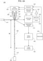
- FIGs. 1A-1C depict an integrated optofluidic interrogation module according to certain embodiments of the invention.
- integrated optofluidic interrogation module 100 includes flow cell 101 configured to transport particles in flow stream 102 (i.e., a core stream of flow stream 102).
- Integrated optofluidic interrogation module 100 has a plurality of fiber optic light conveyor couplers 111a, 111b, and 111c.
- Each fiber optic light conveyor coupler may be configured to operably attach to fiber optic light conveyors which may themselves be coupled to lasers.
- fiber optic light conveyor couplers 111a-111c may couple directly to the lasers (i.e., without intermediate fiber optics).
- module 100 also includes a focusing optical system depicted in the form of lens 114 integrated with the flow cell 101 and configured to relay excitation light from the non-circular core optical fibers to the focal spots.
- the focusing optical system may include a plurality of microlenses.
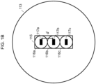
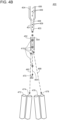
- FIG. 1B presents a view of the light emitting surface of linear fiber array 113.
- linear fiber array 113 includes a vertical stack 115 of non-circular core optical fibers 116a, 116b and 116c.
- Non-circular core optical fiber 116a is continuous with optical fiber 112a and fiber optic light conveyor coupler 111a such that laser light received at fiber optic light conveyor coupler 111a is propagated along optical fiber 112a and emitted at non-circular core optical fiber 116a.
- Non-circular core optical fiber 116b is continuous with optical fiber 112b and fiber optic light conveyor coupler 111b such that laser light received at fiber optic light conveyor coupler 111b is propagated along optical fiber 112b and emitted at non-circular core optical fiber 116b.
- Non-circular core optical fiber 116c is continuous with optical fiber 112c and fiber optic light conveyor coupler 111c such that laser light received at fiber optic light conveyor coupler 111c is propagated along optical fiber 112c and emitted at non-circular core optical fiber 116c.
- Non-circular core optical fibers 116a, 116b, and 116c include cores 117a, 117b and 117c, respectively. In the embodiment of FIG.
- cores 117a, 117b and 117c are rectangular in shape and are configured to project excitation wavelength light having a top hat profile onto the focal spots.
- Cores of adjacent non-circular core optical fibers are separated by a distance d, which in this case is determined by the cladding thickness of each of non-circular core optical fibers 116a, 116b, and 116c (i.e., the portion of non-circular core optical fibers 116a, 116b, and 116c surrounding cores 117a, 117b and 117c, respectively).
- the fiber output is mechanically and optically matched to the desired core stream positions of the respective laser excitation beams.
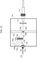
- FIG. 1C presents an embodiment of flow cell 101.
- Linear fiber array 113 projects excitation wavelength light as described above with respect to FIG. 1A and FIG. 1B . This light passes through lens 114.
- Non-circular core optical fibers 116a projects excitation wavelength light onto focal spot 126a within flow stream 102 of flow cell 101.
- Non-circular core optical fibers 116b projects excitation wavelength light onto focal spot 126b within flow stream 102 of flow cell 101.
- Non-circular core optical fibers 116c projects excitation wavelength light onto focal spot 126c within flow stream 102 of flow cell 101. Irradiation of particles in focal spots 126a-126c generates forward scatter light that propagates in a mostly forward direction.
- Forward scatter detector 123 is integrated with flow cell 101 and is configured to detect this forward scattered light. Also shown are optical mask 121 and optical filter 122 integrated with flow cell 101. Attached to forward scatter detector 123 is electrical coupler 124 for operably attaching electrical line 125 to the detector 123. In addition to forward scattered light, irradiation of particles in focal spots 126a-126c may generate side scattered and/or fluorescent light.
- a vertical stack 119 of fiber optic light collection element couplers 119a, 119b and 119c is included for operably attaching fiber optic light collection elements 120a, 120b and 120c, respectively, to flow cell 101.
- Fiber optic light collection elements 120a, 120b and 120c operably attached to fiber optic light collection element couplers 119a, 119b and 119c may be configured to convey fluorescent and/or side scatter light from focal points 126a, 126b and 126c, respectively. This light may be conveyed to one or more light detectors, as appropriate.
- Flow cytometers of interest include a plurality of light sources, and an integrated optofluidic interrogation module of the invention (e.g., described above).
- the number of light sources in the flow cytometers may vary. In some instances, the number of light sources ranges from 2 to 10, such as 2 to 5, and including 2 to 4. Any convenient light source may be employed as the light source described herein.
- the light source is a laser.
- the laser may be any convenient laser, such as a continuous wave laser.
- the laser may be a diode laser, such as an ultraviolet diode laser, a visible diode laser and a near-infrared diode laser.
- the laser may be a helium-neon (HeNe) laser.
- the laser is a gas laser, such as a helium-neon laser, argon laser, krypton laser, xenon laser, nitrogen laser, CO 2 laser, CO laser, argon-fluorine (ArF) excimer laser, krypton-fluorine (KrF) excimer laser, xenon chlorine (XeCI) excimer laser or xenon-fluorine (XeF) excimer laser or a combination thereof.
- the subject flow cytometers include a dye laser, such as a stilbene, coumarin or rhodamine laser.
- lasers of interest include a metal-vapor laser, such as a helium-cadmium (HeCd) laser, helium-mercury (HeHg) laser, helium-selenium (HeSe) laser, helium-silver (HeAg) laser, strontium laser, neon-copper (NeCu) laser, copper laser or gold laser and combinations thereof.
- a metal-vapor laser such as a helium-cadmium (HeCd) laser, helium-mercury (HeHg) laser, helium-selenium (HeSe) laser, helium-silver (HeAg) laser, strontium laser, neon-copper (NeCu) laser, copper laser or gold laser and combinations thereof.
- HeCd helium-cadmium
- HeHg helium-mercury
- HeSe helium-selenium
- HeAg helium-silver
- strontium laser neon-copper (Ne
- the subject flow cytometers include a solid-state laser, such as a ruby laser, an Nd:YAG laser, NdCrYAG laser, Er:YAG laser, Nd:YLF laser, Nd:YVO 4 laser, Nd:YCa 4 O(BO 3 ) 3 laser, Nd:YCOB laser, titanium sapphire laser, thulim YAG laser, ytterbium YAG laser, ytterbium 2 O 3 laser or cerium doped lasers and combinations thereof.
- a solid-state laser such as a ruby laser, an Nd:YAG laser, NdCrYAG laser, Er:YAG laser, Nd:YLF laser, Nd:YVO 4 laser, Nd:YCa 4 O(BO 3 ) 3 laser, Nd:YCOB laser, titanium sapphire laser, thulim YAG laser, ytterbium YAG laser, ytterbium 2 O 3 laser or cerium doped lasers and combinations thereof
- Laser light sources may also include one or more optical adjustment components.
- the optical adjustment component is located between the light source and the flow cell, and may include any device that is capable of changing the spatial width of irradiation or some other characteristic of irradiation from the light source, such as for example, irradiation direction, wavelength, beam width, beam intensity and focal spot.
- Optical adjustment protocols may include any convenient device which adjusts one or more characteristics of the light source, including but not limited to lenses, mirrors, filters, fiber optics, wavelength separators, pinholes, slits, collimating protocols and combinations thereof.
- flow cytometers of interest include one or more focusing lenses.
- the focusing lens in one example, may be a de-magnifying lens.
- flow cytometers of interest include fiber optics.
- the light source may be positioned any suitable distance from the flow cell, such as where the light source and the flow cell are separated by 0.005 mm or more, such as 0.01 mm or more, such as 0.05 mm or more, such as 0.1 mm or more, such as 0.5 mm or more, such as 1 mm or more, such as 5 mm or more, such as 10 mm or more, such as 25 mm or more and including at a distance of 100 mm or more.
- the light source may be positioned at any suitable angle relative to the flow cell, such as at an angle ranging from 10 degrees to 90 degrees, such as from 15 degrees to 85 degrees, such as from 20 degrees to 80 degrees, such as from 25 degrees to 75 degrees and including from 30 degrees to 60 degrees, for example at a 90 degree angle.
- light sources of interest include a plurality of lasers configured to provide laser light for discrete irradiation of the flow stream, such as 2 lasers or more, such as 3 lasers or more, such as 4 lasers or more, such as 5 lasers or more, such as 10 lasers or more, and including 15 lasers or more configured to provide laser light for discrete irradiation of the flow stream.
- each laser may have a specific wavelength that varies from 200 nm to 1500 nm, such as from 250 nm to 1250 nm, such as from 300 nm to 1000 nm, such as from 350 nm to 900 nm and including from 400 nm to 800 nm.
- lasers of interest may include one or more of a 405 nm laser, a 488 nm laser, a 561 nm laser and a 635 nm laser.
- Fiber optic light conveyor couplers of the linear fiber array of the integrated optofluidic interrogation module may be configured to interface directly with the lasers such that light output by the lasers travels to an appropriate optical fiber in the linear fiber array.
- flow cytometers of the invention include fiber optic light collection elements operably attached to the fiber optic light collection element couplers of the integrated optofluidic interrogation module. Details regarding fiber optic light collection elements are provided above in reference to integrated optofluidic interrogation modules of the invention.
- Flow cytometers of the invention may include light detectors operably attached to the fiber optic light collection elements.
- the light detectors are configured to detect particle-modulated light conveyed by the fiber optic light collection elements and generate signals based on a characteristic of that light (e.g., intensity).
- the one or more particle-modulated light detector(s) may include one or more side-scattered light detectors for detecting side-scatter wavelengths of light (i.e., light refracted and reflected from the surfaces and internal structures of the particle).
- modules include a single side-scattered light detector.
- modules include multiple side-scattered light detectors, such as 2 or more, such as 3 or more, such as 4 or more, and including 5 or more.
- Detectors of interest may include, but are not limited to, optical sensors or detectors, such as active-pixel sensors (APSs), avalanche photodiodes, image sensors, charge-coupled devices (CCDs), intensified charge-coupled devices (ICCDs), light emitting diodes, photon counters, bolometers, pyroelectric detectors, photoresistors, photovoltaic cells, photodiodes, photomultiplier tubes (PMTs), phototransistors, quantum dot photoconductors or photodiodes and combinations thereof, among other detectors.
- APSs active-pixel sensors
- CCDs charge-coupled devices
- ICCDs intensified charge-coupled devices
- PMTs photomultiplier tubes
- phototransistors quantum dot photoconductors or photodiodes and combinations thereof, among other detectors.
- the collected light is measured with a charge-coupled device (CCD), semiconductor charge-coupled devices (CCD), active pixel sensors (APS), complementary metal-oxide semiconductor (CMOS) image sensors or N-type metal-oxide semiconductor (NMOS) image sensors.
- the detector is a photomultiplier tube, such as a photomultiplier tube having an active detecting surface area of each region that ranges from 0.01 cm 2 to 10 cm 2 , such as from 0.05 cm 2 to 9 cm 2 , such as from 0.1 cm 2 to 8 cm 2 , such as from 0.5 cm 2 to 7 cm 2 and including from 1 cm 2 to 5 cm 2 .
- the subject modules also include a fluorescent light detector configured to detect one or more fluorescent wavelengths of light.
- modules include multiple fluorescent light detectors such as 2 or more, such as 3 or more, such as 4 or more, 5 or more, 10 or more, 15 or more, and including 20 or more.
- Detectors of interest may include, but are not limited to, optical sensors or detectors, such as active-pixel sensors (APSs), avalanche photodiodes, image sensors, charge-coupled devices (CCDs), intensified charge-coupled devices (ICCDs), light emitting diodes, photon counters, bolometers, pyroelectric detectors, photoresistors, photovoltaic cells, photodiodes, photomultiplier tubes (PMTs), phototransistors, quantum dot photoconductors or photodiodes and combinations thereof, among other detectors.
- APSs active-pixel sensors
- CCDs charge-coupled devices
- ICCDs intensified charge-coupled devices
- PMTs photomultiplier tubes
- phototransistors quantum dot photoconductors or photodiodes and combinations thereof, among other detectors.
- the collected light is measured with a charge-coupled device (CCD), semiconductor charge-coupled devices (CCD), active pixel sensors (APS), complementary metal-oxide semiconductor (CMOS) image sensors or N-type metal-oxide semiconductor (NMOS) image sensors.
- the detector is a photomultiplier tube, such as a photomultiplier tube having an active detecting surface area of each region that ranges from 0.01 cm 2 to 10 cm 2 , such as from 0.05 cm 2 to 9 cm 2 , such as from, such as from 0.1 cm 2 to 8 cm 2 , such as from 0.5 cm 2 to 7 cm 2 and including from 1 cm 2 to 5 cm 2 .
- each fluorescent light detector may be the same, or the collection of fluorescent light detectors may be a combination of different types of detectors.
- the first fluorescent light detector is a CCD-type device and the second fluorescent light detector (or imaging sensor) is a CMOS-type device.
- both the first and second fluorescent light detectors are CCD-type devices.
- both the first and second fluorescent light detectors are CMOS-type devices.
- the first fluorescent light detector is a CCD-type device and the second fluorescent light detector is a photomultiplier tube (PMT).
- the first fluorescent light detector is a CMOS-type device and the second fluorescent light detector is a photomultiplier tube.
- both the first and second fluorescent light detectors are photomultiplier tubes.
- fluorescent light detectors of interest are configured to measure collected light at one or more wavelengths, such as at 2 or more wavelengths, such as at 5 or more different wavelengths, such as at 10 or more different wavelengths, such as at 25 or more different wavelengths, such as at 50 or more different wavelengths, such as at 100 or more different wavelengths, such as at 200 or more different wavelengths, such as at 300 or more different wavelengths and including measuring light emitted by a sample in the flow stream at 400 or more different wavelengths.
- 2 or more detectors in the modules as described herein are configured to measure the same or overlapping wavelengths of collected light.
- fluorescent light detectors of interest are configured to measure collected light over a range of wavelengths (e.g., 200 nm - 1000 nm).
- detectors of interest are configured to collect spectra of light over a range of wavelengths.
- modules may include one or more detectors configured to collect spectra of light over one or more of the wavelength ranges of 200 nm - 1000 nm.
- detectors of interest are configured to measure light emitted by a sample in the flow stream at one or more specific wavelengths.
- modules may include one or more detectors configured to measure light at one or more of 450 nm, 518 nm, 519 nm, 561 nm, 578 nm, 605 nm, 607 nm, 625 nm, 650 nm, 660 nm, 667 nm, 670 nm, 668 nm, 695 nm, 710 nm, 723 nm, 780 nm, 785 nm, 647 nm, 617 nm and any combinations thereof.
- one or more detectors may be configured to be paired with specific fluorophores, such as those used with the sample in a fluorescence assay.
- embodiments of the integrated optofluidic interrogation modules of the invention include a sample fluid input coupler for injecting the flow stream into the flow cell, a sheath fluid input coupler for injecting sheath fluid into the flow cell, and/or a fluidic output coupler for receiving the flow stream from the flow cell.
- Flow cytometers may include any suitable mechanism(s) for providing sheath fluid and sample fluid to the sample fluid input coupler and sheath fluid input coupler.
- the sample fluid input coupler may be fluidically connected to a sample fluid line (e.g., tubing) fluidically connected to a sample fluid reservoir.
- sheath fluid input coupler may be fluidically connected to a sheath fluid line fluidically connected to a sheath fluid reservoir.
- flow cytometers may include any suitable mechanism(s) for managing waste from the flow stream.
- the fluidic output coupler may be fluidically connected to a waste line fluidically connected to a waste reservoir. Fluid management systems that may be adapted for use in the subject flow cytometers are provided in U.S. Patent Application Publication No. 2022/0341838 , the disclosure of which is incorporated by reference herein in its entirety.
- Suitable flow cytometry systems may include, but are not limited to those described in Ormerod (ed.), Flow Cytometry: A Practical Approach, Oxford Univ. Press (1997 ); Jaroszeski et al. (eds.), Flow Cytometry Protocols, Methods in Molecular Biology No. 91, Humana Press (1997 ); Practical Flow Cytometry, 3rd ed., Wiley-Liss (1995 ); Virgo, et al. (2012) Ann Clin Biochem. Jan;49(pt 1): 17-28 ; Linden, et. al., Semin Throm Hemost. 2004 Oct;30(5):502-11 ; Alison, et al.
- flow cytometry systems of interest include BD Biosciences FACSCanto TM flow cytometer, BD Biosciences FACSCanto TM II flow cytometer, BD Accuri TM flow cytometer, BD Accuri TM C6 Plus flow cytometer, BD Biosciences FACSCelesta TM flow cytometer, BD Biosciences FACSLyric TM flow cytometer, BD Biosciences FACSVerse TM flow cytometer, BD Biosciences FACSymphony TM flow cytometer, BD Biosciences LSRFortessa TM flow cytometer, BD Biosciences LSRFortessa TM X-20 flow cytometer, BD Biosciences FACSPresto TM flow cytometer,
- the subject systems are flow cytometric systems, such those described in U.S. Patent Nos. 10,663,476 ; 10,620,111 ; 10,613,017 ; 10,605,713 ; 10,585,031 ; 10,578,542 ; 10,578,469 ; 10,481,074 ; 10,302,545 ; 10,145,793 ; 10,113,967 ; 10,006,852 ; 9,952,076 ; 9,933,341 ; 9,726,527 ; 9,453,789 ; 9,200,334 ; 9,097,640 ; 9,095,494 ; 9,092,034 ; 8,975,595 ; 8,753,573 ; 8,233,146 ; 8,140,300 ; 7,544,326 ; 7,201,875 ; 7,129,505 ; 6,821,740 ; 6,813,017 ; 6,809,804 ; 6,372,506 ; 5,700,692 ; 5,643,796
- the particle sorter is an image enabled particle sorter.
- Image enabled particle sorters are described in U.S. Provisional Patent Application Nos. 63/431,803 and 63/465,057 ; the disclosures of which are herein incorporated by reference in their entirety.
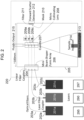
- FIG. 2 presents a schematic diagram of a flow cytometer comprising an integrated optofluidic interrogation module 220 according to certain embodiments of the invention.
- Integrated optofluidic interrogation module 220 includes flow cell 205, linear fiber array 204, focusing optical system 206 comprising a plurality of microlenses, cuvette 207, collimating lens 208, fiber optic light collection element couplers 209a-209c, optical mask 210, optical filter 211, forward scatter detector 212, sheath fluid input coupler 213, sample fluid input coupler 214, and fluidic output coupler 215.
- optical fibers 203a-203c terminate at linear fiber array 204, which is integrated with flow cell 205 and comprises a plurality of non-circular core optical fibers (e.g., described above with respect to FIG. 1B ) each configured to project excitation wavelength light onto a corresponding focal spot within cuvette 207 of flow cell 205.
- optofluidic interrogation module 220 includes a collimating lens 208 attached to an outer surface of the cuvette 207.
- Collimating lens 208 is configured to collimate particle-modulated light emitting from cuvette 207. Forward scattered light from cuvette 207 proceeds to forward scatter detector 212 after passing through optical mask 210 and optical filter 211. Side scattered and/or fluorescent light can be collected by fiber optic light collection elements (not shown) operably attached to fiber optic light collection element connectors 209a-209c.
- Sample fluid may be supplied to flow cell 205 via sample fluid input coupler 214, which may itself be fluidically connected to a sample fluid line (e.g., tubing) fluidically connected to a sample fluid reservoir. Sheath fluid may be supplied to flow cell 205 via sheath fluid input coupler 213, which may itself be fluidically connected to a sheath fluid line fluidically connected to a sheath fluid reservoir. Sheath fluid emitting from the flow cell (e.g., waste fluid) may be removed via fluidic output coupler 215. A waste line may be fluidically connected to fluidic output coupler 215, which may deposit the waste fluid in a waste reservoir.
- cytometer operation is controlled by a controller/processor 290, and the measurement data from the detectors can be stored in the memory 295 and processed by the controller/processor 290.
- the controller/processor 290 is coupled to the detectors to receive the output signals therefrom, and may also be coupled to electrical and electromechanical components of the flow cytometer to control the lasers 201a-201c, fluid flow parameters, and the like.
- Input/output (I/O) capabilities 297 may be provided also in the system.
- the memory 295, controller/processor 290, and I/O 297 may be entirely provided as an integral part of the flow cytometer.
- a display may also form part of the I/O capabilities 297 for presenting experimental data to users of the cytometer 210.
- some or all of the memory 295 and controller/processor 290 and I/O capabilities may be part of one or more external devices such as a general purpose computer.
- some or all of the memory 295 and controller/processor 290 can be in wireless or wired communication with the cytometer 210.
- the controller/processor 290 in conjunction with the memory 295 and the I/O 297 can be configured to perform various functions related to the preparation and analysis of a flow cytometer experiment.
- the I/O 297 can be configured to receive data regarding a flow cytometer experiment having a panel of fluorescent labels and a plurality of cell populations having a plurality of markers, each cell population having a subset of the plurality of markers.
- the I/O 297 can also be configured to receive biological data assigning one or more markers to one or more cell populations, marker density data, emission spectrum data, data assigning labels to one or more markers, and cytometer configuration data.
- Flow cytometer experiment data such as label spectral characteristics and flow cytometer configuration data can also be stored in the memory 295.
- the controller/processor 290 can be configured to evaluate one or more assignments of labels to markers.
- the subject flow cytometers are particle sorting systems that are configured to sort particles with an enclosed particle sorting module, such as those described in U.S. Patent Publication No. 2017/0299493, filed on March 28, 2017 , the disclosure of which is incorporated herein by reference.
- particles (e.g., cells) of the sample are sorted using a sort decision module having a plurality of sort decision units, such as those described in U.S. Patent Publication No. 2020/0256781, filed on December 23, 2019 , the disclosure of which is incorporated herein by reference.
- systems for sorting components of a sample include a particle sorting module having deflection plates, such as described in U.S. Patent Publication No. 2017/0299493, filed on March 28, 2017 , the disclosure of which is incorporated herein by reference.
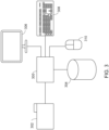
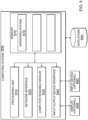
- FIG. 3 shows a functional block diagram for one example of a control system, such as a processor 300, for analyzing and displaying biological events.
- a processor 300 can be configured to implement a variety of processes for controlling graphic display of biological events.
- a flow cytometer or sorting system 302 can be configured to acquire biological event data.
- a flow cytometer can generate flow cytometric event data (e.g., particle-modulated light data).
- the flow cytometer 302 can be configured to provide biological event data to the processor 300.
- a data communication channel can be included between the flow cytometer 302 and the processor 300.
- the biological event data can be provided to the processor 300 via the data communication channel.
- the processor 300 can be configured to receive biological event data from the flow cytometer 302.
- the biological event data received from the flow cytometer 302 can include flow cytometric event data.
- the processor 300 can be configured to provide a graphical display including a first plot of biological event data to a display device 306.
- the processor 300 can be further configured to render a region of interest as a gate (e.g., a first gate) around a population of biological event data shown by the display device 306, overlaid upon the first plot, for example.
- the gate can be a logical combination of one or more graphical regions of interest drawn upon a single parameter histogram or bivariate plot.
- the display can be used to display particle parameters or saturated detector data.
- the processor 300 can be further configured to display the biological event data on the display device 306 within the gate differently from other events in the biological event data outside of the gate.
- the processor 300 can be configured to render the color of biological event data contained within the gate to be distinct from the color of biological event data outside of the gate.
- the display device 306 can be implemented as a monitor, a tablet computer, a smartphone, or other electronic device configured to present graphical interfaces.
- the processor 300 can be configured to receive a gate selection signal identifying the gate from a first input device.
- the first input device can be implemented as a mouse 310.
- the mouse 310 can initiate a gate selection signal to the processor 300 identifying the gate to be displayed on or manipulated via the display device 306 (e.g., by clicking on or in the desired gate when the cursor is positioned there).
- the first device can be implemented as the keyboard 308 or other means for providing an input signal to the processor 300 such as a touchscreen, a stylus, an optical detector, or a voice recognition system.
- Some input devices can include multiple inputting functions. In such implementations, the inputting functions can each be considered an input device.
- the mouse 310 can include a right mouse button and a left mouse button, each of which can generate a triggering event.
- the triggering event can cause the processor 300 to alter the manner in which the data is displayed, which portions of the data is actually displayed on the display device 306, and/or provide input to further processing such as selection of a population of interest for particle sorting.
- the processor 300 can be configured to detect when gate selection is initiated by the mouse 310.
- the processor 300 can be further configured to automatically modify plot visualization to facilitate the gating process. The modification can be based on the specific distribution of biological event data received by the processor 300.
- the processor 300 expands the first gate such that a second gate is generated (e.g., as discussed above).
- the processor 300 can be connected to a storage device 304.
- the storage device 304 can be configured to receive and store biological event data from the processor 300.
- the storage device 304 can also be configured to receive and store flow cytometric event data from the processor 300.
- the storage device 304 can be further configured to allow retrieval of biological event data, such as flow cytometric event data, by the processor 300.
- the display device 306 can be configured to receive display data from the processor 300.
- the display data can comprise plots of biological event data and gates outlining sections of the plots.
- the display device 306 can be further configured to alter the information presented according to input received from the processor 300 in conjunction with input from the flow cytometer 302, the storage device 304, the keyboard 308, and/or the mouse 310.
- the processor 300 can generate a user interface to receive example events for sorting.
- the user interface can include a mechanism for receiving example events or example images.
- the example events or images or an example gate can be provided prior to collection of event data for a sample or based on an initial set of events for a portion of the sample.
- FIG. 4A is a schematic drawing of a particle sorter system 400 (e.g., the flow cytometer 302) in accordance with one embodiment presented herein.
- the particle sorter system 400 is a cell sorter system.
- a drop formation transducer 402 e.g., piezo-oscillator
- a fluid conduit 401 which can be coupled to, can include, or can be, a nozzle 403.
- sheath fluid 404 hydrodynamically focuses a sample fluid 406 comprising particles 409 into a moving fluid column 408 (e.g., a stream).
- particles 409 e.g., cells
- a monitored area 411 e.g., where laser-stream intersect
- an irradiation source 412 e.g., a laser
- Vibration of the drop formation transducer 402 causes moving fluid column 408 to break into a plurality of drops 410, some of which contain particles 409.
- a detection station 414 identifies when a particle of interest (or cell of interest) crosses the monitored area 411. Detection station 414 feeds into a timing circuit 428, which in turn feeds into a flash charge circuit 430. At a drop break off point, informed by a timed drop delay ( ⁇ t), a flash charge can be applied to the moving fluid column 408 such that a drop of interest carries a charge.
- the drop of interest can include one or more particles or cells to be sorted.
- the charged drop can then be sorted by activating deflection plates (not shown) to deflect the drop into a vessel such as a collection tube or a multi- well or microwell sample plate where a well or microwell can be associated with drops of particular interest. As shown in FIG. 4A , the drops can be collected in a drain receptacle 438.
- a detection system 416 (e.g., a drop boundary detector) serves to automatically determine the phase of a drop drive signal when a particle of interest passes the monitored area 411.
- An exemplary drop boundary detector is described in U.S. Pat. No. 7,679,039 , which is incorporated herein by reference in its entirety.
- the detection system 416 allows the instrument to accurately calculate the place of each detected particle in a drop.
- the detection system 416 can feed into an amplitude signal 420 and/or phase 418 signal, which in turn feeds (via amplifier 422) into an amplitude control circuit 426 and/or frequency control circuit 424.
- the amplitude control circuit 426 and/or frequency control circuit 424 controls the drop formation transducer 402.
- the amplitude control circuit 426 and/or frequency control circuit 424 can be included in a control system.
- sort electronics e.g., the detection system 416, the detection station 414 and a processor 440
- a memory configured to store the detected events and a sort decision based thereon.
- the sort decision can be included in the event data for a particle.
- the detection system 416 and the detection station 414 can be implemented as a single detection unit or communicatively coupled such that an event measurement can be collected by one of the detection system 416 or the detection station 414 and provided to the non-collecting element.
- FIG. 4B is a schematic drawing of a particle sorter system, in accordance with one embodiment presented herein.
- the particle sorter system 400 shown in FIG. 4B includes deflection plates 452 and 454.
- a charge can be applied via a stream-charging wire in a barb. This creates a stream of droplets 410 containing particles 409 for analysis.
- the particles can be illuminated with one or more light sources (e.g., lasers) to generate light scatter and fluorescence information.
- the information for a particle is analyzed such as by sorting electronics or other detection system (not shown in FIG. 4B ).
- the deflection plates 452 and 454 can be independently controlled to attract or repel the charged droplet to guide the droplet toward a destination collection vessel (e.g., one of 472, 474, 476, or 478). As shown in FIG. 4B , the deflection plates 452 and 454 can be controlled to direct a particle along a first path 462 toward the vessel 474 or along a second path 468 toward the vessel 478. If the particle is not of interest (e.g., does not exhibit scatter or illumination information within a specified sort range), deflection plates may allow the particle to continue along a flow path 464. Such uncharged droplets may pass into a waste receptacle such as via aspirator 470.
- a destination collection vessel e.g., one of 472, 474, 476, or 478.
- the deflection plates 452 and 454 can be controlled to direct a particle along a first path 462 toward the vessel 474 or along a second path 468 toward the vessel 478. If the particle is
- FIG. 5 depicts a general architecture of an example computing device 500 according to certain embodiments.
- the general architecture of the computing device 500 depicted in FIG. 5 includes an arrangement of computer hardware and software components. It is not necessary, however, that all of these generally conventional elements be shown in order to provide an enabling disclosure.
- the computing device 500 includes a processing unit 510, a network interface 520, a computer readable medium drive 530, an input/output device interface 540, a display 550, and an input device 560, all of which may communicate with one another by way of a communication bus.
- the network interface 520 may provide connectivity to one or more networks or computing systems.
- the processing unit 510 may thus receive information and instructions from other computing systems or services via a network.
- the processing unit 510 may also communicate to and from memory 570 and further provide output information for an optional display 550 via the input/output device interface 540.
- an analysis software e.g., data analysis software or program such as FlowJo ®
- the input/output device interface 540 may also accept input from the optional input device 560, such as a keyboard, mouse, digital pen, microphone, touch screen, gesture recognition system, voice recognition system, gamepad, accelerometer, gyroscope, or other input device.
- the memory 570 may contain computer program instructions (grouped as modules or components in some embodiments) that the processing unit 510 executes in order to implement one or more embodiments.
- the memory 570 generally includes RAM, ROM and/or other persistent, auxiliary or non-transitory computer-readable media.
- the memory 570 may store an operating system 572 that provides computer program instructions for use by the processing unit 510 in the general administration and operation of the computing device 500. Data may be stored in data storage device 590.
- the memory 570 may further include computer program instructions and other information for implementing aspects of the present disclosure.
- aspects of the invention include methods of analyzing a sample.
- Methods of interest include (a) introducing a particulate sample into a flow cytometer comprising a plurality of light sources, and an integrated optofluidic interrogation module of the invention, and (b) flow cytometrically analyzing the particulate sample.
- the sample analyzed can be any sample that is of interest to a user.
- the sample contains a biological component, or is a biological sample.
- biological sample is used in its conventional sense to refer to a sample derived from or containing a whole organism, e.g., prokaryotic cells, eukaryotic cells, plants, fungi or a subset of animal tissues, cells or component parts which may in certain instances be found in blood, mucus, lymphatic fluid, synovial fluid, cerebrospinal fluid, saliva, bronchoalveolar lavage, amniotic fluid, amniotic cord blood, urine, vaginal fluid and semen.
- a "biological sample” refers to both the native organism or a subset of its tissues as well as to: a homogenate; isolated, purified or enriched biological particles (e.g., DNA, RNA, proteins, sub-cellular organelles, etc.); and lysates or extracts prepared from the organism or a subset of its tissues, including but not limited to, for example, plasma, serum, spinal fluid, lymph fluid, sections of the skin, respiratory, gastrointestinal, cardiovascular, and genitourinary tracts, tears, saliva, milk, blood cells, tumors, organs.
- Biological samples may be any type of organismic tissue, including both healthy and diseased tissue (e.g., cancerous, malignant, necrotic, etc.).
- the biological sample is a liquid sample, such as blood or derivative thereof, e.g., plasma, tears, urine, semen, etc., where in some instances the sample is a blood sample, including whole blood, such as blood obtained from venipuncture or fingerstick (where the blood may or may not be combined with any reagents prior to assay, such as preservatives, anticoagulants, etc.).
- a liquid sample such as blood or derivative thereof, e.g., plasma, tears, urine, semen, etc.
- the sample is a blood sample, including whole blood, such as blood obtained from venipuncture or fingerstick (where the blood may or may not be combined with any reagents prior to assay, such as preservatives, anticoagulants, etc.).
- the source of the sample is a "mammal” or “mammalian”, where these terms are used broadly to describe organisms which are within the class Mammalia, including the orders carnivore (e.g., dogs and cats), Rodentia (e.g., mice, guinea pigs, and rats), and primates (e.g., humans, chimpanzees, and monkeys). In some instances, the subjects are humans.
- the methods may be applied to samples obtained from human subjects of both genders and at any stage of development (i.e., neonates, infant, juvenile, adolescent, adult), where in certain embodiments the human subject is a juvenile, adolescent or adult.
- Methods of interest may further include employing particles in research, laboratory testing, or therapy.
- the subject methods include obtaining individual cells prepared from a target fluidic or tissue biological sample.
- the subject methods include obtaining cells from fluidic or tissue samples to be used as a research or diagnostic specimen for diseases such as cancer.
- the subject methods include obtaining cells from fluidic or tissue samples to be used in therapy.
- a cell therapy protocol is a protocol in which viable cellular material including, e.g., cells and tissues, may be prepared and introduced into a subject as a therapeutic treatment. Conditions that may be treated by the administration of the flow cytometrically sorted sample include, but are not limited to, blood disorders, immune system disorders, organ damage, etc.
- cell enrichment may occur via several methods including, e.g., centrifugation based methods, filter based methods, elutriation, magnetic separation methods, fluorescence-activated cell sorting (FACS), and the like.
- the enriched cells may be genetically modified by any convenient method, e.g., nuclease mediated gene editing.
- the genetically modified cells can be cultured, activated, and expanded in vitro.
- the cells are preserved, e.g., cryopreserved, and stored for future use where the cells are thawed and then administered to a patient, e.g., the cells may be infused in the patient.
- aspects of the invention additionally include methods of assembling a flow cytometer.
- Methods of interest include (a) positioning an integrated optofluidic interrogation module into a flow cytometer comprising a plurality of light sources, and (b) operably attaching the plurality of fiber optic light conveyor couplers to the plurality of light sources to assemble the flow cytometer.
- integrated optofluidic interrogation modules of the present disclosure include a flow cell comprising a light-accessible flow channel for transporting particles in a flow stream, a linear fiber array integrated with the flow cell and comprising a plurality of non-circular core optical fibers each configured to project excitation wavelength light onto a corresponding focal spot within the flow cell, and a plurality of fiber optic light conveyor couplers for operably attaching the plurality of light sources to the linear fiber array.
- embodiments of the integrated optofluidic interrogation modules include a light detector integrated with the flow cell and an electrical coupler for operably attaching an electrical line to the light detector.
- assembling the flow cytometer includes operably attaching the electrical line to the electrical coupler.
- embodiments of the integrated optofluidic interrogation modules include a plurality of fiber optic light collection element couplers for operably attaching a plurality of fiber optic light collection elements to the flow cell.
- assembling the flow cytometer includes operably attaching the plurality of fiber optic light collection elements to the plurality of fiber optic light collection element couplers.
- modules include a sample fluid input coupler for injecting the flow stream into the flow cell
- some implementations of the disclosed methods involve fluidically connecting a sample fluid line of the flow cytometer to the sample fluid input coupler.
- modules include a sheath fluid input coupler for injecting sheath fluid into the flow cell
- some implementations of the disclosed methods involve fluidically connecting a sheath fluid line of the flow cytometer to the sheath fluid input coupler.
- modules include a fluidic output coupler for receiving the flow stream from the flow cell
- some implementations of the disclosed methods include fluidically connecting a waste line of the flow cytometer to the fluidic output coupler.
- the methods of assembling a flow cytometer disclosed herein do not include mechanical mounting and alignment.
- the optical components are already precisely optically aligned when the integrated optofluidic interrogation module is positioned within the flow cytometer and connected to the relevant components (e.g., lasers, fiber optic light collection elements, electrical line, etc.) by virtue of the integrated nature of the module.
- methods of the invention result in an assembly and/or alignment time that is 20% or less than conventional methods not involving integrated optics, such as 30% or less, such as 50% or less and including 60% or less.
- kits of interest include an integrated optofluidic interrogation module (e.g., described above).
- Embodiments of the subject kits include a single integrated optofluidic interrogation module.
- kits include a plurality of integrated optofluidic interrogation modules.
- the number of integrated optofluidic interrogation modules in the subject kits may range from 2 to 20, such as 2 to 10, and including 2 to 5.
- Kits may additionally include one or more other components useful for assembling a flow cytometer.
- kits include one or more electrical lines for transmitting signals generated by a light detector integrated with the flow cell.
- kits include a plurality of electrical lines, such as 2 or more electrical lines, such as 3 or more electrical lines, such as 4 or more electrical lines, and including 5 or more electrical lines.
- Kits according to some embodiments include a plurality of fiber optic light collection elements. For example, the number of fiber optic light collection elements may range from 2 to 20, such as 2 to 10.
- kits include fluidic components such as sample fluid lines, sheath fluid lines, and/or waste lines that may be operable attached to the modules.
- Kits may further include instructions for practicing the subject methods. These instructions may be present in the subject kits in a variety of forms, one or more of which may be present in the kit.
- One form in which these instructions may be present is as printed information on a suitable medium or substrate, e.g., a piece or pieces of paper on which the information is printed, in the packaging of the kit, in a package insert, and the like.
- Yet another form of these instructions is a computer readable medium, e.g., diskette, compact disk (CD), portable flash drive, and the like, on which the information has been recorded.
- Yet another form of these instructions that may be present is a website address which may be used via the internet to access the information at a removed site.
- the subject integrated optofluidic interrogation modules, flow cytometers and methods find use in find use in a variety of applications where it is desirable to increase resolution and accuracy in the determination of parameters for analytes (e.g., cells, particles) in a biological sample.
- analytes e.g., cells, particles
- the present invention may be employed in order to facilitate flow cytometer assembly, i.e., such that tedious assembly and adjustment is not required.
- the subject integrated optofluidic interrogation modules, flow cytometers and methods find use where it is desirable to simplify complex flow cytometer assembly that would normally include painstaking mechanical mounting and alignment.
- the subject integrated optofluidic interrogation modules, flow cytometers and methods may consequently be used to decrease the cost of flow cytometer assembly and improve the robustness of results obtained from flow cytometry.
- the present invention may be employed where it is desirable to have modular flow cytometer components, i.e., such that components can be swapped for different modules as required to achieve a functionality of interest.
- the present invention may be employed where it is desirable to improve flow cytometer collection efficiency.
- the present disclosure can be employed to characterize many types of analytes, in particular, analytes relevant to medical diagnosis or protocols for caring for a patient, including but not limited to: proteins (including both free proteins and proteins and proteins bound to the surface of a structure, such as a cell), nucleic acids, viral particles, and the like. Further, samples can be from in vitro or in vivo sources, and samples can be diagnostic samples.
- FIG. 6 An irradiance profile was obtained for light emitted by a linear fiber array arranged as described in FIG. 1B .
- the resulting irradiance profile is shown in FIG. 6 .
- irradiance is uniform and regularly spaced indicating that the linear fiber array is suitable for use in irradiating the core stream.
Landscapes
- Chemical & Material Sciences (AREA)
- Dispersion Chemistry (AREA)
- Physics & Mathematics (AREA)
- Health & Medical Sciences (AREA)
- Life Sciences & Earth Sciences (AREA)
- Analytical Chemistry (AREA)
- Biochemistry (AREA)
- General Health & Medical Sciences (AREA)
- General Physics & Mathematics (AREA)
- Immunology (AREA)
- Pathology (AREA)
- Investigating, Analyzing Materials By Fluorescence Or Luminescence (AREA)
- Optical Measuring Cells (AREA)
Applications Claiming Priority (1)
| Application Number | Priority Date | Filing Date | Title |
|---|---|---|---|
| US202363537165P | 2023-09-07 | 2023-09-07 |
Publications (1)
| Publication Number | Publication Date |
|---|---|
| EP4521097A1 true EP4521097A1 (de) | 2025-03-12 |
Family
ID=92675820
Family Applications (1)
| Application Number | Title | Priority Date | Filing Date |
|---|---|---|---|
| EP24198380.8A Pending EP4521097A1 (de) | 2023-09-07 | 2024-09-04 | Integrierte optofluidische abfragemodule, durchflusszytometer damit und verfahren zur verwendung davon |
Country Status (4)
| Country | Link |
|---|---|
| US (1) | US20250085212A1 (de) |
| EP (1) | EP4521097A1 (de) |
| JP (1) | JP2025041555A (de) |
| CN (1) | CN119574408A (de) |
Families Citing this family (2)
| Publication number | Priority date | Publication date | Assignee | Title |
|---|---|---|---|---|
| US12535408B2 (en) | 2024-04-16 | 2026-01-27 | Vuv Analytics, Inc. | Spectroscopy systems and methods for analyzing liquids at vacuum ultraviolet (VUV) wavelengths |
| US20250321182A1 (en) * | 2024-04-16 | 2025-10-16 | Vuv Analytics, Inc. | Flow Cells And Methods For Analyzing Liquids At Vacuum Ultraviolet (VUV) Wavelengths |
Citations (41)
| Publication number | Priority date | Publication date | Assignee | Title |
|---|---|---|---|---|
| US4498766A (en) | 1982-03-25 | 1985-02-12 | Becton, Dickinson And Company | Light beam focal spot elongation in flow cytometry devices |
| US4987086A (en) | 1987-11-30 | 1991-01-22 | Becton, Dickinson And Company | Method for analysis of subpopulations of cells |
| US5602039A (en) | 1994-10-14 | 1997-02-11 | The University Of Washington | Flow cytometer jet monitor system |
| US5620842A (en) | 1995-03-29 | 1997-04-15 | Becton Dickinson And Company | Determination of the number of fluorescent molecules on calibration beads for flow cytometry |
| US5627040A (en) | 1991-08-28 | 1997-05-06 | Becton Dickinson And Company | Flow cytometric method for autoclustering cells |
| US5643796A (en) | 1994-10-14 | 1997-07-01 | University Of Washington | System for sensing droplet formation time delay in a flow cytometer |
| US5700692A (en) | 1994-09-27 | 1997-12-23 | Becton Dickinson And Company | Flow sorter with video-regulated droplet spacing |
| US6372506B1 (en) | 1999-07-02 | 2002-04-16 | Becton, Dickinson And Company | Apparatus and method for verifying drop delay in a flow cytometer |
| US6809804B1 (en) | 2000-05-11 | 2004-10-26 | Becton, Dickinson And Company | System and method for providing improved event reading and data processing capabilities in a flow cytometer |
| US6813017B1 (en) | 1999-10-20 | 2004-11-02 | Becton, Dickinson And Company | Apparatus and method employing incoherent light emitting semiconductor devices as particle detection light sources in a flow cytometer |
| US6821740B2 (en) | 1998-02-25 | 2004-11-23 | Becton, Dickinson And Company | Flow cytometric methods for the concurrent detection of discrete functional conformations of PRB in single cells |
| US7129505B2 (en) | 2001-08-28 | 2006-10-31 | Becton Dickinson And Company | Fluorescence detection instrument with reflective transfer legs for color decimation |
| US7201875B2 (en) | 2002-09-27 | 2007-04-10 | Becton Dickinson And Company | Fixed mounted sorting cuvette with user replaceable nozzle |
| US7679039B2 (en) | 2002-04-24 | 2010-03-16 | The Institute For Systems Biology | Compositions and methods for drop boundary detection and radiation beam alignment |
| US8140300B2 (en) | 2008-05-15 | 2012-03-20 | Becton, Dickinson And Company | High throughput flow cytometer operation with data quality assessment and control |
| US8233146B2 (en) | 2009-01-13 | 2012-07-31 | Becton, Dickinson And Company | Cuvette for flow-type particle analyzer |
| US8753573B2 (en) | 2011-04-29 | 2014-06-17 | Becton, Dickinson And Company | Multi-way sorter system and method |
| US8975595B2 (en) | 2013-04-12 | 2015-03-10 | Becton, Dickinson And Company | Automated set-up for cell sorting |
| US9092034B2 (en) | 2010-10-29 | 2015-07-28 | Becton, Dickinson And Company | Dual feedback vacuum fluidics for a flow-type particle analyzer |
| US9097640B2 (en) | 2007-01-26 | 2015-08-04 | Becton, Dickinson And Company | Method, system, and compositions for cell counting and analysis |
| US9095494B2 (en) | 2011-09-30 | 2015-08-04 | Becton, Dickinson And Company | Fluid exchange methods and devices |
| US9200334B2 (en) | 2011-04-29 | 2015-12-01 | Becton, Dickinson And Company | Cell sorter system and method |
| US20170299493A1 (en) | 2016-04-15 | 2017-10-19 | Becton, Dickinson And Company | Enclosed droplet sorter and methods of using the same |
| US9933341B2 (en) | 2012-04-05 | 2018-04-03 | Becton, Dickinson And Company | Sample preparation for flow cytometry |
| US10006852B2 (en) | 2016-09-13 | 2018-06-26 | Becton, Dickinson And Company | Flow cytometer with optical equalization |
| US10113967B2 (en) | 2011-06-24 | 2018-10-30 | Becton, Dickinson And Company | Absorbance sprectrum scanning flow cytometry |
| US10145793B2 (en) | 2015-07-15 | 2018-12-04 | Becton, Dickinson And Company | System and method for adjusting cytometer measurements |
| US10302545B2 (en) | 2015-10-05 | 2019-05-28 | Becton, Dickinson And Company | Automated drop delay calculation |
| US10481074B2 (en) | 2010-10-25 | 2019-11-19 | Becton, Dickinson And Company | Systems and user interface for collecting a data set in a flow cytometer |
| US10578542B2 (en) | 2017-10-16 | 2020-03-03 | Becton, Dickinson And Company | Multi-photon counting for high sensitivity flow cytometer systems and methods for using the same |
| US10585031B2 (en) | 2017-02-27 | 2020-03-10 | Becton, Dickinson And Company | Light detection systems and methods for using thereof |
| US10605713B2 (en) | 2016-10-05 | 2020-03-31 | Becton, Dickinson And Company | Droplet deflectors and methods for using the same |
| US10613017B2 (en) | 2018-04-26 | 2020-04-07 | Becton, Dickinson And Company | Biexponential transformation for particle sorters |
| US10620111B2 (en) | 2016-03-17 | 2020-04-14 | Becton, Dickinson And Company | Cell sorting using a high throughput fluorescence flow cytometer |
| US10663476B2 (en) | 2013-11-13 | 2020-05-26 | Becton, Dickinson And Company | Optical imaging system and methods for using the same |
| US20200256781A1 (en) | 2019-02-08 | 2020-08-13 | Becton, Dickinson And Company | Droplet sorting decision modules, systems and methods of use thereof |
| US20220120658A1 (en) * | 2020-10-20 | 2022-04-21 | Becton, Dickinson And Company | Flow cytometers including tilted beam shaping optical components, and methods of using the same |
| US20220236165A1 (en) | 2021-01-27 | 2022-07-28 | Becton, Dickinson And Company | Flow cytometers including fiber optic light collectors, and methods of use thereof |
| US20220244166A1 (en) * | 2021-02-04 | 2022-08-04 | Becton, Dickinson And Company | Integrated light interrogation modules and methods of use thereof |
| US20220341838A1 (en) | 2021-04-23 | 2022-10-27 | Becton, Dickinson And Company | Fluid management system for an analyzer and/or sorter type flow type particle analyzer |
| US20230046207A1 (en) | 2021-08-10 | 2023-02-16 | Becton, Dickinson And Company | Outlet fittings for reducing bubbles at the interface with a flow cell, and flow cytometers and methods using the same |
-
2024
- 2024-08-27 US US18/816,927 patent/US20250085212A1/en active Pending
- 2024-09-04 EP EP24198380.8A patent/EP4521097A1/de active Pending
- 2024-09-06 CN CN202411247548.6A patent/CN119574408A/zh active Pending
- 2024-09-06 JP JP2024154236A patent/JP2025041555A/ja active Pending
Patent Citations (46)
| Publication number | Priority date | Publication date | Assignee | Title |
|---|---|---|---|---|
| US4498766A (en) | 1982-03-25 | 1985-02-12 | Becton, Dickinson And Company | Light beam focal spot elongation in flow cytometry devices |
| US4987086A (en) | 1987-11-30 | 1991-01-22 | Becton, Dickinson And Company | Method for analysis of subpopulations of cells |
| US5627040A (en) | 1991-08-28 | 1997-05-06 | Becton Dickinson And Company | Flow cytometric method for autoclustering cells |
| US5700692A (en) | 1994-09-27 | 1997-12-23 | Becton Dickinson And Company | Flow sorter with video-regulated droplet spacing |
| US5602039A (en) | 1994-10-14 | 1997-02-11 | The University Of Washington | Flow cytometer jet monitor system |
| US5643796A (en) | 1994-10-14 | 1997-07-01 | University Of Washington | System for sensing droplet formation time delay in a flow cytometer |
| US5620842A (en) | 1995-03-29 | 1997-04-15 | Becton Dickinson And Company | Determination of the number of fluorescent molecules on calibration beads for flow cytometry |
| US6821740B2 (en) | 1998-02-25 | 2004-11-23 | Becton, Dickinson And Company | Flow cytometric methods for the concurrent detection of discrete functional conformations of PRB in single cells |
| US6372506B1 (en) | 1999-07-02 | 2002-04-16 | Becton, Dickinson And Company | Apparatus and method for verifying drop delay in a flow cytometer |
| US6813017B1 (en) | 1999-10-20 | 2004-11-02 | Becton, Dickinson And Company | Apparatus and method employing incoherent light emitting semiconductor devices as particle detection light sources in a flow cytometer |
| US6809804B1 (en) | 2000-05-11 | 2004-10-26 | Becton, Dickinson And Company | System and method for providing improved event reading and data processing capabilities in a flow cytometer |
| US7129505B2 (en) | 2001-08-28 | 2006-10-31 | Becton Dickinson And Company | Fluorescence detection instrument with reflective transfer legs for color decimation |
| US7679039B2 (en) | 2002-04-24 | 2010-03-16 | The Institute For Systems Biology | Compositions and methods for drop boundary detection and radiation beam alignment |
| US7201875B2 (en) | 2002-09-27 | 2007-04-10 | Becton Dickinson And Company | Fixed mounted sorting cuvette with user replaceable nozzle |
| US7544326B2 (en) | 2002-09-27 | 2009-06-09 | Becton, Dickinson And Company | Fixed mounted sorting cuvette with user replaceable nozzle |
| US9097640B2 (en) | 2007-01-26 | 2015-08-04 | Becton, Dickinson And Company | Method, system, and compositions for cell counting and analysis |
| US8140300B2 (en) | 2008-05-15 | 2012-03-20 | Becton, Dickinson And Company | High throughput flow cytometer operation with data quality assessment and control |
| US8233146B2 (en) | 2009-01-13 | 2012-07-31 | Becton, Dickinson And Company | Cuvette for flow-type particle analyzer |
| US10481074B2 (en) | 2010-10-25 | 2019-11-19 | Becton, Dickinson And Company | Systems and user interface for collecting a data set in a flow cytometer |
| US9092034B2 (en) | 2010-10-29 | 2015-07-28 | Becton, Dickinson And Company | Dual feedback vacuum fluidics for a flow-type particle analyzer |
| US9200334B2 (en) | 2011-04-29 | 2015-12-01 | Becton, Dickinson And Company | Cell sorter system and method |
| US8753573B2 (en) | 2011-04-29 | 2014-06-17 | Becton, Dickinson And Company | Multi-way sorter system and method |
| US9453789B2 (en) | 2011-04-29 | 2016-09-27 | Becton, Dickinson And Company | Cell sorter system and method |
| US10113967B2 (en) | 2011-06-24 | 2018-10-30 | Becton, Dickinson And Company | Absorbance sprectrum scanning flow cytometry |
| US9095494B2 (en) | 2011-09-30 | 2015-08-04 | Becton, Dickinson And Company | Fluid exchange methods and devices |
| US9933341B2 (en) | 2012-04-05 | 2018-04-03 | Becton, Dickinson And Company | Sample preparation for flow cytometry |
| US8975595B2 (en) | 2013-04-12 | 2015-03-10 | Becton, Dickinson And Company | Automated set-up for cell sorting |
| US9726527B2 (en) | 2013-04-12 | 2017-08-08 | Becton, Dickinson And Company | Automated set-up for cell sorting |
| US9952076B2 (en) | 2013-04-12 | 2018-04-24 | Becton, Dickinson And Company | Automated set-up for cell sorting |
| US10578469B2 (en) | 2013-04-12 | 2020-03-03 | Becton, Dickinson And Company | Automated set-up for cell sorting |
| US10663476B2 (en) | 2013-11-13 | 2020-05-26 | Becton, Dickinson And Company | Optical imaging system and methods for using the same |
| US10145793B2 (en) | 2015-07-15 | 2018-12-04 | Becton, Dickinson And Company | System and method for adjusting cytometer measurements |
| US10302545B2 (en) | 2015-10-05 | 2019-05-28 | Becton, Dickinson And Company | Automated drop delay calculation |
| US10620111B2 (en) | 2016-03-17 | 2020-04-14 | Becton, Dickinson And Company | Cell sorting using a high throughput fluorescence flow cytometer |
| US20170299493A1 (en) | 2016-04-15 | 2017-10-19 | Becton, Dickinson And Company | Enclosed droplet sorter and methods of using the same |
| US10006852B2 (en) | 2016-09-13 | 2018-06-26 | Becton, Dickinson And Company | Flow cytometer with optical equalization |
| US10605713B2 (en) | 2016-10-05 | 2020-03-31 | Becton, Dickinson And Company | Droplet deflectors and methods for using the same |
| US10585031B2 (en) | 2017-02-27 | 2020-03-10 | Becton, Dickinson And Company | Light detection systems and methods for using thereof |
| US10578542B2 (en) | 2017-10-16 | 2020-03-03 | Becton, Dickinson And Company | Multi-photon counting for high sensitivity flow cytometer systems and methods for using the same |
| US10613017B2 (en) | 2018-04-26 | 2020-04-07 | Becton, Dickinson And Company | Biexponential transformation for particle sorters |
| US20200256781A1 (en) | 2019-02-08 | 2020-08-13 | Becton, Dickinson And Company | Droplet sorting decision modules, systems and methods of use thereof |
| US20220120658A1 (en) * | 2020-10-20 | 2022-04-21 | Becton, Dickinson And Company | Flow cytometers including tilted beam shaping optical components, and methods of using the same |
| US20220236165A1 (en) | 2021-01-27 | 2022-07-28 | Becton, Dickinson And Company | Flow cytometers including fiber optic light collectors, and methods of use thereof |
| US20220244166A1 (en) * | 2021-02-04 | 2022-08-04 | Becton, Dickinson And Company | Integrated light interrogation modules and methods of use thereof |
| US20220341838A1 (en) | 2021-04-23 | 2022-10-27 | Becton, Dickinson And Company | Fluid management system for an analyzer and/or sorter type flow type particle analyzer |
| US20230046207A1 (en) | 2021-08-10 | 2023-02-16 | Becton, Dickinson And Company | Outlet fittings for reducing bubbles at the interface with a flow cell, and flow cytometers and methods using the same |
Non-Patent Citations (7)
| Title |
|---|
| "Flow Cytometry: A Practical Approach", 1997, OXFORD UNIV. PRESS, article "Flow Cytometry Protocols" |
| ALISON ET AL., J PATHOL, vol. 222, no. 4, December 2010 (2010-12-01), pages 335 - 344 |
| HERBIG ET AL., CRIT REV THER DRUG CARRIER SYST, vol. 24, no. 3, 2007, pages 203 - 255 |
| HRACEK, BBÄUERLE, H, OPTIK & PHOTONIK, vol. 10, no. 5, 2015, pages 16 - 18 |
| LINDEN, SEMIN THROM HEMOST, vol. 30, no. 5, October 2004 (2004-10-01), pages 502 - 11 |
| PRACTICAL: "Flow Cytometry", 1995, WILEY-LISS |
| VIRGO ET AL., ANN CLIN BIOCHEM., vol. 49, January 2012 (2012-01-01), pages 17 - 28 |
Also Published As
| Publication number | Publication date |
|---|---|
| US20250085212A1 (en) | 2025-03-13 |
| CN119574408A (zh) | 2025-03-07 |
| JP2025041555A (ja) | 2025-03-26 |
Similar Documents
| Publication | Publication Date | Title |
|---|---|---|
| EP4521097A1 (de) | Integrierte optofluidische abfragemodule, durchflusszytometer damit und verfahren zur verwendung davon | |
| US12436086B2 (en) | Flow cytometers including fiber optic light collectors, and methods of use thereof | |
| US20250327733A1 (en) | Clamps for Applying An Immobilizing Force To A Photodetector, and Systems and Methods for Using The Same | |
| US11994458B2 (en) | Integrated light interrogation modules and methods of use thereof | |
| US20250314576A1 (en) | Light Detection Systems Having First and Second Light Receivers, and Methods of Use Thereof | |
| US20250067655A1 (en) | Outlet fittings for reducing bubbles at the interface with a flow cell, and flow cytometers and methods using the same | |
| US12467845B2 (en) | Clamps for operably coupling an optical component to a mounting block, and methods and systems for using the same | |
| US20250341455A1 (en) | Flow cells having an optimized flow channel geometry, flow cytometers including the same, and methods of use thereof | |
| US20230375458A1 (en) | Particle sorter nozzles and methods of use thereof | |
| US12546797B2 (en) | Flow cytometers including sample injection needles, and methods of use thereof | |
| US12480859B2 (en) | Methods and systems for evaluating flow cytometer data for the presence of a coincident event | |
| US12287274B2 (en) | Fluidic resistance units, as well as flow cytometers and methods involving the same |
Legal Events
| Date | Code | Title | Description |
|---|---|---|---|
| PUAI | Public reference made under article 153(3) epc to a published international application that has entered the european phase |
Free format text: ORIGINAL CODE: 0009012 |
|
| STAA | Information on the status of an ep patent application or granted ep patent |
Free format text: STATUS: THE APPLICATION HAS BEEN PUBLISHED |
|
| AK | Designated contracting states |
Kind code of ref document: A1 Designated state(s): AL AT BE BG CH CY CZ DE DK EE ES FI FR GB GR HR HU IE IS IT LI LT LU LV MC ME MK MT NL NO PL PT RO RS SE SI SK SM TR |
|
| STAA | Information on the status of an ep patent application or granted ep patent |
Free format text: STATUS: REQUEST FOR EXAMINATION WAS MADE |
|
| 17P | Request for examination filed |
Effective date: 20250827 |