EP4521080A1 - Detektionssensor - Google Patents
Detektionssensor Download PDFInfo
- Publication number
- EP4521080A1 EP4521080A1 EP24194738.1A EP24194738A EP4521080A1 EP 4521080 A1 EP4521080 A1 EP 4521080A1 EP 24194738 A EP24194738 A EP 24194738A EP 4521080 A1 EP4521080 A1 EP 4521080A1
- Authority
- EP
- European Patent Office
- Prior art keywords
- case
- hole
- sound
- front portion
- detection sensor
- Prior art date
- Legal status (The legal status is an assumption and is not a legal conclusion. Google has not performed a legal analysis and makes no representation as to the accuracy of the status listed.)
- Granted
Links
Images


Classifications
-
- G—PHYSICS
- G01—MEASURING; TESTING
- G01J—MEASUREMENT OF INTENSITY, VELOCITY, SPECTRAL CONTENT, POLARISATION, PHASE OR PULSE CHARACTERISTICS OF INFRARED, VISIBLE OR ULTRAVIOLET LIGHT; COLORIMETRY; RADIATION PYROMETRY
- G01J5/00—Radiation pyrometry, e.g. infrared or optical thermometry
- G01J5/10—Radiation pyrometry, e.g. infrared or optical thermometry using electric radiation detectors
- G01J5/34—Radiation pyrometry, e.g. infrared or optical thermometry using electric radiation detectors using capacitors, e.g. pyroelectric capacitors
-
- G—PHYSICS
- G01—MEASURING; TESTING
- G01H—MEASUREMENT OF MECHANICAL VIBRATIONS OR ULTRASONIC, SONIC OR INFRASONIC WAVES
- G01H11/00—Measuring mechanical vibrations or ultrasonic, sonic or infrasonic waves by detecting changes in electric or magnetic properties
- G01H11/06—Measuring mechanical vibrations or ultrasonic, sonic or infrasonic waves by detecting changes in electric or magnetic properties by electric means
- G01H11/08—Measuring mechanical vibrations or ultrasonic, sonic or infrasonic waves by detecting changes in electric or magnetic properties by electric means using piezoelectric devices
-
- G—PHYSICS
- G01—MEASURING; TESTING
- G01D—MEASURING NOT SPECIALLY ADAPTED FOR A SPECIFIC VARIABLE; ARRANGEMENTS FOR MEASURING TWO OR MORE VARIABLES NOT COVERED IN A SINGLE OTHER SUBCLASS; TARIFF METERING APPARATUS; MEASURING OR TESTING NOT OTHERWISE PROVIDED FOR
- G01D5/00—Mechanical means for transferring the output of a sensing member; Means for converting the output of a sensing member to another variable where the form or nature of the sensing member does not constrain the means for converting; Transducers not specially adapted for a specific variable
- G01D5/12—Mechanical means for transferring the output of a sensing member; Means for converting the output of a sensing member to another variable where the form or nature of the sensing member does not constrain the means for converting; Transducers not specially adapted for a specific variable using electric or magnetic means
- G01D5/14—Mechanical means for transferring the output of a sensing member; Means for converting the output of a sensing member to another variable where the form or nature of the sensing member does not constrain the means for converting; Transducers not specially adapted for a specific variable using electric or magnetic means influencing the magnitude of a current or voltage
-
- G—PHYSICS
- G01—MEASURING; TESTING
- G01D—MEASURING NOT SPECIALLY ADAPTED FOR A SPECIFIC VARIABLE; ARRANGEMENTS FOR MEASURING TWO OR MORE VARIABLES NOT COVERED IN A SINGLE OTHER SUBCLASS; TARIFF METERING APPARATUS; MEASURING OR TESTING NOT OTHERWISE PROVIDED FOR
- G01D11/00—Component parts of measuring arrangements not specially adapted for a specific variable
- G01D11/24—Housings ; Casings for instruments
-
- G—PHYSICS
- G01—MEASURING; TESTING
- G01J—MEASUREMENT OF INTENSITY, VELOCITY, SPECTRAL CONTENT, POLARISATION, PHASE OR PULSE CHARACTERISTICS OF INFRARED, VISIBLE OR ULTRAVIOLET LIGHT; COLORIMETRY; RADIATION PYROMETRY
- G01J5/00—Radiation pyrometry, e.g. infrared or optical thermometry
- G01J5/02—Constructional details
- G01J5/04—Casings
- G01J5/041—Mountings in enclosures or in a particular environment
- G01J5/045—Sealings; Vacuum enclosures; Encapsulated packages; Wafer bonding structures; Getter arrangements
-
- H—ELECTRICITY
- H04—ELECTRIC COMMUNICATION TECHNIQUE
- H04R—LOUDSPEAKERS, MICROPHONES, GRAMOPHONE PICK-UPS OR LIKE ACOUSTIC ELECTROMECHANICAL TRANSDUCERS; ELECTRIC HEARING AIDS; PUBLIC ADDRESS SYSTEMS
- H04R17/00—Piezoelectric transducers; Electrostrictive transducers
- H04R17/02—Microphones
- H04R17/025—Microphones using a piezoelectric polymer
Definitions
- the invention relates to detection sensors.
- the second detection sensor includes a shield case, an electrically conductive support, and a piezoelectric polymer film.
- the shield case has an opening open to one side in a first direction.
- the support is securely accommodated inside the shield case and disposed on the other side in the first direction relative to the opening.
- the piezoelectric polymer film is supported on the support and disposed on the other side in the first direction relative to the opening.
- the piezoelectric polymer film is exposed from the opening to the one side in the first direction.
- the piezoelectric polymer film is irradiated with infrared rays from the one side in the first direction through the opening and generate signals through a pyroelectric effect, and also vibrated by sound waves inputted from the one side in the first direction through the opening and thereby generate a signal.
- the piezoelectric polymer film is exposed from the opening, there is a possibility that dust, dirt, water, and the like adhere to the piezoelectric polymer film.
- the invention provides a detection sensor that can receive input of infrared rays and input of sound waves from the same direction and does not expose a vibratable film to outside.
- a detection sensor includes a sensor unit and a holder.
- the sensor unit includes a vibratable film constituted by a piezoelectric film and a case accommodating the vibratable film.
- the vibratable film is configured to be irradiated with infrared rays and thereby generate first electric signals through a pyroelectric effect, and configured to be vibrated by sound waves and thereby generate second electric signals through a piezoelectric effect.
- the case includes an opening disposed on one side in a first direction relative to the vibratable film. The first direction is a thickness direction of the vibratable film.
- the holder includes a holding portion holding the sensor unit, a front portion disposed on the one side in the first direction relative to the case, a transmissive part configured to transmit at least infrared rays, a sound hole to input therethrough sound waves, and a sound path.
- the transmissive part is provided at the front portion, exposed from the front portion to the one side and the other side in the first direction, disposed on the one side in the first direction relative to the opening and the vibratable film, and opposed to the vibratable film.
- the sound hole is provided in a portion around the transmissive part of the front portion and open to the one side in the first direction. The sound path extends from the sound hole to the opening of the case.
- the detection sensor of the above aspect can receive input of infrared ray and input of sound waves from the same direction for the following reasons.
- the front portion of the holder is disposed on the one side in the first direction relative to the case of the sensor unit.
- the transmissive part of the holder is provided at the front portion of the holder, exposed from the front portion to the one side and the other side in the first direction, disposed on the one side in the first direction relative to the opening and the vibratable film of the sensor unit, and opposed to the vibratable film. This arrangement allows at least infrared rays to transmit through the transmissive part from the one side in the first direction and be projected onto the vibratable film of the sensor unit.
- the sound hole is provided in the portion around the transmissive part of the front portion and the sound path extends from the sound hole to the opening of the case, sound waves can also enter into the sound hole from the one side in the first direction, pass through the sound hole, the sound path, and the opening, and vibrate the vibratable film.
- the transmissive part of the holder is provided at the front portion of the holder and opposed to the vibratable film while the sound hole is provided in the portion around the transmissive part of the front portion, the vibratable film is not exposed to outside of the detection sensor through the sound hole, the sound path, or the opening.
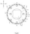
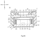
- FIG. 1A to 3B illustrate the detection sensor S1 of the first embodiment.
- Figs. 1A to 2C , 3A , and 3B show a Z-Z' direction (first direction).
- the Z-Z' direction includes a Z direction (one side in the first direction) and a Z' direction (the other side in the first direction).
- Figs. 1A to 2A and 2C to 3B show a Y-Y' direction (second direction).
- the Y-Y' direction is substantially orthogonal to the Z-Z' direction and includes a Y direction (one side in the second direction) and a Y' direction (the other side in the second direction).
- Figs. 1A , 1B , 2B , 2D , 3A , and 3B show an X-X' direction (third direction).
- the X-X' direction is substantially orthogonal to the Z-Z' and Y-Y' directions and includes an X direction (one side in the third direction) and an X' direction (the other side in the third direction).
- the detection sensor S1 includes a sensor unit U (hereinafter also referred to simply as the "unit U").
- the unit U includes a vibratable film 100.
- the vibratable film 100 is constituted by a piezoelectric film exhibiting pyroelectricity.
- the vibratable film 100 includes a film body 110, a first electrode 120, and a second electrode 130.
- the film body 110 is, for example, a resin film, such as a piezoelectric film, having a dimension in the Z-Z' direction (i.e., thickness dimension) of about 40 ⁇ m or about 80 ⁇ m.
- the film body 110 includes a first face on a Z-direction side and a second face on a Z'-direction side.
- the first electrode 120 is provided on the first face of the film body 110.
- the second electrode 130 is provided on the second face of the film body 110. Note that the Z-Z' direction is a thickness direction of the vibratable film 100.
- the vibratable film 100 is configured to be irradiated with infrared rays and thereby generate first electric signals through a pyroelectric effect. Specifically, the vibratable film 100 is spontaneously polarized when not irradiated with infrared rays. When the vibratable film 100 is irradiated with infrared rays resulting in a change in temperature of the vibratable film 100, the spontaneous polarization of the vibratable film 100 accordingly changes to cause a change in voltage of the vibratable film 100, i.e., to generate the first electric signals.
- the vibratable film 100 is further configured to be vibrated by sound waves and thereby generate second electric signals through a piezoelectric effect. Specifically, the vibratable film 100 is configured to vibrate and thereby undergo distortion to accordingly cause a change in voltage, i.e., to generate the second electric signals.
- the unit U further includes a case 200.
- the case 200 accommodates the vibratable film 100.
- the case 200 is constituted by an electrically conductive material (e.g., a metal or the like material).
- the case 200 includes a top plate 210 and a tubular portion 220.
- the top plate 210 is disposed on the Z-direction side relative to the vibratable film 100.
- the top plate 210 includes an opening 211 extending through the top plate 210 in the Z-Z' direction.
- the opening 211 is also disposed on the Z-direction side relative to the vibratable film 100.
- the tubular portion 220 extends in the Z' direction from a perimeter portion of the top plate 210.
- the tubular portion 220 may include a locking portion 221.
- the locking portion 221 is an end portion on the Z'-direction side of the tubular portion 220, and may be bent in a generally L shape or extend in the Z-Z' direction.
- the locking portion 221 can be omitted.
- the tubular portion 220 may be a close-bottomed tube.
- the unit U may further include a circuit board 300.
- the circuit board 300 is fixed to the case 200.
- the circuit board 300 may be fixed to the locking portion 221, which is bent in a generally L shape, of the tubular portion 220 of the case 200 (see Figs. 2A to 2C ), may be fixed by securely inserting the locking portion 221, which extends in the Z-Z' direction, of the tubular portion 220 of the case 200 into an engagement hole of the circuit board 300 (not shown), may be fixed by bonding the locking portion 221 of the tubular portion 220 of the case 200 onto the circuit board 300 with a conductive adhesive or the like (not shown).
- the circuit board 300 may be placed on a bottom of the tubular portion 220 of the case 200.
- the circuit board 300 is disposed on the Z'-direction side relative to, and in spaced relation to, the vibratable film 100.
- the circuit board 300 includes a first face on the Z-direction side and a second face on the Z'-direction side.
- an electrode 310 for external connection.
- the circuit board 300 can be omitted.
- the unit U may further include a field effect transistor 400 (hereinafter also referred to as the FET 400).
- the FET 400 is electrically connected to the vibratable film 100.
- the FET 400 is mounted on the circuit board 300 (see Figs. 2A to 2C ).
- the FET 400 is not shown in Figs. 3A and 3B for convenience of illustration.
- the FET 400 is configured to receive the first electric signals and/or the second electric signals from the vibratable film 100, perform impedance conversion on the first electric signals and/or the second electric signals, and output the converted first electric signals and/or the converted second electric signals as output signals.
- the output signals from the FET 400 are outputted to outside of the detection sensor S1
- the output signals from the FET 400 are may be outputted from the electrode 310 of the circuit board 300 to the outside of the detection sensor S1.
- the FET 400 can also be omitted.
- the FET 400 may be mounted on another circuit board (not shown) outside the detection sensor S1 and electrically connected to the vibratable film 100.
- the unit U may further include a conductive ring 500 and a gate ring 600 of a tubular shape.
- the conductive ring 500 is interposed between a perimeter portion of the vibratable film 100 and the top plate 210 of the case 200, and is in contact with the first electrode 120 of the vibratable film 100.
- the case 200 is constituted by an electrically conductive material.
- the gate ring 600 is electrically conductive, interposed between the perimeter portion of the vibratable film 100 and the circuit board 300, and in contact with the second electrode 130 of the vibratable film 100.
- the first electrode 120 of the vibratable film 100 is electrically connected to the FET 400 via the conductive ring 500, the case 200, and the circuit board 300, and the second electrode 130 of the vibratable film 100 is electrically connected to the FET 400 via the gate ring 600 and the circuit board 300.
- the FET 400 is thus electrically connected to the vibratable film 100.
- the unit U may further include a holder 700 of a tubular shape.
- the holder 700 is constituted by an electrically insulating material.
- the holder 700 is disposed between the gate ring 600 and the tubular portion 220 of the case 200. Accordingly, the holder 700 has an inner shape in a cross section along the X-X' direction that is the same as an outer shape in the cross section along the X-X' direction of the gate ring 600, and the holder 700 has inner dimensions in a cross section along the Y-Y' and X-X' directions that are substantially equal to, or slightly larger than, outer dimensions in the cross section along the Y-Y' and X-X' directions of the gate ring 600.
- the holder 700 has an outer shape in a cross section along the Y-Y' and X-X' directions that is the same as an inner shape in the cross section along the Y-Y' and X-X' directions of the tubular portion 220 of the case 200, and has outer dimensions in a cross section along the Y-Y' and X-X' directions that are substantially equal to, or slightly smaller than, inner dimensions in the cross section along the Y-Y' and X-X' directions of the tubular portion 220 of the case 200.
- the holder 700 may or may not be in contact with a portion of the vibratable film 100 that is located outside a portion of the vibratable film 100 that is contacted by the gate ring 600. Also, the holder 700 may or may not be in contact with the circuit board 300. The holder 700 can be omitted.
- the detection sensor S1 further includes a holder H.
- the holder H includes a holding portion 10 and a front portion 20.
- the holding portion 10 holds the unit U.
- the holding portion 10 is constituted by an insulating material, such as an insulating resin or the like material, and has one of the following configurations (1) to (3).
- the holding portion 10 includes a tubular portion 11 (see Figs. 1A to 3B ).
- the tubular portion 11 includes a thin portion 11a of a tubular shape and a thick portion 11b of a tubular shape.
- the thin portion 11a extends from the front portion 20 in the Z' direction.
- the thick portion 11b extends from the thin portion 11a in the Z' direction.
- the thick portion 11b has a thickness dimension T1 that is larger than a thickness dimension T2 of the thin portion 11a.
- the thick portion 11b of the tubular portion 11 fits over the case 200 of the unit U and holds the unit U. In other words, the case 200 of the unit U fits in the thick portion 11b and is held by the tubular portion 11.
- the thick portion 11b has an inner shape in a cross section along the Y-Y' and X-X' directions that is the same as an outer shape in the cross section along the Y-Y' and X-X' directions of the tubular portion 220 of the case 200, and the thick portion 11b has inner dimensions in a cross section along the Y-Y' and X-X' directions that are substantially equal to, or slightly smaller than, outer dimensions in the cross section along the Y-Y' and X-X' directions of the tubular portion 220 of the case 200.
- a circumferential direction about a central axis of the tubular portion 11 of the holding portion 10 will be hereinafter referred to simply as the "circumferential direction".
- the holding portion 10 includes a tubular portion 11, but the tubular portion 11 does not include the thin portion 11a nor the thick portion 11b (not shown).
- the tubular portion 11 has a substantially uniform thickness dimension from an end on the Z-direction side to an end on the Z'-direction side.
- the tubular portion 11 extends from the front portion 20 in the Z' direction.
- the tubular portion 11 fits over the case 200 of the unit U and holds the unit U. In other words, the case 200 of the unit U fits in the tubular portion 11 and is held by the tubular portion 11.
- the tubular portion 11 has an inner shape in a cross section along the Y-Y' and X-X' directions that is the same as an outer shape in the cross section along the Y-Y' and X-X' directions of the tubular portion 220 of the case 200, and the tubular portion 11 has inner dimensions in a cross section along the Y-Y' and X-X' directions that are substantially equal to, or slightly smaller than, outer dimensions in the cross section along the Y-Y' and X-X' directions of the tubular portion 220 of the case 200.
- the front portion 20 may be, but is not required to be, constituted by an insulating material, such as an insulating resin or the like material, and integrated with the holding portion 10.
- the front portion 20 is disposed on the Z-direction side relative to the case 200 of the unit U.
- the front portion 20 may be disposed on the Z-direction side relative to the case 200 of the unit U with a gap G therebetween and opposed to the case 200.
- the gap G is defined by the front portion 20, the top plate 210 of the case 200, and the thin portion 11a of the holding portion 10.
- the gap G is defined by the front portion 20, the top plate 210 of the case 200, and the tubular portion 11 of the holding portion 10. In any of these cases, the gap G exists between the front portion 20 and the case 200 of the unit U and communicates with the opening 211 of the case 200.
- the holding hole 21 is a through-hole extending in the Z-Z' direction through the front portion 20.
- the holding hole 21 has dimensions that are substantially the same in any cross section along the Y-Y' and X-X' directions from an end on the Z-direction side to an end on the Z'-direction side of the holding hole 21.
- the holder H or the case 200 may further include at least one stop 60.
- the at least one stop 60 may be a single stop 60 or a plurality of stops 60.
- the single stop or plurality of stops 60 are constituted by an insulating material, such as an insulating resin or the like material, and provided at the front portion 20 or the holding portion 10.
- the single stop or plurality of stops 60 are a protrusion or protrusions extending from the front portion 20 in the Z' direction (see Figs. 2A to 2D ).
- the single stop or plurality of stops 60 are a protrusion or protrusions extending from the tubular portion 11 of one of the above-described configurations (1) to (3) of the holding portion 10 toward the central axis of the tubular portion 11.
- the single stop or plurality of stops 60 are disposed on the Z'-direction side relative to the front portion 20.
- the single stop or plurality of stops 60 abut the top plate 210 of the case 200 of the unit U from the Z-direction side. This arrangement allows reserving the gap G between the front portion 20 and the case 200 of the unit U.
- the at least one stop 60 can be omitted.
- the unit U is held by the holding portion 10 in a manner described above and thereby placed in position, which allows reserving the gap G between the front portion 20 and the case 200 of the unit U.
- the holder H further includes a transmissive part 30.
- the transmissive part 30 is configured to transmit at least infrared rays.
- the transmissive part 30 may include an optical filter configured to transmit infrared rays.
- the optical filter may be configured to transmit infrared rays in a predetermined wavelength band.
- the optical filter may be configured to transmit infrared rays in a wavelength band from about 0.7 ⁇ m to about 14 ⁇ m, may be configured to transmit infrared rays and light in a wavelength band or bands near the infrared band (e.g., visible light rays in a wavelength band from about 0.4 ⁇ m to about 0.78 ⁇ m and/or microwaves in a wavelength band from 1 mm to 1 m).
- the optical filter may be constituted by an optical lens made of silicone resin or the like material.
- the optical filter may, but is not limited to, have a thickness dimension (i.e., dimension in the Z-Z' direction) of 0.55 mm ⁇ 0.05 mm and exhibit an average transmittance of 70% or over for light in a wavelength region from 7 ⁇ m to 14 ⁇ m incident at an angle (incident angle) from about 10 degrees to about 20 degrees onto the optical filter.
- a thickness dimension i.e., dimension in the Z-Z' direction
- the optical filter may, but is not limited to, have a thickness dimension (i.e., dimension in the Z-Z' direction) of 0.55 mm ⁇ 0.05 mm and exhibit an average transmittance of 70% or over for light in a wavelength region from 7 ⁇ m to 14 ⁇ m incident at an angle (incident angle) from about 10 degrees to about 20 degrees onto the optical filter.
- the transmissive part 30 may include a transmissive part body 31 and a peripheral portion 32 around the transmissive part body 31.
- the transmissive part body 31 may be constituted by the above-described optical filter, and the peripheral portion 32 may be constituted by a resin molded around the transmissive part body 31.
- the transmissive part body 31 may be constituted by a central portion of the above-described optical filter, and the peripheral portion 32 may be constituted by a peripheral portion of the optical filter.
- the peripheral portion 32 of the latter may or may not be subjected to printing, masking, or the like.
- the transmissive part 30 is provided at the front portion 20 of the holder H.
- the transmissive part 30 is provided at the front portion 20 of the holder H in one of the following manners (6) to (8).
- the transmissive part 30 is securely accommodated in the first hole 21a of the holding hole 21 of the front portion 20.
- the transmissive part 30 has an outer shape in a cross section along the Y-Y' and X-X' directions that is substantially the same as the shape in the cross section along the Y-Y' and X-X' directions of the first hole 21a, and the transmissive part 30 has outer dimensions in a cross section along the Y-Y' and X-X' directions that are substantially equal to, or slightly smaller than, the dimensions in the cross section along the Y-Y' and X-X' directions of the first hole 21a.
- the transmissive part 30 is exposed in the Z direction from the first hole 21a of the front portion 20.
- the transmissive part 30 is exposed in the Z' direction from the second hole 21b of the holding hole 21 of the front portion 20, disposed on the Z-direction side relative to the second hole 21b, the gap G, the opening 211 of the case 200 of the unit U, and the vibratable film 100 of the unit U, and opposed to the vibratable film 100.
- This arrangement allows infrared rays to transmit from the Z-direction side through the transmissive part 30 and be projected onto the vibratable film 100.
- the transmissive part 30 is securely accommodated in the holding hole 21 of the front portion 20.
- the transmissive part 30 has an outer shape in a cross section along the Y-Y' and X-X' directions that is substantially the same as a shape in the cross section along the Y-Y' and X-X' directions of the holding hole 21, and the transmissive part 30 has outer dimensions in a cross section along the Y-Y' and X-X' directions that are substantially equal to, or slightly smaller than, the dimensions in the cross section along the Y-Y' and X-X' directions of the holding hole 21.
- the transmissive part 30 is exposed in the Z and Z' directions from the holding hole 21 of the front portion 20, disposed on the Z-direction side relative to the gap G, the opening 211 of the case 200 of the unit U, and the vibratable film 100 of the unit U, and opposed to the vibratable film 100.
- This arrangement allows infrared rays to transmit from the Z-direction side through the transmissive part 30 and be projected onto the vibratable film 100.
- the transmissive part 30 is embedded in the front portion 20 of the holder H by insert molding or the like means.
- the transmissive part 30 is exposed in the Z and Z' directions from the front portion 20, disposed on the Z-direction side relative to the gap G, the opening 211 of the case 200 of the unit U, and the vibratable film 100 of the unit U, and opposed to the vibratable film 100.
- This arrangement allows infrared rays to transmit from the Z-direction side through the transmissive part 30 and be projected onto the vibratable film 100.
- the holder H further includes at least one sound hole 40 to input therethrough sound waves.
- the at least one sound hole 40 is a single sound hole
- the single sound hole 40 is provided in a portion around the transmissive part 30 of the front portion 20.
- the at least one sound hole 40 is a plurality of sound holes
- the plurality of sound holes 40 are provided in the portion around the transmissive part 30 of the front portion 20 and are arranged in spaced relation along the circumferential direction.
- the single sound hole or plurality of sound holes 40 extend in the Z-Z' direction through the portion around the transmissive part 30 of the front portion 20, are open in both the Z and Z' directions, and communicate with the gap G. As such, the single sound hole or plurality of sound holes 40 can receive input of sound waves from the Z-direction side.
- the single sound hole or plurality of sound holes 40 are opposed to the tubular portion 11 of the holding portion 10 and/or the top plate 210 (a peripheral edge of the opening 211) of the case 200 of the unit U with the gap G existing therebetween, but opposed to neither the opening 211 of the case 200 nor the vibratable film 100 of the unit U.
- the holding portion 10 has the above configuration (2) or (3)
- the single sound hole or plurality of sound holes 40 are opposed to the top plate 210 (the peripheral edge of the opening 211) of the case 200 of the unit U with the gap G existing therebetween, but opposed to neither the opening 211 of the case 200 nor the vibratable film 100 of the unit U. In either case, the vibratable film 100 is not exposed to outside of the holder H through the opening 211, the gap G, or the single sound hole or plurality of sound holes 40 of the case 200.
- the holder H further includes a sound path 50.
- the sound path 50 includes the gap G.
- the gap G exists between the front portion 20 of the holder H and the case 200 of the unit U and forms the sound path, which extends from the single sound hole or plurality of sound holes 40 to the opening 211 of the case 200. Sound waves inputted from the single sound hole or plurality of sound holes 40 pass through the gap G (sound path) and the opening 211 of the case 200 of the unit U and vibrate the vibratable film 100.
- the detection sensor S1 may further include a cover C configured to pass therethrough sound waves.
- the cover C may be constituted by a cloth, or by a waterproof and/or dustproof sheet (not shown).
- the cover C is provided on the portion around the transmissive part 30 of the front portion 20 of the holder H, and covers the sound hole 40 from the Z-direction side.
- the cover C has a ring shape, is provided on the portion around the transmissive part 30 of the front portion 20 of the holder H, and covers the plurality of sound holes 40 from the Z-direction side.
- the cover C can be omitted. Even in this case, as described above, the vibratable film 100 is not exposed to outside of the holder H through the gap G or the single sound hole or plurality of sound holes 40.
- the unit U and the holder H are prepared.
- the front portion 20 is provided with the transmissive part 30 in a manner described above.
- the unit U is fitted into the thick portion 11b of the holding portion 10 of the holder H from the Z'-direction side.
- the holder H is provided with the single stop or plurality of stops 60, the single stop or plurality of stops 60 is brought into abutment with the top plate 210 of the case 200 of the unit U.
- the gap G is defined by the front portion 20 and the tubular portion 11 of the holder H and the top plate 210 of the case 200
- the transmissive part 30 of the holder H is opposed to the vibratable film 100 of the unit U with the gap G and the opening 211 of the top plate 210 of the case 200 existing therebetween
- the single sound hole or plurality of sound holes 40 of the holder H is opposed to the thick portion 11b of the holding portion 10 and/or the top plate 210 (the peripheral edge of the opening 211) of the case 200 with the gap G existing therebetween.
- the unit U is fitted into the thick portion 11b of the holding portion 10 of the holder H from the Z' direction, whereby as described above, the gap G is defined, the transmissive part 30 of the holder H is opposed to the vibratable film 100 of the unit U, and the single sound hole or plurality of sound holes 40 of the holder H is opposed to the thick portion 11b of the holding portion 10 and/or the top plate 210 of the case 200.
- the unit U is thus held in the holding portion 10 of the holder H.
- the unit U is fitted into the tubular portion 11 of the holding portion 10 of the holder H from the Z'-direction side.
- the unit U is held in the holding portion 10 of the holder H, as in the case where the holding portion 10 of the holder H has the above configuration (1) and the single stop or plurality of stops 60 is provided, or alternatively, the case where the holding portion 10 of the holder H has the above configuration (1) and the single stop or plurality of stops 60 is not provided.
- the unit U is made to be held by the plurality of holding arms of the holding portion 10 of the holder H.
- the unit U is held in the holding portion 10 of the holder H, as in the case where the holding portion 10 of the holder H has the above configuration (1) and the single stop or plurality of stops 60 is provided, or alternatively, the case where the holding portion 10 of the holder H has the above configuration (1) and the single stop or plurality of stops 60 is not provided.
- FIG. 4 shows the detection device D according to the first embodiment.
- the detection device D may include the detection sensor S 1 according to one of the above aspects, a low-pass filter F1, and a high-pass filter F2.
- the low-pass filter F1 is electrically connected to the FET 400 to receive output signals from the FET 400.
- the low-pass filter F1 may be provided on a circuit board (not shown), which is electrically connected to the circuit board 300, or on the circuit board 300.
- the low-pass filter F1 is configured to pass signals in a frequency band (first frequency band) out of the received output signals, where the signals in the first frequency band are obtained by impedance converting the first electric signals.
- the low-pass filter F 1 is also configured to attenuate signals in a frequency band higher than the frequency band of the signals capable of passing through the low-pass filter (attenuate signals in a frequency band higher than the first frequency band).
- signals obtained by impedance converting the first electric signals fall within a frequency band of 0.35 Hz to 5.0 Hz, and accordingly the low-pass filter F1 is configured to pass, out of the received output signal, signals in a frequency band of 10 Hz and lower and to attenuate signals in a frequency band of higher than 10 Hz (not including 10 Hz).
- the high-pass filter F2 is electrically connected to the FET 400 to receive output signals from the FET 400.
- the high-pass filter F2 may be provided on the circuit board (not shown), which is electrically connected to the circuit board 300, or on the circuit board 300.
- the high-pass filter F2 is configured to pass, out of the received output signals, signals in a frequency band (second frequency band) higher than the frequency band of the signals capable of passing through the low-pass filter F 1 (higher than the first frequency band).
- the high-pass filter F2 is also configured to attenuate signals in a frequency band lower than the frequency band of the signals capable of passing through the high-pass filter F2 (attenuate signals in a frequency band higher than the second frequency band).
- the high-pass filter F2 is configured to pass signals in a frequency band of 200 Hz to 300 Hz and to attenuate signals in a frequency band of 200 Hz and lower.
- the detection device D may further include a controller CE.
- the controller CE may be provided on the circuit board (not shown) electrically connected to the circuit board 300, or on the circuit board 300.
- the controller CE is electrically connected to the low-pass filter F1 and to the high-pass filter F2 individually.
- the controller CE is configured to receive signals that have passed through the low-pass filter F1 and configured to receive signals that have passed through the high-pass filter F2.
- the controller CE may be, but is not required to be, electrically connected to the FET 400 to receive output signals from the FET 400.
- the controller CE may be configured to determine whether or not the controller CE has received signals only from the low-pass filter F1.
- the controller CE determines whether or not it has received signals from the low-pass filter F1 (first determination). If the controller CE determines that it has received signals from the low-pass filter F1, then the controller CE counts for a predetermined period, using a timer circuit or a software timer on an internal memory in the controller CE, and determines whether or not it has received signals from the high-pass filter F2 within the predetermined period (second determination).
- the controller CE determines that it has received signals from the high-pass filter F2 within the predetermined period (that is, if the controller CE determines that it has received signals not only from the low-pass filter F1), then the controller CE returns to the processing of the first determination. On the other hand, if the controller CE determines that it has not received any signals from the high-pass filter F2 within the predetermined period, the controller CE determines that it has received signals only from the low-pass filter F1.
- the controller CE is configured to perform the second determination within the predetermined period after performing the first determination. Instead, the controller CE may be configured to perform the first determination within the predetermined period after performing the second determination.
- the controller CE determines that it has received signals only from the low-pass filter F1
- this determination means that the controller CE has only received signals obtained by impedance converting the first electric signals from the vibratable film 100 that have been generated by irradiating the vibratable film 100 with infrared rays
- the controller CE determines that the infrared rays have been applied to the vibratable film 100. This is how the controller CE is able to detect infrared rays.
- the controller CE determines that it has received signals not only from the low-pass filter F1
- this determination means that the controller CE has received signals obtained by impedance converting the second electric signals from the vibratable film 100 that have been generated by vibration of the vibratable film 100 due to sound waves
- the controller CE determines that the vibratable film 100 has been vibrated by sound waves. This is how the controller CE is able to detect sound waves.
- the controller CE may be further configured such that if the controller CE determines that it has received signals only from the low-pass filter F1, the controller CE performs signal processing, such as voice recognition processing, on signals received from the FET 400, or alternatively on signals received from the low-pass filter F1 and on signals received from the high-pass filter F2.
- the controller CE may also be configured to amplify signals received from the FET 400, or alternatively signals received from the low-pass filter F1 and signals received from the high-pass filter F2, and perform the above-described signal processing on the amplified signals.
- the controller CE may be configured to return to the first determination on the basis of externally provided instruction information.
- the controller CE may be configured such that if it determines that it has received signals only from the low-pass filter F1, the controller CE counts for a predetermined period, using the timer circuit or the software timer on the internal memory in the controller CE, and perform signal processing within the predetermined period in one of the above manners.
- the controller CE may be configured to return to the processing of the first determination after the predetermined period has elapsed.
- the controller CE may not include the configuration for performing the above signal processing and may be configured to repeat the processing of the first determination and the processing of the second determination in this order or in the reverse order.
- the detection device D can detect an approach of the human body (including placing a hand over the detection sensor S1) in a manner described above.
- the detection device D is incorporated in a waste container, for example, the detection device D can detect the approach of the human body on the basis of infrared irradiation onto the vibratable film 100 as described above and may be configured to perform voice recognition processing on a voice inputted to the detection sensor S1.
- the waste container may be configured to open and close a lid thereof in response to either detection of an approach of a human or detection of a voice.
- the detection device D is incorporated in furniture, an electrical appliance, or the like, as in a waste container, the furniture, the electrical appliance, or the like can be operated by either detecting an approach of a human or detecting a sound.
- the detection device D is incorporated in a vending machine or a ticket machine, for example, the detection device D may be configured to detect an approach of a human body on the basis of infrared irradiation onto the vibratable film 100 and then perform voice recognition processing on a voice inputted to the detection sensor S1 as described above.
- the vending machine or the ticket machine may allow the human to purchase a product by his or her voice without touching the vending machine or the ticket machine with the human body.
- the detection device D is incorporated in a fire detector, for example, the detection device D may be configured to detect a temperature change caused by a fire or other event on the basis of infrared irradiation onto the vibratable film 100 and then perform voice recognition processing on a voice inputted to the detection sensor S1 as described above.
- the fire detector can transmit processed voice data through the Internet or other lines.
- the fire detector may be configured to turn on an alarm buzzer or the like in response to the detection of the temperature change caused by the fire or other event.
- the detection device D is incorporated in an alarm device, such as a security camera
- the detection device D may be configured to detect an approach of a human body on the basis of infrared irradiation onto the vibratable film 100 and then perform voice recognition processing as described above.
- the alarm device may record processed voice data (voices, sounds, or the like) and/or transmit the processed voice data through the Internet or other lines.
- the detection sensor S1 described above provides at least the following technical features and effects (1) to (5).
- the detection sensor S1 can receive input of infrared rays and input of sound waves from the same direction (Z direction) for the following reasons.
- the front portion 20 of the holder H is disposed on the Z-direction side relative to the case 200 of the unit U.
- the transmissive part 30 of the holder H is provided at the front portion 20, exposed from the front portion 20 in the Z and Z' directions, and opposed to the vibratable film 100 with the opening 211 of the case 200 interposed therebetween.
- the detection sensor S1 allows at least infrared rays to transmit from the Z-direction side through the transmissive part 30 of the holder H and be projected onto the vibratable film 100.
- the at least one sound hole 40 is provided in the portion around the transmissive part 30 of the front portion 20 of the holder H, is open in the Z direction, and communicates with the gap G.
- the gap G communicates with the opening 211 of the case 200.
- the detection sensor S1 also allows sound waves to enter into the at least one sound hole 40 from the Z-direction side, to pass through the at least one sound hole 40, the gap G, and the opening 211, and to vibrate the vibratable film 100.
- the vibratable film 100 is not exposed to outside of the detection sensor S1 for the following reasons.
- the transmissive part 30 of the holder H is provided at the front portion 20 and opposed to the vibratable film 100 with the opening 211 of the case 200 interposed therebetween.
- the at least one sound hole 40 is provided in the portion around the transmissive part 30 of the front portion 20 of the holder H. Accordingly, the vibratable film 100 is not exposed to outside of the detection sensor S1 through the at least one sound hole 40, the sound path 50 (gap G), or the opening 211.
- the unit U is configured to be held by the holding portion 10 of the holder H, making it possible to set a desired holding position of the holding portion 10 relative to the unit U.
- Changing the holding position of the holding portion 10 relative to the unit U changes a linear distance in the Z-Z' direction between the transmissive part 30 of the holder H and the vibratable film 100 of the unit U held by the holding portion 10 of the holder H, making it possible to change the sensitivity of the detection sensor S1 to infrared rays.
- the incident angle herein means an angle which a line perpendicular to the surface of the vibratable film 100 of the detection sensor S1 (i.e., (the normal to this surface) forms with infrared rays incident on the vibratable film 100 of the detection sensor S1.
- the detection sensor S1 has improved versatility for the following reasons. Since the detection sensor S1 is configured such that the vibratable film 100 thereof is not exposed to outside of the detection sensor S1 as described above, the detection sensor S1 can be installed in a place laden with dirt or dust and/or a place where water may adhere to.
- the detection device D includes the detection sensor S1
- the detection device D also provides the above technical features and effects (1) to (5).
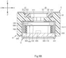
- FIG. 5A to 5C illustrate the detection sensor S2 of the second embodiment.
- the detection sensor S2 is configured similarly to the detection sensor S1 described above except for the following differences: the front portion 20 of the holder H of the detection sensor S2 directly abuts the top plate 210 of the case 200 of the unit U, and the at least one sound hole 40 and the sound path 50 of the holder H are different in configuration from the at least one sound hole 40 and the sound path 50 of the holder H of the detection sensor S1.
- the detection sensor S2 will be described focusing on these differences and omitting overlapping descriptions.
- FIG. 5A show the Z-Z' and Y-Y' directions similarly to those in Fig. 2A .
- Fig. 5B shows the Z-Z' and X-X' directions similarly to those in Fig. 2B .
- Fig. 5C shows the Y-Y' and X-X' directions similarly to those in Fig. 2D .
- the holding portion 10 of the holder H can have any one of the above configurations (1) to (3).
- the holding portion 10 of the holder H has the above configuration (2).
- the front portion 20 of the holder H of the detection sensor S2 directly abuts the top plate 210 of the case 200 of the unit U.
- the gap G is not provided between the front portion 20 of the holder H and the top plate 210 of the case 200, nor the detection sensor S2 is provided with the at least one stop 60.
- the second hole 21b of the holding hole 21 of the front portion 20 extends from the first hole 21a to the opening 211 of the case 200 of the unit U (see Figs. 5A to 5C ).
- the transmissive part 30 is exposed in the Z direction from the first hole 21a of the holding hole 21 of the front portion 20.
- the transmissive part 30 is exposed in the Z' direction from the second hole 21b of the holding hole 21 of the front portion 20, disposed on the Z-direction side relative to the second hole 21b, the opening 211 of the case 200 of the unit U, and the vibratable film 100 of the unit U, and opposed to the vibratable film 100.
- This arrangement allows infrared rays to transmit from the Z-direction side through the transmissive part 30 and be projected onto the vibratable film 100.
- the front portion 20 is provided with the holding hole 21 and the holding hole 21 has the above configuration (5), (10) the front portion 20 is provided a hole (not shown) in a portion on the Z'-direction side relative to the holding hole 21, and the hole extends from the holding hole 21 to the opening 211 of the case 200 of the unit U.
- the transmissive part 30 is exposed in the Z direction from the holding hole 21 of the front portion 20, exposed in the Z' direction from the hole of the front portion 20, and disposed on the Z-direction side relative to the hole, the opening 211 of the case 200 of the unit U, and the vibratable film 100 of the unit U, and opposed to the vibratable film 100.
- This arrangement allows infrared rays to transmit from the Z-direction side through the transmissive part 30 and be projected onto the vibratable film 100.
- the front portion 20 is not provided with the holding hole 21, (11) the front portion 20 is provided with a hole (not shown) extending from the transmissive part 30 to the opening 211 of the case 200 of the unit U.
- the transmissive part 30 is exposed in the Z direction from the front portion 20, exposed in the Z' direction from the hole of the front portion 20, disposed on the Z-direction side relative to the hole, the opening 211 of the case 200 of the unit U, and the vibratable film 100 of the unit U, and opposed to the vibratable film 100.
- This arrangement allows infrared rays to transmit from the Z-direction side through the transmissive part 30 and be projected onto the vibratable film 100.
- the at least one sound hole 40 and the sound path 50 of the holder H of the detection sensor S2 are provided in a portion around the transmissive part 30 of the front portion 20.
- the single sound hole or plurality of sound holes 40 of the holder H of the detection sensor S2 have substantially the same configurations as the single sound hole or plurality of sound holes 40 of the holder H of the detection sensor S1, except that the hole or holes do not extend in the Z-Z' direction through the portion around the transmissive part 30 of the front portion 20.
- the single sound hole or plurality of sound holes 40 of the holder H of the detection sensor S2 are open to the Z-direction side and can receive input of sound waves from the Z-direction side.
- the sound path 50 of the holder H of the detection sensor S2 extends from the single sound hole or plurality of sound holes 40 to the opening 211 of the case 200 and communicates with the single sound hole or plurality of sound holes 40 and the opening 211.
- the sound path 50 may include a single recess or a plurality of recesses 51 and one of the second hole 21b of the above configuration (9), the hole of the above configuration (10), or the hole of the above configuration (11).
- the sound path 50 may include a single lateral hole or a plurality of lateral holes (not shown) and one of the second hole 21b of the above configuration (9), the hole of the above configuration (10), or the hole of the above configuration (11).
- the or each recess 51 extends from the or a corresponding sound hole 40 to one of the second hole 21b of the above configuration (9), the hole of the above configuration (10), or the hole of the above configuration (11), also extends in the Z' direction from the sound hole 40 or the corresponding sound hole 40, and is open in the Z' direction.
- the or each lateral holes extends from the or a corresponding sound hole 40 to one of the second hole 21b of the above configuration (9), the hole of the above configuration (10), or the hole of the above configuration (11). Sound waves inputted from the single sound hole or plurality of sound holes 40 pass through the sound path 50 of the front portion 20 and the opening 211 of the case 200 of the unit U and vibrate the vibratable film 100.
- the single sound hole or plurality of sound holes 40 are opposed to the tubular portion 11 of the holding portion 10 and/or the top plate 210 of the case 200 of the unit U with the single recess or plurality of recesses 51 of the sound path 50 existing therebetween, but opposed to neither the opening 211 of the case 200 nor the vibratable film 100 of the unit U with the single recess or plurality of recesses 51 of the sound path 50 existing therebetween.
- the single sound hole or plurality of sound holes 40 are opposed to the top plate 210 of the case 200 of the unit U with the single recess or plurality of recesses 51 of the sound path 50 existing therebetween, but opposed to neither the opening 211 of the case 200 nor the vibratable film 100 of the unit U with the single recess or plurality of recesses 51 of the sound path 50 existing therebetween. In either case, the vibratable film 100 is not exposed to outside of the holder H through the opening 211 of the case 200, the sound path 50, or the single sound hole or plurality of sound holes 40.
- the or each sound hole 40 is opposed to a bottom of the or a corresponding lateral hole of the sound path 50, and thus opposed to neither the opening 211 of the case 200 nor the vibratable film 100 of the unit U.
- the detection device D of the second embodiment has the same configuration as the detection device D of the first embodiment, except that the detection device D of the second embodiment includes the detection sensor S2 of an aspect described above in place of the detection sensor S1 of an aspect described above.
- the detection sensor S2 described above provides at least the following technical features and effects (1) and (2).
- the detection sensor S2 can receive input of infrared rays and input of sound waves from the same direction (Z direction) for the following reasons.
- the front portion 20 of the holder H is disposed on the Z-direction side relative to the case 200 of the unit U.
- the transmissive part 30 of the holder H is provided at the front portion 20, exposed from the front portion 20 in the Z and Z' directions, and opposed to the vibratable film 100 with the opening 211 of the case 200 interposed therebetween.
- the detection sensor S2 allows at least infrared rays to transmit from the Z-direction side through the transmissive part 30 of the holder H and be projected onto the vibratable film 100.
- the at least one sound hole 40 is provided in the portion around the transmissive part 30 of the front portion 20 of the holder H and is open in the Z direction.
- the sound path 50 is provided in the front portion 20 and extends from the at least one sound hole 40 to the opening 211 of the case 200.
- the detection sensor S2 also allows sound waves to enter into the at least one sound hole 40 from the Z-direction side, to pass through the at least one sound hole 40, the sound path 50, and the opening 211, and to vibrate the vibratable film 100.
- the vibratable film 100 is not exposed to outside of the detection sensor S2 for the following reasons.
- the transmissive part 30 of the holder H is provided at the front portion 20 and opposed to the vibratable film 100 with the opening 211 of the case 200 interposed therebetween.
- the at least one sound hole 40 is provided in the portion around the transmissive part 30 of the front portion 20 of the holder H. Accordingly, the vibratable film 100 is not exposed to outside of the detection sensor S2 through the at least one sound hole 40, the sound path 50, or the opening 211.
- the cover C blocks the at least one sound hole 40, further reducing the possibility that the dirt, etc. enters the detection sensor S2 through the at least one sound hole 40 and the sound path 50 and adheres to the vibratable film 100.
- the detection sensor S2 also provides technical features and effects similar to the technical features and effects (3) to (5) of the detection sensor S1.
- the detection device D of the second embodiment which includes the detection sensor S2, also provides technical features and effects similar to those of the detection sensor S2.
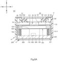
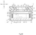
- FIG. 6A to 6C illustrate the detection sensor S3 of the third embodiment.
- the detection sensor S3 is configured similarly to the detection sensor S1 described above except for the following differences: the holder H further includes a spacer SP interposed between the front portion 20 and the top plate 210 of the case 200, and the at least one sound hole 40 and the sound path 50 of the holder H are different in configuration from the at least one sound hole 40 and the sound path 50 of the holder H of the detection sensor S1.
- the detection sensor S3 will be described focusing on these differences and omitting overlapping descriptions.
- FIG. 6A show the Z-Z' and Y-Y' directions similarly to those in Fig. 2A .
- Fig. 6B shows the Z-Z' and X-X' directions similarly to those in Fig. 2B .
- Fig. 6C shows the Y-Y' and X-X' directions similarly to those in Fig. 2D .
- the spacer SP provided separately from the holding portion 10 and the front portion 20 of the holder H, has a generally ring-shape in a cross section along the Y-Y' and X-X' directions and is constituted by an insulating material, such as an insulating resin or the like material.
- the spacer SP is provided with a central hole 52 extending in the Z-Z' direction through the spacer SP and being located between the transmissive part 30 and the opening 211 of the case 200 of the unit U.
- the spacer SP is disposed inside the tubular portion 11 of the holding portion 10 having one of the above configurations (1) to (3), and is interposed between the front portion 20 of the holder H and the top plate 210 of the case 200 of the unit U.
- the spacer SP abuts the front portion 20 of the holder H from the Z'-direction side and abuts the top plate 210 of the case 200 from the Z direction.
- the front portion 20 of the holder H indirectly abuts the top plate 210 of the case 200 via the spacer SP.
- the gap G is not provided between the front portion 20 of the holder H and the top plate 210 of the case 200, nor the detection sensor S3 is provided with the at least one stop 60.
- Figs. 6A to 6C illustrate the holding portion 10 of the holder H of the above configuration (2).
- the sound path 50 of the holder H of the detection sensor S2 may be provided (a) in the spacer SP, or alternatively (b) in both the front portion 20 and the spacer SP.
- the detection sensor S3 further has one of the following configurations.
- the transmissive part 30 has the above configuration (6)
- the central hole 52 of the spacer SP extends from the second hole 21b of the holding hole 21 of the front portion 20 to the opening 211 of the top plate 210 of the case 200 and communicates with the second hole 21b and the opening 211.
- the transmissive part 30 is disposed on the Z-direction side relative to the second hole 21b, the central hole 52 of the spacer SP, the opening 211 of the case 200 of the unit U, and the vibratable film 100 of the unit U, and opposed to the vibratable film 100.
- the transmissive part 30 has the above configuration (7)
- the central hole 52 of the spacer SP extends from the holding hole 21 of the front portion 20 to the opening 211 of the top plate 210 of the case 200 and communicates with the holding hole 21 and the opening 211.
- the transmissive part 30 is disposed on the Z-direction side relative to the central hole 52 of the spacer SP, the opening 211 of the case 200 of the unit U, and the vibratable film 100 of the unit U, and opposed to the vibratable film 100.
- the transmissive part 30 has the above configuration (8)
- the central hole 52 of the spacer SP extends from the transmissive part 30 to the opening 211 of the top plate 210 of the case 200 and communicates with the opening 211.
- the transmissive part 30 is disposed on the Z-direction side relative to the central hole 52 of the spacer SP, the opening 211 of the case 200 of the unit U, and the vibratable film 100 of the unit U, and opposed to the vibratable film 100.
- the single sound hole or plurality of sound holes 40 of the holder H of the detection sensor S3 have substantially the same configuration as those of the detection sensor S1 and are provided in the portion around the transmissive part 30 of the front portion 20.
- the sound path 50 of the holder H of the detection sensor S3 extends from the single sound hole or plurality of sound holes 40 to the opening 211 of the case 200, and communicates with the single sound hole or plurality of sound holes 40 and the opening 211.
- the sound path 50 may include a single peripheral hole or a plurality of peripheral holes 53, and the central hole 52 (see Figs. 6A to 6C ), or include a single lateral hole or a plurality of lateral holes (not shown), and the central hole 52.
- the or each peripheral holes 53 extends in the Z-Z' direction through a portion around the central hole 52 of the spacer SP and extends from the or a corresponding sound hole 40 to the central hole 52.
- the or each lateral hole is provided in the portion around the central hole 52 of the spacer SP, and extends from the or a corresponding sound hole 40 to the central hole 52. Sound waves inputted from the single sound hole or plurality of sound holes 40 pass through the sound path 50 and the opening 211 of the case 200 of the unit U, and vibrate the vibratable film 100.
- the single sound hole or plurality of sound holes 40 are opposed to the tubular portion 11 of the holding portion 10 and/or the top plate 210 of the case 200 of the unit U with the single peripheral hole or plurality of peripheral holes 53 existing therebetween, but opposed to neither the opening 211 of the case 200 nor the vibratable film 100 of the unit U.
- the single sound hole or plurality of sound holes 40 are opposed to the top plate 210 of the case 200 of the unit U with the single peripheral hole or plurality of peripheral holes 53 existing therebetween, but opposed to neither the opening 211 of the case 200 nor the vibratable film 100 of the unit U. In any of these cases, the vibratable film 100 is not exposed to outside of the holder H through the opening 211 of the case 200, the sound path 50, or the single sound hole or plurality of sound holes 40.
- the or each of sound hole 40 is opposed to a bottom of the or a corresponding lateral hole of the spacer SP, and thus opposed to neither the opening 211 of the case 200 nor the vibratable film 100of the unit U.
- the detection sensor S3 further has one of the following configurations.
- the second hole 21b of the holding hole 21 of the front portion 20 extends from the first hole 21a to the central hole 52 of the spacer SP, and the central hole 52 of the spacer SP extends from the second hole 21b to the opening 211 of the case 200 of the unit U.
- the transmissive part 30 is exposed in the Z direction from the first hole 21a of the holding hole 21 of the front portion 20.
- the transmissive part 30 is exposed in the Z' direction from the second hole 21b of the holding hole 21 of the front portion 20, disposed on the Z-direction side relative to the second hole 21b, the central hole 52, the opening 211 of the case 200 of the unit U, and the vibratable film 100 of the unit U, and opposed to the vibratable film 100.
- This arrangement allows infrared rays to transmit from the Z-direction side through the transmissive part 30 and be projected onto the vibratable film 100.
- the front portion 20 is provided with the holding hole 21 and the holding hole 21 has the above configuration (5), (13) the front portion 20 is provided a hole (not shown) in a portion on the Z'-direction side relative to the holding hole 21, the hole extends from the holding hole 21 to the central hole 52 of the spacer SP, and the central hole 52 of the spacer SP extends from the hole to the opening 211 of the case 200 of the unit U.
- the front portion 20 is not provided with the holding hole 21, (14) the front portion 20 is provided with a hole (not shown) extending from the transmissive part 30 to the central hole 52 of the spacer SP, and the central hole 52 of the spacer SP extends from the hole to the opening 211 of the case 200 of the unit U.
- the transmissive part 30 is exposed in the Z direction from the front portion 20, exposed in the Z' direction from the hole of the front portion 20, disposed on the Z-direction side relative to the hole, the central hole 52, the opening 211 of the case 200 of the unit U, and the vibratable film 100 of the unit U, and opposed to the vibratable film 100.
- This arrangement allows infrared rays to transmit from the Z-direction side through the transmissive part 30 and be projected onto the vibratable film 100.
- the single sound hole or plurality of sound holes 40 of the holder H of the detection sensor S3 have substantially the same configuration as those of the detection sensor S2 and are provided in the portion around the transmissive part 30 of the front portion 20.
- the sound path 50 of the holder H of the detection sensor S3 extends from the single sound hole or plurality of sound holes 40 to the opening 211 of the case 200 and communicates with the single sound hole or plurality of sound holes 40 and the opening 211.
- the sound path 50 may include a single recess or a plurality of recesses 51 of the front portion 20, one of the second hole 21b of the above configuration (12), the hole of the above configuration (13), or the hole of the above configuration (14) of the front portion 20, and the central hole 52 of the spacer SP.
- the sound path 50 may include a single lateral hole or a plurality of lateral holes (not shown) of the front portion 20, one of the second hole 21b of the above configuration (12), the hole of the above configuration (13), or the hole of the above configuration (14) of the front portion 20, and the central hole 52 of the spacer SP.
- the or each of recess 51 is provided in the front portion 20, extends from the or a corresponding sound hole 40 to one of the second hole 21b of the above configuration (12), the hole of the above configuration (13), or the hole of the above configuration (14), also extends in the Z' direction from the sound hole 40 or the corresponding sound hole 40, and is open in the Z' direction.
- the or each lateral hole is provided in the front portion 20, extends from the or a corresponding sound hole 40 to one of the second hole 21b of the above configuration (12), the hole of the above configuration (13), or the hole of the above configuration (14).
- the central hole 52 of the spacer SP extends from one of the second hole 21b of the above configuration (12), the hole of the above configuration (13), or the hole of the above configuration (14) to the opening 211 of the case 200 of the unit U.
- Sound waves inputted from the single sound hole or plurality of sound holes 40 pass through the sound path 50 of the front portion 20 and the opening 211 of the case 200 of the unit U and vibrate the vibratable film 100.
- the single sound hole or plurality of sound holes 40 are opposed to the spacer SP with the single recess or plurality of recesses 51 of the front portion 20 existing therebetween, but opposed to neither the opening 211 of the case 200 nor the vibratable film 100 of the unit U.
- the sound path 50 includes the single lateral hole or plurality of lateral holes of the front portion 20, the or each sound hole 40 is opposed to a bottom of the or a corresponding lateral hole of the front portion 20, and thus opposed to neither the opening 211 of the case 200 nor the vibratable film 100 of the unit U. In either case, the vibratable film 100 is not exposed to outside of the holder H through the opening 211 of the case 200, the sound path 50, or the single sound hole or plurality of sound holes 40.
- the detection device D of the third embodiment has the same configuration as the detection device D of the first embodiment, except that the detection device D of the third embodiment includes the detection sensor S3 of an aspect described above in place of the detection sensor S1 of an aspect described above.
- the detection sensor S3 described above provides at least the following technical features and effects (1) and (2).
- the detection sensor S3 can receive input of infrared rays and input of sound waves from the same direction for the following reasons.
- the front portion 20 of the holder H is disposed on the Z-direction side relative to the case 200 of the unit U.
- the transmissive part 30 of the holder H is provided at the front portion 20, exposed from the front portion 20 in the Z and Z' directions, and opposed to the vibratable film 100 with the central hole 52 of the spacer SP and the opening 211 of the case 200 interposed therebetween.
- the detection sensor S3 allows at least infrared rays to transmit from the Z-direction side through the transmissive part 30 of the holder H and be projected onto the vibratable film 100.
- the at least one sound hole 40 is provided in the portion around the transmissive part 30 of the front portion 20 of the holder H and is open in the Z direction.
- the sound path 50 is provided in the spacer SP or in the front portion 20 and the spacer SP, and extends from the at least one sound hole 40 to the opening 211 of the case 200.
- the detection sensor S3 also allows sound waves to enter into the at least one sound hole 40 from the Z-direction side, to pass through the at least one sound hole 40, the sound path 50, and the opening 211, and to vibrate the vibratable film 100.
- the vibratable film 100 is not exposed to outside of the detection sensor S3 for the following reasons.
- the transmissive part 30 of the holder H is provided at the front portion 20 and opposed to the vibratable film 100 with the opening 211 of the case 200 interposed therebetween.
- the at least one sound hole 40 is provided in the portion around the transmissive part 30 of the front portion 20 of the holder H. Accordingly, the vibratable film 100 is not exposed to outside of the detection sensor S3 through the at least one sound hole 40, the sound path 50, or the opening 211.
- the cover C blocks the at least one sound hole 40, further reducing the possibility that the dirt, etc. enters the detection sensor S3 through the at least one sound hole 40 and the sound path 50 and adheres to the vibratable film 100.
- the detection sensor S3 also provides technical features and effects similar to the technical features and effects (3) to (5) of the detection sensor S1.
- the detection device D of the second embodiment which includes the detection sensor S3, also provides technical features and effects similar to those of the detection sensor S3.
- the holding portion 10 of the holder H can be modified in any manner as long as it is configured to hold the unit U of any of the above aspects on the Z'-direction side relative to the front portion 20 of any of the above aspects.
- the at least one sound hole 40 of the holder H can be modified in any manner as long as it is provided in the portion around the transmissive part 30 of the front portion 20 and is open in the Z direction.
- the sound path 50 of the holder H can be modified in any manner as long as it extends from the at least one sound hole 40 to the opening 211 of the case 200 of the unit U.
Landscapes
- Physics & Mathematics (AREA)
- General Physics & Mathematics (AREA)
- Engineering & Computer Science (AREA)
- Acoustics & Sound (AREA)
- Signal Processing (AREA)
- Spectroscopy & Molecular Physics (AREA)
- Power Engineering (AREA)
- Photometry And Measurement Of Optical Pulse Characteristics (AREA)
- Piezo-Electric Transducers For Audible Bands (AREA)
- Details Of Audible-Bandwidth Transducers (AREA)
Applications Claiming Priority (1)
| Application Number | Priority Date | Filing Date | Title |
|---|---|---|---|
| JP2023145364A JP2025038633A (ja) | 2023-09-07 | 2023-09-07 | 検知センサ |
Publications (2)
| Publication Number | Publication Date |
|---|---|
| EP4521080A1 true EP4521080A1 (de) | 2025-03-12 |
| EP4521080B1 EP4521080B1 (de) | 2025-10-15 |
Family
ID=92456591
Family Applications (1)
| Application Number | Title | Priority Date | Filing Date |
|---|---|---|---|
| EP24194738.1A Active EP4521080B1 (de) | 2023-09-07 | 2024-08-15 | Detektionssensor |
Country Status (6)
| Country | Link |
|---|---|
| US (1) | US20250085167A1 (de) |
| EP (1) | EP4521080B1 (de) |
| JP (1) | JP2025038633A (de) |
| KR (1) | KR20250036689A (de) |
| CN (1) | CN119573778A (de) |
| TW (1) | TW202511709A (de) |
Citations (5)
| Publication number | Priority date | Publication date | Assignee | Title |
|---|---|---|---|---|
| JPS5446525U (de) | 1977-09-07 | 1979-03-31 | ||
| JPS5648189U (de) * | 1979-09-20 | 1981-04-28 | ||
| WO2011159003A1 (ko) * | 2010-06-17 | 2011-12-22 | 주식회사 비에스이 | 마이크로폰 |
| JP2020148018A (ja) | 2019-03-14 | 2020-09-17 | 公益財団法人鉄道総合技術研究所 | 地盤振動予測方法 |
| US20220065691A1 (en) * | 2020-09-03 | 2022-03-03 | Hosiden Corporation | Detection sensor and detection device including the same |
-
2023
- 2023-09-07 JP JP2023145364A patent/JP2025038633A/ja active Pending
-
2024
- 2024-06-21 TW TW113123164A patent/TW202511709A/zh unknown
- 2024-08-09 US US18/799,011 patent/US20250085167A1/en active Pending
- 2024-08-15 EP EP24194738.1A patent/EP4521080B1/de active Active
- 2024-08-30 KR KR1020240117437A patent/KR20250036689A/ko active Pending
- 2024-09-04 CN CN202411233510.3A patent/CN119573778A/zh active Pending
Patent Citations (6)
| Publication number | Priority date | Publication date | Assignee | Title |
|---|---|---|---|---|
| JPS5446525U (de) | 1977-09-07 | 1979-03-31 | ||
| JPS5648189U (de) * | 1979-09-20 | 1981-04-28 | ||
| WO2011159003A1 (ko) * | 2010-06-17 | 2011-12-22 | 주식회사 비에스이 | 마이크로폰 |
| JP2020148018A (ja) | 2019-03-14 | 2020-09-17 | 公益財団法人鉄道総合技術研究所 | 地盤振動予測方法 |
| US20220065691A1 (en) * | 2020-09-03 | 2022-03-03 | Hosiden Corporation | Detection sensor and detection device including the same |
| JP2022042578A (ja) | 2020-09-03 | 2022-03-15 | ホシデン株式会社 | 検知センサ及びこれを備えた検知装置 |
Also Published As
| Publication number | Publication date |
|---|---|
| CN119573778A (zh) | 2025-03-07 |
| KR20250036689A (ko) | 2025-03-14 |
| JP2025038633A (ja) | 2025-03-19 |
| TW202511709A (zh) | 2025-03-16 |
| EP4521080B1 (de) | 2025-10-15 |
| US20250085167A1 (en) | 2025-03-13 |
Similar Documents
| Publication | Publication Date | Title |
|---|---|---|
| EP0146933B1 (de) | Schallerzeugendes Gerät | |
| EP1836477B1 (de) | Unterdrückung des hintergrundsignals bei einem fotoakustischen detektor | |
| US6528778B1 (en) | Optical sensor and optical unit | |
| EP3964808B1 (de) | Detektionssensor und diesen enthaltende detektionsvorrichtung | |
| CN113811747A (zh) | 光学麦克风组合件 | |
| EP4521080B1 (de) | Detektionssensor | |
| JP2009060380A (ja) | カメラモジュール | |
| WO2011108441A1 (ja) | 圧電スピーカおよびこの圧電スピーカを用いた警報装置 | |
| TWI781594B (zh) | 觸控顯示模組及其螢幕下指紋辨識模組 | |
| JP2020134235A (ja) | 光学装置 | |
| JP2000199890A (ja) | 液晶表示装置およびその実装方法 | |
| US6906807B2 (en) | Membrane type optical transducers particularly useful as optical microphones | |
| JP2948102B2 (ja) | 圧電形加速度ピックアップ | |
| JP2757859B2 (ja) | 携帯端末機 | |
| US4434549A (en) | Method of making an improved pyroelectric sensor | |
| JPH0230740Y2 (de) | ||
| JPH11185179A (ja) | 熱煙複合型火災感知器及びその製造方法 | |
| WO2025220611A1 (ja) | 電子聴診装置及びダイヤフラム変位検出装置 | |
| JP2002048960A (ja) | 光学素子固定機構 | |
| JP2003348401A (ja) | カメラ及びこれに用いる撮像素子ユニット | |
| JP2025162504A (ja) | 電子聴診装置及びダイヤフラム変位検出装置 | |
| JPH05153694A (ja) | 開放型超音波マイクロホン | |
| JPH02240529A (ja) | 炎検出装置 | |
| JPH0526726A (ja) | 赤外線検出器 | |
| JP2004347390A (ja) | 合わせ硝子の破壊検出用センサー装置 |
Legal Events
| Date | Code | Title | Description |
|---|---|---|---|
| PUAI | Public reference made under article 153(3) epc to a published international application that has entered the european phase |
Free format text: ORIGINAL CODE: 0009012 |
|
| STAA | Information on the status of an ep patent application or granted ep patent |
Free format text: STATUS: THE APPLICATION HAS BEEN PUBLISHED |
|
| AK | Designated contracting states |
Kind code of ref document: A1 Designated state(s): AL AT BE BG CH CY CZ DE DK EE ES FI FR GB GR HR HU IE IS IT LI LT LU LV MC ME MK MT NL NO PL PT RO RS SE SI SK SM TR |
|
| STAA | Information on the status of an ep patent application or granted ep patent |
Free format text: STATUS: REQUEST FOR EXAMINATION WAS MADE |
|
| 17P | Request for examination filed |
Effective date: 20250320 |
|
| GRAP | Despatch of communication of intention to grant a patent |
Free format text: ORIGINAL CODE: EPIDOSNIGR1 |
|
| STAA | Information on the status of an ep patent application or granted ep patent |
Free format text: STATUS: GRANT OF PATENT IS INTENDED |
|
| INTG | Intention to grant announced |
Effective date: 20250514 |
|
| GRAS | Grant fee paid |
Free format text: ORIGINAL CODE: EPIDOSNIGR3 |
|
| GRAA | (expected) grant |
Free format text: ORIGINAL CODE: 0009210 |
|
| STAA | Information on the status of an ep patent application or granted ep patent |
Free format text: STATUS: THE PATENT HAS BEEN GRANTED |
|
| AK | Designated contracting states |
Kind code of ref document: B1 Designated state(s): AL AT BE BG CH CY CZ DE DK EE ES FI FR GB GR HR HU IE IS IT LI LT LU LV MC ME MK MT NL NO PL PT RO RS SE SI SK SM TR |
|
| REG | Reference to a national code |
Ref country code: GB Ref legal event code: FG4D Ref country code: CH Ref legal event code: F10 Free format text: ST27 STATUS EVENT CODE: U-0-0-F10-F00 (AS PROVIDED BY THE NATIONAL OFFICE) Effective date: 20251015 |
|
| REG | Reference to a national code |
Ref country code: DE Ref legal event code: R096 Ref document number: 602024000947 Country of ref document: DE |
|
| REG | Reference to a national code |
Ref country code: IE Ref legal event code: FG4D |
|
| REG | Reference to a national code |
Ref country code: NL Ref legal event code: MP Effective date: 20251015 |
|
| REG | Reference to a national code |
Ref country code: AT Ref legal event code: MK05 Ref document number: 1847309 Country of ref document: AT Kind code of ref document: T Effective date: 20251015 |
|
| PG25 | Lapsed in a contracting state [announced via postgrant information from national office to epo] |
Ref country code: NL Free format text: LAPSE BECAUSE OF FAILURE TO SUBMIT A TRANSLATION OF THE DESCRIPTION OR TO PAY THE FEE WITHIN THE PRESCRIBED TIME-LIMIT Effective date: 20251015 |