EP4521038A1 - Heating medium circulation apparatus - Google Patents
Heating medium circulation apparatus Download PDFInfo
- Publication number
- EP4521038A1 EP4521038A1 EP24197790.9A EP24197790A EP4521038A1 EP 4521038 A1 EP4521038 A1 EP 4521038A1 EP 24197790 A EP24197790 A EP 24197790A EP 4521038 A1 EP4521038 A1 EP 4521038A1
- Authority
- EP
- European Patent Office
- Prior art keywords
- heating medium
- opening degree
- compressor
- temperature
- refrigerant
- Prior art date
- Legal status (The legal status is an assumption and is not a legal conclusion. Google has not performed a legal analysis and makes no representation as to the accuracy of the status listed.)
- Granted
Links
Images

Classifications
-
- F—MECHANICAL ENGINEERING; LIGHTING; HEATING; WEAPONS; BLASTING
- F25—REFRIGERATION OR COOLING; COMBINED HEATING AND REFRIGERATION SYSTEMS; HEAT PUMP SYSTEMS; MANUFACTURE OR STORAGE OF ICE; LIQUEFACTION SOLIDIFICATION OF GASES
- F25B—REFRIGERATION MACHINES, PLANTS OR SYSTEMS; COMBINED HEATING AND REFRIGERATION SYSTEMS; HEAT PUMP SYSTEMS
- F25B13/00—Compression machines, plants or systems, with reversible cycle
-
- F—MECHANICAL ENGINEERING; LIGHTING; HEATING; WEAPONS; BLASTING
- F25—REFRIGERATION OR COOLING; COMBINED HEATING AND REFRIGERATION SYSTEMS; HEAT PUMP SYSTEMS; MANUFACTURE OR STORAGE OF ICE; LIQUEFACTION SOLIDIFICATION OF GASES
- F25B—REFRIGERATION MACHINES, PLANTS OR SYSTEMS; COMBINED HEATING AND REFRIGERATION SYSTEMS; HEAT PUMP SYSTEMS
- F25B25/00—Machines, plants or systems, using a combination of modes of operation covered by two or more of the groups F25B1/00 - F25B23/00
- F25B25/005—Machines, plants or systems, using a combination of modes of operation covered by two or more of the groups F25B1/00 - F25B23/00 using primary and secondary systems
-
- F—MECHANICAL ENGINEERING; LIGHTING; HEATING; WEAPONS; BLASTING
- F25—REFRIGERATION OR COOLING; COMBINED HEATING AND REFRIGERATION SYSTEMS; HEAT PUMP SYSTEMS; MANUFACTURE OR STORAGE OF ICE; LIQUEFACTION SOLIDIFICATION OF GASES
- F25B—REFRIGERATION MACHINES, PLANTS OR SYSTEMS; COMBINED HEATING AND REFRIGERATION SYSTEMS; HEAT PUMP SYSTEMS
- F25B49/00—Arrangement or mounting of control or safety devices
- F25B49/02—Arrangement or mounting of control or safety devices for compression type machines, plants or systems
-
- F—MECHANICAL ENGINEERING; LIGHTING; HEATING; WEAPONS; BLASTING
- F25—REFRIGERATION OR COOLING; COMBINED HEATING AND REFRIGERATION SYSTEMS; HEAT PUMP SYSTEMS; MANUFACTURE OR STORAGE OF ICE; LIQUEFACTION SOLIDIFICATION OF GASES
- F25B—REFRIGERATION MACHINES, PLANTS OR SYSTEMS; COMBINED HEATING AND REFRIGERATION SYSTEMS; HEAT PUMP SYSTEMS
- F25B2313/00—Compression machines, plants or systems with reversible cycle not otherwise provided for
- F25B2313/003—Indoor unit with water as a heat sink or heat source
-
- F—MECHANICAL ENGINEERING; LIGHTING; HEATING; WEAPONS; BLASTING
- F25—REFRIGERATION OR COOLING; COMBINED HEATING AND REFRIGERATION SYSTEMS; HEAT PUMP SYSTEMS; MANUFACTURE OR STORAGE OF ICE; LIQUEFACTION SOLIDIFICATION OF GASES
- F25B—REFRIGERATION MACHINES, PLANTS OR SYSTEMS; COMBINED HEATING AND REFRIGERATION SYSTEMS; HEAT PUMP SYSTEMS
- F25B2313/00—Compression machines, plants or systems with reversible cycle not otherwise provided for
- F25B2313/004—Outdoor unit with water as a heat sink or heat source
-
- F—MECHANICAL ENGINEERING; LIGHTING; HEATING; WEAPONS; BLASTING
- F25—REFRIGERATION OR COOLING; COMBINED HEATING AND REFRIGERATION SYSTEMS; HEAT PUMP SYSTEMS; MANUFACTURE OR STORAGE OF ICE; LIQUEFACTION SOLIDIFICATION OF GASES
- F25B—REFRIGERATION MACHINES, PLANTS OR SYSTEMS; COMBINED HEATING AND REFRIGERATION SYSTEMS; HEAT PUMP SYSTEMS
- F25B2313/00—Compression machines, plants or systems with reversible cycle not otherwise provided for
- F25B2313/031—Sensor arrangements
- F25B2313/0312—Pressure sensors near the indoor heat exchanger
-
- F—MECHANICAL ENGINEERING; LIGHTING; HEATING; WEAPONS; BLASTING
- F25—REFRIGERATION OR COOLING; COMBINED HEATING AND REFRIGERATION SYSTEMS; HEAT PUMP SYSTEMS; MANUFACTURE OR STORAGE OF ICE; LIQUEFACTION SOLIDIFICATION OF GASES
- F25B—REFRIGERATION MACHINES, PLANTS OR SYSTEMS; COMBINED HEATING AND REFRIGERATION SYSTEMS; HEAT PUMP SYSTEMS
- F25B2339/00—Details of evaporators; Details of condensers
- F25B2339/04—Details of condensers
- F25B2339/047—Water-cooled condensers
-
- F—MECHANICAL ENGINEERING; LIGHTING; HEATING; WEAPONS; BLASTING
- F25—REFRIGERATION OR COOLING; COMBINED HEATING AND REFRIGERATION SYSTEMS; HEAT PUMP SYSTEMS; MANUFACTURE OR STORAGE OF ICE; LIQUEFACTION SOLIDIFICATION OF GASES
- F25B—REFRIGERATION MACHINES, PLANTS OR SYSTEMS; COMBINED HEATING AND REFRIGERATION SYSTEMS; HEAT PUMP SYSTEMS
- F25B2500/00—Problems to be solved
- F25B2500/26—Problems to be solved characterised by the startup of the refrigeration cycle
-
- F—MECHANICAL ENGINEERING; LIGHTING; HEATING; WEAPONS; BLASTING
- F25—REFRIGERATION OR COOLING; COMBINED HEATING AND REFRIGERATION SYSTEMS; HEAT PUMP SYSTEMS; MANUFACTURE OR STORAGE OF ICE; LIQUEFACTION SOLIDIFICATION OF GASES
- F25B—REFRIGERATION MACHINES, PLANTS OR SYSTEMS; COMBINED HEATING AND REFRIGERATION SYSTEMS; HEAT PUMP SYSTEMS
- F25B2600/00—Control issues
- F25B2600/25—Control of valves
- F25B2600/2513—Expansion valves
-
- F—MECHANICAL ENGINEERING; LIGHTING; HEATING; WEAPONS; BLASTING
- F25—REFRIGERATION OR COOLING; COMBINED HEATING AND REFRIGERATION SYSTEMS; HEAT PUMP SYSTEMS; MANUFACTURE OR STORAGE OF ICE; LIQUEFACTION SOLIDIFICATION OF GASES
- F25B—REFRIGERATION MACHINES, PLANTS OR SYSTEMS; COMBINED HEATING AND REFRIGERATION SYSTEMS; HEAT PUMP SYSTEMS
- F25B2700/00—Sensing or detecting of parameters; Sensors therefor
- F25B2700/19—Pressures
- F25B2700/193—Pressures of the compressor
- F25B2700/1931—Discharge pressures
-
- F—MECHANICAL ENGINEERING; LIGHTING; HEATING; WEAPONS; BLASTING
- F25—REFRIGERATION OR COOLING; COMBINED HEATING AND REFRIGERATION SYSTEMS; HEAT PUMP SYSTEMS; MANUFACTURE OR STORAGE OF ICE; LIQUEFACTION SOLIDIFICATION OF GASES
- F25B—REFRIGERATION MACHINES, PLANTS OR SYSTEMS; COMBINED HEATING AND REFRIGERATION SYSTEMS; HEAT PUMP SYSTEMS
- F25B2700/00—Sensing or detecting of parameters; Sensors therefor
- F25B2700/21—Temperatures
- F25B2700/2115—Temperatures of a compressor or the drive means therefor
- F25B2700/21152—Temperatures of a compressor or the drive means therefor at the discharge side of the compressor
-
- F—MECHANICAL ENGINEERING; LIGHTING; HEATING; WEAPONS; BLASTING
- F25—REFRIGERATION OR COOLING; COMBINED HEATING AND REFRIGERATION SYSTEMS; HEAT PUMP SYSTEMS; MANUFACTURE OR STORAGE OF ICE; LIQUEFACTION SOLIDIFICATION OF GASES
- F25B—REFRIGERATION MACHINES, PLANTS OR SYSTEMS; COMBINED HEATING AND REFRIGERATION SYSTEMS; HEAT PUMP SYSTEMS
- F25B2700/00—Sensing or detecting of parameters; Sensors therefor
- F25B2700/21—Temperatures
- F25B2700/2116—Temperatures of a condenser
- F25B2700/21161—Temperatures of a condenser of the fluid heated by the condenser
-
- F—MECHANICAL ENGINEERING; LIGHTING; HEATING; WEAPONS; BLASTING
- F25—REFRIGERATION OR COOLING; COMBINED HEATING AND REFRIGERATION SYSTEMS; HEAT PUMP SYSTEMS; MANUFACTURE OR STORAGE OF ICE; LIQUEFACTION SOLIDIFICATION OF GASES
- F25B—REFRIGERATION MACHINES, PLANTS OR SYSTEMS; COMBINED HEATING AND REFRIGERATION SYSTEMS; HEAT PUMP SYSTEMS
- F25B2700/00—Sensing or detecting of parameters; Sensors therefor
- F25B2700/21—Temperatures
- F25B2700/2116—Temperatures of a condenser
- F25B2700/21162—Temperatures of a condenser of the refrigerant at the inlet of the condenser
Definitions
- the present disclosure relates to a heating medium circulation apparatus.
- Japanese Patent Laid-Open No. 2000-346449 discloses a technique that sets an initial opening degree of a decompression device to an opening degree depending on the outside air temperature at startup of a compressor and maintains the set initial opening degree constant for a predetermined time from the startup regardless of a discharge temperature of the compressor, thereby ensuring a sufficient refrigerant circulation amount at the startup of the compressor and shortening the startup time of the compressor.
- the present disclosure provides a heating medium circulation apparatus that can improve the reliability of a compressor.
- a heating medium circulation apparatus in the present disclosure includes: a refrigerant circuit including a compressor, a use side heat exchanger, a decompression device, and a heat source side heat exchanger connected in order; a heating medium circuit through which a heating medium cooled or heated by a refrigerant from the compressor in the use side heat exchanger circulates; a heating medium temperature sensor that detects a temperature of the heating medium flowing into the use side heat exchanger; and a control device that controls the decompression device.
- the control device sets an opening degree of the decompression device at startup of the compressor to a first opening degree, the first opening degree being set larger as the temperature of the heating medium detected by the heating medium temperature sensor increases.
- the heating medium circulation apparatus in the present disclosure performs control so that the opening degree of the decompression device at startup of the compressor increases as the temperature of the heating medium flowing into the use side heat exchanger increases.
- the refrigerant that has absorbed heat from the heating medium and vaporized in the use side heat exchanger is not excessively decompressed by the decompression device, and excessive rise of the discharge temperature of the compressor can be prevented.
- the reliability of the compressor can be improved.
- Japanese Patent Laid-Open No. 2000-346449 discloses a configuration in which the initial opening degree of the decompression device decreases as the outside air temperature decreases, it does not describe how to set the initial opening degree of the decompression device in relation to the temperature of water flowing into a refrigerant-to-water heat exchanger.
- the initial opening degree of the decompression device is set small without depending on the temperature of the water flowing into the refrigerant-to-water heat exchanger.
- the refrigerant that has absorbed heat from the water and vaporized flows out of the refrigerant-to-water heat exchanger.
- the superheat degree of the refrigerant flowing out of the refrigerant-to-water heat exchanger increases.
- the present disclosure provides a heating medium circulation apparatus that can improve the reliability of a compressor.
- FIG. 1 is a diagram showing the configuration of a heating medium circulation apparatus 100.
- the heating medium circulation apparatus 100 includes an outdoor unit 200, and an indoor unit 300.
- the outdoor unit 200 includes a refrigerant circuit 1, a part of a heating medium circuit 2, and a control device 3.
- the indoor unit 300 includes a part of the heating medium circuit 2.
- the refrigerant circuit 1 is a vapor compression refrigeration cycle in which a compressor 10, a use side heat exchanger 11, a decompression device 12, and a heat source side heat exchanger 13 are connected in order through a refrigerant pipe 14.
- propane which is a flammable refrigerant, is used as a refrigerant circulating through the refrigerant circuit 1.
- the refrigerant circuit 1 is provided with a four-way valve 15 for performing switching between heating operation that generates hot water and cooling operation that generates cold water.
- solid line arrows indicate a flowing direction of the refrigerant during heating operation
- dot-dash line arrows indicate a flowing direction of the refrigerant during cooling operation.
- the heating medium circuit 2 is a circuit in which the use side heat exchanger 11, an indoor side heat exchanger 20, and a pump 21 that functions as a carrier device for a heating medium are connected in order through a heating medium pipe 22. Water or an antifreeze solution is used as the heating medium circulating through the heating medium circuit 2.
- dash-dot-dot line arrows indicate a flowing direction of the heating medium.
- the heating medium circulation apparatus 100 includes a heating medium temperature sensor 4, a condensation temperature sensor 5 for the refrigerant, an outside air temperature sensor 6, a discharge temperature sensor 7, a first superheat degree detection sensor 8, and a second superheat degree detection sensor 9.
- the first superheat degree detection sensor 8 is an example of "first superheat degree detection unit”.
- the second superheat degree detection sensor 9 is an example of "second superheat degree detection unit”.
- the heating medium temperature sensor 4 is a sensor that detects the temperature of the heating medium flowing into the use side heat exchanger 11 (hereinbelow, referred to as "heating medium inlet temperature” as appropriate).
- the heating medium temperature sensor 4 is provided downstream of the pump 21 and upstream of the use side heat exchanger 11 in the heating medium pipe 22, based on the flowing direction of the heating medium.
- the condensation temperature sensor 5 is a sensor that detects the condensation temperature of the refrigerant passing through the use side heat exchanger 11, that is, the saturation temperature of the refrigerant discharged by the compressor 10.
- the condensation temperature sensor 5 is provided downstream of the compressor 10 and upstream of the decompression device 12 in the refrigerant pipe 14, based on the flowing direction of the refrigerant. Note that the installation position of the condensation temperature sensor 5 is not limited to the position in FIG. 1 and may be any position between the compressor 10 and the decompression device 12, based on the flowing direction of the refrigerant during heating operation.
- the outside air temperature sensor 6 is a sensor that detects the outside air temperature around a location where the outdoor unit 200 is installed.
- the outside air temperature sensor 6 is installed at a predetermined position on the outdoor unit 200.
- the outside air temperature sensor 6 may be installed inside the outdoor unit 200 or outside the outdoor unit 200.
- the discharge temperature sensor 7 is a sensor that detects the discharge temperature of the compressor 10 during heating operation.
- the discharge temperature of the compressor 10 is the temperature of the refrigerant discharged by the compressor 10.
- the discharge temperature sensor 7 is provided upstream of the use side heat exchanger 11 and downstream of the compressor 10, based on the flowing direction of the refrigerant during heating operation.
- the first superheat degree detection sensor 8 is a sensor that detects the superheat degree of the suction temperature of the compressor 10 during heating operation.
- the suction temperature of the compressor 10 is the temperature of the refrigerant suctioned by the compressor 10.
- the first superheat degree detection sensor 8 is equipped with a sensor that detects the suction temperature of the compressor 10 and a sensor that detects the pressure of the refrigerant suctioned by the compressor 10, and calculates the superheat degree from the difference between the detected suction temperature and the saturation temperature of the detected pressure.
- the saturation temperature is derived from the formula of refrigerant properties.
- the first superheat degree detection sensor 8 is provided downstream of the heat source side heat exchanger 13 and upstream of the compressor 10, based on the flowing direction of the refrigerant during heating operation.
- the second superheat degree detection sensor 9 is a sensor that detects the superheat degree of the discharge temperature of the compressor 10 during heating operation.
- the second superheat degree detection sensor 9 is equipped with a sensor that detects the discharge temperature of the compressor 10 and a sensor that detects the pressure of the refrigerant discharged by the compressor 10, and calculates the superheat degree from the difference between the detected discharge temperature and the saturation temperature of the detected pressure.
- the saturation temperature is derived from the formula of refrigerant properties.
- the second superheat degree detection sensor 9 is provided upstream of the use side heat exchanger 11 and downstream of the compressor 10, based on the flowing direction of the refrigerant during heating operation.
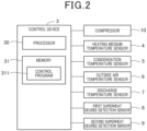
- FIG. 2 is a diagram showing the configuration of the control device 3.
- the control device 3 includes a processor 30 such as a central processing unit (CPU) or a micro processing unit (MPU), a memory 31, and an interface circuit to which other devices and sensors are connected.
- the control device 3 performs various functions of the control device 3 by the processor 30 reading and executing a control program 311 stored in the memory 31.
- the control program 311 is a program for controlling the heating medium circulation apparatus 100.
- the memory 31 is a memory that stores programs and data.
- the memory 31 stores the control program 311 and other data to be processed by the processor 30.
- the memory 31 has a nonvolatile storage area.
- the memory 31 also has a volatile storage area and constitutes a work area of the processor 30.
- the memory 31 is composed of, for example, a read only memory (ROM) and a random access memory (RAM).
- FIG. 2 shows a configuration in which the compressor 10, the heating medium temperature sensor 4, the condensation temperature sensor 5, the outside air temperature sensor 6, the discharge temperature sensor 7, the first superheat degree detection sensor 8, and the second superheat degree detection sensor 9 are connected to the control device 3.
- the devices connected to the control device 3 are not limited to these devices, and another device such as a motor that drives a fan may also be connected to the control device 3.
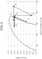
- control device 3 of the present embodiment performs the operation described below. First, the mechanism by which the discharge temperature of the compressor 10 excessively rises at startup of the compressor 10 will be described with reference to FIG. 3 .
- FIG. 3 is a Mollier diagram showing the state of the refrigerant.
- the heating medium circulation apparatus 100 of the present embodiment performs the following operation.
- the first opening degree is an opening degree that is set at startup of the compressor 10.
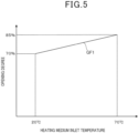
- a graph GF1 shows the relationship between the first opening degree and the heating medium inlet temperature. As shown in the graph GF1, the first opening degree is set larger as the heating medium inlet temperature increases.
- the control device 3 may make a determination by performing a calculation based on a predetermined algorithm or by referring to a table in which the magnitude of the first opening degree is determined for each heating medium inlet temperature.
- a first switching condition is that the temperature of the refrigerant flowing into the use side heat exchanger 11 falls below the heating medium inlet temperature.
- the control device 3 determines whether the first switching condition is satisfied based on a detected value of the heating medium temperature sensor 4 and a detected value of the condensation temperature sensor 5. More specifically, the control device 3 determines whether the temperature detected by the condensation temperature sensor 5 has fallen below the heating medium inlet temperature detected by the heating medium temperature sensor 4 after setting the opening degree of the decompression device 12 to the first opening degree. Then, when the control device 3 determines that the temperature of the refrigerant flowing into the use side heat exchanger 11 has fallen below the heating medium inlet temperature, the control device 3 determines that the first switching condition is satisfied.
- a second switching condition is that the superheat degree of the refrigerant suctioned by the compressor 10 falls below a predetermined threshold.
- An example of the predetermined threshold is 2 K (Kelvin).
- the control device 3 determines whether the second switching condition is satisfied based on a detected value of the first superheat degree detection sensor 8. More specifically, the control device 3 determines whether the superheat degree detected by the first superheat degree detection sensor 8 has fallen below the predetermined threshold after setting the opening degree of the decompression device 12 to the first opening degree. When the control device 3 determines that the superheat degree detected by the first superheat degree detection sensor 8 has fallen below the predetermined threshold, the control device 3 determines that the second switching condition is satisfied.
- a third switching condition is that the superheat degree of the refrigerant discharged by the compressor 10 exceeds a predetermined threshold.
- An example of the predetermined threshold is 5 K (Kelvin).
- the control device 3 determines whether the third switching condition is satisfied based on a detected value of the second superheat degree detection sensor 9. More specifically, the control device 3 determines whether the superheat degree detected by the second superheat degree detection sensor 9 has exceeded the predetermined threshold after setting the opening degree of the decompression device 12 to the first opening degree. When the control device 3 determines that the superheat degree detected by the second superheat degree detection sensor 9 has exceeded the predetermined threshold, the control device 3 determines that the third switching condition is satisfied.
- a fourth switching condition is that a first preset time elapses after startup of the compressor 10.
- the first preset time is a predetermined time and increases as the heating medium inlet temperature increases.
- the control device 3 determines the first preset time corresponding to the heating medium inlet temperature detected by the heating medium temperature sensor 4. The determination of the first preset time may be performed by performing a calculation based on a predetermined algorithm or by referring to a table in which the first preset time is determined in accordance with the heating medium inlet temperature. After determining the first preset time, the control device 3 determines whether the determined first preset time has elapsed after startup of the compressor 10. When the control device 3 determines that the first preset time has elapsed, the control device 3 determines that the fourth switching condition is satisfied.
- the first preset time is 3 minutes when the heating medium inlet temperature is +20°C and 7 minutes when the heating medium inlet temperature is +70°C
- a fifth switching condition is that a second preset time elapses after startup of the compressor 10.
- the second preset time is a predetermined time and increases as the outside air temperature decreases.
- the control device 3 determines the second preset time corresponding to the outside air temperature detected by the outside air temperature sensor 6. The determination of the second preset time may be performed by performing a calculation based on a predetermined algorithm or by referring to a table in which the second preset time is determined in accordance with the outside air temperature. After determining the second preset time, the control device 3 determines whether the determined second preset time has elapsed after startup of the compressor 10. When the control device 3 determines that the second preset time has elapsed, the control device 3 determines that the fifth switching condition is satisfied.
- the second preset time is 7 minutes when the outside air temperature is -20°C and 1 minute when the outside air temperature is +20°C.
- step S4 an affirmative determination may be made when any one of the above-mentioned first to fifth switching conditions is satisfied or when any multiple ones of the above-mentioned first to fifth switching conditions are satisfied.
- step S4 when the control device 3 determines that the switching condition is not satisfied (step S4: NO), the control device 3 performs the determination of step S4 again.
- step S4 determines that the switching condition is satisfied (step S4: YES)
- the control device 3 sets the opening degree of the decompression device 12 to the second opening degree based on a detected value of the heating medium temperature sensor 4 (step S5).
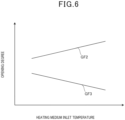
- FIG. 6 is a chart for explaining the second opening degree.
- the vertical axis represents the opening degree of the decompression device 12.
- a direction indicated by an arrow is the positive direction.
- the horizontal axis represents the heating medium inlet temperature.
- a direction indicated by an arrow is the positive direction.
- a graph GF2 shows the relationship between the first opening degree and the heating medium inlet temperature.
- a graph GF3 shows the relationship between the second opening degree and the heating medium inlet temperature.
- the second opening degree is an opening degree that is set after the first opening degree after the compressor 10 starts up. As shown in FIG. 6 , the second opening degree is set smaller as the heating medium inlet temperature increases. In addition, as shown in FIG. 6 , the second opening degree is smaller than the first opening degree.
- control device 3 may make a determination by performing a calculation based on a predetermined algorithm or by referring to a table in which the magnitude of the second opening degree is determined for each heating medium inlet temperature.
- control device 3 after the control device 3 sets the opening degree of the decompression device 12 to the second opening degree, the control device 3 feedback-controls the opening degree of the decompression device 12 so that the discharge temperature detected by the discharge temperature sensor 7 becomes a target temperature (step S6). Data of the target temperature of the discharge temperature is stored in the memory 31.
- the heating medium circulation apparatus 100 includes the refrigerant circuit 1 including the compressor 10, the use side heat exchanger 11, the decompression device 12, and the heat source side heat exchanger 13 that are connected in order.
- the heating medium circulation apparatus 100 also includes the heating medium circuit 2 through which the heating medium cooled or heated by the refrigerant from the compressor 10 in the use side heat exchanger 11 circulates.
- the heating medium circulation apparatus 100 also includes the heating medium temperature sensor 4 that detects the temperature of the heating medium flowing into the use side heat exchanger 11.
- the heating medium circulation apparatus 100 also includes the control device 3 that controls the decompression device 12.
- the control device 3 sets the opening degree of the decompression device 12 at startup of the compressor 10 to the first opening degree, the first opening degree being set larger as the temperature of the heating medium detected by the heating medium temperature sensor 4 increases.
- the control is performed so that the opening degree of the decompression device 12 at startup of the compressor 10 increases as the temperature of the heating medium flowing into the use side heat exchanger 11 increases.
- the refrigerant that has absorbed heat from the heating medium and vaporized in the use side heat exchanger 11 is not excessively decompressed by the decompression device 12, and excessive rise of the discharge temperature of the compressor 10 can be prevented.
- the reliability of the compressor 10 can be improved.
- the control device 3 sets the opening degree of the decompression device 12 to the second opening degree, the second opening degree being set smaller as the temperature of the heating medium detected by the heating medium temperature sensor 4 increases.
- the control device 3 increases the degree of decompression of the decompression device 12 by setting the opening degree of the decompression device 12 to the second opening degree when the switching condition is satisfied after the compressor 10 starts up.
- the temperature of the refrigerant passing through the use side heat exchanger 11 can be made higher than the temperature of the heating medium after the timing when the possibility of excessive rise of the discharge temperature is reduced, and efficient heat exchange can be performed in the use side heat exchanger 11.
- the heating medium circulation apparatus 100 includes the discharge temperature sensor 7 that detects the discharge temperature of the compressor 10.
- the control device 3 sets the opening degree of the decompression device 12 at the first opening degree until the switching condition is satisfied. After setting the opening degree of the decompression device 12 to the second opening degree, the control device 3 controls the decompression device 12 so that the discharge temperature of the compressor 10 becomes the target temperature based on the detected value of the discharge temperature sensor 7.
- the control device 3 maintains the opening degree of the decompression device 12 at the first opening degree until the switching condition is satisfied, thereby making it possible to effectively preventing excessive rise of the discharge temperature of the compressor 10 until the switching condition is satisfied.
- the control device 3 sets the opening degree of the decompression device 12 to the second opening degree. Accordingly, since the opening degree of the decompression device 12 is set to the second opening degree at an appropriate timing when the possibility of excessive rise of the discharge temperature of the compressor 10 is reduced, the system efficiency of the heating medium circulation apparatus 100 is further improved. Thus, the energy saving performance in the heating medium circulation apparatus 100 can be further improved.
- the heating medium circulation apparatus 100 includes the first superheat degree detection sensor 8 that detects the superheat degree of the refrigerant suctioned by the compressor 10.
- the switching condition is that the superheat degree detected by the first superheat degree detection sensor 8 falls below the predetermined threshold.
- the control device 3 sets the opening degree of the decompression device 12 to the second opening degree when the superheat degree of the refrigerant suctioned by the compressor 10 falls below the predetermined threshold. Accordingly, since the opening degree of the decompression device 12 is set to the second opening degree at an appropriate timing when the possibility of excessive rise of the discharge temperature of the compressor 10 is reduced, the system efficiency of the heating medium circulation apparatus 100 is further improved. Thus, the energy saving performance in the heating medium circulation apparatus 100 can be further improved.
- the heating medium circulation apparatus 100 includes the second superheat degree detection sensor 9 that detects the superheat degree of the refrigerant discharged by the compressor 10.
- the switching condition is that the superheat degree detected by the second superheat degree detection sensor 9 exceeds the predetermined threshold.
- the solubility of the refrigerant in lubricating oil of the compressor 10 is large.
- the solubility in the lubricating oil is large, the refrigerant inside the refrigerant circuit tends to be insufficient and the superheat degree of the refrigerant suctioned by the compressor 10 increases, thereby making it easier for the discharge temperature of the compressor 10 to excessively rise.
- the control device 3 can perform switching to the second opening degree at an appropriate timing when the discharge temperature of the compressor 10 is less likely to excessively rise.
- the reliability of the compressor 10 can be further improved.
- the switching condition is that the predetermined time elapses after startup of the compressor 10.
- the predetermined time increases as the temperature of the heating medium flowing into the use side heat exchanger 11 increases.
- the time for which the opening degree of the decompression device 12 is set at the first opening degree is increased as the heating medium inlet temperature increases.
- the refrigerant can be decompressed with the amount of decompression reduced until the superheat degree of the refrigerant that has passed through the use side heat exchanger 11 becomes small, and excessive rise of the discharge temperature of the compressor 10 can be more prevented.
- the reliability of the compressor 10 can be further improved.
- the switching condition is that the predetermined time elapses after startup of the compressor 10.
- the predetermined time increases as the outside air temperature decreases.
- the temperature of the shell of the compressor 10 decreases as the outside air temperature decreases, and the time from when the compressor 10 starts up to when the temperature of the refrigerant flowing through the use side heat exchanger 11 becomes higher than the temperature of the heating medium increases.
- the control device 3 increases the time for which the opening degree of the decompression device 12 is set at the first opening degree as the outside air temperature decreases. Accordingly, the refrigerant can be decompressed with the amount of decompression reduced until the superheat degree of the refrigerant that has passed through the use side heat exchanger 11 becomes small, and excessive rise of the discharge temperature of the compressor 10 can be more prevented.
- the reliability of the compressor 10 can be further improved.
- the first embodiment has been described as an example of the technique disclosed in the present application.
- the technique in the present disclosure is not limited thereto and also applicable to embodiments with changes, replacements, additions, omissions, and the like.
- the constituent elements described above in the first embodiment can be combined to constitute a new embodiment.
- other embodiments will be described as examples.
- the heating medium inlet temperature has been described as an example of the parameter for determining the first opening degree and the second opening degree.
- the outside air temperature may be included as the parameter for determining the first opening degree and the second opening degree. That is, in the other embodiment, the control device 3 sets the first opening degree larger as the outside air temperature detected by the outside air temperature sensor 6 decreases and sets the second opening degree smaller as the outside air temperature detected by the outside air temperature sensor 6 decreases.
- the first opening degree that is set when the heating medium inlet temperature is ⁇ °C is A% in the first embodiment
- the first opening degree that is set when the heating medium inlet temperature is ⁇ °C is set to an opening degree larger than A% as the outside air temperature decreases
- the first opening degree that is set when the heating medium inlet temperature is ⁇ °C is set to an opening degree smaller than A% as the outside air temperature increases.
- the heating medium inlet temperature is 20°C
- the first opening degree is set to 70%, following the graph GF1 in FIG. 5 .
- the first opening is set to an opening degree larger than 70% as the outside air temperature decreases.
- the first opening degree is set to 85%, following the graph GF1 in FIG. 5 .
- the first opening degree is set to an opening degree smaller than 85% as the outside air temperature increases (e.g., when the outside air temperature is -20°C, the first opening degree is set to 85%, and when the outside air temperature is +20°C, the first opening is set to 70%).
- the second opening degree that is set when the heating medium inlet temperature is ⁇ °C is B% in the first embodiment
- the second opening degree that is set when the heating medium inlet temperature is ⁇ °C is set to an opening degree smaller than B% as the outside air temperature decreases
- the second opening degree that is set when the heating medium inlet temperature is ⁇ °C is set to an opening degree larger than B% as the outside air temperature increases.
- control device 3 sets the first opening degree larger as the outside air temperature detected by the outside air temperature sensor 6 decreases and sets the second opening degree smaller as the outside air temperature detected by the outside air temperature sensor 6 decreases.
- the temperature of the shell of the compressor 10 decreases, and the temperature of the refrigerant flowing into the use side heat exchanger 11 further drops. That is, as the outside air temperature decreases, the temperature difference between the refrigerant and the heating medium in the use side heat exchanger 11 increases, and the superheat degree of the refrigerant flowing out of the use side heat exchanger 11 increases, thereby further increasing the possibility of excessive rise of the discharge temperature of the compressor 10.
- the first opening degree is set larger as the outside air temperature decreases, excessive decompression in the decompression device 12 can be prevented in accordance with the outside air temperature.
- the refrigerant is more largely decompressed by the decompression device 12 as the outside air temperature decreases after the second opening degree is set, the pressure of the refrigerant suctioned by the compressor 10 decreases, and the temperature of the refrigerant passing through the heat source side heat exchanger 13 becomes lower than the temperature of a heat source, which enables the refrigerant to efficiently absorb heat from the heat source.
- the first to fifth switching conditions have been described as examples of the switching condition for switching to the second opening degree.
- the switching condition for switching to the second opening degree may be any one or more of the first to fifth switching conditions. That is, in the other embodiment, the switching condition for switching to the second opening degree may be some of the first to the fifth switching conditions.
- the heating medium circulation apparatus 100 only needs to be equipped with a sensor necessary for determination on whether the switching condition is satisfied, and does not need to be equipped with all of the heating medium temperature sensor 4, the condensation temperature sensor 5, the outside air temperature sensor 6, the discharge temperature sensor 7, the first superheat degree detection sensor 8, and the second superheat degree detection sensor 9.
- the first superheat degree detection sensor 8 has been described as an example of the first superheat degree detection unit
- the second superheat degree detection sensor 9 has been described as an example of the second superheat degree detection unit
- the processor 30 may function as the first superheat degree detection unit and the second superheat degree detection unit.
- the heating medium circulation apparatus 100 is equipped with a sensor that detects the suction temperature of the compressor 10 and a sensor that detects the pressure of the refrigerant suctioned by the compressor 10 instead of the first superheat degree detection sensor 8 and is equipped with a sensor that detects the pressure of the refrigerant discharged by the compressor 10 instead of the second superheat degree detection sensor 9.
- the processor 30 in this case detects each superheat degree based on a detected value of the discharge temperature sensor 7 and detected values of the sensors included instead of the first superheat degree detection sensor 8 and the second superheat degree detection sensor 9.
- the processor 30 may be composed of a single processor or multiple processors. These processors may be hardware programmed to implement the corresponding functional part. That is, these processors may be composed of, for example, an application specific integrated circuit (ASIC) or a field programmable gate array (FPGA).
- ASIC application specific integrated circuit
- FPGA field programmable gate array
- control device 3 shown in FIG. 2 is an example, and the specific implementation mode is not limited to any particular mode. That is, it is not necessary to implement hardware corresponding to each part on an individual basis, and a single processor may execute a program to implement the function of each part.
- some of the functions implemented by software in the above-mentioned embodiments may be implemented by hardware, or some of the functions implemented by hardware may be implemented by software.
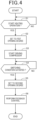
- step units of the operation shown in FIG. 4 are divided in accordance with the main processing details to facilitate understanding of the operation, and the operation is not limited by the way of dividing the processing units or names thereof. Division to more step units may be performed in accordance with the processing details. In addition, division may be performed in such a manner that one step unit includes more processes. In addition, the order of the steps may be interchanged as appropriate to the extent that it does not interfere with the gist of the present disclosure.
- a heating medium circulation apparatus including: a refrigerant circuit including a compressor, a use side heat exchanger, a decompression device, and a heat source side heat exchanger connected in order; a heating medium circuit through which a heating medium cooled or heated by a refrigerant from the compressor in the use side heat exchanger circulates; a heating medium temperature sensor that detects a temperature of the heating medium flowing into the use side heat exchanger; and a control device that controls the decompression device, in which the control device sets an opening degree of the decompression device at startup of the compressor to a first opening degree, the first opening degree being set larger as the temperature of the heating medium detected by the heating medium temperature sensor increases.
- the control is performed so that the opening degree of the decompression device at startup of the compressor increases as the temperature of the heating medium flowing into the use side heat exchanger increases.
- the refrigerant that has absorbed heat from the heating medium and vaporized in the use side heat exchanger is not excessively decompressed by the decompression device, and excessive rise of the discharge temperature of the compressor can be prevented.
- the reliability of the compressor can be improved.
- the degree of decompression of the decompression device can be increased at the timing when the temperature difference between the heating medium and the refrigerant becomes small in the use side heat exchanger and the possibility of excessive rise of the discharge temperature of the compressor is reduced. Accordingly, the temperature of the refrigerant passing through the use side heat exchanger can be made higher than the temperature of the heating medium after the timing when the possibility of excessive rise of the discharge temperature of the compressor is reduced, and efficient heat exchange can be performed in the use side heat exchanger. Thus, it is possible to improve the reliability of the compressor and improve the energy saving performance in the heating medium circulation apparatus.
- the heating medium circulation apparatus further including a discharge temperature sensor that detects a discharge temperature of the compressor, in which the control device sets the opening degree of the decompression device at the first opening degree until the switching condition is satisfied, and controls the decompression device so that the discharge temperature of the compressor becomes a target temperature based on a detected value of the discharge temperature sensor after setting the opening degree of the decompression device to the second opening degree.
- the heating medium circulation apparatus according to technique 2 or 3, further including an outside air temperature sensor that detects an outside air temperature, in which the control device sets the first opening degree larger as the outside air temperature detected by the outside air temperature sensor decreases and sets the second opening degree smaller as the outside air temperature detected by the outside air temperature sensor decreases.
- the first opening degree is set larger as the outside air temperature decreases, excessive decompression in the decompression device can be prevented in accordance with the outside air temperature.
- the refrigerant is more largely decompressed by the decompression device as the outside air temperature decreases after the second opening degree is set, the pressure of the refrigerant suctioned by the compressor decreases, and the temperature of the refrigerant passing through the heat source side heat exchanger becomes lower than the temperature of a heat source, which enables the refrigerant to efficiently absorb heat from the heat source.
- the heating medium circulation apparatus according to any one of techniques 2 to 4, further including a condensation temperature sensor that detects a condensation temperature of the refrigerant passing through the use side heat exchanger, in which the switching condition is that the temperature detected by the condensation temperature sensor exceeds the temperature detected by the heating medium temperature sensor.
- the opening degree of the decompression device can be set to the second opening degree at an appropriate timing when the possibility of excessive rise of the discharge temperature of the compressor is reduced, the system efficiency of the heating medium circulation apparatus is further improved.
- the energy saving performance in the heating medium circulation apparatus can be further improved.
- the heating medium circulation apparatus according to any one of techniques 2 to 5, further including a first superheat degree detection unit that detects a superheat degree of the refrigerant suctioned by the compressor, in which the switching condition is that the superheat degree detected by the first superheat degree detection unit falls below a predetermined threshold.
- the opening degree of the decompression device can be set to the second opening degree at an appropriate timing when the possibility of excessive rise of the discharge temperature of the compressor is reduced, the system efficiency of the heating medium circulation apparatus is further improved.
- the energy saving performance in the heating medium circulation apparatus can be further improved.
- switching to the second opening degree can be performed at the timing when the solubility of the refrigerant in the lubricating oil is small and the discharge temperature of the compressor is less likely to excessively rise.
- the reliability of the compressor can be further improved.
- the time for which the opening degree of the decompression device is set at the first opening degree can be increased as the temperature of the heating medium flowing into the use side heat exchanger increases.
- the refrigerant can be decompressed with the amount of decompression reduced until the superheat degree of the refrigerant that has passed through the use side heat exchanger becomes small, and excessive rise of the discharge temperature of the compressor can be more prevented.
- the reliability of the compressor can be further improved.
- the time for which the opening degree of the decompression device is set at the first opening degree is increased as the outside air temperature decreases. Accordingly, the refrigerant can be decompressed with the amount of decompression reduced until the superheat degree of the refrigerant that has passed through the use side heat exchanger becomes small, and excessive rise of the discharge temperature of the compressor can be more prevented. Thus, the reliability of the compressor can be further improved.
- the heating medium circulation apparatus can be used in an apparatus in which a heating medium and a refrigerant exchange heat, such as a hot water supply heater.
Landscapes
- Engineering & Computer Science (AREA)
- Physics & Mathematics (AREA)
- Mechanical Engineering (AREA)
- Thermal Sciences (AREA)
- General Engineering & Computer Science (AREA)
- Air Conditioning Control Device (AREA)
Abstract
Description
- The present disclosure relates to a heating medium circulation apparatus.
-
Japanese Patent Laid-Open No. 2000-346449 - The present disclosure provides a heating medium circulation apparatus that can improve the reliability of a compressor.
- A heating medium circulation apparatus in the present disclosure includes: a refrigerant circuit including a compressor, a use side heat exchanger, a decompression device, and a heat source side heat exchanger connected in order; a heating medium circuit through which a heating medium cooled or heated by a refrigerant from the compressor in the use side heat exchanger circulates; a heating medium temperature sensor that detects a temperature of the heating medium flowing into the use side heat exchanger; and a control device that controls the decompression device. The control device sets an opening degree of the decompression device at startup of the compressor to a first opening degree, the first opening degree being set larger as the temperature of the heating medium detected by the heating medium temperature sensor increases.
- The heating medium circulation apparatus in the present disclosure performs control so that the opening degree of the decompression device at startup of the compressor increases as the temperature of the heating medium flowing into the use side heat exchanger increases. Thus, the refrigerant that has absorbed heat from the heating medium and vaporized in the use side heat exchanger is not excessively decompressed by the decompression device, and excessive rise of the discharge temperature of the compressor can be prevented. Thus, the reliability of the compressor can be improved.
-
-
FIG. 1 is a diagram showing the configuration of a heating medium circulation apparatus in a first embodiment; -
FIG. 2 is a diagram showing the configuration of a control device in the first embodiment; -
FIG. 3 is a Mollier diagram showing the state of a refrigerant in the first embodiment; -
FIG. 4 is a flowchart showing the operation of the control device in the first embodiment; -
FIG. 5 is a chart for explaining a first opening degree in the first embodiment; and -
FIG. 6 is a chart for explaining a second opening degree in the first embodiment. - At the time when the inventors conceived of the present disclosure, there was a technique that controls the opening degree of a decompression device at startup of a compressor in a refrigerant circuit.
- However, although
Japanese Patent Laid-Open No. 2000-346449 Japanese Patent Laid-Open No. 2000-346449 - When the temperature of the water flowing into the refrigerant-to-water heat exchanger is higher than the temperature of the refrigerant, the refrigerant that has absorbed heat from the water and vaporized flows out of the refrigerant-to-water heat exchanger. In this case, as the temperature of the water flowing into the refrigerant-to-water heat exchanger increases, the superheat degree of the refrigerant flowing out of the refrigerant-to-water heat exchanger increases.
- From the above, in the configuration of
Japanese Patent Laid-Open No. 2000-346449 Japanese Patent Laid-Open No. 2000-346449 - Therefore, the present disclosure provides a heating medium circulation apparatus that can improve the reliability of a compressor.
- Hereinbelow, embodiments will be described in detail with reference to the drawings. Note that more details than necessary may be omitted. For example, detailed description of already well-known matters or repetitive description for substantially identical configurations may be omitted.
- Note that the accompanying drawings and the following description are provided to enable those skilled in the art to fully understand the present disclosure and are not intended to limit the subject matter described in the claims.
-
FIG. 1 is a diagram showing the configuration of a heatingmedium circulation apparatus 100. - The heating
medium circulation apparatus 100 includes anoutdoor unit 200, and anindoor unit 300. Theoutdoor unit 200 includes arefrigerant circuit 1, a part of aheating medium circuit 2, and acontrol device 3. Theindoor unit 300 includes a part of theheating medium circuit 2. - The
refrigerant circuit 1 is a vapor compression refrigeration cycle in which acompressor 10, a useside heat exchanger 11, adecompression device 12, and a heat sourceside heat exchanger 13 are connected in order through arefrigerant pipe 14. For example, propane, which is a flammable refrigerant, is used as a refrigerant circulating through therefrigerant circuit 1. - The
refrigerant circuit 1 is provided with a four-way valve 15 for performing switching between heating operation that generates hot water and cooling operation that generates cold water. InFIG. 1 , solid line arrows indicate a flowing direction of the refrigerant during heating operation, and dot-dash line arrows indicate a flowing direction of the refrigerant during cooling operation. - The
heating medium circuit 2 is a circuit in which the useside heat exchanger 11, an indoorside heat exchanger 20, and apump 21 that functions as a carrier device for a heating medium are connected in order through aheating medium pipe 22. Water or an antifreeze solution is used as the heating medium circulating through theheating medium circuit 2. InFIG. 1 , dash-dot-dot line arrows indicate a flowing direction of the heating medium. - The
control device 3 is a device that controls each part of the heatingmedium circulation apparatus 100. Various sensors included in the heatingmedium circulation apparatus 100 are connected to thecontrol device 3, and detected values are input to thecontrol device 3 from the various sensors connected thereto. - Next, the various sensors connected to the
control device 3 will be described. - The heating
medium circulation apparatus 100 includes a heatingmedium temperature sensor 4, acondensation temperature sensor 5 for the refrigerant, an outsideair temperature sensor 6, adischarge temperature sensor 7, a first superheatdegree detection sensor 8, and a second superheatdegree detection sensor 9. - The first superheat
degree detection sensor 8 is an example of "first superheat degree detection unit". The second superheatdegree detection sensor 9 is an example of "second superheat degree detection unit". - The heating
medium temperature sensor 4 is a sensor that detects the temperature of the heating medium flowing into the use side heat exchanger 11 (hereinbelow, referred to as "heating medium inlet temperature" as appropriate). The heatingmedium temperature sensor 4 is provided downstream of thepump 21 and upstream of the useside heat exchanger 11 in theheating medium pipe 22, based on the flowing direction of the heating medium. - The
condensation temperature sensor 5 is a sensor that detects the condensation temperature of the refrigerant passing through the useside heat exchanger 11, that is, the saturation temperature of the refrigerant discharged by thecompressor 10. Thecondensation temperature sensor 5 is provided downstream of thecompressor 10 and upstream of thedecompression device 12 in therefrigerant pipe 14, based on the flowing direction of the refrigerant. Note that the installation position of thecondensation temperature sensor 5 is not limited to the position inFIG. 1 and may be any position between thecompressor 10 and thedecompression device 12, based on the flowing direction of the refrigerant during heating operation. - The outside
air temperature sensor 6 is a sensor that detects the outside air temperature around a location where theoutdoor unit 200 is installed. The outsideair temperature sensor 6 is installed at a predetermined position on theoutdoor unit 200. The outsideair temperature sensor 6 may be installed inside theoutdoor unit 200 or outside theoutdoor unit 200. - The
discharge temperature sensor 7 is a sensor that detects the discharge temperature of thecompressor 10 during heating operation. The discharge temperature of thecompressor 10 is the temperature of the refrigerant discharged by thecompressor 10. Thedischarge temperature sensor 7 is provided upstream of the useside heat exchanger 11 and downstream of thecompressor 10, based on the flowing direction of the refrigerant during heating operation. - The first superheat
degree detection sensor 8 is a sensor that detects the superheat degree of the suction temperature of thecompressor 10 during heating operation. The suction temperature of thecompressor 10 is the temperature of the refrigerant suctioned by thecompressor 10. The first superheatdegree detection sensor 8 is equipped with a sensor that detects the suction temperature of thecompressor 10 and a sensor that detects the pressure of the refrigerant suctioned by thecompressor 10, and calculates the superheat degree from the difference between the detected suction temperature and the saturation temperature of the detected pressure. Here, the saturation temperature is derived from the formula of refrigerant properties. The first superheatdegree detection sensor 8 is provided downstream of the heat sourceside heat exchanger 13 and upstream of thecompressor 10, based on the flowing direction of the refrigerant during heating operation. - The second superheat
degree detection sensor 9 is a sensor that detects the superheat degree of the discharge temperature of thecompressor 10 during heating operation. The second superheatdegree detection sensor 9 is equipped with a sensor that detects the discharge temperature of thecompressor 10 and a sensor that detects the pressure of the refrigerant discharged by thecompressor 10, and calculates the superheat degree from the difference between the detected discharge temperature and the saturation temperature of the detected pressure. Here, the saturation temperature is derived from the formula of refrigerant properties. The second superheatdegree detection sensor 9 is provided upstream of the useside heat exchanger 11 and downstream of thecompressor 10, based on the flowing direction of the refrigerant during heating operation. - Next, the configuration of the
control device 3 will be described. -
FIG. 2 is a diagram showing the configuration of thecontrol device 3. - The
control device 3 includes aprocessor 30 such as a central processing unit (CPU) or a micro processing unit (MPU), amemory 31, and an interface circuit to which other devices and sensors are connected. Thecontrol device 3 performs various functions of thecontrol device 3 by theprocessor 30 reading and executing acontrol program 311 stored in thememory 31. Note that thecontrol program 311 is a program for controlling the heatingmedium circulation apparatus 100. - The
memory 31 is a memory that stores programs and data. Thememory 31 stores thecontrol program 311 and other data to be processed by theprocessor 30. Thememory 31 has a nonvolatile storage area. Thememory 31 also has a volatile storage area and constitutes a work area of theprocessor 30. Thememory 31 is composed of, for example, a read only memory (ROM) and a random access memory (RAM). - Various devices are connected to the
control device 3 via the interface circuit described above.FIG. 2 shows a configuration in which thecompressor 10, the heatingmedium temperature sensor 4, thecondensation temperature sensor 5, the outsideair temperature sensor 6, thedischarge temperature sensor 7, the first superheatdegree detection sensor 8, and the second superheatdegree detection sensor 9 are connected to thecontrol device 3. However, the devices connected to thecontrol device 3 are not limited to these devices, and another device such as a motor that drives a fan may also be connected to thecontrol device 3. - Next, the operation of the heating
medium circulation apparatus 100 according to the present embodiment will be described. - In order to prevent excessive rise of the discharge temperature of the
compressor 10 at startup of thecompressor 10, thecontrol device 3 of the present embodiment performs the operation described below. First, the mechanism by which the discharge temperature of thecompressor 10 excessively rises at startup of thecompressor 10 will be described with reference toFIG. 3 . -
FIG. 3 is a Mollier diagram showing the state of the refrigerant. - In the description of excessive rise of the discharge temperature, it is assumed that the outside air temperature is - 20°C, the temperature of the heating medium is +70°C, and the temperature of the refrigerant is +60°C.
- When the
compressor 10 starts up, the refrigerant inside thecompressor 10 is pressurized and goes into a state corresponding to a point P2 inFIG. 3 from a state corresponding to point P1 inFIG. 3 . However, the refrigerant that is condensed by a shell of thecompressor 10 having a low temperature due to the outside air and discharged by thecompressor 10 goes into a state corresponding to a point P3 inFIG. 3 , that is, a two-phase refrigerant. Since the temperature of the refrigerant is lower than the temperature of the heating medium in the useside heat exchanger 11, the refrigerant flowing into the useside heat exchanger 11 absorbs heat from the heating medium and vaporizes. Thus, the refrigerant flowing out of the useside heat exchanger 11 has a high superheat degree and low density. In the Mollier diagram ofFIG. 3 , the refrigerant flowing out of the useside heat exchanger 11 goes into a state corresponding to a point P4 inFIG. 3 . The refrigerant flowing out of the useside heat exchanger 11 is decompressed by thedecompression device 12. The refrigerant is more excessively decompressed as the opening degree of thedecompression device 12 decreases and goes into a state corresponding to a point P5 inFIG. 3 . The refrigerant decompressed by thedecompression device 12 absorbs heat in the heat sourceside heat exchanger 13. Thus, thecompressor 10 suctions and compresses the refrigerant having a high superheat degree. As a result, the refrigerant discharged by thecompressor 10 goes into a state corresponding to a point P6 inFIG. 3 , that is, a state away to the right from a saturated vapor line, and the discharge temperature of thecompressor 10 excessively rises. - As described above, under low outside air temperature conditions, the discharge temperature of the
compressor 10 may excessively rise when thecompressor 10 starts up. Thus, the heatingmedium circulation apparatus 100 of the present embodiment performs the following operation. -
FIG. 4 is a flowchart showing the operation of thecontrol device 3. - At the start of the flowchart in
FIG. 4 , the heatingmedium circulation apparatus 100 is in a stopped state. - The
control device 3 determines whether to start heating operation (step S1). For example, in step S1, when thecontrol device 3 receives a signal to start heating operation from a device that accepts operations related to the heatingmedium circulation apparatus 100 from a user, thecontrol device 3 makes an affirmative determination in step S1. - When the
control device 3 determines that heating operation is to be started (step S1: YES), thecontrol device 3 sets the opening degree of thedecompression device 12 to a first opening degree based on a detected value of the heating medium temperature sensor 4 (step S2). -
FIG. 5 is a chart for explaining the first opening degree. - In
FIG. 5 , the vertical axis represents the opening degree of thedecompression device 12. In addition, inFIG. 5 , the horizontal axis represents the heating medium inlet temperature. In the vertical axis ofFIG. 5 , the maximum opening degree of thedecompression device 12 is 100%. - The first opening degree is an opening degree that is set at startup of the
compressor 10. InFIG. 5 , a graph GF1 shows the relationship between the first opening degree and the heating medium inlet temperature. As shown in the graph GF1, the first opening degree is set larger as the heating medium inlet temperature increases. -
FIG. 5 shows a range from 20°C to 70°C as an example of a range of the heating medium inlet temperature. That is, in the example ofFIG. 5 , the lowest heating medium inlet temperature is 20°C, and the highest heating medium inlet temperature is 70°C. In the case ofFIG. 5 , when the heating medium inlet temperature is 20°C, the first opening degree is set to an opening degree of 70%. In the case ofFIG. 5 , when the heating medium inlet temperature is 70°C, the first opening degree is set to an opening degree of 85%. In the case ofFIG. 5 , when the heating medium inlet temperature is higher than 20°C and lower than 70°C, the first opening degree is set to a larger opening degree as the heating medium inlet temperature increases. - Although the example of
FIG. 5 shows that the first opening degree is set proportionally larger as the heating medium inlet temperature increases, the relationship between the heating medium inlet temperature and the magnitude of the first opening degree is not limited to the proportional relationship. - The range of the first opening degree shown in
FIG. 5 is merely an example and is not limited to the range from 70% to 85%, as long as it is a range in which the first opening degree increases as the heating medium inlet temperature increases. In addition, the range of the heating medium inlet temperature that defines the range of the first opening degree shown inFIG. 5 is not limited to the range from 20°C to 70°C. The range of the first opening degree may be defined by a broader range of the heating medium inlet temperature or a narrower range of the heating medium inlet temperature. - In determining the first opening degree, the
control device 3 may make a determination by performing a calculation based on a predetermined algorithm or by referring to a table in which the magnitude of the first opening degree is determined for each heating medium inlet temperature. - Returning to the description of the flowchart shown in
FIG. 4 , after setting the opening degree of thedecompression device 12 to the first opening degree, thecontrol device 3 starts driving the compressor 10 (step S3). That is, in step S3, thecontrol device 3 starts up thecompressor 10. - Next, the
control device 3 determines whether a switching condition for switching the opening degree of thedecompression device 12 from the first opening degree to the second opening degree is satisfied (step S4). The second opening degree will be described further below. - Here, a plurality of switching conditions will be described.
- A first switching condition is that the temperature of the refrigerant flowing into the use
side heat exchanger 11 falls below the heating medium inlet temperature. Thecontrol device 3 determines whether the first switching condition is satisfied based on a detected value of the heatingmedium temperature sensor 4 and a detected value of thecondensation temperature sensor 5. More specifically, thecontrol device 3 determines whether the temperature detected by thecondensation temperature sensor 5 has fallen below the heating medium inlet temperature detected by the heatingmedium temperature sensor 4 after setting the opening degree of thedecompression device 12 to the first opening degree. Then, when thecontrol device 3 determines that the temperature of the refrigerant flowing into the useside heat exchanger 11 has fallen below the heating medium inlet temperature, thecontrol device 3 determines that the first switching condition is satisfied. - A second switching condition is that the superheat degree of the refrigerant suctioned by the
compressor 10 falls below a predetermined threshold. An example of the predetermined threshold is 2 K (Kelvin). Thecontrol device 3 determines whether the second switching condition is satisfied based on a detected value of the first superheatdegree detection sensor 8. More specifically, thecontrol device 3 determines whether the superheat degree detected by the first superheatdegree detection sensor 8 has fallen below the predetermined threshold after setting the opening degree of thedecompression device 12 to the first opening degree. When thecontrol device 3 determines that the superheat degree detected by the first superheatdegree detection sensor 8 has fallen below the predetermined threshold, thecontrol device 3 determines that the second switching condition is satisfied. - A third switching condition is that the superheat degree of the refrigerant discharged by the
compressor 10 exceeds a predetermined threshold. An example of the predetermined threshold is 5 K (Kelvin). Thecontrol device 3 determines whether the third switching condition is satisfied based on a detected value of the second superheatdegree detection sensor 9. More specifically, thecontrol device 3 determines whether the superheat degree detected by the second superheatdegree detection sensor 9 has exceeded the predetermined threshold after setting the opening degree of thedecompression device 12 to the first opening degree. When thecontrol device 3 determines that the superheat degree detected by the second superheatdegree detection sensor 9 has exceeded the predetermined threshold, thecontrol device 3 determines that the third switching condition is satisfied. - A fourth switching condition is that a first preset time elapses after startup of the
compressor 10. The first preset time is a predetermined time and increases as the heating medium inlet temperature increases. After setting the opening degree of thedecompression device 12 to the first opening degree, thecontrol device 3 determines the first preset time corresponding to the heating medium inlet temperature detected by the heatingmedium temperature sensor 4. The determination of the first preset time may be performed by performing a calculation based on a predetermined algorithm or by referring to a table in which the first preset time is determined in accordance with the heating medium inlet temperature. After determining the first preset time, thecontrol device 3 determines whether the determined first preset time has elapsed after startup of thecompressor 10. When thecontrol device 3 determines that the first preset time has elapsed, thecontrol device 3 determines that the fourth switching condition is satisfied. - For example, the first preset time is 3 minutes when the heating medium inlet temperature is +20°C and 7 minutes when the heating medium inlet temperature is +70°C
- A fifth switching condition is that a second preset time elapses after startup of the
compressor 10. The second preset time is a predetermined time and increases as the outside air temperature decreases. After setting the opening degree of thedecompression device 12 to the first opening degree, thecontrol device 3 determines the second preset time corresponding to the outside air temperature detected by the outsideair temperature sensor 6. The determination of the second preset time may be performed by performing a calculation based on a predetermined algorithm or by referring to a table in which the second preset time is determined in accordance with the outside air temperature. After determining the second preset time, thecontrol device 3 determines whether the determined second preset time has elapsed after startup of thecompressor 10. When thecontrol device 3 determines that the second preset time has elapsed, thecontrol device 3 determines that the fifth switching condition is satisfied. - For example, the second preset time is 7 minutes when the outside air temperature is -20°C and 1 minute when the outside air temperature is +20°C.
- In step S4, an affirmative determination may be made when any one of the above-mentioned first to fifth switching conditions is satisfied or when any multiple ones of the above-mentioned first to fifth switching conditions are satisfied.
- Returning to the description of step S4, when the
control device 3 determines that the switching condition is not satisfied (step S4: NO), thecontrol device 3 performs the determination of step S4 again. - On the other hand, when the
control device 3 determines that the switching condition is satisfied (step S4: YES), thecontrol device 3 sets the opening degree of thedecompression device 12 to the second opening degree based on a detected value of the heating medium temperature sensor 4 (step S5). -
FIG. 6 is a chart for explaining the second opening degree. - In
FIG. 6 , the vertical axis represents the opening degree of thedecompression device 12. In the vertical axis ofFIG. 6 , a direction indicated by an arrow is the positive direction. In addition, inFIG. 6 , the horizontal axis represents the heating medium inlet temperature. In the horizontal axis ofFIG. 6 , a direction indicated by an arrow is the positive direction. InFIG. 6 , a graph GF2 shows the relationship between the first opening degree and the heating medium inlet temperature. In addition, inFIG. 6 , a graph GF3 shows the relationship between the second opening degree and the heating medium inlet temperature. - The second opening degree is an opening degree that is set after the first opening degree after the
compressor 10 starts up. As shown inFIG. 6 , the second opening degree is set smaller as the heating medium inlet temperature increases. In addition, as shown inFIG. 6 , the second opening degree is smaller than the first opening degree. - In determining the second opening degree, the
control device 3 may make a determination by performing a calculation based on a predetermined algorithm or by referring to a table in which the magnitude of the second opening degree is determined for each heating medium inlet temperature. - Returning to the description of the flowchart shown in
FIG. 4 , after thecontrol device 3 sets the opening degree of thedecompression device 12 to the second opening degree, thecontrol device 3 feedback-controls the opening degree of thedecompression device 12 so that the discharge temperature detected by thedischarge temperature sensor 7 becomes a target temperature (step S6). Data of the target temperature of the discharge temperature is stored in thememory 31. - As described above, the heating
medium circulation apparatus 100 includes therefrigerant circuit 1 including thecompressor 10, the useside heat exchanger 11, thedecompression device 12, and the heat sourceside heat exchanger 13 that are connected in order. The heatingmedium circulation apparatus 100 also includes theheating medium circuit 2 through which the heating medium cooled or heated by the refrigerant from thecompressor 10 in the useside heat exchanger 11 circulates. The heatingmedium circulation apparatus 100 also includes the heatingmedium temperature sensor 4 that detects the temperature of the heating medium flowing into the useside heat exchanger 11. The heatingmedium circulation apparatus 100 also includes thecontrol device 3 that controls thedecompression device 12. Thecontrol device 3 sets the opening degree of thedecompression device 12 at startup of thecompressor 10 to the first opening degree, the first opening degree being set larger as the temperature of the heating medium detected by the heatingmedium temperature sensor 4 increases. - According to this, the control is performed so that the opening degree of the
decompression device 12 at startup of thecompressor 10 increases as the temperature of the heating medium flowing into the useside heat exchanger 11 increases. Thus, the refrigerant that has absorbed heat from the heating medium and vaporized in the useside heat exchanger 11 is not excessively decompressed by thedecompression device 12, and excessive rise of the discharge temperature of thecompressor 10 can be prevented. Thus, the reliability of thecompressor 10 can be improved. - When the switching condition for switching the opening degree of the
decompression device 12 is satisfied after thecompressor 10 starts up, thecontrol device 3 sets the opening degree of thedecompression device 12 to the second opening degree, the second opening degree being set smaller as the temperature of the heating medium detected by the heatingmedium temperature sensor 4 increases. - After the
compressor 10 starts up, the temperature of the shell of thecompressor 10 gradually rises. Thus, the temperature of the refrigerant flowing into the useside heat exchanger 11 gradually rises, and the temperature difference between the heating medium and the refrigerant decreases in the useside heat exchanger 11. Thus, the refrigerant is less likely to vaporize in the useside heat exchanger 11, and the possibility of excessive rise of the discharge temperature of thecompressor 10 is reduced. Therefore, thecontrol device 3 increases the degree of decompression of thedecompression device 12 by setting the opening degree of thedecompression device 12 to the second opening degree when the switching condition is satisfied after thecompressor 10 starts up. Accordingly, the temperature of the refrigerant passing through the useside heat exchanger 11 can be made higher than the temperature of the heating medium after the timing when the possibility of excessive rise of the discharge temperature is reduced, and efficient heat exchange can be performed in the useside heat exchanger 11. Thus, it is possible to improve the reliability of thecompressor 10 and improve the energy saving performance in the heatingmedium circulation apparatus 100. - The heating
medium circulation apparatus 100 includes thedischarge temperature sensor 7 that detects the discharge temperature of thecompressor 10. Thecontrol device 3 sets the opening degree of thedecompression device 12 at the first opening degree until the switching condition is satisfied. After setting the opening degree of thedecompression device 12 to the second opening degree, thecontrol device 3 controls thedecompression device 12 so that the discharge temperature of thecompressor 10 becomes the target temperature based on the detected value of thedischarge temperature sensor 7. - Immediately after the
compressor 10 starts up, it takes time for the discharge temperature of thecompressor 10 to rise due to factors such as the heat capacity of thecompressor 10 and other constituent components. Thus, when the opening degree of thedecompression device 12 is controlled so that the discharge temperature of thecompressor 10 becomes the target temperature, thedecompression device 12 may be excessively closed, and the discharge temperature of thecompressor 10 may excessively rise. Thus, thecontrol device 3 maintains the opening degree of thedecompression device 12 at the first opening degree until the switching condition is satisfied, thereby making it possible to effectively preventing excessive rise of the discharge temperature of thecompressor 10 until the switching condition is satisfied. In addition, since the opening degree of thedecompression device 12 is controlled so that the discharge temperature becomes the target temperature after the second opening degree is set, control on thedecompression device 12 can be performed with high system efficiency for the heatingmedium circulation apparatus 100. As described above, it is possible to further improve the reliability of thecompressor 10 and further improve the energy saving performance in the heatingmedium circulation apparatus 100. - The heating
medium circulation apparatus 100 includes thecondensation temperature sensor 5 that detects the condensation temperature of the refrigerant passing through the useside heat exchanger 11. The switching condition is that the temperature detected by thecondensation temperature sensor 5 exceeds the temperature detected by the heatingmedium temperature sensor 4. - When the temperature of the refrigerant flowing into the use
side heat exchanger 11 is higher than the heating medium inlet temperature, the refrigerant heats the heating medium in the useside heat exchanger 11. Thus, in this case, since the refrigerant does not absorb heat and vaporize in the useside heat exchanger 11, the possibility of excessive rise of the discharge temperature of thecompressor 10 is reduced. Therefore, in this case, thecontrol device 3 sets the opening degree of thedecompression device 12 to the second opening degree. Accordingly, since the opening degree of thedecompression device 12 is set to the second opening degree at an appropriate timing when the possibility of excessive rise of the discharge temperature of thecompressor 10 is reduced, the system efficiency of the heatingmedium circulation apparatus 100 is further improved. Thus, the energy saving performance in the heatingmedium circulation apparatus 100 can be further improved. - The heating
medium circulation apparatus 100 includes the first superheatdegree detection sensor 8 that detects the superheat degree of the refrigerant suctioned by thecompressor 10. The switching condition is that the superheat degree detected by the first superheatdegree detection sensor 8 falls below the predetermined threshold. - When the superheat degree of the refrigerant suctioned by the
compressor 10 decreases, the possibility of excessive rise of the discharge temperature of thecompressor 10 is reduced. Thus, thecontrol device 3 sets the opening degree of thedecompression device 12 to the second opening degree when the superheat degree of the refrigerant suctioned by thecompressor 10 falls below the predetermined threshold. Accordingly, since the opening degree of thedecompression device 12 is set to the second opening degree at an appropriate timing when the possibility of excessive rise of the discharge temperature of thecompressor 10 is reduced, the system efficiency of the heatingmedium circulation apparatus 100 is further improved. Thus, the energy saving performance in the heatingmedium circulation apparatus 100 can be further improved. - The heating
medium circulation apparatus 100 includes the second superheatdegree detection sensor 9 that detects the superheat degree of the refrigerant discharged by thecompressor 10. The switching condition is that the superheat degree detected by the second superheatdegree detection sensor 9 exceeds the predetermined threshold. - Generally, when the superheat degree of the discharge temperature of the
compressor 10 is small, the solubility of the refrigerant in lubricating oil of thecompressor 10 is large. When the solubility in the lubricating oil is large, the refrigerant inside the refrigerant circuit tends to be insufficient and the superheat degree of the refrigerant suctioned by thecompressor 10 increases, thereby making it easier for the discharge temperature of thecompressor 10 to excessively rise. Thus, by setting the opening degree of thedecompression device 12 to the second opening degree at the timing when the solubility in the lubricating oil is small, thecontrol device 3 can perform switching to the second opening degree at an appropriate timing when the discharge temperature of thecompressor 10 is less likely to excessively rise. Thus, the reliability of thecompressor 10 can be further improved. - The switching condition is that the predetermined time elapses after startup of the
compressor 10. The predetermined time increases as the temperature of the heating medium flowing into the useside heat exchanger 11 increases. - According to this, the time for which the opening degree of the
decompression device 12 is set at the first opening degree is increased as the heating medium inlet temperature increases. Thus, the refrigerant can be decompressed with the amount of decompression reduced until the superheat degree of the refrigerant that has passed through the useside heat exchanger 11 becomes small, and excessive rise of the discharge temperature of thecompressor 10 can be more prevented. Thus, the reliability of thecompressor 10 can be further improved. - The switching condition is that the predetermined time elapses after startup of the
compressor 10. The predetermined time increases as the outside air temperature decreases. - The temperature of the shell of the
compressor 10 decreases as the outside air temperature decreases, and the time from when thecompressor 10 starts up to when the temperature of the refrigerant flowing through the useside heat exchanger 11 becomes higher than the temperature of the heating medium increases. Thus, thecontrol device 3 increases the time for which the opening degree of thedecompression device 12 is set at the first opening degree as the outside air temperature decreases. Accordingly, the refrigerant can be decompressed with the amount of decompression reduced until the superheat degree of the refrigerant that has passed through the useside heat exchanger 11 becomes small, and excessive rise of the discharge temperature of thecompressor 10 can be more prevented. Thus, the reliability of thecompressor 10 can be further improved. - As above, the first embodiment has been described as an example of the technique disclosed in the present application. However, the technique in the present disclosure is not limited thereto and also applicable to embodiments with changes, replacements, additions, omissions, and the like. In addition, the constituent elements described above in the first embodiment can be combined to constitute a new embodiment. Thus, hereinbelow, other embodiments will be described as examples.
- In the above embodiment, the heating medium inlet temperature has been described as an example of the parameter for determining the first opening degree and the second opening degree. In another embodiment, in addition to the heating medium inlet temperature, the outside air temperature may be included as the parameter for determining the first opening degree and the second opening degree. That is, in the other embodiment, the
control device 3 sets the first opening degree larger as the outside air temperature detected by the outsideair temperature sensor 6 decreases and sets the second opening degree smaller as the outside air temperature detected by the outsideair temperature sensor 6 decreases. - That is, when the first opening degree that is set when the heating medium inlet temperature is α°C is A% in the first embodiment, in the other embodiment, the first opening degree that is set when the heating medium inlet temperature is α°C is set to an opening degree larger than A% as the outside air temperature decreases, and the first opening degree that is set when the heating medium inlet temperature is α°C is set to an opening degree smaller than A% as the outside air temperature increases. For example, when the heating medium inlet temperature is 20°C, in the first embodiment, the first opening degree is set to 70%, following the graph GF1 in
FIG. 5 . In the other embodiment, when the heating medium inlet temperature is 20°C, the first opening is set to an opening degree larger than 70% as the outside air temperature decreases. In addition, for example, when the heating medium inlet temperature is 70°C, in the first embodiment, the first opening degree is set to 85%, following the graph GF1 inFIG. 5 . In the other embodiment, when the heating medium inlet temperature is 70°C, the first opening degree is set to an opening degree smaller than 85% as the outside air temperature increases (e.g., when the outside air temperature is -20°C, the first opening degree is set to 85%, and when the outside air temperature is +20°C, the first opening is set to 70%). - In addition, when the second opening degree that is set when the heating medium inlet temperature is β°C is B% in the first embodiment, in the other embodiment, the second opening degree that is set when the heating medium inlet temperature is β°C is set to an opening degree smaller than B% as the outside air temperature decreases, and the second opening degree that is set when the heating medium inlet temperature is β°C is set to an opening degree larger than B% as the outside air temperature increases.
- As described above, in the other embodiment described above, the
control device 3 sets the first opening degree larger as the outside air temperature detected by the outsideair temperature sensor 6 decreases and sets the second opening degree smaller as the outside air temperature detected by the outsideair temperature sensor 6 decreases. - As the outside air temperature decreases, the temperature of the shell of the
compressor 10 decreases, and the temperature of the refrigerant flowing into the useside heat exchanger 11 further drops. That is, as the outside air temperature decreases, the temperature difference between the refrigerant and the heating medium in the useside heat exchanger 11 increases, and the superheat degree of the refrigerant flowing out of the useside heat exchanger 11 increases, thereby further increasing the possibility of excessive rise of the discharge temperature of thecompressor 10. Thus, in the other embodiment, since the first opening degree is set larger as the outside air temperature decreases, excessive decompression in thedecompression device 12 can be prevented in accordance with the outside air temperature. Thus, it is possible to prevent excessive rise of the discharge temperature of thecompressor 10 without depending on the outside air temperature and further improve the reliability of thecompressor 10. - In addition, since the refrigerant is more largely decompressed by the
decompression device 12 as the outside air temperature decreases after the second opening degree is set, the pressure of the refrigerant suctioned by thecompressor 10 decreases, and the temperature of the refrigerant passing through the heat sourceside heat exchanger 13 becomes lower than the temperature of a heat source, which enables the refrigerant to efficiently absorb heat from the heat source. - In the above first embodiment, the first to fifth switching conditions have been described as examples of the switching condition for switching to the second opening degree. In another embodiment, the switching condition for switching to the second opening degree may be any one or more of the first to fifth switching conditions. That is, in the other embodiment, the switching condition for switching to the second opening degree may be some of the first to the fifth switching conditions. In this case, the heating
medium circulation apparatus 100 only needs to be equipped with a sensor necessary for determination on whether the switching condition is satisfied, and does not need to be equipped with all of the heatingmedium temperature sensor 4, thecondensation temperature sensor 5, the outsideair temperature sensor 6, thedischarge temperature sensor 7, the first superheatdegree detection sensor 8, and the second superheatdegree detection sensor 9. - In the above first embodiment, the first superheat
degree detection sensor 8 has been described as an example of the first superheat degree detection unit, and the second superheatdegree detection sensor 9 has been described as an example of the second superheat degree detection unit. In another embodiment, theprocessor 30 may function as the first superheat degree detection unit and the second superheat degree detection unit. In this case, the heatingmedium circulation apparatus 100 is equipped with a sensor that detects the suction temperature of thecompressor 10 and a sensor that detects the pressure of the refrigerant suctioned by thecompressor 10 instead of the first superheatdegree detection sensor 8 and is equipped with a sensor that detects the pressure of the refrigerant discharged by thecompressor 10 instead of the second superheatdegree detection sensor 9. Theprocessor 30 in this case detects each superheat degree based on a detected value of thedischarge temperature sensor 7 and detected values of the sensors included instead of the first superheatdegree detection sensor 8 and the second superheatdegree detection sensor 9. - The
processor 30 may be composed of a single processor or multiple processors. These processors may be hardware programmed to implement the corresponding functional part. That is, these processors may be composed of, for example, an application specific integrated circuit (ASIC) or a field programmable gate array (FPGA). - The configuration of the
control device 3 shown inFIG. 2 is an example, and the specific implementation mode is not limited to any particular mode. That is, it is not necessary to implement hardware corresponding to each part on an individual basis, and a single processor may execute a program to implement the function of each part. In addition, some of the functions implemented by software in the above-mentioned embodiments may be implemented by hardware, or some of the functions implemented by hardware may be implemented by software. - The step units of the operation shown in
FIG. 4 are divided in accordance with the main processing details to facilitate understanding of the operation, and the operation is not limited by the way of dividing the processing units or names thereof. Division to more step units may be performed in accordance with the processing details. In addition, division may be performed in such a manner that one step unit includes more processes. In addition, the order of the steps may be interchanged as appropriate to the extent that it does not interfere with the gist of the present disclosure. - Since the embodiments described above are intended to exemplify the technique in the present disclosure, various changes, replacements, additions, omissions, and the like can be made within the scope of the claims or a scope equivalent thereto.
- The above description of the embodiments discloses the following techniques.
- (Technique 1) A heating medium circulation apparatus including: a refrigerant circuit including a compressor, a use side heat exchanger, a decompression device, and a heat source side heat exchanger connected in order; a heating medium circuit through which a heating medium cooled or heated by a refrigerant from the compressor in the use side heat exchanger circulates; a heating medium temperature sensor that detects a temperature of the heating medium flowing into the use side heat exchanger; and a control device that controls the decompression device, in which the control device sets an opening degree of the decompression device at startup of the compressor to a first opening degree, the first opening degree being set larger as the temperature of the heating medium detected by the heating medium temperature sensor increases.
- According to this, the control is performed so that the opening degree of the decompression device at startup of the compressor increases as the temperature of the heating medium flowing into the use side heat exchanger increases. Thus, the refrigerant that has absorbed heat from the heating medium and vaporized in the use side heat exchanger is not excessively decompressed by the decompression device, and excessive rise of the discharge temperature of the compressor can be prevented. Thus, the reliability of the compressor can be improved.
- (Technique 2) The heating medium circulation apparatus according to
technique 1, in which the control device sets the opening degree of the decompression device to a second opening degree when a switching condition for switching the opening degree of the decompression device is satisfied after the compressor starts up, the second opening degree being set smaller as the temperature of the heating medium detected by the heating medium temperature sensor increases. - According to this, the degree of decompression of the decompression device can be increased at the timing when the temperature difference between the heating medium and the refrigerant becomes small in the use side heat exchanger and the possibility of excessive rise of the discharge temperature of the compressor is reduced. Accordingly, the temperature of the refrigerant passing through the use side heat exchanger can be made higher than the temperature of the heating medium after the timing when the possibility of excessive rise of the discharge temperature of the compressor is reduced, and efficient heat exchange can be performed in the use side heat exchanger. Thus, it is possible to improve the reliability of the compressor and improve the energy saving performance in the heating medium circulation apparatus.
- (Technique 3) The heating medium circulation apparatus according to
technique 2, further including a discharge temperature sensor that detects a discharge temperature of the compressor, in which the control device sets the opening degree of the decompression device at the first opening degree until the switching condition is satisfied, and controls the decompression device so that the discharge temperature of the compressor becomes a target temperature based on a detected value of the discharge temperature sensor after setting the opening degree of the decompression device to the second opening degree. - According to this, it is possible to effectively preventing excessive rise of the discharge temperature of the compressor until the switching condition is satisfied by maintaining the opening degree of the decompression device at the first opening degree until the switching condition is satisfied. In addition, since the opening degree of the decompression device is controlled so that the discharge temperature becomes the target temperature after the second opening degree is set, control on the decompression device can be performed with high system efficiency for the heating medium circulation apparatus. Thus, it is possible to further improve the reliability of the compressor and further improve the energy saving performance in the heating medium circulation apparatus.
- (Technique 4) The heating medium circulation apparatus according to
technique - According to this, since the first opening degree is set larger as the outside air temperature decreases, excessive decompression in the decompression device can be prevented in accordance with the outside air temperature. Thus, it is possible to prevent excessive rise of the discharge temperature of the compressor without depending on the outside air temperature and further improve the reliability of the compressor. In addition, since the refrigerant is more largely decompressed by the decompression device as the outside air temperature decreases after the second opening degree is set, the pressure of the refrigerant suctioned by the compressor decreases, and the temperature of the refrigerant passing through the heat source side heat exchanger becomes lower than the temperature of a heat source, which enables the refrigerant to efficiently absorb heat from the heat source.
- (Technique 5) The heating medium circulation apparatus according to any one of
techniques 2 to 4, further including a condensation temperature sensor that detects a condensation temperature of the refrigerant passing through the use side heat exchanger, in which the switching condition is that the temperature detected by the condensation temperature sensor exceeds the temperature detected by the heating medium temperature sensor. - According to this, since the opening degree of the decompression device can be set to the second opening degree at an appropriate timing when the possibility of excessive rise of the discharge temperature of the compressor is reduced, the system efficiency of the heating medium circulation apparatus is further improved. Thus, the energy saving performance in the heating medium circulation apparatus can be further improved.
- (Technique 6) The heating medium circulation apparatus according to any one of
techniques 2 to 5, further including a first superheat degree detection unit that detects a superheat degree of the refrigerant suctioned by the compressor, in which the switching condition is that the superheat degree detected by the first superheat degree detection unit falls below a predetermined threshold. - According to this, since the opening degree of the decompression device can be set to the second opening degree at an appropriate timing when the possibility of excessive rise of the discharge temperature of the compressor is reduced, the system efficiency of the heating medium circulation apparatus is further improved. Thus, the energy saving performance in the heating medium circulation apparatus can be further improved.
- (Technique 7) The heating medium circulation apparatus according to any one of
techniques 2 to 6, further including a second superheat degree detection unit that detects a superheat degree of the refrigerant discharged by the compressor, in which the switching condition is that the superheat degree detected by the second superheat degree detection unit exceeds a predetermined threshold. - According to this, switching to the second opening degree can be performed at the timing when the solubility of the refrigerant in the lubricating oil is small and the discharge temperature of the compressor is less likely to excessively rise. Thus, the reliability of the compressor can be further improved.
- (Technique 8) The heating medium circulation apparatus according to any one of
techniques 2 to 7, in which the switching condition is that a predetermined time elapses after startup of the compressor, and the predetermined time increases as the temperature of the heating medium flowing into the use side heat exchanger increases. - According to this, the time for which the opening degree of the decompression device is set at the first opening degree can be increased as the temperature of the heating medium flowing into the use side heat exchanger increases. Thus, the refrigerant can be decompressed with the amount of decompression reduced until the superheat degree of the refrigerant that has passed through the use side heat exchanger becomes small, and excessive rise of the discharge temperature of the compressor can be more prevented. Thus, the reliability of the compressor can be further improved.
- (Technique 9) The heating medium circulation apparatus according to any one of
techniques 2 to 8, in which the switching condition is that a predetermined time elapses after startup of the compressor, and the predetermined time increases as the outside air temperature decreases. - According to this, the time for which the opening degree of the decompression device is set at the first opening degree is increased as the outside air temperature decreases. Accordingly, the refrigerant can be decompressed with the amount of decompression reduced until the superheat degree of the refrigerant that has passed through the use side heat exchanger becomes small, and excessive rise of the discharge temperature of the compressor can be more prevented. Thus, the reliability of the compressor can be further improved.
- As described above, the heating medium circulation apparatus according to the present invention can be used in an apparatus in which a heating medium and a refrigerant exchange heat, such as a hot water supply heater.
-
- 1 refrigerant circuit
- 2 heating medium circuit
- 3 control device
- 4 heating medium temperature sensor
- 5 condensation temperature sensor
- 6 outside air temperature sensor
- 7 discharge temperature sensor
- 8 first superheat degree detection sensor (first superheat degree detection unit)
- 9 second superheat degree detection sensor (second superheat degree detection unit)
- 10 compressor
- 11 use side heat exchanger
- 12 decompression device
- 13 heat source side heat exchanger
- 14 refrigerant pipe
- 15 four-way valve
- 20 indoor side heat exchanger
- 21 pump
- 22 heating medium pipe
- 30 processor
- 31 memory
- 100 heating medium circulation apparatus
- 200 outdoor unit
- 300 indoor unit
- 311 control program
- GF1 to GF3 graph
- P1 to P6 point
Claims (9)
- A heating medium circulation apparatus characterized by comprising:a refrigerant circuit including a compressor (10), a use side heat exchanger (11), a decompression device (12), and a heat source side heat exchanger (13) connected in order;a heating medium circuit (2) through which a heating medium cooled or heated by a refrigerant from the compressor in the use side heat exchanger circulates;a heating medium temperature sensor (4) that detects a temperature of the heating medium flowing into the use side heat exchanger; anda control device (3) that controls the decompression device, whereinthe control device sets an opening degree of the decompression device at startup of the compressor to a first opening degree, the first opening degree being set larger as the temperature of the heating medium detected by the heating medium temperature sensor increases.
- The heating medium circulation apparatus according to claim 1, whereinthe control devicesets the opening degree of the decompression device at the first opening degree during a period from when the compressor starts up to when a switching condition for switching the opening degree of the decompression device is satisfied, andsets the opening degree of the decompression device to a second opening degree when the switching condition is satisfied, the second opening degree being set smaller as the temperature of the heating medium detected by the heating medium temperature sensor increases.
- The heating medium circulation apparatus according to claim 2, further comprising a discharge temperature sensor (7) that detects a discharge temperature of the compressor, wherein
the control device controls the decompression device so that the discharge temperature of the compressor becomes a target temperature based on a detected value of the discharge temperature sensor after setting the opening degree of the decompression device to the second opening degree. - The heating medium circulation apparatus according to claim 2 or 3, further comprising an outside air temperature sensor (6) that detects an outside air temperature, wherein
the control device sets the first opening degree larger as the outside air temperature detected by the outside air temperature sensor decreases and sets the second opening degree smaller as the outside air temperature detected by the outside air temperature sensor decreases. - The heating medium circulation apparatus according to claim 2 or 3, further comprising a condensation temperature sensor (5) that detects a condensation temperature of the refrigerant passing through the use side heat exchanger, wherein
the switching condition is that the temperature detected by the condensation temperature sensor exceeds the temperature detected by the heating medium temperature sensor. - The heating medium circulation apparatus according to claim 2 or 3, further comprising a first superheat degree detection unit that detects a superheat degree of the refrigerant suctioned by the compressor, wherein
the switching condition is that the superheat degree detected by the first superheat degree detection unit falls below a predetermined threshold. - The heating medium circulation apparatus according to claim 2 or 3, further comprising a second superheat degree detection unit that detects a superheat degree of the refrigerant discharged by the compressor, wherein
the switching condition is that the superheat degree detected by the second superheat degree detection unit exceeds a predetermined threshold. - The heating medium circulation apparatus according to claim 2 or 3, whereinthe switching condition is that a predetermined time elapses after startup of the compressor, andthe predetermined time increases as the temperature of the heating medium flowing into the use side heat exchanger increases.
- The heating medium circulation apparatus according to claim 2 or 3, whereinthe switching condition is that a predetermined time elapses after startup of the compressor, andthe predetermined time increases as the outside air temperature decreases.
Applications Claiming Priority (1)
| Application Number | Priority Date | Filing Date | Title |
|---|---|---|---|
| JP2023142705A JP2025035577A (en) | 2023-09-04 | 2023-09-04 | Heat Transfer Medium Circulation Device |
Publications (2)
| Publication Number | Publication Date |
|---|---|
| EP4521038A1 true EP4521038A1 (en) | 2025-03-12 |
| EP4521038B1 EP4521038B1 (en) | 2025-11-26 |
Family
ID=92633781
Family Applications (1)
| Application Number | Title | Priority Date | Filing Date |
|---|---|---|---|
| EP24197790.9A Active EP4521038B1 (en) | 2023-09-04 | 2024-09-02 | Heating medium circulation apparatus |
Country Status (2)
| Country | Link |
|---|---|
| EP (1) | EP4521038B1 (en) |
| JP (1) | JP2025035577A (en) |
Citations (4)
| Publication number | Priority date | Publication date | Assignee | Title |
|---|---|---|---|---|
| JP2000346449A (en) | 1999-06-01 | 2000-12-15 | Matsushita Electric Ind Co Ltd | Heat pump water heater |
| US20100205987A1 (en) * | 2007-11-30 | 2010-08-19 | Mitsubishi Electric Corporation | Refrigeration cycle apparatus |
| EP2589901A2 (en) * | 2011-11-04 | 2013-05-08 | Panasonic Corporation | Refrigeration cycle apparatus and hot water generator |
| EP3594587A1 (en) * | 2017-03-09 | 2020-01-15 | Mitsubishi Electric Corporation | Heat pump hot water supply device |
-
2023
- 2023-09-04 JP JP2023142705A patent/JP2025035577A/en active Pending
-
2024
- 2024-09-02 EP EP24197790.9A patent/EP4521038B1/en active Active
Patent Citations (4)
| Publication number | Priority date | Publication date | Assignee | Title |
|---|---|---|---|---|
| JP2000346449A (en) | 1999-06-01 | 2000-12-15 | Matsushita Electric Ind Co Ltd | Heat pump water heater |
| US20100205987A1 (en) * | 2007-11-30 | 2010-08-19 | Mitsubishi Electric Corporation | Refrigeration cycle apparatus |
| EP2589901A2 (en) * | 2011-11-04 | 2013-05-08 | Panasonic Corporation | Refrigeration cycle apparatus and hot water generator |
| EP3594587A1 (en) * | 2017-03-09 | 2020-01-15 | Mitsubishi Electric Corporation | Heat pump hot water supply device |
Also Published As
| Publication number | Publication date |
|---|---|
| JP2025035577A (en) | 2025-03-14 |
| EP4521038B1 (en) | 2025-11-26 |
Similar Documents
| Publication | Publication Date | Title |
|---|---|---|
| JP5452138B2 (en) | Refrigeration air conditioner | |
| EP2458305A1 (en) | Heat pump device | |
| EP3460357A1 (en) | Refrigerant circuit system and method for controlling refrigerant circuit system | |
| JP6778884B2 (en) | Refrigeration cycle equipment | |
| EP3199889A1 (en) | Air conditioner | |
| JP3915770B2 (en) | Heat pump water heater | |
| JPWO2017085886A1 (en) | Refrigeration cycle equipment | |
| EP3575712B1 (en) | Cooling system | |
| JP5481838B2 (en) | Heat pump cycle equipment | |
| EP2594867A2 (en) | Refrigeration cycle apparatus and hot water producing apparatus | |
| JPH0849930A (en) | Heat pump device | |
| EP4521038A1 (en) | Heating medium circulation apparatus | |
| JP2008190757A (en) | Refrigeration equipment | |
| JP5052631B2 (en) | Heat pump type hot water supply device | |
| JP6704505B2 (en) | Heat pump water heater | |
| JP6076583B2 (en) | heat pump | |
| CN119654527B (en) | Two-stage refrigerating device | |
| WO2024250179A1 (en) | Super-high temperature heat pump | |
| EP4215841A1 (en) | Refrigeration-cycle device, air conditioner comprising same, and method for controlling refrigeration-cycle device | |
| JP7601171B1 (en) | Refrigeration cycle device and method for controlling the refrigeration cycle device | |
| JP2011202905A (en) | Refrigerating cycle apparatus, and starting control method thereof | |
| JPH11153362A (en) | Refrigerating device | |
| JP6381712B2 (en) | Refrigeration cycle equipment | |
| JP2011226724A (en) | Refrigeration cycle device, and method for starting and controlling the same | |
| EP4692674A1 (en) | Refrigeration cycle device |
Legal Events
| Date | Code | Title | Description |
|---|---|---|---|
| PUAI | Public reference made under article 153(3) epc to a published international application that has entered the european phase |
Free format text: ORIGINAL CODE: 0009012 |
|
| STAA | Information on the status of an ep patent application or granted ep patent |
Free format text: STATUS: THE APPLICATION HAS BEEN PUBLISHED |
|
| AK | Designated contracting states |
Kind code of ref document: A1 Designated state(s): AL AT BE BG CH CY CZ DE DK EE ES FI FR GB GR HR HU IE IS IT LI LT LU LV MC ME MK MT NL NO PL PT RO RS SE SI SK SM TR |
|
| STAA | Information on the status of an ep patent application or granted ep patent |
Free format text: STATUS: REQUEST FOR EXAMINATION WAS MADE |
|
| 17P | Request for examination filed |
Effective date: 20250318 |
|
| GRAP | Despatch of communication of intention to grant a patent |
Free format text: ORIGINAL CODE: EPIDOSNIGR1 |
|
| STAA | Information on the status of an ep patent application or granted ep patent |
Free format text: STATUS: GRANT OF PATENT IS INTENDED |
|
| INTG | Intention to grant announced |
Effective date: 20250617 |
|
| GRAS | Grant fee paid |
Free format text: ORIGINAL CODE: EPIDOSNIGR3 |
|
| GRAA | (expected) grant |
Free format text: ORIGINAL CODE: 0009210 |
|
| STAA | Information on the status of an ep patent application or granted ep patent |
Free format text: STATUS: THE PATENT HAS BEEN GRANTED |
|
| AK | Designated contracting states |
Kind code of ref document: B1 Designated state(s): AL AT BE BG CH CY CZ DE DK EE ES FI FR GB GR HR HU IE IS IT LI LT LU LV MC ME MK MT NL NO PL PT RO RS SE SI SK SM TR |
|
| REG | Reference to a national code |
Ref country code: CH Ref legal event code: F10 Free format text: ST27 STATUS EVENT CODE: U-0-0-F10-F00 (AS PROVIDED BY THE NATIONAL OFFICE) Effective date: 20251126 Ref country code: GB Ref legal event code: FG4D |
|
| REG | Reference to a national code |
Ref country code: IE Ref legal event code: FG4D |
|
| REG | Reference to a national code |
Ref country code: DE Ref legal event code: R096 Ref document number: 602024001415 Country of ref document: DE |
|
| REG | Reference to a national code |
Ref country code: NL Ref legal event code: MP Effective date: 20251126 |
|
| PG25 | Lapsed in a contracting state [announced via postgrant information from national office to epo] |
Ref country code: ES Free format text: LAPSE BECAUSE OF FAILURE TO SUBMIT A TRANSLATION OF THE DESCRIPTION OR TO PAY THE FEE WITHIN THE PRESCRIBED TIME-LIMIT Effective date: 20251126 |
|
| REG | Reference to a national code |
Ref country code: LT Ref legal event code: MG9D |
|
| PG25 | Lapsed in a contracting state [announced via postgrant information from national office to epo] |
Ref country code: NO Free format text: LAPSE BECAUSE OF FAILURE TO SUBMIT A TRANSLATION OF THE DESCRIPTION OR TO PAY THE FEE WITHIN THE PRESCRIBED TIME-LIMIT Effective date: 20260226 |
|
| PG25 | Lapsed in a contracting state [announced via postgrant information from national office to epo] |
Ref country code: FI Free format text: LAPSE BECAUSE OF FAILURE TO SUBMIT A TRANSLATION OF THE DESCRIPTION OR TO PAY THE FEE WITHIN THE PRESCRIBED TIME-LIMIT Effective date: 20251126 Ref country code: HR Free format text: LAPSE BECAUSE OF FAILURE TO SUBMIT A TRANSLATION OF THE DESCRIPTION OR TO PAY THE FEE WITHIN THE PRESCRIBED TIME-LIMIT Effective date: 20251126 Ref country code: AT Free format text: LAPSE BECAUSE OF FAILURE TO SUBMIT A TRANSLATION OF THE DESCRIPTION OR TO PAY THE FEE WITHIN THE PRESCRIBED TIME-LIMIT Effective date: 20251126 |
|
| REG | Reference to a national code |
Ref country code: AT Ref legal event code: MK05 Ref document number: 1861414 Country of ref document: AT Kind code of ref document: T Effective date: 20251126 |
|
| PG25 | Lapsed in a contracting state [announced via postgrant information from national office to epo] |
Ref country code: NL Free format text: LAPSE BECAUSE OF FAILURE TO SUBMIT A TRANSLATION OF THE DESCRIPTION OR TO PAY THE FEE WITHIN THE PRESCRIBED TIME-LIMIT Effective date: 20251126 |
|
| PG25 | Lapsed in a contracting state [announced via postgrant information from national office to epo] |
Ref country code: RS Free format text: LAPSE BECAUSE OF FAILURE TO SUBMIT A TRANSLATION OF THE DESCRIPTION OR TO PAY THE FEE WITHIN THE PRESCRIBED TIME-LIMIT Effective date: 20260226 |
|
| PG25 | Lapsed in a contracting state [announced via postgrant information from national office to epo] |
Ref country code: IS Free format text: LAPSE BECAUSE OF FAILURE TO SUBMIT A TRANSLATION OF THE DESCRIPTION OR TO PAY THE FEE WITHIN THE PRESCRIBED TIME-LIMIT Effective date: 20260326 |
|
| PG25 | Lapsed in a contracting state [announced via postgrant information from national office to epo] |
Ref country code: PT Free format text: LAPSE BECAUSE OF FAILURE TO SUBMIT A TRANSLATION OF THE DESCRIPTION OR TO PAY THE FEE WITHIN THE PRESCRIBED TIME-LIMIT Effective date: 20260326 |
|
| PG25 | Lapsed in a contracting state [announced via postgrant information from national office to epo] |
Ref country code: PL Free format text: LAPSE BECAUSE OF FAILURE TO SUBMIT A TRANSLATION OF THE DESCRIPTION OR TO PAY THE FEE WITHIN THE PRESCRIBED TIME-LIMIT Effective date: 20251126 |
|
| PG25 | Lapsed in a contracting state [announced via postgrant information from national office to epo] |
Ref country code: LV Free format text: LAPSE BECAUSE OF FAILURE TO SUBMIT A TRANSLATION OF THE DESCRIPTION OR TO PAY THE FEE WITHIN THE PRESCRIBED TIME-LIMIT Effective date: 20251126 |