EP4521034A1 - Air conditioning system and ventilation control method - Google Patents
Air conditioning system and ventilation control method Download PDFInfo
- Publication number
- EP4521034A1 EP4521034A1 EP24787397.9A EP24787397A EP4521034A1 EP 4521034 A1 EP4521034 A1 EP 4521034A1 EP 24787397 A EP24787397 A EP 24787397A EP 4521034 A1 EP4521034 A1 EP 4521034A1
- Authority
- EP
- European Patent Office
- Prior art keywords
- ventilator
- rate
- concentration
- control unit
- carbon dioxide
- Prior art date
- Legal status (The legal status is an assumption and is not a legal conclusion. Google has not performed a legal analysis and makes no representation as to the accuracy of the status listed.)
- Pending
Links
Images







Classifications
-
- F—MECHANICAL ENGINEERING; LIGHTING; HEATING; WEAPONS; BLASTING
- F24—HEATING; RANGES; VENTILATING
- F24F—AIR-CONDITIONING; AIR-HUMIDIFICATION; VENTILATION; USE OF AIR CURRENTS FOR SCREENING
- F24F11/00—Control or safety arrangements
- F24F11/0001—Control or safety arrangements for ventilation
-
- F—MECHANICAL ENGINEERING; LIGHTING; HEATING; WEAPONS; BLASTING
- F24—HEATING; RANGES; VENTILATING
- F24F—AIR-CONDITIONING; AIR-HUMIDIFICATION; VENTILATION; USE OF AIR CURRENTS FOR SCREENING
- F24F11/00—Control or safety arrangements
- F24F11/62—Control or safety arrangements characterised by the type of control or by internal processing, e.g. using fuzzy logic, adaptive control or estimation of values
- F24F11/63—Electronic processing
- F24F11/64—Electronic processing using pre-stored data
-
- F—MECHANICAL ENGINEERING; LIGHTING; HEATING; WEAPONS; BLASTING
- F24—HEATING; RANGES; VENTILATING
- F24F—AIR-CONDITIONING; AIR-HUMIDIFICATION; VENTILATION; USE OF AIR CURRENTS FOR SCREENING
- F24F11/00—Control or safety arrangements
- F24F11/70—Control systems characterised by their outputs; Constructional details thereof
- F24F11/72—Control systems characterised by their outputs; Constructional details thereof for controlling the supply of treated air, e.g. its pressure
- F24F11/74—Control systems characterised by their outputs; Constructional details thereof for controlling the supply of treated air, e.g. its pressure for controlling air flow rate or air velocity
-
- F—MECHANICAL ENGINEERING; LIGHTING; HEATING; WEAPONS; BLASTING
- F24—HEATING; RANGES; VENTILATING
- F24F—AIR-CONDITIONING; AIR-HUMIDIFICATION; VENTILATION; USE OF AIR CURRENTS FOR SCREENING
- F24F11/00—Control or safety arrangements
- F24F11/70—Control systems characterised by their outputs; Constructional details thereof
- F24F11/72—Control systems characterised by their outputs; Constructional details thereof for controlling the supply of treated air, e.g. its pressure
- F24F11/74—Control systems characterised by their outputs; Constructional details thereof for controlling the supply of treated air, e.g. its pressure for controlling air flow rate or air velocity
- F24F11/77—Control systems characterised by their outputs; Constructional details thereof for controlling the supply of treated air, e.g. its pressure for controlling air flow rate or air velocity by controlling the speed of ventilators
-
- F—MECHANICAL ENGINEERING; LIGHTING; HEATING; WEAPONS; BLASTING
- F24—HEATING; RANGES; VENTILATING
- F24F—AIR-CONDITIONING; AIR-HUMIDIFICATION; VENTILATION; USE OF AIR CURRENTS FOR SCREENING
- F24F11/00—Control or safety arrangements
- F24F11/0001—Control or safety arrangements for ventilation
- F24F2011/0002—Control or safety arrangements for ventilation for admittance of outside air
-
- F—MECHANICAL ENGINEERING; LIGHTING; HEATING; WEAPONS; BLASTING
- F24—HEATING; RANGES; VENTILATING
- F24F—AIR-CONDITIONING; AIR-HUMIDIFICATION; VENTILATION; USE OF AIR CURRENTS FOR SCREENING
- F24F2110/00—Control inputs relating to air properties
- F24F2110/50—Air quality properties
-
- F—MECHANICAL ENGINEERING; LIGHTING; HEATING; WEAPONS; BLASTING
- F24—HEATING; RANGES; VENTILATING
- F24F—AIR-CONDITIONING; AIR-HUMIDIFICATION; VENTILATION; USE OF AIR CURRENTS FOR SCREENING
- F24F2110/00—Control inputs relating to air properties
- F24F2110/50—Air quality properties
- F24F2110/65—Concentration of specific substances or contaminants
- F24F2110/70—Carbon dioxide
-
- Y—GENERAL TAGGING OF NEW TECHNOLOGICAL DEVELOPMENTS; GENERAL TAGGING OF CROSS-SECTIONAL TECHNOLOGIES SPANNING OVER SEVERAL SECTIONS OF THE IPC; TECHNICAL SUBJECTS COVERED BY FORMER USPC CROSS-REFERENCE ART COLLECTIONS [XRACs] AND DIGESTS
- Y02—TECHNOLOGIES OR APPLICATIONS FOR MITIGATION OR ADAPTATION AGAINST CLIMATE CHANGE
- Y02B—CLIMATE CHANGE MITIGATION TECHNOLOGIES RELATED TO BUILDINGS, e.g. HOUSING, HOUSE APPLIANCES OR RELATED END-USER APPLICATIONS
- Y02B30/00—Energy efficient heating, ventilation or air conditioning [HVAC]
- Y02B30/70—Efficient control or regulation technologies, e.g. for control of refrigerant flow, motor or heating
Definitions
- the disclosures herein relate to air-conditioning systems and ventilation control methods.
- an air-conditioning system which controls an air conditioner and a ventilator to adjust a ventilation state in a room.
- a technology which detects carbon dioxide in the room, sets a ventilation processing mode which gives priority to a ventilation process when a carbon dioxide concentration is above a threshold concentration, and stops the air conditioner 1 and operates the ventilator 3 (e.g., see Patent Literature (PTL) 1.)
- an air-conditioning system including a ventilator
- a sixth aspect of the present disclosure is the air-conditioning system according to the fifth aspect, wherein the control unit is configured to raise the rate of ventilation airflow of the ventilator by a second increase larger than the first increase, when the approach time is within a second time shorter than the first time.
- the air-conditioning system can reduce the rate of ventilation airflow with preventing the carbon dioxide concentration in the space to be ventilated from exceeding the first predetermined value, even when the carbon dioxide concentration increases rapidly.
- the control unit 102 lowers the ventilation airflow rate level of the ventilator 11 by three steps.
- the control unit 102 sets the ventilation airflow rate level of the ventilator 11 to the minimum level or stops the operation of the ventilator 11.
- the fourth time T4 is twenty minutes
- the fifth time T5 is ten minutes
- the sixth time is five minutes.
- the fourth time T4, the fifth time T5, and the sixth time T6 are examples and may be other values.
- control unit 102 may determine the rate of ventilation airflow of the ventilator 11 based on the inclination a of the CO 2 concentration in the target area 2.
- control unit 102 controls the rate of ventilation airflow of the ventilator 11 based on the inclination a as follows.
- the control unit 102 decreases the ventilation airflow rate level of the ventilator 11 by one step.
- the control unit 102 decreases the ventilation airflow rate level of the ventilator 11 by two steps.
- the control unit 102 executes the process to reduce the rate of ventilation airflow of the ventilator 11.
- FIG. 10 is a drawing 1 describing the ventilation airflow rate determination process according to example 3.
- the control unit 102 may adjust the rate of ventilation airflow of the ventilator 11 using, for example, a difference c between the present value of the CO 2 concentration in the target area 2 and the predetermined value of the CO 2 concentration (e.g., 1000 ppm) and a slope (variation over time) a of the CO 2 concentration.
- FIGS. 11A-C are drawings 2 to 4 describing a ventilation airflow rate determination process according to example 3.
- the control unit 102 may determine the rate of ventilation airflow of the ventilator 11 using corresponding information 1110 in which the rate of ventilation airflow 1113 of the ventilator 11 corresponding to the difference 1111 between the predetermined value of the CO 2 concentration and the present value of the CO 2 concentration and the slope 1112 of the CO 2 concentration are stored in advance.
- the rate of ventilation airflow 1113 of the ventilator 11 is referred to in three steps of "0 (stop)", “L", and “H".
- 0 (stop) refers to that the operation of the ventilator 11 is stopped.
- L refers to that the ventilator 11 is operated weakly, and
- H indicates that the ventilator 11 is operated strongly.
- -Y refers to a threshold value of a negative slope (e.g., "-2")
- Z refers to a threshold value of a positive slope (e.g., "8").
- the control unit 102 can determine the rate of ventilation airflow of the ventilator 11 to be "L" from the corresponding information 1110.
- the rate of ventilation airflow 1121 of the ventilator 11 is referred to in five steps of "-2", “-1", “0", “+1", and “+2".
- “-2” refers to that the ventilation airflow rate level of the ventilator 11 is decreased by two steps
- “-1” refers to that the ventilation airflow rate level of the ventilator 11 is decreased by one step
- “0” refers to that the ventilation airflow rate level of the ventilator 11 is not changed
- "+1” refers to that the ventilation airflow rate level of the ventilator 11 is increased by one step
- “+2” refers to that the ventilation airflow rate level of the ventilator 11 is increased by two steps.
- the control unit 102 sets the ventilation airflow rate level of the ventilator 11 to the maximum value. Similarly, if the ventilation airflow rate level after the change falls below the minimum value, the control unit 102 sets the ventilation airflow rate level of the ventilator 11 to the minimum value or stops the operation of the ventilator 11.
- the rate of ventilation airflow 1131 of the ventilator 11 is referred to in five steps of "-40%", “-20%”, “0”, “+20%”, and “+40%”.
- -40% refers to that the rate of ventilation airflow of the ventilator 11 is reduced by 40%
- -20% refers to that the rate of ventilation airflow of the ventilator 11 is reduced by 20%.
- 0 refers to that the rate of ventilation airflow of the ventilator 11 is not changed.
- “+20%” refers to that the rate of ventilation airflow of the ventilator 11 is increased by 20%
- “+40%” refers to that the rate of ventilation airflow of the ventilator 11 is increased by 40%.
- the control unit 102 sets the rate of ventilation airflow of the ventilator 11 to the maximum value. Similarly, when the rate of ventilation airflow after the change falls below the minimum value, the control unit 102 sets the rate of ventilation airflow of the ventilator 11 to the minimum value or stops the operation of the ventilator 11.
- Such corresponding information 1110, 1120, and 1130 are included in the setting information 112 stored in advance in the air-conditioning system 1, for example.
- the administrator 21 or the like may change the set values of the corresponding information 1110, 1120, and 1130 by using the administrator terminal 20.
- control unit 102 may determine the rate of ventilation airflow of the ventilator 11 without depending on the corresponding information 1110, 1120, and 1130.
- T7 is a preset seventh time T7 (e.g., twenty minutes), and a is the inclination a of the CO 2 concentration.
- step S1203 the control unit 102 determines whether the rate of ventilation airflow of the ventilator 11b is changed from the previous rate of ventilation airflow. If the rate of ventilation airflow is changed, the control unit 102 proceeds to step S1204. Conversely, if the rate of ventilation airflow is not changed, the control unit 102 ends the process of FIG. 12 .
- control unit 102 may execute the same process for the respective ventilators 11 close to the respective CO 2 sensors 12.
- the process shown in FIG. 12 is an example. Instead of the process shown in FIG. 12 , the control unit 102 may execute the ventilation airflow rate adjustment process as shown in FIG. 14 , for example.
- the ventilators 11a, 11b, and 11c may be pre-weighted according to, for example, a place where people tend to gather or a place where carbon dioxide tends to accumulate, and the rate of ventilation airflows of the ventilators 11a, 11b, and 11c may be controlled to be different rate of ventilation airflows.
- the control unit 102 may apply the process described in example 1-3 to determine the rate of ventilation airflow of the ventilator 11b close to the CO 2 sensor 12, and determine the rate of ventilation airflows of the ventilators 11a and 11c based on the determined rate of ventilation airflow of the ventilator 11b and the weights of the ventilators 11a, 11b, and 11c.
- step S1404 the control unit 102 instructs the ventilators 11 of the ventilators 11a, 11b, and 11c whose rate of ventilation airflows have been changed to change the rate of ventilation airflows.
- the state in which the number of persons is (1) is assumed to be a state in which there are persons close to the capacity in the target area 2, the CO 2 concentration in the target area 2 is near 1000 ppm at the rate of ventilation airflow level 4, and the CO 2 concentration in the target area 2 exceeds 1000 ppm at the rate of ventilation airflow level 3.
- the state in which the number of persons is (2) is assumed to be a state in which the number of persons in the target area 2 is less than the capacity, the CO 2 concentration in the target area 2 is approximately 800 ppm to 1000 ppm at the rate of ventilation airflow level 4, and the CO 2 concentration in the target area 2 exceeds 850 ppm to 1000 ppm or less at the rate of ventilation airflow level 3.
- the state in which the number of persons is (3) is assumed to be a state in which the number of persons in the target area 2 is small and the CO 2 concentration in the target area 2 is 850 ppm or less at level 3 of the rate of ventilation airflow, and the CO 2 concentration in the target area 2 is over 1000 ppm at level 1.
- the state in which the number of persons is (4) is assumed to be a state in which the number of persons in the target area 2 is even smaller and the CO 2 concentration in the target area 2 is over 700 ppm to 1000 ppm at level 1 of the rate of ventilation airflow.
- the first line 1501 refers to the relation between the number of persons whose CO 2 concentration is 1000 ppm and the rate of ventilation airflow.
- the second line 1502 refers to the relation between the number of persons whose CO 2 concentration is 850 ppm and the rate of ventilation airflow.
- the third line 1503 refers to the relation between the number of persons whose CO 2 concentration is 700 ppm and the rate of ventilation airflow.
- the line of the threshold control 1511 refers to a control in which the rate of ventilation airflow is set to level 3 when the CO 2 concentration in the target area 2 is 700 ppm to 850 ppm, the rate of ventilation airflow is set to level 4 when over 850 ppm, and the rate of ventilation airflow is set to level 1 when 700 ppm or less.
- the line of the present embodiment 1511 refers to the control of the rate of ventilation airflow of all the ventilators 11 according to the present embodiment.
- the threshold control 1511 and the present embodiment 1512 both set the rate of ventilation airflow to level 4 (the rate of ventilation airflows of all the ventilators 11 are "strong").
- the control unit 102 adjusts the rate of ventilation airflow of the ventilator 11 using the present value of the CO 2 concentration in the target area 2, the predetermined value that is a predetermined CO 2 concentration, and the variation over time of the CO 2 concentration in the target area 2.
- the control unit 102 can reduce the rate of ventilation airflow with preventing the CO 2 concentration in the target area 2 from exceeding the predetermined value, using information of the variation over time of the CO 2 concentration in the target area 2.
- the control unit 102 adjusts the rate of ventilation airflow of the ventilator 11 using the difference between the present value of the CO 2 concentration and the predetermined value that is a predetermined CO 2 concentration in the target area 2, and a variation over time of the CO 2 concentration in the target area 2.
- the control unit 102 can reduce the rate of ventilation airflow with preventing the CO 2 concentration in the target area 2 from exceeding the predetermined value, using information of the difference between the present value of the CO 2 concentration in the target area 2 and the predetermined value of the CO 2 concentration.
- the control unit 102 calculates the approach time for the CO 2 concentration in the target area 2 to reach a predetermined value that is a predetermined CO 2 concentration from the present value of the CO 2 concentration in the target area 2 and the variation over time of the CO 2 concentration in the target area 2, and adjusts the rate of ventilation airflow of the ventilator 11 based on the calculated approach time.
- the control unit 102 can reduce the rate of ventilation airflow with preventing the CO 2 concentration in the target area 2 from exceeding the predetermined value, using information of the approach time for the CO 2 concentration in the target area 2 to reach the predetermined value that is the predetermined CO 2 concentration.
- the control unit 102 increases the rate of ventilation airflow of the ventilator 11 by a second decrease, which is larger than the first increase.
- the air-conditioning system 1 can reduce the rate of ventilation airflow with preventing the CO 2 concentration in the target area 2 from exceeding the first predetermined value, even when the CO 2 concentration in the target area 2 increases rapidly.
- the control unit 102 lowers the rate of ventilation airflow of the ventilator 11 by a first decreasing amount.
- the control unit 102 lowers the rate of ventilation airflow of the ventilator 11 by a second decrease, which is larger than the first decrease, or stops the operation of the ventilator 11.
- the air-conditioning system 1 can reduce the rate of ventilation airflow when the CO 2 concentration in the target area 2 decreases rapidly.
- control unit 102 stops the operation of the ventilator 11 when the present value of the CO 2 concentration in the target area 2 is equal to or less than a predetermined threshold value of the CO 2 concentration.
- the air-conditioning system 1 includes a plurality of ventilators 11, and the control unit 102 adjusts the rate of ventilation airflows of the plurality of ventilators based on the present value of the carbon dioxide concentration and the variation over time of the carbon dioxide concentration.
- control unit 102 determines the rate of ventilation airflow of the ventilator 11 in a time interval longer than a time interval for measuring the CO 2 concentration in the target area 2.
- control unit 102 smooths the acquired CO 2 concentration in the target area 2 and calculates the variation over time of the CO 2 concentration in the target area 2.
- the air-conditioning system 1 can reduce adverse effects caused by variations in the data of the CO 2 concentration and the carbon dioxide concentration in the target area 2.
- the air-conditioning system 1 includes a ventilator 11 and a communication device 10 capable of communicating with the ventilator 11, and the communication device 10 includes a control unit 102.
- the control unit 102 acquires the CO 2 concentration in target area 2 to be ventilated by the ventilator 11, and adjusts the rate of ventilation airflow of the ventilator 11 based on the present value of the CO 2 concentration in the target area 2 and the variation over time of the CO 2 concentration in the target area 2.
Landscapes
- Engineering & Computer Science (AREA)
- Chemical & Material Sciences (AREA)
- Combustion & Propulsion (AREA)
- Mechanical Engineering (AREA)
- General Engineering & Computer Science (AREA)
- Signal Processing (AREA)
- Physics & Mathematics (AREA)
- Fuzzy Systems (AREA)
- Mathematical Physics (AREA)
- Fluid Mechanics (AREA)
- Ventilation (AREA)
- Air Conditioning Control Device (AREA)
Abstract
Description
- The disclosures herein relate to air-conditioning systems and ventilation control methods.
- There is an air-conditioning system which controls an air conditioner and a ventilator to adjust a ventilation state in a room. For example, there is known a technology which detects carbon dioxide in the room, sets a ventilation processing mode which gives priority to a ventilation process when a carbon dioxide concentration is above a threshold concentration, and stops the
air conditioner 1 and operates the ventilator 3 (e.g., see Patent Literature (PTL) 1.) - PTL 1:
Japanese Laid-Open Patent Publication No. 2000-088320 - In an air-conditioning system including a ventilator, there is a demand to ventilate for a minimum time and airflow, within a range in which the carbon dioxide concentration in the space to be ventilated does not exceed a predetermined value in order to save power.
- However, in the related art as shown in
PTL 1, for example, when the carbon dioxide concentration exceeds a threshold value, an operation of the ventilator is started or a rate of ventilation airflow is increased, and there is a problem that sufficient power saving cannot be realized. - The present disclosure provides the air-conditioning system including the ventilator which enables to ventilate for a minimum time and airflow, within a range in which the carbon dioxide concentration in the space to be ventilated does not exceed a predetermined value.
- An air-conditioning system of a first aspect of the present disclosure includes a ventilator, and a control unit configured to control the ventilator, wherein the control unit is configured to acquire a carbon dioxide concentration in a space to be ventilated by the ventilator, and adjust a rate of ventilation airflow of the ventilator based on a present value of the carbon dioxide concentration, and a variation over time of the carbon dioxide concentration.
- According to the air-conditioning system of the first aspect of the present disclosure, the air-conditioning system including the ventilator is configured to enable to ventilate for a minimum time and airflow, within a range in which the carbon dioxide concentration in the space to be ventilated does not exceed a predetermined value.
- A second aspect of the present disclosure is the air-conditioning system according to the first aspect, wherein the control unit is configured to adjust the rate of ventilation airflow of the ventilator using the present value of the carbon dioxide concentration, a predetermined value that is a predetermined carbon dioxide concentration, and the variation over time of the carbon dioxide concentration. Thus, the air-conditioning system can reduce the rate of ventilation airflow with preventing the carbon dioxide concentration in the space to be ventilated from exceeding the predetermined value, using information of the variation over time of the carbon dioxide concentration.
- A third aspect of the present disclosure is the air-conditioning system according to the first aspect, wherein the control unit is configured to adjust the rate of ventilation airflow of the ventilator using a difference between the present value of the carbon dioxide concentration and a predetermined value of the carbon dioxide concentration, and the variation over time of the carbon dioxide concentration. Thus, the air-conditioning system can reduce the rate of ventilation airflow with preventing the carbon dioxide concentration in the space to be ventilated from exceeding the predetermined value, using information of the difference between the present value of the carbon dioxide concentration and the predetermined value of the carbon dioxide concentration.
- A fourth aspect of the present disclosure is the air-conditioning system according to the first aspect, wherein the control unit is configured to calculate an approach time for the carbon dioxide concentration to reach a predetermined value that is a predetermined carbon dioxide concentration based on the present value of the carbon dioxide concentration and the variation over time of the carbon dioxide concentration, and adjust the rate of ventilation airflow of the ventilator based on the approach time. Thus, the air-conditioning system can reduce the rate of ventilation airflow with preventing the carbon dioxide concentration in a space to be ventilated from exceeding the predetermined value, using information of the approach time for the carbon dioxide concentration to reach the predetermined value that is the predetermined carbon dioxide concentration.
- A fifth aspect of the present disclosure is the air-conditioning system according to the first and fourth aspects, wherein the control unit is configured to raise the rate of ventilation airflow of the ventilator by a first increase, when the present value of the carbon dioxide concentration is smaller than a first predetermined value of the carbon dioxide concentration and an approach time for the carbon dioxide concentration to reach the first predetermined value is within a first time.
- A sixth aspect of the present disclosure is the air-conditioning system according to the fifth aspect, wherein the control unit is configured to raise the rate of ventilation airflow of the ventilator by a second increase larger than the first increase, when the approach time is within a second time shorter than the first time. Thus, the air-conditioning system can reduce the rate of ventilation airflow with preventing the carbon dioxide concentration in the space to be ventilated from exceeding the first predetermined value, even when the carbon dioxide concentration increases rapidly.
- A seventh aspect of the present disclosure is the air-conditioning system according to the first and fourth aspects, wherein the control unit is configured to reduce the rate of ventilation airflow of the ventilator by a first decrease, when the present value of the carbon dioxide concentration is larger than a second predetermined value of the carbon dioxide concentration and an approach time for the carbon dioxide concentration to reach the second predetermined value is within a third time. Thus, the air-conditioning system can reduce the rate of ventilation airflow when the carbon dioxide concentration decreases rapidly.
- An eighth aspect of the present disclosure is the air-conditioning system according to the seventh aspect, wherein the control unit is configured to reduce the rate of ventilation airflow of the ventilator by a second decrease larger than the first decrease, or to stop an operation of the ventilator, when the approach time is within a fourth time shorter than the third time.
- A ninth aspect of the present disclosure is the air-conditioning system according to any one of the first to eighth aspects, wherein the control unit is configured to stop the operation of the ventilator, when the present value of the carbon dioxide concentration is a predetermined threshold or less.
- A tenth aspect of the present disclosure is the air-conditioning system according to any one of the first to ninth aspects, wherein the air-conditioning system includes a plurality of ventilators, and the control unit is configured to adjust the rate of ventilation airflow of the plurality of ventilators based on the present value of the carbon dioxide concentration, and the variation over time of the carbon dioxide concentration.
- An eleventh aspect of the present disclosure is the air-conditioning system according to any one of the first to tenth aspects, wherein the control unit is configured to determine the rate of ventilation airflow in a time interval longer than a time interval to measure the carbon dioxide concentration.
- A twelfth aspect of the present disclosure is the air-conditioning system according to any one of the first to eleventh aspects, wherein the control unit is configured to calculate the variation over time of the carbon dioxide concentration by smoothing an acquired carbon dioxide concentration. Thus, the air-conditioning system can reduce a harmful effect by a variation of data of the carbon dioxide concentration.
- A thirteenth aspect of the present disclosure is the air-conditioning system according to any one of the first to twelfth aspects, wherein the air-conditioning system includes the ventilator, and a communication device communicable with the ventilator, and wherein the communication device includes the control unit.
- A ventilation control method of a fourteenth aspect of the present disclosure includes a ventilator and a control unit configured to control the ventilator, wherein the control unit is configured to acquire a carbon dioxide concentration in a space to be ventilated by the ventilator, and adjust a rate of ventilation airflow of the ventilator based on a present value of the carbon dioxide concentration and a variation over time of the carbon dioxide concentration.
- A program of a fifteenth aspect of the present disclosure, in an air-conditioning system including a ventilator and a control unit configured to control the ventilator, is configured to cause the control unit to acquire a carbon dioxide concentration in a space to be ventilated by the ventilator, and adjust a rate of ventilation airflow of the ventilator based on a present value of the carbon dioxide concentration and a variation over time of the carbon dioxide concentration.
-
- [
FIG. 1] FIG. 1 is adrawing 1 illustrating an example of a configuration of an air-conditioning system according to the present embodiment. - [
FIG. 2] FIG. 2 is a drawing describing an outline of a process according to the present embodiment. - [
FIG. 3] FIG. 3 is adrawing 2 illustrating an example of the configuration of the air-conditioning system according to the present embodiment. - [
FIG. 4] FIG. 4 is adrawing 3 illustrating an example of the configuration of the air-conditioning system according to the present embodiment. - [
FIG. 5] FIG. 5 is a drawing illustrating an example of a hardware configuration of a computer according to the present embodiment. - [
FIG. 6] FIG. 6 is a flowchart illustrating an example of a ventilation airflow rate adjustment process according to the present embodiment. - [
FIG. 7A] FIG. 7A is adrawing 1 describing the ventilation airflow rate determination process according to example 1. - [
FIG. 7B] FIG. 7B is adrawing 2 describing the ventilation airflow rate determination process according to example 1. - [
FIG. 7C] FIG. 7C is adrawing 3 describing the ventilation airflow rate determination process according to example 1. - [
FIG. 8A] FIG. 8A is adrawing 1 describing the ventilation airflow rate determination process according to example 2. - [
FIG. 8B] FIG. 8B is adrawing 2 describing the ventilation airflow rate determination process according to example 2. - [
FIG. 9] FIG. 9 is adrawing 3 describing the ventilation airflow rate determination process according to example 2. - [
FIG. 10] FIG. 10 is adrawing 1 describing the ventilation airflow rate determination process according to example 3. - [
FIG. 11A] FIG. 11A is adrawing 2 describing the ventilation airflow rate determination process according to example 3. - [
FIG. 11B] FIG. 11B is adrawing 3 describing the ventilation airflow rate determination process according to example 3. - [
FIG. 11C] FIG. 11C is adrawing 4 describing the ventilation airflow rate determination process according to example 3. - [
FIG. 12] FIG. 12 is aflowchart 1 illustrating the example of a ventilation airflow rate adjustment process according to example 4. - [
FIG. 13] FIG. 13 is a drawing describing the ventilation airflow rate adjustment process according to example 4. - [
FIG. 14] FIG. 14 is aflowchart 2 illustrating an example of the ventilation airflow rate adjustment process according to example 4. - [
FIG. 15] FIG. 15 is a drawing describing an effect of the air-conditioning system according to the present embodiment. - In the following, embodiments of the present invention (the present embodiment) will be described with reference to the accompanying drawings. In the description and drawings according to the present embodiments, the same constituent elements are denoted with the same reference numerals, and redundant description thereabout may be omitted.
-
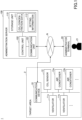
FIG. 1 is adrawing 1 illustrating an example of a configuration of an air-conditioning system according to the present embodiment. In the example ofFIG. 1 , the air-conditioning system 1 includes acommunication device 10,ventilators administration server 100 capable of communicating with thecommunication device 10 via a communication network N. The air-conditioning system 1 may also includeair conditioners administrator terminal 20. In the following description, when any of theventilators air conditioners - The ventilator 11 is a ventilator to ventilate a
target area 2. A number of ventilators 11 shown inFIG. 1 is an example, and the number of ventilators 11 may be another number which is one or greater. Thetarget area 2 is an example of a space to be ventilated by the ventilator 11. - The CO2 sensor 12 is a sensor to measure the carbon dioxide concentration (hereinafter referred to as CO2 concentration) in the
target area 2. Alternatively, the CO2 sensor 12 may be provided in thetarget area 2, or may be provided in a space through which air suctioned from thetarget area 2 passes. Alternatively, the CO2 sensor 12 may be provided in the ventilator 11, or may be provided in the air conditioner 13. - The air conditioner 13 is an air conditioner to air-condition the
target area 2. The number of air conditioners 13 shown inFIG. 1 is an example, and the number of air conditioners 13 may be another number which is one or more. In the present embodiment, the air conditioner 13 is optional and not essential. - The
communication device 10 is an information processor having a computer configuration, and is communicatively connected to, for example, the ventilator 11, the CO2 sensor 12, and the air conditioner 13. Thecommunication device 10 can communicate with, for example, theadministration server 100 or theadministrator terminal 20, etc., via the Internet or a communication network N such as a LAN (Local Area Network). Thecommunication device 10 acquires, for example, measurement data of the CO2 concentration in thetarget area 2 measured by the CO2 sensor 12, operation data of the ventilator 11, operation data of the air conditioner, and the like, and transmits them to theadministration server 100. Thecommunication device 10 transfers control data addressed to the ventilator 11, control data addressed to the air conditioner 13, and the like, received from theadministration server 100, to the ventilator 11 and the air conditioner 13. - The
administration server 100 is a system including the information processor having the computer configuration, or a plurality of computers. In the example ofFIG. 1 , theadministration server 100 includes acommunication unit 101, acontrol unit 102, astorage unit 110, and the like. - The
communication unit 101 connects theadministration server 100 to the communication network N and executes a communication process to communicate with thecommunication device 10, theadministrator terminal 20, and the like. - The
control unit 102 is a processor such as a CPU (Central Processing Unit) provided in theadministration server 100. Thecontrol unit 102 acquires the CO2 concentration in thetarget area 2 by executing a program stored in a storage medium such as thestorage unit 110, and executes a ventilation airflow rate adjustment process to adjust the rate of ventilation airflow of the ventilator 11 based on the present value of the CO2 concentration and the variation over time of the CO2 concentration. - The
storage unit 110 is realized by a storage device or the like provided in theadministration server 100, and stores various data, information, programs and the like including, for example, data of the CO2 concentration (CO2 concentration data 111) acquired by thecontrol unit 102 and various settinginformation 112 and the like. Thestorage unit 110 may be realized by another server capable of communicating with theadministration server 100 via the communication network N, or cloud storage or the like. - The
administrator terminal 20 is, for example, an information processing device such as a PC, a tablet terminal, or a smartphone used by anadministrator 21 administrating the air-conditioning system 1. Theadministrator 21 can log in to theadministration server 100 by using theadministrator terminal 20, for example, to set or change the settinginformation 112. In the present embodiment, theadministrator terminal 20 is optional and not essential. -
FIG. 2 is a drawing describing the outline of a process according to the present embodiment. The drawing is an example of variation of the CO2 concentration 201 over time in thetarget area 2, where the horizontal axis is time and the left vertical axis is the CO2 concentration [ppm]. The drawing is also an example of control of the rate ofventilation airflow 205 of the ventilator 11 by thecontrol unit 102, where the horizontal axis is time and the right vertical axis is the rate of ventilation airflow [m3/h]. - The CO2 concentration (carbon dioxide concentration) is a ratio of carbon dioxide contained in 1 m3. The CO2 concentration in outside air is approximately 400 ppm, and a standard of indoor carbon dioxide concentration is, for example, 1000 ppm or less.
- When the ventilator 11 is stopped, the CO2 concentration in the
target area 2 rises, for example, as shown by time t0 to t1 inFIG. 2 due to human respiration. The variation of the CO2 concentration 201 over time depends on the number of people in thetarget area 2. - Therefore, for example, based on the
present value 202 of the CO2 concentration 201 in thetarget area 2 and the slope (variation over time) 203 of the CO2 concentration 201, thecontrol unit 102 adjusts the rate of ventilation airflow of the ventilator 11 so that the CO2 concentration 201 becomes within therange 206 from the first predetermined value (e.g., 1000 ppm) to the second predetermined value (e.g., 800 ppm). - For example, based on the
present value 202 of the CO2 concentration 201 and theslope 203 of the CO2 concentration 201, at time t1 inFIG. 2 , thecontrol unit 102 starts the operation of the ventilator 11 when the CO2 concentration 201 is likely to exceed the first predetermined value. - Preferably, the
control unit 102 stepwise controls the rate of ventilation airflow of the ventilator 11 based on thepresent value 202 of the CO2 concentration 201 and theslope 203 of the CO2 concentration 201. For example, when the CO2 concentration 201 reaches the first predetermined value in a shorter time, thecontrol unit 102 sets the rate of ventilation airflow of the ventilator 11 to be larger. - Note that the CO2 concentration 201 of the
target area 2 varies depending on the number of people in thetarget area 2 even if the same rate of ventilation airflow is used. For example, it is assumed that the number of people in thetarget area 2 decreases and the CO2 concentration 201 in thetarget area 2 decreases after versus before time t2 inFIG. 2 . In this case, for example, at time t2 inFIG. 2 , thecontrol unit 102 decreases the rate of ventilation airflow of the ventilator 11 when, based on the present value of the CO2 concentration 201 and the slope of the CO2 concentration 201, the CO2 concentration 201 is likely to fall below the second predetermined value. In the example ofFIG. 2 , thecontrol unit 102 decreases the rate of ventilation airflow of the ventilator 11 by one step at time t2. - Similarly, the
control unit 102 increases the rate of ventilation airflow of the ventilator 11 again when, based on the present value of the CO2 concentration 201 and the slope of the CO2 concentration 201, the CO2 concentration 201 is likely to exceed the first predetermined value at time t3 inFIG. 2 . In the example ofFIG. 2 , thecontrol unit 102 increases the rate of ventilation airflow of the ventilator 11 by one step at time t3. - Similarly, the
control unit 102 decreases the rate of ventilation airflow of the ventilator 11 again when, based on the present value of the CO2 concentration 201 and the slope of the CO2 concentration 201, the CO2 concentration 201 is likely to fall below the second predetermined value at time t4 inFIG. 2 . In the example ofFIG. 2 , thecontrol unit 102 decreases the rate of ventilation airflow of the ventilator 11 by one step at time t4. - Further, for example, at time t5 in
FIG. 2 , thecontrol unit 102 stops the operation of the ventilator 11 when the CO2 concentration 201 falls below the second predetermined value based on the present value of the CO2 concentration 201 and the slope of the CO2 concentration 201 and continues to decrease. - For example, in a related art as shown in
PTL 1, the operation of the ventilator is started when the CO2 concentration exceeds a threshold value. However, in this method, for example, when the CO2 concentration exceeds the threshold value, the operation of the ventilator is started even when the CO2 concentration increases slowly and does not reach 1000 ppm. - Conversely, in the present embodiment, the operation of the ventilator 11 is started when the CO2 concentration 201 is likely to exceed 1000 ppm (an example of the first predetermined value) based on the
present value 202 of the CO2 concentration 201 and theslope 203 of the CO2 concentration 201. Therefore, according to the air-conditioning system 1 according to the present embodiment, unnecessary operation of the ventilator 11 can be suppressed. For example, the air-conditioning system 1 can delay the operation start time of the ventilator 11 until the last possible moment. - Moreover, the air-
conditioning system 1 can reduce the rate of ventilation airflow with preventing the CO2 concentration in the space to be ventilated from exceeding the predetermined value, using information of any one of: the variation over time of the CO2 concentration; the difference between the predetermined value and the CO2 concentration; or the approach time for the CO2 concentration to reach the predetermined value. The air-conditioning system 1 can reduce the rate of ventilation airflow with preventing the CO2 concentration in the space to be ventilated from exceeding the predetermined value, by changing the amount by which the rate of ventilation airflow is increased according to the approach time for the CO2 concentration to reach the predetermined concentration. - Further, in the related art, when the CO2 concentration exceeds the threshold value, the operation of the ventilator 11 is continued even if the CO2 concentration tends to decrease. Conversely, in the present embodiment, when the CO2 concentration exceeds 800 ppm (an example of the second predetermined value) but the CO2 concentration tends to decrease, the rate of ventilation airflow of the ventilator 11 is decreased or the operation of the ventilator 11 is stopped. Therefore, according to the air-
conditioning system 1 according to the present embodiment, unnecessary operation of the ventilator 11 can be further suppressed. - As described above, the air-
conditioning system 1 according to the present embodiment enables to ventilate for a minimum required time and airflow within a range in which the carbon dioxide concentration in the space to be ventilated (target area 2) does not exceed a predetermined value. - The configuration of the air-
conditioning system 1 shown inFIG. 1 is an example. For example, as shown inFIG. 3 , thecommunication device 10 may have thecommunication unit 101, thecontrol unit 102, thestorage unit 110, and the like of theadministration server 100 inFIG. 1 . Thus, the air-conditioning system 1 can adjust the rate of ventilation airflow of the ventilator 11 so that the CO2 concentration 201 falls within therange 206 of the predetermined value based on the present value of the CO2 concentration 201 in thetarget area 2 and the variation over time of the CO2 concentration 201 without depending on theadministration server 100. - Alternatively, the
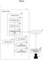
communication unit 101, thecontrol unit 102, thestorage unit 110 and the like may be provided in the ventilator 11 as shown inFIG. 4 . Thus, the air-conditioning system 1 can adjust the rate of ventilation airflow of the ventilator 11 so that the CO2 concentration 201 falls within therange 206 of the predetermined value based on the present value of the CO2 concentration 201 in thetarget area 2 and the variation over time of the CO2 concentration 201 without depending on thecommunication device 10. - Further alternatively, the
communication unit 101, thecontrol unit 102, thestorage unit 110 and the like may be distributed among theadministration server 100, thecommunication device 10, the ventilator 11 and the like. That is, thecommunication unit 101, thecontrol unit 102, thestorage unit 110 and the like may be provided in the air-conditioning system 1 and may be provided in any device in the air-conditioning system 1. - The
administration server 100, thecommunication device 10, theadministrator terminal 20 and the like have, for example, the hardware configuration of thecomputer 500 as shown inFIG. 5 . Alternatively, theadministration server 100 may be composed of a plurality ofcomputers 500. Alternatively, the ventilator 11 may have a hardware configuration of thecomputer 500. -
FIG. 5 is a drawing illustrating an example of the hardware configuration of a computer according to the present embodiment. Thecomputer 500 includes, for example, acontrol unit 102, amemory 501, astorage device 502, a communication interface (I/F) 503, anoutput device 504, aninput device 505, and adrive device 506, and other such 5- components. - The
control unit 102 is, for example, a processor such as a CPU to realize various functions by executing a predetermined program stored in a storage medium such as thestorage device 502 or thememory 501. In addition to the CPU, thecontrol unit 102 may also include a processor, for example, a GPU (Graphics Processing Unit) or a DSP (Digital Signal Processor). - The
memory 501 includes, for example, a RAM (Random Access Memory) that is a volatile memory used as a work area of thecontrol unit 102 and a ROM (Read Only Memory) that is a nonvolatile memory to store a program to start thecontrol unit 102. Thestorage device 502 is a non-volatile, large-capacity storage device to store programs such as an OS (Operating System), applications, and various types of data. - The communication I/
F 503 includes various communication interfaces to communicate with other devices. For example, the communication I/F 503 includes a NIC (Network Interface Card) to connect thecomputer 500 to the communication network N, or a wireless communication interface to communicate via wireless WAN (Wide Area Network) or wireless LAN. - The
output device 504 is, for example, such as a display, a speaker, or an LED (Light Emitting Diode) to output to the outside. Theinput device 505 is, for example, such as a touch panel, a keyboard, or a pointing device to receive an input from the outside. Theoutput device 504 and theinput device 505 may be, for example, a display input device such as a touch panel display. - The
drive device 506 is a device to connect the storage medium (recording medium) 507 to thecomputer 500. Thestorage medium 507 includes a medium to record information optically, electrically, or magnetically, for example, a CD-ROM, a flexible disk, a magneto-optical disk, or the like. Thestorage medium 507 may include a semiconductor memory for electrically recording information, for example, a ROM, a flash memory, or the like. Thebus 508 is commonly connected to the above-mentioned components and transmits, for example, an address signal, a data signal, and various control signals. - Next, a flow of process of the ventilation control method according to the present embodiment will be described.
-
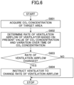
FIG. 6 is a flowchart illustrating an example of ventilation airflow rate adjustment process according to the present embodiment. This process shows an example of the ventilation airflow rate adjustment executed by the air-conditioning system 1. - In step S601, the
control unit 102 acquires the CO2 concentration (carbon dioxide concentration) of thetarget area 2. Thetarget area 2 is an example of a space to be ventilated by the ventilator 11. - Preferably, the
control unit 102 acquires the CO2 concentration data 111 of thetarget area 2 measured by the CO2 sensor 12 at a first time interval (e.g., every one minute), and uses a moving average of the CO2 concentration during a predetermined period (e.g., ten minutes before the present time) as the CO2 concentration in thetarget area 2. Thus, for example, adverse effects due to fluctuations in the CO2 concentration data 111 of thetarget area 2 can be reduced. - The moving average is an example of a process to smooth the CO2 concentration data 111. The
control unit 102 may use a method different from the moving average to smooth the CO2 concentration data 111. Further, the predetermined time interval (one minute) and the predetermined period (ten minutes) are examples, and alternatively, other values may be used. - Alternatively, the
control unit 102 may acquire the CO2 concentration data 111 of thetarget area 2 measured at a predetermined time interval from thestorage unit 110 or from thecommunication device 10. Moreover, alternatively, thecontrol unit 102 may acquire the CO2 concentration data 111 of thetarget area 2 from a cloud service that acquires and administrates measurement results from the CO2 sensor 12 or from the CO2 sensor 12. Thecontrol unit 102 determines the present value of the CO2 concentration in thetarget area 2 as the value acquired by smoothing the CO2 concentration data 111 of thetarget area 2 before the process of step S602 or the CO2 concentration data 111 of thetarget area 2 measured at a predetermined time interval by a method such as a moving average. - In step S602, the
control unit 102 determines the rate of ventilation airflow of the ventilator 11 based on the present value of the CO2 concentration in thetarget area 2 and the variation over time of the CO2 concentration in thetarget area 2. - Preferably, the
control unit 102 executes the ventilation airflow rate determination process to determine the rate of ventilation airflow of the ventilator 11 at a second time interval (e.g., every five minutes) longer than the first time interval based on the CO2 concentration in thetarget area 2 acquired at the first time interval (e.g., every one minute). The ventilation airflow rate determination process will be described later by exemplifying a plurality of embodiments. - In step S603, the
control unit 102 determines whether the newly determined rate of ventilation airflow is changed from the previous rate of ventilation airflow by the determination in step S602. If the rate of ventilation airflow is changed, thecontrol unit 102 proceeds to step S604. Conversely, if the rate of ventilation airflow is not changed, thecontrol unit 102 ends the process inFIG. 6 . - In step S604, the
control unit 102 instructs the ventilator 11 to change the rate of ventilation airflow. In the example inFIG. 1 , thecontrol unit 102 transmits control data instructing the ventilator 11 whose rate of ventilation airflow has been changed to change the rate of ventilation airflow to thecommunication device 10. In response, thecommunication device 10 transfers the control data received from theadministration server 100 to the ventilator 11, and the ventilator 11 changes the rate of ventilation airflow according to the transferred control data. The change of the rate of ventilation airflow includes starting or stopping the operation of the ventilator 11. - Subsequently, the ventilation airflow rate determination process executed by the
control unit 102 in step S602 ofFIG. 6 will be described. -
FIGS. 7A to 7C are drawings describing the ventilation airflow rate determination process according to example 1. For example, as shown inFIG. 7A , thecontrol unit 102 may determine the rate of ventilation airflow of the ventilator 11 by using thepresent value 711 of the CO2 concentration and thecorresponding information 710 in which the rate ofventilation airflow 713 of the ventilator 11 corresponding to theslope 712 of the CO2 concentration is stored in advance. - In the example of the
corresponding information 710, the rate ofventilation airflow 713 of the ventilator 11 is referred to in three steps: "0 (stop)", "L", and "H". Here, "0 (stop)" refers to that the operation of the ventilator 11 is stopped. "L" refers to that the ventilator 11 is operated weakly, and "H" refers to that the ventilator 11 is operated strongly. Further, in thecorresponding information 710, "-Y" is a threshold value of a negative slope (e.g., "-2"), and "Z" is a threshold value of a positive slope (e.g., "8"). For example, when the present value x of the CO2 concentration in thetarget area 2 is 850 ppm and the slope a of the CO2 concentration in thetarget area 2 is a value between -Y and Z (e.g., "1"), thecontrol unit 102 can determine the rate of ventilation airflow of the ventilator 11 to be "L" from thecorresponding information 710. - Here, the slope a is acquired by calculating the difference between "the present value of the CO2 concentration at the present time" and "the present value of the CO2 concentration one minute before the present time". For example, the
control unit 102 calculates the slope a by the followingformula 1.Slope a = (moving average of the CO2 concentration at the present time) - (moving average of the CO2 concentration one minute before the present time) ··· - The moving average of the CO2 concentration at the present time is calculated by averaging the CO2 concentration for ten minutes from the present time to ten minutes before the present time, for example. Similarly, the moving average of the CO2 concentration one minute before the present time is calculated by averaging the CO2 concentration for ten minutes from one minute to eleven minutes before the present time. Alternatively, the "present value" may be a moving average as shown in
formula 1, a value smoothed by another method, or the CO2 concentration data 111 measured by the CO2 sensor 12 may be used. The "present value of the CO2 concentration one minute before the present time" is an example for calculating the slope a, and a difference between the present value of the CO2 concentration predetermined time before the present time (e.g., thirty seconds, one minute, five minutes, etc.) can be used. - As another example, in the
corresponding information 720 shown inFIG. 7B , the rate ofventilation airflow 721 of the ventilator 11 is referred to in five steps of "-2", "-1", "0", "+1", and "+2". Here, "-2" refers to that the ventilation airflow rate level of the ventilator 11 is reduced by two steps, and "-1" refers to that the ventilation airflow rate level of the ventilator 11 is reduced by one step. "0" refers to that the ventilation airflow rate level of the ventilator 11 is not changed. "+1" refers to that the ventilation airflow rate level of the ventilator 11 is raised by one step, and "+2" refers to that the ventilation airflow rate level of the ventilator 11 is raised by two steps. When the ventilation airflow rate level after the change exceeds the maximum value, thecontrol unit 102 sets the ventilation airflow rate level of the ventilator 11 to the maximum value. Similarly, when the ventilation airflow rate level after the change falls below the minimum value, thecontrol unit 102 sets the ventilation airflow rate level of the ventilator 11 to the minimum value. - As another example, in the
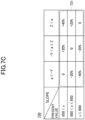
corresponding information 730 shown inFIG. 7C , the rate ofventilation airflow 731 of the ventilator 11 is referred to in five steps of "-40%", "-20%", "0", "+20%", and "+40%". Here, "-40%" refers to that the rate of ventilation airflow of the ventilator 11 is reduced by 40%, and "-20%" refers to that the rate of ventilation airflow of the ventilator 11 is reduced by 20%. "0" refers to that the rate of ventilation airflow of the ventilator 11 is not changed. "+20%" refers to that the rate of ventilation airflow of the ventilator 11 is increased by 20%, and "+40%" refers to that the rate of ventilation airflow of the ventilator 11 is increased by 40%. If the rate of ventilation airflow after the change exceeds the maximum value, thecontrol unit 102 sets the rate of ventilation airflow of the ventilator 11 to the maximum value. Similarly, if the rate of ventilation airflow after the change falls below the minimum value, thecontrol unit 102 sets the rate of ventilation airflow of the ventilator 11 to the minimum value. - The
corresponding information information 112 stored in advance in the air-conditioning system 1, for example. The setting values of thecorresponding information administrator 21 or the like using theadministrator terminal 20. -
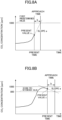
FIGS. 8A, 8B , and9 are drawings describing the ventilation airflow rate determination process according to example 2. For example, as shown inFIG. 8A , when the slope a of the CO2 concentration is "a > 0", thecontrol unit 102 may determine the rate of ventilation airflow of the ventilator 11 based on the approach time b for the CO2 concentration in thetarget area 2 to reach the first predetermined value (e.g., 1000 ppm). - The slope a of the CO2 concentration can be calculated, for example, by subtracting the moving average of the CO2 concentration one minute before the present time from the moving average of the CO2 concentration at the present time. The approach time b for the CO2 concentration in the
target area 2 to reach the first predetermined value can be calculated, for example, by the followingformula 2 from the present CO2 concentration x and the slope a of the CO2 concentration.
- For example, when the slope a of the CO2 concentration is "a > 0", the
control unit 102 controls the rate of ventilation airflow of the ventilator 11 based on the approach time b as follows. - When the approach time b is less than a predetermined first time T1 (e.g., twenty minutes) and larger than or equal to a predetermined second time T2 (e.g., ten minutes), the
control unit 102 raises the ventilation airflow rate level of the ventilator 11 by one step. - When the approach time b is less than the second time T2 and larger than or equal to a predetermined third time T3 (e.g., five minutes), the
control unit 102 raises the ventilation airflow rate level of the ventilator 11 by two steps. - When the approach time is less than the third time T3, the
control unit 102 raises the ventilation airflow rate level of the ventilator 11 by three steps. When the ventilation airflow rate level of the ventilator 11 exceeds the maximum level by the above control, thecontrol unit 102 sets the ventilation airflow rate level of the ventilator 11 to the maximum level. - Here, as an example, the
control unit 102 controls the rate of ventilation airflow of the ventilator 11 every five minutes, and the first time T1 is set to twenty minutes, or five minutes times four. The second time T2 is set to ten minutes, or five minutes times two, and the third time T3 is set to 5 minutes. However, the first time T1, the second time T2, and the third time T3 are examples, and alternatively, may be other values. - Thus, when the CO2 concentration in the
target area 2 reaches the first predetermined value in a shorter time, thecontrol unit 102 preferably sets the rate of ventilation airflow of the ventilator 11 to a larger value. - Preferably, when the CO2 concentration in the
target area 2 exceeds a predetermined threshold value (e.g., 700 ppm), thecontrol unit 102 executes the process to increase the rate of ventilation airflow of the ventilator 11. Alternatively, when the CO2 concentration in the target area is less than a predetermined threshold value, thecontrol unit 102 stops the operation of the ventilator 11. - Further, for example, as shown in
FIG. 8B , when the slope a of the CO2 concentration is "a ≤ 0", thecontrol unit 102 may determine the rate of ventilation airflow of the ventilator 11 based on the approach time b for the CO2 concentration in thetarget area 2 to reach a second predetermined value (e.g., 800 ppm). - For example, when the slope a of the CO2 concentration is "a ≤ 0", the
control unit 102 controls the rate of ventilation airflow of the ventilator 11 based on the approach time b as follows. - When the approach time b is less than a predetermined fourth time T4 (e.g., twenty minutes) and larger than or equal to a predetermined fifth time T5 (e.g., ten minutes), the
control unit 102 decreases the ventilation airflow rate level of the ventilator 11 by one step. - When the approach time b is less than the fifth time T5 and larger than or equal to a predetermined sixth time T6 (e.g., five minutes), the
control unit 102 lowers the ventilation airflow rate level of the ventilator 11 by two steps. - When the approach time is less than the sixth time T6, the
control unit 102 lowers the ventilation airflow rate level of the ventilator 11 by three steps. When the ventilation airflow rate level of the ventilator 11 falls below the minimum level by the above control, thecontrol unit 102 sets the ventilation airflow rate level of the ventilator 11 to the minimum level or stops the operation of the ventilator 11. - Here, as an example, the fourth time T4 is twenty minutes, the fifth time T5 is ten minutes, and the sixth time is five minutes. However, the fourth time T4, the fifth time T5, and the sixth time T6 are examples and may be other values.
- Thus, when the CO2 concentration in the
target area 2 reaches the second predetermined value in a shorter time, thecontrol unit 102 preferably sets the rate of ventilation airflow of the ventilator 11 to a smaller value. - As another example, for example, as shown in
FIG. 9 , when the inclination a of the CO2 concentration is "a ≤ 0", thecontrol unit 102 may determine the rate of ventilation airflow of the ventilator 11 based on the inclination a of the CO2 concentration in thetarget area 2. - For example, when the inclination a of the CO2 concentration is "a ≤ 0", the
control unit 102 controls the rate of ventilation airflow of the ventilator 11 based on the inclination a as follows. - When the slope b is less than a predetermined first inclination Y1 (e.g., -2 = -20 ppm / 10 min) and larger than or equal to a predetermined second inclination Y2 (e.g., -5 = -50 ppm / 10 min), the
control unit 102 decreases the ventilation airflow rate level of the ventilator 11 by one step. - When the slope b is less than a second inclination Y2, or when the CO2 concentration in the
target area 2 is less than a predetermined threshold value (e.g., 700 ppm), thecontrol unit 102 decreases the ventilation airflow rate level of the ventilator 11 by two steps. - When the ventilation airflow rate level of the ventilator 11 falls below the minimum level by the above control, the
control unit 102 sets the ventilation airflow rate level of the ventilator 11 to the minimum level or stops the operation of the ventilator 11. - Preferably, when the CO2 concentration in the
target area 2 is equal to or less than the first predetermined value (e.g., 1000 ppm), thecontrol unit 102 executes the process to reduce the rate of ventilation airflow of the ventilator 11. -
FIG. 10 is adrawing 1 describing the ventilation airflow rate determination process according to example 3. Thecontrol unit 102 may adjust the rate of ventilation airflow of the ventilator 11 using, for example, a difference c between the present value of the CO2 concentration in thetarget area 2 and the predetermined value of the CO2 concentration (e.g., 1000 ppm) and a slope (variation over time) a of the CO2 concentration. -
FIGS. 11A-C aredrawings 2 to 4 describing a ventilation airflow rate determination process according to example 3. For example, as shown inFIG. 11A , thecontrol unit 102 may determine the rate of ventilation airflow of the ventilator 11 usingcorresponding information 1110 in which the rate ofventilation airflow 1113 of the ventilator 11 corresponding to thedifference 1111 between the predetermined value of the CO2 concentration and the present value of the CO2 concentration and theslope 1112 of the CO2 concentration are stored in advance. - In the example of
corresponding information 1110, the rate ofventilation airflow 1113 of the ventilator 11 is referred to in three steps of "0 (stop)", "L", and "H". Here, "0 (stop)" refers to that the operation of the ventilator 11 is stopped. "L" refers to that the ventilator 11 is operated weakly, and "H" indicates that the ventilator 11 is operated strongly. Further, in thecorresponding information 1110, "-Y" refers to a threshold value of a negative slope (e.g., "-2"), and "Z" refers to a threshold value of a positive slope (e.g., "8"). For example, if the difference c between the predetermined value of the CO2 concentration and the present value of the CO2 concentration is 100, and the slope a of the CO2 concentration is a value between Y and Z (e.g., "5"), thecontrol unit 102 can determine the rate of ventilation airflow of the ventilator 11 to be "L" from thecorresponding information 1110. - As another example, in the
corresponding information 1120 shown inFIG. 11B , the rate ofventilation airflow 1121 of the ventilator 11 is referred to in five steps of "-2", "-1", "0", "+1", and "+2". Here, "-2" refers to that the ventilation airflow rate level of the ventilator 11 is decreased by two steps, and "-1" refers to that the ventilation airflow rate level of the ventilator 11 is decreased by one step. "0" refers to that the ventilation airflow rate level of the ventilator 11 is not changed. "+1" refers to that the ventilation airflow rate level of the ventilator 11 is increased by one step, and "+2" refers to that the ventilation airflow rate level of the ventilator 11 is increased by two steps. When the ventilation airflow rate level after the change exceeds the maximum value, thecontrol unit 102 sets the ventilation airflow rate level of the ventilator 11 to the maximum value. Similarly, if the ventilation airflow rate level after the change falls below the minimum value, thecontrol unit 102 sets the ventilation airflow rate level of the ventilator 11 to the minimum value or stops the operation of the ventilator 11. - As another example, in the
corresponding information 1130 shown inFIG. 11C , the rate ofventilation airflow 1131 of the ventilator 11 is referred to in five steps of "-40%", "-20%", "0", "+20%", and "+40%". Here, "-40%" refers to that the rate of ventilation airflow of the ventilator 11 is reduced by 40%, and "-20%" refers to that the rate of ventilation airflow of the ventilator 11 is reduced by 20%. "0" refers to that the rate of ventilation airflow of the ventilator 11 is not changed. "+20%" refers to that the rate of ventilation airflow of the ventilator 11 is increased by 20%, and "+40%" refers to that the rate of ventilation airflow of the ventilator 11 is increased by 40%. When the rate of ventilation airflow after the change exceeds the maximum value, thecontrol unit 102 sets the rate of ventilation airflow of the ventilator 11 to the maximum value. Similarly, when the rate of ventilation airflow after the change falls below the minimum value, thecontrol unit 102 sets the rate of ventilation airflow of the ventilator 11 to the minimum value or stops the operation of the ventilator 11. - Such
corresponding information information 112 stored in advance in the air-conditioning system 1, for example. Theadministrator 21 or the like may change the set values of thecorresponding information administrator terminal 20. - Alternatively, the
control unit 102 may determine the rate of ventilation airflow of the ventilator 11 without depending on thecorresponding information - For example, if the inclination a of the CO2 concentration is "a > 0", the
control unit 102 may control the rate of ventilation airflow of the ventilator 11 based on the difference c between the predetermined value of the CO2 concentration and the present value of the CO2 concentration as follows. - When the difference c between the predetermined value of the CO2 concentration and the present value of the CO2 concentration satisfies c < T7 × a, the
control unit 102 raises the ventilation airflow rate level of the ventilator 11 by one step. Here, T7 is a preset seventh time T7 (e.g., twenty minutes), and a is the inclination a of the CO2 concentration. - When the difference c between the predetermined value of the CO2 concentration and the present value of the CO2 concentration satisfies c < T8 × a, the
control unit 102 raises the ventilation airflow rate level of the ventilator 11 by two steps. Here, T8 is the preset eighth time T8 (e.g., ten minutes). When the ventilation airflow rate level of the ventilator 11 exceeds the maximum level by the above control, thecontrol unit 102 sets the ventilation airflow rate level of the ventilator 11 to the maximum level. - If the inclination a of the CO2 concentration is "a ≤ 0", the
control unit 102 may control the rate of ventilation airflow of the ventilator 11 based on the inclination a of the CO2 concentration as follows. - When the inclination a of the CO2 concentration satisfies a < A1, the
control unit 102 decreases the rate of ventilation airflow of the ventilator 11 by one step. Here, A1 is a predetermined first inclination (e.g., -5). - When the inclination a of the CO2 concentration satisfies a < A2, the
control unit 102 decreases the rate of ventilation airflow of the ventilator 11 by two steps. Here, A2 is a predetermined second inclination (e.g., -10). When the ventilation airflow rate level of the ventilator 11 falls below the minimum level by the above control, thecontrol unit 102 sets the ventilation airflow rate level of the ventilator 11 to the minimum level or stops the operation of the ventilator 11. - The
control unit 102 can determine the rate of ventilation airflow of the ventilator 11 based on the present value of the CO2 concentration in thetarget area 2 and the variation over time of the CO2 concentration, for example, according to the above-described examples 1-3. - In example 4, an example of a process in which the air-
conditioning system 1 includes a plurality of ventilators 11 and thecontrol unit 102 adjusts the rate of ventilation airflow of the plurality of ventilators 11 based on the present value of the CO2 concentration in thetarget area 2 and the variation over time of the CO2 concentration in thetarget area 2 will be described. -
FIG. 12 is aflowchart 1 illustrating an example of a ventilation airflow rate adjustment process according to example 4. Here, a detailed description of the process similar to the ventilation airflow rate adjustment process described with reference toFIG. 6 is omitted. - In step S1201, the
control unit 102 acquires the CO2 concentration (carbon dioxide concentration) of thetarget area 2. Here, for example, as shown inFIG. 13 , it is assumed that one CO2 sensor 12 is installed in thetarget area 2. The CO2 sensor 12 is installed, for example, in a place where there are many people in thetarget area 2, and thecontrol unit 102 adjusts the rate of ventilation airflow of theventilator 11b close to the CO2 sensor. - Preferably, the
control unit 102 acquires the CO2 concentration data 111 of thetarget area 2 measured by the CO2 sensor 12 at a first time interval (e.g., every one minute), and uses a moving average of the CO2 concentration during a predetermined period (e.g., ten minutes before the present time) as the CO2 concentration in thetarget area 2. The moving average is an example of smoothing the CO2 concentration data 111. Thecontrol unit 102 may use a method other than the moving average to smooth theconcentration data 111. - In step S1202, the
control unit 102 determines the rate of ventilation airflow of theventilator 11b based on the present value of the CO2 concentration in thetarget area 2 and the variation over time of the CO2 concentration in thetarget area 2. - Preferably, the
control unit 102 executes the ventilation airflow rate determination process to determine the rate of ventilation airflow of the ventilator 11 at a second time interval (e.g., every five minutes) longer than the first time interval based on the CO2 concentration in thetarget area 2 acquired at the first time interval (e.g., every one minute). For the ventilation airflow rate determination process, for example, the process described in example 1-3 can be applied. - In step S1203, the
control unit 102 determines whether the rate of ventilation airflow of theventilator 11b is changed from the previous rate of ventilation airflow. If the rate of ventilation airflow is changed, thecontrol unit 102 proceeds to step S1204. Conversely, if the rate of ventilation airflow is not changed, thecontrol unit 102 ends the process ofFIG. 12 . - In step S1204, the
control unit 102 instructs theventilator 11b to change the rate of ventilation airflow. In the example ofFIG. 1 , thecontrol unit 102 transmits control data instructing theventilator 11b whose rate of ventilation airflow has been changed to change the rate of ventilation airflow to thecommunication device 10. In response, thecommunication device 10 transfers the control data received from theadministration server 100 to theventilator 11b, and theventilator 11b changes the rate of ventilation airflow according to the transferred control data. - When two or more CO2 sensors 12 are installed in the
target area 2, thecontrol unit 102 may execute the same process for the respective ventilators 11 close to the respective CO2 sensors 12. - The process shown in
FIG. 12 is an example. Instead of the process shown inFIG. 12 , thecontrol unit 102 may execute the ventilation airflow rate adjustment process as shown inFIG. 14 , for example. -
FIG. 14 is aflowchart 2 illustrating an example of a ventilation airflow rate adjustment process according to example 4. Here, a detailed description of the process similar to the ventilation airflow rate adjustment process described with reference toFIGS. 6 and12 is omitted. - In step S1401, the
control unit 102 acquires the CO2 concentration (carbon dioxide concentration) of thetarget area 2. Here, for example, as shown inFIG. 13 , one CO2 sensor 12 is installed in thetarget area 2, and thecontrol unit 102 adjusts the rate of ventilation airflows of theventilators target area 2. - Preferably, the
control unit 102 acquires the CO2 concentration data 111 of thetarget area 2 measured by the CO2 sensor 12 at a first time interval (e.g., every one minute), and sets the moving average of the CO2 concentration during a predetermined period (e.g., ten minutes before the present time) as the CO2 concentration in thetarget area 2. - In step S1402, the
control unit 102 determines the rate of ventilation airflows of theventilators target area 2 and the variation over time of the CO2 concentration in thetarget area 2. - Preferably, the
control unit 102 executes the determination process of the rate of ventilation airflows to determine the rate of ventilation airflows of theventilators target area 2 acquired at the first time interval (e.g., every one minute). For example, thecontrol unit 102 may control theventilators - As another example, the
ventilators ventilators control unit 102 may apply the process described in example 1-3 to determine the rate of ventilation airflow of theventilator 11b close to the CO2 sensor 12, and determine the rate of ventilation airflows of theventilators ventilator 11b and the weights of theventilators - In step S1403, the
control unit 102 determines whether the rate of ventilation airflows of theventilators control unit 102 proceeds to step S1404. Conversely, if the rate of ventilation airflows are not changed, thecontrol unit 102 ends the process ofFIG. 12 . - In step S1404, the
control unit 102 instructs the ventilators 11 of theventilators - When two or more CO2 sensors 12 are installed in the
target area 2, the ventilators 11 corresponding to the CO2 sensors 12 are grouped in advance for the respective CO2 sensors 12, and thecontrol unit 102 may execute the process ofFIG. 14 for the respective groups. -
FIG. 15 is a drawing describing an effect of an air-conditioning system 1 according to the present embodiment. In thegraph 1500 ofFIG. 15 , the horizontal axis indicates the number of persons in thetarget area 2, and the vertical axis indicates the rate of ventilation airflow. The rate of ventilation airflow is the total of the rate of ventilation airflows of the plurality of ventilators 11, thelevel 4 corresponds to the total of the rate of ventilation airflows when the rate of ventilation airflows of all the ventilators 11 are "strong", and thelevel 3 corresponds to the total of the rate of ventilation airflows when the rate of ventilation airflows of all the ventilators 11 are "weak". Thelevel 2 corresponds to the total of the rate of ventilation airflows when the ventilators 11 of "weak" and the ventilators 11 of "stop" are both present, and thelevel 1 corresponds to the total of the rate of ventilation airflows when all the ventilators 11 are "stop". - In the
graph 1500, the state in which the number of persons is (1) is assumed to be a state in which there are persons close to the capacity in thetarget area 2, the CO2 concentration in thetarget area 2 is near 1000 ppm at the rate ofventilation airflow level 4, and the CO2 concentration in thetarget area 2 exceeds 1000 ppm at the rate ofventilation airflow level 3. The state in which the number of persons is (2) is assumed to be a state in which the number of persons in thetarget area 2 is less than the capacity, the CO2 concentration in thetarget area 2 is approximately 800 ppm to 1000 ppm at the rate ofventilation airflow level 4, and the CO2 concentration in thetarget area 2 exceeds 850 ppm to 1000 ppm or less at the rate ofventilation airflow level 3. The state in which the number of persons is (3) is assumed to be a state in which the number of persons in thetarget area 2 is small and the CO2 concentration in thetarget area 2 is 850 ppm or less atlevel 3 of the rate of ventilation airflow, and the CO2 concentration in thetarget area 2 is over 1000 ppm atlevel 1. The state in which the number of persons is (4) is assumed to be a state in which the number of persons in thetarget area 2 is even smaller and the CO2 concentration in thetarget area 2 is over 700 ppm to 1000 ppm atlevel 1 of the rate of ventilation airflow. - The
first line 1501 refers to the relation between the number of persons whose CO2 concentration is 1000 ppm and the rate of ventilation airflow. Thesecond line 1502 refers to the relation between the number of persons whose CO2 concentration is 850 ppm and the rate of ventilation airflow. Thethird line 1503 refers to the relation between the number of persons whose CO2 concentration is 700 ppm and the rate of ventilation airflow. - Further, the line of the
threshold control 1511 refers to a control in which the rate of ventilation airflow is set tolevel 3 when the CO2 concentration in thetarget area 2 is 700 ppm to 850 ppm, the rate of ventilation airflow is set tolevel 4 when over 850 ppm, and the rate of ventilation airflow is set tolevel 1 when 700 ppm or less. The line of thepresent embodiment 1511 refers to the control of the rate of ventilation airflow of all the ventilators 11 according to the present embodiment. - In this state of (1), the
threshold control 1511 and thepresent embodiment 1512 both set the rate of ventilation airflow to level 4 (the rate of ventilation airflows of all the ventilators 11 are "strong"). - When the number of people in the
target area 2 decreases and the state shifts from the state (1) to the state (2), thepresent embodiment 1512 switches the rate of ventilation airflow fromlevel 4 to level 3 (the rate of ventilation airflows of all the ventilators 11 are "weak") based on the present value and variation over time of the CO2 concentration. Conversely, in thethreshold control 1511, ventilation is continued at the rate of ventilation airflow oflevel 4 until the CO2 concentration in thetarget area 2 becomes 850 ppm or less. - When the number of people in the
target area 2 further decreases, thepresent embodiment 1512 can further reduce the rate of ventilation airflow by one level based on the present value and variation over time of the CO2 concentration. For example, in the example ofFIG. 15 , the air-conditioning system 1 changes the rate of ventilation airflow fromlevel 3 to level 2 (the ventilators 11 of "weak" rate of ventilation airflow and the ventilators 11 of "stop" rate of ventilation airflow are both present). - When the number of people in the
target area 2 further decreases and the state (2) shifts to the state (3), in thethreshold control 1511, the rate of ventilation airflows of all the ventilators 11 are switched fromlevel 4 tolevel 3. - When the number of people in the
target area 2 further decreases and the state (3) shifts to the state (4), thepresent embodiment 1512 can change the rate of ventilation airflows of all the ventilators 11 to level 1 (stop the operation of all the ventilators 11) based on the present value of the CO2 concentration and the variation over time. Conversely, in thethreshold control 1511, the ventilation is continued atlevel 3 until the CO2 concentration in thetarget area 2 becomes 700 ppm or less. - Thus, the present embodiment enables to ventilate for a minimum time and airflow within a range in which the carbon dioxide concentration in the space to be ventilated does not exceed a predetermined value. Therefore, according to the present embodiment, the rate of ventilation airflow of the air-
conditioning system 1 can be reduced. By reducing the rate of ventilation airflow, the load on the air conditioner 13 of the air-conditioning system 1 can also be reduced. - The air-
conditioning system 1 according to the present disclosure is an air-conditioning system 1 including a ventilator 11 and acontrol unit 102 for controlling the ventilator 11, wherein thecontrol unit 102 acquires the CO2 concentration (carbon dioxide concentration) of atarget area 2 to be ventilated by the ventilator 11, and adjusts the rate of ventilation airflow of the ventilator 11 based on the present value of the CO2 concentration and the variation over time of the CO2 concentration. - According to the air-
conditioning system 1, the air-conditioning system 1 including the ventilator 11 enables to ventilate for a minimum amount of time and airflow within a range in which the CO2 concentration in thetarget area 2 to be ventilated does not exceed a predetermined value. - Preferably, the
control unit 102 adjusts the rate of ventilation airflow of the ventilator 11 using the present value of the CO2 concentration in thetarget area 2, the predetermined value that is a predetermined CO2 concentration, and the variation over time of the CO2 concentration in thetarget area 2. Thus, thecontrol unit 102 can reduce the rate of ventilation airflow with preventing the CO2 concentration in thetarget area 2 from exceeding the predetermined value, using information of the variation over time of the CO2 concentration in thetarget area 2. - Preferably, the
control unit 102 adjusts the rate of ventilation airflow of the ventilator 11 using the difference between the present value of the CO2 concentration and the predetermined value that is a predetermined CO2 concentration in thetarget area 2, and a variation over time of the CO2 concentration in thetarget area 2. Thus, thecontrol unit 102 can reduce the rate of ventilation airflow with preventing the CO2 concentration in thetarget area 2 from exceeding the predetermined value, using information of the difference between the present value of the CO2 concentration in thetarget area 2 and the predetermined value of the CO2 concentration. - Preferably, the
control unit 102 calculates the approach time for the CO2 concentration in thetarget area 2 to reach a predetermined value that is a predetermined CO2 concentration from the present value of the CO2 concentration in thetarget area 2 and the variation over time of the CO2 concentration in thetarget area 2, and adjusts the rate of ventilation airflow of the ventilator 11 based on the calculated approach time. Thus, thecontrol unit 102 can reduce the rate of ventilation airflow with preventing the CO2 concentration in thetarget area 2 from exceeding the predetermined value, using information of the approach time for the CO2 concentration in thetarget area 2 to reach the predetermined value that is the predetermined CO2 concentration. - Preferably, when the present value of the CO2 concentration in the
target area 2 is smaller than the first predetermined value of the CO2 concentration determined in advance and the approach time for the CO2 concentration in thetarget area 2 to reach the first predetermined value is within a first time, thecontrol unit 102 increases the rate of ventilation airflow of the ventilator 11 by a first increase. - Preferably, when the approach time is within a second time, which is shorter than the first time, the
control unit 102 increases the rate of ventilation airflow of the ventilator 11 by a second decrease, which is larger than the first increase. Thus, the air-conditioning system 1 can reduce the rate of ventilation airflow with preventing the CO2 concentration in thetarget area 2 from exceeding the first predetermined value, even when the CO2 concentration in thetarget area 2 increases rapidly. - Preferably, when the present value of the CO2 concentration in the
target area 2 is larger than the second predetermined value of the CO2 concentration, and the time required for the CO2 concentration in thetarget area 2 to reach the second predetermined value is within the third time, thecontrol unit 102 lowers the rate of ventilation airflow of the ventilator 11 by a first decreasing amount. - Preferably, when the approach time for the CO2 concentration in the
target area 2 to reach the second predetermined value is within a fourth time, which is shorter than the third time, thecontrol unit 102 lowers the rate of ventilation airflow of the ventilator 11 by a second decrease, which is larger than the first decrease, or stops the operation of the ventilator 11. Thus, the air-conditioning system 1 can reduce the rate of ventilation airflow when the CO2 concentration in thetarget area 2 decreases rapidly. - Preferably, the
control unit 102 stops the operation of the ventilator 11 when the present value of the CO2 concentration in thetarget area 2 is equal to or less than a predetermined threshold value of the CO2 concentration. - Preferably, the air-
conditioning system 1 includes a plurality of ventilators 11, and thecontrol unit 102 adjusts the rate of ventilation airflows of the plurality of ventilators based on the present value of the carbon dioxide concentration and the variation over time of the carbon dioxide concentration. - Preferably, the
control unit 102 determines the rate of ventilation airflow of the ventilator 11 in a time interval longer than a time interval for measuring the CO2 concentration in thetarget area 2. - Preferably, the
control unit 102 smooths the acquired CO2 concentration in thetarget area 2 and calculates the variation over time of the CO2 concentration in thetarget area 2. Thus, the air-conditioning system 1 can reduce adverse effects caused by variations in the data of the CO2 concentration and the carbon dioxide concentration in thetarget area 2. - Preferably, the air-
conditioning system 1 includes a ventilator 11 and acommunication device 10 capable of communicating with the ventilator 11, and thecommunication device 10 includes acontrol unit 102. - In the ventilation control method according to the present disclosure, in an air-
conditioning system 1 including a ventilator 11 and acontrol unit 102 to control the ventilator 11, thecontrol unit 102 acquires the CO2 concentration intarget area 2 to be ventilated by the ventilator 11, and adjusts the rate of ventilation airflow of the ventilator 11 based on the present value of the CO2 concentration in thetarget area 2 and the variation over time of the CO2 concentration in thetarget area 2. - Further, the present invention is not limited to these embodiments described above, but various variations and modifications may be made without departing from the claims and scope of the present invention.
- The present application is based on and claims priority to
Japanese patent application No. 2023-115680 filed on July 14, 2023 -
- 1
- air-conditioning system
- 2
- target area (space to be ventilated)
- 10
- communication device
- 11, 11a, 11b, 11c
- ventilator
- 12
- CO2 sensor
- 100
- administration server
- 102
- control unit
- 500
- computer
- N
- communication network
Claims (14)
- An air-conditioning system comprising:a ventilator; anda control unit configured to control the ventilator,wherein the control unit is configured to:acquire a carbon dioxide concentration in a space to be ventilated by the ventilator;and adjust a rate of ventilation airflow of the ventilator based on a present value of the carbon dioxide concentration, and a variation over time of the carbon dioxide concentration.
- The air-conditioning system according to claim 1, wherein the control unit is configured to adjust the rate of ventilation airflow of the ventilator using the present value of the carbon dioxide concentration, a predetermined value that is a predetermined carbon dioxide concentration, and the variation over time of the carbon dioxide concentration.
- The air-conditioning system according to claim 1, wherein the control unit is configured to adjust the rate of ventilation airflow of the ventilator using a difference between the present value of the carbon dioxide concentration and a predetermined value of the carbon dioxide concentration, and the variation over time of the carbon dioxide concentration.
- The air-conditioning system according to claim 1, wherein the control unit is configured to:calculate an approach time for the carbon dioxide concentration to reach a predetermined value that is a predetermined carbon dioxide concentration based on the present value of the carbon dioxide concentration and the variation over time of the carbon dioxide concentration; andadjust the rate of ventilation airflow of the ventilator based on the approach time.
- The air-conditioning system according to claim 1, wherein the control unit is configured to raise the rate of ventilation airflow of the ventilator by a first increase, when the present value of the carbon dioxide concentration is smaller than a first predetermined value of the carbon dioxide concentration and an approach time for the carbon dioxide concentration to reach the first predetermined value is within a first time.
- The air-conditioning system according to claim 5, wherein the control unit is configured to raise the rate of ventilation airflow of the ventilator by a second increase larger than the first increase, when the approach time is within a second time shorter than the first time.
- The air-conditioning system according to claim 1, wherein the control unit is configured to reduce the rate of ventilation airflow of the ventilator by a first decrease, when the present value of the carbon dioxide concentration is larger than a second predetermined value of the carbon dioxide concentration and an approach time for the carbon dioxide concentration to reach the second predetermined value is within a third time.
- The air-conditioning system according to claim 7, wherein the control unit is configured to reduce the rate of ventilation airflow of the ventilator by a second decrease larger than the first decrease, or to stop an operation of the ventilator, when the approach time is within a fourth time shorter than the third time.
- The air-conditioning system according to any one of claims 1 to 8, wherein the control unit is configured to stop the operation of the ventilator, when the present value of the carbon dioxide concentration is a predetermined threshold or less.
- The air-conditioning system according to any one of claims 1 to 8, wherein:the air-conditioning system includes a plurality of ventilators; andthe control unit is configured to adjust the rate of ventilation airflow of the plurality of ventilators based on the present value of the carbon dioxide concentration, and the variation over time of the carbon dioxide concentration.
- The air-conditioning system according to any one of claims 1 to 8, wherein the control unit is configured to determine the rate of ventilation airflow in a time interval longer than a time interval to measure the carbon dioxide concentration.
- The air-conditioning system according to any one of claims 1 to 8, wherein the control unit is configured to calculate the variation over time of the carbon dioxide concentration by smoothing an acquired carbon dioxide concentration.
- The air-conditioning system according to any one of claims 1 to 8,wherein the air-conditioning system includes the ventilator, and a communication device communicable with the ventilator, andwherein the communication device includes the control unit.
- A ventilation control method in an air-conditioning system includes a ventilator and a control unit configured to control the ventilator,
wherein the control unit is configured to:acquire a carbon dioxide concentration in a space to be ventilated by the ventilator; andadjust a rate of ventilation airflow of the ventilator based on a present value of the carbon dioxide concentration and a variation over time of the carbon dioxide concentration.
Applications Claiming Priority (2)
| Application Number | Priority Date | Filing Date | Title |
|---|---|---|---|
| JP2023115680 | 2023-07-14 | ||
| PCT/JP2024/025055 WO2025018255A1 (en) | 2023-07-14 | 2024-07-11 | Air conditioning system and ventilation control method |
Publications (2)
| Publication Number | Publication Date |
|---|---|
| EP4521034A1 true EP4521034A1 (en) | 2025-03-12 |
| EP4521034A4 EP4521034A4 (en) | 2025-09-03 |
Family
ID=93289126
Family Applications (1)
| Application Number | Title | Priority Date | Filing Date |
|---|---|---|---|
| EP24787397.9A Pending EP4521034A4 (en) | 2023-07-14 | 2024-07-11 | AIR CONDITIONING AND VENTILATION CONTROL METHODS |
Country Status (4)
| Country | Link |
|---|---|
| EP (1) | EP4521034A4 (en) |
| JP (1) | JP7623622B1 (en) |
| CN (1) | CN121399418B (en) |
| WO (1) | WO2025018255A1 (en) |
Family Cites Families (16)
| Publication number | Priority date | Publication date | Assignee | Title |
|---|---|---|---|---|
| JP2000088320A (en) * | 1998-09-10 | 2000-03-31 | Mitsubishi Electric Building Techno Service Co Ltd | Automatic ventilation system |
| JP3834208B2 (en) * | 2001-03-12 | 2006-10-18 | 矢崎総業株式会社 | Ventilation support device |
| CN100432561C (en) * | 2004-07-08 | 2008-11-12 | 乐金电子(天津)电器有限公司 | Air volume control method of ventilation system |
| JP5868740B2 (en) * | 2012-03-08 | 2016-02-24 | 株式会社東芝 | Air conditioning control device and air conditioning control method |
| CN106196416B (en) * | 2014-08-15 | 2019-07-23 | 台达电子工业股份有限公司 | Intelligent air conditioner control system and intelligent control method thereof |
| US10520214B2 (en) * | 2015-07-01 | 2019-12-31 | Mitsubishi Electric Corporation | Air-conditioning system control apparatus and air-conditioning system |
| JP6414240B2 (en) * | 2017-01-26 | 2018-10-31 | ダイキン工業株式会社 | Ventilation system |
| JP2020106188A (en) * | 2018-12-27 | 2020-07-09 | パナソニックIpマネジメント株式会社 | Ventilation |
| US11879658B2 (en) * | 2019-01-10 | 2024-01-23 | Mitsubishi Electric Corporation | Air-conditioning ventilation system |
| US20220316742A1 (en) * | 2019-10-01 | 2022-10-06 | Mitsubishi Electric Corporation | Ventilation apparatus, ventilation system, and ventilation control method |
| JP2021143810A (en) * | 2020-03-13 | 2021-09-24 | 東京瓦斯株式会社 | Air conditioning system |
| CN111720948A (en) * | 2020-06-12 | 2020-09-29 | 珠海格力电器股份有限公司 | Control method and device of fresh air conditioner |
| JP2022157502A (en) * | 2021-03-31 | 2022-10-14 | ダイキン工業株式会社 | Machine learning device, ventilation control device, and ventilation control method |
| JP7367134B2 (en) * | 2021-08-23 | 2023-10-23 | 旭化成エレクトロニクス株式会社 | Carbon dioxide concentration prediction system, carbon dioxide concentration prediction method, and carbon dioxide concentration prediction program |
| CN114110988A (en) * | 2021-11-17 | 2022-03-01 | 珠海格力电器股份有限公司 | Control method for automatic ventilation of fresh air conditioner and fresh air conditioner |
| JP7833299B2 (en) | 2022-02-08 | 2026-03-19 | キヤノン電子株式会社 | Star tracker and star position calculation method |
-
2024
- 2024-06-28 JP JP2024104795A patent/JP7623622B1/en active Active
- 2024-07-11 WO PCT/JP2024/025055 patent/WO2025018255A1/en not_active Ceased
- 2024-07-11 EP EP24787397.9A patent/EP4521034A4/en active Pending
- 2024-07-11 CN CN202480042788.4A patent/CN121399418B/en active Active
Also Published As
| Publication number | Publication date |
|---|---|
| EP4521034A4 (en) | 2025-09-03 |
| CN121399418A (en) | 2026-01-23 |
| WO2025018255A1 (en) | 2025-01-23 |
| JP7623622B1 (en) | 2025-01-29 |
| JP2025018955A (en) | 2025-02-06 |
| CN121399418B (en) | 2026-05-08 |
Similar Documents
| Publication | Publication Date | Title |
|---|---|---|
| US7155318B2 (en) | Air conditioning unit control to reduce moisture varying operations | |
| WO2023197694A1 (en) | Variable-frequency control method and apparatus for air conditioner, and air conditioner and storage medium | |
| CN101975434B (en) | Variable static pressure control method for variable air volume air conditioning system | |
| US20220316742A1 (en) | Ventilation apparatus, ventilation system, and ventilation control method | |
| JP6179321B2 (en) | Storage management device, control method, and control program | |
| CN110196767A (en) | Service resource control method, device, equipment and storage medium | |
| US10037162B2 (en) | Storage management device, storage management method, and computer-readable recording medium | |
| US10054328B2 (en) | Operational conditioning based on environmental components | |
| WO2020199672A1 (en) | Air conditioner, control method and control device therefor, storage medium and processor | |
| CN111854121A (en) | Humidity detection method and device, humidification control method and device, and air conditioning system | |
| US11466885B2 (en) | Air-conditioning control device, air-conditioning system, and air-conditioning control method | |
| CN107655169A (en) | Air treatment method, device and computer readable storage medium | |
| CN113849271A (en) | Cloud desktop display method, device, device, system and storage medium | |
| CN110057043B (en) | Humidification control method of air conditioner, air conditioner and storage medium | |
| CN121399418B (en) | Air conditioning system and ventilation control method | |
| US7873759B2 (en) | Information processing system and method of allocating I/O to paths in same | |
| US20160142335A1 (en) | Storage management device, storage management method, and computer-readable recording medium | |
| EP3926778A1 (en) | Target electric power calculation device, target electric power calculation method, and target electric power calculation program | |
| CN108759004B (en) | Air conditioner control method, air conditioner, and computer-readable storage medium | |
| JP2012130176A (en) | Equipment control system, equipment control method, and equipment control program | |
| JP2025122378A (en) | Air conditioning system, control method, and control device | |
| JP2025120824A (en) | Air conditioning system, control device, and control method | |
| CN116136333A (en) | Humidity control method, device, air conditioner and electronic equipment | |
| KR102101023B1 (en) | Building automatically control system and method for reducing the fine dust | |
| CN117404794A (en) | Air conditioning control method, device, air conditioner and storage medium |
Legal Events
| Date | Code | Title | Description |
|---|---|---|---|
| STAA | Information on the status of an ep patent application or granted ep patent |
Free format text: STATUS: UNKNOWN |
|
| STAA | Information on the status of an ep patent application or granted ep patent |
Free format text: STATUS: THE INTERNATIONAL PUBLICATION HAS BEEN MADE |
|
| PUAI | Public reference made under article 153(3) epc to a published international application that has entered the european phase |
Free format text: ORIGINAL CODE: 0009012 |
|
| STAA | Information on the status of an ep patent application or granted ep patent |
Free format text: STATUS: REQUEST FOR EXAMINATION WAS MADE |
|
| 17P | Request for examination filed |
Effective date: 20241018 |
|
| AK | Designated contracting states |
Kind code of ref document: A1 Designated state(s): AL AT BE BG CH CY CZ DE DK EE ES FI FR GB GR HR HU IE IS IT LI LT LU LV MC ME MK MT NL NO PL PT RO RS SE SI SK SM TR |
|
| A4 | Supplementary search report drawn up and despatched |
Effective date: 20250801 |
|
| RIC1 | Information provided on ipc code assigned before grant |
Ipc: F24F 7/007 20060101AFI20250728BHEP Ipc: F24F 11/77 20180101ALI20250728BHEP Ipc: F24F 110/70 20180101ALI20250728BHEP Ipc: F24F 11/64 20180101ALI20250728BHEP |
|
| P01 | Opt-out of the competence of the unified patent court (upc) registered |
Free format text: CASE NUMBER: UPC_APP_3794_4521034/2025 Effective date: 20250820 |
|
| R17P | Request for examination filed (corrected) |
Effective date: 20241018 |