EP4521016A1 - Réceptacle pour raccord cryogénique et ensemble comprenant un tel réceptacle - Google Patents
Réceptacle pour raccord cryogénique et ensemble comprenant un tel réceptacle Download PDFInfo
- Publication number
- EP4521016A1 EP4521016A1 EP24190210.5A EP24190210A EP4521016A1 EP 4521016 A1 EP4521016 A1 EP 4521016A1 EP 24190210 A EP24190210 A EP 24190210A EP 4521016 A1 EP4521016 A1 EP 4521016A1
- Authority
- EP
- European Patent Office
- Prior art keywords
- sheath
- receptacle
- connector
- receptacle according
- connection
- Prior art date
- Legal status (The legal status is an assumption and is not a legal conclusion. Google has not performed a legal analysis and makes no representation as to the accuracy of the status listed.)
- Granted
Links
Images


Classifications
-
- F—MECHANICAL ENGINEERING; LIGHTING; HEATING; WEAPONS; BLASTING
- F17—STORING OR DISTRIBUTING GASES OR LIQUIDS
- F17C—VESSELS FOR CONTAINING OR STORING COMPRESSED, LIQUEFIED OR SOLIDIFIED GASES; FIXED-CAPACITY GAS-HOLDERS; FILLING VESSELS WITH, OR DISCHARGING FROM VESSELS, COMPRESSED, LIQUEFIED, OR SOLIDIFIED GASES
- F17C13/00—Details of vessels or of the filling or discharging of vessels
- F17C13/10—Arrangements for preventing freezing
-
- F—MECHANICAL ENGINEERING; LIGHTING; HEATING; WEAPONS; BLASTING
- F17—STORING OR DISTRIBUTING GASES OR LIQUIDS
- F17C—VESSELS FOR CONTAINING OR STORING COMPRESSED, LIQUEFIED OR SOLIDIFIED GASES; FIXED-CAPACITY GAS-HOLDERS; FILLING VESSELS WITH, OR DISCHARGING FROM VESSELS, COMPRESSED, LIQUEFIED, OR SOLIDIFIED GASES
- F17C13/00—Details of vessels or of the filling or discharging of vessels
- F17C13/001—Thermal insulation specially adapted for cryogenic vessels
-
- F—MECHANICAL ENGINEERING; LIGHTING; HEATING; WEAPONS; BLASTING
- F17—STORING OR DISTRIBUTING GASES OR LIQUIDS
- F17C—VESSELS FOR CONTAINING OR STORING COMPRESSED, LIQUEFIED OR SOLIDIFIED GASES; FIXED-CAPACITY GAS-HOLDERS; FILLING VESSELS WITH, OR DISCHARGING FROM VESSELS, COMPRESSED, LIQUEFIED, OR SOLIDIFIED GASES
- F17C13/00—Details of vessels or of the filling or discharging of vessels
-
- F—MECHANICAL ENGINEERING; LIGHTING; HEATING; WEAPONS; BLASTING
- F16—ENGINEERING ELEMENTS AND UNITS; GENERAL MEASURES FOR PRODUCING AND MAINTAINING EFFECTIVE FUNCTIONING OF MACHINES OR INSTALLATIONS; THERMAL INSULATION IN GENERAL
- F16L—PIPES; JOINTS OR FITTINGS FOR PIPES; SUPPORTS FOR PIPES, CABLES OR PROTECTIVE TUBING; MEANS FOR THERMAL INSULATION IN GENERAL
- F16L33/00—Arrangements for connecting hoses to rigid members; Rigid hose-connectors, i.e. single members engaging both hoses
- F16L33/02—Hose-clips
-
- F—MECHANICAL ENGINEERING; LIGHTING; HEATING; WEAPONS; BLASTING
- F16—ENGINEERING ELEMENTS AND UNITS; GENERAL MEASURES FOR PRODUCING AND MAINTAINING EFFECTIVE FUNCTIONING OF MACHINES OR INSTALLATIONS; THERMAL INSULATION IN GENERAL
- F16L—PIPES; JOINTS OR FITTINGS FOR PIPES; SUPPORTS FOR PIPES, CABLES OR PROTECTIVE TUBING; MEANS FOR THERMAL INSULATION IN GENERAL
- F16L29/00—Joints with fluid cut-off means
-
- F—MECHANICAL ENGINEERING; LIGHTING; HEATING; WEAPONS; BLASTING
- F16—ENGINEERING ELEMENTS AND UNITS; GENERAL MEASURES FOR PRODUCING AND MAINTAINING EFFECTIVE FUNCTIONING OF MACHINES OR INSTALLATIONS; THERMAL INSULATION IN GENERAL
- F16L—PIPES; JOINTS OR FITTINGS FOR PIPES; SUPPORTS FOR PIPES, CABLES OR PROTECTIVE TUBING; MEANS FOR THERMAL INSULATION IN GENERAL
- F16L53/00—Heating of pipes or pipe systems; Cooling of pipes or pipe systems
- F16L53/30—Heating of pipes or pipe systems
- F16L53/35—Ohmic-resistance heating
-
- F—MECHANICAL ENGINEERING; LIGHTING; HEATING; WEAPONS; BLASTING
- F17—STORING OR DISTRIBUTING GASES OR LIQUIDS
- F17C—VESSELS FOR CONTAINING OR STORING COMPRESSED, LIQUEFIED OR SOLIDIFIED GASES; FIXED-CAPACITY GAS-HOLDERS; FILLING VESSELS WITH, OR DISCHARGING FROM VESSELS, COMPRESSED, LIQUEFIED, OR SOLIDIFIED GASES
- F17C5/00—Methods or apparatus for filling containers with liquefied, solidified, or compressed gases under pressures
- F17C5/02—Methods or apparatus for filling containers with liquefied, solidified, or compressed gases under pressures for filling with liquefied gases
-
- F—MECHANICAL ENGINEERING; LIGHTING; HEATING; WEAPONS; BLASTING
- F17—STORING OR DISTRIBUTING GASES OR LIQUIDS
- F17C—VESSELS FOR CONTAINING OR STORING COMPRESSED, LIQUEFIED OR SOLIDIFIED GASES; FIXED-CAPACITY GAS-HOLDERS; FILLING VESSELS WITH, OR DISCHARGING FROM VESSELS, COMPRESSED, LIQUEFIED, OR SOLIDIFIED GASES
- F17C2203/00—Vessel construction, in particular walls or details thereof
- F17C2203/03—Thermal insulations
- F17C2203/0375—Thermal insulations by gas
-
- F—MECHANICAL ENGINEERING; LIGHTING; HEATING; WEAPONS; BLASTING
- F17—STORING OR DISTRIBUTING GASES OR LIQUIDS
- F17C—VESSELS FOR CONTAINING OR STORING COMPRESSED, LIQUEFIED OR SOLIDIFIED GASES; FIXED-CAPACITY GAS-HOLDERS; FILLING VESSELS WITH, OR DISCHARGING FROM VESSELS, COMPRESSED, LIQUEFIED, OR SOLIDIFIED GASES
- F17C2203/00—Vessel construction, in particular walls or details thereof
- F17C2203/03—Thermal insulations
- F17C2203/0391—Thermal insulations by vacuum
-
- F—MECHANICAL ENGINEERING; LIGHTING; HEATING; WEAPONS; BLASTING
- F17—STORING OR DISTRIBUTING GASES OR LIQUIDS
- F17C—VESSELS FOR CONTAINING OR STORING COMPRESSED, LIQUEFIED OR SOLIDIFIED GASES; FIXED-CAPACITY GAS-HOLDERS; FILLING VESSELS WITH, OR DISCHARGING FROM VESSELS, COMPRESSED, LIQUEFIED, OR SOLIDIFIED GASES
- F17C2205/00—Vessel construction, in particular mounting arrangements, attachments or identifications means
- F17C2205/01—Mounting arrangements
- F17C2205/0153—Details of mounting arrangements
- F17C2205/0173—Details of mounting arrangements lockable
-
- F—MECHANICAL ENGINEERING; LIGHTING; HEATING; WEAPONS; BLASTING
- F17—STORING OR DISTRIBUTING GASES OR LIQUIDS
- F17C—VESSELS FOR CONTAINING OR STORING COMPRESSED, LIQUEFIED OR SOLIDIFIED GASES; FIXED-CAPACITY GAS-HOLDERS; FILLING VESSELS WITH, OR DISCHARGING FROM VESSELS, COMPRESSED, LIQUEFIED, OR SOLIDIFIED GASES
- F17C2205/00—Vessel construction, in particular mounting arrangements, attachments or identifications means
- F17C2205/03—Fluid connections, filters, valves, closure means or other attachments
- F17C2205/0302—Fittings, valves, filters, or components in connection with the gas storage device
- F17C2205/0323—Valves
- F17C2205/0335—Check-valves or non-return valves
-
- F—MECHANICAL ENGINEERING; LIGHTING; HEATING; WEAPONS; BLASTING
- F17—STORING OR DISTRIBUTING GASES OR LIQUIDS
- F17C—VESSELS FOR CONTAINING OR STORING COMPRESSED, LIQUEFIED OR SOLIDIFIED GASES; FIXED-CAPACITY GAS-HOLDERS; FILLING VESSELS WITH, OR DISCHARGING FROM VESSELS, COMPRESSED, LIQUEFIED, OR SOLIDIFIED GASES
- F17C2205/00—Vessel construction, in particular mounting arrangements, attachments or identifications means
- F17C2205/03—Fluid connections, filters, valves, closure means or other attachments
- F17C2205/0302—Fittings, valves, filters, or components in connection with the gas storage device
- F17C2205/0352—Pipes
- F17C2205/0355—Insulation thereof
-
- F—MECHANICAL ENGINEERING; LIGHTING; HEATING; WEAPONS; BLASTING
- F17—STORING OR DISTRIBUTING GASES OR LIQUIDS
- F17C—VESSELS FOR CONTAINING OR STORING COMPRESSED, LIQUEFIED OR SOLIDIFIED GASES; FIXED-CAPACITY GAS-HOLDERS; FILLING VESSELS WITH, OR DISCHARGING FROM VESSELS, COMPRESSED, LIQUEFIED, OR SOLIDIFIED GASES
- F17C2205/00—Vessel construction, in particular mounting arrangements, attachments or identifications means
- F17C2205/03—Fluid connections, filters, valves, closure means or other attachments
- F17C2205/0302—Fittings, valves, filters, or components in connection with the gas storage device
- F17C2205/0352—Pipes
- F17C2205/0364—Pipes flexible or articulated, e.g. a hose
-
- F—MECHANICAL ENGINEERING; LIGHTING; HEATING; WEAPONS; BLASTING
- F17—STORING OR DISTRIBUTING GASES OR LIQUIDS
- F17C—VESSELS FOR CONTAINING OR STORING COMPRESSED, LIQUEFIED OR SOLIDIFIED GASES; FIXED-CAPACITY GAS-HOLDERS; FILLING VESSELS WITH, OR DISCHARGING FROM VESSELS, COMPRESSED, LIQUEFIED, OR SOLIDIFIED GASES
- F17C2205/00—Vessel construction, in particular mounting arrangements, attachments or identifications means
- F17C2205/03—Fluid connections, filters, valves, closure means or other attachments
- F17C2205/0302—Fittings, valves, filters, or components in connection with the gas storage device
- F17C2205/037—Quick connecting means, e.g. couplings
-
- F—MECHANICAL ENGINEERING; LIGHTING; HEATING; WEAPONS; BLASTING
- F17—STORING OR DISTRIBUTING GASES OR LIQUIDS
- F17C—VESSELS FOR CONTAINING OR STORING COMPRESSED, LIQUEFIED OR SOLIDIFIED GASES; FIXED-CAPACITY GAS-HOLDERS; FILLING VESSELS WITH, OR DISCHARGING FROM VESSELS, COMPRESSED, LIQUEFIED, OR SOLIDIFIED GASES
- F17C2205/00—Vessel construction, in particular mounting arrangements, attachments or identifications means
- F17C2205/03—Fluid connections, filters, valves, closure means or other attachments
- F17C2205/0302—Fittings, valves, filters, or components in connection with the gas storage device
- F17C2205/037—Quick connecting means, e.g. couplings
- F17C2205/0373—Adapters
-
- F—MECHANICAL ENGINEERING; LIGHTING; HEATING; WEAPONS; BLASTING
- F17—STORING OR DISTRIBUTING GASES OR LIQUIDS
- F17C—VESSELS FOR CONTAINING OR STORING COMPRESSED, LIQUEFIED OR SOLIDIFIED GASES; FIXED-CAPACITY GAS-HOLDERS; FILLING VESSELS WITH, OR DISCHARGING FROM VESSELS, COMPRESSED, LIQUEFIED, OR SOLIDIFIED GASES
- F17C2205/00—Vessel construction, in particular mounting arrangements, attachments or identifications means
- F17C2205/03—Fluid connections, filters, valves, closure means or other attachments
- F17C2205/0302—Fittings, valves, filters, or components in connection with the gas storage device
- F17C2205/0376—Dispensing pistols
-
- F—MECHANICAL ENGINEERING; LIGHTING; HEATING; WEAPONS; BLASTING
- F17—STORING OR DISTRIBUTING GASES OR LIQUIDS
- F17C—VESSELS FOR CONTAINING OR STORING COMPRESSED, LIQUEFIED OR SOLIDIFIED GASES; FIXED-CAPACITY GAS-HOLDERS; FILLING VESSELS WITH, OR DISCHARGING FROM VESSELS, COMPRESSED, LIQUEFIED, OR SOLIDIFIED GASES
- F17C2205/00—Vessel construction, in particular mounting arrangements, attachments or identifications means
- F17C2205/03—Fluid connections, filters, valves, closure means or other attachments
- F17C2205/0302—Fittings, valves, filters, or components in connection with the gas storage device
- F17C2205/0382—Constructional details of valves, regulators
-
- F—MECHANICAL ENGINEERING; LIGHTING; HEATING; WEAPONS; BLASTING
- F17—STORING OR DISTRIBUTING GASES OR LIQUIDS
- F17C—VESSELS FOR CONTAINING OR STORING COMPRESSED, LIQUEFIED OR SOLIDIFIED GASES; FIXED-CAPACITY GAS-HOLDERS; FILLING VESSELS WITH, OR DISCHARGING FROM VESSELS, COMPRESSED, LIQUEFIED, OR SOLIDIFIED GASES
- F17C2205/00—Vessel construction, in particular mounting arrangements, attachments or identifications means
- F17C2205/03—Fluid connections, filters, valves, closure means or other attachments
- F17C2205/0388—Arrangement of valves, regulators, filters
- F17C2205/0394—Arrangement of valves, regulators, filters in direct contact with the pressure vessel
-
- F—MECHANICAL ENGINEERING; LIGHTING; HEATING; WEAPONS; BLASTING
- F17—STORING OR DISTRIBUTING GASES OR LIQUIDS
- F17C—VESSELS FOR CONTAINING OR STORING COMPRESSED, LIQUEFIED OR SOLIDIFIED GASES; FIXED-CAPACITY GAS-HOLDERS; FILLING VESSELS WITH, OR DISCHARGING FROM VESSELS, COMPRESSED, LIQUEFIED, OR SOLIDIFIED GASES
- F17C2221/00—Handled fluid, in particular type of fluid
- F17C2221/01—Pure fluids
- F17C2221/012—Hydrogen
-
- F—MECHANICAL ENGINEERING; LIGHTING; HEATING; WEAPONS; BLASTING
- F17—STORING OR DISTRIBUTING GASES OR LIQUIDS
- F17C—VESSELS FOR CONTAINING OR STORING COMPRESSED, LIQUEFIED OR SOLIDIFIED GASES; FIXED-CAPACITY GAS-HOLDERS; FILLING VESSELS WITH, OR DISCHARGING FROM VESSELS, COMPRESSED, LIQUEFIED, OR SOLIDIFIED GASES
- F17C2221/00—Handled fluid, in particular type of fluid
- F17C2221/03—Mixtures
- F17C2221/032—Hydrocarbons
- F17C2221/033—Methane, e.g. natural gas, CNG, LNG, GNL, GNC, PLNG
-
- F—MECHANICAL ENGINEERING; LIGHTING; HEATING; WEAPONS; BLASTING
- F17—STORING OR DISTRIBUTING GASES OR LIQUIDS
- F17C—VESSELS FOR CONTAINING OR STORING COMPRESSED, LIQUEFIED OR SOLIDIFIED GASES; FIXED-CAPACITY GAS-HOLDERS; FILLING VESSELS WITH, OR DISCHARGING FROM VESSELS, COMPRESSED, LIQUEFIED, OR SOLIDIFIED GASES
- F17C2223/00—Handled fluid before transfer, i.e. state of fluid when stored in the vessel or before transfer from the vessel
- F17C2223/01—Handled fluid before transfer, i.e. state of fluid when stored in the vessel or before transfer from the vessel characterised by the phase
- F17C2223/0146—Two-phase
- F17C2223/0153—Liquefied gas, e.g. LPG, GPL
- F17C2223/0161—Liquefied gas, e.g. LPG, GPL cryogenic, e.g. LNG, GNL, PLNG
-
- F—MECHANICAL ENGINEERING; LIGHTING; HEATING; WEAPONS; BLASTING
- F17—STORING OR DISTRIBUTING GASES OR LIQUIDS
- F17C—VESSELS FOR CONTAINING OR STORING COMPRESSED, LIQUEFIED OR SOLIDIFIED GASES; FIXED-CAPACITY GAS-HOLDERS; FILLING VESSELS WITH, OR DISCHARGING FROM VESSELS, COMPRESSED, LIQUEFIED, OR SOLIDIFIED GASES
- F17C2223/00—Handled fluid before transfer, i.e. state of fluid when stored in the vessel or before transfer from the vessel
- F17C2223/03—Handled fluid before transfer, i.e. state of fluid when stored in the vessel or before transfer from the vessel characterised by the pressure level
- F17C2223/033—Small pressure, e.g. for liquefied gas
-
- F—MECHANICAL ENGINEERING; LIGHTING; HEATING; WEAPONS; BLASTING
- F17—STORING OR DISTRIBUTING GASES OR LIQUIDS
- F17C—VESSELS FOR CONTAINING OR STORING COMPRESSED, LIQUEFIED OR SOLIDIFIED GASES; FIXED-CAPACITY GAS-HOLDERS; FILLING VESSELS WITH, OR DISCHARGING FROM VESSELS, COMPRESSED, LIQUEFIED, OR SOLIDIFIED GASES
- F17C2227/00—Transfer of fluids, i.e. method or means for transferring the fluid; Heat exchange with the fluid
- F17C2227/04—Methods for emptying or filling
-
- F—MECHANICAL ENGINEERING; LIGHTING; HEATING; WEAPONS; BLASTING
- F17—STORING OR DISTRIBUTING GASES OR LIQUIDS
- F17C—VESSELS FOR CONTAINING OR STORING COMPRESSED, LIQUEFIED OR SOLIDIFIED GASES; FIXED-CAPACITY GAS-HOLDERS; FILLING VESSELS WITH, OR DISCHARGING FROM VESSELS, COMPRESSED, LIQUEFIED, OR SOLIDIFIED GASES
- F17C2250/00—Accessories; Control means; Indicating, measuring or monitoring of parameters
- F17C2250/04—Indicating or measuring of parameters as input values
- F17C2250/0404—Parameters indicated or measured
- F17C2250/0439—Temperature
-
- F—MECHANICAL ENGINEERING; LIGHTING; HEATING; WEAPONS; BLASTING
- F17—STORING OR DISTRIBUTING GASES OR LIQUIDS
- F17C—VESSELS FOR CONTAINING OR STORING COMPRESSED, LIQUEFIED OR SOLIDIFIED GASES; FIXED-CAPACITY GAS-HOLDERS; FILLING VESSELS WITH, OR DISCHARGING FROM VESSELS, COMPRESSED, LIQUEFIED, OR SOLIDIFIED GASES
- F17C2260/00—Purposes of gas storage and gas handling
- F17C2260/03—Dealing with losses
- F17C2260/031—Dealing with losses due to heat transfer
- F17C2260/032—Avoiding freezing or defrosting
-
- Y—GENERAL TAGGING OF NEW TECHNOLOGICAL DEVELOPMENTS; GENERAL TAGGING OF CROSS-SECTIONAL TECHNOLOGIES SPANNING OVER SEVERAL SECTIONS OF THE IPC; TECHNICAL SUBJECTS COVERED BY FORMER USPC CROSS-REFERENCE ART COLLECTIONS [XRACs] AND DIGESTS
- Y02—TECHNOLOGIES OR APPLICATIONS FOR MITIGATION OR ADAPTATION AGAINST CLIMATE CHANGE
- Y02E—REDUCTION OF GREENHOUSE GAS [GHG] EMISSIONS, RELATED TO ENERGY GENERATION, TRANSMISSION OR DISTRIBUTION
- Y02E60/00—Enabling technologies; Technologies with a potential or indirect contribution to GHG emissions mitigation
- Y02E60/30—Hydrogen technology
- Y02E60/32—Hydrogen storage
Definitions
- the invention relates to a receptacle for receiving a cryogenic connection and an assembly comprising such a receptacle and a cryogenic connection.
- the invention relates more particularly to a receptacle for receiving a cryogenic filling connection between two uses, the receptacle comprising a tubular sheath having an inlet and a bottom and delimiting a tubular housing configured to receive in a sealed manner a connection of generally cylindrical shape.
- This technology allows for cold disconnection of the fitting. After disconnection, the fitting is cold, which generally causes a deposit of frost (see air condensation around the fitting in the case of hydrogen). This frost must be removed to prevent this water from lodging in the dead spaces of the fitting (this can generate a leak or an accumulation of ice as the hose is used).
- the hoses are equipped with fittings or nozzles with storage receptacles between different refills.
- An aim of the present invention is to overcome all or part of the drawbacks of the prior art noted above.
- the receptacle according to the invention is essentially characterized in that the receptacle further comprising a drying module provided with removable attachment member(s) on the end of the tubular sheath delimiting the bottom, that is to say that the drying module can be arranged in a first position attached to the end of the sheath and a second position detached from the sheath, the drying module comprising a circulation channel for the flow of drying gas, the bottom of the sheath comprising an intake valve configured to be connected to the circulation channel when the drying module is in its first position and to admit a flow of drying gas into the sheath, the receptacle comprising a set of sealing gasket(s) configured to cooperate with the connector and isolate the interior volume of the sheath from the exterior of the sheath.
- a drying module provided with removable attachment member(s) on the end of the tubular sheath delimiting the bottom, that is to say that the drying module can be arranged in a first position attached to the end of the sheath and a second position
- the invention also relates to an assembly comprising a fluid transfer pipe provided with a fluid connector and a receptacle according to any one of the above characteristics. or below, comprising a set of sealing O-ring(s) arranged at the inlet of the sheath and/or on the fitting.
- the invention may also relate to any alternative device or method comprising any combination of the above or below features within the scope of the claims.
- Other features and advantages will become apparent upon reading the description below, made with reference to the figures.
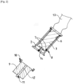
- the receptacle 1 illustrated is configured to receive a cryogenic connection 3 for filling between two uses.
- a connection 3 (sometimes called a nozzle or gun) has, for example, a generally cylindrical shape and is located at one end of a flexible cryogenic fluid transfer pipe 13.
- This connection 3 has at least one valve 14, in particular a self-sealing valve which is shown schematically.
- the receptacle 1 comprises a body in the form of a tubular sheath 2.
- This sheath has an inlet 5 and a bottom 4 and delimits a tubular housing configured to accommodate the connector 3.
- the sheath 2 is formed of preferably thermally insulated walls.
- the bottom 4 can be located above its inlet 5 in the use configuration so that the terminal end of the connector 3 is kept facing upwards in the stored position in the receptacle 1.
- the receptacle 1 further comprises a drying module 9 provided with removable attachment member(s) 10 on the end of the tubular sheath 2 delimiting the bottom 4, that is to say that the module 9 drying device can be arranged in a first position hooked onto the end of the sheath 2 and a second position detached from the sheath 2.
- the hooking member(s) 10 can comprise a hook system(s) and/or an elastic deformation attachment system.
- the drying module 9 comprises a channel 12 for circulating the flow of drying gas which opens at one end of the drying module 9.
- the drying module 9 comprises, for example, a heating member, for example a resistor and a source of pressurized drying gas or an end intended to be connected to a source of pressurized drying gas, preferably heated.
- a heating member for example a resistor and a source of pressurized drying gas or an end intended to be connected to a source of pressurized drying gas, preferably heated.
- the bottom 4 of the sheath 2 comprises an admission valve 7 configured to be connected with the circulation channel 12 when the drying module 9 is in its first position and to admit a flow of drying gas into the sheath 2 (cf. [ Fig. 1 ]).
- the sheath 2 also preferably comprises a discharge valve 8 configured to discharge any excess pressure in the sheath 2.
- the inlet valve 7 and/or the outlet valve 8 may be a non-return valve, for example a valve which opens according to the pressure differential to which its ends are subjected.
- the proposed architecture allows in particular to heat/dry the connection 3 but also to keep it isolated from the external environment during its movements. This tends to minimize frost or ice and therefore the probability of leakage of the joints.
- the receptacle has a heating/drying means and a sheath 2 forming a removable waterproof cover allowing the connection to be kept isolated and protected from the outside environment during movement phases.
- the drying module 9 allows the connection 3 in the sheath 2 to be heated and/or dried.
- This drying can be ensured by a circulation of dry gas (air or nitrogen for example).
- dry gas air or nitrogen for example.
- the sheath 2 makes it possible to isolate the connection 3 from the external environment.
- This sheath can be mechanically connected to the drying module 9 to allow the connection 3 to be heated.
- This sheath 2 is preferably watertight, as is its mechanical connection with the connector 3.
- the assembly comprising the sheath 2 and the drying module 9 can be oriented so as to facilitate the evacuation of water but also to ensure that the droplets and crystals blown during defrosting do not collect near the valve 14 of the connector.
- sheath 2 can be oriented in any orientation but preferred orientations would be 60° to 30° (end with bottom 4 nose pointing down) and -30° to -90° (end with bottom 4 pointing up).
- drying gas inlet 7 and outlet 8 can be positioned to optimize heating/drying.
- a use case may include some or all of the following steps.
- connector 3 After using the connector (filling a tank for example) connector 3 is separated from the filled tank.
- the sheath 2 is slipped onto the fitting 3 (or the fitting is inserted into the sheath 2).
- the sheath 2 is mechanically and tightly connected to the fitting 3. This is preferably achieved with a level of tightness determined relative to the external environment to ensure insulation from moisture.
- the assembly comprising the connector 3 and the sheath 2 can be moved towards the drying module 9 (or vice versa) while being protected from the external environment.
- the assembly comprising the connector 3 and the sheath 2 is mechanically connected to the drying module 9.
- drying gas can be put into circulation to sweep the connection 3 in the sheath 2. This makes it possible to evacuate the frost which has deposited.
- the triggering of this sweep can be triggered manually and/or by the detection of the connection and/or after the connection 3 has cooled down, that is to say before the next filling (or after).
- This gas sweep can be planned for a predetermined duration, for example between 2 and 120 min and/or according to a predetermined measured temperature threshold reached (for example between zero and -70°C).
- a temperature probe can be installed in the sheath 2 to determine the end of defrosting (and the start of vacuum drawing if applicable).
- connection 3 is ready for the next filling.
- the connector 3 with its sheath 2 can be separated from the drying module 9 and moved towards the tank to be filled while being protected from the outside environment (via the sheath 2). During this step, the connector 3 and the sheath 2 remain attached but are separated from the drying module 9.
- the sheath 2 can be removed from the connection 3 and the connection 3 can be connected to the tank to be filled.
- the drying gas may be nitrogen, dry air, helium or any other suitable gas or mixture.
- This drying gas can be preheated to accelerate drying (in module 9 or upstream). Heating can be achieved by conduction and/or gas circulation.
- the sheath can be vacuum sealed.
- the sheath 2 may have a double-walled structure with thermal insulation.
- This thermal insulation may include a vacuum (with multi-layer insulation and/or foams, silica, etc.), or without a vacuum (foams, fiberglass, etc.).
- This inter-wall space may or may not communicate with the internal space of the sheath 2. In the case of communication, this may allow the two volumes to be jointly vacuum-sealed during use.
- the external face of the internal wall of the double wall can be coated with a coating or a particular surface condition having a reflection coefficient limiting thermal inputs by radiation.
- connection 3 in the sheath 2 can be carried out optically and/or mechanically and/or inductively.
- the receptacle has a sheath 2 forming a preferably removable sealed cover which minimizes frost or ice and therefore the probability of leakage of the valve seals 14 or the entry of ice into the lines/tank.
- This sheath can be mechanically detachable from the drying module 9.
- the invention is particularly advantageous for use in liquid hydrogen tank filling stations (cars, trucks, airplanes, boats) to minimize the time between two successive fillings and to limit leaks due to frost.
- the structure is particularly advantageous for filling installations (boat type) where the distance to be covered is relatively large between the station receptacle and the tank to be filled.
Landscapes
- Engineering & Computer Science (AREA)
- General Engineering & Computer Science (AREA)
- Mechanical Engineering (AREA)
- Filling Or Discharging Of Gas Storage Vessels (AREA)
Abstract
Description
- L'invention concerne un réceptacle pour recevoir un raccord cryogénique et un ensemble comprenant un tel réceptacle et un raccord cryogénique.
- L'invention concerne plus particulièrement un réceptacle pour recevoir un raccord cryogénique de remplissage entre deux utilisations, le réceptacle comprenant un fourreau tubulaire comportant une entrée et un fond et délimitant un logement tubulaire configuré pour accueillir de façon étanche un raccord de forme générale cylindrique.
- Pour raccourcir les durées des phases de connexions et de déconnexions de flexibles de transfert de fluides cryogéniques (LNG, LH2, ...) on utilise des raccords (ou buses) de type à connexion rapide.
- Ces technologies permettent une auto-obturation de l'extrémité du raccord qui réduit le besoin de purge et de réchauffage par rapport à des raccords type classiques de type "Johnston".
- Cette technologie permet notamment une déconnexion à froid du raccord. Après la déconnexion, le raccord est froid, ce qui provoque généralement un dépôt de givre (voir la condensation d'air autour du raccord pour le cas de l'hydrogène). Ce givre doit être évacué pour éviter que cette eau se loge dans les volumes morts du raccord (ceci peut générer une fuite ou une accumulation de glace au fur et à mesure de l'utilisation du flexible).
- Si la durée entre deux remplissages est trop longue (notamment pendant la nuit), les entrées thermiques sur le flexibles imposent de remettre à chaud le flexible pour limiter la montée en pression. Ceci implique de devoir refaire une mise en froid du flexible avant le prochaine utilisation. Ceci allonge les durées des transferts de fluide.
- Dans certaines configurations, raccourcir les durées des remplissages est un enjeu clé.
- Dans la plupart des stations de remplissage de carburant, les flexibles sont munis de raccords ou pistolets avec des réceptacles de rangements entre les différents remplissages.
- Pour les fluides froids ou cryogéniques, il est connu de nettoyer les raccords suite à leur utilisation pour enlever les dépôts de givre qui se forment. Cela peut notamment être fait directement dans le réceptacle en soufflant de l'air sec lorsque celui-ci est rangé.
- Les documents
WO21093985A1 FR3104671A1 US20180354778A1 décrivent des réceptacles pour raccords cryogéniques mais qui répondent imparfaitement aux exigences d'utilisation. - Le besoin de réchauffage/séchage avant chaque remplissage devient donc crucial pour éviter les dépôts de givre/glace.
- Un but de la présente invention est de pallier tout ou partie des inconvénients de l'art antérieur relevés ci-dessus.
- A cette fin, le réceptacle selon l'invention, par ailleurs conforme à la définition générique qu'en donne le préambule ci-dessus, est essentiellement caractérisé en ce que le réceptacle comprenant en outre un module de séchage muni d'organe(s) d'accrochage amovible sur l'extrémité du fourreau tubulaire délimitant le fond, c'est-dire que le module de séchage peut être disposé dans une première position accroché sur l'extrémité du fourreau et une seconde position détachée du fourreau, le module de séchage comprenant un canal de circulation de flux de gaz de séchage, le fond du fourreau comprenant un clapet d'admission configuré pour être relié avec le canal de circulation lorsque le module de séchage est dans sa première position et admettre un flux de gaz de séchage dans le fourreau, le réceptacle comportant un ensemble de joint(s) d'étanchéité configuré(s) pour coopérer avec le raccord et isoler le volume intérieur du fourreau par rapport à l'extérieur du fourreau.
- Par ailleurs, des modes de réalisation de l'invention peuvent comporter l'une ou plusieurs des caractéristiques suivantes :
- le clapet d'admission est un clapet anti-retour,
- le fourreau comprend un clapet d'évacuation configuré pour évacuer une éventuelle surpression dans le fourreau, le clapet d'évacuation étant par exemple un clapet anti-retour,
- le module de séchage comprend un organe de chauffage, par exemple une résistance et une source de gaz de séchage sous pression ou une extrémité destinée à être reliée à une source de gaz de séchage sous pression chauffé,
- le fourreau tubulaire est isolé thermiquement, par exemple à structure à double parois isolée sous vide entre les parois,
- le réceptacle comporte un mécanisme de verrouillage configuré pour coopérer avec le raccord et assurer blocage amovible du raccord dans le fourreau,
- le réceptacle comporte un détecteur de présence de raccord dans le fourreau et/ou un capteur de température dans le fourreau,
- le réceptacle comporte un système de mise au vide du volume interne du fourreau.
- L'invention concerne également un ensemble comprenant une conduite de transfert de fluide munie d'un raccord fluidique et un réceptacle selon l'une quelconque des caractéristiques ci-dessus ou ci-dessous, comprenant un ensemble de joint(s) torique(s) d'étanchéité disposé(s) au niveau de l'entrée du fourreau et/ou sur le raccord.
- L'invention peut concerner également tout dispositif ou procédé alternatif comprenant toute combinaison des caractéristiques ci-dessus ou ci-dessous dans le cadre des revendications. D'autres particularités et avantages apparaîtront à la lecture de la description ci-après, faite en référence aux figures.
- L'invention sera mieux comprise à la lecture de la description qui va suivre donnée uniquement à titre d'exemple et faite en se référant aux dessins annexés dans lesquels :
- [
Fig. 1 ] est une vue schématique en coupe d'un réceptacle selon un mode de réalisation possible de l'invention dans une première configuration, - [
Fig. 2 ] est une vue schématique en coupe du réceptacle précité dans une seconde configuration, - [
Fig. 3 ] est une vue schématique en coupe du réceptacle précité dans une troisième configuration, - Sur toutes les figures, les mêmes références se rapportent aux mêmes éléments.
- Dans cette description détaillée, les réalisations suivantes sont des exemples. Bien que la description se réfère à un ou plusieurs modes de réalisation, cela ne signifie pas que les caractéristiques s'appliquent seulement à un seul mode de réalisation. De simples caractéristiques de différents modes de réalisation peuvent également être combinées et/ou interchangées pour fournir d'autres réalisations.
- Le réceptacle 1 illustré est configuré pour recevoir un raccord 3 cryogénique de remplissage entre deux utilisations. Un tel raccord 3 (parfois appelé buse ou pistolet) a par exemple une forme générale cylindrique est situé à une extrémité d'un tuyau 13 flexible de transfert de fluide cryogénique. Ce raccord 3 possède au moins un clapet 14, notamment un clapet auto-obturant qui est représenté schématiquement.
- Le réceptacle 1 comprend un corps en forme de fourreau 2 tubulaire. Ce fourreau comporte une entrée 5 et un fond 4 et délimite un logement tubulaire configuré pour accueillir le raccord 3. Le fourreau 2 est formé de parois de préférence isolées thermiquement.
- Le fond 4 peut être situé au-dessus de son entrée 5 en configuration d'utilisation de sorte que l'extrémité terminale du raccord 3 y est maintenue orientée vers le haut en position rangée dans le réceptacle 1.
- Le réceptacle 1 comprend en outre un module 9 de séchage muni d'organe(s) d'accrochage 10 amovible sur l'extrémité du fourreau 2 tubulaire délimitant le fond 4, c'est-dire que le module 9 de séchage peut être disposé dans une première position accroché sur l'extrémité du fourreau 2 et une seconde position détachée du fourreau 2. Par exemple, les organe(s) d'accrochage 10 peuvent comprendre un système de crochet(s) et/ou un système d'attache par déformation élastique.
- Le module 9 de séchage comprend un canal 12 de circulation de flux de gaz de séchage qui débouche au niveau d'une extrémité du module 9 de séchage.
- Le module 9 de séchage comprend par exemple un organe de chauffage, par exemple une résistance et une source de gaz de séchage sous pression ou une extrémité destinée à être reliée à une source de gaz de séchage sous pression, de préférence chauffé.
- Le fond 4 du fourreau 2 comprend un clapet 7 d'admission configuré pour être relié avec le canal 12 de circulation lorsque le module 9 de séchage est dans sa première position et admettre un flux de gaz de séchage dans le fourreau 2 (cf. [
Fig. 1 ]). - Comme illustré, le fourreau 2 comprend également de préférence un clapet 8 d'évacuation configuré pour évacuer une éventuelle surpression dans le fourreau 2.
- Le clapet 7 d'admission et/ou le clapet 8 d'évacuation peut être un clapet anti-retour, par exemple un clapet qui s'ouvre selon le différentiel de pression auxquelles ses extrémités sont soumises.
- L'architecture proposée permet notamment de réchauffer/sécher le raccord 3 mais aussi de le garder isolé du milieu extérieur lors de ses déplacements. Ceci tend à minimiser le givre ou la glace et donc les probabilités de fuite des joints.
- Le réceptacle possède un moyen de réchauffage/séchage et un fourreau 2 formant un couvercle étanche amovible permettant de garder le raccord isolé et protégé du milieu extérieur lors des phases de déplacements.
- Le module 9 de séchage permet de réchauffer et/ou sécher le raccord 3 dans le fourreau 2.
- Ce séchage peut être assuré par une circulation de gaz sec (air ou azote par exemple). Le fourreau 2 permet d'isoler le raccord 3 du milieu extérieur. Ce fourreau peut être raccordé mécaniquement au module 9 de séchage pour permettre le réchauffage du raccord 3.
- Ce fourreau 2 est de préférence étanche tout comme sa liaison mécanique avec le raccord 3. L'ensemble fourreau 2 et module 9 de séchage peut être est orienté de façon à faciliter l'évacuation de l'eau mais aussi pour garantir que les gouttelettes et cristaux soufflés lors du dégivrage ne s'amassent pas à proximité du clapet 14 du raccord.
- Par exemple, le fourreau 2 peut être orienté suivant n'importe quelle orientation mais les orientations préférées seraient de 60° à 30° (extrémité avec le fond 4 nez pointant vers le bas) et -30° à -90° (extrémité avec le fond 4 pointant vers le haut).
- De même, les entrée 7 et sortie 8 du gaz de séchage peuvent être placés de manière à optimiser le réchauffage/séchage.
- Un exemple d'utilisation peut comporter tout ou partie des étapes suivantes.
- Après utilisation du raccord (remplissage d'un réservoir par exemple) le raccord 3 est séparé du réservoir rempli.
- Le fourreau 2 est enfilé sur le raccord 3 (ou le raccord est introduit dans le fourreau 2). Le fourreau 2 est relié mécaniquement et de façon étanche au raccord 3. Ceci est réalisé de préférence avec un niveau d'étanchéité déterminé par rapport au milieu extérieur pour assurer une isolation vis-à-vis de l'humidité.
- L'ensemble comprenant le raccord 3 et le fourreau 2 peut être déplacé vers le module de séchage 9 (ou inversement) en étant protégé du milieu extérieur.
- L'ensemble comprenant le raccord 3 et le fourreau 2 est raccordé mécaniquement au module 9 de séchage.
- Après un éventuel verrouillage mécanique 10 entre le fourreau 2 et le module 9 de séchage, du gaz de séchage peut être mis en circulation pour balayer le raccord 3 dans le fourreau 2. Ceci permet d'évacuer le givre qui s'est déposé. Le déclenchement de ce balayage peut être déclencher manuellement et/ou par la détection du raccordement et/ou après la mise en froid du raccord 3, c'est-à-dire avant le prochain remplissage (ou après).
- Ce balayage gazeux peut être prévu pour une durée prédéterminée, par exemple entre 2 et 120min et/ou en fonction d'un seuil de température prédéterminé mesuré atteint (par exemple entre zéro et -70°C). Une sonde de température peut être installée dans le fourreau 2 pour déterminer la fin du dégivrage (et l'amorce du tirage au vide le cas échéant).
- Lorsque le balayage de gaz est interrompu le raccord 3 est prêt pour le prochain remplissage.
- Avant le prochain remplissage, le raccord 3 muni de son fourreau 2 peut être séparé du module 9 de séchage et être déplacé vers le réservoir à remplir en étant protégé du milieu extérieur (via le fourreau 2). Pendant cette étape, le raccord 3 et le fourreau 2 restent solidaires mais sont séparés du module 9 de séchage.
- A proximité du réservoir à remplir, le fourreau 2 peut être retiré du raccord 3 et le raccord 3 peut être raccordé au réservoir à remplir.
- Le gaz de séchage peut être de l'azote, de l'air sec, de l'hélium ou tout autre gaz ou mélange approprié.
- Ce gaz de séchage peut être préchauffé pour accélérer le séchage (dans le module 9 ou en amont). Le chauffage peut être réalisé par conduction et/ou circulation de gaz.
- On pourrait envisager de rendre monobloc le mode de chauffage et le fourreau 2.
- Le fourreau peut être mis sous vide.
- Le fourreau 2 peut être à structure à double paroi avec isolation thermique. Cette isolation thermique comprendre un vide (avec isolation multicouches et/ou mousses, silice, ...), ou sans vide (mousses, fibre de verre, ...). Cet espace inter-parois peut être communicant ou non avec l'espace interne du fourreau 2. En cas de communication, ceci peut permettre mettre sous vide conjointement les deux volumes lors de l'utilisation.
- La face externe de la paroi interne de la double paroi (surface en regard de l'espace inter paroi) peut être revêtue d'un revêtement ou un état de surface particulier ayant coefficient de réflexion limitant les entrées thermiques par radiation.
- La détection du raccord 3 dans le fourreau 2 peut être réalisée de façon optique et/ou mécanique et/ou inductive.
- Il est possible de prévoir un collecteur pour faciliter la gestion et l'évacuation de l'eau récupérée en bas du fourreau 2.
- Ainsi, le réceptacle possède un fourreau 2 formant un couvercle de préférence étanche amovible qui minimise le givre ou la glace et donc les probabilités de fuite des joints de clapet 14 ou l'entrée de glace dans les lignes/réservoir. Ce fourreau peut être détachable mécaniquement du module 9 de séchage.
- L'invention est particulièrement avantageuse pour une utilisation dans des stations de remplissage de réservoirs d'hydrogène liquide (voitures, camions, avions, bateau) pour minimiser les temps entre deux remplissages successifs et pour limiter les fuites dues au givre. La structure est particulièrement avantageuse pour les installations de remplissage (type bateau) où la distance à parcourir est relativement grande entre le réceptacle de la station et le réservoir à remplir.
Claims (9)
- Réceptacle pour recevoir un raccord (3) cryogénique de remplissage entre deux utilisations, le réceptacle (1) comprenant un fourreau (2) tubulaire comportant une entrée (5) et un fond (4) et délimitant un logement tubulaire configuré pour accueillir de façon étanche un raccord (3) de forme générale cylindrique, le réceptacle (1) comprenant en outre un module (9) de séchage muni d'organe(s) d'accrochage (10) amovible sur l'extrémité du fourreau (2) tubulaire délimitant le fond (4), c'est-dire que le module (9) de séchage peut être disposé dans une première position accroché sur l'extrémité du fourreau (2) et une seconde position détachée du fourreau (2), le module (9) de séchage comprenant un canal (12) de circulation de flux de gaz de séchage, le fond (4) du fourreau (2) comprenant un clapet (7) d'admission configuré pour être relié avec le canal (12) de circulation lorsque le module (9) de séchage est dans sa première position et admettre un flux de gaz de séchage dans le fourreau (2), le réceptacle comportant un ensemble de joint(s) (6) d'étanchéité configuré(s) pour coopérer avec le raccord (3) et isoler le volume intérieur du fourreau par rapport à l'extérieur du fourreau (2).
- Réceptacle selon la revendication 1, caractérisé en ce que le clapet (7) d'admission est un clapet anti-retour.
- Réceptacle selon la revendication 1 ou 2, caractérisé en ce que le fourreau (2) comprend un clapet (8) d'évacuation configuré pour évacuer une éventuelle surpression dans le fourreau (2), le clapet (8) d'évacuation étant par exemple un clapet anti-retour.
- Réceptacle selon l'une quelconque des revendications 1 à 3, caractérisé en ce que le module (9) de séchage comprend un organe de chauffage, par exemple une résistance et une source de gaz de séchage sous pression ou une extrémité destinée à être reliée à une source de gaz de séchage sous pression chauffé.
- Réceptacle selon l'une quelconque des revendications 1 à 4, caractérisé en ce que le fourreau (2) tubulaire est isolé thermiquement, par exemple à structure à double parois isolée sous vide entre les parois.
- Réceptacle selon l'une quelconque des revendications 1 à 5, caractérisée en ce qu'il comporte un mécanisme (12) de verrouillage configuré pour coopérer avec le raccord (3) et assurer blocage amovible du raccord (3) dans le fourreau (2).
- Réceptacle selon l'une quelconque des revendications 1 à 6, caractérisé en ce qu'il comporte un détecteur (12) de présence de raccord dans le fourreau (2) et/ou un capteur de température dans le fourreau (2).
- Réceptacle selon l'une quelconque des revendications 1 à 7, caractérisé en ce qu'il comporte un système de mise au vide du volume interne du fourreau (2)
- Ensemble comprenant un conduite (13) de transfert de fluide munie d'un raccord (3) fluidique et un réceptacle selon l'une quelconque des revendications 1 à 8, caractérisé en ce que qu'il comprend ensemble de joint(s) (6) torique(s) d'étanchéité disposé(s) au niveau de l'entrée (5) du fourreau et/ou sur le raccord (3).
Applications Claiming Priority (1)
| Application Number | Priority Date | Filing Date | Title |
|---|---|---|---|
| FR2309431A FR3152859B1 (fr) | 2023-09-07 | 2023-09-07 | Réceptacle pour raccord cryogénique et ensemble comprenant un tel réceptacle |
Publications (2)
| Publication Number | Publication Date |
|---|---|
| EP4521016A1 true EP4521016A1 (fr) | 2025-03-12 |
| EP4521016B1 EP4521016B1 (fr) | 2026-04-01 |
Family
ID=89474856
Family Applications (1)
| Application Number | Title | Priority Date | Filing Date |
|---|---|---|---|
| EP24190210.5A Active EP4521016B1 (fr) | 2023-09-07 | 2024-07-23 | Réceptacle pour raccord cryogénique et ensemble comprenant un tel réceptacle |
Country Status (6)
| Country | Link |
|---|---|
| US (1) | US20250084962A1 (fr) |
| EP (1) | EP4521016B1 (fr) |
| JP (1) | JP2025038883A (fr) |
| KR (1) | KR20250037367A (fr) |
| CN (1) | CN119572843A (fr) |
| FR (1) | FR3152859B1 (fr) |
Citations (5)
| Publication number | Priority date | Publication date | Assignee | Title |
|---|---|---|---|---|
| US5301723A (en) * | 1992-11-06 | 1994-04-12 | Hydra Rig, Inc. | Apparatus and method of preventing ice accumulation on coupling valves for cryogenic fluids |
| US20180354778A1 (en) | 2017-06-08 | 2018-12-13 | Bpc Acquisition Company | Fuel dispenser including a nozzle dryer |
| WO2021093985A1 (fr) | 2019-11-15 | 2021-05-20 | Cryostar Sas | Réceptacle pour connecteur cryogénique |
| FR3104671A1 (fr) | 2019-12-11 | 2021-06-18 | L'air Liquide, Societe Anonyme Pour L'etude Et L'exploitation Des Procedes Georges Claude | Dispositif de distribution de carburant gazeux |
| WO2022225442A1 (fr) * | 2021-04-22 | 2022-10-27 | Mann Teknik Ab | Dispositif et procédé de séchage d'une buse pour gaz liquéfié |
-
2023
- 2023-09-07 FR FR2309431A patent/FR3152859B1/fr active Active
-
2024
- 2024-07-23 EP EP24190210.5A patent/EP4521016B1/fr active Active
- 2024-08-08 CN CN202411083983.XA patent/CN119572843A/zh active Pending
- 2024-09-03 JP JP2024151160A patent/JP2025038883A/ja active Pending
- 2024-09-04 KR KR1020240119894A patent/KR20250037367A/ko active Pending
- 2024-09-05 US US18/825,552 patent/US20250084962A1/en active Pending
Patent Citations (5)
| Publication number | Priority date | Publication date | Assignee | Title |
|---|---|---|---|---|
| US5301723A (en) * | 1992-11-06 | 1994-04-12 | Hydra Rig, Inc. | Apparatus and method of preventing ice accumulation on coupling valves for cryogenic fluids |
| US20180354778A1 (en) | 2017-06-08 | 2018-12-13 | Bpc Acquisition Company | Fuel dispenser including a nozzle dryer |
| WO2021093985A1 (fr) | 2019-11-15 | 2021-05-20 | Cryostar Sas | Réceptacle pour connecteur cryogénique |
| FR3104671A1 (fr) | 2019-12-11 | 2021-06-18 | L'air Liquide, Societe Anonyme Pour L'etude Et L'exploitation Des Procedes Georges Claude | Dispositif de distribution de carburant gazeux |
| WO2022225442A1 (fr) * | 2021-04-22 | 2022-10-27 | Mann Teknik Ab | Dispositif et procédé de séchage d'une buse pour gaz liquéfié |
Also Published As
| Publication number | Publication date |
|---|---|
| CN119572843A (zh) | 2025-03-07 |
| EP4521016B1 (fr) | 2026-04-01 |
| FR3152859A1 (fr) | 2025-03-14 |
| US20250084962A1 (en) | 2025-03-13 |
| KR20250037367A (ko) | 2025-03-17 |
| FR3152859B1 (fr) | 2025-08-15 |
| JP2025038883A (ja) | 2025-03-19 |
Similar Documents
| Publication | Publication Date | Title |
|---|---|---|
| EP4174357B1 (fr) | Ensemble de connexion optimisé entre deux portions d'une canalisation pour le transport d'un fluide cryogénique, comprenant une chambre d'isolation thermique additionnelle et une chambre d'expansion de fluide | |
| US20220282837A1 (en) | Cryogenic fluid coupling | |
| EP3472509B1 (fr) | Structure de dome gaz pour une cuve etanche et thermiquement isolante | |
| EP3899472B1 (fr) | Procede de controle de l'etancheite d'une cuve etanche et thermiquement isolante de stockage d'un fluide | |
| FR3119007A1 (fr) | Dispositif d’accouplement et de détachement d’urgence | |
| FR2697074A1 (fr) | Réservoir cryogénique. | |
| WO2020120860A1 (fr) | Tour de chargement et/ou de dechargement d'une cuve d'un navire et cuve comportant une telle tour | |
| EP4083489B1 (fr) | Connecteur | |
| FR3073040A1 (fr) | Dispositifs de securite pour installations aerauliques de froid et pompes a chaleur utilisant des fluides frigorigenes toxiques ou inflammables | |
| EP4521016B1 (fr) | Réceptacle pour raccord cryogénique et ensemble comprenant un tel réceptacle | |
| FR3154149A1 (fr) | Ensemble propulsif pour aéronef | |
| WO2023151845A1 (fr) | Dispositif et procédé de stockage et de fourniture de fluide | |
| WO2024146735A1 (fr) | Réceptacle pour recevoir un raccord cryogénique | |
| FR2700386A1 (fr) | Manchon thermique rigide pour fût d'un canon. | |
| WO2023134912A1 (fr) | Dispositif d'accouplement et son procédé de purge | |
| CA2131590A1 (fr) | Reservoir de stockage de gaz sous haute pression et installation de stockage et de fourniture de gaz sous haute pression | |
| EP4229382B1 (fr) | Procédé de contrôle de l'étanchéité d'une cuve étanche et thermiquement isolante de stockage d'un fluide | |
| FR2654491A1 (fr) | Dispositif de stockage de liquide, a climatisation. | |
| FR3164770A1 (fr) | Raccord demontable pour tubes cryogeniques a isolation sous vide et procede de raccordement correspondant. | |
| FR3158552A1 (fr) | Raccord cryogénique | |
| FR3140927A3 (fr) | Dispositif mobile de remplissage de réservoirs de fluide cryogénique | |
| FR3151642A1 (fr) | Raccord pour un transfert d’un fluide, en particulier un fluide cryogénique, depuis un réservoir source vers un réservoir récepteur | |
| FR2665239A1 (fr) | Procede et systeme de protection de reseaux de canalisations. | |
| FR2909158A1 (fr) | Coque de protection pour raccords de tuyaux de liquides. | |
| FR2636406A1 (fr) | Dispositif de controle pour reservoir de stockage de combustibles gazeux |
Legal Events
| Date | Code | Title | Description |
|---|---|---|---|
| PUAI | Public reference made under article 153(3) epc to a published international application that has entered the european phase |
Free format text: ORIGINAL CODE: 0009012 |
|
| STAA | Information on the status of an ep patent application or granted ep patent |
Free format text: STATUS: THE APPLICATION HAS BEEN PUBLISHED |
|
| AK | Designated contracting states |
Kind code of ref document: A1 Designated state(s): AL AT BE BG CH CY CZ DE DK EE ES FI FR GB GR HR HU IE IS IT LI LT LU LV MC ME MK MT NL NO PL PT RO RS SE SI SK SM TR |
|
| STAA | Information on the status of an ep patent application or granted ep patent |
Free format text: STATUS: REQUEST FOR EXAMINATION WAS MADE |
|
| 17P | Request for examination filed |
Effective date: 20250912 |
|
| GRAP | Despatch of communication of intention to grant a patent |
Free format text: ORIGINAL CODE: EPIDOSNIGR1 |
|
| STAA | Information on the status of an ep patent application or granted ep patent |
Free format text: STATUS: GRANT OF PATENT IS INTENDED |
|
| RIC1 | Information provided on ipc code assigned before grant |
Ipc: F17C 13/00 20060101AFI20251024BHEP |
|
| INTG | Intention to grant announced |
Effective date: 20251106 |
|
| GRAS | Grant fee paid |
Free format text: ORIGINAL CODE: EPIDOSNIGR3 |
|
| GRAA | (expected) grant |
Free format text: ORIGINAL CODE: 0009210 |
|
| STAA | Information on the status of an ep patent application or granted ep patent |
Free format text: STATUS: THE PATENT HAS BEEN GRANTED |
|
| AK | Designated contracting states |
Kind code of ref document: B1 Designated state(s): AL AT BE BG CH CY CZ DE DK EE ES FI FR GB GR HR HU IE IS IT LI LT LU LV MC ME MK MT NL NO PL PT RO RS SE SI SK SM TR |
|
| REG | Reference to a national code |
Ref country code: CH Ref legal event code: F10 Free format text: ST27 STATUS EVENT CODE: U-0-0-F10-F00 (AS PROVIDED BY THE NATIONAL OFFICE) Effective date: 20260401 Ref country code: GB Ref legal event code: FG4D Free format text: NOT ENGLISH |
|
| REG | Reference to a national code |
Ref country code: IE Ref legal event code: FG4D Free format text: LANGUAGE OF EP DOCUMENT: FRENCH |
|
| REG | Reference to a national code |
Ref country code: DE Ref legal event code: R096 Ref document number: 602024003593 Country of ref document: DE |
|
| REG | Reference to a national code |
Ref country code: NL Ref legal event code: MP Effective date: 20260401 |