EP4520969A1 - Lubricating-oil monitoring system and vacuum pump system - Google Patents
Lubricating-oil monitoring system and vacuum pump system Download PDFInfo
- Publication number
- EP4520969A1 EP4520969A1 EP24198383.2A EP24198383A EP4520969A1 EP 4520969 A1 EP4520969 A1 EP 4520969A1 EP 24198383 A EP24198383 A EP 24198383A EP 4520969 A1 EP4520969 A1 EP 4520969A1
- Authority
- EP
- European Patent Office
- Prior art keywords
- oil
- lubricating
- light
- lubricating oil
- bearing
- Prior art date
- Legal status (The legal status is an assumption and is not a legal conclusion. Google has not performed a legal analysis and makes no representation as to the accuracy of the status listed.)
- Pending
Links
Images



Classifications
-
- G—PHYSICS
- G01—MEASURING; TESTING
- G01N—INVESTIGATING OR ANALYSING MATERIALS BY DETERMINING THEIR CHEMICAL OR PHYSICAL PROPERTIES
- G01N21/00—Investigating or analysing materials by the use of optical means, i.e. using sub-millimetre waves, infrared, visible or ultraviolet light
- G01N21/17—Systems in which incident light is modified in accordance with the properties of the material investigated
- G01N21/25—Colour; Spectral properties, i.e. comparison of effect of material on the light at two or more different wavelengths or wavelength bands
- G01N21/251—Colorimeters; Construction thereof
-
- F—MECHANICAL ENGINEERING; LIGHTING; HEATING; WEAPONS; BLASTING
- F04—POSITIVE - DISPLACEMENT MACHINES FOR LIQUIDS; PUMPS FOR LIQUIDS OR ELASTIC FLUIDS
- F04B—POSITIVE-DISPLACEMENT MACHINES FOR LIQUIDS; PUMPS
- F04B37/00—Pumps having pertinent characteristics not provided for in, or of interest apart from, groups F04B25/00 - F04B35/00
- F04B37/10—Pumps having pertinent characteristics not provided for in, or of interest apart from, groups F04B25/00 - F04B35/00 for special use
- F04B37/14—Pumps having pertinent characteristics not provided for in, or of interest apart from, groups F04B25/00 - F04B35/00 for special use to obtain high vacuum
-
- F—MECHANICAL ENGINEERING; LIGHTING; HEATING; WEAPONS; BLASTING
- F04—POSITIVE - DISPLACEMENT MACHINES FOR LIQUIDS; PUMPS FOR LIQUIDS OR ELASTIC FLUIDS
- F04C—ROTARY-PISTON, OR OSCILLATING-PISTON, POSITIVE-DISPLACEMENT MACHINES FOR LIQUIDS; ROTARY-PISTON, OR OSCILLATING-PISTON, POSITIVE-DISPLACEMENT PUMPS
- F04C28/00—Control of, monitoring of, or safety arrangements for, pumps or pumping installations specially adapted for elastic fluids
- F04C28/28—Safety arrangements; Monitoring
-
- F—MECHANICAL ENGINEERING; LIGHTING; HEATING; WEAPONS; BLASTING
- F04—POSITIVE - DISPLACEMENT MACHINES FOR LIQUIDS; PUMPS FOR LIQUIDS OR ELASTIC FLUIDS
- F04B—POSITIVE-DISPLACEMENT MACHINES FOR LIQUIDS; PUMPS
- F04B39/00—Component parts, details, or accessories, of pumps or pumping systems specially adapted for elastic fluids, not otherwise provided for in, or of interest apart from, groups F04B25/00 - F04B37/00
- F04B39/02—Lubrication
- F04B39/0207—Lubrication with lubrication control systems
-
- F—MECHANICAL ENGINEERING; LIGHTING; HEATING; WEAPONS; BLASTING
- F04—POSITIVE - DISPLACEMENT MACHINES FOR LIQUIDS; PUMPS FOR LIQUIDS OR ELASTIC FLUIDS
- F04B—POSITIVE-DISPLACEMENT MACHINES FOR LIQUIDS; PUMPS
- F04B49/00—Control, e.g. of pump delivery, or pump pressure of, or safety measures for, machines, pumps, or pumping installations, not otherwise provided for, or of interest apart from, groups F04B1/00 - F04B47/00
- F04B49/06—Control using electricity
- F04B49/065—Control using electricity and making use of computers
-
- F—MECHANICAL ENGINEERING; LIGHTING; HEATING; WEAPONS; BLASTING
- F04—POSITIVE - DISPLACEMENT MACHINES FOR LIQUIDS; PUMPS FOR LIQUIDS OR ELASTIC FLUIDS
- F04B—POSITIVE-DISPLACEMENT MACHINES FOR LIQUIDS; PUMPS
- F04B53/00—Component parts, details or accessories not provided for in, or of interest apart from, groups F04B1/00 - F04B23/00 or F04B39/00 - F04B47/00
- F04B53/18—Lubricating
-
- F—MECHANICAL ENGINEERING; LIGHTING; HEATING; WEAPONS; BLASTING
- F04—POSITIVE - DISPLACEMENT MACHINES FOR LIQUIDS; PUMPS FOR LIQUIDS OR ELASTIC FLUIDS
- F04C—ROTARY-PISTON, OR OSCILLATING-PISTON, POSITIVE-DISPLACEMENT MACHINES FOR LIQUIDS; ROTARY-PISTON, OR OSCILLATING-PISTON, POSITIVE-DISPLACEMENT PUMPS
- F04C18/00—Rotary-piston pumps specially adapted for elastic fluids
- F04C18/08—Rotary-piston pumps specially adapted for elastic fluids of intermeshing-engagement type, i.e. with engagement of co-operating members similar to that of toothed gearing
- F04C18/12—Rotary-piston pumps specially adapted for elastic fluids of intermeshing-engagement type, i.e. with engagement of co-operating members similar to that of toothed gearing of other than internal-axis type
- F04C18/123—Rotary-piston pumps specially adapted for elastic fluids of intermeshing-engagement type, i.e. with engagement of co-operating members similar to that of toothed gearing of other than internal-axis type with radially or approximately radially from the rotor body extending tooth-like elements, co-operating with recesses in the other rotor, e.g. one tooth
-
- F—MECHANICAL ENGINEERING; LIGHTING; HEATING; WEAPONS; BLASTING
- F04—POSITIVE - DISPLACEMENT MACHINES FOR LIQUIDS; PUMPS FOR LIQUIDS OR ELASTIC FLUIDS
- F04C—ROTARY-PISTON, OR OSCILLATING-PISTON, POSITIVE-DISPLACEMENT MACHINES FOR LIQUIDS; ROTARY-PISTON, OR OSCILLATING-PISTON, POSITIVE-DISPLACEMENT PUMPS
- F04C18/00—Rotary-piston pumps specially adapted for elastic fluids
- F04C18/08—Rotary-piston pumps specially adapted for elastic fluids of intermeshing-engagement type, i.e. with engagement of co-operating members similar to that of toothed gearing
- F04C18/12—Rotary-piston pumps specially adapted for elastic fluids of intermeshing-engagement type, i.e. with engagement of co-operating members similar to that of toothed gearing of other than internal-axis type
- F04C18/126—Rotary-piston pumps specially adapted for elastic fluids of intermeshing-engagement type, i.e. with engagement of co-operating members similar to that of toothed gearing of other than internal-axis type with radially from the rotor body extending elements, not necessarily co-operating with corresponding recesses in the other rotor, e.g. lobes, Roots type
-
- F—MECHANICAL ENGINEERING; LIGHTING; HEATING; WEAPONS; BLASTING
- F04—POSITIVE - DISPLACEMENT MACHINES FOR LIQUIDS; PUMPS FOR LIQUIDS OR ELASTIC FLUIDS
- F04C—ROTARY-PISTON, OR OSCILLATING-PISTON, POSITIVE-DISPLACEMENT MACHINES FOR LIQUIDS; ROTARY-PISTON, OR OSCILLATING-PISTON, POSITIVE-DISPLACEMENT PUMPS
- F04C25/00—Adaptations of pumps for special use of pumps for elastic fluids
- F04C25/02—Adaptations of pumps for special use of pumps for elastic fluids for producing high vacuum
-
- F—MECHANICAL ENGINEERING; LIGHTING; HEATING; WEAPONS; BLASTING
- F04—POSITIVE - DISPLACEMENT MACHINES FOR LIQUIDS; PUMPS FOR LIQUIDS OR ELASTIC FLUIDS
- F04C—ROTARY-PISTON, OR OSCILLATING-PISTON, POSITIVE-DISPLACEMENT MACHINES FOR LIQUIDS; ROTARY-PISTON, OR OSCILLATING-PISTON, POSITIVE-DISPLACEMENT PUMPS
- F04C29/00—Component parts, details or accessories of pumps or pumping installations, not provided for in groups F04C18/00 - F04C28/00
- F04C29/02—Lubrication; Lubricant separation
-
- G—PHYSICS
- G01—MEASURING; TESTING
- G01N—INVESTIGATING OR ANALYSING MATERIALS BY DETERMINING THEIR CHEMICAL OR PHYSICAL PROPERTIES
- G01N21/00—Investigating or analysing materials by the use of optical means, i.e. using sub-millimetre waves, infrared, visible or ultraviolet light
- G01N21/17—Systems in which incident light is modified in accordance with the properties of the material investigated
- G01N21/25—Colour; Spectral properties, i.e. comparison of effect of material on the light at two or more different wavelengths or wavelength bands
- G01N21/255—Details, e.g. use of specially adapted sources, lighting or optical systems
-
- G—PHYSICS
- G01—MEASURING; TESTING
- G01N—INVESTIGATING OR ANALYSING MATERIALS BY DETERMINING THEIR CHEMICAL OR PHYSICAL PROPERTIES
- G01N21/00—Investigating or analysing materials by the use of optical means, i.e. using sub-millimetre waves, infrared, visible or ultraviolet light
- G01N21/84—Systems specially adapted for particular applications
- G01N21/88—Investigating the presence of flaws or contamination
- G01N21/8806—Specially adapted optical and illumination features
-
- G—PHYSICS
- G01—MEASURING; TESTING
- G01N—INVESTIGATING OR ANALYSING MATERIALS BY DETERMINING THEIR CHEMICAL OR PHYSICAL PROPERTIES
- G01N21/00—Investigating or analysing materials by the use of optical means, i.e. using sub-millimetre waves, infrared, visible or ultraviolet light
- G01N21/84—Systems specially adapted for particular applications
- G01N21/88—Investigating the presence of flaws or contamination
- G01N21/94—Investigating contamination, e.g. dust
-
- G—PHYSICS
- G01—MEASURING; TESTING
- G01N—INVESTIGATING OR ANALYSING MATERIALS BY DETERMINING THEIR CHEMICAL OR PHYSICAL PROPERTIES
- G01N33/00—Investigating or analysing materials by specific methods not covered by groups G01N1/00 - G01N31/00
- G01N33/26—Oils; Viscous liquids; Paints; Inks
- G01N33/28—Oils, i.e. hydrocarbon liquids
- G01N33/2888—Lubricating oil characteristics, e.g. deterioration
-
- F—MECHANICAL ENGINEERING; LIGHTING; HEATING; WEAPONS; BLASTING
- F04—POSITIVE - DISPLACEMENT MACHINES FOR LIQUIDS; PUMPS FOR LIQUIDS OR ELASTIC FLUIDS
- F04C—ROTARY-PISTON, OR OSCILLATING-PISTON, POSITIVE-DISPLACEMENT MACHINES FOR LIQUIDS; ROTARY-PISTON, OR OSCILLATING-PISTON, POSITIVE-DISPLACEMENT PUMPS
- F04C2220/00—Application
- F04C2220/10—Vacuum
- F04C2220/12—Dry running
-
- F—MECHANICAL ENGINEERING; LIGHTING; HEATING; WEAPONS; BLASTING
- F04—POSITIVE - DISPLACEMENT MACHINES FOR LIQUIDS; PUMPS FOR LIQUIDS OR ELASTIC FLUIDS
- F04C—ROTARY-PISTON, OR OSCILLATING-PISTON, POSITIVE-DISPLACEMENT MACHINES FOR LIQUIDS; ROTARY-PISTON, OR OSCILLATING-PISTON, POSITIVE-DISPLACEMENT PUMPS
- F04C2240/00—Components
- F04C2240/50—Bearings
-
- F—MECHANICAL ENGINEERING; LIGHTING; HEATING; WEAPONS; BLASTING
- F04—POSITIVE - DISPLACEMENT MACHINES FOR LIQUIDS; PUMPS FOR LIQUIDS OR ELASTIC FLUIDS
- F04C—ROTARY-PISTON, OR OSCILLATING-PISTON, POSITIVE-DISPLACEMENT MACHINES FOR LIQUIDS; ROTARY-PISTON, OR OSCILLATING-PISTON, POSITIVE-DISPLACEMENT PUMPS
- F04C2240/00—Components
- F04C2240/80—Other components
- F04C2240/809—Lubricant sump
-
- F—MECHANICAL ENGINEERING; LIGHTING; HEATING; WEAPONS; BLASTING
- F04—POSITIVE - DISPLACEMENT MACHINES FOR LIQUIDS; PUMPS FOR LIQUIDS OR ELASTIC FLUIDS
- F04C—ROTARY-PISTON, OR OSCILLATING-PISTON, POSITIVE-DISPLACEMENT MACHINES FOR LIQUIDS; ROTARY-PISTON, OR OSCILLATING-PISTON, POSITIVE-DISPLACEMENT PUMPS
- F04C2240/00—Components
- F04C2240/80—Other components
- F04C2240/81—Sensor, e.g. electronic sensor for control or monitoring
-
- F—MECHANICAL ENGINEERING; LIGHTING; HEATING; WEAPONS; BLASTING
- F04—POSITIVE - DISPLACEMENT MACHINES FOR LIQUIDS; PUMPS FOR LIQUIDS OR ELASTIC FLUIDS
- F04C—ROTARY-PISTON, OR OSCILLATING-PISTON, POSITIVE-DISPLACEMENT MACHINES FOR LIQUIDS; ROTARY-PISTON, OR OSCILLATING-PISTON, POSITIVE-DISPLACEMENT PUMPS
- F04C2270/00—Control; Monitoring or safety arrangements
- F04C2270/78—Warnings
-
- F—MECHANICAL ENGINEERING; LIGHTING; HEATING; WEAPONS; BLASTING
- F04—POSITIVE - DISPLACEMENT MACHINES FOR LIQUIDS; PUMPS FOR LIQUIDS OR ELASTIC FLUIDS
- F04C—ROTARY-PISTON, OR OSCILLATING-PISTON, POSITIVE-DISPLACEMENT MACHINES FOR LIQUIDS; ROTARY-PISTON, OR OSCILLATING-PISTON, POSITIVE-DISPLACEMENT PUMPS
- F04C2270/00—Control; Monitoring or safety arrangements
- F04C2270/80—Diagnostics
Definitions
- the present invention relates to a lubricating-oil monitoring system for monitoring a condition of a lubricating oil supplied to a bearing of a vacuum pump and a condition of the bearing, and a vacuum pump system including the lubricating-oil monitoring system.
- a process gas is introduced into a process chamber to perform a certain type of process, such as etching process or CVD process.
- the process gas that has been introduced into the process chamber is exhausted by a vacuum pump.
- the vacuum pump used in these manufacturing processes that require high cleanliness is so-called dry vacuum pump that does not use oil in gas flow passages.
- dry vacuum pump is a positive-displacement vacuum pump having a pair of pump rotors in a pump chamber which are rotated in opposite directions to deliver the gas.
- lubricating oil is used to lubricate and cool a bearing configured to rotatably support a rotation shaft to which a pump rotor is secured.
- the vacuum pump includes a lubricating-oil chamber holding the lubricating oil. When the vacuum pump is in motion, the lubricating oil in the lubricating-oil chamber is supplied to the bearing, lubricates and cools the bearing, and is then returned to the lubricating-oil chamber.
- maintenance e.g., a replacement of the lubricating oil, a replacement of the bearing, or an overhaul of the vacuum pump
- the maintenance is performed based on an accumulated operating time of the vacuum pump, regardless of a condition of the vacuum pump, the maintenance may be performed even on the vacuum pump that is able to continue to operate. Stopping the operation of the vacuum pump that is able to continue to operate for the maintenance of the vacuum pump is inefficient from a viewpoint of cost and operation time.
- the vacuum pump may be forced to make an emergency stop during operation of the vacuum pump, and as a result, loss of wafers or the like that are being processed may occur. Therefore, it is required to monitor the condition of the vacuum pump in order to perform the maintenance of the vacuum pump at an appropriate time.
- the present invention provides a lubricating-oil monitoring system capable of monitoring a condition of a vacuum pump in order to perform maintenance of the vacuum pump at an appropriate time, and a vacuum pump system including the lubricating-oil monitoring system.
- Lubricating oil supplied to a bearing of the vacuum pump is normally colorless and transparent. However, if a substance produced by an abnormality, such as wear of the bearing, or foreign matter derived from a process gas, is mixed into the lubricating oil, a hue of the lubricating oil may change.
- the inventors have found that a condition of the lubricating oil and a condition of the bearing can be judged by optically measuring the lubricating oil.
- a lubricating-oil monitoring system comprising: a lubricating-oil measuring device configured to optically measure lubricating oil supplied to a bearing of a vacuum pump; and a data processor electrically coupled to the lubricating-oil measuring device, wherein the lubricating-oil measuring device includes: an oil inspection chamber into which the lubricating oil is introduced; a light source configured to irradiate the lubricating oil in the oil inspection chamber with inspection light containing red light, green light, and blue light; a first light receiving element configured to receive reflected light from the lubricating oil irradiated with the inspection light; and a second light receiving element configured to receive transmitted light from the lubricating oil irradiated with the inspection light, and the data processor is configured to judge a condition of the lubricating oil and a condition of the bearing based on a combination of a color of the reflected light and a color of the transmitted light.
- the data processor is configured to: resolve each of the reflected light and the transmitted light into a red component, a green component, and a blue component; and judge the condition of the lubricating oil and the condition of the bearing based on intensities of the red component, the green component, and the blue component of each of the reflected light and the transmitted light.
- condition of the lubricating oil and the condition of the bearing include an abnormality in the bearing, contamination of the lubricating oil, and deterioration of the lubricating oil.
- the data processor is configured to judge that an abnormality has occurred in the bearing when the intensities of the red component, the green component, and the blue component of the reflected light are smaller than a predetermined bearing-abnormality threshold value and the intensities of the red component, the green component, and the blue component of the transmitted light are smaller than the predetermined bearing-abnormality threshold value.
- the data processor is configured to judge that the lubricating oil has been contaminated with foreign matter when the intensities of the red component, the green component, and the blue component of the reflected light are larger than a predetermined lubricating-oil-contamination threshold value and the intensities of the red component, the green component, and the blue component of the transmitted light are smaller than the predetermined lubricating-oil-contamination threshold value.
- the data processor is configured to judge that the lubricating oil has been deteriorated when the intensity of the red component of the reflected light is larger than a predetermined lubricating-oil-deterioration threshold value and the intensities of the green component and the blue component of the reflected light are smaller than the lubricating-oil-deterioration threshold value.
- the data processor is configured to: calculate a color difference of the reflected light with respect to a reflected reference color based on the intensities of the red component, the green component, and the blue component of the reflected light; calculate a color difference of the transmitted light with respect to a transmitted reference color based on the intensities of the red component, the green component, and the blue component of the transmitted light; and judge the condition of the lubricating oil and the condition of the bearing based on the color difference of the reflected light and the color difference of the transmitted light.
- the lubricating oil comprises a fluorine-based lubricating oil.
- a vacuum pump system comprising: a vacuum pump; and the above-mentioned lubricating-oil monitoring system, wherein the vacuum pump includes: the bearing; and a housing structure that forms a lubricating-oil chamber holding the lubricating oil, the lubricating-oil measuring device is attached to the housing structure, and the oil inspection chamber communicates with the lubricating-oil chamber.
- the vacuum pump system further comprises: a pump controller configured to control an operation of the vacuum pump, wherein the pump controller is configured to output an alarm signal when the data processor judges that an abnormality has occurred in the bearing, when the data processor judges that the lubricating oil has been contaminated with foreign matter, or when the data processor judges that the lubricating oil has been deteriorated.
- the lubricating-oil monitoring system is configured to judge the condition of the lubricating oil and the condition of the bearing based on the combination of the color of the reflected light and the color of the transmitted light. Therefore, the condition of the lubricating oil and the condition of the bearing can be monitored for maintenance of the vacuum pump at an appropriate time.
- FIG. 1 is a schematic diagram showing an embodiment of a vacuum pump system
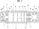
- FIG. 2 is a cross-sectional view of a vacuum pump 1 shown in FIG. 1
- the vacuum pump system includes the vacuum pump 1 configured to evacuate a process gas used in manufacturing of semiconductor devices, liquid crystals, LEDs, solar cells, or the like, and a lubricating-oil monitoring system 30 configured to monitor a condition of lubricating oil and a condition of a bearing used in the vacuum pump 1.
- the vacuum pump 1 of the embodiment described below is a positive-displacement vacuum pump.
- the vacuum pump 1 shown in FIG. 1 is a so-called dry vacuum pump that does not use oil in its flow passages for a gas. Since a vaporized oil does not flow to an upstream side, the dry vacuum pump can be suitably used for a manufacturing apparatus for semiconductor devices or the like that requires high cleanliness.
- the vacuum pump 1 includes a pump casing 2 having a pump chamber 3 therein, pump rotors 5A to 5E arranged in the pump chamber 3, rotation shafts 7 to which the pump rotors 5A to 5E are secured, and electric motor 8 coupled to the rotation shaft 7.
- the pump rotors 5A to 5E and each rotation shaft 7 may be an integral structure. Although only one set of pump rotors 5A to 5E and only one rotation shaft 7 are depicted in FIG. 2 , in this embodiment, a pair of pump rotors 5A to 5E are arranged in the pump chamber 3, and the pair of pump rotors 5A to 5E are secured to a pair of rotation shafts 7, respectively.
- the electric motor 8 is coupled to one of the pair of rotation shafts 7. In one embodiment, a pair of electric motors 8 may be coupled to the pair of rotation shafts 7, respectively.
- the pump rotors 5A to 5E of the present embodiment are Roots-type pump rotors, while in one embodiment the pump rotors 5A to 5E may be claw-type pump rotors. Further, the pump rotors 5A to 5E may be a combination of Roots-type and claw-type pump rotors. Although the pump rotors 5A to 5E of the present embodiment are multi-stage pump rotors, in one embodiment the pump rotors may be single-stage pump rotors.
- the vacuum pump 1 further includes side covers 10 and 11 located outwardly of the pump casing 2 in an axial direction of the rotation shafts 7.
- the side covers 10 and 11 are provided on both sides of the pump casing 2 and are coupled to the pump casing 2.
- the side covers 10 and 11 are fixed to end surfaces of the pump casing 2 by not-shown screws.
- the side covers 10, 11 and the pump casing 2 may be an integral structure.
- the pump chamber 3 is formed by an inner surface of the pump casing 2 and inner surfaces of the side covers 10 and 11.
- the pump casing 2 has an intake port 2a and an exhaust port 2b.
- the intake port 2a is coupled to a chamber (not shown) filled with gas to be delivered.
- the intake port 2a may be coupled to a process chamber of a semiconductor-device manufacturing apparatus, and the vacuum pump 1 may be used for evacuating a process gas from the process chamber.
- the vacuum pump 1 further includes a motor housing 14 and a gear housing 16 which are housing structures located outwardly of the side covers 10 and 11 in the axial direction of the rotation shafts 7.
- the side cover 10 is located between the pump casing 2 and the motor housing 14, and the side cover 11 is located between the pump casing 2 and the gear housing 16.
- the motor housing 14 accommodates a motor rotor 8A and a motor stator 8B of the electric motor 8 therein. Inside the gear housing 16, a pair of gears 20 that mesh with each other are arranged. In FIG. 2 , only one gear 20 is depicted.
- the electric motor 8 is rotated by a not-shown motor driver, and one rotation shaft 7 to which the electric motor 8 is coupled rotates the other rotation shaft 7 to which the electric motor 8 is not coupled in an opposite direction via the gears 20.
- a pair of electric motors 8, which are coupled to the pair of rotation shafts 7, respectively, may be provided.
- the pair of electric motors 8 are synchronously rotated in opposite directions by a not-shown motor driver, so that the pair of rotation shafts 7 and the pair of pump rotors 5A to 5E are synchronously rotated in opposite directions.
- the role of the gears 20 is to prevent loss of the synchronous rotation of the pump rotors 5 due to a sudden external cause.
- the motor housing 14 is arranged outwardly of the side cover 10, and the gear housing 16 is arranged outwardly of the side cover 11, while a configuration of the vacuum pump 1 is not limited to this embodiment.
- the gear housing 16 may be arranged outwardly of the side cover 10, and the motor housing 14 may be arranged outwardly of the side cover 11.
- both the motor housing 14 and the gear housing 16 may be arranged outwardly of either the side cover 10 or the side cover 11.
- Each rotation shaft 7 is rotatably supported by bearings 17 and 18.
- the bearing 17 is held by a bearing housing 24, and the bearing 18 is supported by the side cover 11.
- the bearing 17 is coupled to the side cover 10 via the bearing housing 24. More specifically, the bearing housing 24 is held by the side cover 10.
- a bearing housing holding the bearing 18 may be disposed between the side cover 11 and the bearing 18.
- the vacuum pump 1 includes a housing structure that forms a lubricating-oil chamber holding lubricating oil for lubricating and cooling the bearings 17 and/or the bearings 18.
- the housing structure is the gear housing 16, which forms a lubricating-oil chamber 26 holding lubricating oil L for lubricating and cooling the bearings 18.
- the housing structure is the motor housing 14, which may form a lubricating-oil chamber holding lubricating oil for lubricating and cooling the bearings 17.
- Oil plates 28 are attached to end surfaces of the gears 20 in the gear housing 16.
- the oil plates 28 are coupled to the pair of rotation shafts 7, respectively, and rotate together with the rotation shafts 7.
- the oil plate 28 may be coupled to one of the pair of rotation shafts 7.
- the lubricating oil L is splashed up by the rotation of the oil plates 28 onto the bearings 18, so that the lubricating oil L is supplied to the bearings 18.
- the lubricating oil L supplied to the bearings 18 lubricates and cools the bearings 18, and is then returned to the lubricating-oil chamber 26.
- the lubricating oil L of the present embodiment is colorless and transparent.
- An example of the lubricating oil is a fluorine-based lubricating oil.
- the lubricating oil L is not limited to this embodiment, and may be lubricating oil having another color.
- a hue of the lubricating oil L supplied to the bearings 18 of the vacuum pump 1 changes due to contamination by a substance produced by an abnormality, such as wear of the bearing 18, or foreign matter derived from the process gas.
- an abnormality such as wear of the bearing 18, or foreign matter derived from the process gas.
- wear particles due to the wear of the bearing 18 or fine debris produced by damage to the bearing 18 are mixed into the lubricating oil L, the color of the lubricating oil L changes to black.
- the lubricating oil L may become cloudy.
- the foreign matter derived from the process gas is a by-product (e.g., SiO 2 , NH 4 Cl, etc.) of the process gas.
- the hard particles may accelerate the wear of the bearing 18.
- the corrosive particles may corrode the bearing 18.
- the lubricating-oil monitoring system 30 is configured to monitor a condition of the lubricating oil L and a condition of the bearing 18 by optically measuring the lubricating oil L.
- the lubricating-oil monitoring system 30 includes a lubricating-oil measuring device 31 configured to optically measure the lubricating oil L supplied to the bearings 18 of the vacuum pump 1, and a data processor 40 electrically coupled to the lubricating-oil measuring device 31.
- the lubricating-oil measuring device 31 is attached to an outer side-surface of the gear housing 16. The position of the lubricating-oil measuring device 31 is such that the lubricating-oil measuring device 31 faces an oil level of the lubricating oil L in the gear housing 16. In one embodiment, the lubricating-oil measuring device 31 may be attached to an end surface of the gear housing 16.
- FIG. 3 is a cross-sectional view taken along line A-A in FIG. 1
- FIG. 4 is a cross-sectional view taken along line B-B in FIG. 3
- a side wall of the gear housing 16 has a through-hole 16a
- the lubricating-oil measuring device 31 is attached to this side wall of the gear housing 16.
- the through-hole 16a is formed near a bottom of the gear housing 16, and a lower end of the through-hole 16a is located lower than the oil level of the lubricating oil L in the lubricating-oil chamber 26. Therefore, the lubricating oil L in the lubricating-oil chamber 26 flows out to an outside of the gear housing 16 through the through-hole 16a.
- the lubricating-oil measuring device 31 is attached so as to face the through-hole 16a of the gear housing 16.
- the lubricating-oil measuring device 31 includes a body case 32, and an oil inspection chamber 33 into which the lubricating oil L in the lubricating-oil chamber 26 is introduced.
- the oil inspection chamber 33 is formed by an inner surface of the body case 32.
- the oil inspection chamber 33 is open in a contact surface of the body case 32 with the gear housing 16, so that the oil inspection chamber 33 communicates with the lubricating-oil chamber 26 through the through-hole 16a.
- the lubricating oil L in the lubricating-oil chamber 26 is introduced into the oil inspection chamber 33 through the through-hole 16a.
- the body case 32 has four through-holes 32a near corners of the body case 32.
- Fastening tools e.g., screws
- the number and positions of the through-holes 32a are not particularly limited as long as the lubricating-oil measuring device 31 can be fixed to the gear housing 16.
- the lubricating-oil measuring device 31 includes a light source 35 configured to irradiate the lubricating oil L in the oil inspection chamber 33 with inspection light, a first light receiving element 36 configured to receive reflected light from the lubricating oil L irradiated with the inspection light, and a second light receiving element 37 configured to receive transmitted light from the lubricating oil L irradiated with the inspection light.
- the light source 35 and the first light receiving element 36 are attached to one side wall 32b of the body case 32.
- the second light receiving element 37 is attached to the other side wall 32c of the body case 32.
- the oil inspection chamber 33 is located between the light source 35 and the second light receiving element 37, and is located between the first light receiving element 36 and the second light receiving element 37.
- the inspection light emitted from the light source 35 contains red light, green light, and blue light.
- the body case 32 has a first light transmissive portion 38 adjacent to the light source 35 and the first light receiving element 36, and further has a second light transmissive portion 39 adjacent to the second light receiving element 37.
- the first light transmissive portion 38 is located in the one side wall 32b of the body case 32, and extends from the light source 35 and the first light receiving element 36 to the oil inspection chamber 33.
- the second light transmissive portion 39 is located in the other side wall 32c of the body case 32, and extends from the second light receiving element 37 to the oil inspection chamber 33.
- the first light transmissive portion 38 and the second light transmissive portion 39 are made of a transparent material through which the inspection light emitted from the light source 35, the reflected light from the lubricating oil L, and the transmitted light from the lubricating oil L can pass.
- the configurations of the first light transmissive portion 38 and the second light transmissive portion 39 are not particularly limited as long as the first light transmissive portion 38 and the second light transmissive portion 39 can allow the inspection light emitted from the light source 35, the reflected light from the lubricating oil L, and the transmitted light from the lubricating oil L to pass therethrough.
- the entire body case 32 may be made of a transparent material that can allow the transmitted light to pass through the body case 32.
- the first light transmissive portion 38 and the second light transmissive portion 39 are arranged at a position lower than the oil level of the lubricating oil L in the oil inspection chamber 33.
- the first light transmissive portion 38 is located on an optical path of the inspection light emitted from the light source 35 and an optical path of the reflected light from the lubricating oil L.
- the second light transmissive portion 39 is located on an optical path of the transmitted light from the lubricating oil L.
- the inspection light emitted from the light source 35 is directed to the lubricating oil L in the oil inspection chamber 33 through the first light transmissive portion 38.
- the inspection light directed to the lubricating oil L is reflected by a surface of the lubricating oil L, while passing through the lubricating oil L to the second light transmissive portion 39.
- a straight line interconnecting the first light transmissive portion 38 and the second light transmissive portion 39 is located on the optical path of the light passing through the lubricating oil L.
- the reflected light from the lubricating oil L irradiated with the inspection light is received by the first light receiving element 36 through the first light transmissive portion 38.
- the transmitted light from the lubricating oil L irradiated with the inspection light is received by the second light receiving element 37 through the second light transmissive portion 39.
- the light source 35, the first light receiving element 36, and the second light receiving element 37 are electrically coupled to the data processor 40.
- the data processor 40 is configured to instruct the light source 35 to irradiate the lubricating oil L in the oil inspection chamber 33 with the light.
- Measurement data of the reflected light from the lubricating oil L received by the first light receiving element 36 and measurement data of the transmitted light from the lubricating oil L received by the second light receiving element 37 are transmitted to the data processor 40.
- RGB color sensors can be used for the first light receiving element 36 and the second light receiving element 37.
- the measurement data of the reflected light from the lubricating oil L received by the first light receiving element 36 includes color data of the reflected light.
- the measurement data of the transmitted light from the lubricating oil L received by the second light receiving element 37 includes color data of the transmitted light.
- the data processor 40 is configured to judge the condition of the lubricating oil L and the condition of the bearing 18 based on a combination of the color of the reflected light from the lubricating oil L received by the first light receiving element 36 and the color of the transmitted light from the lubricating oil L received by the second light receiving element 37. More specifically, the data processor 40 resolves the reflected light into a red component, a green component, and a blue component based on the measurement data of the reflected light transmitted from the first light receiving element 36, and resolves the transmitted light into a red component, a green component, and a blue component based on the measurement data of the transmitted light transmitted from the second light receiving element 37.
- the data processor 40 judges the condition of the lubricating oil L and the condition of the bearing 18 based on intensities of the red component, the green component, and the blue component of each of the reflected light and the transmitted light.
- Specific examples of the condition of the lubricating oil L and the condition of the bearing 18 include an abnormality in the bearing 18, contamination of the lubricating oil L, and deterioration of the lubricating oil L.
- the color of the lubricating oil L changes to black.
- the intensities of the red component, the green component, and the blue component of the reflected light from the lubricating oil L, and the intensities of the red component, the green component, and the blue component of the transmitted light from the lubricating oil L become smaller than those of normal (new) lubricating oil.
- the data processor 40 judges that an abnormality has occurred in the bearing 18 when the intensities of the red component, the green component, and the blue component of the reflected light are smaller than a predetermined bearing-abnormality threshold value and the intensities of the red component, the green component, and the blue component of the transmitted light are smaller than the predetermined bearing-abnormality threshold value.
- the intensities of the red component, the green component, and the blue component are represented by, for example, numerical values ranging from 0 to 255.
- the lubricating oil L becomes cloudy.
- the intensities of the red component, the green component, and the blue component of the reflected light from the lubricating oil L are larger than those of normal (new) lubricating oil, while the intensities of the red component, the green component, and the blue component of the transmitted light from the lubricating oil L are smaller than those of the normal (new) lubricating oil.
- the data processor 40 judges that the lubricating oil L has been contaminated with foreign matter when the intensities of the red component, the green component, and the blue component of the reflected light are larger than a predetermined lubricating-oil-contamination threshold value and the intensities of the red component, the green component, and the blue component of the transmitted light are smaller than the predetermined lubricating-oil-contamination threshold value.
- the lubricating-oil-contamination threshold value is determined in advance based on a type of the process gas evacuated by the vacuum pump 1.
- a type of the foreign matter mixed into the lubricating oil L varies depending on the type of the process gas evacuated by the vacuum pump 1. For example, when the process gas contains silicon, SiO 2 particles which are a by-product of the process gas may be mixed into the lubricating oil L. The SiO 2 particles mixed into the lubricating oil L may accelerate wear of the bearing 18, so that there is a high risk of causing an abnormality in the bearing 18. Therefore, when the vacuum pump 1 evacuates the process gas containing the silicon, the lubricating-oil-contamination threshold value may be determined to be a relatively small value.
- the color of the lubricating oil L may change to red.
- the intensity of the red component of the reflected light is larger than that of normal (new) lubricating oil, while the intensities of the green component and the blue component of the reflected light are smaller than those of the normal (new) lubricating oil L.
- the data processor 40 judges that the lubricating oil L has been deteriorated when the intensity of the red component of the reflected light is larger than a predetermined lubricating-oil-deterioration threshold value and the intensities of the green component and the blue component of the reflected light are smaller than the lubricating-oil-deterioration threshold value.
- the data processor 40 is composed of at least one computer.
- the data processor 40 includes a memory 40a storing programs therein, and an arithmetic device 40b configured to perform arithmetic operations according to instructions contained in the programs.
- the memory 40a includes a main memory, such as a random access memory (RAM), and an auxiliary memory, such as a hard disk drive (HDD) or a solid state drive (SSD).
- Examples of the arithmetic device 40b include a CPU (central processing unit) and a GPU (graphic processing unit).
- the specific configurations of the data processor 40 are not limited to these examples.
- the lubricating-oil monitoring system 30 is configured to judge the condition of the lubricating oil L and the condition of the bearing 18 based on the combination of the color of the reflected light and the color of the transmitted light. Therefore, the condition of the lubricating oil L and the condition of the bearing 18 can be monitored for maintenance of the vacuum pump 1 at an appropriate time.
- the data processor 40 calculates a color difference of the reflected light with respect to a reflected reference color based on the intensities of the red component, the green component, and the blue component of the reflected light, and calculates a color difference of the transmitted light with respect to a transmitted reference color based on the intensities of the red component, the green component, and the blue component of the transmitted light.
- the data processor 40 judges the condition of the lubricating oil L and the condition of the bearing 18 based on the color difference of the reflected light and the color difference of the transmitted light.
- the reflected reference color may be a specific color (e.g., white), or may be a color of reflected light when the inspection light irradiates normal (new) lubricating oil.
- the transmitted reference color may be a specific color (e.g., white), or may be a color of transmitted light when the inspection light irradiates the normal (new) lubricating oil.
- the color difference ⁇ E1 RGB of the reflected light with respect to the reflected reference color is expressed by the following formula (1) ⁇ E1 RGB ⁇ R 1 a ⁇ R 1 x 2 + G 1 a ⁇ G 1 x 2 + B 1 a ⁇ B 1 x 2
- R1a is an intensity of a red component of the reflected reference color
- G1a is an intensity of a green component of the reflected reference color
- B1a is an intensity of a blue component of the reflected reference color
- R1x is the intensity of the red component of the reflected light from the lubricating oil L
- G1x is the intensity of the green component of the reflected light from the lubricating oil L
- B1x is the intensity of the blue component of the reflected light from the lubricating oil L.
- R2a is an intensity of a red component of the transmitted reference color
- G2a is an intensity of a green component of the transmitted reference color
- B2a is an intensity of a blue component of the transmitted reference color
- R2x is the intensity of the red component of the transmitted light from the lubricating oil L
- G2x is the intensity of the green component of the transmitted light from the lubricating oil L
- B2x is the intensity of the blue component of the transmitted light from the lubricating oil L.
- R1a, G1a, and B1a of the reflected reference color may be intensities of a red component, a green component, and a blue component of reflected light from normal (new) lubricating oil when irradiated with the inspection light.
- R2a, G2a, and B2a of the transmitted reference color may be intensities of a red component, a green component, and a blue component of transmitted light from normal (new) lubricating oil when irradiated with the inspection light.
- the data processor 40 judges the condition of the lubricating oil L and the condition of the bearing 18 based on the color difference ⁇ E1 RGB of the reflected light and the color difference ⁇ E2 RGB of the transmitted light.
- the color difference ⁇ E1 RGB of the reflected light increases as a hue of the reflected light is deviated from a hue of the reflected reference color.
- the color difference ⁇ E2 RGB of the transmitted light increases as a hue of the transmitted light is deviated from a hue of the transmitted reference color.
- the data processor 40 judges that an abnormality has occurred in the bearing 18 or the lubricating oil L when the color difference ⁇ E1 RGB of the reflected light is larger than a predetermined reflected-color-difference threshold value and the color difference ⁇ E2 RGB of the transmitted light is larger than a predetermined transmitted-color-difference threshold value.
- the reflected-color-difference threshold value, the transmitted-color-difference threshold value, and criteria for judgment of the condition of the lubricating oil L and the condition of the bearing 18 are determined in advance based on the reflected reference color and the transmitted reference color, etc.
- the vacuum pump system further includes a pump controller 50 configured to control the operations of the vacuum pump 1, and a display device 55 configured to display an alarm on the condition of the lubricating oil L and the condition of the bearing 18.
- the data processor 40 and the display device 55 are electrically coupled to the pump controller 50. Judgement results of the condition of the lubricating oil L and the condition of the bearing 18 judged by the data processor 40 are transmitted to the pump controller 50.
- the pump controller 50 is configured to output an alarm signal when the data processor 40 judges that an abnormality has occurred in the bearing 18, when the data processor 40 judges that the lubricating oil L has been contaminated with foreign matter, or when the data processor 40 judges that the lubricating oil L has been deteriorated.
- the display device 55 is constituted of a liquid crystal display or the like.
- the alarm signal output from the pump controller 50 is transmitted to the display device 55.
- the display device 55 displays the alarm on the condition of the lubricating oil L and the condition of the bearing 18 based on the alarm signal output from the pump controller 50. Therefore, an operator can perform maintenance of the vacuum pump 1 at an appropriate time based on the alarm displayed on the display device 55.
- the pump controller 50 may output a bearing-abnormality alarm signal indicating that an abnormality has occurred in the bearing 18.
- the pump controller 50 may output a lubricating-oil-contamination alarm signal indicating that the lubricating oil L has been contaminated with foreign matter.
- the pump controller 50 may output a lubricating-oil-deterioration alarm signal indicating that the lubricating oil L has been deteriorated.
- the display device 55 displays an alarm indicating that an abnormality has occurred in the bearing 18 based on the bearing-abnormality alarm signal. Similarly, the display device 55 displays an alarm indicating that the lubricating oil L has been contaminated with foreign matter based on the lubricating-oil-contamination alarm signal, and displays an alarm indicating that the lubricating oil L has been deteriorated based on the lubricating-oil-deterioration alarm signal.
- the alarm indicating that the abnormality has occurred in the bearing 18 displayed on the display device 55 may include a message for urging a replacement of the bearing 18.
- the alarm indicating that the lubricating oil L has been contaminated with the foreign matter and the alarm indicating that the lubricating oil L has been deteriorated may include a message for urging a replacement of the lubricating oil L. Therefore, the operator can perform maintenance of the vacuum pump 1 at an appropriate time based on the message(s) displayed on the display device 55.
- the pump controller 50 is composed of at least one computer.
- the pump controller 50 includes a memory 50a storing programs therein, and an arithmetic device 50b configured to perform arithmetic operations according to instructions contained in the programs.
- the memory 50a includes a main memory, such as a random access memory (RAM), and an auxiliary memory, such as a hard disk drive (HDD) or a solid state drive (SSD).
- Examples of the arithmetic device 50b include a CPU (central processing unit) and a GPU (graphics processing unit).
- the specific configurations of the pump controller 50 are not limited to these examples.
Landscapes
- Engineering & Computer Science (AREA)
- Mechanical Engineering (AREA)
- General Engineering & Computer Science (AREA)
- Chemical & Material Sciences (AREA)
- Health & Medical Sciences (AREA)
- Life Sciences & Earth Sciences (AREA)
- Physics & Mathematics (AREA)
- Pathology (AREA)
- Immunology (AREA)
- Biochemistry (AREA)
- General Physics & Mathematics (AREA)
- General Health & Medical Sciences (AREA)
- Analytical Chemistry (AREA)
- Oil, Petroleum & Natural Gas (AREA)
- Medicinal Chemistry (AREA)
- Food Science & Technology (AREA)
- General Chemical & Material Sciences (AREA)
- Chemical Kinetics & Catalysis (AREA)
- Spectroscopy & Molecular Physics (AREA)
- Computer Hardware Design (AREA)
- Applications Or Details Of Rotary Compressors (AREA)
- Investigating Or Analysing Materials By Optical Means (AREA)
- Investigating Materials By The Use Of Optical Means Adapted For Particular Applications (AREA)
- Rolling Contact Bearings (AREA)
Abstract
Description
- The present invention relates to a lubricating-oil monitoring system for monitoring a condition of a lubricating oil supplied to a bearing of a vacuum pump and a condition of the bearing, and a vacuum pump system including the lubricating-oil monitoring system. Description of the Related Art:
- In process of manufacturing semiconductor devices, liquid crystal panels, LEDs, solar cells, etc., a process gas is introduced into a process chamber to perform a certain type of process, such as etching process or CVD process. The process gas that has been introduced into the process chamber is exhausted by a vacuum pump. Generally, the vacuum pump used in these manufacturing processes that require high cleanliness is so-called dry vacuum pump that does not use oil in gas flow passages. One typical example of such a dry vacuum pump is a positive-displacement vacuum pump having a pair of pump rotors in a pump chamber which are rotated in opposite directions to deliver the gas.
- In the vacuum pump, lubricating oil is used to lubricate and cool a bearing configured to rotatably support a rotation shaft to which a pump rotor is secured. The vacuum pump includes a lubricating-oil chamber holding the lubricating oil. When the vacuum pump is in motion, the lubricating oil in the lubricating-oil chamber is supplied to the bearing, lubricates and cools the bearing, and is then returned to the lubricating-oil chamber.
-
- Patent document 1: International patent publication No.
WO 2010-150526 - Patent document 2:
Japanese laid-open patent publication No. 2011-94761 - Patent document 3:
Japanese laid-open patent publication No. 2019-45166 - In order to prevent breakdown of the vacuum pump due to an abnormality in the bearing, etc., maintenance (e.g., a replacement of the lubricating oil, a replacement of the bearing, or an overhaul of the vacuum pump) is performed periodically. Since the maintenance is performed based on an accumulated operating time of the vacuum pump, regardless of a condition of the vacuum pump, the maintenance may be performed even on the vacuum pump that is able to continue to operate. Stopping the operation of the vacuum pump that is able to continue to operate for the maintenance of the vacuum pump is inefficient from a viewpoint of cost and operation time. In addition, if the vacuum pump breaks down before the maintenance period is reached, the vacuum pump may be forced to make an emergency stop during operation of the vacuum pump, and as a result, loss of wafers or the like that are being processed may occur. Therefore, it is required to monitor the condition of the vacuum pump in order to perform the maintenance of the vacuum pump at an appropriate time.
- Thus, the present invention provides a lubricating-oil monitoring system capable of monitoring a condition of a vacuum pump in order to perform maintenance of the vacuum pump at an appropriate time, and a vacuum pump system including the lubricating-oil monitoring system.
- Lubricating oil supplied to a bearing of the vacuum pump is normally colorless and transparent. However, if a substance produced by an abnormality, such as wear of the bearing, or foreign matter derived from a process gas, is mixed into the lubricating oil, a hue of the lubricating oil may change. The inventors have found that a condition of the lubricating oil and a condition of the bearing can be judged by optically measuring the lubricating oil.
- Accordingly, in one embodiment, there is provided a lubricating-oil monitoring system comprising: a lubricating-oil measuring device configured to optically measure lubricating oil supplied to a bearing of a vacuum pump; and a data processor electrically coupled to the lubricating-oil measuring device, wherein the lubricating-oil measuring device includes: an oil inspection chamber into which the lubricating oil is introduced; a light source configured to irradiate the lubricating oil in the oil inspection chamber with inspection light containing red light, green light, and blue light; a first light receiving element configured to receive reflected light from the lubricating oil irradiated with the inspection light; and a second light receiving element configured to receive transmitted light from the lubricating oil irradiated with the inspection light, and the data processor is configured to judge a condition of the lubricating oil and a condition of the bearing based on a combination of a color of the reflected light and a color of the transmitted light.
- In one embodiment, the data processor is configured to: resolve each of the reflected light and the transmitted light into a red component, a green component, and a blue component; and judge the condition of the lubricating oil and the condition of the bearing based on intensities of the red component, the green component, and the blue component of each of the reflected light and the transmitted light.
- In one embodiment, the condition of the lubricating oil and the condition of the bearing include an abnormality in the bearing, contamination of the lubricating oil, and deterioration of the lubricating oil.
- In one embodiment, the data processor is configured to judge that an abnormality has occurred in the bearing when the intensities of the red component, the green component, and the blue component of the reflected light are smaller than a predetermined bearing-abnormality threshold value and the intensities of the red component, the green component, and the blue component of the transmitted light are smaller than the predetermined bearing-abnormality threshold value.
- In one embodiment, the data processor is configured to judge that the lubricating oil has been contaminated with foreign matter when the intensities of the red component, the green component, and the blue component of the reflected light are larger than a predetermined lubricating-oil-contamination threshold value and the intensities of the red component, the green component, and the blue component of the transmitted light are smaller than the predetermined lubricating-oil-contamination threshold value.
- In one embodiment, the data processor is configured to judge that the lubricating oil has been deteriorated when the intensity of the red component of the reflected light is larger than a predetermined lubricating-oil-deterioration threshold value and the intensities of the green component and the blue component of the reflected light are smaller than the lubricating-oil-deterioration threshold value.
- In one embodiment, the data processor is configured to: calculate a color difference of the reflected light with respect to a reflected reference color based on the intensities of the red component, the green component, and the blue component of the reflected light; calculate a color difference of the transmitted light with respect to a transmitted reference color based on the intensities of the red component, the green component, and the blue component of the transmitted light; and judge the condition of the lubricating oil and the condition of the bearing based on the color difference of the reflected light and the color difference of the transmitted light.
- In one embodiment, the lubricating oil comprises a fluorine-based lubricating oil.
- In one embodiment, there is provided a vacuum pump system comprising: a vacuum pump; and the above-mentioned lubricating-oil monitoring system, wherein the vacuum pump includes: the bearing; and a housing structure that forms a lubricating-oil chamber holding the lubricating oil, the lubricating-oil measuring device is attached to the housing structure, and the oil inspection chamber communicates with the lubricating-oil chamber.
- In one embodiment, the vacuum pump system further comprises: a pump controller configured to control an operation of the vacuum pump, wherein the pump controller is configured to output an alarm signal when the data processor judges that an abnormality has occurred in the bearing, when the data processor judges that the lubricating oil has been contaminated with foreign matter, or when the data processor judges that the lubricating oil has been deteriorated.
- According to the present invention, the lubricating-oil monitoring system is configured to judge the condition of the lubricating oil and the condition of the bearing based on the combination of the color of the reflected light and the color of the transmitted light. Therefore, the condition of the lubricating oil and the condition of the bearing can be monitored for maintenance of the vacuum pump at an appropriate time.
-
-
FIG. 1 is a schematic diagram showing an embodiment of a vacuum pump system; -
FIG. 2 is a cross-sectional view of a vacuum pump shown inFIG. 1 ; -
FIG. 3 is a cross-sectional view taken along line A-A inFIG. 1 ; and -
FIG. 4 is a cross-sectional view taken along line B-B inFIG. 3 . - Embodiments will be described below with reference to the drawings.
-
FIG. 1 is a schematic diagram showing an embodiment of a vacuum pump system, andFIG. 2 is a cross-sectional view of avacuum pump 1 shown inFIG. 1 . As shown inFIG. 1 , the vacuum pump system includes thevacuum pump 1 configured to evacuate a process gas used in manufacturing of semiconductor devices, liquid crystals, LEDs, solar cells, or the like, and a lubricating-oil monitoring system 30 configured to monitor a condition of lubricating oil and a condition of a bearing used in thevacuum pump 1. - The
vacuum pump 1 of the embodiment described below is a positive-displacement vacuum pump. In particular, thevacuum pump 1 shown inFIG. 1 is a so-called dry vacuum pump that does not use oil in its flow passages for a gas. Since a vaporized oil does not flow to an upstream side, the dry vacuum pump can be suitably used for a manufacturing apparatus for semiconductor devices or the like that requires high cleanliness. - As shown in
FIG. 2 , thevacuum pump 1 includes apump casing 2 having apump chamber 3 therein,pump rotors 5A to 5E arranged in thepump chamber 3, rotation shafts 7 to which thepump rotors 5A to 5E are secured, andelectric motor 8 coupled to the rotation shaft 7. Thepump rotors 5A to 5E and each rotation shaft 7 may be an integral structure. Although only one set ofpump rotors 5A to 5E and only one rotation shaft 7 are depicted inFIG. 2 , in this embodiment, a pair ofpump rotors 5A to 5E are arranged in thepump chamber 3, and the pair ofpump rotors 5A to 5E are secured to a pair of rotation shafts 7, respectively. Theelectric motor 8 is coupled to one of the pair of rotation shafts 7. In one embodiment, a pair ofelectric motors 8 may be coupled to the pair of rotation shafts 7, respectively. - The
pump rotors 5A to 5E of the present embodiment are Roots-type pump rotors, while in one embodiment thepump rotors 5A to 5E may be claw-type pump rotors. Further, thepump rotors 5A to 5E may be a combination of Roots-type and claw-type pump rotors. Although thepump rotors 5A to 5E of the present embodiment are multi-stage pump rotors, in one embodiment the pump rotors may be single-stage pump rotors. - The
vacuum pump 1 further includesside covers pump casing 2 in an axial direction of the rotation shafts 7. The side covers 10 and 11 are provided on both sides of thepump casing 2 and are coupled to thepump casing 2. In this embodiment, the side covers 10 and 11 are fixed to end surfaces of thepump casing 2 by not-shown screws. In one embodiment, the side covers 10, 11 and thepump casing 2 may be an integral structure. - The
pump chamber 3 is formed by an inner surface of thepump casing 2 and inner surfaces of the side covers 10 and 11. Thepump casing 2 has anintake port 2a and anexhaust port 2b. Theintake port 2a is coupled to a chamber (not shown) filled with gas to be delivered. In one example, theintake port 2a may be coupled to a process chamber of a semiconductor-device manufacturing apparatus, and thevacuum pump 1 may be used for evacuating a process gas from the process chamber. - The
vacuum pump 1 further includes amotor housing 14 and agear housing 16 which are housing structures located outwardly of the side covers 10 and 11 in the axial direction of the rotation shafts 7. The side cover 10 is located between thepump casing 2 and themotor housing 14, and theside cover 11 is located between thepump casing 2 and thegear housing 16. - The
motor housing 14 accommodates amotor rotor 8A and amotor stator 8B of theelectric motor 8 therein. Inside thegear housing 16, a pair ofgears 20 that mesh with each other are arranged. InFIG. 2 , only onegear 20 is depicted. Theelectric motor 8 is rotated by a not-shown motor driver, and one rotation shaft 7 to which theelectric motor 8 is coupled rotates the other rotation shaft 7 to which theelectric motor 8 is not coupled in an opposite direction via thegears 20. - In one embodiment, a pair of
electric motors 8, which are coupled to the pair of rotation shafts 7, respectively, may be provided. The pair ofelectric motors 8 are synchronously rotated in opposite directions by a not-shown motor driver, so that the pair of rotation shafts 7 and the pair ofpump rotors 5A to 5E are synchronously rotated in opposite directions. In this case, the role of thegears 20 is to prevent loss of the synchronous rotation of the pump rotors 5 due to a sudden external cause. - In the embodiment shown in
FIGS. 1 and2 , themotor housing 14 is arranged outwardly of theside cover 10, and thegear housing 16 is arranged outwardly of theside cover 11, while a configuration of thevacuum pump 1 is not limited to this embodiment. In one embodiment, thegear housing 16 may be arranged outwardly of theside cover 10, and themotor housing 14 may be arranged outwardly of theside cover 11. Further, in one embodiment, both themotor housing 14 and thegear housing 16 may be arranged outwardly of either theside cover 10 or theside cover 11. - When the
pump rotors 5A to 5E are rotated by theelectric motor 8, a gas is sucked into thepump chamber 3 of thepump casing 2 through theintake port 2a. The gas is sequentially compressed by therotating pump rotors 5A to 5E, delivered to theexhaust port 2b, and discharged from thepump chamber 3 through theexhaust port 2b. - Each rotation shaft 7 is rotatably supported by
bearings bearing 17 is held by a bearinghousing 24, and thebearing 18 is supported by theside cover 11. Thebearing 17 is coupled to theside cover 10 via the bearinghousing 24. More specifically, the bearinghousing 24 is held by theside cover 10. In one embodiment, a bearing housing holding thebearing 18 may be disposed between theside cover 11 and thebearing 18. - The
vacuum pump 1 includes a housing structure that forms a lubricating-oil chamber holding lubricating oil for lubricating and cooling thebearings 17 and/or thebearings 18. In this embodiment, the housing structure is thegear housing 16, which forms a lubricating-oil chamber 26 holding lubricating oil L for lubricating and cooling thebearings 18. In one embodiment, the housing structure is themotor housing 14, which may form a lubricating-oil chamber holding lubricating oil for lubricating and cooling thebearings 17. -
Oil plates 28 are attached to end surfaces of thegears 20 in thegear housing 16. Theoil plates 28 are coupled to the pair of rotation shafts 7, respectively, and rotate together with the rotation shafts 7. In one embodiment, theoil plate 28 may be coupled to one of the pair of rotation shafts 7. The lubricating oil L is splashed up by the rotation of theoil plates 28 onto thebearings 18, so that the lubricating oil L is supplied to thebearings 18. The lubricating oil L supplied to thebearings 18 lubricates and cools thebearings 18, and is then returned to the lubricating-oil chamber 26. The lubricating oil L of the present embodiment is colorless and transparent. An example of the lubricating oil is a fluorine-based lubricating oil. However, the lubricating oil L is not limited to this embodiment, and may be lubricating oil having another color. - A hue of the lubricating oil L supplied to the
bearings 18 of thevacuum pump 1 changes due to contamination by a substance produced by an abnormality, such as wear of thebearing 18, or foreign matter derived from the process gas. When wear particles due to the wear of thebearing 18 or fine debris produced by damage to thebearing 18 are mixed into the lubricating oil L, the color of the lubricating oil L changes to black. - When the foreign matter derived from the process gas is mixed into the lubricating oil L, the lubricating oil L may become cloudy. The foreign matter derived from the process gas is a by-product (e.g., SiO2, NH4Cl, etc.) of the process gas. In one example, when hard particles as the by-product of the process gas, such as SiO2, are mixed into the lubricating oil L, the hard particles may accelerate the wear of the
bearing 18. In another example, when corrosive particles as the by-product of the process gas, such as NH4Cl, are mixed into the lubricating oil L, the corrosive particles may corrode thebearing 18. In addition, when properties of the lubricating oil L are changed and the lubricating oil L is deteriorated due to an influence of the process gas, the color of the lubricating oil L may change to red. Therefore, the lubricating-oil monitoring system 30 is configured to monitor a condition of the lubricating oil L and a condition of thebearing 18 by optically measuring the lubricating oil L. - As shown in
FIG. 1 , the lubricating-oil monitoring system 30 includes a lubricating-oil measuring device 31 configured to optically measure the lubricating oil L supplied to thebearings 18 of thevacuum pump 1, and adata processor 40 electrically coupled to the lubricating-oil measuring device 31. The lubricating-oil measuring device 31 is attached to an outer side-surface of thegear housing 16. The position of the lubricating-oil measuring device 31 is such that the lubricating-oil measuring device 31 faces an oil level of the lubricating oil L in thegear housing 16. In one embodiment, the lubricating-oil measuring device 31 may be attached to an end surface of thegear housing 16. -
FIG. 3 is a cross-sectional view taken along line A-A inFIG. 1 , andFIG. 4 is a cross-sectional view taken along line B-B inFIG. 3 . As shown inFIG. 3 , a side wall of thegear housing 16 has a through-hole 16a, and the lubricating-oil measuring device 31 is attached to this side wall of thegear housing 16. The through-hole 16a is formed near a bottom of thegear housing 16, and a lower end of the through-hole 16a is located lower than the oil level of the lubricating oil L in the lubricating-oil chamber 26. Therefore, the lubricating oil L in the lubricating-oil chamber 26 flows out to an outside of thegear housing 16 through the through-hole 16a. The lubricating-oil measuring device 31 is attached so as to face the through-hole 16a of thegear housing 16. - The lubricating-
oil measuring device 31 includes abody case 32, and anoil inspection chamber 33 into which the lubricating oil L in the lubricating-oil chamber 26 is introduced. Theoil inspection chamber 33 is formed by an inner surface of thebody case 32. Theoil inspection chamber 33 is open in a contact surface of thebody case 32 with thegear housing 16, so that theoil inspection chamber 33 communicates with the lubricating-oil chamber 26 through the through-hole 16a. The lubricating oil L in the lubricating-oil chamber 26 is introduced into theoil inspection chamber 33 through the through-hole 16a. - As shown in
FIG. 4 , thebody case 32 has four through-holes 32a near corners of thebody case 32. Fastening tools (e.g., screws) for fixing the lubricating-oil measuring device 31 to thegear housing 16 are inserted into the through-holes 32a. It is noted that the number and positions of the through-holes 32a are not particularly limited as long as the lubricating-oil measuring device 31 can be fixed to thegear housing 16. - The lubricating-
oil measuring device 31 includes alight source 35 configured to irradiate the lubricating oil L in theoil inspection chamber 33 with inspection light, a firstlight receiving element 36 configured to receive reflected light from the lubricating oil L irradiated with the inspection light, and a secondlight receiving element 37 configured to receive transmitted light from the lubricating oil L irradiated with the inspection light. Thelight source 35 and the firstlight receiving element 36 are attached to oneside wall 32b of thebody case 32. The secondlight receiving element 37 is attached to theother side wall 32c of thebody case 32. Theoil inspection chamber 33 is located between thelight source 35 and the secondlight receiving element 37, and is located between the firstlight receiving element 36 and the secondlight receiving element 37. The inspection light emitted from thelight source 35 contains red light, green light, and blue light. - The
body case 32 has a firstlight transmissive portion 38 adjacent to thelight source 35 and the firstlight receiving element 36, and further has a secondlight transmissive portion 39 adjacent to the secondlight receiving element 37. The firstlight transmissive portion 38 is located in the oneside wall 32b of thebody case 32, and extends from thelight source 35 and the firstlight receiving element 36 to theoil inspection chamber 33. The secondlight transmissive portion 39 is located in theother side wall 32c of thebody case 32, and extends from the secondlight receiving element 37 to theoil inspection chamber 33. - The first
light transmissive portion 38 and the secondlight transmissive portion 39 are made of a transparent material through which the inspection light emitted from thelight source 35, the reflected light from the lubricating oil L, and the transmitted light from the lubricating oil L can pass. However, the configurations of the firstlight transmissive portion 38 and the secondlight transmissive portion 39 are not particularly limited as long as the firstlight transmissive portion 38 and the secondlight transmissive portion 39 can allow the inspection light emitted from thelight source 35, the reflected light from the lubricating oil L, and the transmitted light from the lubricating oil L to pass therethrough. For example, in one embodiment, theentire body case 32 may be made of a transparent material that can allow the transmitted light to pass through thebody case 32. - The first
light transmissive portion 38 and the secondlight transmissive portion 39 are arranged at a position lower than the oil level of the lubricating oil L in theoil inspection chamber 33. The firstlight transmissive portion 38 is located on an optical path of the inspection light emitted from thelight source 35 and an optical path of the reflected light from the lubricating oil L. The secondlight transmissive portion 39 is located on an optical path of the transmitted light from the lubricating oil L. - The inspection light emitted from the
light source 35 is directed to the lubricating oil L in theoil inspection chamber 33 through the firstlight transmissive portion 38. The inspection light directed to the lubricating oil L is reflected by a surface of the lubricating oil L, while passing through the lubricating oil L to the secondlight transmissive portion 39. A straight line interconnecting the firstlight transmissive portion 38 and the secondlight transmissive portion 39 is located on the optical path of the light passing through the lubricating oil L. The reflected light from the lubricating oil L irradiated with the inspection light is received by the firstlight receiving element 36 through the firstlight transmissive portion 38. The transmitted light from the lubricating oil L irradiated with the inspection light is received by the secondlight receiving element 37 through the secondlight transmissive portion 39. - The
light source 35, the firstlight receiving element 36, and the secondlight receiving element 37 are electrically coupled to thedata processor 40. Thedata processor 40 is configured to instruct thelight source 35 to irradiate the lubricating oil L in theoil inspection chamber 33 with the light. Measurement data of the reflected light from the lubricating oil L received by the firstlight receiving element 36 and measurement data of the transmitted light from the lubricating oil L received by the secondlight receiving element 37 are transmitted to thedata processor 40. RGB color sensors can be used for the firstlight receiving element 36 and the secondlight receiving element 37. The measurement data of the reflected light from the lubricating oil L received by the firstlight receiving element 36 includes color data of the reflected light. The measurement data of the transmitted light from the lubricating oil L received by the secondlight receiving element 37 includes color data of the transmitted light. - The
data processor 40 is configured to judge the condition of the lubricating oil L and the condition of thebearing 18 based on a combination of the color of the reflected light from the lubricating oil L received by the firstlight receiving element 36 and the color of the transmitted light from the lubricating oil L received by the secondlight receiving element 37. More specifically, thedata processor 40 resolves the reflected light into a red component, a green component, and a blue component based on the measurement data of the reflected light transmitted from the firstlight receiving element 36, and resolves the transmitted light into a red component, a green component, and a blue component based on the measurement data of the transmitted light transmitted from the secondlight receiving element 37. Further, thedata processor 40 judges the condition of the lubricating oil L and the condition of thebearing 18 based on intensities of the red component, the green component, and the blue component of each of the reflected light and the transmitted light. Specific examples of the condition of the lubricating oil L and the condition of thebearing 18 include an abnormality in thebearing 18, contamination of the lubricating oil L, and deterioration of the lubricating oil L. - If a substance produced due to an abnormality in the
bearing 18 is mixed into the lubricating oil L, the color of the lubricating oil L changes to black. As a result, the intensities of the red component, the green component, and the blue component of the reflected light from the lubricating oil L, and the intensities of the red component, the green component, and the blue component of the transmitted light from the lubricating oil L become smaller than those of normal (new) lubricating oil. Thus, thedata processor 40 judges that an abnormality has occurred in thebearing 18 when the intensities of the red component, the green component, and the blue component of the reflected light are smaller than a predetermined bearing-abnormality threshold value and the intensities of the red component, the green component, and the blue component of the transmitted light are smaller than the predetermined bearing-abnormality threshold value. The intensities of the red component, the green component, and the blue component are represented by, for example, numerical values ranging from 0 to 255. - If foreign matter derived from the process gas is mixed into the lubricating oil L, the lubricating oil L becomes cloudy. As a result, the intensities of the red component, the green component, and the blue component of the reflected light from the lubricating oil L are larger than those of normal (new) lubricating oil, while the intensities of the red component, the green component, and the blue component of the transmitted light from the lubricating oil L are smaller than those of the normal (new) lubricating oil. Thus, the
data processor 40 judges that the lubricating oil L has been contaminated with foreign matter when the intensities of the red component, the green component, and the blue component of the reflected light are larger than a predetermined lubricating-oil-contamination threshold value and the intensities of the red component, the green component, and the blue component of the transmitted light are smaller than the predetermined lubricating-oil-contamination threshold value. - The lubricating-oil-contamination threshold value is determined in advance based on a type of the process gas evacuated by the
vacuum pump 1. A type of the foreign matter mixed into the lubricating oil L varies depending on the type of the process gas evacuated by thevacuum pump 1. For example, when the process gas contains silicon, SiO2 particles which are a by-product of the process gas may be mixed into the lubricating oil L. The SiO2 particles mixed into the lubricating oil L may accelerate wear of thebearing 18, so that there is a high risk of causing an abnormality in thebearing 18. Therefore, when thevacuum pump 1 evacuates the process gas containing the silicon, the lubricating-oil-contamination threshold value may be determined to be a relatively small value. - When the lubricating oil L is deteriorated (or is corroded) due to an influence of the process gas, the color of the lubricating oil L may change to red. In such a case, the intensity of the red component of the reflected light is larger than that of normal (new) lubricating oil, while the intensities of the green component and the blue component of the reflected light are smaller than those of the normal (new) lubricating oil L. Thus, the
data processor 40 judges that the lubricating oil L has been deteriorated when the intensity of the red component of the reflected light is larger than a predetermined lubricating-oil-deterioration threshold value and the intensities of the green component and the blue component of the reflected light are smaller than the lubricating-oil-deterioration threshold value. - The
data processor 40 is composed of at least one computer. Thedata processor 40 includes amemory 40a storing programs therein, and anarithmetic device 40b configured to perform arithmetic operations according to instructions contained in the programs. Thememory 40a includes a main memory, such as a random access memory (RAM), and an auxiliary memory, such as a hard disk drive (HDD) or a solid state drive (SSD). Examples of thearithmetic device 40b include a CPU (central processing unit) and a GPU (graphic processing unit). However, the specific configurations of thedata processor 40 are not limited to these examples. - According to this embodiment, the lubricating-
oil monitoring system 30 is configured to judge the condition of the lubricating oil L and the condition of thebearing 18 based on the combination of the color of the reflected light and the color of the transmitted light. Therefore, the condition of the lubricating oil L and the condition of thebearing 18 can be monitored for maintenance of thevacuum pump 1 at an appropriate time. - In one embodiment, the
data processor 40 calculates a color difference of the reflected light with respect to a reflected reference color based on the intensities of the red component, the green component, and the blue component of the reflected light, and calculates a color difference of the transmitted light with respect to a transmitted reference color based on the intensities of the red component, the green component, and the blue component of the transmitted light. Thedata processor 40 then judges the condition of the lubricating oil L and the condition of thebearing 18 based on the color difference of the reflected light and the color difference of the transmitted light. The reflected reference color may be a specific color (e.g., white), or may be a color of reflected light when the inspection light irradiates normal (new) lubricating oil. The transmitted reference color may be a specific color (e.g., white), or may be a color of transmitted light when the inspection light irradiates the normal (new) lubricating oil. - The color difference ΔE1RGB of the reflected light with respect to the reflected reference color is expressed by the following formula (1)

- The color difference ΔE2RGB of the transmitted light with respect to the transmitted reference color is expressed by the following formula (2)

- In one example, R1a, G1a, and B1a of the reflected reference color may be intensities of a red component, a green component, and a blue component of reflected light from normal (new) lubricating oil when irradiated with the inspection light. R2a, G2a, and B2a of the transmitted reference color may be intensities of a red component, a green component, and a blue component of transmitted light from normal (new) lubricating oil when irradiated with the inspection light.
- The
data processor 40 judges the condition of the lubricating oil L and the condition of thebearing 18 based on the color difference ΔE1RGB of the reflected light and the color difference ΔE2RGB of the transmitted light. The color difference ΔE1RGB of the reflected light increases as a hue of the reflected light is deviated from a hue of the reflected reference color. Similarly, the color difference ΔE2RGB of the transmitted light increases as a hue of the transmitted light is deviated from a hue of the transmitted reference color. For example, thedata processor 40 judges that an abnormality has occurred in thebearing 18 or the lubricating oil L when the color difference ΔE1RGB of the reflected light is larger than a predetermined reflected-color-difference threshold value and the color difference ΔE2RGB of the transmitted light is larger than a predetermined transmitted-color-difference threshold value. The reflected-color-difference threshold value, the transmitted-color-difference threshold value, and criteria for judgment of the condition of the lubricating oil L and the condition of thebearing 18 are determined in advance based on the reflected reference color and the transmitted reference color, etc. - As shown in
FIG. 1 , the vacuum pump system further includes apump controller 50 configured to control the operations of thevacuum pump 1, and adisplay device 55 configured to display an alarm on the condition of the lubricating oil L and the condition of thebearing 18. Thedata processor 40 and thedisplay device 55 are electrically coupled to thepump controller 50. Judgement results of the condition of the lubricating oil L and the condition of thebearing 18 judged by thedata processor 40 are transmitted to thepump controller 50. Thepump controller 50 is configured to output an alarm signal when thedata processor 40 judges that an abnormality has occurred in thebearing 18, when thedata processor 40 judges that the lubricating oil L has been contaminated with foreign matter, or when thedata processor 40 judges that the lubricating oil L has been deteriorated. - The
display device 55 is constituted of a liquid crystal display or the like. The alarm signal output from thepump controller 50 is transmitted to thedisplay device 55. Thedisplay device 55 displays the alarm on the condition of the lubricating oil L and the condition of thebearing 18 based on the alarm signal output from thepump controller 50. Therefore, an operator can perform maintenance of thevacuum pump 1 at an appropriate time based on the alarm displayed on thedisplay device 55. - In one embodiment, when the
data processor 40 judges that an abnormality has occurred in thebearing 18, thepump controller 50 may output a bearing-abnormality alarm signal indicating that an abnormality has occurred in thebearing 18. Similarly, when thedata processor 40 judges that the lubricating oil L has been contaminated with foreign matter, thepump controller 50 may output a lubricating-oil-contamination alarm signal indicating that the lubricating oil L has been contaminated with foreign matter. When thedata processor 40 judges that the lubricating oil L has been deteriorated, thepump controller 50 may output a lubricating-oil-deterioration alarm signal indicating that the lubricating oil L has been deteriorated. - In this case, the
display device 55 displays an alarm indicating that an abnormality has occurred in thebearing 18 based on the bearing-abnormality alarm signal. Similarly, thedisplay device 55 displays an alarm indicating that the lubricating oil L has been contaminated with foreign matter based on the lubricating-oil-contamination alarm signal, and displays an alarm indicating that the lubricating oil L has been deteriorated based on the lubricating-oil-deterioration alarm signal. - In one embodiment, the alarm indicating that the abnormality has occurred in the
bearing 18 displayed on thedisplay device 55 may include a message for urging a replacement of thebearing 18. The alarm indicating that the lubricating oil L has been contaminated with the foreign matter and the alarm indicating that the lubricating oil L has been deteriorated may include a message for urging a replacement of the lubricating oil L. Therefore, the operator can perform maintenance of thevacuum pump 1 at an appropriate time based on the message(s) displayed on thedisplay device 55. - The
pump controller 50 is composed of at least one computer. Thepump controller 50 includes amemory 50a storing programs therein, and anarithmetic device 50b configured to perform arithmetic operations according to instructions contained in the programs. Thememory 50a includes a main memory, such as a random access memory (RAM), and an auxiliary memory, such as a hard disk drive (HDD) or a solid state drive (SSD). Examples of thearithmetic device 50b include a CPU (central processing unit) and a GPU (graphics processing unit). However, the specific configurations of thepump controller 50 are not limited to these examples. - The previous description of embodiments is provided to enable a person skilled in the art to make and use the present invention. Moreover, various modifications to these embodiments will be readily apparent to those skilled in the art, and the generic principles and specific examples defined herein may be applied to other embodiments. Therefore, the present invention is not intended to be limited to the embodiments described herein but is to be accorded the widest scope as defined by limitation of the claims.
Claims (10)
- A lubricating-oil monitoring system comprising:a lubricating-oil measuring device configured to optically measure lubricating oil supplied to a bearing of a vacuum pump; anda data processor electrically coupled to the lubricating-oil measuring device,wherein the lubricating-oil measuring device includes:an oil inspection chamber into which the lubricating oil is introduced;a light source configured to irradiate the lubricating oil in the oil inspection chamber with inspection light containing red light, green light, and blue light;a first light receiving element configured to receive reflected light from the lubricating oil irradiated with the inspection light; anda second light receiving element configured to receive transmitted light from the lubricating oil irradiated with the inspection light, andthe data processor is configured to judge a condition of the lubricating oil and a condition of the bearing based on a combination of a color of the reflected light and a color of the transmitted light.
- The lubricating-oil monitoring system according to claim 1, wherein the data processor is configured to:resolve each of the reflected light and the transmitted light into a red component, a green component, and a blue component; andjudge the condition of the lubricating oil and the condition of the bearing based on intensities of the red component, the green component, and the blue component of each of the reflected light and the transmitted light.
- The lubricating-oil monitoring system according to claim 2, wherein the condition of the lubricating oil and the condition of the bearing include an abnormality in the bearing, contamination of the lubricating oil, and deterioration of the lubricating oil.
- The lubricating-oil monitoring system according to claim 3, wherein the data processor is configured to judge that an abnormality has occurred in the bearing when the intensities of the red component, the green component, and the blue component of the reflected light are smaller than a predetermined bearing-abnormality threshold value and the intensities of the red component, the green component, and the blue component of the transmitted light are smaller than the predetermined bearing-abnormality threshold value.
- The lubricating-oil monitoring system according to claim 3, wherein the data processor is configured to judge that the lubricating oil has been contaminated with foreign matter when the intensities of the red component, the green component, and the blue component of the reflected light are larger than a predetermined lubricating-oil-contamination threshold value and the intensities of the red component, the green component, and the blue component of the transmitted light are smaller than the predetermined lubricating-oil-contamination threshold value.
- The lubricating-oil monitoring system according to claim 3, wherein the data processor is configured to judge that the lubricating oil has been deteriorated when the intensity of the red component of the reflected light is larger than a predetermined lubricating-oil-deterioration threshold value and the intensities of the green component and the blue component of the reflected light are smaller than the lubricating-oil-deterioration threshold value.
- The lubricating-oil monitoring system according to claim 1, wherein the data processor is configured to:calculate a color difference of the reflected light with respect to a reflected reference color based on the intensities of the red component, the green component, and the blue component of the reflected light;calculate a color difference of the transmitted light with respect to a transmitted reference color based on the intensities of the red component, the green component, and the blue component of the transmitted light; andjudge the condition of the lubricating oil and the condition of the bearing based on the color difference of the reflected light and the color difference of the transmitted light.
- The lubricating-oil monitoring system according to claim 1, wherein the lubricating oil comprises a fluorine-based lubricating oil.
- A vacuum pump system comprising:a vacuum pump; andthe lubricating-oil monitoring system according to any one of claims 1 to 8,wherein the vacuum pump includes:the bearing; anda housing structure that forms a lubricating-oil chamber holding the lubricating oil,the lubricating-oil measuring device is attached to the housing structure, andthe oil inspection chamber communicates with the lubricating-oil chamber.
- The vacuum pump system according to claim 9, further comprising:a pump controller configured to control an operation of the vacuum pump,wherein the pump controller is configured to output an alarm signal when the data processor judges that an abnormality has occurred in the bearing, when the data processor judges that the lubricating oil has been contaminated with foreign matter, or when the data processor judges that the lubricating oil has been deteriorated.
Applications Claiming Priority (1)
| Application Number | Priority Date | Filing Date | Title |
|---|---|---|---|
| JP2023144947A JP2025038371A (en) | 2023-09-07 | 2023-09-07 | Lubricant Oil Monitoring Systems and Vacuum Pump Systems |
Publications (1)
| Publication Number | Publication Date |
|---|---|
| EP4520969A1 true EP4520969A1 (en) | 2025-03-12 |
Family
ID=93211982
Family Applications (1)
| Application Number | Title | Priority Date | Filing Date |
|---|---|---|---|
| EP24198383.2A Pending EP4520969A1 (en) | 2023-09-07 | 2024-09-04 | Lubricating-oil monitoring system and vacuum pump system |
Country Status (5)
| Country | Link |
|---|---|
| EP (1) | EP4520969A1 (en) |
| JP (1) | JP2025038371A (en) |
| KR (1) | KR20250037361A (en) |
| CN (1) | CN119572489A (en) |
| TW (1) | TW202521962A (en) |
Citations (6)
| Publication number | Priority date | Publication date | Assignee | Title |
|---|---|---|---|---|
| WO2010150526A1 (en) | 2009-06-23 | 2010-12-29 | 国立大学法人福井大学 | Oil state monitoring method and oil state monitoring device |
| JP2011094761A (en) | 2009-11-02 | 2011-05-12 | Ebara Corp | Oil level detection and bearing monitoring device, and vacuum pump |
| AU2013278311A1 (en) * | 2012-06-22 | 2015-01-22 | Nabtesco Corporation | State determining method, state imparting system, and state determining program |
| JP2019045166A (en) | 2017-08-30 | 2019-03-22 | 株式会社荏原製作所 | Operation management method and operation management system of machine with rolling bearing |
| EP3822560A1 (en) * | 2019-11-18 | 2021-05-19 | Audi AG | Optical measurement of oil circulation rate |
| US20210372420A1 (en) * | 2020-05-29 | 2021-12-02 | Kabushiki Kaisha Kobe Seiko Sho (Kobe Steel, Ltd.) | Oil mist measurement device and method and compression system |
-
2023
- 2023-09-07 JP JP2023144947A patent/JP2025038371A/en active Pending
-
2024
- 2024-09-02 KR KR1020240118444A patent/KR20250037361A/en active Pending
- 2024-09-03 CN CN202411225327.9A patent/CN119572489A/en active Pending
- 2024-09-04 TW TW113133401A patent/TW202521962A/en unknown
- 2024-09-04 EP EP24198383.2A patent/EP4520969A1/en active Pending
Patent Citations (6)
| Publication number | Priority date | Publication date | Assignee | Title |
|---|---|---|---|---|
| WO2010150526A1 (en) | 2009-06-23 | 2010-12-29 | 国立大学法人福井大学 | Oil state monitoring method and oil state monitoring device |
| JP2011094761A (en) | 2009-11-02 | 2011-05-12 | Ebara Corp | Oil level detection and bearing monitoring device, and vacuum pump |
| AU2013278311A1 (en) * | 2012-06-22 | 2015-01-22 | Nabtesco Corporation | State determining method, state imparting system, and state determining program |
| JP2019045166A (en) | 2017-08-30 | 2019-03-22 | 株式会社荏原製作所 | Operation management method and operation management system of machine with rolling bearing |
| EP3822560A1 (en) * | 2019-11-18 | 2021-05-19 | Audi AG | Optical measurement of oil circulation rate |
| US20210372420A1 (en) * | 2020-05-29 | 2021-12-02 | Kabushiki Kaisha Kobe Seiko Sho (Kobe Steel, Ltd.) | Oil mist measurement device and method and compression system |
Also Published As
| Publication number | Publication date |
|---|---|
| CN119572489A (en) | 2025-03-07 |
| KR20250037361A (en) | 2025-03-17 |
| TW202521962A (en) | 2025-06-01 |
| JP2025038371A (en) | 2025-03-19 |
Similar Documents
| Publication | Publication Date | Title |
|---|---|---|
| US9541088B2 (en) | Evacuation apparatus | |
| JP6116475B2 (en) | Scroll pump | |
| EP1538357A1 (en) | Bearing device | |
| JPWO2007080986A1 (en) | Driving apparatus for substrate transfer robot having cooling circulation passage | |
| JP2011094761A (en) | Oil level detection and bearing monitoring device, and vacuum pump | |
| JPH0144914B2 (en) | ||
| US20170306958A1 (en) | Oil-free screw compressor | |
| KR0165850B1 (en) | Pressure reduced chamber system having a filter means | |
| US5718565A (en) | Apparatus and process for operating a dry-compression vacuum pump | |
| US20080038132A1 (en) | Rotary Dry Vacuum Pump | |
| US20130343912A1 (en) | Vacuum pump, vacuum exhaust device, and method of operating vacuum pump | |
| JP5473400B2 (en) | Dry vacuum pump and sealing method thereof | |
| JP2025038371A (en) | Lubricant Oil Monitoring Systems and Vacuum Pump Systems | |
| JP2001519528A (en) | Multilobe pump for particle counter | |
| EP4454812A1 (en) | Substrate processing method and substrate processing device | |
| US20190107109A1 (en) | Oil-free screw compressor | |
| JP4156642B2 (en) | GAS LASER DEVICE, AND Blower Monitoring Method and Monitoring Device | |
| KR20230063301A (en) | Substrate holding device | |
| JP5555518B2 (en) | Operation control device and operation control method for vacuum pump | |
| KR20010086466A (en) | Dust-free rubber mixer | |
| WO2006106302A1 (en) | Temperature control apparatus | |
| EP4424974A2 (en) | Vacuum pump and method of determining shape of roots rotor | |
| JPS61234290A (en) | Multi-stage screw vacuum pump device | |
| JP3341936B2 (en) | Oil deterioration monitoring device for vacuum pump | |
| JP2014234828A (en) | Seal unit degradation warning system, transport device, and semiconductor manufacturing apparatus |
Legal Events
| Date | Code | Title | Description |
|---|---|---|---|
| PUAI | Public reference made under article 153(3) epc to a published international application that has entered the european phase |
Free format text: ORIGINAL CODE: 0009012 |
|
| STAA | Information on the status of an ep patent application or granted ep patent |
Free format text: STATUS: THE APPLICATION HAS BEEN PUBLISHED |
|
| AK | Designated contracting states |
Kind code of ref document: A1 Designated state(s): AL AT BE BG CH CY CZ DE DK EE ES FI FR GB GR HR HU IE IS IT LI LT LU LV MC ME MK MT NL NO PL PT RO RS SE SI SK SM TR |
|
| STAA | Information on the status of an ep patent application or granted ep patent |
Free format text: STATUS: REQUEST FOR EXAMINATION WAS MADE |
|
| 17P | Request for examination filed |
Effective date: 20250715 |
|
| STAA | Information on the status of an ep patent application or granted ep patent |
Free format text: STATUS: EXAMINATION IS IN PROGRESS |
|
| 17Q | First examination report despatched |
Effective date: 20250904 |
|
| GRAP | Despatch of communication of intention to grant a patent |
Free format text: ORIGINAL CODE: EPIDOSNIGR1 |
|
| STAA | Information on the status of an ep patent application or granted ep patent |
Free format text: STATUS: GRANT OF PATENT IS INTENDED |