EP4520959A1 - A tower for a wind turbine - Google Patents
A tower for a wind turbine Download PDFInfo
- Publication number
- EP4520959A1 EP4520959A1 EP23195347.2A EP23195347A EP4520959A1 EP 4520959 A1 EP4520959 A1 EP 4520959A1 EP 23195347 A EP23195347 A EP 23195347A EP 4520959 A1 EP4520959 A1 EP 4520959A1
- Authority
- EP
- European Patent Office
- Prior art keywords
- tower
- plate
- spacer
- frame
- coupled
- Prior art date
- Legal status (The legal status is an assumption and is not a legal conclusion. Google has not performed a legal analysis and makes no representation as to the accuracy of the status listed.)
- Withdrawn
Links
Images



Classifications
-
- F—MECHANICAL ENGINEERING; LIGHTING; HEATING; WEAPONS; BLASTING
- F03—MACHINES OR ENGINES FOR LIQUIDS; WIND, SPRING, OR WEIGHT MOTORS; PRODUCING MECHANICAL POWER OR A REACTIVE PROPULSIVE THRUST, NOT OTHERWISE PROVIDED FOR
- F03D—WIND MOTORS
- F03D13/00—Assembly, mounting or commissioning of wind motors; Arrangements specially adapted for transporting wind motor components
- F03D13/10—Assembly of wind motors; Arrangements for erecting wind motors
- F03D13/112—Assembly of wind motors; Arrangements for erecting wind motors of towers; of masts
-
- F—MECHANICAL ENGINEERING; LIGHTING; HEATING; WEAPONS; BLASTING
- F03—MACHINES OR ENGINES FOR LIQUIDS; WIND, SPRING, OR WEIGHT MOTORS; PRODUCING MECHANICAL POWER OR A REACTIVE PROPULSIVE THRUST, NOT OTHERWISE PROVIDED FOR
- F03D—WIND MOTORS
- F03D13/00—Assembly, mounting or commissioning of wind motors; Arrangements specially adapted for transporting wind motor components
- F03D13/20—Arrangements for mounting or supporting wind motors; Masts or towers for wind motors
-
- F—MECHANICAL ENGINEERING; LIGHTING; HEATING; WEAPONS; BLASTING
- F03—MACHINES OR ENGINES FOR LIQUIDS; WIND, SPRING, OR WEIGHT MOTORS; PRODUCING MECHANICAL POWER OR A REACTIVE PROPULSIVE THRUST, NOT OTHERWISE PROVIDED FOR
- F03D—WIND MOTORS
- F03D13/00—Assembly, mounting or commissioning of wind motors; Arrangements specially adapted for transporting wind motor components
- F03D13/20—Arrangements for mounting or supporting wind motors; Masts or towers for wind motors
- F03D13/201—Towers
- F03D13/202—Access thereto
-
- F—MECHANICAL ENGINEERING; LIGHTING; HEATING; WEAPONS; BLASTING
- F03—MACHINES OR ENGINES FOR LIQUIDS; WIND, SPRING, OR WEIGHT MOTORS; PRODUCING MECHANICAL POWER OR A REACTIVE PROPULSIVE THRUST, NOT OTHERWISE PROVIDED FOR
- F03D—WIND MOTORS
- F03D13/00—Assembly, mounting or commissioning of wind motors; Arrangements specially adapted for transporting wind motor components
- F03D13/20—Arrangements for mounting or supporting wind motors; Masts or towers for wind motors
- F03D13/201—Towers
- F03D13/205—Connection means, e.g. joints between segments
- F03D13/206—Connection means, e.g. joints between segments between the tower and the foundation
-
- F—MECHANICAL ENGINEERING; LIGHTING; HEATING; WEAPONS; BLASTING
- F03—MACHINES OR ENGINES FOR LIQUIDS; WIND, SPRING, OR WEIGHT MOTORS; PRODUCING MECHANICAL POWER OR A REACTIVE PROPULSIVE THRUST, NOT OTHERWISE PROVIDED FOR
- F03D—WIND MOTORS
- F03D80/00—Details, components or accessories not provided for in groups F03D1/00 - F03D17/00
- F03D80/50—Maintenance or repair
-
- E—FIXED CONSTRUCTIONS
- E02—HYDRAULIC ENGINEERING; FOUNDATIONS; SOIL SHIFTING
- E02D—FOUNDATIONS; EXCAVATIONS; EMBANKMENTS; UNDERGROUND OR UNDERWATER STRUCTURES
- E02D27/00—Foundations as substructures
- E02D27/32—Foundations for special purposes
- E02D27/42—Foundations for poles, masts or chimneys
- E02D27/425—Foundations for poles, masts or chimneys specially adapted for wind motors masts
-
- E—FIXED CONSTRUCTIONS
- E04—BUILDING
- E04H—BUILDINGS OR LIKE STRUCTURES FOR PARTICULAR PURPOSES; SWIMMING OR SPLASH BATHS OR POOLS; MASTS; FENCING; TENTS OR CANOPIES, IN GENERAL
- E04H12/00—Towers; Masts or poles; Chimney stacks; Water-towers; Methods of erecting such structures
- E04H12/34—Arrangements for erecting or lowering towers, masts, poles, chimney stacks, or the like
- E04H12/342—Arrangements for stacking tower sections on top of each other
-
- F—MECHANICAL ENGINEERING; LIGHTING; HEATING; WEAPONS; BLASTING
- F03—MACHINES OR ENGINES FOR LIQUIDS; WIND, SPRING, OR WEIGHT MOTORS; PRODUCING MECHANICAL POWER OR A REACTIVE PROPULSIVE THRUST, NOT OTHERWISE PROVIDED FOR
- F03D—WIND MOTORS
- F03D80/00—Details, components or accessories not provided for in groups F03D1/00 - F03D17/00
- F03D80/80—Arrangement of components within nacelles or towers
- F03D80/88—Arrangement of components within nacelles or towers of mechanical components
-
- F—MECHANICAL ENGINEERING; LIGHTING; HEATING; WEAPONS; BLASTING
- F05—INDEXING SCHEMES RELATING TO ENGINES OR PUMPS IN VARIOUS SUBCLASSES OF CLASSES F01-F04
- F05B—INDEXING SCHEME RELATING TO WIND, SPRING, WEIGHT, INERTIA OR LIKE MOTORS, TO MACHINES OR ENGINES FOR LIQUIDS COVERED BY SUBCLASSES F03B, F03D AND F03G
- F05B2240/00—Components
- F05B2240/90—Mounting on supporting structures or systems
- F05B2240/91—Mounting on supporting structures or systems on a stationary structure
- F05B2240/912—Mounting on supporting structures or systems on a stationary structure on a tower
-
- Y—GENERAL TAGGING OF NEW TECHNOLOGICAL DEVELOPMENTS; GENERAL TAGGING OF CROSS-SECTIONAL TECHNOLOGIES SPANNING OVER SEVERAL SECTIONS OF THE IPC; TECHNICAL SUBJECTS COVERED BY FORMER USPC CROSS-REFERENCE ART COLLECTIONS [XRACs] AND DIGESTS
- Y02—TECHNOLOGIES OR APPLICATIONS FOR MITIGATION OR ADAPTATION AGAINST CLIMATE CHANGE
- Y02E—REDUCTION OF GREENHOUSE GAS [GHG] EMISSIONS, RELATED TO ENERGY GENERATION, TRANSMISSION OR DISTRIBUTION
- Y02E10/00—Energy generation through renewable energy sources
- Y02E10/70—Wind energy
- Y02E10/72—Wind turbines with rotation axis in wind direction
Definitions
- Wind turbine towers are typically designed with a door opening.
- Some offshore wind turbines assembly includes a transition piece with a door.
- a tower for a wind turbine comprising a plurality of tower sections, a spacer for allowing access to the tower and a frame for coupling the tower to a foundation.
- the spacer is arranged between the frame and a lower tower section of the plurality of tower sections.
- the spacer comprises a first plate, a second plate and at least one support element.
- the first plate is coupled to a flange of the lower tower section and the second plate is coupled to the frame.
- the at least one support element is arranged between the first plate and the second plate and coupled to both the first plate and the second plate.
- the first plate and the second plate are spaced apart to form at least one opening, the opening is configured to allow workers to enter the interior of the tower.
- the tower spacer allows to have a permanent access, preventing to lift the tower with a crane to access underneath the tower every time that the tower needs to be accessed e.g., due a maintenance task, which is a costly and complex operation.
- the spacer may comprise a plurality of support elements arranged between the first plate and the second plate.
- the support elements may be coupled to both the first plate and the second plate.
- the tower may comprise a plurality of spacers arranged between the frame and the lower tower section.
- the frame and the lower tower section By having a plurality of spacers arranged between the frame and the lower tower section, there may be a plurality of access to the interior of the tower. Thereby, a worker may save time by entering the tower by the nearest access. In the same way, the HV-cables may be introduced into the nearest access, preventing surrounding the tower which may require longer cables.
- the spacer may further comprise a tower guiding element arranged at the first plate for aligning the spacer with the lower tower section during installation.
- the spacer By having a forklift pocket, the spacer can be easily and securely gripped by a crane, preventing the spacer from slipping.
- the first plate may comprise holes and fastening means inserted in the holes for coupling the first plate with the lower tower section.
- the second plate may comprise holes and fastening means inserted in the holes for coupling the second plate with the frame.
- the fastening means are semi-permanent joining means such as bolts, screws, pins, rivets, threads, studs, or other longitudinal pieces which can be used as fasteners.
- a wind turbine comprising a generator, a foundation, a nacelle, and a tower.
- the frame of the tower is coupled to the foundation and an upper tower section of the plurality of tower sections is coupled to the nacelle.
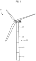
- Fig. 1 shows a wind turbine 10 with a tower 20, a nacelle and at least one rotor blade.
- the tower 20 comprising a plurality of tower sections 21, 22, 23 and 24.
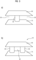
- Fig. 3a and Fig. 3b shows a front view of the spacer 40.
- the spacer 40 comprises a first plate 60, a second plate 70, at least one support element 80 and at least one opening 90.
- the first plat 60 and the second plate 70 are arranged parallel to each other and spaced apart to form at least one opening 90.
- the at least one support element 80 is arranged between the first plate 60 and the second plate 70 and coupled to both the first plate 60 and the second plate 70.
- the first plat 60 and the second plate 70 may have the same or similar size and may have squared, rectangular or trapezoidal shape.
- the spacer 40 may be made of concrete or a metallic material.
- the spacer 40 comprises only one support element 80 arranged between first plate 60 and the second plate 70 and may be place at the center of the plates, having the spacer 40 an I-shape and thereby having two openings 90, each opening 90 on each side of the support element 80.
- the spacer 40 comprises at least one support element 800.
- the support elements 80 may be arranged at the ends of the first plate 60 and second plate 70, forming an opening 90 between the support elements 80.
- the opening 90 s configured to allow workers to enter the interior of the tower.
- Some openings 90 may be configured for the passage of HV-cables.
- Fig. 4 shows a perspective view of the spacer 40.
- a guiding element 100 may be arranged at the first plate 60 for aligning the spacer 40 with the lower tower section 21 during installation.
- the guiding element 100 may be arranged at the middle of the first plate 60.
- the guiding element 100 may be configured to be aligned with the tower flange 30.
- the tip of the guiding element 100 may have a different color to identify the guiding element 100 faster.
- Fig. 5 shows a perspective view of a spacer with a guiding element 110 and forklift pockets 110.
- the spacer 40 may further comprise forklift pockets 110 for transporting the spacer 40 during installation.
- the forklift pockets 110 may be arranged at the outer side of the support elements 80.
- the forklift pockets 110 may have a square, rectangular or a certain shape to facilitate the spacer 40 to be gripped by the crane and prevent the spacer from slipping.
- the second plate 70 may have holes 130 and fastening means inserted in the holes 130 for coupling the second plate 70 with the frame 50.
- the holes 130 may have an elongated shape and may be placed at the corners of the second plate 70.
- the fastening means are semi-permanent joining means such as bolts, screws, pins, rivets, threads, studs, or other longitudinal pieces which can be used as fasteners.
- Fig. 6 shows a frame 50 with a plurality of tower spacers 40.
- a plurality of tower spacers 40 may be arranged in the frame 50 and may be arranged forming a circle to match with the lower tower section or to the tower flange.
- the plurality of tower spacers 40 may be arranged next to each other or may be arranged leaving a gap in between them.
Landscapes
- Engineering & Computer Science (AREA)
- Life Sciences & Earth Sciences (AREA)
- Sustainable Development (AREA)
- Sustainable Energy (AREA)
- Chemical & Material Sciences (AREA)
- Combustion & Propulsion (AREA)
- Mechanical Engineering (AREA)
- General Engineering & Computer Science (AREA)
- Wind Motors (AREA)
Abstract
A tower (20) for a wind turbine comprising a plurality of tower sections (21, 22, 23, 24), a spacer (40) and a frame (50) is provided. The spacer (40) configured for allowing access to the tower and the frame (50) for coupling the tower (20) to a foundation. The spacer (40) comprises a first plate (60), a second plate (70), and at least one support element (80) arranged between the first plate (60) and the second plate (70). The first plate (60) and second plate (70) spaced apart to form at least one opening (90) to allow workers to enter the interior of the tower (20).
Description
- The present invention relates to a tower for a wind turbine having a tower spacer between the lower part of the tower and the frame to allow workers to enter the interior of the tower.
- Wind turbine towers are typically designed with a door opening. Some offshore wind turbines assembly includes a transition piece with a door. However, there are some towers or transition pieces that do not include a door opening and the access must be arranged underneath the lower section of the tower or in the tower flange in such a case.
- A typical disadvantage of such known towers is that when maintenance is required, the tower must be lifted to allow workers to access to the interior of the tower and perform the maintenance tasks.
- It is therefore a goal of the present invention to provide a tower for a wind turbine with a spacer arranged between the frame and the lower space of the tower, in which the spacer has an opening configured for access to allow workers and the HV-cables to enter the interior of the tower, which overcomes the above-mentioned disadvantages.
- The object of the invention is achieved by the independent claims. The dependent claims describe advantageous developments and modifications of the invention.
- In accordance with the invention there is provided a tower for a wind turbine comprising a plurality of tower sections, a spacer for allowing access to the tower and a frame for coupling the tower to a foundation. The spacer is arranged between the frame and a lower tower section of the plurality of tower sections. The spacer comprises a first plate, a second plate and at least one support element. The first plate is coupled to a flange of the lower tower section and the second plate is coupled to the frame. The at least one support element is arranged between the first plate and the second plate and coupled to both the first plate and the second plate. The first plate and the second plate are spaced apart to form at least one opening, the opening is configured to allow workers to enter the interior of the tower.
- By having a spacer arranged between the frame and the lower tower section, the tower can be accessed easily by workers through the opening formed by the first and the second plate.
- The tower spacer allows to have a permanent access, preventing to lift the tower with a crane to access underneath the tower every time that the tower needs to be accessed e.g., due a maintenance task, which is a costly and complex operation.
- In an example, the spacer may comprise a plurality of support elements arranged between the first plate and the second plate. The support elements may be coupled to both the first plate and the second plate.
- In an example, the spacer may comprise a plurality of openings formed between the plurality of support elements.
- In an example, the at least one of the plurality of openings may be configured for the passage of HV-cables.
- Some openings may be assigned only for HV-cables and others only for worker access to prevent accidents, e.g., worker tripping over a cable.
- In an example, the tower may comprise a plurality of spacers arranged between the frame and the lower tower section.
- By having a plurality of spacers arranged between the frame and the lower tower section, there may be a plurality of access to the interior of the tower. Thereby, a worker may save time by entering the tower by the nearest access. In the same way, the HV-cables may be introduced into the nearest access, preventing surrounding the tower which may require longer cables.
- In an example, the spacer may further comprise a tower guiding element arranged at the first plate for aligning the spacer with the lower tower section during installation.
- In an example, the spacer may further comprise at least one forklift pocket for transporting the spacer during installation.
- By having a forklift pocket, the spacer can be easily and securely gripped by a crane, preventing the spacer from slipping.
- In an example, the first plate may comprise holes and fastening means inserted in the holes for coupling the first plate with the lower tower section.
- In an example, the second plate may comprise holes and fastening means inserted in the holes for coupling the second plate with the frame.
- In an example, the fastening means are semi-permanent joining means such as bolts, screws, pins, rivets, threads, studs, or other longitudinal pieces which can be used as fasteners.
- In a further aspect, a wind turbine comprising a generator, a foundation, a nacelle, and a tower is provided. The frame of the tower is coupled to the foundation and an upper tower section of the plurality of tower sections is coupled to the nacelle.
- Advantageous configurations and embodiments of the tower according to the invention follow from the claims dependent on claim 1 and claim 11 as well as the following description. The advantageous features of the tower and the wind turbine can generally be combined.
- Embodiments of the invention are now described, by way of example only, with reference to the accompanying drawings, of which:
- Fig.1
- shows a wind turbine;
- Fig. 2
- shows a tower of a wind turbine; and
- Fig. 3a and 3b
- shows a front view of a spacer; and
- Fig. 4
- shows a perspective view of a spacer; and
- Fig. 5
- shows a perspective view of a spacer with a guiding element and forklift pockets; and
- Fig. 6
- shows a frame with a plurality of tower spacers.
- The illustration in the drawings is in schematic form. It is noted that in different figures, similar or identical elements may be provided with the same reference signs.
-
Fig. 1 shows awind turbine 10 with atower 20, a nacelle and at least one rotor blade. Thetower 20 comprising a plurality oftower sections -
Fig. 2 shows atower 20 of a wind turbine. Thelower tower section 21 is connected to atower flange 30 or directly connected to aframe 50, which is for coupling thetower 20 to a foundation. At least onespacer 40 is arranged between theframe 50 and alower tower section 21 or thetower flange 30. A plurality of spacers may be arranged between theframe 50 and thelower tower section 21 or thetower flange 30. -
Fig. 3a and Fig. 3b shows a front view of thespacer 40. Thespacer 40 comprises afirst plate 60, asecond plate 70, at least onesupport element 80 and at least oneopening 90. Thefirst plat 60 and thesecond plate 70 are arranged parallel to each other and spaced apart to form at least oneopening 90. The at least onesupport element 80 is arranged between thefirst plate 60 and thesecond plate 70 and coupled to both thefirst plate 60 and thesecond plate 70. Thefirst plat 60 and thesecond plate 70 may have the same or similar size and may have squared, rectangular or trapezoidal shape. Thespacer 40 may be made of concrete or a metallic material. - In
Fig. 3a thespacer 40 comprises only onesupport element 80 arranged betweenfirst plate 60 and thesecond plate 70 and may be place at the center of the plates, having thespacer 40 an I-shape and thereby having twoopenings 90, each opening 90 on each side of thesupport element 80. - In
Fig.3b thespacer 40 comprises at least one support element 800. Thesupport elements 80 may be arranged at the ends of thefirst plate 60 andsecond plate 70, forming anopening 90 between thesupport elements 80. The opening 90 s configured to allow workers to enter the interior of the tower. - Some
openings 90 may be configured for the passage of HV-cables. -
Fig. 4 shows a perspective view of thespacer 40. A guidingelement 100 may be arranged at thefirst plate 60 for aligning thespacer 40 with thelower tower section 21 during installation. The guidingelement 100 may be arranged at the middle of thefirst plate 60. In case thetower 20 comprise atower flange 40, the guidingelement 100 may be configured to be aligned with thetower flange 30. The tip of the guidingelement 100 may have a different color to identify the guidingelement 100 faster. -
Fig. 5 shows a perspective view of a spacer with a guidingelement 110 and forklift pockets 110. Thespacer 40 may further comprise forklift pockets 110 for transporting thespacer 40 during installation. The forklift pockets 110 may be arranged at the outer side of thesupport elements 80. The forklift pockets 110 may have a square, rectangular or a certain shape to facilitate thespacer 40 to be gripped by the crane and prevent the spacer from slipping. - The
first plate 60 may haveholes 120 and fastening means inserted in theholes 120 for coupling thefirst plate 60 with thelower tower section 21 or to thetower flange 30. The first plate holes 120 may be distributed at the perimeter or at the corners of thefirst plate 60. - The
second plate 70 may haveholes 130 and fastening means inserted in theholes 130 for coupling thesecond plate 70 with theframe 50. Theholes 130 may have an elongated shape and may be placed at the corners of thesecond plate 70. The fastening means are semi-permanent joining means such as bolts, screws, pins, rivets, threads, studs, or other longitudinal pieces which can be used as fasteners. -
Fig. 6 shows aframe 50 with a plurality oftower spacers 40. A plurality oftower spacers 40 may be arranged in theframe 50 and may be arranged forming a circle to match with the lower tower section or to the tower flange. The plurality oftower spacers 40 may be arranged next to each other or may be arranged leaving a gap in between them. - Although the present invention has been described in detail with reference to the preferred embodiment, it is to be understood that the present invention is not limited by the disclosed examples, and that numerous additional modifications and variations could be made thereto by a person skilled in the art without departing from the scope of the invention.
- It should be noted that the use of "a" or "an" throughout this application does not exclude a plurality, and "comprising" does not exclude other steps or elements. Also elements described in association with different embodiments may be combined. It should also be noted that reference signs in the claims should not be construed as limiting the scope of the claims.
Claims (11)
- A tower (20) for a wind turbine (10) comprising a plurality of tower sections (21, 22, 23, 24), a spacer (40) for allowing access to the tower (20) and a frame (50) for coupling the tower (20) to a foundation,wherein the spacer (40) is arranged between the frame (50) and a lower tower section (21) of the plurality of tower sections (21, 22, 23, 24),wherein the spacer (40) comprises:- a first plate (60) coupled to a flange (30) of the lower tower section (21),- a second plate (70) coupled to the frame (50), and- at least one support element (80) arranged between the first plate (60) and the second plate (70) and coupled to both the first plate (60) and the second plate (70), characterized in thatthe first plate (60) and the second plate (70) are spaced apart to form at least one opening (90),wherein the opening (90) is configured to allow workers to enter the interior of the tower (20).
- The tower (20) according to claim 1, wherein the spacer (40) comprises a plurality of support elements (80) arranged between the first plate (60) and the second plate (70) and coupled to both the first plate (60) and the second plate (70) .
- The tower (20) according to claim 2, wherein the spacer (40) comprises a plurality of openings (90) formed between the plurality of support elements (80).
- The tower (20) according to claim 3, wherein at least one of the plurality of openings (90) is configured for the passage of HV-cables.
- The tower (20) according to any of the preceding claims, wherein said tower (20) comprises a plurality of spacers (40) arranged between the frame (50) and the lower tower section (21) .
- The tower (20) according to any of the preceding claims, wherein the spacer (40) further comprises a tower guiding element (100) arranged at the first plate (60) for aligning the spacer (40) with the lower tower section (21) during installation.
- The tower (20) according to any of the preceding claims, wherein the spacer (40) further comprises at least one forklift pocket (110) for transporting the spacer (40) during installation.
- The tower (20) according to any of the preceding claims, wherein the first plate (60) comprises holes (120) and fastening means inserted in the holes (120) for coupling the first plate (60) with the lower tower section (21).
- The tower (20) according to any of the preceding claims, wherein the second plate (70) comprises holes (130) and fastening means inserted in the holes (130) for coupling the second plate (70) with the frame (50).
- The tower (20) according to claim 8 or 9, wherein the fastening means are semi-permanent joining means such as bolts, screws, pins, rivets, threads, studs, or other longitudinal pieces which can be used as fasteners.
- A wind turbine (10) comprising a generator, a foundation, a nacelle and a tower (20) according to any of the claims 1 to 10, wherein the frame (50) of the tower (20) is coupled to the foundation and an upper tower section (24) of the plurality of tower sections (21, 22, 23, 24) is coupled to the nacelle.
Priority Applications (4)
| Application Number | Priority Date | Filing Date | Title |
|---|---|---|---|
| EP23195347.2A EP4520959A1 (en) | 2023-09-05 | 2023-09-05 | A tower for a wind turbine |
| EP24751652.9A EP4739906A1 (en) | 2023-09-05 | 2024-07-30 | A tower for a wind turbine |
| PCT/EP2024/071549 WO2025051450A1 (en) | 2023-09-05 | 2024-07-30 | A tower for a wind turbine |
| TW113133245A TWI920704B (en) | 2023-09-05 | 2024-09-03 | A tower for a wind turbine |
Applications Claiming Priority (1)
| Application Number | Priority Date | Filing Date | Title |
|---|---|---|---|
| EP23195347.2A EP4520959A1 (en) | 2023-09-05 | 2023-09-05 | A tower for a wind turbine |
Publications (1)
| Publication Number | Publication Date |
|---|---|
| EP4520959A1 true EP4520959A1 (en) | 2025-03-12 |
Family
ID=87934033
Family Applications (2)
| Application Number | Title | Priority Date | Filing Date |
|---|---|---|---|
| EP23195347.2A Withdrawn EP4520959A1 (en) | 2023-09-05 | 2023-09-05 | A tower for a wind turbine |
| EP24751652.9A Pending EP4739906A1 (en) | 2023-09-05 | 2024-07-30 | A tower for a wind turbine |
Family Applications After (1)
| Application Number | Title | Priority Date | Filing Date |
|---|---|---|---|
| EP24751652.9A Pending EP4739906A1 (en) | 2023-09-05 | 2024-07-30 | A tower for a wind turbine |
Country Status (2)
| Country | Link |
|---|---|
| EP (2) | EP4520959A1 (en) |
| WO (1) | WO2025051450A1 (en) |
Citations (3)
| Publication number | Priority date | Publication date | Assignee | Title |
|---|---|---|---|---|
| CN111306007A (en) * | 2020-04-09 | 2020-06-19 | 颜志成 | Fan tower drum connecting structure and construction method |
| CN114934881A (en) * | 2022-06-07 | 2022-08-23 | 西安科技大学 | Aerogenerator overhauls auxiliary device |
| CN115573871A (en) * | 2022-11-21 | 2023-01-06 | 中国船舶重工集团海装风电股份有限公司 | Frame module and installation method of offshore unit tower equipment for efficient construction |
Family Cites Families (4)
| Publication number | Priority date | Publication date | Assignee | Title |
|---|---|---|---|---|
| US7694476B2 (en) * | 2008-02-29 | 2010-04-13 | Structural Components Llc | Systems and methods for in-line base plate termination in monopole structures |
| CN208057316U (en) * | 2018-03-06 | 2018-11-06 | 中国电建集团华东勘测设计研究院有限公司 | A kind of Wind turbines steel reinforced concrete tower prestress wire Opposite direction connection flange arrangement |
| CN209115261U (en) * | 2018-10-29 | 2019-07-16 | 浙江中拓电力科技有限公司 | A kind of tower tube of offshore wind power generator levelling device |
| CN113217294B (en) * | 2021-06-25 | 2022-07-01 | 上海电气风电集团股份有限公司 | Tower bottom section structure, tower and wind driven generator |
-
2023
- 2023-09-05 EP EP23195347.2A patent/EP4520959A1/en not_active Withdrawn
-
2024
- 2024-07-30 WO PCT/EP2024/071549 patent/WO2025051450A1/en active Pending
- 2024-07-30 EP EP24751652.9A patent/EP4739906A1/en active Pending
Patent Citations (3)
| Publication number | Priority date | Publication date | Assignee | Title |
|---|---|---|---|---|
| CN111306007A (en) * | 2020-04-09 | 2020-06-19 | 颜志成 | Fan tower drum connecting structure and construction method |
| CN114934881A (en) * | 2022-06-07 | 2022-08-23 | 西安科技大学 | Aerogenerator overhauls auxiliary device |
| CN115573871A (en) * | 2022-11-21 | 2023-01-06 | 中国船舶重工集团海装风电股份有限公司 | Frame module and installation method of offshore unit tower equipment for efficient construction |
Also Published As
| Publication number | Publication date |
|---|---|
| WO2025051450A1 (en) | 2025-03-13 |
| TW202516106A (en) | 2025-04-16 |
| EP4739906A1 (en) | 2026-05-13 |
Similar Documents
| Publication | Publication Date | Title |
|---|---|---|
| EP2541047B1 (en) | Wind turbine assembling method and wind turbine assembled according to said method | |
| US8051627B2 (en) | Tower adapter, method of producing a tower foundation and tower foundation | |
| EP2207943B1 (en) | Tower structure and method of assembling | |
| US11072903B2 (en) | Equipment tower having a concrete plinth | |
| EP3211154B1 (en) | Manufacturing process of concrete towers for wind turbines | |
| US20200011302A1 (en) | Helicopter hoisting platform for wind driven power plant | |
| EP3786393A1 (en) | Movable module for hoisting telescopic towers and method for hoisting telescopic towers | |
| EP3118393B1 (en) | Anchoring means using a cable for a horizontal joint, and anchoring method using a cable for a horizontal joint | |
| WO2015169968A1 (en) | Reinforcement of an access-way to a tower | |
| US20100132278A1 (en) | Method and system for coupling a stair platform to a tower of a wind energy turbine | |
| WO2025051450A1 (en) | A tower for a wind turbine | |
| TWI920704B (en) | A tower for a wind turbine | |
| EP4345294A1 (en) | Concrete segment of a section of a tower of a wind turbine and adapter of a tower of a wind turbine tower | |
| US11873727B2 (en) | System and method for hoisting gas engine assemblies | |
| AU2023354384A1 (en) | Concrete segment of a section of a tower of a wind turbine and adapter of a tower of a wind turbine tower | |
| CN221318967U (en) | Tool for hoisting fan | |
| KR102621878B1 (en) | Vertical protective net assistant device | |
| CN222966597U (en) | An inflatable cabinet gas box convenient for hoisting | |
| CN220487257U (en) | A device for facing limit protection | |
| US20260132771A1 (en) | Concrete segment of a section of a tower of a wind turbine and adapter of a tower of a wind turbine tower | |
| CN223548908U (en) | Mixed tower installation operation platform | |
| US20230183041A1 (en) | Transport system for vertically transporting goods and persons on an above ground construction site | |
| WO2024068735A1 (en) | Concrete segment of a section of a tower of a wind turbine and adapter of a tower of a wind turbine tower | |
| Biegus et al. | Failure hazard and strengthening of roof in steel industrial building after explosion of electric furnace | |
| US20190242522A1 (en) | Connecting device for a wind turbine component |
Legal Events
| Date | Code | Title | Description |
|---|---|---|---|
| PUAI | Public reference made under article 153(3) epc to a published international application that has entered the european phase |
Free format text: ORIGINAL CODE: 0009012 |
|
| STAA | Information on the status of an ep patent application or granted ep patent |
Free format text: STATUS: THE APPLICATION HAS BEEN PUBLISHED |
|
| AK | Designated contracting states |
Kind code of ref document: A1 Designated state(s): AL AT BE BG CH CY CZ DE DK EE ES FI FR GB GR HR HU IE IS IT LI LT LU LV MC ME MK MT NL NO PL PT RO RS SE SI SK SM TR |
|
| STAA | Information on the status of an ep patent application or granted ep patent |
Free format text: STATUS: THE APPLICATION IS DEEMED TO BE WITHDRAWN |
|
| 18D | Application deemed to be withdrawn |
Effective date: 20250913 |