EP4520875A2 - Work machine - Google Patents
Work machine Download PDFInfo
- Publication number
- EP4520875A2 EP4520875A2 EP24196514.4A EP24196514A EP4520875A2 EP 4520875 A2 EP4520875 A2 EP 4520875A2 EP 24196514 A EP24196514 A EP 24196514A EP 4520875 A2 EP4520875 A2 EP 4520875A2
- Authority
- EP
- European Patent Office
- Prior art keywords
- electric motor
- work machine
- inverter unit
- unit
- battery unit
- Prior art date
- Legal status (The legal status is an assumption and is not a legal conclusion. Google has not performed a legal analysis and makes no representation as to the accuracy of the status listed.)
- Pending
Links
Images







Classifications
-
- E—FIXED CONSTRUCTIONS
- E02—HYDRAULIC ENGINEERING; FOUNDATIONS; SOIL SHIFTING
- E02F—DREDGING; SOIL-SHIFTING
- E02F9/00—Component parts of dredgers or soil-shifting machines, not restricted to one of the kinds covered by groups E02F3/00 - E02F7/00
- E02F9/08—Superstructures; Supports for superstructures
- E02F9/0841—Articulated frame, i.e. having at least one pivot point between two travelling gear units
-
- E—FIXED CONSTRUCTIONS
- E02—HYDRAULIC ENGINEERING; FOUNDATIONS; SOIL SHIFTING
- E02F—DREDGING; SOIL-SHIFTING
- E02F9/00—Component parts of dredgers or soil-shifting machines, not restricted to one of the kinds covered by groups E02F3/00 - E02F7/00
- E02F9/08—Superstructures; Supports for superstructures
- E02F9/0858—Arrangement of component parts installed on superstructures not otherwise provided for, e.g. electric components, fenders, air-conditioning units
- E02F9/0866—Engine compartment, e.g. heat exchangers, exhaust filters, cooling devices, silencers, mufflers, position of hydraulic pumps in the engine compartment
-
- E—FIXED CONSTRUCTIONS
- E02—HYDRAULIC ENGINEERING; FOUNDATIONS; SOIL SHIFTING
- E02F—DREDGING; SOIL-SHIFTING
- E02F9/00—Component parts of dredgers or soil-shifting machines, not restricted to one of the kinds covered by groups E02F3/00 - E02F7/00
- E02F9/08—Superstructures; Supports for superstructures
- E02F9/0858—Arrangement of component parts installed on superstructures not otherwise provided for, e.g. electric components, fenders, air-conditioning units
- E02F9/0883—Tanks, e.g. oil tank, urea tank, fuel tank
-
- E—FIXED CONSTRUCTIONS
- E02—HYDRAULIC ENGINEERING; FOUNDATIONS; SOIL SHIFTING
- E02F—DREDGING; SOIL-SHIFTING
- E02F9/00—Component parts of dredgers or soil-shifting machines, not restricted to one of the kinds covered by groups E02F3/00 - E02F7/00
- E02F9/20—Drives; Control devices
- E02F9/2058—Electric or electro-mechanical or mechanical control devices of vehicle sub-units
- E02F9/2062—Control of propulsion units
- E02F9/207—Control of propulsion units of the type electric propulsion units, e.g. electric motors or generators
-
- E—FIXED CONSTRUCTIONS
- E02—HYDRAULIC ENGINEERING; FOUNDATIONS; SOIL SHIFTING
- E02F—DREDGING; SOIL-SHIFTING
- E02F9/00—Component parts of dredgers or soil-shifting machines, not restricted to one of the kinds covered by groups E02F3/00 - E02F7/00
- E02F9/20—Drives; Control devices
- E02F9/2058—Electric or electro-mechanical or mechanical control devices of vehicle sub-units
- E02F9/2091—Control of energy storage means for electrical energy, e.g. battery or capacitors
Definitions
- the present invention relates to a work machine including an electric motor.
- a work machine including a front vehicle body to which front wheels and a work implement are attached, a rear vehicle body, and an electric motor mounted on the rear vehicle body (for example, see Patent Document 1).
- a work machine motor grader including an electric motor as a power source is known (for example, see Patent Document 2).
- This work machine is provided with a plurality of drive batteries that are power supplies of the electric motors.
- the electric motor is used to drive at least an axle (rear wheel) and a working unit (work implement).
- the work machine includes an inverter unit (inverter), a battery unit (battery), and a charging device.
- the inverter unit converts electric power stored in the battery unit and supplies the converted electric power to the electric motor.
- the charging device is a device for charging the battery unit.
- the charging device has a connector connected to an external power supply, and charges the battery unit with direct-current power.
- the driving force of the working unit may be insufficient when the traveling load increases, or the driving force of the axle may be insufficient when the load of the working unit increases.
- the electric motor and the inverter unit depending on the arrangement of the electric motor and the inverter unit, for example, it may be difficult to route a cable that connects the electric motor and the inverter unit, or miniaturization of the work machine may be hindered.
- An object of the present invention is to provide a work machine in which an insufficient driving force of an axle and a working unit is less likely to occur, or a work machine in which an appropriate arrangement of an electric motor and an inverter unit is easily achieved.
- a work machine includes a machine body frame, a first electric motor, a second electric motor, and an oil tank.
- An axle is mounted on the machine body frame.
- the first electric motor generates power for driving the axle.
- the second electric motor drives the hydraulic pump that feeds hydraulic oil to the hydraulic actuator.
- the oil tank stores the hydraulic oil.
- the first electric motor is located between the second electric motor and the oil tank in a plan view.
- a work machine includes a machine body frame, an electric motor, an inverter unit, and a power transmission mechanism.
- An axle is mounted on the machine body frame.
- the electric motor generates power for driving the axle.
- the inverter unit drives the electric motor by electric power supplied from a battery unit.
- the power transmission mechanism transmits power generated by the electric motor to the axle. At least a part of the power transmission mechanism is located between the electric motor and the inverter unit in a plan view.
- a work machine 3 includes, in a machine body 30, a traveling unit 31, a driving unit 32, and a working unit 33.
- the "work machine” referred to in the present disclosure means various types of work machines and is, for example, a work vehicle such as a wheel loader, a backhoe (including a hydraulic excavator, a mini excavator, and the like), and a carrier.
- the work machine 3 includes the working unit 33 that is configured to be able to perform one or more works including at least a loading work.
- the work machine 3 is not limited to a "vehicle” and may be, for example, a working vessel, a working flying object such as a drone or a multicopter, or the like.
- the work machine 3 is not limited to a construction machine (construction equipment), but may also be an agricultural machine (agricultural equipment), such as a rice transplanter, a tractor, or a combined harvester, for example.
- an agricultural machine agricultural equipment
- a rice transplanter a rice transplanter
- a tractor a tractor
- a combined harvester for example.
- the work machine 3 is a riding-type wheel loader which can perform a transport work, an excavation work, a ground leveling work, a suspending work or the like in addition to the loading work as the works will be explained as an example.
- a vertical direction in a usable state of the work machine 3 will be defined as an up-down direction D1 for convenience of description.
- a front-rear direction D2 and a left-right direction D3 are defined with reference to a direction as viewed from a user (operator) on board (the driving unit 32 of) the work machine 3.
- each of the directions used in this embodiment is a direction that is defined with the machine body 30 of the work machine 3 as a reference, and a direction in which the machine body 30 moves in a forward travel of the work machine 3 is a "front", and a direction in which the machine body 30 moves in a reverse travel of the work machine 3 is a "rear".
- a direction in which the machine body 30 moves at a right turn of the work machine 3 is a "right”
- a direction in which the machine body 30 moves at a left turn of the work machine 3 is a "left”.
- these directions are not meant to limit a direction in which the work machine 3 is used (direction during use).
- the working unit 33 is driven in accordance with an operation of a user (operator) on board the driving unit 32 and performs a work such as a loading work.
- the traveling unit 31 has a traveling function, and is so configured as to be capable of traveling (including swiveling) on the ground.
- the traveling unit 31 includes, for example, a pair of left and right front wheels 311 and a pair of left and right rear wheels 312.
- the traveling unit 31 further includes a steering cylinder 313 (see FIG. 3 ) for steering.
- the machine body 30 is of a center-folding type and is configured in such a manner that the machine body 30 is folded at a connecting portion provided at a position between the front wheels 311 and the rear wheels 312.
- the machine body 30 travels while turning to the right direction by being driven forward by the traveling unit 31.
- the front portion 301 of the machine body 30 where the front wheels 311 are provided is bent to the left with respect to the rear portion 302 where the rear wheels 312 are provided
- the machine body 30 travels while turning to the left direction by being driven forward by the traveling unit 31.
- the steering of the traveling unit 31 as above is performed by the front portion 301 of the machine body 30 driven to swing (rotate in both directions) about the connecting portion by the steering cylinder 313 in conjunction with the operation of a steering wheel of an operation device.
- the work machine 3 drives the axle 34 of the traveling unit 31 and the hydraulic pump 11 by separate electric motors (the first electric motor 41 and the second electric motor 42).
- the first electric motor 41 may be simply referred to as an "electric motor 41".
Landscapes
- Engineering & Computer Science (AREA)
- Mining & Mineral Resources (AREA)
- Civil Engineering (AREA)
- General Engineering & Computer Science (AREA)
- Structural Engineering (AREA)
- Power Engineering (AREA)
- Operation Control Of Excavators (AREA)
- Component Parts Of Construction Machinery (AREA)
Abstract
Description
- The present invention relates to a work machine including an electric motor.
- As a related art, there is known a work machine (wheel loader) including a front vehicle body to which front wheels and a work implement are attached, a rear vehicle body, and an electric motor mounted on the rear vehicle body (for example, see Patent Document 1). Further, a work machine (motor grader) including an electric motor as a power source is known (for example, see Patent Document 2).
- This work machine is provided with a plurality of drive batteries that are power supplies of the electric motors. The electric motor is used to drive at least an axle (rear wheel) and a working unit (work implement). Further, the work machine includes an inverter unit (inverter), a battery unit (battery), and a charging device. The inverter unit converts electric power stored in the battery unit and supplies the converted electric power to the electric motor. The charging device is a device for charging the battery unit. The charging device has a connector connected to an external power supply, and charges the battery unit with direct-current power.
-
- Patent Document 1:
Japanese Unexamined Patent Application Publication No. 2012-201187 - Patent Document 2:
Japanese Unexamined Patent Application Publication No. 2021-055359 - In the above-described related art, since one electric motor is used to drive the axle and the work implement, for example, the driving force of the working unit may be insufficient when the traveling load increases, or the driving force of the axle may be insufficient when the load of the working unit increases. Further, in the above-described related art, depending on the arrangement of the electric motor and the inverter unit, for example, it may be difficult to route a cable that connects the electric motor and the inverter unit, or miniaturization of the work machine may be hindered.
- An object of the present invention is to provide a work machine in which an insufficient driving force of an axle and a working unit is less likely to occur, or a work machine in which an appropriate arrangement of an electric motor and an inverter unit is easily achieved.
- A work machine according to one aspect of the present invention includes a machine body frame, a first electric motor, a second electric motor, and an oil tank. An axle is mounted on the machine body frame. The first electric motor generates power for driving the axle. The second electric motor drives the hydraulic pump that feeds hydraulic oil to the hydraulic actuator. The oil tank stores the hydraulic oil. The first electric motor is located between the second electric motor and the oil tank in a plan view. Further, a work machine according to one aspect of the present invention includes a machine body frame, an electric motor, an inverter unit, and a power transmission mechanism. An axle is mounted on the machine body frame. The electric motor generates power for driving the axle. The inverter unit drives the electric motor by electric power supplied from a battery unit. The power transmission mechanism transmits power generated by the electric motor to the axle. At least a part of the power transmission mechanism is located between the electric motor and the inverter unit in a plan view.
- According to the present invention, it is possible to provide a work machine in which an insufficient driving force of an axle and a working unit is less likely to occur, or a work machine in which an appropriate arrangement of an electric motor and an inverter unit is easily achieved.
-
-
FIG. 1 is a schematic perspective view illustrating an overall configuration of a work machine according to a first embodiment, as viewed from the left front. -
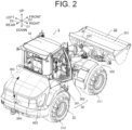
FIG. 2 is a schematic perspective view illustrating the overall configuration of the work machine according to the first embodiment, as viewed from the right rear. -
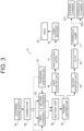
FIG. 3 is a schematic block diagram illustrating the work machine according to the first embodiment. -
FIG. 4 is a schematic plan view illustrating an internal structure of the work machine according to the first embodiment. -
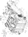
FIG. 5 is a schematic perspective view illustrating an internal structure of a rear section of the work machine according to the first embodiment, as viewed from the right rear. -
FIG. 6 is a schematic perspective view illustrating the internal structure of the rear section of the work machine according to the first embodiment, which is taken along the line A1 - A1 inFIG. 4 and viewed from the right rear. -
FIG. 7 is a rear view illustrating the internal structure of the rear section of the work machine according to the first embodiment, which is taken along the line A1 - A1 inFIG. 4 . -
FIG. 8 is a schematic perspective view illustrating the internal structure of the rear section of the work machine according to the first embodiment, as viewed from the right rear. -
FIG. 9 is a schematic perspective view illustrating the internal structure of the rear section of the work machine according to the first embodiment, as viewed from the left front. -
FIG. 10 is a schematic perspective view illustrating a battery unit of the work machine according to the first embodiment. -
FIG. 11 is a schematic left side view illustrating the internal structure of the rear section of the work machine according to the first embodiment. -
FIG. 12 is a schematic perspective view illustrating the internal structure of the rear section of the work machine according to the first embodiment, as viewed from the right rear. -
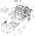
FIG. 13 is a schematic perspective view illustrating the internal structure of the rear section of the work machine according to the first embodiment, as viewed from the left front. -
FIG. 14 is a schematic perspective view illustrating a state where the battery unit of the rear section of the work machine according to the first embodiment is removed, as viewed from the right rear. -
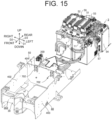
FIG. 15 is a schematic perspective view illustrating a state where the battery unit of the rear section of the work machine according to the first embodiment is removed, as viewed from the left front. -
FIG. 16 is a schematic perspective view illustrating the internal structure of the rear section of the work machine according to the first embodiment, as viewed from the left front. -
FIG. 17 is a schematic perspective view illustrating the internal structure of the rear section of the work machine according to the first embodiment, as viewed from the right front. -
FIG. 18 is a schematic perspective view illustrating the internal structure of the rear section of the work machine according to the first embodiment, as viewed obliquely from the lower right front side. -
FIG. 19 is a schematic front view illustrating the internal structure of the rear section of the work machine according to the first embodiment. -
FIG. 20 is a schematic plan view illustrating the internal structure of the rear section of the work machine according to the first embodiment. - Hereinafter, embodiments of the present invention will be described with reference to the accompanying drawings. The following embodiments are examples that embody the present invention, and do not intend to limit the technical scope of the present invention.
- As illustrated in
FIGs. 1 and2 , awork machine 3 according to the present embodiment includes, in amachine body 30, atraveling unit 31, adriving unit 32, and a workingunit 33. - The "work machine" referred to in the present disclosure means various types of work machines and is, for example, a work vehicle such as a wheel loader, a backhoe (including a hydraulic excavator, a mini excavator, and the like), and a carrier. The
work machine 3 includes the workingunit 33 that is configured to be able to perform one or more works including at least a loading work. Thework machine 3 is not limited to a "vehicle" and may be, for example, a working vessel, a working flying object such as a drone or a multicopter, or the like. Moreover, thework machine 3 is not limited to a construction machine (construction equipment), but may also be an agricultural machine (agricultural equipment), such as a rice transplanter, a tractor, or a combined harvester, for example. In the present embodiment, unless otherwise specified, a case where thework machine 3 is a riding-type wheel loader which can perform a transport work, an excavation work, a ground leveling work, a suspending work or the like in addition to the loading work as the works will be explained as an example. - Further, in this embodiment, a vertical direction in a usable state of the
work machine 3 will be defined as an up-down direction D1 for convenience of description. Furthermore, a front-rear direction D2 and a left-right direction D3 are defined with reference to a direction as viewed from a user (operator) on board (the drivingunit 32 of) thework machine 3. In other words, each of the directions used in this embodiment is a direction that is defined with themachine body 30 of thework machine 3 as a reference, and a direction in which themachine body 30 moves in a forward travel of thework machine 3 is a "front", and a direction in which themachine body 30 moves in a reverse travel of thework machine 3 is a "rear". Similarly, a direction in which themachine body 30 moves at a right turn of thework machine 3 is a "right", and a direction in which themachine body 30 moves at a left turn of thework machine 3 is a "left". However, these directions are not meant to limit a direction in which thework machine 3 is used (direction during use). - In the present embodiment, as described above, such a case that the
work machine 3 is a riding-type wheel loader is assumed, and thus the workingunit 33 is driven in accordance with an operation of a user (operator) on board the drivingunit 32 and performs a work such as a loading work. - The traveling
unit 31 has a traveling function, and is so configured as to be capable of traveling (including swiveling) on the ground. The travelingunit 31 includes, for example, a pair of left and rightfront wheels 311 and a pair of left and rightrear wheels 312. The travelingunit 31 further includes a steering cylinder 313 (seeFIG. 3 ) for steering. - In the
work machine 3 as a wheel loader, themachine body 30 is of a center-folding type and is configured in such a manner that themachine body 30 is folded at a connecting portion provided at a position between thefront wheels 311 and therear wheels 312. - That is, in a state where a
front portion 301 of themachine body 30 where thefront wheels 311 are provided is bent to the right with respect to arear portion 302 where therear wheels 312 are provided, themachine body 30 travels while turning to the right direction by being driven forward by the travelingunit 31. On the other hand, in a state where thefront portion 301 of themachine body 30 where thefront wheels 311 are provided is bent to the left with respect to therear portion 302 where therear wheels 312 are provided, themachine body 30 travels while turning to the left direction by being driven forward by the travelingunit 31. The steering of the travelingunit 31 as above is performed by thefront portion 301 of themachine body 30 driven to swing (rotate in both directions) about the connecting portion by thesteering cylinder 313 in conjunction with the operation of a steering wheel of an operation device. - The driving
unit 32 where the user is on board is provided above the travelingunit 31. Specifically, the drivingunit 32 is disposed on a portion on the rear side of the connecting portion in themachine body 30, that is, on arear portion 302 where therear wheels 312 are provided. - The working
unit 33 is configured to be able to perform works including a loading work. The workingunit 33 has abucket 331, anarm 332, and the like. The workingunit 33 further has hydraulic actuators (including thehydraulic cylinders 333, and the like) for driving each part. - The
bucket 331 is a type of attachment (work tool) that is attached to themachine body 30 of thework machine 3, and is made up of any tool selected from a plurality of types of attachments depending on the type of work to be performed. - The
bucket 331 is, as an example, removably attached to themachine body 30 and replaced in accordance with the contents of a work. The attachment for thework machine 3 includes various implements such as a fork, a snow blade, and a plow and the like in addition to thebucket 331, for example. - The
arm 332 is rotatably attached to themachine body 30. Specifically, thearm 332 is supported rotatably about a rotary shaft along a horizontal direction. Thebucket 331 is attached to a distal end of thearm 332. - The
work machine 3 has ahood 303 and acounterweight 304 in therear portion 302 of themachine body 30. - The
hood 303 is located behind the drivingunit 32 and is configured to cover an engine room 300 (seeFIG. 4 ) from above. Thehood 303 can be opened and closed as indicated by a broken line arrow inFIG. 2 by rotating about a rotary shaft provided at a front end portion of thehood 303. Theengine room 300 is exposed in a state where thehood 303 is opened. - The
counterweight 304 is located below thehood 303 in rear end portion (back surface) of (therear portion 302 of) themachine body 30. Thecounterweight 304 is removably attached to themachine body 30. - The
work machine 3 according to the present embodiment is an electric work machine including an electric motor 41 (seeFIG. 3 ) as a power source. Theelectric motor 41 is an electric motor driven by receiving electric power supply. Thework machine 3 according to the present embodiment drives an axle 34 (seeFIG. 3 ) of the travelingunit 31 by power generated by theelectric motor 41. - Further, the
work machine 3 according to the present embodiment further includes a second electric motor 42 (seeFIG. 3 ) in addition to the electric motor (first electric motor) 41 for driving the travelingunit 31. The secondelectric motor 42 is an electric motor driven by receiving electric power supply. The secondelectric motor 42 drives the hydraulic pump 11 (seeFIG. 3 ), and causes thehydraulic pump 11 to supply hydraulic oil to hydraulic actuators (including thesteering cylinder 313, thehydraulic cylinder 333 of the workingunit 33, and the like) of various parts of themachine body 30, thereby driving themachine body 30. - The first
electric motor 41 and the secondelectric motor 42 are operated by electric power supplied from a battery unit 50 (seeFIG. 3 ). Therefore, themachine body 30 is provided with a power supply port 305 (seeFIG. 1 ) for charging thebattery unit 50. In the present embodiment, as an example, thepower supply port 305 is disposed at a position on the left side surface of themachine body 30 and above therear wheels 312. - The configuration of the drive system including the first
electric motor 41 and the secondelectric motor 42 will be described in detail in the section "[2] Drive System". - Further, in addition to the above-described configuration, the
machine body 30 further includes a detector (including a sensor, a camera, and the like) for monitoring the periphery of the control system, display device, operation device,machine body 30, a sound outputter, a communication terminal, a fuel tank, a battery and the like. Furthermore, themachine body 30 includes sensors for monitoring the operation state of themachine body 30, such as a fuel residual-quantity gauge, a cooling-water temperature sensor, a hydraulic-oil temperature sensor, a rotation number meter for measuring the number of engine rotations, a speedometer for measuring a traveling speed, an hour meter for measuring an operating time and the like. - The control system mainly includes a computer system including one or more processors such as a central processing unit (CPU) and one or more memories such as a read only memory (ROM) and a random access memory (RAM), and performs various types of processing (information processing). In the present embodiment, the control system is an integrated controller that controls the
entire work machine 3, and includes an electronic control unit (ECU), for example. - The display device is disposed in the driving
unit 32 of themachine body 30, and is a user interface that accepts an operation input by the user (the operator) and outputs various types of information to the user. The display device accepts various operations from the user by outputting an electrical signal that corresponds to the user's operation. - The operation device is disposed in the driving
unit 32 of themachine body 30 and accepts an operation input by the user (operator). In the present embodiment, as an example, the operation device includes an operation lever, a steering wheel, and the like. The user (operator) on board the drivingunit 32 of themachine body 30 operates the operation device to control thework machine 3. - Next, a configuration of a drive system for driving each part of the
work machine 3 according to the present embodiment will be described with reference toFIGs. 3 and4 . InFIG. 3 , a flow of an electric signal for control (weak electric system) is indicated by a broken line arrow, a flow of electric power (strong electric system) is indicated by a solid line arrow, and a flow of power (including hydraulic pressure) is indicated by a one dot chain line arrow. - As described above, the
work machine 3 is an electric work machine including the electric motor (first electric motor) 41 as a power source. In the present embodiment, in particular, thework machine 3 includes two electric motors, that is, the firstelectric motor 41 that generates power for driving theaxle 34 of the travelingunit 31, and the secondelectric motor 42 that drives thehydraulic pump 11 that feeds hydraulic oil to the hydraulic actuators. - That is, the
work machine 3 drives theaxle 34 of the travelingunit 31 and thehydraulic pump 11 by separate electric motors (the firstelectric motor 41 and the second electric motor 42). In the present disclosure, of the firstelectric motor 41 and the secondelectric motor 42, the firstelectric motor 41 may be simply referred to as an "electric motor 41". - The traveling
unit 31 further includes theaxle 34 for driving thefront wheels 311 and therear wheels 312, thepower transmission mechanism 35, thesteering cylinder 313, and the like. Thepower transmission mechanism 35 transmits power generated by theelectric motor 41 to theaxle 34. That is, the power generated by the firstelectric motor 41 is transmitted to theaxle 34 via thepower transmission mechanism 35. - Meanwhile, the
steering cylinder 313 is an example of the hydraulic actuators that operate by receiving a supply of hydraulic oil from thehydraulic pump 11, and is indirectly driven by the secondelectric motor 42. Further, thehydraulic cylinder 333 of the workingunit 33 is also an example of the hydraulic actuators that operate by receiving the supply of the hydraulic oil from thehydraulic pump 11, and the hydraulic oil from thehydraulic pump 11 is also supplied to thehydraulic cylinder 333. - In the present embodiment, as an example, the first
electric motor 41 is an alternating-current motor that is driven by alternating-current power (alternating-current voltage) supplied from thefirst inverter unit 43. Similarly, the secondelectric motor 42 is an alternating-current motor that is driven by alternating-current power (alternating-current voltage) supplied from thesecond inverter unit 44. - That is, as illustrated in
FIG. 3 , thework machine 3 further includes thefirst inverter unit 43 for driving the firstelectric motor 41 and thesecond inverter unit 44 that drives the secondelectric motor 42. Thefirst inverter unit 43 drives the electric motor (first electric motor) 41 by electric power supplied from thebattery unit 50. Thesecond inverter unit 44 drives the secondelectric motor 42 by electric power supplied from thebattery unit 50. - The
first inverter unit 43 includes a power conversion circuit that converts direct-current power into alternating-current power, converts the direct-current power (direct-current voltage) output from thebattery unit 50 into alternating-current power (alternating-current voltage), and outputs the alternating-current power to the firstelectric motor 41. Accordingly, the firstelectric motor 41 including an alternating-current motor operates in accordance with the alternating-current power supplied from thefirst inverter unit 43. - Similarly, the
second inverter unit 44 includes a power conversion circuit that converts direct-current power into alternating-current power, converts the direct-current power (direct-current voltage) output from thebattery unit 50 into alternating-current power (alternating-current voltage), and outputs the alternating-current power to the secondelectric motor 42. Accordingly, the secondelectric motor 42 including an alternating-current motor operates in accordance with the alternating-current power supplied from thesecond inverter unit 44. - That is, the
work machine 3 drives the firstelectric motor 41 and the secondelectric motor 42 by separate inverter units (thefirst inverter unit 43 and the second inverter unit 44). In the present disclosure, of thefirst inverter unit 43 and thesecond inverter unit 44, thefirst inverter unit 43 may be simply referred to as an "inverter unit 43". - As illustrated in
FIG. 3 , thework machine 3 further includes thebattery unit 50, afirst charger 51, asecond charger 52, a chargingcontroller 53, and apower distributor 54. - The
battery unit 50 is a power storage device that stores electric energy, and is used as a supply source (power supply) of electric power to at least the firstelectric motor 41 and the secondelectric motor 42. Thebattery unit 50 is provided separately from an auxiliary battery 36 (seeFIG. 4 ) which will be described below, and is configured by combining a plurality of large-capacity secondary batteries (storage batteries) such as lithium ion batteries, for example. - The
first charger 51 and thesecond charger 52 are chargers for charging thebattery unit 50. Thefirst charger 51 charges thebattery unit 50 with electric power supplied from anexternal power supply 55. Similarly, thesecond charger 52 charges thebattery unit 50 with the electric power supplied from theexternal power supply 55. - The
first charger 51 and thesecond charger 52 are electrically connected to aconnector 56 provided in thepower supply port 305. When a system power supply (alternating current power supply) serving as theexternal power supply 55 is electrically connected to theconnector 56 of thepower supply port 305 using a charging cable, thefirst charger 51 and thesecond charger 52 are electrically connected to theexternal power supply 55 via theconnector 56. In this state, each of thefirst charger 51 and thesecond charger 52 charges thebattery unit 50 with electric power supplied from theexternal power supply 55. - In the present embodiment, as an example, each of the
first charger 51 and thesecond charger 52 includes a conversion circuit (converter) that converts an alternating-current voltage into a direct-current voltage. Each of thefirst charger 51 and thesecond charger 52 converts an alternating-current voltage applied from theexternal power supply 55 into a direct-current voltage and supplies the direct-current voltage to thebattery unit 50, thereby charging thebattery unit 50. - Here, the
first charger 51 can charge thebattery unit 50 by itself, and thesecond charger 52 can charge thebattery unit 50 together with thefirst charger 51. Thefirst charger 51 and thesecond charger 52 are electrically connected in parallel to thebattery unit 50, and when charging is performed by both thefirst charger 51 and thesecond charger 52, it is possible to charge thebattery unit 50 with a larger current than when charging is performed by thefirst charger 51 alone. - In short, the
work machine 3 according to the present embodiment has at least two charging modes of a "normal charging mode" and a "quick charging mode" as the charging mode of thebattery unit 50. The "normal charging mode" is a charging mode in which thebattery unit 50 is charged by thefirst charger 51 alone. The "quick charging mode" is a charging mode in which thebattery unit 50 is charged by both thefirst charger 51 and thesecond charger 52. Therefore, in the "quick charging mode", charging of thebattery unit 50 can be completed in a shorter time than in the "normal charging mode". - The charging
controller 53 controls thefirst charger 51 and thesecond charger 52. Specifically, the chargingcontroller 53 outputs a control signal to each of thefirst charger 51 and thesecond charger 52 to switch at least each of thefirst charger 51 and thesecond charger 52 between operation and stop. That is, the chargingcontroller 53 can switch the charging mode of thebattery unit 50 between the normal charging mode in which charging is performed by thefirst charger 51 alone and the quick charging mode in which charging is performed by thefirst charger 51 and thesecond charger 52. - The
power distributor 54 is a device that distributes electric power from thebattery unit 50 to a plurality of electric loads. Thepower distributor 54 is a power distribution unit (PDU), and distributes electric power from thebattery unit 50 to at least thefirst inverter unit 43 and thesecond inverter unit 44. - That is, the
battery unit 50, thefirst inverter unit 43, and thesecond inverter unit 44 are electrically connected to thepower distributor 54. Thepower distributor 54 supplies direct-current power (direct-current voltage) output from thebattery unit 50 during discharging of thebattery unit 50 to thefirst inverter unit 43 and thesecond inverter unit 44. Accordingly, thefirst inverter unit 43 and thesecond inverter unit 44 can be operated to drive the firstelectric motor 41 and the secondelectric motor 42. -
FIG. 4 is a plan view of thework machine 3 in which illustrations of exterior materials including a fender, a mirror, a direction indicator, a body, thehood 303, thecounterweight 304, and the like, the drivingunit 32, thebucket 331, thefront wheels 311, therear wheels 312, and the like are omitted. As illustrated inFIG. 4 , thework machine 3 includes arear axle 34 provided in therear portion 302 of themachine body 30, and afront axle 37 provided in thefront portion 301 of themachine body 30. - The
rear wheels 312 are attached to therear axle 34, and therear wheels 312 rotate when therear axle 34 is driven. Thefront wheels 311 are attached to thefront axle 37, and thefront wheels 311 rotate when therear axle 34 is driven. In the present disclosure, of therear axle 34 and thefront axle 37, therear axle 34 may be simply referred to as an "axle 34". - In the present embodiment, the first
electric motor 41 and thepower transmission mechanism 35 are mounted on therear portion 302 of themachine body 30 together with the axle (rear axle) 34. Thefront axle 37 disposed in thefront portion 301 is connected to thepower transmission mechanism 35 disposed in therear portion 302 by ashaft 38. That is, the power generated by the firstelectric motor 41 is transmitted to thefront axle 37 via thepower transmission mechanism 35 and theshaft 38. - Further, the devices of the drive system such as the second
electric motor 42, thefirst inverter unit 43, thesecond inverter unit 44, thebattery unit 50, thefirst charger 51, thesecond charger 52, the chargingcontroller 53, and thepower distributor 54 are also disposed in therear portion 302 similarly to the firstelectric motor 41 and the like. In the present embodiment, the secondelectric motor 42 and thehydraulic pump 11 are integrated (seeFIG. 4 ). Therefore, thehydraulic pump 11 is also disposed in therear portion 302 similarly to the firstelectric motor 41 and the like. - In the
rear portion 302 of themachine body 30, anengine room 300 is formed as a space for accommodating these devices of the drive system. The specific arrangement and the like of these devices of the drive system in theengine room 300 will be described in the section "[3] Configuration of Engine Room". - According to the drive system described above, the
work machine 3 can operate using electric power stored in thebattery unit 50 in a state where thebattery unit 50 is charged. That is, thework machine 3 drives theaxle 34 of the travelingunit 31 by the power generated by the firstelectric motor 41. Further, thework machine 3 drives thehydraulic pump 11 by the power generated by the secondelectric motor 42, and supplies the hydraulic oil from thehydraulic pump 11 to thesteering cylinder 313 which is an example of the hydraulic actuators. Accordingly, thework machine 3 can operate the traveling unit 31 (including theaxle 34 and the steering cylinder 313) to travel (including turning) on the ground. - Further, the
work machine 3 drives thehydraulic pump 11 by the power generated by the secondelectric motor 42, and supplies the hydraulic oil from thehydraulic pump 11 to thehydraulic cylinder 333 of the workingunit 33, which is an example of the hydraulic actuators. Accordingly, for example, when the hydraulic oil is supplied to thehydraulic cylinder 333 serving as the bucket cylinder, thework machine 3 operates the workingunit 33 in such a manner that the holding and returning by thebucket 331 is performed. Further, when the hydraulic oil is supplied to thehydraulic cylinder 333 serving as a boom cylinder (lift cylinder), thework machine 3 operates the workingunit 33 in such a manner that thebucket 331 is raised and lowered by the up and down movement of thearm 332. - In this way, the
work machine 3 can drive the firstelectric motor 41 and the secondelectric motor 42 by the electric power stored in thebattery unit 50, and can drive each part of thework machine 3 including the travelingunit 31 and the workingunit 33. - Next, a configuration in the
engine room 300 of thework machine 3 according to the present embodiment will be described with reference toFIGs. 5 to 20 . InFIGs. 5 to 20 , of thefront portion 301 and therear portion 302 of themachine body 30, only therear portion 302 is illustrated, and illustrations of components irrelevant to the description of theengine room 300, such as the drivingunit 32, the workingunit 33, and therear wheels 312, are omitted as appropriate. - As illustrated in
FIGs. 5 to 8 , thework machine 3 has amachine body frame 40 constituting a framework of themachine body 30 in therear portion 302 of themachine body 30.FIG. 5 is a schematic perspective view of therear portion 302 of thework machine 3, in which exterior materials including the fender, the body, thehood 303, thecounterweight 304, and the like are indicated by imaginary lines (two dot chain lines).FIGs. 6 and7 are a schematic perspective view and a rear view, respectively, of therear portion 302 of thework machine 3, taken along the line A1 to A1 inFIG. 4 .FIG. 8 is a schematic perspective view of therear portion 302 of thework machine 3, in which exterior materials including the fender, the body, thehood 303, thecounterweight 304, and the like are omitted. - The
machine body frame 40 includes abottom plate 401, aright side plate 402, and aleft side plate 403. Themachine body frame 40 is made of, for example, metal. Thebottom plate 401 is formed in a rectangular shape having a length in the front-rear direction D2 in a plan view. Theright side plate 402 is a plate-shaped member rising upward from the right end edge of thebottom plate 401, and theleft side plate 403 is a plate-shaped member rising upward from the left end edge of thebottom plate 401. - The devices of the drive system accommodated in the
engine room 300 are directly or indirectly fixed to themachine body frame 40. Further, most of the devices of the drive system except for thepower distributor 54 and the like are disposed at a position above thebottom plate 401 and between theright side plate 402 and theleft side plate 403 in the left-right direction D3. - Specifically, the
battery unit 50 that supplies electric power to theelectric motor 41 is disposed in a region surrounded by thebottom plate 401, theright side plate 402, and theleft side plate 403 in a state of being placed on thebottom plate 401 of themachine body frame 40. - Here, the
work machine 3 is provided with acooling device 6 for cooling thebattery unit 50. Thecooling device 6 is an air-cooling type cooling device that cools thebattery unit 50 by passing an airflow between afirst opening portion 601 and asecond opening portion 602 formed on both sides of theengine room 300 in the left-right direction D3. Further, in theengine room 300, an electrical device (as an example, the power distributor 54) different from thebattery unit 50 is disposed in an air-cooled space Sp1 cooled by thecooling device 6. - That is, the
work machine 3 according to the present embodiment includes thebattery unit 50, thecooling device 6, and the electrical device (as an example, the power distributor 54). Thebattery unit 50 supplies electric power to at least theelectric motor 41, and is disposed in an air-cooled space Sp1 constituting a part of theengine room 300. Theengine room 300 has thefirst opening portion 601 and thesecond opening portion 602. Thecooling device 6 generates an airflow passing through the air-cooled space Sp1 at least from thefirst opening portion 601 toward thesecond opening portion 602. The electrical device (as an example, the power distributor 54) is disposed in the air-cooled space Sp1. - In the present embodiment, as an example, the
first opening portion 601 is opened in the left side surface of therear portion 302 of the machine body 30 (seeFIG. 1 ), and thesecond opening portion 602 is opened in the right side surface of therear portion 302 of the machine body 30 (seeFIG. 2 ). Therefore, as illustrated inFIG. 7 , thecooling device 6 generates an airflow passing through the air-cooled space Sp1 from the left side to the right side. InFIG. 7 , the airflow is schematically indicated by white arrows. - According to this configuration, the entire air-cooled space Sp1 constituting a part of the
engine room 300 can be cooled by thecooling device 6. In addition to thebattery unit 50, the electrical device (for example, the power distributor 54) is disposed in the air-cooled space Sp1, and therefore, not only thebattery unit 50 but also the electrical device (as an example, the power distributor 54) can be cooled by thecooling device 6. As a result, it is possible to provide thework machine 3 that can easily achieve efficient cooling of thebattery unit 50 and the electrical device (as an example, the power distributor 54). - Further, the electrical device includes the
power distributor 54 that distributes electric power of thebattery unit 50. Therefore, it is possible to efficiently cool thepower distributor 54 while disposing thepower distributor 54 in the vicinity of thebattery unit 50 and suppressing the power transmission loss between thebattery unit 50 and thepower distributor 54 to be small. - In the present embodiment, the electrical device further includes a converter 58 (see
FIG. 4 ). Theconverter 58 is electrically connected to thebattery unit 50 and theauxiliary battery 36, and charges theauxiliary battery 36 with the electric power from thebattery unit 50. That is, theconverter 58 has a step-down circuit, and steps down the output voltage of thebattery unit 50 and supplies same to theauxiliary battery 36. Theauxiliary battery 36 is, for example, a lead acid battery of 12V, and functions as an auxiliary machine battery that supplies electric power to the chargingcontroller 53 and the like. - Here, the electrical device (as an example, the power distributor 54) is located between the
first opening portion 601 and thebattery unit 50 in a plan view in such a manner that at least a part thereof faces thefirst opening portion 601. That is, at least a part of the electrical device (as an example, the power distributor 54) is disposed between thefirst opening portion 601 and thebattery unit 50 in the left-right direction D3. In the present embodiment, thefirst opening portion 601 is located on the left side surface of themachine body 30, and thus thepower distributor 54, which is an example of the electrical device, is located to the right of thefirst opening portion 601 and to the left of thebattery unit 50. - Accordingly, the electrical device is located on the upstream side of the
battery unit 50 in the airflow, and the electrical device can be cooled by the relatively low-temperature airflow taken in from thefirst opening portion 601. Therefore, it is easy to suppress a rise in the temperature of the electrical device. - Further, the
work machine 3 includes amachine body frame 40 that supports thebattery unit 50. At least a part of the electrical device (as an example, thepower distributor 54 and the converter 58) is located outside themachine body frame 40 in a plan view. In the present embodiment, thepower distributor 54 and theconverter 58, which are examples of the electrical device, are both fixed to a left side surface of a bracket 70 (seeFIG. 8 ), which will be described below, and are disposed so as to protrude outward (leftward) when viewed from theleft side plate 403 of themachine body frame 40. - Accordingly, the electrical device is hardly affected by the heat generated in the
battery unit 50, and the electrical device can be efficiently cooled by thecooling device 6. Therefore, it is easy to suppress a rise in the temperature of the electrical device. - Further, the
cooling device 6 has afan 60. Thefan 60 generates an airflow by discharging the air in the air-cooled space Sp1 to the outside of the air-cooled space Sp1 through thesecond opening portion 602. Thefan 60 is located between thesecond opening portion 602 and thebattery unit 50 in a plan view in such a manner that at least a part thereof faces thesecond opening portion 602. That is, thefan 60 of thecooling device 6 is disposed between thesecond opening portion 602 and thebattery unit 50 in the left-right direction D3. In the present embodiment, thesecond opening portion 602 is located on the right side surface of themachine body 30, and thus thefan 60 is located to the left of thesecond opening portion 602 and to the right of thebattery unit 50. - According to this configuration, the
cooling device 6 generates the airflow by discharging the air in the air-cooled space Sp1 to the outside of the air-cooled space Sp1, and thus it is easy to take a large amount of outside air into the air-cooledspace Sp 1. As a result, the cooling efficiency of thecooling device 6 is improved. - Further, the
work machine 3 further includes an electric device disposed above thebattery unit 50 in the air-cooled space Sp1. The "electric device" mentioned here is a device different from thebattery unit 50 and the electrical device, and is, as an example, thefirst charger 51 and thesecond charger 52. That is, in addition to thebattery unit 50 and the electrical devices (as an example, the power distributor 54), the electric devices (as an example, thefirst charger 51 and the second charger 52) are disposed in the air-cooled space Sp1 cooled by thecooling device 6. - According to this configuration, the
cooling device 6 can cool not only thebattery unit 50 and the electrical devices (as an example, thepower distributor 54 and the converter 58) but also the electric devices (as an example, thefirst charger 51 and the second charger 52). - Here, the
cooling device 6 has afirst radiator 61 for cooling the first heat source and asecond radiator 62 for cooling the second heat source. The "first heat source" and the "second heat source" referred to in the present disclosure include various heat sources that can generate heat at least when thework machine 3 is in operation. In the present embodiment, the hydraulic oil is an example of the "first heat source", and theinverter unit 43 and the like are examples of the "second heat source". Accordingly, thecooling device 6 can collectively cool the plurality of heat sources (the first heat source and the second heat source). - Further, the
cooling device 6 generates an airflow passing through thefirst radiator 61 and thesecond radiator 62 in parallel. Specifically, thefirst radiator 61 and thesecond radiator 62 are disposed between thebattery unit 50 and thefan 60 in a plan view. In the present embodiment, since thefan 60 is located to the right of thebattery unit 50, thefirst radiator 61 and thesecond radiator 62 are located to the right of thebattery unit 50 and to the left of thefan 60. - In the present embodiment, as an example, the
first radiator 61 and thesecond radiator 62 are arranged side by side in the front-rear direction D2. Accordingly, when thefan 60 is operated, an airflow passing through thefirst radiator 61 and thesecond radiator 62 from thebattery unit 50 side (left side) to thefan 60 side (right side) is generated. Therefore, thecooling device 6 can efficiently cool both the first heat source and the second heat source. - In the present embodiment, the
first radiator 61 is an oil cooler (radiator) connected to the hydraulic actuators (including thesteering cylinder 313, thehydraulic cylinder 333, and the like) by ahydraulic oil pipe 611 through which hydraulic oil passes. That is, the hydraulic oil delivered from thehydraulic pump 11 is sent to thefirst radiator 61 through the hydraulic actuators and thehydraulic oil pipe 611. Then, thefirst radiator 61 cools the hydraulic oil as a first heat source, and the cooled hydraulic oil is sent to the oil tank 12 (seeFIG. 4 ). - The
second radiator 62 is thermally coupled to the second heat source by arefrigerant pipe 621 through which a refrigerant passes. Specifically, therefrigerant pipe 621 connects thefirst inverter unit 43, thesecond inverter unit 44, the firstelectric motor 41, and the secondelectric motor 42 to thesecond radiator 62. Accordingly, thefirst inverter unit 43, thesecond inverter unit 44, the firstelectric motor 41, and the secondelectric motor 42 as the second heat source are efficiently cooled by the refrigerant supplied through therefrigerant pipe 621. - Here, the
refrigerant pipe 621 extends from thesecond radiator 62 along front-rear direction of themachine body 30. Therefore, it is possible to efficiently cool the second heat sources (thefirst inverter unit 43, thesecond inverter unit 44, the first electric motor, and the second electric motor 42) which are disposed at positions different from thesecond radiator 62 in the front-rear direction D2. - Further, the
refrigerant pipe 621 is routed on one side of themachine body 30 in the left-right direction D3, and the electric power line 57 (seeFIG. 4 ) is routed on the other side of themachine body 30 in the left-right direction D3. Theelectric power line 57 is, for example, a cable (electric wire) electrically connecting thepower distributor 54 to thefirst inverter unit 43 and thesecond inverter unit 44. In the present embodiment, since thesecond radiator 62 is disposed on the right of thebattery unit 50, therefrigerant pipe 621 connected to thesecond radiator 62 is similarly routed on the right of the battery unit 50 (the right side of the machine body 30). Therefore, theelectric power line 57 is routed on the left of the battery unit 50 (the left side of the machine body 30). - Accordingly, the
refrigerant pipe 621 and theelectric power line 57 are separately routed in the left-right direction D3 of themachine body 30, and thus the inside of theengine room 300 is organized, and the airflow by thecooling device 6 is improved. - Furthermore, the maintainability of the
refrigerant pipe 621 or theelectric power line 57 is also improved. - Further, as described above, the
work machine 3 according to the present embodiment includes thefirst charger 51 and thesecond charger 52 in addition to thebattery unit 50 that is disposed in theengine room 300 and supplies electric power to theelectric motor 41. Thefirst charger 51 is disposed in theengine room 300 and charges thebattery unit 50 with the electric power supplied from theexternal power supply 55. Thesecond charger 52 is disposed in theengine room 300 and charges thebattery unit 50 with the electric power supplied from theexternal power supply 55. In addition, thework machine 3 has, as the charging mode of thebattery unit 50, the normal charging mode in which charging is performed by thefirst charger 51 alone and the quick charging mode in which charging is performed by thefirst charger 51 and thesecond charger 52. - That is, in the "quick charging mode" in which the
battery unit 50 is charged by both thefirst charger 51 and thesecond charger 52, the charging of thebattery unit 50 can be completed in a shorter time than in the "normal charging mode". Therefore, for example, when thework machine 3 is used all day, even if thebattery unit 50 is charged in a short time using a lunch break or the like, it is easy to perform sufficient charging to cover work in the afternoon. As a result, it is possible to provide thework machine 3 in which efficient charging of thebattery unit 50 is easily performed. - Here, the
first charger 51 and thesecond charger 52 are located above thebattery unit 50. Accordingly, thefirst charger 51 and thesecond charger 52 can be installed using a dead space above thebattery unit 50, and it is easy to suppress an increase in the size of themachine body 30 due to the provision of a plurality of chargers (thefirst charger 51 and the second charger 52). Further, thefirst charger 51 and thesecond charger 52 can be easily disposed close to thebattery unit 50, and the power transmission loss from thefirst charger 51 and thesecond charger 52 to thebattery unit 50 can be suppressed to be small. - Furthermore, the
first charger 51 and thesecond charger 52 are disposed in such a manner that at least a part thereof overlaps each other in the up-down direction D1. Accordingly, as compared with a case where thefirst charger 51 and thesecond charger 52 are arranged side by side in the front-rear direction D2 or the left-right direction D3, the area occupied by thefirst charger 51 and thesecond charger 52 in a plan view can be reduced. Therefore, it is easy to suppress an increase in the size of themachine body 30 due to the provision of the plurality of chargers (thefirst charger 51 and the second charger 52). - In the present embodiment, as an example, both the
first charger 51 and thesecond charger 52 have a flat rectangular parallelepiped shape in the up-down direction D1 and are formed in the same shape. Thus, thefirst charger 51 and thesecond charger 52 are stacked so as to completely overlap each other in the up-down direction D1. Here, as an example, thefirst charger 51 is disposed on the lower side, and thesecond charger 52 is disposed on the upper side. - Further, the
first charger 51 and thesecond charger 52 are disposed adjacent to each other. That is, thefirst charger 51 and thesecond charger 52 are disposed so as to abut against each other without interposing another device therebetween. Therefore, it is easy to suppress an increase in the size of themachine body 30 due to the provision of the plurality of chargers (thefirst charger 51 and the second charger 52). - Here, a clearance Sp2 (see
FIG. 7 ) is secured between thefirst charger 51 and thesecond charger 52. Therefore, heat generated in one of thefirst charger 51 and thesecond charger 52 is less likely to be transferred to the other, and it is possible to suppress an increase in temperature of thefirst charger 51 and thesecond charger 52. - Further, the
work machine 3 according to the present embodiment includes thecooling device 6 that cools thefirst charger 51 and thesecond charger 52 by passing an airflow through the clearance Sp2. That is, the clearance Sp2 between thefirst charger 51 and thesecond charger 52 forms a route (flow passage) through which the airflow generated by thecooling device 6 passes. - This makes it possible to efficiently cool the
first charger 51 and thesecond charger 52. - In addition, the
first charger 51 and thesecond charger 52 each have an exhaust fan on the front surface side. Each of thefirst charger 51 and thesecond charger 52 discharges heat generated therein forward by the exhaust fan. Since the heat (exhaust gas) discharged from thefirst charger 51 and thesecond charger 52 is discharged from thesecond opening portion 602 by the airflow generated by thecooling device 6, the temperature of thefirst charger 51 and thesecond charger 52 is unlikely to rise. - Further, the
work machine 3 includes a chargingcontroller 53 that controls thefirst charger 51 and thesecond charger 52. The chargingcontroller 53 is located above thebattery unit 50. Accordingly, the chargingcontroller 53 can be installed by using a dead space above thebattery unit 50, and it is easy to suppress an increase in size of themachine body 30 caused by controlling the plurality of chargers (thefirst charger 51 and the second charger 52) by the chargingcontroller 53. - Further, the
first charger 51 and thesecond charger 52 are located between the drivingunit 32 located in front of theengine room 300 and the chargingcontroller 53 in the front-rear direction D2. In the present embodiment, the chargingcontroller 53 is disposed behind thefirst charger 51 and thesecond charger 52. Therefore, thefirst charger 51 and thesecond charger 52 are located behind the drivingunit 32 and in front of the chargingcontroller 53. Accordingly, the plurality of chargers (thefirst charger 51 and the second charger 52) and the chargingcontroller 53 can be efficiently disposed in theengine room 300. - Further, the charging
controller 53 is disposed to be inclined with respect to the horizontal plane. In the present embodiment, as an example, the chargingcontroller 53 has a flat rectangular parallelepiped shape on in the up-down direction D1, and is disposed in a posture inclined rearward with respect to the horizontal plane in such a manner that the rear end is lower than the front end. Accordingly, the plurality of chargers (thefirst charger 51 and the second charger 52) and the chargingcontroller 53 can be efficiently disposed in theengine room 300. - In the present embodiment, the
battery unit 50 is configured to be attachable to and detachable from themachine body frame 40 in preparation for the maintenance (including repair, replacement, and the like) of thebattery unit 50. - As illustrated in
FIGs. 8 to 11 , thework machine 3 according to the present embodiment includes abattery support portion 7 in addition to thebattery unit 50. Thebattery unit 50 supplies electric power to theelectric motor 41. Thebattery support portion 7 supports thebattery unit 50 and is removably fixed to themachine body frame 40. Thebattery support portion 7 has aninsertion portion 71 into which a jig for attaching and detaching thebattery unit 50 can be inserted from one side in the front-rear direction D2. - The "jig" in the present disclosure is a tool for attaching and detaching the
battery unit 50, and is a fork of a forklift as an example in the present embodiment. Further, in the present embodiment, as an example, a jig can be inserted into theinsertion portion 71 from the rear side (one side) in the front-rear direction D2. - That is, in the
work machine 3 according to the present embodiment, thebattery unit 50 can be removed from themachine body frame 40 by removing thebattery support portion 7 that supports thebattery unit 50 from themachine body frame 40. Here, in a state where the jig is inserted into theinsertion portion 71 of thebattery support portion 7 from one side (for example, the rear side) in the front-rear direction D2, if thebattery support portion 7 is removed together with thebattery unit 50 by the jig, even when thebattery unit 50 is heavy, thebattery unit 50 can be removed. As a result, it is possible to provide thework machine 3 capable of improving the maintainability of thebattery unit 50. - More specifically, the
battery support portion 7 has abracket 70. Thebracket 70 is fixed to the upper surface of thebattery unit 50 and can be coupled to themachine body frame 40. Theinsertion portion 71 penetrates through thebracket 70 along the front-rear direction D2. That is, thebattery unit 50 is removably fixed to themachine body frame 40 by thebracket 70 fixed to the upper surface of thebattery unit 50. A hole formed in thebracket 70 so as to penetrate through thebracket 70 along the front-rear direction D2 functions as theinsertion portion 71 into which the jig can be inserted from one side (the rear side in the present embodiment) of the front-rear direction D2. - Accordingly, the
insertion portion 71 is disposed on the upper surface side of thebattery unit 50, and thus theinsertion portion 71 is located at a height at which theinsertion portion 71 is easily visible, and the work of inserting the jig into theinsertion portion 71 is facilitated. Thebracket 70 is made of, for example, metal, and has sufficient strength to support thebattery unit 50. - Specifically, in the present embodiment, as illustrated in
FIG. 10 , thebracket 70 has a pair of reinforcingframes 72 each having a length in the front-rear direction D2. The pair of reinforcingframes 72 are spaced apart from each other in the left-right direction D3. Each of the reinforcingframes 72 has a square tubular shape, and an inner space thereof constitutes theinsertion portion 71. That is, in the present embodiment, thebracket 70 has a pair ofinsertion portions 71 spaced apart from each other in the left-right direction D3. - In short, the
bracket 70 includes a pair of reinforcingframes 72 each having a length in the front-rear direction D2 and arranged in the left-right direction D3. Theinsertion portion 71 opens in an end surface on one side (the rear side in the present embodiment) of the pair of reinforcingframes 72 in the front-rear direction D2. Therefore, it is easy to secure sufficient strength for supporting thebattery unit 50 in theinsertion portion 71. - Further, the
bracket 70 has a hangingportion 73 used when thebattery unit 50 is hung by a crane or the like. A plurality of (for example, four) hangingportions 73 are provided, and these hangingportions 73 have sufficient strength to support thebattery unit 50. In the present embodiment, as an example, the hangingportion 73 is provided at each of both end portions of each reinforcingframe 72 in the front-rear direction D2. - The
bracket 70 further includes a device support portion 74 (seeFIG. 10 ). Thedevice support portion 74 supports a device associated with thebattery unit 50. In the present embodiment, thefirst charger 51, thesecond charger 52, the chargingcontroller 53, and thebattery controller 59 are supported by thedevice support portion 74 as an example of a device (associated with the battery unit 50). Thebattery controller 59 is a device that controls thebattery unit 50, such as managing the remaining capacity of thebattery unit 50. Thebattery controller 59 is disposed on the right of the chargingcontroller 53 so as to be aligned with the chargingcontroller 53 in a plan view. - According to this configuration, the devices associated with the
battery unit 50 can be handled integrally with thebattery unit 50. Therefore, by attaching/detaching thebattery unit 50 to/from themachine body 30, devices associated with thebattery unit 50 can also be attached/detached to/from themachine body 30. - Specifically, the
device support portion 74 is fixed on the pair of reinforcing frames 72. Thedevice support portion 74 is disposed at a position separated upward from the upper surfaces of the pair of reinforcingframes 72, and thefirst charger 51 is fixed to the lower surface side of thedevice support portion 74. Thesecond charger 52, the chargingcontroller 53, and thebattery controller 59 are fixed to the upper surface side of thedevice support portion 74. Here, a portion (rear end portion) of thedevice support portion 74 in which the chargingcontroller 53 and thebattery controller 59 are disposed is disposed in a posture inclined rearward with respect to the horizontal plane in such a manner that the rear end is lower than the front end. Accordingly, the chargingcontroller 53 and thebattery controller 59 are disposed to be inclined with respect to the horizontal plane. - Further, as described above, the
work machine 3 according to the present embodiment includes theconverter 58 that converts the electric power supplied from thebattery unit 50, and theauxiliary battery 36 that is charged with the electric power converted by theconverter 58. Theconverter 58 and theauxiliary battery 36 are disposed in such a manner that at least a part thereof faces each other in the up-down direction D1 (seeFIG. 4 ). - In the present embodiment, the
converter 58 is disposed below theauxiliary battery 36, and a part of theconverter 58 faces theauxiliary battery 36 in the up-down direction D1. According to this configuration, in a plan view, the area occupied by theconverter 58 and theauxiliary battery 36 can be reduced, and theconverter 58 and theauxiliary battery 36 can be efficiently disposed in theengine room 300. - Further, at least a part of the
converter 58 is located outside themachine body frame 40 in a plan view. In the present embodiment, theconverter 58 and theauxiliary battery 36 are fixed to the left side surface of thebracket 70. Therefore, at least a part of theconverter 58 protrudes outward (leftward) of themachine body frame 40 from theleft side plate 403 of themachine body frame 40. According to this configuration, theconverter 58 can be efficiently disposed in theengine room 300. - Further, at least a part of the
auxiliary battery 36 is located at a position overlapping thebattery unit 50 in a plan view (seeFIG. 4 ). - In the present embodiment, the
auxiliary battery 36 is disposed above thebattery unit 50, and a part of theauxiliary battery 36 overlaps thebattery unit 50 in the up-down direction D1. According to this configuration, in a plan view, the area occupied by theauxiliary battery 36 and thebattery unit 50 can be kept small, and theauxiliary battery 36 and thebattery unit 50 can be efficiently disposed in theengine room 300. - Further, the
battery support portion 7 further includes afirst support member 701 and asecond support member 702. Thefirst support member 701 connects one end portion of thebracket 70 in the front-rear direction D2 to themachine body frame 40. Thesecond support member 702 connects the other end portion of thebracket 70 in the front-rear direction D2 to themachine body frame 40. In the present embodiment, a pair offirst support members 701 are provided behind thebattery unit 50, and the rear end portion (an example of one end portion in the front-rear direction D2) of thebracket 70 is connected to themachine body frame 40 by the pair offirst support members 701. On the other hand, a pair ofsecond support members 702 are provided in front of thebattery unit 50, and the front end portion (an example of the other end portion in the front-rear direction D2) of thebracket 70 is connected to themachine body frame 40 by the pair ofsecond support members 702. - According to this configuration, since both end portions of the
bracket 70 in the front-rear direction D2 are connected to themachine body frame 40 by thefirst support member 701 and thesecond support member 702, thebattery unit 50 can be firmly fixed to themachine body frame 40. - Here, the
work machine 3 according to the present embodiment includes the counterweight 304 (seeFIG. 5 ) as described above. Thecounterweight 304 is disposed on one side (the rear side in the present embodiment) of thebattery support portion 7 in the front-rear direction D2. Here, thefirst support member 701 is located between thebattery unit 50 and thecounterweight 304 in the front-rear direction D2. In the present embodiment, since thecounterweight 304 is located at the rear end portion of themachine body 30, thefirst support member 701 is located behind thebattery unit 50 and in front of thecounterweight 304. - Accordingly, the
first support member 701 can be easily accessed by removing thecounterweight 304 from themachine body 30. That is, thefirst support member 701 can be attached to and detached from themachine body frame 40 in a state where thecounterweight 304 is removed from themachine body 30. - Further, the
machine body frame 40 has a partition wall 404 (seeFIG. 9 ). Thepartition wall 404 is a member that partitions the space (engine room 300) in the front-rear direction D2. Thebattery unit 50 is located between thepartition wall 404 and thefirst support member 701. In the present embodiment, thebattery unit 50 is located at the rear end portion of themachine body 30, and thus thebattery unit 50 is located behind thepartition wall 404 and in front of thefirst support member 701. - Accordingly, since the
battery unit 50 is disposed in one of the spaces partitioned by thepartition wall 404 in theengine room 300, a device other than thebattery unit 50 can be accommodated in the other space. Therefore, thebattery unit 50 and other devices can be efficiently disposed in theengine room 300. - Further, the
partition wall 404 is located between thesecond support member 702 and thebattery unit 50. - In the present embodiment, the
battery unit 50 is located at the rear end portion of themachine body 30, and thus thepartition wall 404 is located behind thesecond support member 702 and in front of thebattery unit 50. In particular, in the present embodiment, thesecond support member 702 is fixed to a surface (rear surface) of thepartition wall 404 on a side opposite to thebattery unit 50 by means such as welding. - Accordingly, since the
second support member 702 and thebattery unit 50 are partitioned by thepartition wall 404, it is easy to attach and detach thebracket 70 to and from themachine body frame 40 by thesecond support member 702. - In the
work machine 3 configured as described above, thebattery unit 50 can be removed from themachine body frame 40 in the procedure illustrated inFIGs. 12 to 15 . - That is, first, in a state where the
hood 303 is opened and thecounterweight 304 is removed, as illustrated inFIGs. 12 and13 , thefirst support member 701 and thesecond support member 702 are removed from thebracket 70. Thefirst support member 701 is fixed to the front end portion of the reinforcingframe 72 by a fastener 703 (bolt), and thesecond support member 702 is fixed to the rear end portion of the reinforcingframe 72 by a fastener 705 (bolt). Therefore, thefirst support member 701 and thesecond support member 702 are removed from thebracket 70 by removing thefasteners - Further, the
first support member 701 is also removed from thebottom plate 401 of themachine body frame 40. Thefirst support member 701 is fixed to themachine body frame 40 by a fastener 704 (bolt). Therefore, thefirst support member 701 is removed from themachine body frame 40 by removing thefastener 704. - Then, in a state where the
first support member 701 is removed, a jig (a fork of a forklift in the present embodiment) is inserted into the pair ofinsertion portions 71 from the rear. Further, as illustrated inFIGs. 14 and15 , thebattery unit 50 can be removed from the machine body 30 (machine body frame 40) by pulling out thebattery support portion 7 rearward together with thebattery unit 50 in a state where thebattery support portion 7 is lifted slightly upward together with thebattery unit 50 by the jig. - When the
battery unit 50 is attached to themachine body 30, thebattery unit 50 is attached in a procedure reverse to the above. - In the present embodiment, the
engine room 300 is divided into two parts in the front-rear direction D2 by thepartition wall 404, thebattery unit 50 and the like are disposed in a rear space behind thepartition wall 404, and theelectric motor 41 and the like are disposed in a front space in front of thepartition wall 404. Specifically, the (first)electric motor 41, the second electric motor 42 (integrated with the hydraulic pump 11), the (first)inverter unit 43, thesecond inverter unit 44, thepower transmission mechanism 35, theoil tank 12, and the like are disposed in the front space in front of thepartition wall 404. - Hereinafter, the arrangement of the
electric motor 41 and the like in the front space in front of thepartition wall 404 will be described in detail with reference toFIGs. 16 to 20 . - In this type of
work machine 3, depending on the arrangement of theelectric motor 41 and theinverter unit 43, for example, it may be difficult to route a cable that connects theelectric motor 41 and theinverter unit 43, or miniaturization of thework machine 3 may be hindered. Thework machine 3 according to the present embodiment implements, by the configuration described below, thework machine 3 in which appropriate arrangement of theelectric motor 41 and theinverter unit 43 is easily achieved. - That is, the
work machine 3 according to the present embodiment includes themachine body frame 40, theelectric motor 41, theinverter unit 43, and thepower transmission mechanism 35. Theaxle 34 is mounted on themachine body frame 40. Theelectric motor 41 generates power for driving theaxle 34. Theinverter unit 43 drives theelectric motor 41 by the electric power supplied from thebattery unit 50. Thepower transmission mechanism 35 transmits power generated by theelectric motor 41 to theaxle 34. At least a part of thepower transmission mechanism 35 is located between theelectric motor 41 and theinverter unit 43 in a plan view (seeFIG. 20 ). - According to this configuration, at least a part of the
power transmission mechanism 35 that transmits power generated by the electric motor (first electric motor) 41 to the axle (rear axle) 34 is disposed between theelectric motor 41 and the inverter unit (first inverter unit) 43 in a plan view. Therefore, the space in theengine room 300 can be effectively utilized by efficiently disposing theelectric motor 41 mechanically coupled to theaxle 34 via thepower transmission mechanism 35 and theinverter unit 43 for driving theelectric motor 41. As a result, it is possible to provide thework machine 3 in which appropriate arrangement of theelectric motor 41 and theinverter unit 43 is easily achieved. - Here, the
electric motor 41 is located in front of thebattery unit 50. Therefore, heavy objects such as thebattery unit 50 and theelectric motor 41 can be disposed at relatively low positions, and the center of gravity of thework machine 3 can be lowered to improve the stability. - Further, the
electric motor 41 is located above theaxle 34. Accordingly, the area occupied by theelectric motor 41 and theaxle 34 in a plan view can be reduced as compared with a case where theelectric motor 41 and theaxle 34 are arranged side by side. - The
power transmission mechanism 35 is located in front of theelectric motor 41. Therefore, the power generated by theelectric motor 41 can be directly transmitted to thepower transmission mechanism 35, and the transmission loss of the power from theelectric motor 41 to thepower transmission mechanism 35 can be suppressed to be small. - Further, the
electric motor 41 is located at the central portion of themachine body frame 40 in the left-right direction D3 (seeFIG. 20 ). Moreover, theinverter unit 43 is disproportionately disposed on one side in the left-right direction D3 with respect to theelectric motor 41 in a plan view (seeFIG. 19 ). In the present embodiment, as an example, theinverter unit 43 is disproportionately disposed on the right with respect to theelectric motor 41. Therefore, the devices for driving theaxle 34, such as theelectric motor 41 and thepower transmission mechanism 35, can be disposed at the central portion in the left-right direction D3, and theinverter unit 43 can be efficiently disposed while efficiently driving theaxle 34. - Further, the
inverter unit 43 is attached to thepower transmission mechanism 35 via an attachment member 45 (seeFIG. 17 ). Theattachment member 45 is, for example, a metal stay (attachment fitting), and theinverter unit 43 can be attached to theattachment member 45 by using a fastener such as a bolt. Thus, theinverter unit 43 can be supported inside theengine room 300. - Further, the
power transmission mechanism 35 is hydraulic. Theoil tank 12 storing oil to be supplied to thepower transmission mechanism 35 is disproportionately disposed on one side in the left-right direction D3 with respect to theelectric motor 41 in a plan view. In the present embodiment, as an example, thepower transmission mechanism 35 is a hydro static transmission (HST) that applies pressure energy (static pressure) to oil to serve as means for power transmission. Moreover, theoil tank 12 is disproportionately disposed on the left with respect to theelectric motor 41. That is, theoil tank 12 is disproportionately disposed on the opposite side of theinverter unit 43 in the left-right direction D3 with respect to theelectric motor 41. Accordingly, theoil tank 12 can also be efficiently disposed in theengine room 300. - Further, as illustrated in
FIG. 18 , afirst cable 46 electrically connecting theinverter unit 43 and theelectric motor 41 is routed on a side of thepower transmission mechanism 35. In the present embodiment, as an example, threefirst cables 46 are routed on the left side of thepower transmission mechanism 35. Accordingly, thefirst cable 46 connecting theinverter unit 43 and theelectric motor 41 can be efficiently routed in theengine room 300. - Here, the
power transmission mechanism 35 is hydraulic, and thefirst cable 46 is routed between thepower transmission mechanism 35 and theoil tank 12 storing oil to be supplied to thepower transmission mechanism 35. In the present embodiment, as an example, theoil tank 12 is located to the left of thepower transmission mechanism 35, and thus thefirst cable 46 is located to the right of theoil tank 12 and to the left of thepower transmission mechanism 35. Accordingly, thefirst cable 46 connecting theinverter unit 43 and theelectric motor 41 can be efficiently routed in theengine room 300. - Further, as illustrated in
FIG. 19 , theelectric power line 57 electrically connecting theinverter unit 43 and thebattery unit 50 is routed through the upper side of theoil tank 12. In the present embodiment, theelectric power line 57 is a cable connecting thepower distributor 54 that distributes electric power from thebattery unit 50 and theinverter unit 43. Accordingly, theelectric power line 57 connecting theinverter unit 43 and thebattery unit 50 can be efficiently routed in theengine room 300. - Further, at least a part of the
electric power line 57 is held by themachine body frame 40. In the present embodiment, as an example, theelectric power line 57 is held on theleft side plate 403 of themachine body frame 40 by a clamp. This makes it easy to prevent theelectric power line 57 from being caught in a movable portion of themachine body 30. - Further, as described above, the
work machine 3 according to the present embodiment includes the secondelectric motor 42 in addition to the firstelectric motor 41. That is, thework machine 3 includes themachine body frame 40, the firstelectric motor 41, the secondelectric motor 42, and theoil tank 12. Theaxle 34 is mounted on themachine body frame 40. The firstelectric motor 41 generates power for driving theaxle 34. The secondelectric motor 42 drives thehydraulic pump 11 that feeds hydraulic oil to hydraulic actuators (including thesteering cylinder 313, thehydraulic cylinder 333 of the workingunit 33, and the like). Theoil tank 12 stores hydraulic oil. The firstelectric motor 41 is located between the secondelectric motor 42 and theoil tank 12 in a plan view. - According to this configuration, as compared with a case where one electric motor is used to drive the
axle 34 and the workingunit 33, for example, a problem that the driving force of the workingunit 33 is insufficient when the traveling load increases or the driving force of theaxle 34 is insufficient when the load of the workingunit 33 increases is less likely to occur. Moreover, since the firstelectric motor 41 is located between the secondelectric motor 42 and theoil tank 12 in a plan view, in thework machine 3, it is possible to efficiently dispose the firstelectric motor 41 and the secondelectric motor 42 while including the firstelectric motor 41 and the secondelectric motor 42. - Here, the hydraulic actuators include the
steering cylinder 313 for steering. Thus, the firstelectric motor 41 for driving theaxle 34 and the secondelectric motor 42 for steering are separated from each other, and thus, for example, a problem that the driving force of theaxle 34 is insufficient during steering is less likely to occur. - Further, as described above, the
work machine 3 according to the present embodiment includes thebattery unit 50 that supplies electric power to the firstelectric motor 41 and the secondelectric motor 42. Furthermore, the firstelectric motor 41 is located in front of thebattery unit 50. Therefore, heavy objects such as thebattery unit 50 and the firstelectric motor 41 can be disposed at relatively low positions, and the center of gravity of thework machine 3 can be lowered to improve the stability. - Further, as described above, the
work machine 3 according to the present embodiment includes thefirst inverter unit 43 that drives the firstelectric motor 41 and thesecond inverter unit 44 that drives the secondelectric motor 42. Furthermore, thefirst inverter unit 43 and the second inverter unit and 44 are disposed at different positions in the up-downdirection D 1. That is, thefirst inverter unit 43 and thesecond inverter unit 44 are installed at different heights. In the present embodiment, as an example, thefirst inverter unit 43 is disposed at a position lower than the second inverter unit 44 (seeFIG. 19 ). Thus, thefirst inverter unit 43 and thesecond inverter unit 44 for individually driving the firstelectric motor 41 and the secondelectric motor 42 can be efficiently disposed. - Further, the
work machine 3 according to the present embodiment includes thepartition wall 404 as described above. Thepartition wall 404 partitions, in the front-rear direction D2, a front space in which the firstelectric motor 41, the secondelectric motor 42, thefirst inverter unit 43, and thesecond inverter unit 44 are disposed from a rear space behind the front space. Therefore, at least the firstelectric motor 41, the secondelectric motor 42, thefirst inverter unit 43, and thesecond inverter unit 44 are disposed in the same space (front space), and thefirst inverter unit 43 and thesecond inverter unit 44 can be efficiently disposed. - The
second inverter unit 44 is supported by thepartition wall 404. In the present embodiment, as an example, thesecond inverter unit 44 is fixed to a central portion of the front surface of thepartition wall 404 in the left-right direction D3. Accordingly, thesecond inverter unit 44 can be supported inside theengine room 300. - Further, the
second inverter unit 44 is located above the firstelectric motor 41. Therefore, thesecond inverter unit 44 and the firstelectric motor 41 can be efficiently disposed. - The
second inverter unit 44 is located between theoil tank 12 and the secondelectric motor 42 in a plan view. In the present embodiment, theoil tank 12 is located to the left of the firstelectric motor 41, and the secondelectric motor 42 is located to the right of the firstelectric motor 41. Therefore, thesecond inverter unit 44 is located to the right of theoil tank 12 and to the left of the secondelectric motor 42. Accordingly, thesecond inverter unit 44, theoil tank 12, and the secondelectric motor 42 can be efficiently disposed. - Further, the
first inverter unit 43 is located in front of the firstelectric motor 41. Accordingly, thefirst inverter unit 43 and the firstelectric motor 41 can be efficiently disposed. - Hereinafter, variations of the first embodiment will be listed. The variations described below can be applied in appropriate combination.
- The power source of the
work machine 3 is not limited to only theelectric motor 41, and may be, for example, a hybrid power source including theelectric motor 41 and a diesel engine or another engine. - Further, the arrangement of the devices of the drive system accommodated in the
engine room 300 can be appropriately changed. As an example, the positions of thefirst inverter unit 43 and thesecond inverter unit 44 may be switched. - Further, it is not an essential configuration that the electrical device (as an example, the power distributor 54) is disposed in the air-cooled
space Sp 1. In the first place, the air-cooled space Sp1 may not be provided in theengine room 300. - Further, it is not an essential that the
work machine 3 has, as the charging mode of thebattery unit 50, the normal charging mode in which charging is performed by thefirst charger 51 alone and the quick charging mode in which charging is performed by thefirst charger 51 and thesecond charger 52. In the first place, it is not essential for thework machine 3 to include thefirst charger 51 and thesecond charger 52. - Further, it is not an essential that the
battery support portion 7 has theinsertion portion 71 into which a jig for attaching and detaching thebattery unit 50 can be inserted from one side in the front-rear direction D2. In the first place, it is not essential that thebattery unit 50 is removable from themachine body frame 40 in thework machine 3. - Further, it is not essential that least a part of the
power transmission mechanism 35 is located between theelectric motor 41 and theinverter unit 43 in a plan view. - Further, it is not essential that the first
electric motor 41 is located between the secondelectric motor 42 and theoil tank 12 in a plan view. In the first place, it is not essential to provide separate electric motors (the firstelectric motor 41 and the second electric motor 42) for driving theaxle 34 and the workingunit 33 in thework machine 3. - Hereinafter, the summary of the invention extracted from the above-described embodiments will be additionally described. Note that the configurations and processing functions described in the following supplementary notes can be selected and arbitrarily combined.
- A work machine comprising:
- a machine body frame on which an axle is mounted;
- a first electric motor that generates power for driving the axle;
- a second electric motor that drives a hydraulic pump that feeds hydraulic oil to a hydraulic actuator; and
- an oil tank storing the hydraulic oil,
- wherein the first electric motor is located between the second electric motor and the oil tank in a plan view.
- The work machine according to
Supplementary Note 1, wherein the hydraulic actuator includes a steering cylinder for steering. - The work machine according to
Supplementary Note 1 or 2, further comprising a battery unit that supplies electric power to the first electric motor and the second electric motor, wherein the first electric motor is located in front of the battery unit. - <Supplementary Note 4>
- The work machine according to any one of
Supplementary Notes 1 to 3, further comprising: - a first inverter unit that drives the first electric motor; and
- a second inverter unit that drives the second electric motor,
- wherein the first inverter unit and the second inverter unit are disposed at different positions in an up-down direction.
- The work machine according to Supplementary Note 4, further comprising a partition wall that partitions, in a front-rear direction, a front space in which the first electric motor, the second electric motor, the first inverter unit, and the second inverter unit are disposed from a rear space behind the front space.
- The work machine according to Supplementary Note 5, wherein the second inverter unit is supported by the partition wall.
- The work machine according to any one of Supplementary Notes 4 to 6, wherein the second inverter unit is located above the first electric motor.
- The work machine according to any one of Supplementary Notes 4 to 7, wherein the second inverter unit is located between the oil tank and the second electric motor in a plan view.
- The work machine according to any one of Supplementary Notes 4 to 8, wherein the first inverter unit is located in front of the first electric motor.
- A work machine comprising:
- a machine body frame on which an axle is mounted;
- an electric motor that generates power for driving the axle;
- an inverter unit that drives the electric motor with electric power supplied from a battery unit; and
- a power transmission mechanism that transmits power generated by the electric motor to the axle,
- wherein at least a part of the power transmission mechanism is located between the electric motor and the inverter unit in a plan view.
- The work machine according to Supplementary Note 10, wherein the electric motor is located in front of the battery unit.
- The work machine according to
Supplementary Note 10 or 11, wherein the electric motor is located above the axle. - The work machine according to any one of Supplementary Notes 10 to 12, wherein the power transmission mechanism is located in front of the electric motor.
- The work machine according to any one of Supplementary Notes 10 to 13, wherein the electric motor is located at a central portion of the machine body frame in a left-right direction, and the inverter unit is disproportionately disposed on one side in the left-right direction with respect to the electric motor in a plan view.
- The work machine according to any one of Supplementary Notes 10 to 14, wherein the inverter unit is attached to the power transmission mechanism via an attachment member.
- The work machine according to any one of Supplementary Notes 10 to 15, wherein the power transmission mechanism is hydraulic, and an oil tank storing oil to be supplied to the power transmission mechanism is disproportionately disposed on one side in the left-right direction with respect to the electric motor in a plan view.
- The work machine according to any one of Supplementary Notes 10 to 16, wherein a first cable electrically connecting the inverter unit and the electric motor is routed on a side of the power transmission mechanism.
- The work machine according to Supplementary Note 17, wherein the power transmission mechanism is hydraulic, and the first cable is routed between an oil tank storing oil to be supplied to the power transmission mechanism and the power transmission mechanism.
- The work machine according to Supplementary Note 18, wherein the electric power line electrically connecting the inverter unit and the battery unit is routed through the upper side of the oil tank.
- The work machine according to Supplementary Note 19, wherein at least a part of the electric power line is held by the machine body frame.
-
- 3 work machine
- 11 hydraulic pump
- 12 oil tank
- 34 axle
- 35 power transmission mechanism
- 40 machine body frame
- 41 first electric motor
- 42 second electric motor
- 43 first inverter unit
- 44 second inverter unit
- 45 attachment member
- 46 first cable
- 50 battery unit
- 57 electric power line
- 313 steering cylinder (hydraulic actuator)
- 333 hydraulic cylinder (hydraulic actuator)
- 404 partition wall
- D1 up-down direction
- D3 left-right direction
Claims (18)
- A work machine comprising:a machine body frame on which an axle is mounted;a first electric motor that generates power for driving the axle;a second electric motor that drives a hydraulic pump that feeds hydraulic oil to a hydraulic actuator; andan oil tank storing the hydraulic oil,wherein the first electric motor is located between the second electric motor and the oil tank in a plan view.
- The work machine according to claim 1, wherein the hydraulic actuator includes a steering cylinder for steering.
- The work machine according to claim 1 or 2, further comprising a battery unit that supplies electric power to the first electric motor and the second electric motor, wherein the first electric motor is located in front of the battery unit.
- The work machine according to claim 1 or 2, further comprising:a first inverter unit that drives the first electric motor; anda second inverter unit that drives the second electric motor,wherein the first inverter unit and the second inverter unit are disposed at different positions in an up-down direction.
- The work machine according to claim 4, further comprising a partition wall that partitions, in a front-rear direction, a front space in which the first electric motor, the second electric motor, the first inverter unit, and the second inverter unit are disposed from a rear space behind the front space.
- The work machine according to claim 5, wherein the second inverter unit is supported by the partition wall.
- The work machine according to claim 4, wherein the second inverter unit is located above the first electric motor.
- The work machine according to claim 4, wherein the second inverter unit is located between the oil tank and the second electric motor in a plan view.
- The work machine according to claim 4, wherein the first inverter unit is located in front of the first electric motor.
- A work machine comprising:a machine body frame on which an axle is mounted;an electric motor that generates power for driving the axle;an inverter unit that drives the electric motor with electric power supplied from a battery unit; anda power transmission mechanism that transmits power generated by the electric motor to the axle,wherein at least a part of the power transmission mechanism is located between the electric motor and the inverter unit in a plan view.
- The work machine according to claim 10, wherein the electric motor is located in front of the battery unit.
- The work machine according to claim 10 or 11, wherein the electric motor is located above the axle.
- The work machine according to claim 10 or 11, wherein the power transmission mechanism is located in front of the electric motor.
- The work machine according to claim 13, wherein the electric motor is located at a central portion of the machine body frame in a left-right direction, and the inverter unit is disproportionately disposed on one side in the left-right direction with respect to the electric motor in a plan view.
- The work machine according to claim 14, wherein the inverter unit is attached to the power transmission mechanism via an attachment member.
- The work machine according to claim 13, wherein the power transmission mechanism is hydraulic, and an oil tank storing oil to be supplied to the power transmission mechanism is disproportionately disposed on one side in a left-right direction with respect to the electric motor in a plan view.
- The work machine according to claim 13, wherein a first cable electrically connecting the inverter unit and the electric motor is routed on a side of the power transmission mechanism.
- The work machine according to claim 13, wherein the power transmission mechanism is hydraulic, and the first cable is routed between an oil tank storing oil to be supplied to the power transmission mechanism and the power transmission mechanism.
Applications Claiming Priority (2)
| Application Number | Priority Date | Filing Date | Title |
|---|---|---|---|
| JP2023146601A JP2025039980A (en) | 2023-09-11 | 2023-09-11 | Work Machine |
| JP2023146602A JP2025039981A (en) | 2023-09-11 | 2023-09-11 | Work Machine |
Publications (2)
| Publication Number | Publication Date |
|---|---|
| EP4520875A2 true EP4520875A2 (en) | 2025-03-12 |
| EP4520875A3 EP4520875A3 (en) | 2025-06-25 |
Family
ID=92542729
Family Applications (1)
| Application Number | Title | Priority Date | Filing Date |
|---|---|---|---|
| EP24196514.4A Pending EP4520875A3 (en) | 2023-09-11 | 2024-08-26 | Work machine |
Country Status (1)
| Country | Link |
|---|---|
| EP (1) | EP4520875A3 (en) |
Citations (2)
| Publication number | Priority date | Publication date | Assignee | Title |
|---|---|---|---|---|
| JP2012201187A (en) | 2011-03-24 | 2012-10-22 | Komatsu Ltd | Battery-powered wheel loader |
| JP2021055359A (en) | 2019-09-30 | 2021-04-08 | 株式会社小松製作所 | Motor grader |
Family Cites Families (1)
| Publication number | Priority date | Publication date | Assignee | Title |
|---|---|---|---|---|
| DE112013000458T5 (en) * | 2013-01-08 | 2014-09-04 | Komatsu Ltd. | Battery powered forklift |
-
2024
- 2024-08-26 EP EP24196514.4A patent/EP4520875A3/en active Pending
Patent Citations (2)
| Publication number | Priority date | Publication date | Assignee | Title |
|---|---|---|---|---|
| JP2012201187A (en) | 2011-03-24 | 2012-10-22 | Komatsu Ltd | Battery-powered wheel loader |
| JP2021055359A (en) | 2019-09-30 | 2021-04-08 | 株式会社小松製作所 | Motor grader |
Also Published As
| Publication number | Publication date |
|---|---|
| EP4520875A3 (en) | 2025-06-25 |
Similar Documents
| Publication | Publication Date | Title |
|---|---|---|
| EP4170098B1 (en) | Electric work machine techinical field | |
| CN102686805B (en) | Electrical construction machine | |
| US10214876B2 (en) | Work machine | |
| US12523008B2 (en) | Electric work vehicle | |
| US10184227B2 (en) | Work machine | |
| EP4306724A1 (en) | Electric work machine | |
| JP2004169466A (en) | Equipment arrangement structure of construction machinery | |
| EP4520566A1 (en) | Work machine | |
| EP4190626A1 (en) | Electric working machine | |
| JP2012201187A (en) | Battery-powered wheel loader | |
| US20250075468A1 (en) | Construction machine | |
| US20250019929A1 (en) | Swivel working machine | |
| EP4722458A2 (en) | Electric work machine | |
| JP2025039984A (en) | Work Machine | |
| JP2025039983A (en) | Work Machine | |
| JP2025039982A (en) | Work Machine | |
| JP2025039981A (en) | Work Machine | |
| JP2025039980A (en) | Work Machine | |
| EP4652062A1 (en) | Removable system pack for electric work machine | |
| EP4524326A1 (en) | Electric work machine | |
| EP4726111A1 (en) | Work machine | |
| EP4481122B1 (en) | Electric work machine | |
| EP4707471A1 (en) | Work machine | |
| EP4523949A1 (en) | Electric work machine | |
| KR20240010429A (en) | Electric work machine |
Legal Events
| Date | Code | Title | Description |
|---|---|---|---|
| PUAI | Public reference made under article 153(3) epc to a published international application that has entered the european phase |
Free format text: ORIGINAL CODE: 0009012 |
|
| STAA | Information on the status of an ep patent application or granted ep patent |
Free format text: STATUS: THE APPLICATION HAS BEEN PUBLISHED |
|
| AK | Designated contracting states |
Kind code of ref document: A2 Designated state(s): AL AT BE BG CH CY CZ DE DK EE ES FI FR GB GR HR HU IE IS IT LI LT LU LV MC ME MK MT NL NO PL PT RO RS SE SI SK SM TR |
|
| PUAL | Search report despatched |
Free format text: ORIGINAL CODE: 0009013 |
|
| AK | Designated contracting states |
Kind code of ref document: A3 Designated state(s): AL AT BE BG CH CY CZ DE DK EE ES FI FR GB GR HR HU IE IS IT LI LT LU LV MC ME MK MT NL NO PL PT RO RS SE SI SK SM TR |
|
| RIC1 | Information provided on ipc code assigned before grant |
Ipc: E02F 9/20 20060101ALI20250520BHEP Ipc: E02F 9/08 20060101AFI20250520BHEP |
|
| STAA | Information on the status of an ep patent application or granted ep patent |
Free format text: STATUS: REQUEST FOR EXAMINATION WAS MADE |
|
| 17P | Request for examination filed |
Effective date: 20251218 |