EP4520872A1 - Excavation route generation system - Google Patents
Excavation route generation system Download PDFInfo
- Publication number
- EP4520872A1 EP4520872A1 EP23826919.5A EP23826919A EP4520872A1 EP 4520872 A1 EP4520872 A1 EP 4520872A1 EP 23826919 A EP23826919 A EP 23826919A EP 4520872 A1 EP4520872 A1 EP 4520872A1
- Authority
- EP
- European Patent Office
- Prior art keywords
- excavation
- route generation
- depth
- bucket
- generation part
- Prior art date
- Legal status (The legal status is an assumption and is not a legal conclusion. Google has not performed a legal analysis and makes no representation as to the accuracy of the status listed.)
- Pending
Links
Images


Classifications
-
- E—FIXED CONSTRUCTIONS
- E02—HYDRAULIC ENGINEERING; FOUNDATIONS; SOIL SHIFTING
- E02F—DREDGING; SOIL-SHIFTING
- E02F9/00—Component parts of dredgers or soil-shifting machines, not restricted to one of the kinds covered by groups E02F3/00 - E02F7/00
- E02F9/26—Indicating devices
- E02F9/261—Surveying the work-site to be treated
- E02F9/262—Surveying the work-site to be treated with follow-up actions to control the work tool, e.g. controller
-
- E—FIXED CONSTRUCTIONS
- E02—HYDRAULIC ENGINEERING; FOUNDATIONS; SOIL SHIFTING
- E02F—DREDGING; SOIL-SHIFTING
- E02F3/00—Dredgers; Soil-shifting machines
- E02F3/04—Dredgers; Soil-shifting machines mechanically-driven
- E02F3/28—Dredgers; Soil-shifting machines mechanically-driven with digging tools mounted on a dipper- or bucket-arm, i.e. there is either one arm or a pair of arms, e.g. dippers, buckets
- E02F3/36—Component parts
- E02F3/42—Drives for dippers, buckets, dipper-arms or bucket-arms
- E02F3/43—Control of dipper or bucket position; Control of sequence of drive operations
- E02F3/435—Control of dipper or bucket position; Control of sequence of drive operations for dipper-arms, backhoes or the like
- E02F3/438—Memorising movements for repetition, e.g. play-back capability
-
- E—FIXED CONSTRUCTIONS
- E02—HYDRAULIC ENGINEERING; FOUNDATIONS; SOIL SHIFTING
- E02F—DREDGING; SOIL-SHIFTING
- E02F9/00—Component parts of dredgers or soil-shifting machines, not restricted to one of the kinds covered by groups E02F3/00 - E02F7/00
- E02F9/20—Drives; Control devices
- E02F9/2025—Particular purposes of control systems not otherwise provided for
- E02F9/2041—Automatic repositioning of implements, i.e. memorising determined positions of the implement
-
- E—FIXED CONSTRUCTIONS
- E02—HYDRAULIC ENGINEERING; FOUNDATIONS; SOIL SHIFTING
- E02F—DREDGING; SOIL-SHIFTING
- E02F9/00—Component parts of dredgers or soil-shifting machines, not restricted to one of the kinds covered by groups E02F3/00 - E02F7/00
- E02F9/20—Drives; Control devices
- E02F9/2025—Particular purposes of control systems not otherwise provided for
- E02F9/2045—Guiding machines along a predetermined path
Definitions
- the present invention relates to an excavation route generation system for a working machine that performs an excavation of an excavation object.
- Patent Literature 1 describes a technology of creating an excavation plan for a working machine in consideration of an influence of a quality of an excavation object.
- Patent Literature 1 describes estimation of the quality of the excavation object, such as excavation resistance.
- the present invention has an object of providing an excavation route generation system that enables generation of an appropriate excavation route in accordance with a property of an excavation object.
- An excavation route generation system is adoptable for a working machine including a machine main body and an attachment.
- the attachment is attached to the machine main body.
- the attachment has a bucket for excavating an excavation object.
- the excavation route generation system includes a property acquisition part and an excavation route generation part.
- the property acquisition part acquires information about a property of the excavation object including hardness of the excavation object.
- the excavation route generation part generates an excavation route being a target route of the bucket in excavating the excavation object.
- the excavation route generation part sets an excavation depth of the bucket with respect to a surface of the excavation object in accordance with the hardness of the excavation object acquired by the property acquisition part.
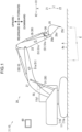
- FIG. 1 is a side view of a working machine 10 and other elements concerning the excavation route generation system 1 according to the embodiment of the present invention.
- Fig. 2 is a block diagram of the excavation route generation system 1 illustrated in Fig. 1 .
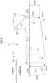
- Fig. 3 is an illustration of an example of an excavation route E illustrated in Fig. 1 .
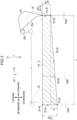
- Fig. 4 is an illustration of an excavation route E having a greater excavation depth D than the example of the excavation route E illustrated in Fig. 3 .
- Fig. 5 is an explanatory view for the excavation route E illustrated in Fig. 3 .
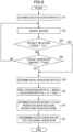
- Fig. 6 is a flowchart showing an operation of the controller 70 shown in Fig. 2 .
- the excavation route generation system 1 generates a route, i.e., an excavation route E, of a bucket 25 in an excavation (excavation work) of the working machine 10.
- the excavation route generation system 1 includes the working machine 10, a posture sensor 51, a property sensor 53 (see Fig. 2 ), an image capturing device 55, a manipulation device 60 (see Fig. 2 ), and the controller 70 (see Fig. 2 ).
- the excavation route generation system 1 may include a part of the working machine 10, or may not include the working machine 10 and may be arranged outside the working machine 10.
- the working machine 10 performs an excavation, and is, for example, an excavator.
- the working machine 10 is configured to execute autonomous driving.
- the working machine 10 includes a machine main body 11, an attachment 20, an actuator 30, and a drive control part 40 (see Fig. 2 ).
- the machine main body 11 is a main body of the working machine 10.
- the machine main body 11 includes a lower traveling body 11a and an upper slewing body 11b.
- the lower traveling body 11a is configured to travel on a traveling surface, such as the ground.
- the lower traveling body 11a may have a crawler, or may have a wheel.
- the upper slewing body 11b is slewably mounted on the lower traveling body 11a.
- the attachment 20 is attached to the upper slewing body 11b.
- the upper slewing body 11b has an operating compartment 11b1.
- Upward and downward directions of the machine main body 11 are defined as “machine upward and downward directions”.
- the machine upward and downward directions indicate directions in which a rotation axis of the upper slewing body 11b to slew with respect to the lower traveling body 11a extends.
- Directions in which a rotation axis of the attachment 20 (more specifically, a boom 21 to be described later) to be raised and be lowered with respect to the upper slewing body 11b extends are defined as "lateral directions”.
- Directions perpendicular intersecting each of the machine upward and downward directions and the lateral directions are defined as forward and rearward directions X.
- a direction in which the attachment 20 protrudes from the upper slewing body 11b is defined as a farther direction X1 and a direction opposite thereto is defined as a closer direction X2.
- the farther direction X1 agrees with a forward direction
- the closer direction X2 agrees with a rearward direction.
- the attachment 20 is attached to the machine main body 11 (more specifically, attached to the upper slewing body 11b).
- the attachment 20 executes a work.
- the attachment 20 has the boom 21, an arm 23, the bucket 25, and a bucket rotation link 26.
- the boom 21 is attached to the upper slewing body 11b in a tiltable manner, that is, rotatably in the machine upward and downward directions.
- the arm 23 is attached to the boom 21 rotatably, that is, rotatably in the forward and rearward directions X and in the machine upward and downward directions.
- the bucket 25 is provided on a distal end of the attachment 20.
- the bucket 25 is attached to the arm 23 rotatably, that is, rotatably in the forward and rearward directions and in the machine upward and downward directions.
- the bucket 25 has a bucket proximal end 25b, a bucket opening plane 25o, and a bucket distal end 25t.
- the bucket proximal end 25b is an end of the bucket 25 (that is attached to the arm 23) that is closer to the arm 23.
- the bucket proximal end 25b serves to constitute a rotation axis of the bucket 25 with respect to the arm 23.
- the bucket opening plane 25o is an opening plane of the bucket 25.
- the bucket distal end 25t is another end (e.g., a claw end) of the bucket 25 that is opposite to the bucket proximal end 25b.
- the bucket 25 excavates an excavation object A.
- the excavation object A is in a soil, granular, chip, or powdery shape.
- the excavation object A may be in the form of soil and sand, stone, metal, resin, rubber, or industrial waste.
- the excavation object A has a surface As, i.e., an upper surface, which may include a flat section or a substantially flat section, and may include a curvy section.
- the surface As may include a horizontal section or a substantially horizontal section, and may include a flat section or a substantially flat section tilting relative to a horizontal direction.
- the surface As may have a shape in combination of a plurality of flat sections or substantially flat sections (e.g., in combination of horizontal sections and sloping sections).
- the posture sensor 51 i.e., a posture detector, detects a posture of the working machine 10.
- the posture sensor 51 has a boom sensor 51a, an arm sensor 51c, and a bucket sensor 51e.
- the boom sensor 51a detects a posture of the boom 21.
- the arm sensor 51c detects a posture of the arm 23.
- the bucket sensor 51e detects a posture of the bucket 25.
- the boom sensor 51a may detect an angle (a tilt or a rotation angle) of the boom 21 to the horizontal direction or the upper slewing body 11b.
- Each of the arm sensor 51c and the bucket sensor 51e may detect an angle or other parameter to the horizontal direction or to a constituent element of the working machine 10 in the same manner.
- the boom sensor 51a may include a tilt sensor, such as a gyro sensor, an acceleration sensor, or an inertial measurement unit, which detects an angle of the boom 21 to the horizontal direction.
- a tilt sensor such as a gyro sensor, an acceleration sensor, or an inertial measurement unit, which detects an angle of the boom 21 to the horizontal direction.
- Each of the arm sensor 51c and the bucket sensor 51e may include such a tilt sensor in the same manner.
- the boom sensor 51a may include an angle sensor (e.g., a rotary encoder) attached to a rotation shaft or a rotation support of the boom 21 with respect to the upper slewing body 11b.
- Each of the arm sensor 51c and the bucket sensor 51e may include such an angle sensor in the same manner.
- the boom sensor 51a may include a stroke sensor that detects a stroke of the cylinder, i.e., the boom cylinder 31, which drives the boom 21.
- Each of the arm sensor 51c and the bucket sensor 51e may include such a stroke sensor in the same manner.
- the boom sensor 51a may detect a posture of the boom 21 on the basis of at least one of a two-dimensional image and a distance image.
- the arm sensor 51c and the bucket sensor 51e may adopt such a detection way in the same manner.
- the image capturing device 55 (to be described later) may capture at least one of a two-dimensional image and a distance image.
- the posture sensor 51 may be mounted on the working machine 10, or may be arranged outside the working machine 10, for example, may be arranged at a worksite.
- Each of the property sensor 53 (see Fig. 2 ), the image capturing device 55, the manipulation device 60, and the controller 70 (see Fig. 2 ) may also be arranged on the working machine 10 or arranged outside the working machine 10.
- the property sensor 53 detects a property (e.g., a soil and sand quality) of the excavation object A.
- a property e.g., a soil and sand quality
- the property sensor 53 includes a hardness sensor 53a and a shape sensor 53c.
- the hardness sensor 53a detects hardness of the excavation object A illustrated in Fig. 1 .
- the hardness sensor 53a may detect (calculate, estimate) hardness of the excavation object A on the basis of a reaction force received by the bucket 25, "bucket 25-reaction force", from the excavation object A.
- the hardness sensor 53a may be provided to the attachment 20, or may be provided to the actuator 30.
- the hardness sensor 53a may be provided to the bucket 25, or may be provided to other member that receives the reaction force of the bucket 25.
- the hardness sensor 53a may detect distortion of the bucket rotation link 26, or may detect distortion of the bucket cylinder 35.
- the hardness sensor 53a may detect a hydraulic pressure of the bucket cylinder 35.
- the hardness sensor 53a may be provided to, for example, at least one of the boom 21, the arm 23, the boom cylinder 31, the arm cylinder 33, the upper slewing body 11b, and the lower traveling body 11a.
- the hardness sensor 53a may detect hardness of the excavation object A on the basis of information except the reaction force of the bucket 25.
- the hardness sensor 53a may detect hardness of the excavation object A through contact of another member except the bucket 25 with the excavation object A.
- the hardness sensor 53a may include a member (e.g., a rod-shaped member) to be inserted in the excavation object A.
- the hardness sensor 53a may detect hardness of the excavation object A without contact with the excavation object A.
- the hardness sensor 53a may detect the hardness of the excavation object A on the basis of an image of the excavation object A (e.g., the excavation object A in at least one of a state of being excavated and a state of having been excavated).
- the controller 70 stores learning data based on pre-learning of a relation between an image of the excavation object A and hardness thereof.
- the hardness sensor 53a e.g., the image capturing device 55
- the hardness of the excavation object A may be detected or estimated on the basis of the captured image of the excavation object A and the learning data.
- the hardness sensor 53a may include the image capturing device 55 and the controller 70.
- the shape sensor 53c detects a shape of the surface As of the excavation object A.
- the shape sensor 53c may be, for example, the image capturing device 55.
- the image capturing device 55 captures an image of an image capturing object.
- the image capturing object of the image capturing device 55 may be a whole of the working machine 10, or may be the attachment 20.
- the image capturing device 55 serves as the property sensor 53
- the image capturing object of the image capturing device 55 is the excavation object A.
- the image capturing device 55 may detect two-dimensional information (e.g., a position and a shape in the image) about the image capturing object.
- the image capturing device 55 may include a camera (monocular camera) that detects the two-dimensional information.
- the image capturing device 55 may acquire a distance image, or detect three-dimensional information (e.g., a three-dimensional coordinate or a three-dimensional shape) about the image capturing object on the basis of the distance image.
- the image capturing device 55 may include a stereo camera.
- the image capturing device 55 may detect a distance to the image capturing object by irradiating the image capturing object with waves, such as electromagnetic waves, and detecting reflected waves.
- the image capturing device 55 may include, for example, a Time Of Flight (TOF) sensor that detects the distance on the basis of a time from the irradiation with the waves to return of the reflected waves, or may include a sensor that detects the distance on the basis of a frequency of the reflected waves.
- TOF Time Of Flight
- the image capturing device 55 may include a detector that detects three-dimensional information with light (e.g., with a laser beam), or may include a Light Detection and Ranging (LIDAR) sensor.
- the image capturing device 55 may include a detector (e.g., a millimeter-wave radar) that detects three-dimensional information with radio waves.
- the image capturing device 55 may detect three-dimensional information about the image capturing object on the basis of a distance image and a two-dimensional image. Only a single image capturing device 55 may be provided, or a plurality of image capturing devices 55 may be provided.
- the manipulation device 60 receives an input of information from an operator.
- the manipulation device 60 inputs an instruction signal for an instruction into the controller 70 (see Fig. 2 ) in response to a manipulation by the operator.
- the manipulation device 60 may include a tablet, a mobile terminal, such as a smartphone, or a personal computer.
- the manipulation device 60 may be provided to a server.
- a communicator to establish communication between the working machine 10 and the manipulation device 60 is provided.
- the communication through the communicator may be wireless communication or wired communication.
- the manipulation device 60 may be arranged, for example, in the operating compartment of the upper slewing body 11b.
- the controller 70 includes a computer that executes: inputting and outputting of a signal; computation (processing); and storage of information.
- the operability of the controller 70 shown in Fig. 2 comes into effect when a computation part executes a program stored in a storage part of the controller 70.
- the controller 70 receives an input of a signal (specifically, a detection result, or a manipulation result) from each of the posture sensor 51, the property sensor 53, and the manipulation device 60, that is, receives the signal.
- the controller 70 enables the working machine 10 (see Fig. 1 ) to execute autonomous driving.
- the controller 70 inputs an instruction for activating the working machine 10 into the drive control part 40.
- the controller 70 has a posture acquisition part 71, a property acquisition part 73, an excavation route generation part 75, and an autonomous driving control part 77.
- the posture acquisition part 71 acquires posture information about the attachment 20 (see Fig. 1 ) detected by the posture sensor 51.
- the property acquisition part 73 acquires information about a property (e.g., a soil and sand quality) of the excavation object A (see Fig. 1 ).
- the property acquisition part 73 has a hardness acquisition section 73a and a shape acquisition section 73c.
- the hardness acquisition section 73a acquires the hardness (property) of the excavation object A.
- the hardness acquisition section 73a acquires information about the hardness of the excavation object A detected by the hardness sensor 53a.
- the shape acquisition section 73c acquires the shape (property) of the excavation object A.
- the shape acquisition section 73c acquires information about the shape of the excavation object A detected by the shape sensor 53c.
- the excavation route generation part 75 generates an excavation route E illustrated in Fig. 1 .
- the excavation route E includes a route to be a target of the bucket 25 in excavating the excavation object A in an excavation by the bucket 25.
- the excavation route E includes a target route about a work position in an excavation work by the bucket 25.
- the excavation route E includes a target route of a specific portion of the bucket 25.
- the excavation route E is a target route of the bucket distal end 25t.
- the case of the excavation route E being the target route of the bucket distal end 25t will be described.
- Generation of the excavation route E (see Fig. 1 ) by the excavation route generation part 75 in Fig. 2 will be described in detail later.
- the autonomous driving control part 77 causes the working machine 10 (see Fig. 1 ) to execute autonomous driving.
- the autonomous driving control part 77 inputs an instruction into the drive control part 40 shown in Fig. 2 to cause the working machine 10 (the bucket 25) to perform an excavation along the excavation route E illustrated in Fig. 1 .
- the autonomous driving control part 77 controls an operation of the working machine 10 on the basis of the posture of the attachment 20 detected by the posture sensor 51.
- the excavation route generation system 1 shown in Fig. 1 is configured to operate as described below.
- the controller 70 and the constituent elements (including the excavation route generation part 75 and other parts) of the controller 70 will be described with reference to Fig. 2 .
- the working machine 10 (the bucket 25) illustrated in Fig. 1 performs an excavation along an excavation route E generated by the excavation route generation part 75.
- the excavation represents an excavation of the excavation object A by the bucket 25 as illustrated in Fig. 3 .
- the excavation includes an insertion operation, a pulling operation, and a scooping operation. The excavation is executed in the order of the insertion operation, the pulling operation, and the scooping operation.
- the excavation route E generated by the excavation route generation part 75 includes information about a position to be a target of the bucket 25 and information about a direction of movement of the bucket 25.
- the excavation route E includes an initial excavation path Ea, an intermediate excavation path Eb, and a final excavation path Ec.
- the target is set so that the bucket distal end 25t (a specific portion of the bucket 25) passes the initial excavation path Ea, the intermediate excavation path Eb, and the final excavation path Ec in this order.
- the excavation route E includes a target point P.
- the target point P indicates a point that the bucket distal end 25t passes as a target.
- information about the target point P includes a three-dimensional position coordinate.
- the excavation route E includes a plurality of the target points P.
- the target is set so that the bucket distal end 25t passes the target points P in a predetermined order.
- the target points P include a first target point P1, a second target point P2, a third target point P3, and a fourth target point P4.
- the target is set so that the bucket distal end 25t passes the first target point P1, the second target point P2, the third target point P3, and the fourth target point P4 in this order.
- the insertion operation is an operation of inserting the bucket 25 into the excavation object A.
- the insertion operation is an operation of making the bucket 25 move from the outside to the inside of the excavation object A in the excavation downward direction Z2.
- the bucket proximal end 25b moves in the excavation downward direction Z2.
- an angle of the bucket 25, "bucket 25-rotation angle", to the arm 23 may be constant or substantially constant, or may change.
- the bucket distal end 25t may rotate in the closer direction X2 with respect to the bucket proximal end 25b.
- the excavation route generation part 75 sets the initial excavation path Ea included in the excavation route E for the insertion operation.
- the initial excavation path Ea includes the first target point P1 and the second target point P2.
- the first target point P1 serves as a start point of the initial excavation path Ea.
- the first target point P1 is set at a position on the surface As of the excavation object A.
- the second target point P2 serves as a finish point of the initial excavation path Ea and a start point of the intermediate excavation path Eb.
- the second target point P2 is set at a farther downward position (inside the excavation object A) than the surface As in the excavation downward direction Z2.
- the third target point P3 is set in the same manner.
- the second target point P2 may be at the same position in the forward and rearward directions X as the position of the first target point P1 in the forward and rearward directions X, or may be at a closer position than the first target point P1 in the closer direction X2, or may be at a farther position than the first target point P1 in the farther direction X1.
- Directions in which the initial excavation path Ea faces include the excavation downward direction Z2.
- the initial excavation path Ea may face in the excavation downward direction Z2 and in the farther direction X1 (obliquely downward), or may face in the excavation downward direction Z2 and in the closer direction X2 (obliquely downward).
- the initial excavation path Ea faces farther downward than a first vector V1 illustrated in Fig. 5 in the excavation downward direction Z2 (downward) so as to be closer to the vertical direction.
- the first vector V1 is a vector being at a tilt angle of 45° relative to the excavation upward and downward directions Z and progressing in the closer direction X2 and the excavation downward direction Z2.
- the pulling operation is an operation of making the bucket 25 move in the closer direction X2 in a state where the bucket 25 illustrated in Fig. 3 is inside (is inserted in) the excavation object A.
- the bucket proximal end 25b and the bucket distal end 25t move in the closer direction X2.
- the bucket 25 may move in parallel to or substantially parallel to the surface As of the excavation object A and in the closer direction X2.
- the pulling operation may include causing the bucket 25 to move horizontally or substantially horizontally, i.e., execute horizontal pulling, in the closer direction X2.
- the machine main body 11 see Fig.
- a rotation angle of the bucket 25 to the arm 23 may be constant or substantially constant, or may change.
- the excavation route generation part 75 sets the intermediate excavation path Eb included in the excavation route E for the pulling operation.
- the intermediate excavation path Eb includes the second target point P2 and the third target point P3.
- the third target point P3 serves as a finish point of the intermediate excavation path Eb and serves as a start point of the final excavation path Ec.
- Directions in which the intermediate excavation path Eb faces include the closer direction X2.
- the intermediate excavation path Eb may face in the closer direction X2 and the excavation upward direction Z1 (obliquely upward), or may face in the closer direction X2 and in the excavation downward direction Z2 (obliquely downward).
- the intermediate excavation path Eb faces in the closer direction X2 to be nearly parallel to the forward and rearward directions X in comparison with the first vector V1 and a second vector V2 illustrated in Fig. 5 .
- the second vector V2 is a vector being at a tilt angle of 45° relative to the excavation upward and downward directions Z and progressing in the closer direction X2 and the excavation upward direction Z1.
- the scooping operation is an operation of scooping the bucket 25 upward from the inside of the excavation object A illustrated in Fig. 3 through the surface As.
- the scooping operation is an operation of making the bucket 25 move in the excavation upward direction Z1 from a farther downward position than the surface As in the excavation downward direction Z2.
- the bucket 25 moves in the excavation upward direction Z1 in the state where the bucket 25 accommodates the excavation object A therein, that is, in the state where the bucket 25 has scooped the excavation object A.
- the bucket opening plane 25o faces vertically upward or substantially vertically upward.
- the bucket proximal end 25b may move in the farther direction X1 while the bucket distal end 25t rotates in the closer direction X2 and vertically upward with respect to the bucket proximal end 25b (rotates in a scooping direction).
- the bucket distal end 25t may rotate in the closer direction X2 and vertically upward (rotates in a scooping direction) with respect to the bucket proximal end 25b while the bucket proximal end 25b is at a fixed position or a substantially fixed position in the forward and rearward directions X.
- the excavation route generation part 75 sets the final excavation path Ec included in the excavation route E for the scooping operation.
- the final excavation path Ec includes the third target point P3 and the fourth target point P4.
- the fourth target point P4 serves as a finish point of the final excavation path Ec.
- the fourth target point P4 is set at a position on the surface As.
- the fourth target point P4 may be at the same position in the forward and rearward directions X as the position of the third target point P3 in the forward and rearward directions X, or may be located downstream of the third target point P3 in the closer direction X2, or may be located downstream of the third target point P3 in the farther direction X1.
- Directions in which the final excavation path Ec faces include the excavation upward direction Z1.
- the final excavation path Ec may face in the excavation upward direction Z1 and the farther direction X1 (obliquely upward), or may face in the excavation upward direction Z1 and the closer direction X2 (obliquely upward).
- the final excavation path Ec faces farther upward than the second vector V2 (see Fig. 5 ) in the excavation upward direction Z1 so as to be closer to the vertical direction.
- the excavation may exclude at least one of the insertion operation and the scooping operation.
- the excavation may be finished in such a manner that the pulling operation is executed after the insertion operation without execution of the scooping operation.
- the pulling operation and the scooping operation may be executed without execution of the insertion operation.
- the excavation may be finished in such a manner that the pulling operation is executed without execution of the insertion operation and the scooping operation.
- the target points P may be settable at various positions. For instance, one or more target points P may be set between the first target point P1 and the second target point P2, and may be set between the second target point P2 and the third target point P3 and between the third target point P3 and the fourth target point P4 in the same manner.
- the bucket distal end 25t (a specific portion of the bucket 25) may linearly move or curvilinearly move between adjacent target points P in order.
- the excavation route generation part 75 generates an excavation route E in accordance with a property (e.g., a soil and sand quality) of the excavation object A.
- the excavation route generation part 75 generates the excavation route E in accordance with hardness of the excavation object A.
- the excavation route generation part 75 may generate the excavation route E in accordance with the hardness and a shape of the excavation object A.
- the excavation route generation part 75 sets an excavation depth D and an excavation distance L as parameters of the excavation route E.
- the excavation depth D is a depth of the bucket 25 with respect to the surface As of the excavation object A.
- the excavation depth D indicates a distance from the surface As to the bucket distal end 25t (the specific portion of the bucket 25) in the excavation upward and downward directions Z.
- the "surface As” means the surface As of the excavation object A having been subjected to the excavation.
- the excavation upward and downward directions Z perpendicularly intersect the surface As.
- the excavation upward and downward directions Z may differ depending on a position (a point or a range, hereinafter referred to as a "reference position") on the surface As to be a reference in the excavation upward and downward directions Z.
- the excavation route generation part 75 presets a specific position on the surface As as the reference position.
- the excavation route generation part 75 presets a reference position for each of the operations of the insertion operation, the pulling operation, and the scooping operation.
- the reference position for the insertion operation is set at the first target point P1 serving as a start position for the insertion operation or set in a predetermined range around the first target point P1.
- the reference position for the scooping operation is set to the fourth target point P4 serving as a finish position for the scooping operation or set in a predetermined range around the target point P.
- the reference position for the pulling operation may be the same as the reference position for the insertion operation, may be the same as the reference position for the scooping operation, or may be a position (e.g., a middle position therebetween) except these positions.
- the excavation route generation part 75 changes or sets the excavation depth D in accordance with the hardness of the excavation object A acquired by the hardness acquisition section 73a (the property acquisition part 73).
- the excavation route generation part 75 sets the excavation depth D to a first excavation depth when the hardness of the excavation object A acquired by the hardness acquisition section 73a indicates first hardness (see Fig. 4 ).
- the excavation route generation part 75 sets the excavation depth D to a second excavation depth which is smaller than the first excavation depth when the hardness of the excavation object A acquired by the hardness acquisition section 73a indicates second hardness which is higher than the first hardness (see Fig. 3 ).
- the excavation route generation part 75 makes the excavation depth D shallower (smaller) as the hardness of the excavation object A is harder (higher).
- the excavation route generation part 75 makes the excavation depth D deeper (greater) as the hardness of the excavation object A is softer (lower).
- the excavation route generation part 75 may gradually reduce the excavation depth D or continuously reduce the excavation depth D as the hardness of the excavation object A is higher.
- a too great excavation depth D may lead to, for example, disadvantages to be described below.
- a too great excavation depth D leads to a too large quantity of the excavation object A scooped upward by the bucket 25.
- a rear portion of the machine main body 11 (specifically, the lower traveling body 11a) in Fig. 1 that is located opposite the attachment 20 may rise from a ground surface, resulting in a disadvantage of the rise of the rear portion of the vehicle body.
- the bucket 25 may fail to satisfactorily accommodate the excavation object A and the excavation object A may overflow the bucket 25, which results in a disadvantage of a failure at accommodating the excavation object A. This may make the excavation at the great excavation depth D end up in an unnecessary operation.
- a too great excavation depth D in the insertion operation may lead to a too large reaction force received by the bucket 25 from the excavation object A.
- a front portion (the attachment 20) of the machine main body 11 may rise from the ground surface, resulting in a disadvantage of the rise of the front portion of the vehicle body.
- a too small excavation depth D leads to, for example, disadvantages to be described below.
- a too small excavation depth D may lead to a failure at ensuring a satisfactory excavation quantity of the excavation object A through a one-time excavation, resulting in a disadvantage of an unsatisfactory excavation quantity.
- the excavation route generation part 75 preferably sets the excavation depth D to an appropriate degree without making the excavation depth D too great or too small so as to avoid the disadvantages.
- the excavation route generation part 75 may set the initial excavation depth Da or the final excavation depth Dc as the excavation depth D.
- the excavation route generation part 75 may set the intermediate excavation depth Db as the excavation depth D.
- a limit value (an excavation depth limit value) of the excavation depth D may be set in the excavation route generation part 75.
- an initial excavation depth limit value ThDA, an intermediate excavation depth limit value ThDb, and a final excavation depth limit value ThDc may be set in the excavation route generation part 75.
- the initial excavation depth Da is an excavation depth D at a finish of the insertion operation at the second target point P2.
- the initial excavation depth Da indicates an insertion amount (initial bucket insertion amount) of the bucket 25 into the excavation object A in insertion of the bucket 25 in the excavation object A, that is, an insertion amount in the insertion operation.
- the initial excavation depth Da indicates a distance from the surface As of the excavation object A to the bucket distal end 25t (the specific portion of the bucket 25) at a finish of the insertion operation in the excavation upward and downward directions Z.
- a reference position in the excavation upward and downward directions Z is, for example, the "reference position for the insertion operation" .
- the excavation route generation part 75 changes the initial excavation depth Da (see Fig. 3 and Fig. 4 ) in accordance with the hardness of the excavation object A acquired by the hardness acquisition section 73a (the property acquisition part 73).
- the excavation route generation part 75 sets, as the initial excavation depth Da, an insertion amount of the bucket 25 when the reaction force received by the bucket 25 from the excavation object A exceeds the reaction force threshold Th1.
- the "insertion amount” is defined in the same manner as the definition of the "excavation depth D".
- the excavation route generation part 75 sets the initial excavation depth Da during execution of the insertion operation by the bucket 25.
- the excavation route generation part 75 increases the initial excavation depth Da until the reaction force received by the bucket 25 exceeds the reaction force threshold Th1.
- the reaction force threshold Th1 is preset in the excavation route generation part 75 before the setting of the initial excavation depth Da.
- the reaction force threshold Th1 is set to, for example, such a value as to avoid the disadvantage of the rise of the front portion of the vehicle body like "Disadvantage Example B3".
- the reaction force threshold Th1 is set on the basis of stability of the machine main body 11 (see Fig. 1 ), such as a mass balance in the forward and rearward directions X.
- the initial excavation depth Da may not be set on the basis of the reaction force threshold Th1.
- a relation (such as a relational expression or a map) between the hardness of the excavation object A and the excavation depth D, here, the initial excavation depth Da, to be set may be preset in the excavation route generation part 75.
- the excavation route generation part 75 may set the initial excavation depth Da on the basis of the hardness of the excavation object A acquired by the hardness acquisition section 73a and the relation.
- the excavation route generation part 75 may set the intermediate excavation depth Db and the final excavation depth Dc on the basis of a relation (such as a relational expression or a map) between the excavation object A and the excavation depth D.
- the initial excavation depth limit value ThDa (an excavation depth limit value) is a limit value of the initial excavation depth Da.
- the excavation route generation part 75 limits the initial excavation depth Da on the basis of the initial excavation depth limit value ThDa.
- the excavation route generation part 75 limits the initial excavation depth Da in such manner as to keep the initial excavation depth Da from exceeding the initial excavation depth limit value ThDa.
- the excavation route generation part 75 limits the initial excavation depth Da to be equal to, to be substantially equal to, or to be smaller than the initial excavation depth limit value ThDa.
- the initial excavation depth limit value ThDa is preset in the excavation route generation part 75 before the setting of the initial excavation depth Da.
- the initial excavation depth limit value ThDa is set to such a value as to avoid the disadvantages that the excavation depth D is too great like Disadvantage Example B1 and Disadvantage Example B2.
- An intermediate excavation depth limit value ThDb and a final excavation depth limit value ThDc to be described later are set in the same manner.
- the initial excavation depth limit value ThDa is set to a value described below.
- a rotation angle of the bucket 25 is defined as a predetermined angle at a finish of the insertion operation. In the example in Fig. 3 , the "predetermined angle at a finish of the insertion operation" indicates a rotation angle of the bucket 25 at which the bucket opening plane 25o tilts about 45° relative to the excavation upward and downward directions Z.
- the bucket 25 is arranged so that a most part of the bucket 25 is inserted in the excavation object A and only a part of the bucket 25 is outside the excavation object A in a state where the rotation angle of the bucket 25 reaches the predetermined angle at the finish of the insertion operation.
- the excavation depth D of the bucket distal end 25t is set as the initial excavation depth limit value ThDa.
- the initial excavation depth limit value ThDa is just an example, and the initial excavation depth limit value ThDa may be settable to any value from various aspects.
- the final excavation depth Dc is an excavation depth D at a start of the scooping operation at the third target point P3.
- the final excavation depth Dc indicates a distance from the surface As of the excavation object A to the bucket distal end 25t (the specific portion of the bucket 25) at the start of the scooping operation in the excavation upward and downward directions Z.
- a reference position in the excavation upward and downward directions Z is, for example, the "reference position for the scooping operation”.
- the excavation route generation part 75 changes or sets the final excavation depth Dc in accordance with the hardness of the excavation object A acquired by the hardness acquisition section 73a (the property acquisition part 73).
- the excavation route generation part 75 may set the final excavation depth Dc on the basis of a depth difference ⁇ .
- the depth difference ⁇ is a difference (an offset amount) between the initial excavation depth Da and the final excavation depth Dc.
- the depth difference ⁇ is a difference between the initial excavation depth Da and the final excavation depth Dc in the excavation upward and downward directions Z.
- the depth difference ⁇ may be more than 0, that is, the final excavation depth Dc may be greater than the initial excavation depth Da.
- the depth difference ⁇ may be less than 0, that is, the final excavation depth Dc may be smaller than the initial excavation depth Da.
- the depth difference ⁇ may be set to 0, that is, the final excavation depth Dc may be equal to the initial excavation depth Da.
- the depth difference ⁇ may be a fixed value preset in the excavation route generation part 75 before the setting of the excavation depth D.
- the depth difference ⁇ may be set in the excavation route generation part 75 in accordance with a property of the excavation object A acquired by the property acquisition part 73. Specifically, the excavation route generation part 75 may change the depth difference ⁇ in accordance with hardness of the excavation object A acquired by the hardness acquisition section 73a. The excavation route generation part 75 sets the depth difference ⁇ to avoid the disadvantages of the too great excavation depth D and the disadvantages of the too small excavation depth D described above. Specifically, for instance, the excavation route generation part 75 may reduce the depth difference ⁇ and make the final excavation depth Dc smaller than the initial excavation depth Da as the hardness of the excavation object A is higher. The excavation route generation part 75 may increase the depth difference ⁇ and make the final excavation depth Dc greater than the initial excavation depth Da as the hardness of the excavation object A is lower.
- the excavation route generation part 75 may set the final excavation depth Dc without relying on the initial excavation depth Da.
- the excavation route generation part 75 may set the final excavation depth Dc on the basis of the property (e.g., hardness) of the excavation object A at a position for the pulling operation or the scooping operation without relying on the initial excavation depth Da.
- the final excavation depth limit value ThDc (an excavation depth limit value) is a limit value of the final excavation depth Dc.
- the excavation route generation part 75 limits the final excavation depth Dc in such manner as to keep the final excavation depth Dc from exceeding the final excavation depth limit value ThDc.
- the excavation route generation part 75 limits the final excavation depth Dc to be equal to, to be substantially equal to, or to be smaller than the final excavation depth limit value ThDc.
- the final excavation depth limit value ThDc is preset in the excavation route generation part 75 before the setting of the final excavation depth Dc.
- the final excavation depth limit value ThDc is set in the same manner as the initial excavation depth limit value ThDa.
- the final excavation depth limit value ThDc may be equal to or different from the initial excavation depth limit value ThDa.
- the intermediate excavation depth limit value ThDb and the initial excavation depth limit value ThDa may have a similar relation.
- the intermediate excavation depth Db is an excavation depth D in the pulling operation.
- the intermediate excavation depth Db is an excavation depth D from the finish of the insertion operation at the second target point P2 to the start of the scooping operation at the third target point P3.
- the intermediate excavation depth Db indicates a distance from the surface As of the excavation object A to the bucket distal end 25t (the specific portion of the bucket 25) in the pulling operation in the excavation upward and downward directions Z.
- a reference position in the excavation upward and downward directions Z is, for example, the "reference position for the pulling operation".
- the excavation route generation part 75 may set or may not set the intermediate excavation depth Db.
- the intermediate excavation depth Db may be set on the basis of the initial excavation depth Da in the same manner that the final excavation depth Dc may be set on the basis of the initial excavation depth Da as described above, or the intermediate excavation depth Db may be set on the basis of the final excavation depth Dc. At least one of the initial excavation depth Da and the final excavation depth Dc may be set on the basis of the intermediate excavation depth Db.
- the intermediate excavation depth limit value ThDb (an excavation depth limit value) is a limit value of the intermediate excavation depth Db.
- the excavation route generation part 75 limits the intermediate excavation depth Db in such a manner as to keep the intermediate excavation depth Db from exceeding the intermediate excavation depth limit value ThDb.
- the intermediate excavation depth limit value ThDb is preset in the excavation route generation part 75 before the setting of the intermediate excavation depth Db. For instance, the intermediate excavation depth limit value ThDb is set in the same manner as the initial excavation depth limit value ThDa.
- the excavation distance L is a moving distance of the bucket 25 in the forward and rearward directions X from a state of the bucket 25 having been inserted in the excavation object A to a state of the bucket 25 to be scooped upward from the inside of the excavation object A through the surface As.
- the excavation distance L is a moving distance of the bucket 25 in the forward and rearward directions X in the pulling operation. More specifically, the excavation distance L is a moving distance of the bucket 25 (e.g., the bucket distal end 25t) in the forward and rearward directions X from the finish of the insertion operation (e.g., from the second target point P2) to the start of the scooping operation (e.g., to the third target point P3).
- a too long excavation distance L may lead to the disadvantage of the rise of the rear portion of the vehicle body like “Disadvantage Example B1” and the disadvantage of the failure at satisfactorily accommodating the excavation object A in the bucket 25 like “Disadvantage Example B2".
- a too short excavation distance L may lead to the disadvantage of the failure at ensuring a satisfactory excavation quantity of the excavation object A through a one-time excavation like "Disadvantage Example C1".
- the excavation route generation part 75 preferably sets the excavation distance L to an appropriate value without making the excavation distance L too long and too short so as to avoid the disadvantages.
- the excavation route generation part 75 changes or sets the excavation depth D in accordance with the hardness of the excavation object A acquired by the hardness acquisition section 73a.
- the excavation route generation part 75 then changes the excavation distance L on the basis of the excavation depth D.
- the excavation route generation part 75 changes the excavation distance L in accordance with the hardness of the excavation object A acquired by the hardness acquisition section 73a.
- the excavation route generation part 75 sets the excavation distance L to a first excavation distance when setting the excavation depth D to the first excavation depth (see Fig. 4 ).
- the excavation route generation part 75 sets the excavation distance L to a second excavation distance which is longer than the first excavation distance when setting the excavation depth D to the second excavation depth which is smaller than the first excavation depth (see Fig. 3 ).
- the excavation route generation part 75 may reduce the excavation depth D and increase the excavation distance L as the hardness of the excavation object A is higher.
- the excavation route generation part 75 may increase the excavation depth D and reduce the excavation distance L as the hardness of the excavation object A is lower.
- the excavation route generation part 75 may gradually reduce the excavation distance L or may continuously reduce the excavation distance L as the excavation depth D is greater.
- the excavation route generation part 75 may set the excavation distance L so that a prospective excavation volume reaches a target excavation volume.
- the "prospective excavation volume” indicates a prospective volume of the excavation object A to be excavated when the bucket 25 executes an excavation along a certain excavation route E.
- the prospective excavation volume is a volume of a region where the excavation object A exists and which the bucket 25 is supposed to pass through when the bucket 25 moves along the excavation route E.
- a specific example of the prospective excavation volume will be described in detail below.
- an area of a region surrounded by the surface As of the excavation object A and the excavation route E (the hatched region in Fig. 3 ) is defined as an "excavation area”.
- the prospective excavation volume is a product of the "excavation area" and a width of the bucket 25 in the lateral direction, or a value resulting from correcting the product or other value.
- the excavation route generation part 75 determines a first target point P1 (a start point of the excavation route E, that is, an excavation start position) shown in Fig. 3 .
- the excavation route generation part 75 may determine the first target point P1 on the basis of a shape of the excavation object A acquired by the shape acquisition section 73c, information about a plan of an excavation work set in the controller 70, information about a progress of the excavation work, and other information.
- step S23 the excavation route generation part 75 determines whether the insertion amount of the bucket 25 is equal to or larger than an initial excavation depth limit value ThDa.
- the excavation route generation part 75 proceeds to the next step.
- the excavation route generation part 75 determines the insertion amount of the bucket 25 (at processing in step S23) as the initial excavation depth Da (step S24).
- the process returns to step S21.
- the autonomous driving control part 77 causes the bucket 25 to be further inserted in the excavation object A.
- the excavation route generation part 75 calculates a final excavation depth Dc on the basis of the initial excavation depth Da, that is, the initial excavation depth Da determined in step S24. Specifically, the excavation route generation part 75 calculates a sum of the initial excavation depth Da and a depth difference ⁇ . When the calculated sum is equal to or smaller than a final excavation depth limit value ThDc, the excavation route generation part 75 defines the sum of the initial excavation depth Da and the depth difference ⁇ as the final excavation depth Dc. When the calculated sum is larger than the final excavation depth limit value ThDc, the excavation route generation part 75 defines the final excavation depth limit value ThDc as the final excavation depth Dc.
- the excavation route generation part 75 determines an excavation distance L.
- the excavation route generation part 75 determines the excavation distance L so that a prospective excavation volume (as described above) reaches a target excavation volume (e.g., a multiple ⁇ of the capacity of the bucket 25 as described above).
- the excavation route generation part 75 sets an excavation route E (a final excavation path Ec) for a scooping operation. For instance, a shape of the excavation route E from the third target point P3 to the fourth target point P4 is preset in the excavation route generation part 75.
- the excavation route generation part 75 may correct the excavation route E set by the excavation route generation part 75 in response to a manipulation to the manipulation device 60 illustrated in Fig. 1 .
- the excavation route generation part 75 may correct each parameter of the excavation route E in response to a manipulation to the manipulation device 60.
- the excavation route generation part 75 may correct at least one of the excavation depths D including the initial excavation depth Da, the intermediate excavation depth Db and the final excavation depth Dc, and the excavation distance L illustrated in Fig. 3 in response to a manipulation to the manipulation device 60.
- the excavation route generation part 75 may correct at least one of the reaction force threshold Th1, the initial excavation depth limit value ThDa, the intermediate excavation depth limit value ThDb, and the final excavation depth limit value ThDc in response to a manipulation to the manipulation device 60.
- the excavation route generation part 75 may correct at least one of the depth difference ⁇ and the target excavation volume (e.g., the multiple ⁇ ) in response to a manipulation to the manipulation device 60.
- the excavation route generation part 75 generates an excavation route E.
- the excavation route E is a target route of the bucket 25 in excavating the excavation object A.
- the excavation route generation part 75 changes or sets an excavation depth D of the bucket 25 with respect to the surface As of the excavation object A in accordance with the hardness of the excavation object A acquired by the property acquisition part 73.
- the excavation route generation part 75 having this configuration enables automatic setting of an appropriate excavation depth D in accordance with the hardness of the excavation object A.
- the excavation route generation system 1 (see Fig. 1 ) hence achieves generation of an appropriate excavation route E in accordance with the property of the excavation object A. This results in saving bothersome manual setting of the excavation route E by an operator.
- the excavation route generation part 75 changes or sets an initial excavation depth Da and a final excavation depth Dc in accordance with the hardness of the excavation object A acquired by the property acquisition part 73.
- the initial excavation depth Da is an excavation depth D at a finish of an "insertion operation” of inserting the bucket 25 in the excavation object A.
- the final excavation depth Dc is an excavation depth D at a start of a "scooping operation” of scooping the bucket 25 upward from the surface As of the excavation object A.
- the excavation route generation part 75 having this configuration enables automatic generation of the excavation depth D (including the initial excavation depth Da and the final excavation depth Dc) in accordance with the hardness of the excavation object A for each of the insertion operation and the scooping operation.
- the configuration more practically attains the automatic generation of the excavation route E according to the hardness of the excavation object A.
- the excavation route generation part 75 sets the excavation depth D to the first excavation depth when the hardness of the excavation object A acquired by the property acquisition part 73 indicates the first hardness (see Fig. 4 ).
- the excavation route generation part 75 sets the excavation depth D to the second excavation depth which is smaller than the first excavation depth when the hardness of the excavation object A acquired by the property acquisition part 73 indicates the second hardness which is higher than the first hardness (see Fig. 3 ).
- the excavation route generation part 75 having this configuration sets the excavation depth D to be much smaller when the excavation object A is much harder. In other words, the excavation route generation part 75 sets the excavation depth D to be much greater when the excavation object A is much softer (see Fig. 4 ).
- the configuration easily ensures an excavation quantity of the excavation object A by the bucket 25 when the bucket 25 moves along the excavation route E. In this case, the workability in the excavation work by the working machine 10 (see Fig. 1 ) improves. Consequently, the excavation route generation part 75 enables generation of the excavation route E to easily ensure the excavation quantity and improve the workability in the excavation work.
- the excavation route generation part 75 changes the excavation distance L in accordance with the excavation depth D.
- the excavation distance L is a moving distance of the bucket 25 in the forward and rearward directions X from a state of the bucket 25 having been inserted in the excavation object A to a state of the bucket 25 to be scooped upward from the surface As of the excavation object A.
- the above-described configuration provides the following advantageous effects.
- the excavation route generation part 75 changes the excavation depth D in accordance with the hardness of the excavation object A.
- the excavation route generation part 75 having this configuration further changes the excavation distance L in accordance with the excavation depth D.
- the excavation route generation part 75 thus enables generation of an appropriate excavation depth D and an appropriate excavation distance L in accordance with the hardness of the excavation object A.
- the excavation route generation part 75 sets the excavation distance L to a first excavation distance when setting the excavation depth D to the first excavation depth (see Fig. 4 ).
- the excavation route generation part 75 sets the excavation distance L to the second excavation distance which is longer than the first excavation distance when setting the excavation depth D to the second excavation depth which is smaller than the first excavation depth (see Fig. 3 ).
- This configuration further achieves setting of the excavation distance L to be much longer when the excavation depth D is much smaller (see Fig. 3 ).
- the excavation route generation part 75 sets the excavation distance L to be much shorter when the excavation depth D is much greater (see Fig. 4 ).
- the configuration hence prevents a too large excavation quantity of the excavation object A by the bucket 25 in the movement of the bucket 25 along the excavation route E.
- the excavation route generation part 75 enables generation of the excavation route E to avoid the disadvantage of the rise of the rear portion of the vehicle body and achieve improvement in the workability in the excavation work.
- the excavation route generation part 75 sets the excavation distance L so that a volume of the excavation object A to be excavated by the bucket 25 reaches a target excavation volume to be determined on the basis of a capacity of the bucket 25.
- the excavation route generation part 75 having this configuration enables setting of the excavation distance L to achieve an appropriate excavation quantity of the excavation object A by the bucket 25. Specifically, the excavation route generation part 75 enables setting of the excavation distance L to ensure the excavation quantity and avoid the disadvantage of the rise of the rear portion of the vehicle body due to a too large excavation quantity.
- the property acquisition part 73 acquires the hardness of the excavation object A on the basis of a reaction force received by the bucket 25 from the excavation object A.
- This configuration attains arrangement of a sensor (the hardness sensor 53a, see Fig. 2 ) that acquires the hardness of the excavation object A at the bucket 25 or at a specific portion configured to receive a force from the bucket 25. This eliminates the need to provide the sensor (the hardness sensor 53a) outside the working machine 10 (see Fig. 1 ).
- the excavation route generation part 75 sets the insertion amount of the bucket 25 into the excavation object A when the reaction force received by the bucket 25 from the excavation object A exceeds the reaction force threshold Th1 as the excavation depth D (the excavation depth of the bucket 25 with respect to the surface As of the excavation object A, that is, the initial excavation depth Da) when the bucket 25 is inserted in the excavation object A.
- the reaction force threshold Th1 is preset in the excavation route generation part 75.
- the excavation route generation part 75 having this configuration enables setting of the initial excavation depth Da when the bucket 25 executes the excavation, specifically, executes the insertion operation, at the same time.
- the excavation route generation part 75 is thus not required to set the initial excavation depth Da before the excavation.
- the property acquisition part 73 is not required to acquire the hardness of the excavation object A to set the initial excavation depth Da before the excavation.
- This configuration leads to achievement in avoidance of a too great excavation depth D.
- the configuration hence prevents a too large excavation quantity of the excavation object A by the bucket 25 in the movement of the bucket 25 along the excavation route E.
- This avoids the disadvantage that the rear portion of the machine main body 11 (see Fig. 1 ) rises from the ground surface due to the mass of the excavation object A in the bucket 25, that is, the disadvantage of the rise of the rear portion of the vehicle body.
- an unnecessary operation (accompanied by the too great excavation depth D) is prevented in the excavation work by the working machine 10 (see Fig. 1 ), and the workability in the excavation work improves. Consequently, the excavation route generation part 75 enables generation of the excavation route E to avoid the disadvantage of the rise of the rear portion of the vehicle body and achieve improvement in the workability in the excavation work.
- the excavation route generation part 75 corrects the excavation route E set by the excavation route generation part 75 in response to a manipulation to the manipulation device 60 (see Fig. 1 ) by an operator.
- the constituent elements are described as members different from one another or a part of the structure, but may, for example, cover a single member or a part of a specific member.
- the constituent element described as a single member or a part of a specific member may be separately provided as a plurality of members or parts different from one another.
- the parameters such as set values, thresholds, and ranges, may be preset in the controller 70, or may be directly set through a manipulation by an operator.
- the parameters may not be changed, may be changed through, for example, manipulation, or may be automatically changed by the controller 70 under a certain condition.
- the excavation depth D illustrated in Fig. 3 is set in the excavation route generation part 75 (see Fig.
- the present invention provides an excavation route generation system for a working machine including a machine main body and an attachment attached to the machine main body and having a bucket for excavating an excavation object.
- the excavation route generation system includes: a property acquisition part that acquires information about a property of the excavation object including hardness of the excavation object; and an excavation route generation part that generates an excavation route being a target route of the bucket in excavating the excavation object.
- the excavation route generation part sets an excavation depth of the bucket with respect to a surface of the excavation object in accordance with the hardness of the excavation object acquired by the property acquisition part.
- the excavation route generation part may set: an initial excavation depth being an excavation depth at a finish of an insertion operation of inserting the bucket in the excavation object; and a final excavation depth being an excavation depth at a start of a scooping operation of scooping the bucket upward from an inside of the excavation object through the surface.
- the excavation route generation part may set a difference between the initial excavation depth and the final excavation depth in accordance with the hardness of the excavation object acquired by the property acquisition part.
- the excavation route generation part may set the excavation depth to a first excavation depth when the hardness of the excavation object acquired by the property acquisition part indicates first hardness.
- the excavation route generation part may set the excavation depth to a second excavation depth which is smaller than the first excavation depth when the hardness of the excavation object acquired by the property acquisition part indicates second hardness which is higher than the first hardness.
- the excavation route generation part may set, in accordance with the excavation depth, an excavation distance being a moving distance of the bucket in forward and rearward directions from a state of the bucket having been inserted in the excavation object to a state of the bucket before to be scooped upward from an inside of the excavation object through the surface.
- the excavation route generation part may set the excavation distance to a first excavation distance when setting the excavation depth to a first excavation depth.
- the excavation route generation part may set the excavation distance to a second excavation distance which is longer than the first excavation distance when setting the excavation depth to a second excavation depth which is smaller than the first excavation depth.
- the excavation route generation part may set the excavation distance so that a volume of the excavation object to be excavated by the bucket reaches a target excavation volume which is determined on the basis of a capacity of the bucket.
- the excavation route generation part may set, as the excavation depth of the bucket with respect to the surface of the excavation object, an insertion amount of the bucket into the excavation object when the reaction force received by the bucket from the excavation object exceeds a reaction force threshold preset in the excavation route generation part.
- the excavation route generation part may limit the excavation depth on the basis of an excavation depth limit value preset in the excavation route generation part.
- the excavation route generation part may correct the excavation route set by the excavation route generation part in response to a manipulation to a manipulation device by an operator.
- the configuration may further include the working machine that is provided with the property acquisition part and the excavation route generation part.
Landscapes
- Engineering & Computer Science (AREA)
- Mining & Mineral Resources (AREA)
- Civil Engineering (AREA)
- General Engineering & Computer Science (AREA)
- Structural Engineering (AREA)
- Mechanical Engineering (AREA)
- Operation Control Of Excavators (AREA)
Abstract
Description
- The present invention relates to an excavation route generation system for a working machine that performs an excavation of an excavation object.
- For instance,
Patent Literature 1 describes a technology of creating an excavation plan for a working machine in consideration of an influence of a quality of an excavation object.Patent Literature 1 describes estimation of the quality of the excavation object, such as excavation resistance. -
- Patent Literature 1:
Japanese Unexamined Patent Publication No. 2021-188362 -
Patent Literature 1 fails to describe a specific excavation route of a bucket in an excavation. - The present invention has an object of providing an excavation route generation system that enables generation of an appropriate excavation route in accordance with a property of an excavation object.
- An excavation route generation system is adoptable for a working machine including a machine main body and an attachment. The attachment is attached to the machine main body. The attachment has a bucket for excavating an excavation object. The excavation route generation system includes a property acquisition part and an excavation route generation part. The property acquisition part acquires information about a property of the excavation object including hardness of the excavation object. The excavation route generation part generates an excavation route being a target route of the bucket in excavating the excavation object. The excavation route generation part sets an excavation depth of the bucket with respect to a surface of the excavation object in accordance with the hardness of the excavation object acquired by the property acquisition part.
-
-
Fig. 1 is a side view of a working machine and other elements concerning an excavation route generation system according to an embodiment of the present invention. -
Fig. 2 is a block diagram of the excavation route generation system illustrated inFig. 1 . -
Fig. 3 is an illustration of an example of an excavation route E illustrated inFig. 1 . -
Fig. 4 is an illustration of an excavation route E having a greater excavation depth D than the example of the excavation route E illustrated inFig. 3 . -
Fig. 5 is an explanatory view for the excavation route E illustrated inFig. 3 . -
Fig. 6 is a flowchart showing an operation of acontroller 70 shown inFig. 2 . - An excavation
route generation system 1 according to an embodiment of the present invention will be described with reference toFig. 1 to Fig. 6 .Fig. 1 is a side view of aworking machine 10 and other elements concerning the excavationroute generation system 1 according to the embodiment of the present invention.Fig. 2 is a block diagram of the excavationroute generation system 1 illustrated inFig. 1 .Fig. 3 is an illustration of an example of an excavation route E illustrated inFig. 1 .Fig. 4 is an illustration of an excavation route E having a greater excavation depth D than the example of the excavation route E illustrated inFig. 3 .Fig. 5 is an explanatory view for the excavation route E illustrated inFig. 3 .Fig. 6 is a flowchart showing an operation of thecontroller 70 shown inFig. 2 . - As illustrated in
Fig. 1 , the excavationroute generation system 1 generates a route, i.e., an excavation route E, of abucket 25 in an excavation (excavation work) of theworking machine 10. The excavationroute generation system 1 includes theworking machine 10, aposture sensor 51, a property sensor 53 (seeFig. 2 ), an image capturingdevice 55, a manipulation device 60 (seeFig. 2 ), and the controller 70 (seeFig. 2 ). The excavationroute generation system 1 may include a part of theworking machine 10, or may not include theworking machine 10 and may be arranged outside theworking machine 10. - The
working machine 10 performs an excavation, and is, for example, an excavator. Theworking machine 10 is configured to execute autonomous driving. Theworking machine 10 includes a machinemain body 11, anattachment 20, anactuator 30, and a drive control part 40 (seeFig. 2 ). - The machine
main body 11 is a main body of theworking machine 10. The machinemain body 11 includes alower traveling body 11a and anupper slewing body 11b. The lower travelingbody 11a is configured to travel on a traveling surface, such as the ground. The lower travelingbody 11a may have a crawler, or may have a wheel. Theupper slewing body 11b is slewably mounted on the lowertraveling body 11a. Theattachment 20 is attached to theupper slewing body 11b. Theupper slewing body 11b has an operating compartment 11b1. - Upward and downward directions of the machine
main body 11 are defined as "machine upward and downward directions". The machine upward and downward directions indicate directions in which a rotation axis of theupper slewing body 11b to slew with respect to the lower travelingbody 11a extends. Directions in which a rotation axis of the attachment 20 (more specifically, aboom 21 to be described later) to be raised and be lowered with respect to theupper slewing body 11b extends are defined as "lateral directions". Directions perpendicular intersecting each of the machine upward and downward directions and the lateral directions are defined as forward and rearward directions X. Of the forward and rearward directions X, a direction in which theattachment 20 protrudes from theupper slewing body 11b is defined as a farther direction X1 and a direction opposite thereto is defined as a closer direction X2. In the embodiment, the farther direction X1 agrees with a forward direction and the closer direction X2 agrees with a rearward direction. - The
attachment 20 is attached to the machine main body 11 (more specifically, attached to theupper slewing body 11b). Theattachment 20 executes a work. Theattachment 20 has theboom 21, anarm 23, thebucket 25, and abucket rotation link 26. Theboom 21 is attached to theupper slewing body 11b in a tiltable manner, that is, rotatably in the machine upward and downward directions. Thearm 23 is attached to theboom 21 rotatably, that is, rotatably in the forward and rearward directions X and in the machine upward and downward directions. - The
bucket 25 is provided on a distal end of theattachment 20. Thebucket 25 is attached to thearm 23 rotatably, that is, rotatably in the forward and rearward directions and in the machine upward and downward directions. Thebucket 25 has a bucketproximal end 25b, a bucket opening plane 25o, and a bucketdistal end 25t. The bucketproximal end 25b is an end of the bucket 25 (that is attached to the arm 23) that is closer to thearm 23. The bucketproximal end 25b serves to constitute a rotation axis of thebucket 25 with respect to thearm 23. The bucket opening plane 25o is an opening plane of thebucket 25. The bucketdistal end 25t is another end (e.g., a claw end) of thebucket 25 that is opposite to the bucketproximal end 25b. - The
bucket 25 excavates an excavation object A. For instance, the excavation object A is in a soil, granular, chip, or powdery shape. For instance, the excavation object A may be in the form of soil and sand, stone, metal, resin, rubber, or industrial waste. The excavation object A has a surface As, i.e., an upper surface, which may include a flat section or a substantially flat section, and may include a curvy section. The surface As may include a horizontal section or a substantially horizontal section, and may include a flat section or a substantially flat section tilting relative to a horizontal direction. For example, the surface As may have a shape in combination of a plurality of flat sections or substantially flat sections (e.g., in combination of horizontal sections and sloping sections). The surface As may have protrusions and recesses. Directions perpendicularly intersecting the surface As are defined as "excavation upward and downward directions Z". Of the excavation upward and downward directions Z, a direction from an inside to an outside of the excavation object A is defined as an "excavation upward direction Z1", and a direction opposite thereto is defined as an "excavation downward direction Z2". In a case where the surface As is not flat, the excavation upward and downward directions Z change depending on selection of a position on the surface As to be a reference in the excavation upward and downward directions Z. Details will be described later. - The
bucket rotation link 26 is a member to rotate thebucket 25 with respect to thearm 23 in response to each of extension and contraction of thebucket cylinder 35 to be described later. Thebucket rotation link 26 connects thebucket cylinder 35, thearm 23, and thebucket 25 to one another. - The
actuator 30 actuates the workingmachine 10. Theactuator 30 has aboom cylinder 31, anarm cylinder 33, and thebucket cylinder 35. Theboom cylinder 31 raises and lowers theboom 21 with respect to theupper slewing body 11b. Theboom cylinder 31 is, for example, a telescopic cylinder of a hydric type, i.e., a hydraulic cylinder, to drive under a hydraulic pressure. Each of thearm cylinder 33 and thebucket cylinder 35 has a similar configuration. Thearm cylinder 33 rotates thearm 23 with respect to theboom 21. Thebucket cylinder 35 rotates thebucket 25 with respect to thearm 23. Theactuator 30 may be driven with electric power, that is, may be anactuator 30 of an electric type. - The
drive control part 40 controls movement of theactuator 30. Thedrive control part 40 may include a hydraulic circuit that controls theactuator 30 of the hydraulic type. Thedrive control part 40 may include an electric circuit that controls theactuator 30 of the electrically driven type. - The
posture sensor 51, i.e., a posture detector, detects a posture of the workingmachine 10. Theposture sensor 51 has aboom sensor 51a, anarm sensor 51c, and abucket sensor 51e. Theboom sensor 51a detects a posture of theboom 21. Thearm sensor 51c detects a posture of thearm 23. Thebucket sensor 51e detects a posture of thebucket 25. Theboom sensor 51a may detect an angle (a tilt or a rotation angle) of theboom 21 to the horizontal direction or theupper slewing body 11b. Each of thearm sensor 51c and thebucket sensor 51e may detect an angle or other parameter to the horizontal direction or to a constituent element of the workingmachine 10 in the same manner. Theboom sensor 51a may include a tilt sensor, such as a gyro sensor, an acceleration sensor, or an inertial measurement unit, which detects an angle of theboom 21 to the horizontal direction. Each of thearm sensor 51c and thebucket sensor 51e may include such a tilt sensor in the same manner. Theboom sensor 51a may include an angle sensor (e.g., a rotary encoder) attached to a rotation shaft or a rotation support of theboom 21 with respect to theupper slewing body 11b. Each of thearm sensor 51c and thebucket sensor 51e may include such an angle sensor in the same manner. Theboom sensor 51a may include a stroke sensor that detects a stroke of the cylinder, i.e., theboom cylinder 31, which drives theboom 21. Each of thearm sensor 51c and thebucket sensor 51e may include such a stroke sensor in the same manner. Theboom sensor 51a may detect a posture of theboom 21 on the basis of at least one of a two-dimensional image and a distance image. Thearm sensor 51c and thebucket sensor 51e may adopt such a detection way in the same manner. In this case, the image capturing device 55 (to be described later) may capture at least one of a two-dimensional image and a distance image. - The
posture sensor 51 may be mounted on the workingmachine 10, or may be arranged outside the workingmachine 10, for example, may be arranged at a worksite. Each of the property sensor 53 (seeFig. 2 ), theimage capturing device 55, themanipulation device 60, and the controller 70 (seeFig. 2 ) may also be arranged on the workingmachine 10 or arranged outside the workingmachine 10. - The property sensor 53 (see
Fig. 2 ) detects a property (e.g., a soil and sand quality) of the excavation object A. As shown inFig. 2 , theproperty sensor 53 includes ahardness sensor 53a and ashape sensor 53c. - The
hardness sensor 53a detects hardness of the excavation object A illustrated inFig. 1 . - The
hardness sensor 53a (seeFig. 2 ) may detect (calculate, estimate) hardness of the excavation object A on the basis of a reaction force received by thebucket 25, "bucket 25-reaction force", from the excavation object A. In this case, thehardness sensor 53a may be provided to theattachment 20, or may be provided to theactuator 30. Thehardness sensor 53a may be provided to thebucket 25, or may be provided to other member that receives the reaction force of thebucket 25. For instance, thehardness sensor 53a may detect distortion of thebucket rotation link 26, or may detect distortion of thebucket cylinder 35. In a case where thebucket cylinder 35 is of a hydraulic type, thehardness sensor 53a may detect a hydraulic pressure of thebucket cylinder 35. Alternatively, thehardness sensor 53a may be provided to, for example, at least one of theboom 21, thearm 23, theboom cylinder 31, thearm cylinder 33, theupper slewing body 11b, and thelower traveling body 11a. - The
hardness sensor 53a (seeFig. 2 ) may detect hardness of the excavation object A on the basis of information except the reaction force of thebucket 25. - For example, the
hardness sensor 53a may detect hardness of the excavation object A through contact of another member except thebucket 25 with the excavation object A. In this example, thehardness sensor 53a may include a member (e.g., a rod-shaped member) to be inserted in the excavation object A. - The
hardness sensor 53a may detect hardness of the excavation object A without contact with the excavation object A. For example, thehardness sensor 53a may detect the hardness of the excavation object A on the basis of an image of the excavation object A (e.g., the excavation object A in at least one of a state of being excavated and a state of having been excavated). For instance, the controller 70 (seeFig. 2 ) stores learning data based on pre-learning of a relation between an image of the excavation object A and hardness thereof. Thehardness sensor 53a (e.g., the image capturing device 55) then captures an image of the excavation object A. The hardness of the excavation object A may be detected or estimated on the basis of the captured image of the excavation object A and the learning data. In this case, thehardness sensor 53a may include theimage capturing device 55 and thecontroller 70. - The
shape sensor 53c (seeFig. 2 ) detects a shape of the surface As of the excavation object A. Theshape sensor 53c may be, for example, theimage capturing device 55. - The
image capturing device 55 captures an image of an image capturing object. In a case where theimage capturing device 55 serves as theposture sensor 51, the image capturing object of theimage capturing device 55 may be a whole of the workingmachine 10, or may be theattachment 20. In a case where theimage capturing device 55 serves as theproperty sensor 53, the image capturing object of theimage capturing device 55 is the excavation object A. Theimage capturing device 55 may detect two-dimensional information (e.g., a position and a shape in the image) about the image capturing object. Theimage capturing device 55 may include a camera (monocular camera) that detects the two-dimensional information. Theimage capturing device 55 may acquire a distance image, or detect three-dimensional information (e.g., a three-dimensional coordinate or a three-dimensional shape) about the image capturing object on the basis of the distance image. Theimage capturing device 55 may include a stereo camera. Theimage capturing device 55 may detect a distance to the image capturing object by irradiating the image capturing object with waves, such as electromagnetic waves, and detecting reflected waves. Theimage capturing device 55 may include, for example, a Time Of Flight (TOF) sensor that detects the distance on the basis of a time from the irradiation with the waves to return of the reflected waves, or may include a sensor that detects the distance on the basis of a frequency of the reflected waves. Theimage capturing device 55 may include a detector that detects three-dimensional information with light (e.g., with a laser beam), or may include a Light Detection and Ranging (LIDAR) sensor. Theimage capturing device 55 may include a detector (e.g., a millimeter-wave radar) that detects three-dimensional information with radio waves. Theimage capturing device 55 may detect three-dimensional information about the image capturing object on the basis of a distance image and a two-dimensional image. Only a singleimage capturing device 55 may be provided, or a plurality ofimage capturing devices 55 may be provided. - The
manipulation device 60 receives an input of information from an operator. Themanipulation device 60 inputs an instruction signal for an instruction into the controller 70 (seeFig. 2 ) in response to a manipulation by the operator. Themanipulation device 60 may include a tablet, a mobile terminal, such as a smartphone, or a personal computer. Themanipulation device 60 may be provided to a server. In a case where themanipulation device 60 is arranged outside the workingmachine 10, a communicator to establish communication between the workingmachine 10 and themanipulation device 60 is provided. The communication through the communicator may be wireless communication or wired communication. In a case where themanipulation device 60 is arranged on the workingmachine 10, themanipulation device 60 may be arranged, for example, in the operating compartment of theupper slewing body 11b. - The controller 70 (see
Fig. 2 ) includes a computer that executes: inputting and outputting of a signal; computation (processing); and storage of information. For example, the operability of thecontroller 70 shown inFig. 2 comes into effect when a computation part executes a program stored in a storage part of thecontroller 70. Thecontroller 70 receives an input of a signal (specifically, a detection result, or a manipulation result) from each of theposture sensor 51, theproperty sensor 53, and themanipulation device 60, that is, receives the signal. Thecontroller 70 enables the working machine 10 (seeFig. 1 ) to execute autonomous driving. Thecontroller 70 inputs an instruction for activating the workingmachine 10 into thedrive control part 40. Thecontroller 70 has aposture acquisition part 71, aproperty acquisition part 73, an excavationroute generation part 75, and an autonomousdriving control part 77. - The
posture acquisition part 71 acquires posture information about the attachment 20 (seeFig. 1 ) detected by theposture sensor 51. - The
property acquisition part 73 acquires information about a property (e.g., a soil and sand quality) of the excavation object A (seeFig. 1 ). Theproperty acquisition part 73 has ahardness acquisition section 73a and ashape acquisition section 73c. Thehardness acquisition section 73a acquires the hardness (property) of the excavation object A. Specifically, thehardness acquisition section 73a acquires information about the hardness of the excavation object A detected by thehardness sensor 53a. Theshape acquisition section 73c acquires the shape (property) of the excavation object A. Specifically, theshape acquisition section 73c acquires information about the shape of the excavation object A detected by theshape sensor 53c. - The excavation
route generation part 75 generates an excavation route E illustrated inFig. 1 . The excavation route E includes a route to be a target of thebucket 25 in excavating the excavation object A in an excavation by thebucket 25. The excavation route E includes a target route about a work position in an excavation work by thebucket 25. The excavation route E includes a target route of a specific portion of thebucket 25. For instance, the excavation route E is a target route of the bucketdistal end 25t. Hereinafter, the case of the excavation route E being the target route of the bucketdistal end 25t will be described. Generation of the excavation route E (seeFig. 1 ) by the excavationroute generation part 75 inFig. 2 will be described in detail later. - The autonomous
driving control part 77 causes the working machine 10 (seeFig. 1 ) to execute autonomous driving. The autonomousdriving control part 77 inputs an instruction into thedrive control part 40 shown inFig. 2 to cause the working machine 10 (the bucket 25) to perform an excavation along the excavation route E illustrated inFig. 1 . The autonomousdriving control part 77 controls an operation of the workingmachine 10 on the basis of the posture of theattachment 20 detected by theposture sensor 51. - The excavation
route generation system 1 shown inFig. 1 is configured to operate as described below. Hereinafter, thecontroller 70 and the constituent elements (including the excavationroute generation part 75 and other parts) of thecontroller 70 will be described with reference toFig. 2 . The working machine 10 (the bucket 25) illustrated inFig. 1 performs an excavation along an excavation route E generated by the excavationroute generation part 75. The excavation represents an excavation of the excavation object A by thebucket 25 as illustrated inFig. 3 . The excavation includes an insertion operation, a pulling operation, and a scooping operation. The excavation is executed in the order of the insertion operation, the pulling operation, and the scooping operation. - The excavation route E generated by the excavation
route generation part 75 includes information about a position to be a target of thebucket 25 and information about a direction of movement of thebucket 25. For instance, the excavation route E includes an initial excavation path Ea, an intermediate excavation path Eb, and a final excavation path Ec. The target is set so that the bucketdistal end 25t (a specific portion of the bucket 25) passes the initial excavation path Ea, the intermediate excavation path Eb, and the final excavation path Ec in this order. - The excavation route E includes a target point P. The target point P indicates a point that the bucket
distal end 25t passes as a target. For example, information about the target point P includes a three-dimensional position coordinate. The excavation route E includes a plurality of the target points P. In this case, the target is set so that the bucketdistal end 25t passes the target points P in a predetermined order. The target points P include a first target point P1, a second target point P2, a third target point P3, and a fourth target point P4. The target is set so that the bucketdistal end 25t passes the first target point P1, the second target point P2, the third target point P3, and the fourth target point P4 in this order. - The insertion operation is an operation of inserting the
bucket 25 into the excavation object A. Specifically, the insertion operation is an operation of making thebucket 25 move from the outside to the inside of the excavation object A in the excavation downward direction Z2. In the insertion operation, the bucketproximal end 25b moves in the excavation downward direction Z2. In the insertion operation, an angle of thebucket 25, "bucket 25-rotation angle", to the arm 23 (seeFig. 1 ) may be constant or substantially constat, or may change. In the insertion operation, the bucketdistal end 25t may rotate in the closer direction X2 with respect to the bucketproximal end 25b. - The excavation
route generation part 75 sets the initial excavation path Ea included in the excavation route E for the insertion operation. The initial excavation path Ea includes the first target point P1 and the second target point P2. The first target point P1 serves as a start point of the initial excavation path Ea. For instance, the first target point P1 is set at a position on the surface As of the excavation object A. The second target point P2 serves as a finish point of the initial excavation path Ea and a start point of the intermediate excavation path Eb. The second target point P2 is set at a farther downward position (inside the excavation object A) than the surface As in the excavation downward direction Z2. The third target point P3 is set in the same manner. The second target point P2 may be at the same position in the forward and rearward directions X as the position of the first target point P1 in the forward and rearward directions X, or may be at a closer position than the first target point P1 in the closer direction X2, or may be at a farther position than the first target point P1 in the farther direction X1. Directions in which the initial excavation path Ea faces (directions of movement of the bucketdistal end 25t) include the excavation downward direction Z2. The initial excavation path Ea may face in the excavation downward direction Z2 and in the farther direction X1 (obliquely downward), or may face in the excavation downward direction Z2 and in the closer direction X2 (obliquely downward). However, the initial excavation path Ea faces farther downward than a first vector V1 illustrated inFig. 5 in the excavation downward direction Z2 (downward) so as to be closer to the vertical direction. The first vector V1 is a vector being at a tilt angle of 45° relative to the excavation upward and downward directions Z and progressing in the closer direction X2 and the excavation downward direction Z2. - The pulling operation is an operation of making the
bucket 25 move in the closer direction X2 in a state where thebucket 25 illustrated inFig. 3 is inside (is inserted in) the excavation object A. In the pulling operation, the bucketproximal end 25b and the bucketdistal end 25t move in the closer direction X2. For instance, in the pulling operation, thebucket 25 may move in parallel to or substantially parallel to the surface As of the excavation object A and in the closer direction X2. In a case where the surface As horizontally or substantially horizontally extends, the pulling operation may include causing thebucket 25 to move horizontally or substantially horizontally, i.e., execute horizontal pulling, in the closer direction X2. In the horizontal pulling in the pulling operation, the machine main body 11 (seeFig. 1 ) is likely to be stable in the pulling operation. For instance, in the pulling operation, thebucket 25 may move in a direction at a tilt to the surface As and in the closer direction X2. For example, in the pulling operation, a rotation angle of thebucket 25 to thearm 23 may be constant or substantially constant, or may change. - The excavation
route generation part 75 sets the intermediate excavation path Eb included in the excavation route E for the pulling operation. The intermediate excavation path Eb includes the second target point P2 and the third target point P3. The third target point P3 serves as a finish point of the intermediate excavation path Eb and serves as a start point of the final excavation path Ec. Directions in which the intermediate excavation path Eb faces (directions of the movement of the bucketdistal end 25t) include the closer direction X2. The intermediate excavation path Eb may face in the closer direction X2 and the excavation upward direction Z1 (obliquely upward), or may face in the closer direction X2 and in the excavation downward direction Z2 (obliquely downward). However, the intermediate excavation path Eb faces in the closer direction X2 to be nearly parallel to the forward and rearward directions X in comparison with the first vector V1 and a second vector V2 illustrated inFig. 5 . The second vector V2 is a vector being at a tilt angle of 45° relative to the excavation upward and downward directions Z and progressing in the closer direction X2 and the excavation upward direction Z1. - The scooping operation is an operation of scooping the
bucket 25 upward from the inside of the excavation object A illustrated inFig. 3 through the surface As. Specifically, the scooping operation is an operation of making thebucket 25 move in the excavation upward direction Z1 from a farther downward position than the surface As in the excavation downward direction Z2. In the scooping operation, thebucket 25 moves in the excavation upward direction Z1 in the state where thebucket 25 accommodates the excavation object A therein, that is, in the state where thebucket 25 has scooped the excavation object A. As illustrated inFig. 5 , when thebucket 25 is scooped upward from the surface As in the scooping operation, the bucket opening plane 25o faces vertically upward or substantially vertically upward. For instance, in the scooping operation, the bucketproximal end 25b may move in the farther direction X1 while the bucketdistal end 25t rotates in the closer direction X2 and vertically upward with respect to the bucketproximal end 25b (rotates in a scooping direction). Alternatively, in the scooping operation, for example, the bucketdistal end 25t may rotate in the closer direction X2 and vertically upward (rotates in a scooping direction) with respect to the bucketproximal end 25b while the bucketproximal end 25b is at a fixed position or a substantially fixed position in the forward and rearward directions X. - As illustrated in
Fig. 3 , the excavationroute generation part 75 sets the final excavation path Ec included in the excavation route E for the scooping operation. The final excavation path Ec includes the third target point P3 and the fourth target point P4. The fourth target point P4 serves as a finish point of the final excavation path Ec. For instance, the fourth target point P4 is set at a position on the surface As. The fourth target point P4 may be at the same position in the forward and rearward directions X as the position of the third target point P3 in the forward and rearward directions X, or may be located downstream of the third target point P3 in the closer direction X2, or may be located downstream of the third target point P3 in the farther direction X1. Directions in which the final excavation path Ec faces (directions of movement of the bucketdistal end 25t) include the excavation upward direction Z1. The final excavation path Ec may face in the excavation upward direction Z1 and the farther direction X1 (obliquely upward), or may face in the excavation upward direction Z1 and the closer direction X2 (obliquely upward). However, the final excavation path Ec faces farther upward than the second vector V2 (seeFig. 5 ) in the excavation upward direction Z1 so as to be closer to the vertical direction. - The excavation may exclude at least one of the insertion operation and the scooping operation. For instance, the excavation may be finished in such a manner that the pulling operation is executed after the insertion operation without execution of the scooping operation. Alternatively, the pulling operation and the scooping operation may be executed without execution of the insertion operation. Further alternatively, the excavation may be finished in such a manner that the pulling operation is executed without execution of the insertion operation and the scooping operation. Hereinafter, an excavation including execution of all the insertion operation, the pulling operation, and the scooping operation will be described.
- The target points P may be settable at various positions. For instance, one or more target points P may be set between the first target point P1 and the second target point P2, and may be set between the second target point P2 and the third target point P3 and between the third target point P3 and the fourth target point P4 in the same manner. The bucket
distal end 25t (a specific portion of the bucket 25) may linearly move or curvilinearly move between adjacent target points P in order. - The excavation
route generation part 75 generates an excavation route E in accordance with a property (e.g., a soil and sand quality) of the excavation object A. The excavationroute generation part 75 generates the excavation route E in accordance with hardness of the excavation object A. The excavationroute generation part 75 may generate the excavation route E in accordance with the hardness and a shape of the excavation object A. The excavationroute generation part 75 sets an excavation depth D and an excavation distance L as parameters of the excavation route E. - The excavation depth D is a depth of the
bucket 25 with respect to the surface As of the excavation object A. The excavation depth D indicates a distance from the surface As to the bucketdistal end 25t (the specific portion of the bucket 25) in the excavation upward and downward directions Z. When thebucket 25 excavates the excavation object A, the "surface As" means the surface As of the excavation object A having been subjected to the excavation. - Here, as described above, the excavation upward and downward directions Z perpendicularly intersect the surface As. In this regard, the excavation upward and downward directions Z may differ depending on a position (a point or a range, hereinafter referred to as a "reference position") on the surface As to be a reference in the excavation upward and downward directions Z. For example, the excavation
route generation part 75 presets a specific position on the surface As as the reference position. For instance, the excavationroute generation part 75 presets a reference position for each of the operations of the insertion operation, the pulling operation, and the scooping operation. Specifically, the reference position for the insertion operation is set at the first target point P1 serving as a start position for the insertion operation or set in a predetermined range around the first target point P1. For instance, the reference position for the scooping operation is set to the fourth target point P4 serving as a finish position for the scooping operation or set in a predetermined range around the target point P. For instance, the reference position for the pulling operation may be the same as the reference position for the insertion operation, may be the same as the reference position for the scooping operation, or may be a position (e.g., a middle position therebetween) except these positions. - The excavation
route generation part 75 changes or sets the excavation depth D in accordance with the hardness of the excavation object A acquired by thehardness acquisition section 73a (the property acquisition part 73). The excavationroute generation part 75 sets the excavation depth D to a first excavation depth when the hardness of the excavation object A acquired by thehardness acquisition section 73a indicates first hardness (seeFig. 4 ). At this time, the excavationroute generation part 75 sets the excavation depth D to a second excavation depth which is smaller than the first excavation depth when the hardness of the excavation object A acquired by thehardness acquisition section 73a indicates second hardness which is higher than the first hardness (seeFig. 3 ). The excavationroute generation part 75 makes the excavation depth D shallower (smaller) as the hardness of the excavation object A is harder (higher). The excavationroute generation part 75 makes the excavation depth D deeper (greater) as the hardness of the excavation object A is softer (lower). The excavationroute generation part 75 may gradually reduce the excavation depth D or continuously reduce the excavation depth D as the hardness of the excavation object A is higher. - A too great excavation depth D may lead to, for example, disadvantages to be described below.
- A too great excavation depth D leads to a too large quantity of the excavation object A scooped upward by the
bucket 25. In this respect, a rear portion of the machine main body 11 (specifically, thelower traveling body 11a) inFig. 1 that is located opposite theattachment 20 may rise from a ground surface, resulting in a disadvantage of the rise of the rear portion of the vehicle body. - When the great excavation depth D illustrated in
Fig. 3 is too great, thebucket 25 may fail to satisfactorily accommodate the excavation object A and the excavation object A may overflow thebucket 25, which results in a disadvantage of a failure at accommodating the excavation object A. This may make the excavation at the great excavation depth D end up in an unnecessary operation. - A too great excavation depth D in the insertion operation (an initial excavation depth Da to be described later) may lead to a too large reaction force received by the
bucket 25 from the excavation object A. In this respect, a front portion (the attachment 20) of the machinemain body 11 may rise from the ground surface, resulting in a disadvantage of the rise of the front portion of the vehicle body. - A too small excavation depth D leads to, for example, disadvantages to be described below.
- A too small excavation depth D may lead to a failure at ensuring a satisfactory excavation quantity of the excavation object A through a one-time excavation, resulting in a disadvantage of an unsatisfactory excavation quantity.
- It may be necessary to increase the number of times of the excavation to ensure a satisfactory excavation quantity of the excavation object A. This may result in a disadvantage of a poor work efficiency in an excavation work by the working machine 10 (see
Fig. 1 ). - It is necessary to increase the excavation distance L to ensure a satisfactory excavation quantity of the excavation object A. Thus, a moving distance of the
bucket 25 is required to be longer. This may result in a disadvantage of a poor work efficiency in an excavation work by the working machine 10 (seeFig. 1 ). - The excavation
route generation part 75 preferably sets the excavation depth D to an appropriate degree without making the excavation depth D too great or too small so as to avoid the disadvantages. - The excavation
route generation part 75 may set the initial excavation depth Da or the final excavation depth Dc as the excavation depth D. The excavationroute generation part 75 may set the intermediate excavation depth Db as the excavation depth D. A limit value (an excavation depth limit value) of the excavation depth D may be set in the excavationroute generation part 75. Specifically, an initial excavation depth limit value ThDA, an intermediate excavation depth limit value ThDb, and a final excavation depth limit value ThDc may be set in the excavationroute generation part 75. - The initial excavation depth Da is an excavation depth D at a finish of the insertion operation at the second target point P2. The initial excavation depth Da indicates an insertion amount (initial bucket insertion amount) of the
bucket 25 into the excavation object A in insertion of thebucket 25 in the excavation object A, that is, an insertion amount in the insertion operation. The initial excavation depth Da indicates a distance from the surface As of the excavation object A to the bucketdistal end 25t (the specific portion of the bucket 25) at a finish of the insertion operation in the excavation upward and downward directions Z. A reference position in the excavation upward and downward directions Z is, for example, the "reference position for the insertion operation" . The excavationroute generation part 75 changes the initial excavation depth Da (seeFig. 3 andFig. 4 ) in accordance with the hardness of the excavation object A acquired by thehardness acquisition section 73a (the property acquisition part 73). - An example of setting the initial excavation depth Da by the excavation
route generation part 75 in detection of the hardness of the excavation object A based on a reaction force received by thebucket 25 will be described below. In this example, the excavationroute generation part 75 sets, as the initial excavation depth Da, an insertion amount of thebucket 25 when the reaction force received by thebucket 25 from the excavation object A exceeds the reaction force threshold Th1. The "insertion amount" is defined in the same manner as the definition of the "excavation depth D". The excavationroute generation part 75 sets the initial excavation depth Da during execution of the insertion operation by thebucket 25. The excavationroute generation part 75 increases the initial excavation depth Da until the reaction force received by thebucket 25 exceeds the reaction force threshold Th1. The reaction force threshold Th1 is preset in the excavationroute generation part 75 before the setting of the initial excavation depth Da. The reaction force threshold Th1 is set to, for example, such a value as to avoid the disadvantage of the rise of the front portion of the vehicle body like "Disadvantage Example B3". For instance, the reaction force threshold Th1 is set on the basis of stability of the machine main body 11 (seeFig. 1 ), such as a mass balance in the forward and rearward directions X. - The initial excavation depth Da may not be set on the basis of the reaction force threshold Th1. For example, a relation (such as a relational expression or a map) between the hardness of the excavation object A and the excavation depth D, here, the initial excavation depth Da, to be set may be preset in the excavation
route generation part 75. The excavationroute generation part 75 may set the initial excavation depth Da on the basis of the hardness of the excavation object A acquired by thehardness acquisition section 73a and the relation. In the same manner as the initial excavation depth Da, the excavationroute generation part 75 may set the intermediate excavation depth Db and the final excavation depth Dc on the basis of a relation (such as a relational expression or a map) between the excavation object A and the excavation depth D. - The initial excavation depth limit value ThDa (an excavation depth limit value) is a limit value of the initial excavation depth Da. The excavation
route generation part 75 limits the initial excavation depth Da on the basis of the initial excavation depth limit value ThDa. The excavationroute generation part 75 limits the initial excavation depth Da in such manner as to keep the initial excavation depth Da from exceeding the initial excavation depth limit value ThDa. For instance, the excavationroute generation part 75 limits the initial excavation depth Da to be equal to, to be substantially equal to, or to be smaller than the initial excavation depth limit value ThDa. The initial excavation depth limit value ThDa is preset in the excavationroute generation part 75 before the setting of the initial excavation depth Da. The initial excavation depth limit value ThDa is set to such a value as to avoid the disadvantages that the excavation depth D is too great like Disadvantage Example B1 and Disadvantage Example B2. An intermediate excavation depth limit value ThDb and a final excavation depth limit value ThDc to be described later are set in the same manner. Specifically, the initial excavation depth limit value ThDa is set to a value described below. A rotation angle of thebucket 25 is defined as a predetermined angle at a finish of the insertion operation. In the example inFig. 3 , the "predetermined angle at a finish of the insertion operation" indicates a rotation angle of thebucket 25 at which the bucket opening plane 25o tilts about 45° relative to the excavation upward and downward directions Z. Thebucket 25 is arranged so that a most part of thebucket 25 is inserted in the excavation object A and only a part of thebucket 25 is outside the excavation object A in a state where the rotation angle of thebucket 25 reaches the predetermined angle at the finish of the insertion operation. The excavation depth D of the bucketdistal end 25t is set as the initial excavation depth limit value ThDa. The initial excavation depth limit value ThDa is just an example, and the initial excavation depth limit value ThDa may be settable to any value from various aspects. - The final excavation depth Dc is an excavation depth D at a start of the scooping operation at the third target point P3. The final excavation depth Dc indicates a distance from the surface As of the excavation object A to the bucket
distal end 25t (the specific portion of the bucket 25) at the start of the scooping operation in the excavation upward and downward directions Z. A reference position in the excavation upward and downward directions Z is, for example, the "reference position for the scooping operation". The excavationroute generation part 75 changes or sets the final excavation depth Dc in accordance with the hardness of the excavation object A acquired by thehardness acquisition section 73a (the property acquisition part 73). - For instance, the excavation
route generation part 75 may set the final excavation depth Dc on the basis of the initial excavation depth Da. The excavationroute generation part 75 may change the final excavation depth Dc in accordance with a degree of the initial excavation depth Da. - Specifically, the excavation
route generation part 75 may set the final excavation depth Dc on the basis of a depth difference α. The depth difference α is a difference (an offset amount) between the initial excavation depth Da and the final excavation depth Dc. For instance, the depth difference α is a difference between the initial excavation depth Da and the final excavation depth Dc in the excavation upward and downward directions Z. The depth difference α may be more than 0, that is, the final excavation depth Dc may be greater than the initial excavation depth Da. The depth difference α may be less than 0, that is, the final excavation depth Dc may be smaller than the initial excavation depth Da. The depth difference α may be set to 0, that is, the final excavation depth Dc may be equal to the initial excavation depth Da. - The depth difference α may be a fixed value preset in the excavation
route generation part 75 before the setting of the excavation depth D. - The depth difference α may be set in the excavation
route generation part 75 in accordance with a property of the excavation object A acquired by theproperty acquisition part 73. Specifically, the excavationroute generation part 75 may change the depth difference α in accordance with hardness of the excavation object A acquired by thehardness acquisition section 73a. The excavationroute generation part 75 sets the depth difference α to avoid the disadvantages of the too great excavation depth D and the disadvantages of the too small excavation depth D described above. Specifically, for instance, the excavationroute generation part 75 may reduce the depth difference α and make the final excavation depth Dc smaller than the initial excavation depth Da as the hardness of the excavation object A is higher. The excavationroute generation part 75 may increase the depth difference α and make the final excavation depth Dc greater than the initial excavation depth Da as the hardness of the excavation object A is lower. - The excavation
route generation part 75 may set the final excavation depth Dc without relying on the initial excavation depth Da. For instance, the excavationroute generation part 75 may set the final excavation depth Dc on the basis of the property (e.g., hardness) of the excavation object A at a position for the pulling operation or the scooping operation without relying on the initial excavation depth Da. - The final excavation depth limit value ThDc (an excavation depth limit value) is a limit value of the final excavation depth Dc. The excavation
route generation part 75 limits the final excavation depth Dc in such manner as to keep the final excavation depth Dc from exceeding the final excavation depth limit value ThDc. For instance, the excavationroute generation part 75 limits the final excavation depth Dc to be equal to, to be substantially equal to, or to be smaller than the final excavation depth limit value ThDc. The final excavation depth limit value ThDc is preset in the excavationroute generation part 75 before the setting of the final excavation depth Dc. For instance, the final excavation depth limit value ThDc is set in the same manner as the initial excavation depth limit value ThDa. The final excavation depth limit value ThDc may be equal to or different from the initial excavation depth limit value ThDa. The intermediate excavation depth limit value ThDb and the initial excavation depth limit value ThDa may have a similar relation. - The intermediate excavation depth Db is an excavation depth D in the pulling operation. The intermediate excavation depth Db is an excavation depth D from the finish of the insertion operation at the second target point P2 to the start of the scooping operation at the third target point P3. The intermediate excavation depth Db indicates a distance from the surface As of the excavation object A to the bucket
distal end 25t (the specific portion of the bucket 25) in the pulling operation in the excavation upward and downward directions Z. A reference position in the excavation upward and downward directions Z is, for example, the "reference position for the pulling operation". The excavationroute generation part 75 may set or may not set the intermediate excavation depth Db. The intermediate excavation depth Db may be set on the basis of the initial excavation depth Da in the same manner that the final excavation depth Dc may be set on the basis of the initial excavation depth Da as described above, or the intermediate excavation depth Db may be set on the basis of the final excavation depth Dc. At least one of the initial excavation depth Da and the final excavation depth Dc may be set on the basis of the intermediate excavation depth Db. - The intermediate excavation depth limit value ThDb (an excavation depth limit value) is a limit value of the intermediate excavation depth Db. The excavation
route generation part 75 limits the intermediate excavation depth Db in such a manner as to keep the intermediate excavation depth Db from exceeding the intermediate excavation depth limit value ThDb. The intermediate excavation depth limit value ThDb is preset in the excavationroute generation part 75 before the setting of the intermediate excavation depth Db. For instance, the intermediate excavation depth limit value ThDb is set in the same manner as the initial excavation depth limit value ThDa. - The excavation distance L is a moving distance of the
bucket 25 in the forward and rearward directions X from a state of thebucket 25 having been inserted in the excavation object A to a state of thebucket 25 to be scooped upward from the inside of the excavation object A through the surface As. Specifically, the excavation distance L is a moving distance of thebucket 25 in the forward and rearward directions X in the pulling operation. More specifically, the excavation distance L is a moving distance of the bucket 25 (e.g., the bucketdistal end 25t) in the forward and rearward directions X from the finish of the insertion operation (e.g., from the second target point P2) to the start of the scooping operation (e.g., to the third target point P3). - Here, a too long excavation distance L may lead to the disadvantage of the rise of the rear portion of the vehicle body like "Disadvantage Example B1" and the disadvantage of the failure at satisfactorily accommodating the excavation object A in the
bucket 25 like "Disadvantage Example B2". A too short excavation distance L may lead to the disadvantage of the failure at ensuring a satisfactory excavation quantity of the excavation object A through a one-time excavation like "Disadvantage Example C1". From these perspectives, the excavationroute generation part 75 preferably sets the excavation distance L to an appropriate value without making the excavation distance L too long and too short so as to avoid the disadvantages. - Specifically, the excavation distance L may be set on the basis of the excavation depth D or may be set on the basis of a target excavation volume (to be described later). An example of the setting of the excavation distance L will be described in detail below.
- As described above, the excavation
route generation part 75 changes or sets the excavation depth D in accordance with the hardness of the excavation object A acquired by thehardness acquisition section 73a. The excavationroute generation part 75 then changes the excavation distance L on the basis of the excavation depth D. As a result, the excavationroute generation part 75 changes the excavation distance L in accordance with the hardness of the excavation object A acquired by thehardness acquisition section 73a. The excavationroute generation part 75 sets the excavation distance L to a first excavation distance when setting the excavation depth D to the first excavation depth (seeFig. 4 ). At this time, the excavationroute generation part 75 sets the excavation distance L to a second excavation distance which is longer than the first excavation distance when setting the excavation depth D to the second excavation depth which is smaller than the first excavation depth (seeFig. 3 ). Specifically, the excavationroute generation part 75 may reduce the excavation depth D and increase the excavation distance L as the hardness of the excavation object A is higher. The excavationroute generation part 75 may increase the excavation depth D and reduce the excavation distance L as the hardness of the excavation object A is lower. The excavationroute generation part 75 may gradually reduce the excavation distance L or may continuously reduce the excavation distance L as the excavation depth D is greater. - For instance, the excavation
route generation part 75 may set the excavation distance L so that a prospective excavation volume reaches a target excavation volume. - The "prospective excavation volume" indicates a prospective volume of the excavation object A to be excavated when the
bucket 25 executes an excavation along a certain excavation route E. The prospective excavation volume is a volume of a region where the excavation object A exists and which thebucket 25 is supposed to pass through when thebucket 25 moves along the excavation route E. A specific example of the prospective excavation volume will be described in detail below. In a lateral view in directions perpendicularly intersecting the forward and rearward directions X and the excavation upward and downward directions Z, an area of a region surrounded by the surface As of the excavation object A and the excavation route E (the hatched region inFig. 3 ) is defined as an "excavation area". Here, the prospective excavation volume is a product of the "excavation area" and a width of thebucket 25 in the lateral direction, or a value resulting from correcting the product or other value. - The "target excavation volume" is preset in the excavation
route generation part 75 before the setting of the excavation distance L. For instance, the target excavation volume is determined on the basis of a capacity of thebucket 25. Specifically, the target excavation volume is a multiple β of the capacity of thebucket 25. The multiple β is preferably 1 or more. A part of the excavation object A may spill from thebucket 25 in the scooping operation by thebucket 25, or before or after the scooping operation, even when thebucket 25 excavates the excavation object A with a quantity corresponding to the capacity of thebucket 25. Hence, the multiple β is further preferably more than 1. The multiple β may be, for example, 2. - A further specific example for generation of the excavation route E illustrated in
Fig. 3 will be described with reference to the flowchart including steps S11 to S51 shown inFig. 6 . Hereinafter, the respective steps, i.e., steps S11 to S51, in the flowchart will be described with reference toFig. 6 . - In step S11, the excavation
route generation part 75 determines a first target point P1 (a start point of the excavation route E, that is, an excavation start position) shown inFig. 3 . For example, the excavationroute generation part 75 may determine the first target point P1 on the basis of a shape of the excavation object A acquired by theshape acquisition section 73c, information about a plan of an excavation work set in thecontroller 70, information about a progress of the excavation work, and other information. - In step S21, the
bucket 25 is inserted in the excavation object A. Specifically, the autonomousdriving control part 77 causes thebucket 25 to execute an insertion operation of inserting thebucket 25 in the excavation object A. At this time, thehardness acquisition section 73a acquires information about hardness of the excavation object A by acquiring information about a reaction force, "bucket 25-reaction force", received by thebucket 25 from the excavation object A. - In step S22, the excavation
route generation part 75 determines whether the bucket 25-reaction force is larger than a reaction force threshold Th1. When the bucket 25-reaction force is larger than the reaction force threshold Th1 (YES in step S22), the excavationroute generation part 75 determines an insertion amount of thebucket 25 in this step (at processing in step S22) as an initial excavation depth Da (step S24). When the bucket 25-reaction force is equal to or smaller than the reaction force threshold Th1 (NO in step S22), the process by the excavationroute generation part 75 proceeds to step S23. - In step S23, the excavation
route generation part 75 determines whether the insertion amount of thebucket 25 is equal to or larger than an initial excavation depth limit value ThDa. When the insertion amount of thebucket 25 is equal to or larger than the initial excavation depth limit value ThDa (YES in step S23), the excavationroute generation part 75 proceeds to the next step. In this step, the excavationroute generation part 75 determines the insertion amount of the bucket 25 (at processing in step S23) as the initial excavation depth Da (step S24). When the insertion amount of thebucket 25 is smaller than the initial excavation depth limit value ThDa (NO in step S23), the process returns to step S21. In this step, the autonomousdriving control part 77 causes thebucket 25 to be further inserted in the excavation object A. - In step S31, the excavation
route generation part 75 calculates a final excavation depth Dc on the basis of the initial excavation depth Da, that is, the initial excavation depth Da determined in step S24. Specifically, the excavationroute generation part 75 calculates a sum of the initial excavation depth Da and a depth difference α. When the calculated sum is equal to or smaller than a final excavation depth limit value ThDc, the excavationroute generation part 75 defines the sum of the initial excavation depth Da and the depth difference α as the final excavation depth Dc. When the calculated sum is larger than the final excavation depth limit value ThDc, the excavationroute generation part 75 defines the final excavation depth limit value ThDc as the final excavation depth Dc. - In step S41, the excavation
route generation part 75 determines an excavation distance L. The excavationroute generation part 75 determines the excavation distance L so that a prospective excavation volume (as described above) reaches a target excavation volume (e.g., a multiple β of the capacity of thebucket 25 as described above). - In step S51, the excavation
route generation part 75 sets an excavation route E (a final excavation path Ec) for a scooping operation. For instance, a shape of the excavation route E from the third target point P3 to the fourth target point P4 is preset in the excavationroute generation part 75. - The excavation
route generation part 75 may correct the excavation route E set by the excavationroute generation part 75 in response to a manipulation to themanipulation device 60 illustrated inFig. 1 . The excavationroute generation part 75 may correct each parameter of the excavation route E in response to a manipulation to themanipulation device 60. The excavationroute generation part 75 may correct at least one of the excavation depths D including the initial excavation depth Da, the intermediate excavation depth Db and the final excavation depth Dc, and the excavation distance L illustrated inFig. 3 in response to a manipulation to themanipulation device 60. The excavationroute generation part 75 may correct at least one of the reaction force threshold Th1, the initial excavation depth limit value ThDa, the intermediate excavation depth limit value ThDb, and the final excavation depth limit value ThDc in response to a manipulation to themanipulation device 60. The excavationroute generation part 75 may correct at least one of the depth difference α and the target excavation volume (e.g., the multiple β) in response to a manipulation to themanipulation device 60. - Effects by the excavation
route generation system 1 according to the embodiment as illustrated inFig. 1 will be described below. As described above, thecontroller 70 and the constituent elements of the controller 70 (including the excavationroute generation part 75 and other parts) will be described with reference toFig. 2 . As illustrated inFig. 1 , the excavationroute generation system 1 is adoptable for the workingmachine 10. The workingmachine 10 includes the machinemain body 11 and theattachment 20. Theattachment 20 is attached to the machinemain body 11. Theattachment 20 has thebucket 25 for excavating the excavation object A. The excavationroute generation system 1 includes theproperty acquisition part 73 and the excavationroute generation part 75. Theproperty acquisition part 73 acquires hardness of the excavation object A illustrated inFig. 3 and a shape of the surface As of the excavation object A. - The excavation
route generation part 75 generates an excavation route E. The excavation route E is a target route of thebucket 25 in excavating the excavation object A. The excavationroute generation part 75 changes or sets an excavation depth D of thebucket 25 with respect to the surface As of the excavation object A in accordance with the hardness of the excavation object A acquired by theproperty acquisition part 73. - The excavation
route generation part 75 having this configuration enables automatic setting of an appropriate excavation depth D in accordance with the hardness of the excavation object A. The excavation route generation system 1 (seeFig. 1 ) hence achieves generation of an appropriate excavation route E in accordance with the property of the excavation object A. This results in saving bothersome manual setting of the excavation route E by an operator. - The excavation
route generation part 75 changes or sets an initial excavation depth Da and a final excavation depth Dc in accordance with the hardness of the excavation object A acquired by theproperty acquisition part 73. The initial excavation depth Da is an excavation depth D at a finish of an "insertion operation" of inserting thebucket 25 in the excavation object A. The final excavation depth Dc is an excavation depth D at a start of a "scooping operation" of scooping thebucket 25 upward from the surface As of the excavation object A. - The excavation
route generation part 75 having this configuration enables automatic generation of the excavation depth D (including the initial excavation depth Da and the final excavation depth Dc) in accordance with the hardness of the excavation object A for each of the insertion operation and the scooping operation. - The excavation
route generation part 75 changes or sets a difference (depth difference α) between the initial excavation depth Da and the final excavation depth Dc in accordance with the hardness of the excavation object A acquired by theproperty acquisition part 73. - The configuration more practically attains the automatic generation of the excavation route E according to the hardness of the excavation object A.
- The excavation
route generation part 75 sets the excavation depth D to the first excavation depth when the hardness of the excavation object A acquired by theproperty acquisition part 73 indicates the first hardness (seeFig. 4 ). The excavationroute generation part 75 sets the excavation depth D to the second excavation depth which is smaller than the first excavation depth when the hardness of the excavation object A acquired by theproperty acquisition part 73 indicates the second hardness which is higher than the first hardness (seeFig. 3 ). - The excavation
route generation part 75 having this configuration sets the excavation depth D to the second excavation depth which is smaller than the first excavation depth (so as to be much smaller) when the hardness of the excavation object A indicates the second hardness which is higher than the first hardness (when the hardness is much higher). Hence, a reaction force (more specifically, a force in the excavation upward direction Z1) received by thebucket 25 from the excavation object A reduces when thebucket 25 moves along the excavation route E. This results in avoiding a disadvantage that the front portion of the machine main body 11 (seeFig. 1 ) rises from the ground surface, that is, the disadvantage of the rise of the front portion of the vehicle body. Consequently, the excavationroute generation part 75 enables generation of the excavation route E to avoid the disadvantage of the rise of the front portion of the vehicle body. - Besides, the excavation
route generation part 75 having this configuration sets the excavation depth D to be much smaller when the excavation object A is much harder. In other words, the excavationroute generation part 75 sets the excavation depth D to be much greater when the excavation object A is much softer (seeFig. 4 ). The configuration easily ensures an excavation quantity of the excavation object A by thebucket 25 when thebucket 25 moves along the excavation route E. In this case, the workability in the excavation work by the working machine 10 (seeFig. 1 ) improves. Consequently, the excavationroute generation part 75 enables generation of the excavation route E to easily ensure the excavation quantity and improve the workability in the excavation work. - The excavation
route generation part 75 changes the excavation distance L in accordance with the excavation depth D. The excavation distance L is a moving distance of thebucket 25 in the forward and rearward directions X from a state of thebucket 25 having been inserted in the excavation object A to a state of thebucket 25 to be scooped upward from the surface As of the excavation object A. - The above-described configuration provides the following advantageous effects. The excavation
route generation part 75 changes the excavation depth D in accordance with the hardness of the excavation object A. The excavationroute generation part 75 having this configuration further changes the excavation distance L in accordance with the excavation depth D. The excavationroute generation part 75 thus enables generation of an appropriate excavation depth D and an appropriate excavation distance L in accordance with the hardness of the excavation object A. - The excavation
route generation part 75 sets the excavation distance L to a first excavation distance when setting the excavation depth D to the first excavation depth (seeFig. 4 ). The excavationroute generation part 75 sets the excavation distance L to the second excavation distance which is longer than the first excavation distance when setting the excavation depth D to the second excavation depth which is smaller than the first excavation depth (seeFig. 3 ). - The excavation
route generation part 75 having this configuration sets the excavation distance L to the second excavation distance which is longer than the first excavation distance (so as to be much longer) when setting the excavation depth D to the second excavation depth which is smaller than the first excavation depth (when the excavation depth is much smaller). The configuration easily ensures the excavation quantity of the excavation object A when thebucket 25 moves along the excavation route E even with such a small excavation depth D. Hence, the workability in the excavation work by the working machine 10 (seeFig. 1 ) improves. Consequently, the excavationroute generation part 75 enables generation of the excavation route E to easily ensure the excavation quantity and improve the workability in the excavation work. - This configuration further achieves setting of the excavation distance L to be much longer when the excavation depth D is much smaller (see
Fig. 3 ). In other words, the excavationroute generation part 75 sets the excavation distance L to be much shorter when the excavation depth D is much greater (seeFig. 4 ). The configuration hence prevents a too large excavation quantity of the excavation object A by thebucket 25 in the movement of thebucket 25 along the excavation route E. This avoids a disadvantage that the rear portion of the machine main body 11 (seeFig. 1 ) rises from the ground surface due to the mass of the excavation object A in thebucket 25, that is, the disadvantage of the rise of the rear portion of the vehicle body. In this case, an unnecessary operation (accompanied by a too long excavation distance L) is prevented in the excavation work by the workingmachine 10, and the workability in the excavation work improves. Consequently, the excavationroute generation part 75 enables generation of the excavation route E to avoid the disadvantage of the rise of the rear portion of the vehicle body and achieve improvement in the workability in the excavation work. - The excavation
route generation part 75 sets the excavation distance L so that a volume of the excavation object A to be excavated by thebucket 25 reaches a target excavation volume to be determined on the basis of a capacity of thebucket 25. - The excavation
route generation part 75 having this configuration enables setting of the excavation distance L to achieve an appropriate excavation quantity of the excavation object A by thebucket 25. Specifically, the excavationroute generation part 75 enables setting of the excavation distance L to ensure the excavation quantity and avoid the disadvantage of the rise of the rear portion of the vehicle body due to a too large excavation quantity. - The
property acquisition part 73 acquires the hardness of the excavation object A on the basis of a reaction force received by thebucket 25 from the excavation object A. - This configuration attains arrangement of a sensor (the
hardness sensor 53a, seeFig. 2 ) that acquires the hardness of the excavation object A at thebucket 25 or at a specific portion configured to receive a force from thebucket 25. This eliminates the need to provide the sensor (thehardness sensor 53a) outside the working machine 10 (seeFig. 1 ). - The excavation
route generation part 75 sets the insertion amount of thebucket 25 into the excavation object A when the reaction force received by thebucket 25 from the excavation object A exceeds the reaction force threshold Th1 as the excavation depth D (the excavation depth of thebucket 25 with respect to the surface As of the excavation object A, that is, the initial excavation depth Da) when thebucket 25 is inserted in the excavation object A. The reaction force threshold Th1 is preset in the excavationroute generation part 75. - The excavation
route generation part 75 having this configuration enables setting of the initial excavation depth Da when thebucket 25 executes the excavation, specifically, executes the insertion operation, at the same time. The excavationroute generation part 75 is thus not required to set the initial excavation depth Da before the excavation. Theproperty acquisition part 73 is not required to acquire the hardness of the excavation object A to set the initial excavation depth Da before the excavation. - The excavation
route generation part 75 limits the excavation depth D (e.g., the initial excavation depth Da) on the basis of an excavation depth limit value (e.g., the initial excavation depth limit value ThDa) preset in the excavationroute generation part 75. - This configuration leads to achievement in avoidance of a too great excavation depth D. The configuration hence prevents a too large excavation quantity of the excavation object A by the
bucket 25 in the movement of thebucket 25 along the excavation route E. This avoids the disadvantage that the rear portion of the machine main body 11 (seeFig. 1 ) rises from the ground surface due to the mass of the excavation object A in thebucket 25, that is, the disadvantage of the rise of the rear portion of the vehicle body. In this case, an unnecessary operation (accompanied by the too great excavation depth D) is prevented in the excavation work by the working machine 10 (seeFig. 1 ), and the workability in the excavation work improves. Consequently, the excavationroute generation part 75 enables generation of the excavation route E to avoid the disadvantage of the rise of the rear portion of the vehicle body and achieve improvement in the workability in the excavation work. - The excavation
route generation part 75 corrects the excavation route E set by the excavationroute generation part 75 in response to a manipulation to the manipulation device 60 (seeFig. 1 ) by an operator. - This configuration allows the operator to easily correct the excavation route E automatically set in the excavation
route generation part 75. - The excavation route generation system 1 (see
Fig. 1 ) includes the working machine 10 (seeFig. 1 ) that is provided with theproperty acquisition part 73 and the excavationroute generation part 75. - This configuration eliminates the need to provide at least one of the
property acquisition part 73 and the excavationroute generation part 75 outside the working machine 10 (seeFig. 1 ). - The embodiments described above may be modified in various ways. For example, the number of each constituent element in the embodiments including the modifications may be changed, and one or more of the constituent elements are excludable. For instance, the modifications of the embodiments may be combined with each other in various ways. The constituent elements may be, for example, fixed to or connected to each other in a direct way or an indirect way. For instance, the connection between or among the constituent elements shown in
Fig. 2 may be changed. For example, the arrangement of each of the constituent elements may be changed. For example, the inclusion relation of the constituent elements may be variously changed. For instance, a constituent element under a lower concept described to be included in a constituent element under a higher concept may not be included in the constituent element under the higher concept and may be included in another constituent element. The constituent elements are described as members different from one another or a part of the structure, but may, for example, cover a single member or a part of a specific member. For instance, the constituent element described as a single member or a part of a specific member may be separately provided as a plurality of members or parts different from one another. For example, the parameters, such as set values, thresholds, and ranges, may be preset in thecontroller 70, or may be directly set through a manipulation by an operator. The parameters may not be changed, may be changed through, for example, manipulation, or may be automatically changed by thecontroller 70 under a certain condition. However, the excavation depth D illustrated inFig. 3 is set in the excavation route generation part 75 (seeFig. 2 ) in accordance with the hardness of the excavation object A. For instance, the order of the steps in the flowchart shown inFig. 6 may be changed, and a part of the steps may not be executed. Each constituent element may have, for example, only a part of features, such as operative function, an arrangement, a shape, and movement or operation. - The present invention provides an excavation route generation system for a working machine including a machine main body and an attachment attached to the machine main body and having a bucket for excavating an excavation object. The excavation route generation system includes: a property acquisition part that acquires information about a property of the excavation object including hardness of the excavation object; and an excavation route generation part that generates an excavation route being a target route of the bucket in excavating the excavation object. The excavation route generation part sets an excavation depth of the bucket with respect to a surface of the excavation object in accordance with the hardness of the excavation object acquired by the property acquisition part.
- In the configuration, in accordance with the hardness of the excavation object acquired by the property acquisition part, the excavation route generation part may set: an initial excavation depth being an excavation depth at a finish of an insertion operation of inserting the bucket in the excavation object; and a final excavation depth being an excavation depth at a start of a scooping operation of scooping the bucket upward from an inside of the excavation object through the surface.
- In the configuration, the excavation route generation part may set a difference between the initial excavation depth and the final excavation depth in accordance with the hardness of the excavation object acquired by the property acquisition part.
- In the configuration, the excavation route generation part may set the excavation depth to a first excavation depth when the hardness of the excavation object acquired by the property acquisition part indicates first hardness. The excavation route generation part may set the excavation depth to a second excavation depth which is smaller than the first excavation depth when the hardness of the excavation object acquired by the property acquisition part indicates second hardness which is higher than the first hardness.
- In the configuration, the excavation route generation part may set, in accordance with the excavation depth, an excavation distance being a moving distance of the bucket in forward and rearward directions from a state of the bucket having been inserted in the excavation object to a state of the bucket before to be scooped upward from an inside of the excavation object through the surface.
- In the configuration, the excavation route generation part may set the excavation distance to a first excavation distance when setting the excavation depth to a first excavation depth. The excavation route generation part may set the excavation distance to a second excavation distance which is longer than the first excavation distance when setting the excavation depth to a second excavation depth which is smaller than the first excavation depth.
- In the configuration, the excavation route generation part may set the excavation distance so that a volume of the excavation object to be excavated by the bucket reaches a target excavation volume which is determined on the basis of a capacity of the bucket.
- In the configuration, the property acquisition part may acquire the hardness of the excavation object on the basis of a reaction force received by the bucket from the excavation object.
- In the configuration, the excavation route generation part may set, as the excavation depth of the bucket with respect to the surface of the excavation object, an insertion amount of the bucket into the excavation object when the reaction force received by the bucket from the excavation object exceeds a reaction force threshold preset in the excavation route generation part.
- In the configuration, the excavation route generation part may limit the excavation depth on the basis of an excavation depth limit value preset in the excavation route generation part.
- In the configuration, the excavation route generation part may correct the excavation route set by the excavation route generation part in response to a manipulation to a manipulation device by an operator.
- The configuration may further include the working machine that is provided with the property acquisition part and the excavation route generation part.
Claims (12)
- An excavation route generation system for a working machine including a machine main body and an attachment attached to the machine main body and having a bucket for excavating an excavation object, the excavation route generation system comprising:a property acquisition part that acquires information about a property of the excavation object including hardness of the excavation object; andan excavation route generation part that generates an excavation route being a target route of the bucket in excavating the excavation object, whereinthe excavation route generation part sets an excavation depth of the bucket with respect to a surface of the excavation object in accordance with the hardness of the excavation object acquired by the property acquisition part.
- The excavation route generation system according to claim 1, wherein,
in accordance with the hardness of the excavation object acquired by the property acquisition part, the excavation route generation part sets:an initial excavation depth being an excavation depth at a finish of an insertion operation of inserting the bucket in the excavation object; anda final excavation depth being an excavation depth at a start of a scooping operation of scooping the bucket upward from an inside of the excavation object through the surface. - The excavation route generation system according to claim 2, wherein the excavation route generation part sets a difference between the initial excavation depth and the final excavation depth in accordance with the hardness of the excavation object acquired by the property acquisition part.
- The excavation route generation system according to claim 1, wherein the excavation route generation part sets the excavation depth to a first excavation depth when the hardness of the excavation object acquired by the property acquisition part indicates first hardness, and
the excavation route generation part sets the excavation depth to a second excavation depth which is smaller than the first excavation depth when the hardness of the excavation object acquired by the property acquisition part indicates second hardness which is higher than the first hardness. - The excavation route generation system according to claim 1, wherein the excavation route generation part sets, in accordance with the excavation depth, an excavation distance being a moving distance of the bucket in forward and rearward directions from a state of the bucket having been inserted in the excavation object to a state of the bucket before to be scooped upward from an inside of the excavation object through the surface.
- The excavation route generation system according to claim 5, wherein the excavation route generation part sets the excavation distance to a first excavation distance when setting the excavation depth to a first excavation depth, and
the excavation route generation part sets the excavation distance to a second excavation distance which is longer than the first excavation distance when setting the excavation depth to a second excavation depth which is smaller than the first excavation depth. - The excavation route generation system according to claim 5, wherein the excavation route generation part sets the excavation distance so that a volume of the excavation object to be excavated by the bucket reaches a target excavation volume which is determined on the basis of a capacity of the bucket.
- The excavation route generation system according to claim 1, wherein the property acquisition part acquires the hardness of the excavation object on the basis of a reaction force received by the bucket from the excavation object.
- The excavation route generation system according to claim 8, wherein the excavation route generation part sets, as the excavation depth of the bucket with respect to the surface of the excavation object, an insertion amount of the bucket into the excavation object when the reaction force received by the bucket from the excavation object exceeds a reaction force threshold preset in the excavation route generation part.
- The excavation route generation system according to claim 1, wherein the excavation route generation part limits the excavation depth on the basis of an excavation depth limit value preset in the excavation route generation part.
- The excavation route generation system according to claim 1, wherein the excavation route generation part corrects the excavation route set by the excavation route generation part in response to a manipulation to a manipulation device by an operator.
- The excavation route generation system according to any one of claims 1 to 11, further comprising:
the working machine that is provided with the property acquisition part and the excavation route generation part.
Applications Claiming Priority (2)
| Application Number | Priority Date | Filing Date | Title |
|---|---|---|---|
| JP2022099643A JP2024000755A (en) | 2022-06-21 | 2022-06-21 | Excavation route generation system |
| PCT/JP2023/020048 WO2023248731A1 (en) | 2022-06-21 | 2023-05-30 | Excavation route generation system |
Publications (2)
| Publication Number | Publication Date |
|---|---|
| EP4520872A1 true EP4520872A1 (en) | 2025-03-12 |
| EP4520872A4 EP4520872A4 (en) | 2025-09-17 |
Family
ID=89379802
Family Applications (1)
| Application Number | Title | Priority Date | Filing Date |
|---|---|---|---|
| EP23826919.5A Pending EP4520872A4 (en) | 2022-06-21 | 2023-05-30 | EXCAVATION ROUTE GENERATION SYSTEM |
Country Status (4)
| Country | Link |
|---|---|
| EP (1) | EP4520872A4 (en) |
| JP (1) | JP2024000755A (en) |
| CN (1) | CN119403981A (en) |
| WO (1) | WO2023248731A1 (en) |
Families Citing this family (1)
| Publication number | Priority date | Publication date | Assignee | Title |
|---|---|---|---|---|
| CN120226523B (en) * | 2025-04-21 | 2025-11-14 | 四川省农业机械科学研究院 | Rhizome class chinese-medicinal material results system |
Family Cites Families (6)
| Publication number | Priority date | Publication date | Assignee | Title |
|---|---|---|---|---|
| JP3178556B2 (en) * | 1992-07-10 | 2001-06-18 | コベルコ建機株式会社 | Automatic excavation control device for construction machinery |
| JP5519414B2 (en) * | 2010-06-03 | 2014-06-11 | 住友重機械工業株式会社 | Construction machinery |
| CN106661867B (en) * | 2014-06-20 | 2020-12-11 | 住友重机械工业株式会社 | Excavator and its control method |
| EP4446501A3 (en) * | 2017-03-22 | 2025-02-19 | Sumitomo Heavy Industries, LTD. | Shovel, and management device and support device for shovels |
| WO2019009341A1 (en) * | 2017-07-05 | 2019-01-10 | 住友重機械工業株式会社 | Shovel |
| JP7481908B2 (en) | 2020-05-29 | 2024-05-13 | 株式会社小松製作所 | Drilling plan creating device, work machine, and drilling plan creating method |
-
2022
- 2022-06-21 JP JP2022099643A patent/JP2024000755A/en active Pending
-
2023
- 2023-05-30 EP EP23826919.5A patent/EP4520872A4/en active Pending
- 2023-05-30 CN CN202380047182.5A patent/CN119403981A/en active Pending
- 2023-05-30 WO PCT/JP2023/020048 patent/WO2023248731A1/en not_active Ceased
Also Published As
| Publication number | Publication date |
|---|---|
| WO2023248731A1 (en) | 2023-12-28 |
| EP4520872A4 (en) | 2025-09-17 |
| CN119403981A (en) | 2025-02-07 |
| JP2024000755A (en) | 2024-01-09 |
Similar Documents
| Publication | Publication Date | Title |
|---|---|---|
| CN106068354B (en) | Control device for work machine, work machine, and control method for work machine | |
| CN108055855B (en) | Working machine | |
| CN108699802B (en) | Working machine | |
| US20250027290A1 (en) | Control device, loading machine, and control method to determine a target azimuth direction | |
| KR102125282B1 (en) | Working machine | |
| CN112639211B (en) | Working machine, control device, and control method | |
| US12460388B2 (en) | Control device and control method for work machine | |
| KR102118386B1 (en) | Working machine | |
| CN114508135B (en) | Unmanned excavator and control method | |
| CN115777036B (en) | Excavation information processing device, working device, excavation auxiliary device and excavation information processing method | |
| EP3730698B1 (en) | Work machine | |
| EP4386145B1 (en) | Trajectory generation system | |
| JP2017180079A (en) | Work machine control device, work machine, and work machine control method | |
| US9803337B2 (en) | System and method for in-pit crushing and conveying operations | |
| CN119403981A (en) | Mining Path Generation System | |
| CN116324092A (en) | Automatic leveling system | |
| EP4290017A1 (en) | Excavation system | |
| WO2025094583A1 (en) | Work machine target operation setting system | |
| EP4296439B1 (en) | Target path generation system | |
| KR20210061159A (en) | System and method for controlling construction machinery | |
| CN122070399A (en) | Engineering machinery target action setting system |
Legal Events
| Date | Code | Title | Description |
|---|---|---|---|
| STAA | Information on the status of an ep patent application or granted ep patent |
Free format text: STATUS: THE INTERNATIONAL PUBLICATION HAS BEEN MADE |
|
| PUAI | Public reference made under article 153(3) epc to a published international application that has entered the european phase |
Free format text: ORIGINAL CODE: 0009012 |
|
| STAA | Information on the status of an ep patent application or granted ep patent |
Free format text: STATUS: REQUEST FOR EXAMINATION WAS MADE |
|
| 17P | Request for examination filed |
Effective date: 20241203 |
|
| AK | Designated contracting states |
Kind code of ref document: A1 Designated state(s): AL AT BE BG CH CY CZ DE DK EE ES FI FR GB GR HR HU IE IS IT LI LT LU LV MC ME MK MT NL NO PL PT RO RS SE SI SK SM TR |
|
| A4 | Supplementary search report drawn up and despatched |
Effective date: 20250820 |
|
| RIC1 | Information provided on ipc code assigned before grant |
Ipc: E02F 3/43 20060101AFI20250813BHEP Ipc: E02F 9/20 20060101ALI20250813BHEP |
|
| DAV | Request for validation of the european patent (deleted) | ||
| DAX | Request for extension of the european patent (deleted) |