EP4520654A1 - An apparatus for connection to an anchor track or an anchor point in an aircraft - Google Patents
An apparatus for connection to an anchor track or an anchor point in an aircraft Download PDFInfo
- Publication number
- EP4520654A1 EP4520654A1 EP23196623.5A EP23196623A EP4520654A1 EP 4520654 A1 EP4520654 A1 EP 4520654A1 EP 23196623 A EP23196623 A EP 23196623A EP 4520654 A1 EP4520654 A1 EP 4520654A1
- Authority
- EP
- European Patent Office
- Prior art keywords
- anchor
- main body
- connecting element
- support base
- track
- Prior art date
- Legal status (The legal status is an assumption and is not a legal conclusion. Google has not performed a legal analysis and makes no representation as to the accuracy of the status listed.)
- Pending
Links
Images



Classifications
-
- B—PERFORMING OPERATIONS; TRANSPORTING
- B64—AIRCRAFT; AVIATION; COSMONAUTICS
- B64D—EQUIPMENT FOR FITTING IN OR TO AIRCRAFT; FLIGHT SUITS; PARACHUTES; ARRANGEMENT OR MOUNTING OF POWER PLANTS OR PROPULSION TRANSMISSIONS IN AIRCRAFT
- B64D11/00—Passenger or crew accommodation; Flight-deck installations not otherwise provided for
- B64D11/06—Arrangements of seats, or adaptations or details specially adapted for aircraft seats
- B64D11/0696—Means for fastening seats to floors, e.g. to floor rails
-
- B—PERFORMING OPERATIONS; TRANSPORTING
- B64—AIRCRAFT; AVIATION; COSMONAUTICS
- B64D—EQUIPMENT FOR FITTING IN OR TO AIRCRAFT; FLIGHT SUITS; PARACHUTES; ARRANGEMENT OR MOUNTING OF POWER PLANTS OR PROPULSION TRANSMISSIONS IN AIRCRAFT
- B64D9/00—Equipment for handling freight; Equipment for facilitating passenger embarkation or the like
-
- B—PERFORMING OPERATIONS; TRANSPORTING
- B64—AIRCRAFT; AVIATION; COSMONAUTICS
- B64C—AEROPLANES; HELICOPTERS
- B64C1/00—Fuselages; Constructional features common to fuselages, wings, stabilising surfaces or the like
- B64C1/18—Floors
-
- B—PERFORMING OPERATIONS; TRANSPORTING
- B64—AIRCRAFT; AVIATION; COSMONAUTICS
- B64C—AEROPLANES; HELICOPTERS
- B64C1/00—Fuselages; Constructional features common to fuselages, wings, stabilising surfaces or the like
- B64C1/18—Floors
- B64C1/20—Floors specially adapted for freight
Definitions
- the present invention relates to an apparatus for connection to an anchor track or an anchor point in an aircraft.
- the single attachment point is adapted for a single lashing and a single lashing direction. Otherwise severe restrictions of geometrical collision and static dependency of interference with each other may occur. Thus, it must be guaranteed that sufficient free places on an anchor track or sufficient free anchor points are always provided in an aircraft for transportation purposes.
- a separate connector attached to the connecting ring e. g. a snap hook or carabiner, may repeatedly collide with the cabin floor, in particular in operation of the aircraft. This may, however, result in an abrasive effect on the cabin floor as well as on the carabiner or snap hook.
- the rotatable body may be secured to the support base by means of a cover that is securely attached to the support base via associated cover fixation means.
- the apparatus 300 comprises at least a main body 320, a quick fastening device 340, and at least two connecting elements.
- a plurality of connecting elements 310 is provided.
- the plurality of connecting elements 310 comprises seven connecting elements 311, 312, 313, 314, 315, 316, 317.
- Figure 4 further illustrates the quick fastening device 340 that may advantageously be implemented by any suitable conventional quick fastening device which may be fastened removably to an anchor track or an anchor point.
- the quick fastening device 340 is provided with a double stud fitting configuration, i. e. with a clampable double stud fitting 364 that interacts with the clamping lever 362.
- the quick fastening device 340 complies with the international standard AS33601A "Track and Stud Fitting for Cargo Transport Aircraft, Standard Dimensions for", set forth by SAE International.
- AS33601A rack and Stud Fitting for Cargo Transport Aircraft, Standard Dimensions for
- SAE International Standard Dimensions for
- the quick fastening device 340 may be implemented by a QCTLO (Quick Change Track Lock) Type BP-104/80D-501 manufactured by kauweg 41, D-47918 Tönisvorst.
- QCTLO Quadrat Change Track Lock
- Figure 5 shows a functional diagram 500 for further illustrating the functionality of the apparatus 300 of Figure 3 and Figure 4 .
- the functional diagram 500 is only shown with a schematically illustrated section of the apparatus 300.
- the apparatus 300 is removably fastened to the anchor point 240 provided in the cabin floor 180 of Figure 2 by means of the quick fastening device 340 and, more particularly, by means of the clampable double stud fitting 364 of the manually activatable clamping means 360.
- the clampable double stud fitting 364 forms a force line 510 with the mounting interface 333 and the connecting element 313.
- the force line 510 preferably defines a direction of a tensile force 520 that may be applied by means of the external load connecting device 370 to the connecting element 313.
- the force line 510 preferably forms a predetermined inclination angle 530 relative to an underside of the main body 320, i. e. relative to the cabin floor 180.
- the connecting element 313 is preferably attached to the main body 320 in an inclined position with the predetermined inclination angle 530 relative to the clampable double stud fitting 364, i. e. the anchor point 240, such that the external load connecting device 370 is attached to the connecting element 313 at a predetermined height 540 above the anchor point 240, i. e. above the cabin floor 180.
- any risk of collision of the external load connecting device 370 with the cabin floor 180 may advantageously be avoided such that undesired abrasion or wear of the cabin floor 180 may be omitted.
- Figure 6 shows an apparatus 600 for connection to an anchor track or an anchor point in an aircraft according to the present invention.
- the apparatus 600 may be adapted for connection to one of the predetermined number of anchor tracks 182 of Figure 2 , or one of the predetermined number of anchor points 184 of Figure 2 , in the helicopter 100 of Figure 1 .
- the apparatus 600 comprises the main body 320, the quick fastening device 340 that comprises the manually activatable clamping means 360 with the clamping lever 362, and the plurality of connecting elements 310 that is attached to the main body 320 via the plurality of mounting interfaces 330. Nevertheless, for simplicity and clarity of the drawing only the connecting element 315 of the plurality of connecting elements 310 is visible and attached to the main body 320 via the mounting interface 335 of the plurality of mounting interfaces 330.
- the main body 320 now comprises in the apparatus 600 a support base 620 and a rotatable body 640 that is rotatably connected to the support base 620.
- the quick fastening device 340 is attached to the support base 620, and the plurality of connecting elements 310, i. e. illustratively the connecting element 315, is attached to the rotatable body 640.
- the rotatable body 640 may be connected to the support base 620 by means of a suitable bearing.
- a ball bearing or a roller bearing may be used to connect the rotatable body 640 rotatably to the support base 620.
- the rotatable body 640 may e. g. be secured to the support base 620 by means of a cover in order to avoid an undesired lifting of the rotatable body 640 from the support base 620.
- a cover may e. g. be attached securely to the support base 620 via associated cover fixation means 650, for instance, via screwing.
- the cover may be replaced by a radially extending flange or collar provided on the support base 620, which extends at least partly over the rotatable body 640.
- the rotatable body 640 may be secured to the support base 620 by means of a conical connection interface 660 formed between the rotatable body 640 and the support base 620, as illustrated in an enlarged detail view. More specifically, the conical connection interface 660 may be formed by a conical accommodation 662 of the rotatable body 640 and a corresponding conical outer surface 666 of the support base 620.
- Figure 7 shows an apparatus 700 for connection to an anchor track or an anchor point in an aircraft according to the present invention.
- the apparatus 700 may be adapted for connection to one of the predetermined number of anchor tracks 182 of Figure 2 , or one of the predetermined number of anchor points 184 of Figure 2 , in the helicopter 100 of Figure 1 .
- the apparatus 700 comprises the main body 320 with the accommodation 325, and the plurality of mounting interfaces 330. Nevertheless, for simplicity and clarity of the drawing illustration of the quick fastening device 340 and the plurality of connecting elements 310 that is attached to the main body 320 according to Figure 3 to Figure 5 is omitted.
- the apparatus 700 further comprises a connecting rail 710 that is configured for being connected to external load connecting devices such as the external load connecting device 370 of Figure 3 .
- the connecting rail 710 is mounted in parallel to the main body 320 via a plurality of - in Figure 7 vertically extending - mounting pillars 720.
- the plurality of vertically extending mounting pillars 720 comprises four vertically extending mounting pillars 722, 724, 726, 728.
- the vertically extending mounting pillars 722, 724, 726, 728 may also be adapted for being connected to external load connecting devices such as the external load connecting device 370 of Figure 3 .
- Figure 8 shows an apparatus 800 for connection to an anchor track or an anchor point in an aircraft according to the present invention.
- the apparatus 800 may be adapted for connection to one of the predetermined number of anchor tracks 182 of Figure 2 , or one of the predetermined number of anchor points 184 of Figure 2 , in the helicopter 100 of Figure 1 .
- the apparatus 800 comprises a main body 830 which comprises the accommodation 325 for accommodation of the quick fastening device 340.
- the main body 830 of the apparatus 800 is illustratively not provided with the plurality of mounting interfaces 330 and the plurality of connecting elements 310.
- the apparatus 800 only comprises a connecting rail 810 that is configured for being connected to external load connecting devices such as the external load connecting device 370 of Figure 3 .
- the connecting rail 810 is illustratively mounted to the main body 830 via a plurality of laterally extending mounting rods 820.
- the plurality of laterally extending mounting rods 820 comprises four laterally extending mounting rods 822, 824, 826, 828.
- the laterally extending mounting rods 822, 824, 826, 828 may also be adapted for being connected to external load connecting devices such as the external load connecting device 370 of Figure 3 .
- the main body 830 has a radial direction 832.
- the laterally extending mounting rods 822, 824, 826, 828 are inclined relative to the radial direction 832 of the main body 830 by a predetermined inclination angle 840, as illustrated in an additional detail view.
- the predetermined inclination angle 840 may e. g. range from 0° to 60°.
- Figure 9 to Figure 12 show different application scenarios which are enabled by use of one or more of the apparatuses of Figure 3 to Figure 8 . Only by way of example, and not for restricting the invention thereto, the different application scenarios are described with reference to use of one or more apparatuses which are realized in accordance with the apparatus 300 of Figure 3 to Figure 5 .
- Figure 9 shows a first illustrative application scenario 900 with the apparatus 300 of Figure 3 to Figure 5 .
- the apparatus 300 is schematically illustrated in simplified form comprising only the main body 320 and the plurality of connecting elements 310, wherein only four separate connecting elements are shown, and wherein only the connecting element 311 is individually labelled.
- a single load 910 is connected to the connecting element 311 by means of a load attachment 920, which may comprise an external load connecting device, e. g. the external load connecting device 370 of Figure 3 .
- the load 910 may e. g. be a piece of equipment, a backpack or any other cargo in general.
- FIG 10 shows a second illustrative application scenario 1000 with the apparatus 300 of Figure 3 to Figure 5 .
- the apparatus 300 is again schematically illustrated in simplified form comprising only the main body 320 and the plurality of connecting elements 310, wherein only the connecting elements 311, 313, 315, 317 are shown and individually labelled.
- a plurality of loads 1010 is connected to the plurality of connecting elements 310 by means of a plurality of load attachments 1020.
- Each one of the plurality of loads 1010 may e. g. be a piece of equipment, a backpack or any other cargo in general.
- a load 1012 is connected to the connecting element 311 by means of a load attachment 1022
- a load 1014 is connected to the connecting element 313 by means of a load attachment 1024
- a load 1016 is connected to the connecting element 315 by means of a load attachment 1026
- a load 1018 is connected to the connecting element 317 by means of a load attachment 1028.
- Each one of the load attachments 1022, 1024, 1026, 1028 may comprise an external load connecting device, e. g. the external load connecting device 370 of Figure 3 .
- the different apparatuses 300 are interconnected by means of a plurality of interconnecting means 1110 to form a chain-like arrangement similar to a so-called "daisy chain".
- the plurality of interconnecting means 1110 may be used for attachment of persons, equipment, or cargo.
- FIG 12 shows a fourth illustrative application scenario 1200 with four apparatuses 300 according to Figure 3 to Figure 5 .
- the apparatuses 300 are again schematically illustrated in simplified form comprising respectively only the main body 320 and the plurality of connecting elements 310, wherein only the connecting elements 311, 313, 315 are individually labelled on the first apparatus 300 (upper left), only the connecting elements 315, 317 are individually labelled on the second apparatus 300 (upper right), only the connecting elements 311, 317 are individually labelled on the third apparatus 300 (lower right), and only the connecting elements 311, 313 are individually labelled on the fourth apparatus 300 (lower left).
- the different apparatuses 300 are interconnected by means of a plurality of net edges 1210 of a net 1220.
- the net 1220 may be used for securing equipment, backpacks, or cargo.
- an additional interconnection may be formed as illustrated by way of example with a dotted line 1230 starting from the connecting element 311 of the first apparatus 300.
- the rotatable body 640 is rotatably connected to the support base 620.
- the rotatable body 640 and the support base 620 may e. g. be provided with suitable blocking means which enable blocking of the rotatable body 640 on the support base 620 in a fixed position.
- blocking means may comprise at least one blocking pin that may be introduced through the rotatable body 640 into the support base 620 for blocking the rotatable body 640 on the support base 620 in a fixed position.
- the at least one blocking pin may e. g.
- FIG. 8 four radially extending mounting pillars 822, 824, 826, 828 of equal length are shown and angularly spaced apart from each other respectively with an angle of 90°.
- the number, length, and angular spacing may also be adjusted in an application specific manner in a wide range of different applications.
Landscapes
- Engineering & Computer Science (AREA)
- Aviation & Aerospace Engineering (AREA)
- Mechanical Engineering (AREA)
- Connection Of Plates (AREA)
Abstract
Description
- The present invention relates to an apparatus for connection to an anchor track or an anchor point in an aircraft.
- In general, an aircraft may be provided with anchor tracks and/or anchor points which may be used for fixation of seats or other equipment. Accordingly, anchor tracks and/or anchor points may be provided in an aircraft either on a floor, on side walls and/or on a ceiling of an aircraft cabin.
- Nowadays, respective anchor tracks and anchor points for aircrafts exist as standardized components which comply with the international standard AS33601A "Track and Stud Fitting for Cargo Transport Aircraft, Standard Dimensions for", set forth by SAE International. More particularly, the standard AS33601A is a quality standard which defines on the one hand side standardized shapes and dimensions of anchor tracks and anchor points, and on the other hand standardized characteristics of associated fastening devices, i. e. stud fittings, which may be mounted removably to the anchor tracks and anchor points.
- More specifically, such anchor tracks are usually implemented as longitudinal rails having a rectangular profile that is opened by a longitudinal slot with a series of longitudinal grooves and circular apertures. The circular holes are formed with a diameter that is greater than a respective width of the longitudinal grooves and they are regularly spaced apart from each other along the anchor tracks, respectively at a distance of 25.4 mm, i. e. 1 inch.
- Similar to such anchor tracks, anchor points are formed with a rectangular profile that is opened by a longitudinal slot having a series of longitudinal grooves and circular apertures. However, in contrast to anchor tracks the anchor points are only provided with a restricted number of circular holes, e. g. two circular holes.
- A fastening device which may be mounted to an aforementioned anchor track or anchor point is usually equipped with at least one cylindrical tenon that extends below a support onto which a suitable clamping counterpart is mounted for clamping the anchor track or anchor point between the cylindrical tenon(s) and the suitable clamping counterpart using e. g. a clamping spring mechanism or a clamping screw. Currently available fastening devices with a single tenon are generally referred to as single stud fittings and fastening devices with two tenons are generally referred to as double stud fittings.
- By way of example, the documents
EP 2 607 162 A2 ,WO 2009/106746 A1 , andUS 3 282 229 A describe anchor tracks and/or anchor points in accordance with the above-described configurations, as well as associated fastening devices. The documentEP 2 426 009 A1 , in turn, describes an anchor track with an alternative configuration, as well as associated fastening devices. - However, conventional fastening devices such as single or double stud fittings are generally implementing single attachment points which enforce a one-to-one usage when lashing equipment or cargo, such as backpacks or heavier items. For instance, when using a conventional double stud fitting with an associated connecting ring, it is excluded to attach more than one belt to the connecting ring, such that a single attachment point is formed, and it is only possible to pull in a single direction.
- In other words, the single attachment point is adapted for a single lashing and a single lashing direction. Otherwise severe restrictions of geometrical collision and static dependency of interference with each other may occur. Thus, it must be guaranteed that sufficient free places on an anchor track or sufficient free anchor points are always provided in an aircraft for transportation purposes.
- Furthermore, when using e. g. a conventional double stud fitting with one connecting ring, the latter is usually positioned at a low angle or in parallel to the cabin floor in the aircraft, if the respective anchor track or anchor point is provided on the cabin floor. Thus, a separate connector attached to the connecting ring, e. g. a snap hook or carabiner, may repeatedly collide with the cabin floor, in particular in operation of the aircraft. This may, however, result in an abrasive effect on the cabin floor as well as on the carabiner or snap hook.
- Based on the limitations and drawbacks of the prior art, it is an object of the present invention to provide a new apparatus for connection to an anchor track or an anchor point in an aircraft. This object is solved by an apparatus comprising the features of claim 1.
- More specifically, an apparatus for connection to an anchor track or an anchor point in an aircraft is provided. The apparatus comprises a main body, a quick fastening device that is attached to the main body and configured for being removably fastened to the anchor track or the anchor point, and at least a first connecting element and a second connecting element which are attached to the main body and configured for being connected to external load connecting devices.
- Advantageously, the inventive apparatus is usable with conventional standardized anchor tracks and/or anchor points which may e. g. be installed in an aircraft either on a floor, on side walls and/or on a ceiling of an aircraft cabin, or e. g. in a similar manner in any other vehicle. In particular, such conventional standardized anchor tracks and/or anchor points may comply with existing standards such as the international standard AS33601A "Track and Stud Fitting for Cargo Transport Aircraft, Standard Dimensions for", set forth by SAE International. Thus, the inventive apparatus is usable in all rotary wing aircrafts and airplanes and, more generally, in all vehicles which are equipped with such conventional standardized anchor tracks and/or anchor points.
- In general, the inventive apparatus may be provided with a standardized component for connection to an anchor track or anchor point, in particular a quick fastening device such as e. g. a double stud fitting that complies with the international standard AS33601A "Track and Stud Fitting for Cargo Transport Aircraft, Standard Dimensions for", set forth by SAE International. This standardized component may be embedded into a main body serving as support for a predetermined number of connecting elements, in particular connection rings, pointing e. g. in a starshaped manner into different directions. An underlying number, orientation and optional relatability of a respectively realized system of connection rings is customizable.
- Advantageously, the inventive apparatus allows multiplication of a single attachment point into a predetermined number of attachment points such that associated lashing possibilities are extended and usable e. g. for securing persons, human external cargo connections, cargo, and so on. Furthermore, due to multiplication of the attachment points, more human external cargo applications due to increased redundancy are possible. In particular, compared to existing products available on the market attaching of loads in different directions on one attachment point on an anchor track or anchor point is now possible by using the inventive apparatus. Furthermore, there is no risk of collision of external load connecting devices e. g. with a cabin floor when the external load connecting devices are oriented in parallel to the cabin floor, due to an increase of the height achieved by means of the inventive apparatus. In fact, the configuration and shaping of the inventive apparatus may be adapted in such a way that additional moments due to the increased height of each attachment point, i. e. connecting element, are minimized or can be reduced down to zero, if necessary in an underlying application scenario.
- In some embodiments, the main body comprises an accommodation and the quick fastening device is arranged in the accommodation.
- The quick fastening device may comprise manually activatable clamping means which are configured for being securely clamped at the anchor track or the anchor point.
- Preferably, the main body is ring-shaped and comprises at least a first mounting interface and a second mounting interface for attachment of the first connecting element and the second connecting element.
- Preferably, the first connecting element and the second connecting element are attached to the main body in an inclined position with a predetermined inclination angle relative to the anchor track or the anchor point such that external load connecting devices are attachable to the first connecting element and the second connecting element at a predetermined height above the anchor track or the anchor point.
- Each one of the first connecting element and the second connecting element may comprise a lug or an eyelet.
- Preferably, each one of the first connecting element and the second connecting element is rotatable on the main body.
- In some embodiments, the main body comprises a support base and a rotatable body that is rotatably connected to the support base. Thus, the quick fastening device may be attached to the support base, and the first connecting element and the second connecting element may be attached to the rotatable body.
- The rotatable body may be secured to the support base by means of a cover that is securely attached to the support base via associated cover fixation means.
- Alternatively, or in addition, the rotatable body may be secured to the support base by means of a conical connection interface formed between the rotatable body and the support base.
- In some embodiments, the apparatus comprises a connecting rail configured for being connected to external load connecting devices. The connecting rail may be provided in addition to, or instead of, the first connecting element and the second connecting element.
- The connecting rail may be mounted to the main body via vertically extending mounting pillars.
- The vertically extending mounting pillars may be adapted for being connected to external load connecting devices.
- Alternatively, the connecting rail may be mounted to the main body via laterally extending mounting rods.
- The laterally extending mounting rods may be inclined relative to a radial direction of the main body.
- Preferred embodiments of the present invention are outlined by way of example in the following description with reference to the attached drawings. In these attached drawings, identical or identically functioning components and elements are labeled with identical reference signs and characters and are, consequently, only described once in the following description.
-
Figure 1 shows a side view of an illustrative aircraft with a cabin floor, -
Figure 2 shows a perspective view of a section of the cabin floor ofFigure 1 with anchor tracks and anchor points, -
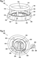
Figure 3 shows a perspective top view of an illustrative apparatus for connection to an anchor track or an anchor point ofFigure 2 , -
Figure 4 shows a perspective bottom view of the apparatus ofFigure 3 , -
Figure 5 shows a schematic sectional view of the apparatus ofFigure 3 and Figure 4 , -
Figure 6 shows a perspective top view of an illustrative apparatus for connection to an anchor track or an anchor point ofFigure 2 according to a first variant, -
Figure 7 shows a perspective side view of an illustrative apparatus for connection to an anchor track or an anchor point ofFigure 2 according to a second variant, -
Figure 8 shows a perspective top view of an illustrative apparatus for connection to an anchor track or an anchor point ofFigure 2 according to a third variant, and -
Figure 9 to Figure 12 show illustrative application scenarios with one or more of the apparatuses ofFigure 3 to Figure 8 . -
Figure 1 shows anaircraft 100 that is illustratively embodied as a rotorcraft and, more particularly, as a helicopter. Thus, for purposes of simplicity and clarity, theaircraft 100 is hereinafter referred to as the "helicopter 100". - Illustratively, the
helicopter 100 comprises at least onerotor system 110 that may be embodied as a multi-blade rotor system for providing lift and forward or backward thrust during operation. The at least onerotor system 110 comprises a plurality ofrotor blades rotor blades rotor head 114 to arotor shaft 115, which rotates in operation of thehelicopter 100 around an associated rotation axis. - The
helicopter 100 illustratively further comprises afuselage 120 that forms an airframe of thehelicopter 100. By way of example, thefuselage 120 is connected to a wheel-type landing gear 125 and illustratively forms arear fuselage 127. Therear fuselage 127 may be connected to atail boom 130. - The
tail boom 130 may be provided with at least onecounter-torque device 140 configured to provide counter-torque during operation, i. e. to counter the torque created by rotation of the plurality ofrotor blades rotor shaft 115, for purposes of balancing thehelicopter 100 in terms of yaw. If desired, thecounter-torque device 140 may be shrouded. - Illustratively, the at least one
counter-torque device 140 is provided at an aft section of thetail boom 130 and may have atail rotor 145. The aft section of thetail boom 130 may include afin 150. - Moreover, the
helicopter 100 may comprise acarrier element 160 which may at least cover the at least one engine of thehelicopter 100. If desired, thecarrier element 160 may further cover a transmission system of thehelicopter 100, which may include a gear box, and/or a crest of thehelicopter 100. More specifically, thecarrier element 160 may be embodied as a cowling arranged on top of thefuselage 120 of thehelicopter 100. - Furthermore, the
fuselage 120 illustratively forms acabin 170 e. g. for passengers, equipment, and/or cargo. At least thecabin 170 is provided with an associatedcabin floor 180. -
Figure 2 shows a section of thecabin floor 180 of the helicopter 1 ofFigure 1 . Illustratively, thecabin floor 180 is provided with a predetermined number of anchor tracks 182 and/or anchor points 184. The predetermined number of anchor tracks 182 and/or anchor points 184 may be embedded into thecabin floor 180 or mounted on top of thecabin floor 180. - By way of example, the predetermined number of anchor tracks 182 comprises three separate anchor tracks 210, 220, 230, which may also be referred to as "anchor rails" or "seat rails". The anchor tracks 210, 220, 230 preferably comply with the international standard AS33601A "Track and Stud Fitting for Cargo Transport Aircraft, Standard Dimensions for", set forth by SAE International. Illustratively, each one of the anchor tracks 210, 220, 230 is adapted to provide at least a plurality of attachment points on the
cabin floor 180. - Likewise, the predetermined number of anchor points 184 comprises a plurality of separate anchor points from which only three anchor points are individually labelled with the
reference signs cabin floor 180. - At this point, it should be noted that the predetermined number of anchor tracks 182 and/or anchor points 184 is only by way of example illustrated in connection with the
cabin floor 180 in thecabin 170 of thehelicopter 100 ofFigure 1 , and not for restricting the invention accordingly. Instead, respective anchor tracks and/or anchor points may likewise be provided on side walls or on a ceiling of thecabin 170 of thehelicopter 100 ofFigure 1 . - Furthermore, it should be noted that application of the present invention is not limited to the
helicopter 100 ofFigure 1 . Instead, the present invention may be applied in the complete field of aeronautics, i. e. in any type of aircraft and, more generally, in any type of vehicle or even buildings which may make use of the predetermined number of anchor tracks 182 and/or anchor points 184. -
Figure 3 shows anapparatus 300 for connection to an anchor track or an anchor point in an aircraft according to the present invention. By way of example, theapparatus 300 may be adapted for connection to one of the predetermined number of anchor tracks 182 ofFigure 2 , or one of the predetermined number of anchor points 184 ofFigure 2 , in thehelicopter 100 ofFigure 1 . - The
apparatus 300 comprises at least amain body 320, aquick fastening device 340, and at least two connecting elements. Illustratively, a plurality of connectingelements 310 is provided. By way of example, the plurality of connectingelements 310 comprises seven connectingelements - At least a first connecting element and a second connecting element and, illustratively, each one of the plurality of connecting
elements 310 is preferably attached to themain body 320 and configured for being connected to external load connecting devices, such as carabiners or snap hooks which are e. g. connected to load securing belts or nets. By way of example, an externalload connecting device 370, which is embodied as a snap hook, is connected to the connectingelement 313. - Preferably, at least one and, preferentially, each one of the plurality of connecting
elements 310 is attached to themain body 320 in an inclined position with a predetermined inclination angle (530 inFigure 5 ) relative to an anchor track or an anchor point to which theapparatus 300 is removably fastened. Thus, a respective external load connecting device is attachable to an associated one of the plurality of connectingelements 310 at a predetermined distance or height (540 inFigure 5 ) to/above the anchor track or the anchor point to which theapparatus 300 is removably fastened. - At least one and, illustratively, each one of the plurality of connecting
elements 310 may comprise a lug or an eyelet. Furthermore, at least one and, illustratively, each one of the plurality of connectingelements 310 may be rotatable on themain body 320. - The
main body 320 may be fastened removably to a given anchor track or anchor point by means of thequick fastening device 340. Therefore, thequick fastening device 340 is attached to themain body 320, e. g. by means ofsuitable fasteners 350, and configured for being removably fastened to an anchor track or an anchor point. By way of example, thesuitable fasteners 350 comprise fourscrews - More specifically, the
quick fastening device 340 may comprise manually activatable clamping means 360 which are configured for being securely clamped at an anchor track or an anchor point, e. g. using asuitable clamping lever 362. Thequick fastening device 340 is described in more detail below atFigure 4 . - Preferably, the
quick fastening device 340 is arranged in anaccommodation 325 formed in themain body 320. For instance, themain body 320 may be ring-shaped and form a ring around theaccommodation 325. Illustratively, the ring-shapedmain body 320 comprises at least one mounting interface for attachment of at least one connecting element of the plurality of connectingelements 310. Preferably, a plurality of mountinginterfaces 330 is provided which illustratively comprises seven mountinginterfaces elements 310, i. e. one for each one of the connectingelements - Furthermore, an
eighth mounting interface 338 is shown for attachment of an eighth connecting element. However, illustration of the eighth connecting element is omitted to further illustrate the implementation of the eighth mountinginterface 338 and, thus, a possible implementation of each one of the mountinginterfaces -
Figure 4 shows theapparatus 300 ofFigure 3 with themain body 320, thequick fastening device 340 which is attached to themain body 320 via thesuitable fasteners 350, and the plurality of connectingelements 310 that is attached to themain body 320 via the plurality of mountinginterfaces 330. According toFigure 3 , thequick fastening device 340 comprises the manually activatable clamping means 360 with the clampinglever 362. -
Figure 4 further illustrates thequick fastening device 340 that may advantageously be implemented by any suitable conventional quick fastening device which may be fastened removably to an anchor track or an anchor point. Illustratively, thequick fastening device 340 is provided with a double stud fitting configuration, i. e. with a clampable double stud fitting 364 that interacts with the clampinglever 362. - Preferably, the
quick fastening device 340 complies with the international standard AS33601A "Track and Stud Fitting for Cargo Transport Aircraft, Standard Dimensions for", set forth by SAE International. Only by way of example, and not for limiting the invention accordingly, thequick fastening device 340 may be implemented by a QCTLO (Quick Change Track Lock) Type BP-104/80D-501 manufactured by Verbindungs-Techniken-Ruther, Tackweg 41, D-47918 Tönisvorst. Thus, a more detailed description of thequick fastening device 340 may be omitted, for brevity and conciseness. -
Figure 5 shows a functional diagram 500 for further illustrating the functionality of theapparatus 300 ofFigure 3 and Figure 4 . However, for simplicity and clarity of the drawing the functional diagram 500 is only shown with a schematically illustrated section of theapparatus 300. - More specifically, as described above the
apparatus 300 comprises themain body 320, thequick fastening device 340 with the manually activatable clamping means 360 that comprises the clampable double stud fitting 364, and the plurality of connectingelements 310 that is attached to themain body 320 via the plurality of mountinginterfaces 330. However, in the functional diagram 500 only the connectingelement 313 of the plurality of connectingelements 310 is visible and attached to themain body 320 via the mountinginterface 333 of the plurality of mountinginterfaces 330. In accordance withFigure 3 , the externalload connecting device 370 is connected to the connectingelement 313. - By way of example, the
apparatus 300 is removably fastened to theanchor point 240 provided in thecabin floor 180 ofFigure 2 by means of thequick fastening device 340 and, more particularly, by means of the clampable double stud fitting 364 of the manually activatable clamping means 360. Illustratively, the clampable double stud fitting 364 forms aforce line 510 with the mountinginterface 333 and the connectingelement 313. Theforce line 510 preferably defines a direction of atensile force 520 that may be applied by means of the externalload connecting device 370 to the connectingelement 313. - More specifically, the
force line 510 preferably forms apredetermined inclination angle 530 relative to an underside of themain body 320, i. e. relative to thecabin floor 180. Thus, the connectingelement 313 is preferably attached to themain body 320 in an inclined position with thepredetermined inclination angle 530 relative to the clampable double stud fitting 364, i. e. theanchor point 240, such that the externalload connecting device 370 is attached to the connectingelement 313 at apredetermined height 540 above theanchor point 240, i. e. above thecabin floor 180. Thus, any risk of collision of the externalload connecting device 370 with thecabin floor 180 may advantageously be avoided such that undesired abrasion or wear of thecabin floor 180 may be omitted. -
Figure 6 shows anapparatus 600 for connection to an anchor track or an anchor point in an aircraft according to the present invention. By way of example, theapparatus 600 may be adapted for connection to one of the predetermined number of anchor tracks 182 ofFigure 2 , or one of the predetermined number of anchor points 184 ofFigure 2 , in thehelicopter 100 ofFigure 1 . - In accordance with the
apparatus 300 ofFigure 3 to Figure 5 , theapparatus 600 comprises themain body 320, thequick fastening device 340 that comprises the manually activatable clamping means 360 with the clampinglever 362, and the plurality of connectingelements 310 that is attached to themain body 320 via the plurality of mountinginterfaces 330. Nevertheless, for simplicity and clarity of the drawing only the connectingelement 315 of the plurality of connectingelements 310 is visible and attached to themain body 320 via the mountinginterface 335 of the plurality of mountinginterfaces 330. - However, in contrast to the
apparatus 300 ofFigure 3 to Figure 5 themain body 320 now comprises in the apparatus 600 asupport base 620 and arotatable body 640 that is rotatably connected to thesupport base 620. Preferably, thequick fastening device 340 is attached to thesupport base 620, and the plurality of connectingelements 310, i. e. illustratively the connectingelement 315, is attached to therotatable body 640. - More specifically, the
rotatable body 640 may be connected to thesupport base 620 by means of a suitable bearing. By way of example, a ball bearing or a roller bearing may be used to connect therotatable body 640 rotatably to thesupport base 620. - The
rotatable body 640 may e. g. be secured to thesupport base 620 by means of a cover in order to avoid an undesired lifting of therotatable body 640 from thesupport base 620. Such a cover may e. g. be attached securely to thesupport base 620 via associated cover fixation means 650, for instance, via screwing. Alternatively, the cover may be replaced by a radially extending flange or collar provided on thesupport base 620, which extends at least partly over therotatable body 640. However, as illustration of a cover inFigure 6 would obstruct the view of at least thesupport base 620 as well as thequick fastening device 340 and as illustration of a collar inFigure 6 would obstruct the view of at least a part of therotatable body 640, such illustrations are omitted for simplicity and clarity of the drawing. - In addition to the cover, or alternatively, the
rotatable body 640 may be secured to thesupport base 620 by means of aconical connection interface 660 formed between therotatable body 640 and thesupport base 620, as illustrated in an enlarged detail view. More specifically, theconical connection interface 660 may be formed by aconical accommodation 662 of therotatable body 640 and a corresponding conicalouter surface 666 of thesupport base 620. -
Figure 7 shows anapparatus 700 for connection to an anchor track or an anchor point in an aircraft according to the present invention. By way of example, theapparatus 700 may be adapted for connection to one of the predetermined number of anchor tracks 182 ofFigure 2 , or one of the predetermined number of anchor points 184 ofFigure 2 , in thehelicopter 100 ofFigure 1 . - In accordance with the
apparatus 300 ofFigure 3 to Figure 5 , theapparatus 700 comprises themain body 320 with theaccommodation 325, and the plurality of mountinginterfaces 330. Nevertheless, for simplicity and clarity of the drawing illustration of thequick fastening device 340 and the plurality of connectingelements 310 that is attached to themain body 320 according toFigure 3 to Figure 5 is omitted. - However, in contrast to the
apparatus 300 ofFigure 3 to Figure 5 theapparatus 700 further comprises a connectingrail 710 that is configured for being connected to external load connecting devices such as the externalload connecting device 370 ofFigure 3 . Illustratively, the connectingrail 710 is mounted in parallel to themain body 320 via a plurality of - inFigure 7 vertically extending - mountingpillars 720. By way of example, the plurality of vertically extending mountingpillars 720 comprises four vertically extending mountingpillars pillars load connecting device 370 ofFigure 3 . -
Figure 8 shows anapparatus 800 for connection to an anchor track or an anchor point in an aircraft according to the present invention. By way of example, theapparatus 800 may be adapted for connection to one of the predetermined number of anchor tracks 182 ofFigure 2 , or one of the predetermined number of anchor points 184 ofFigure 2 , in thehelicopter 100 ofFigure 1 . - Similar to the
apparatus 300 ofFigure 3 to Figure 5 , theapparatus 800 comprises amain body 830 which comprises theaccommodation 325 for accommodation of thequick fastening device 340. However, in contrast to themain body 320 ofFigure 3 to Figure 5 themain body 830 of theapparatus 800 is illustratively not provided with the plurality of mountinginterfaces 330 and the plurality of connectingelements 310. Instead, theapparatus 800 only comprises a connectingrail 810 that is configured for being connected to external load connecting devices such as the externalload connecting device 370 ofFigure 3 . - The connecting
rail 810 is illustratively mounted to themain body 830 via a plurality of laterally extending mountingrods 820. By way of example, the plurality of laterally extending mountingrods 820 comprises four laterally extending mountingrods rods load connecting device 370 ofFigure 3 . - Illustratively, the
main body 830 has aradial direction 832. Preferably, the laterally extending mountingrods radial direction 832 of themain body 830 by apredetermined inclination angle 840, as illustrated in an additional detail view. Thepredetermined inclination angle 840 may e. g. range from 0° to 60°. -
Figure 9 to Figure 12 show different application scenarios which are enabled by use of one or more of the apparatuses ofFigure 3 to Figure 8 . Only by way of example, and not for restricting the invention thereto, the different application scenarios are described with reference to use of one or more apparatuses which are realized in accordance with theapparatus 300 ofFigure 3 to Figure 5 . -
Figure 9 shows a firstillustrative application scenario 900 with theapparatus 300 ofFigure 3 to Figure 5 . Theapparatus 300 is schematically illustrated in simplified form comprising only themain body 320 and the plurality of connectingelements 310, wherein only four separate connecting elements are shown, and wherein only the connectingelement 311 is individually labelled. - By way of example, in the first illustrative application scenario 900 a
single load 910 is connected to the connectingelement 311 by means of aload attachment 920, which may comprise an external load connecting device, e. g. the externalload connecting device 370 ofFigure 3 . Theload 910 may e. g. be a piece of equipment, a backpack or any other cargo in general. -
Figure 10 shows a secondillustrative application scenario 1000 with theapparatus 300 ofFigure 3 to Figure 5 . Theapparatus 300 is again schematically illustrated in simplified form comprising only themain body 320 and the plurality of connectingelements 310, wherein only the connectingelements - By way of example, in the second illustrative application scenario 1000 a plurality of
loads 1010 is connected to the plurality of connectingelements 310 by means of a plurality ofload attachments 1020. Each one of the plurality ofloads 1010 may e. g. be a piece of equipment, a backpack or any other cargo in general. - More specifically, a
load 1012 is connected to the connectingelement 311 by means of aload attachment 1022, aload 1014 is connected to the connectingelement 313 by means of aload attachment 1024, aload 1016 is connected to the connectingelement 315 by means of aload attachment 1026, and aload 1018 is connected to the connectingelement 317 by means of aload attachment 1028. Each one of theload attachments load connecting device 370 ofFigure 3 . -
Figure 11 shows a thirdillustrative application scenario 1100 with threeapparatuses 300 according toFigure 3 to Figure 5 . Theapparatuses 300 are again schematically illustrated in simplified form comprising respectively only themain body 320 and the plurality of connectingelements 310, wherein only the connectingelement 313 is individually labelled on the first apparatus 300 (upper left), only the connectingelements elements - By way of example, in the third
illustrative application scenario 1100 thedifferent apparatuses 300 are interconnected by means of a plurality of interconnecting means 1110 to form a chain-like arrangement similar to a so-called "daisy chain". In this thirdillustrative application scenario 1100, the plurality of interconnecting means 1110 may be used for attachment of persons, equipment, or cargo. - More specifically, first interconnecting means 1112 interconnect the connecting
elements second apparatuses 300, and second interconnecting means 1114 interconnect the connectingelements third apparatuses 300. Each one of the first and second interconnecting means 1112, 1114 may e. g. be a belt or a rope. Likewise, additional interconnecting means may be used to includeadditional apparatuses 300 into the chain-like arrangement, as illustrated with a dottedline 1120 starting from the connectingelement 315 of thethird apparatus 300. -
Figure 12 shows a fourthillustrative application scenario 1200 with fourapparatuses 300 according toFigure 3 to Figure 5 . Theapparatuses 300 are again schematically illustrated in simplified form comprising respectively only themain body 320 and the plurality of connectingelements 310, wherein only the connectingelements elements elements elements - By way of example, in the third
illustrative application scenario 1200 thedifferent apparatuses 300 are interconnected by means of a plurality ofnet edges 1210 of a net 1220. In this fourthillustrative application scenario 1200, the net 1220 may be used for securing equipment, backpacks, or cargo. Furthermore, an additional interconnection may be formed as illustrated by way of example with a dottedline 1230 starting from the connectingelement 311 of thefirst apparatus 300. - It should be noted that modifications to the above described embodiments are within the common knowledge of the person skilled in the art and, thus, also considered as being part of the present invention. For instance, at
Figure 6 it is described that therotatable body 640 is rotatably connected to thesupport base 620. However, therotatable body 640 and thesupport base 620 may e. g. be provided with suitable blocking means which enable blocking of therotatable body 640 on thesupport base 620 in a fixed position. By way of example, such blocking means may comprise at least one blocking pin that may be introduced through therotatable body 640 into thesupport base 620 for blocking therotatable body 640 on thesupport base 620 in a fixed position. The at least one blocking pin may e. g. be secured on therotatable body 640 or thesupport base 620 by means of a loss prevention cord or chain. Moreover, by providing more than one accommodation for the blocking pin in therotatable body 640 and thesupport base 620, different angular positions of therotatable body 640 relative to thesupport base 620 may be realized. - Furthermore, in
Figure 7 four vertically extending mountingpillars - Likewise, in
Figure 8 four radially extending mountingpillars - Finally, four different application scenarios are described at
Figure 9 to Figure 12 by way of example. However, it should be noted that various other application scenarios are likewise contemplated, such as e. g. any possible combination of the four described application scenarios, and so on. -
- 100 aircraft
- 110 multi-blade rotor system
- 112, 113 rotor blades
- 114 rotor head
- 115 rotor shaft
- 120 fuselage
- 125 wheel-type landing gear
- 127 rear fuselage
- 130 tail boom
- 140 counter-torque device
- 145 tail rotor
- 150 fin
- 160 cowling
- 170 cabin
- 180 cabin floor
- 182 anchor tracks
- 184 anchor points
- 210, 220, 230 individual anchor tracks
- 240, 250, 260 individual anchor points
- 300 multiple connecting elements apparatus
- 310 connecting elements
- 311, 312, 313, 314, 315, 316, 317 individual connecting elements
- 320 main body
- 325 accommodation
- 330 mounting interfaces
- 331, 332, 333, 334, 335, 336, 337, 338 individual mounting interfaces
- 340 quick fastening device
- 350 device fasteners
- 351, 352, 353, 354 individual device fasteners
- 360 clamping means
- 362 clamping lever
- 364 clampable double stud fitting
- 370 snap hook
- 500 functional diagram
- 510 force line
- 520 applied force
- 530 inclination angle
- 540 predetermined height
- 600 first alternative multiple connecting elements apparatus
- 620 support base
- 640 rotatable body
- 650 cover fixation means
- 660 conical connection interface
- 662 conical accommodation
- 666 conical outer surface
- 700 second alternative multiple connecting elements apparatus
- 710 connecting rail
- 720 mounting pillars
- 722, 724, 726, 728 individual mounting pillars
- 800 third alternative multiple connecting elements apparatus
- 810 connecting rail
- 820 mounting rods
- 822, 824, 826, 828 individual mounting rods
- 830 main body
- 840 inclination angle
- 832 radial direction
- 900 first application scenario
- 910 load
- 920 load attachment
- 1000 second application scenario
- 1010 loads
- 1012, 1014, 1016, 1018 individual loads
- 1020 load attachments
- 1022, 1024, 1026, 1028 individual load attachments
- 1100 third application scenario
- 1110 interconnecting means
- 1112, 1114 individual interconnecting means
- 1120 additional interconnection(s)
- 1200 fourth application scenario
- 1210 net edges
- 1220 net
- 1230 additional interconnection(s)
Claims (15)
- An apparatus (300) for connection to an anchor track (182) or an anchor point (184) in an aircraft (100), comprising:a main body (320);a quick fastening device (340) that is attached to the main body (320) and configured for being removably fastened to the anchor track (182) or the anchor point (184); andat least a first connecting element (311) and a second connecting element (315) which are attached to the main body (320) and configured for being connected to external load connecting devices (370).
- The apparatus (300) of claim 1, wherein the main body (320) comprises an accommodation (325), and wherein the quick fastening device (340) is arranged in the accommodation (325).
- The apparatus (300) of claim 1 or 2, wherein the quick fastening device (340) comprises manually activatable clamping means (360) which are configured for being securely clamped at the anchor track (182) or the anchor point (184).
- The apparatus (300) of any one of the preceding claims, wherein the main body (320) is ring-shaped and comprises at least a first mounting interface (331) and a second mounting interface (335) for attachment of the first connecting element (311) and the second connecting element (315).
- The apparatus (300) of any one of the preceding claims, wherein the first connecting element (311) and the second connecting element (315) are attached to the main body (320) in an inclined position with a predetermined inclination angle (530) relative to the anchor track (182) or the anchor point (184) such that external load connecting devices (370) are attachable to the first connecting element (311) and the second connecting element (315) at a predetermined height (540) above the anchor track (182) or the anchor point (184).
- The apparatus (300) of any one of the preceding claims, wherein each one of the first connecting element (311) and the second connecting element (315) comprises a lug or an eyelet.
- The apparatus (300) of any one of the preceding claims, wherein each one of the first connecting element (311) and the second connecting element (315) is rotatable on the main body (320).
- The apparatus (600) of any one of the preceding claims, wherein the main body (320) comprises a support base (620) and a rotatable body (640) that is rotatably connected to the support base (620), wherein the quick fastening device (340) is attached to the support base (620), and wherein the first connecting element and the second connecting element (315) are attached to the rotatable body (640).
- The apparatus (600) of claim 8, wherein the rotatable body (640) is secured to the support base (620) by means of a cover that is securely attached to the support base (620) via associated cover fixation means (650).
- The apparatus (600) of claim 8 or 9, wherein the rotatable body (640) is secured to the support base (620) by means of a conical connection interface (660) formed between the rotatable body (640) and the support base (620).
- The apparatus (700) of any one of the preceding claims, further comprising a connecting rail (710; 810) configured for being connected to external load connecting devices (370).
- The apparatus (700) of claim 11, wherein the connecting rail (710) is mounted to the main body (320) via vertically extending mounting pillars (722, 724, 726, 728).
- The apparatus (700) of claim 12, wherein the vertically extending mounting pillars (722, 724, 726, 728) are adapted for being connected to external load connecting devices (370).
- The apparatus (800) of claim 11, wherein the connecting rail (810) is mounted to the main body (830) via laterally extending mounting rods (822, 824, 826, 828).
- The apparatus (800) of claim 14, wherein the laterally extending mounting rods (822, 824, 826, 828) are inclined relative to a radial direction (832) of the main body (830).
Priority Applications (2)
| Application Number | Priority Date | Filing Date | Title |
|---|---|---|---|
| EP23196623.5A EP4520654A1 (en) | 2023-09-11 | 2023-09-11 | An apparatus for connection to an anchor track or an anchor point in an aircraft |
| US18/657,126 US20250083819A1 (en) | 2023-09-11 | 2024-05-07 | An apparatus for connection to an anchor track or an anchor point in an aircraft |
Applications Claiming Priority (1)
| Application Number | Priority Date | Filing Date | Title |
|---|---|---|---|
| EP23196623.5A EP4520654A1 (en) | 2023-09-11 | 2023-09-11 | An apparatus for connection to an anchor track or an anchor point in an aircraft |
Publications (1)
| Publication Number | Publication Date |
|---|---|
| EP4520654A1 true EP4520654A1 (en) | 2025-03-12 |
Family
ID=88017854
Family Applications (1)
| Application Number | Title | Priority Date | Filing Date |
|---|---|---|---|
| EP23196623.5A Pending EP4520654A1 (en) | 2023-09-11 | 2023-09-11 | An apparatus for connection to an anchor track or an anchor point in an aircraft |
Country Status (2)
| Country | Link |
|---|---|
| US (1) | US20250083819A1 (en) |
| EP (1) | EP4520654A1 (en) |
Citations (7)
| Publication number | Priority date | Publication date | Assignee | Title |
|---|---|---|---|---|
| US3282229A (en) | 1964-10-27 | 1966-11-01 | Aeroquip Corp | Anchor fitting |
| US6902365B1 (en) * | 2004-02-13 | 2005-06-07 | B E Aerospace, Inc. | Quick-release track fastener |
| WO2009106746A1 (en) | 2008-01-04 | 2009-09-03 | Airbus France | Device for attaching a piece of furniture to the floor of an aircraft |
| EP2426009A1 (en) | 2009-04-30 | 2012-03-07 | Ashimori Industry Co., Ltd. | Cargo retainer device for vehicle |
| EP2607162A2 (en) | 2011-12-20 | 2013-06-26 | allsafe Jungfalk GmbH & Co. KG | Method for producing and/or converting a fixing device for fixing cargo in a cargo space |
| US20230010694A1 (en) * | 2021-07-09 | 2023-01-12 | Valeda Company, Llc | Quick-release track fittings |
| US20230159168A1 (en) * | 2021-11-23 | 2023-05-25 | Airbus Helicopters Deutschland GmbH | Human and/or non-human cargo attachment device for use with a rotorcraft |
Family Cites Families (3)
| Publication number | Priority date | Publication date | Assignee | Title |
|---|---|---|---|---|
| US4630982A (en) * | 1985-11-27 | 1986-12-23 | The Boeing Company | Cargo tie-down system |
| US10745131B2 (en) * | 2016-10-26 | 2020-08-18 | Boost Human External Cargo Systems Inc. | Belly-mounted load beam for an aerial vehicle |
| US11691740B2 (en) * | 2020-06-09 | 2023-07-04 | The Boeing Company | Wheelchair securement system and assembly |
-
2023
- 2023-09-11 EP EP23196623.5A patent/EP4520654A1/en active Pending
-
2024
- 2024-05-07 US US18/657,126 patent/US20250083819A1/en active Pending
Patent Citations (8)
| Publication number | Priority date | Publication date | Assignee | Title |
|---|---|---|---|---|
| US3282229A (en) | 1964-10-27 | 1966-11-01 | Aeroquip Corp | Anchor fitting |
| US6902365B1 (en) * | 2004-02-13 | 2005-06-07 | B E Aerospace, Inc. | Quick-release track fastener |
| WO2009106746A1 (en) | 2008-01-04 | 2009-09-03 | Airbus France | Device for attaching a piece of furniture to the floor of an aircraft |
| EP2426009A1 (en) | 2009-04-30 | 2012-03-07 | Ashimori Industry Co., Ltd. | Cargo retainer device for vehicle |
| CN102414046A (en) * | 2009-04-30 | 2012-04-11 | 芦森工业株式会社 | Cargo retainer device for vehicle |
| EP2607162A2 (en) | 2011-12-20 | 2013-06-26 | allsafe Jungfalk GmbH & Co. KG | Method for producing and/or converting a fixing device for fixing cargo in a cargo space |
| US20230010694A1 (en) * | 2021-07-09 | 2023-01-12 | Valeda Company, Llc | Quick-release track fittings |
| US20230159168A1 (en) * | 2021-11-23 | 2023-05-25 | Airbus Helicopters Deutschland GmbH | Human and/or non-human cargo attachment device for use with a rotorcraft |
Also Published As
| Publication number | Publication date |
|---|---|
| US20250083819A1 (en) | 2025-03-13 |
Similar Documents
| Publication | Publication Date | Title |
|---|---|---|
| US10953987B2 (en) | Aircraft interior configuration with flexible use space | |
| US10023313B2 (en) | Rope suspension device with at least one rope suspension module | |
| US8944380B2 (en) | Movable fastening unit for a seat frame in an aircraft | |
| US8172184B2 (en) | Aerial transport apparatus | |
| US11352144B2 (en) | Two-piece center frame assembly | |
| US9193460B2 (en) | Method for boarding and unloading of passengers of an aircraft with reduced immobilization time of the aircraft, aircraft and air terminal for its implementation | |
| US10723448B2 (en) | Rotor blade weight system | |
| US10457376B1 (en) | Aircraft stretcher connector | |
| US8882031B2 (en) | Removable horizontal stabilizer for helicopter | |
| US20190367149A1 (en) | Puck cover | |
| US20170121008A1 (en) | Maintenance step for a helicopter | |
| CN106143872A (en) | There is the wing tip device of the folding of rotatable lock | |
| US20250083819A1 (en) | An apparatus for connection to an anchor track or an anchor point in an aircraft | |
| EP4353589B1 (en) | Offset helicopter pilot seat with centered vertical motion system | |
| EP4311773A1 (en) | Motion control system for an aircraft seat | |
| US12209634B2 (en) | Modular attachment device for insertion into a plurality of strands of a braided rope | |
| US11548415B2 (en) | Adjustable swiveling passenger seat assembly | |
| EP3708870B1 (en) | A power transmission system | |
| EP3318488B1 (en) | Rotorcraft fall protection attach points and mechanism systems | |
| EP4116538B1 (en) | A rope ladder with two braided ropes | |
| EP3556655B1 (en) | An apparatus for carrying cargo with an aircraft | |
| US11155355B2 (en) | Mounting assembly | |
| US10745147B2 (en) | Detachable cargo mirror | |
| EP4495003A1 (en) | An external cargo adapter for use with a rotorcraft | |
| US5871172A (en) | Accessory mounting assembly |
Legal Events
| Date | Code | Title | Description |
|---|---|---|---|
| PUAI | Public reference made under article 153(3) epc to a published international application that has entered the european phase |
Free format text: ORIGINAL CODE: 0009012 |
|
| STAA | Information on the status of an ep patent application or granted ep patent |
Free format text: STATUS: THE APPLICATION HAS BEEN PUBLISHED |
|
| AK | Designated contracting states |
Kind code of ref document: A1 Designated state(s): AL AT BE BG CH CY CZ DE DK EE ES FI FR GB GR HR HU IE IS IT LI LT LU LV MC ME MK MT NL NO PL PT RO RS SE SI SK SM TR |
|
| STAA | Information on the status of an ep patent application or granted ep patent |
Free format text: STATUS: REQUEST FOR EXAMINATION WAS MADE |
|
| 17P | Request for examination filed |
Effective date: 20250314 |
|
| P01 | Opt-out of the competence of the unified patent court (upc) registered |
Free format text: CASE NUMBER: APP_12822/2025 Effective date: 20250314 |
|
| GRAP | Despatch of communication of intention to grant a patent |
Free format text: ORIGINAL CODE: EPIDOSNIGR1 |
|
| RIC1 | Information provided on ipc code assigned before grant |
Ipc: B64C 1/18 20060101AFI20260217BHEP Ipc: B64D 11/06 20060101ALI20260217BHEP |
|
| STAA | Information on the status of an ep patent application or granted ep patent |
Free format text: STATUS: GRANT OF PATENT IS INTENDED |
|
| INTG | Intention to grant announced |
Effective date: 20260325 |
|
| GRAS | Grant fee paid |
Free format text: ORIGINAL CODE: EPIDOSNIGR3 |
|
| GRAA | (expected) grant |
Free format text: ORIGINAL CODE: 0009210 |
|
| STAA | Information on the status of an ep patent application or granted ep patent |
Free format text: STATUS: THE PATENT HAS BEEN GRANTED |