EP4520642A1 - Leaning vehicle - Google Patents
Leaning vehicle Download PDFInfo
- Publication number
- EP4520642A1 EP4520642A1 EP24164127.3A EP24164127A EP4520642A1 EP 4520642 A1 EP4520642 A1 EP 4520642A1 EP 24164127 A EP24164127 A EP 24164127A EP 4520642 A1 EP4520642 A1 EP 4520642A1
- Authority
- EP
- European Patent Office
- Prior art keywords
- front wheel
- wheel
- vehicle
- bank angle
- driving force
- Prior art date
- Legal status (The legal status is an assumption and is not a legal conclusion. Google has not performed a legal analysis and makes no representation as to the accuracy of the status listed.)
- Granted
Links
Images









Classifications
-
- B—PERFORMING OPERATIONS; TRANSPORTING
- B62—LAND VEHICLES FOR TRAVELLING OTHERWISE THAN ON RAILS
- B62K—CYCLES; CYCLE FRAMES; CYCLE STEERING DEVICES; RIDER-OPERATED TERMINAL CONTROLS SPECIALLY ADAPTED FOR CYCLES; CYCLE AXLE SUSPENSIONS; CYCLE SIDECARS, FORECARS, OR THE LIKE
- B62K5/00—Cycles with handlebars, equipped with three or more main road wheels
- B62K5/02—Tricycles
- B62K5/027—Motorcycles with three wheels
-
- B—PERFORMING OPERATIONS; TRANSPORTING
- B60—VEHICLES IN GENERAL
- B60W—CONJOINT CONTROL OF VEHICLE SUB-UNITS OF DIFFERENT TYPE OR DIFFERENT FUNCTION; CONTROL SYSTEMS SPECIALLY ADAPTED FOR HYBRID VEHICLES; ROAD VEHICLE DRIVE CONTROL SYSTEMS FOR PURPOSES NOT RELATED TO THE CONTROL OF A PARTICULAR SUB-UNIT
- B60W30/00—Purposes of road vehicle drive control systems not related to the control of a particular sub-unit, e.g. of systems using conjoint control of vehicle sub-units
- B60W30/02—Control of vehicle driving stability
- B60W30/04—Control of vehicle driving stability related to roll-over prevention
-
- B—PERFORMING OPERATIONS; TRANSPORTING
- B60—VEHICLES IN GENERAL
- B60W—CONJOINT CONTROL OF VEHICLE SUB-UNITS OF DIFFERENT TYPE OR DIFFERENT FUNCTION; CONTROL SYSTEMS SPECIALLY ADAPTED FOR HYBRID VEHICLES; ROAD VEHICLE DRIVE CONTROL SYSTEMS FOR PURPOSES NOT RELATED TO THE CONTROL OF A PARTICULAR SUB-UNIT
- B60W30/00—Purposes of road vehicle drive control systems not related to the control of a particular sub-unit, e.g. of systems using conjoint control of vehicle sub-units
- B60W30/02—Control of vehicle driving stability
- B60W30/045—Improving turning performance
-
- B—PERFORMING OPERATIONS; TRANSPORTING
- B60—VEHICLES IN GENERAL
- B60W—CONJOINT CONTROL OF VEHICLE SUB-UNITS OF DIFFERENT TYPE OR DIFFERENT FUNCTION; CONTROL SYSTEMS SPECIALLY ADAPTED FOR HYBRID VEHICLES; ROAD VEHICLE DRIVE CONTROL SYSTEMS FOR PURPOSES NOT RELATED TO THE CONTROL OF A PARTICULAR SUB-UNIT
- B60W30/00—Purposes of road vehicle drive control systems not related to the control of a particular sub-unit, e.g. of systems using conjoint control of vehicle sub-units
- B60W30/18—Propelling the vehicle
- B60W30/18009—Propelling the vehicle related to particular drive situations
- B60W30/18145—Cornering
-
- B—PERFORMING OPERATIONS; TRANSPORTING
- B60—VEHICLES IN GENERAL
- B60W—CONJOINT CONTROL OF VEHICLE SUB-UNITS OF DIFFERENT TYPE OR DIFFERENT FUNCTION; CONTROL SYSTEMS SPECIALLY ADAPTED FOR HYBRID VEHICLES; ROAD VEHICLE DRIVE CONTROL SYSTEMS FOR PURPOSES NOT RELATED TO THE CONTROL OF A PARTICULAR SUB-UNIT
- B60W50/00—Details of control systems for road vehicle drive control not related to the control of a particular sub-unit, e.g. process diagnostic or vehicle driver interfaces
- B60W50/08—Interaction between the driver and the control system
- B60W50/14—Means for informing the driver, warning the driver or prompting a driver intervention
-
- B—PERFORMING OPERATIONS; TRANSPORTING
- B60—VEHICLES IN GENERAL
- B60W—CONJOINT CONTROL OF VEHICLE SUB-UNITS OF DIFFERENT TYPE OR DIFFERENT FUNCTION; CONTROL SYSTEMS SPECIALLY ADAPTED FOR HYBRID VEHICLES; ROAD VEHICLE DRIVE CONTROL SYSTEMS FOR PURPOSES NOT RELATED TO THE CONTROL OF A PARTICULAR SUB-UNIT
- B60W50/00—Details of control systems for road vehicle drive control not related to the control of a particular sub-unit, e.g. process diagnostic or vehicle driver interfaces
- B60W50/08—Interaction between the driver and the control system
- B60W50/14—Means for informing the driver, warning the driver or prompting a driver intervention
- B60W50/16—Tactile feedback to the driver, e.g. vibration or force feedback to the driver on the steering wheel or the accelerator pedal
-
- B—PERFORMING OPERATIONS; TRANSPORTING
- B62—LAND VEHICLES FOR TRAVELLING OTHERWISE THAN ON RAILS
- B62D—MOTOR VEHICLES; TRAILERS
- B62D9/00—Steering deflectable wheels not otherwise provided for
- B62D9/02—Steering deflectable wheels not otherwise provided for combined with means for inwardly inclining vehicle body on bends
-
- B—PERFORMING OPERATIONS; TRANSPORTING
- B62—LAND VEHICLES FOR TRAVELLING OTHERWISE THAN ON RAILS
- B62J—CYCLE SADDLES OR SEATS; AUXILIARY DEVICES OR ACCESSORIES SPECIALLY ADAPTED TO CYCLES AND NOT OTHERWISE PROVIDED FOR, e.g. ARTICLE CARRIERS OR CYCLE PROTECTORS
- B62J27/00—Safety equipment
-
- B—PERFORMING OPERATIONS; TRANSPORTING
- B62—LAND VEHICLES FOR TRAVELLING OTHERWISE THAN ON RAILS
- B62J—CYCLE SADDLES OR SEATS; AUXILIARY DEVICES OR ACCESSORIES SPECIALLY ADAPTED TO CYCLES AND NOT OTHERWISE PROVIDED FOR, e.g. ARTICLE CARRIERS OR CYCLE PROTECTORS
- B62J45/00—Electrical equipment arrangements specially adapted for use as accessories on cycles, not otherwise provided for
- B62J45/40—Sensor arrangements; Mounting thereof
- B62J45/41—Sensor arrangements; Mounting thereof characterised by the type of sensor
- B62J45/412—Speed sensors
-
- B—PERFORMING OPERATIONS; TRANSPORTING
- B62—LAND VEHICLES FOR TRAVELLING OTHERWISE THAN ON RAILS
- B62J—CYCLE SADDLES OR SEATS; AUXILIARY DEVICES OR ACCESSORIES SPECIALLY ADAPTED TO CYCLES AND NOT OTHERWISE PROVIDED FOR, e.g. ARTICLE CARRIERS OR CYCLE PROTECTORS
- B62J45/00—Electrical equipment arrangements specially adapted for use as accessories on cycles, not otherwise provided for
- B62J45/40—Sensor arrangements; Mounting thereof
- B62J45/41—Sensor arrangements; Mounting thereof characterised by the type of sensor
- B62J45/415—Inclination sensors
- B62J45/4151—Inclination sensors for sensing lateral inclination of the cycle
-
- B—PERFORMING OPERATIONS; TRANSPORTING
- B62—LAND VEHICLES FOR TRAVELLING OTHERWISE THAN ON RAILS
- B62J—CYCLE SADDLES OR SEATS; AUXILIARY DEVICES OR ACCESSORIES SPECIALLY ADAPTED TO CYCLES AND NOT OTHERWISE PROVIDED FOR, e.g. ARTICLE CARRIERS OR CYCLE PROTECTORS
- B62J50/00—Arrangements specially adapted for use on cycles not provided for in main groups B62J1/00 - B62J45/00
- B62J50/20—Information-providing devices
- B62J50/21—Information-providing devices intended to provide information to rider or passenger
- B62J50/22—Information-providing devices intended to provide information to rider or passenger electronic, e.g. displays
-
- B—PERFORMING OPERATIONS; TRANSPORTING
- B62—LAND VEHICLES FOR TRAVELLING OTHERWISE THAN ON RAILS
- B62K—CYCLES; CYCLE FRAMES; CYCLE STEERING DEVICES; RIDER-OPERATED TERMINAL CONTROLS SPECIALLY ADAPTED FOR CYCLES; CYCLE AXLE SUSPENSIONS; CYCLE SIDECARS, FORECARS, OR THE LIKE
- B62K21/00—Steering devices
-
- B—PERFORMING OPERATIONS; TRANSPORTING
- B62—LAND VEHICLES FOR TRAVELLING OTHERWISE THAN ON RAILS
- B62K—CYCLES; CYCLE FRAMES; CYCLE STEERING DEVICES; RIDER-OPERATED TERMINAL CONTROLS SPECIALLY ADAPTED FOR CYCLES; CYCLE AXLE SUSPENSIONS; CYCLE SIDECARS, FORECARS, OR THE LIKE
- B62K5/00—Cycles with handlebars, equipped with three or more main road wheels
- B62K5/02—Tricycles
- B62K5/05—Tricycles characterised by a single rear wheel
-
- B—PERFORMING OPERATIONS; TRANSPORTING
- B62—LAND VEHICLES FOR TRAVELLING OTHERWISE THAN ON RAILS
- B62K—CYCLES; CYCLE FRAMES; CYCLE STEERING DEVICES; RIDER-OPERATED TERMINAL CONTROLS SPECIALLY ADAPTED FOR CYCLES; CYCLE AXLE SUSPENSIONS; CYCLE SIDECARS, FORECARS, OR THE LIKE
- B62K5/00—Cycles with handlebars, equipped with three or more main road wheels
- B62K5/08—Cycles with handlebars, equipped with three or more main road wheels with steering devices acting on two or more wheels
-
- B—PERFORMING OPERATIONS; TRANSPORTING
- B62—LAND VEHICLES FOR TRAVELLING OTHERWISE THAN ON RAILS
- B62K—CYCLES; CYCLE FRAMES; CYCLE STEERING DEVICES; RIDER-OPERATED TERMINAL CONTROLS SPECIALLY ADAPTED FOR CYCLES; CYCLE AXLE SUSPENSIONS; CYCLE SIDECARS, FORECARS, OR THE LIKE
- B62K5/00—Cycles with handlebars, equipped with three or more main road wheels
- B62K5/10—Cycles with handlebars, equipped with three or more main road wheels with means for inwardly inclining the vehicle body on bends
-
- B—PERFORMING OPERATIONS; TRANSPORTING
- B62—LAND VEHICLES FOR TRAVELLING OTHERWISE THAN ON RAILS
- B62M—RIDER PROPULSION OF WHEELED VEHICLES OR SLEDGES; POWERED PROPULSION OF SLEDGES OR SINGLE-TRACK CYCLES; TRANSMISSIONS SPECIALLY ADAPTED FOR SUCH VEHICLES
- B62M23/00—Transmissions characterised by use of other elements; Other transmissions
- B62M23/02—Transmissions characterised by use of other elements; Other transmissions characterised by the use of two or more dissimilar sources of power, e.g. transmissions for hybrid motorcycles
-
- B—PERFORMING OPERATIONS; TRANSPORTING
- B60—VEHICLES IN GENERAL
- B60W—CONJOINT CONTROL OF VEHICLE SUB-UNITS OF DIFFERENT TYPE OR DIFFERENT FUNCTION; CONTROL SYSTEMS SPECIALLY ADAPTED FOR HYBRID VEHICLES; ROAD VEHICLE DRIVE CONTROL SYSTEMS FOR PURPOSES NOT RELATED TO THE CONTROL OF A PARTICULAR SUB-UNIT
- B60W30/00—Purposes of road vehicle drive control systems not related to the control of a particular sub-unit, e.g. of systems using conjoint control of vehicle sub-units
- B60W30/02—Control of vehicle driving stability
- B60W30/04—Control of vehicle driving stability related to roll-over prevention
- B60W2030/043—Control of vehicle driving stability related to roll-over prevention about the roll axis
-
- B—PERFORMING OPERATIONS; TRANSPORTING
- B60—VEHICLES IN GENERAL
- B60W—CONJOINT CONTROL OF VEHICLE SUB-UNITS OF DIFFERENT TYPE OR DIFFERENT FUNCTION; CONTROL SYSTEMS SPECIALLY ADAPTED FOR HYBRID VEHICLES; ROAD VEHICLE DRIVE CONTROL SYSTEMS FOR PURPOSES NOT RELATED TO THE CONTROL OF A PARTICULAR SUB-UNIT
- B60W50/00—Details of control systems for road vehicle drive control not related to the control of a particular sub-unit, e.g. process diagnostic or vehicle driver interfaces
- B60W50/08—Interaction between the driver and the control system
- B60W50/14—Means for informing the driver, warning the driver or prompting a driver intervention
- B60W2050/143—Alarm means
-
- B—PERFORMING OPERATIONS; TRANSPORTING
- B60—VEHICLES IN GENERAL
- B60W—CONJOINT CONTROL OF VEHICLE SUB-UNITS OF DIFFERENT TYPE OR DIFFERENT FUNCTION; CONTROL SYSTEMS SPECIALLY ADAPTED FOR HYBRID VEHICLES; ROAD VEHICLE DRIVE CONTROL SYSTEMS FOR PURPOSES NOT RELATED TO THE CONTROL OF A PARTICULAR SUB-UNIT
- B60W2300/00—Indexing codes relating to the type of vehicle
- B60W2300/34—Compact city vehicles, e.g., microcars or kei cars
- B60W2300/345—Three wheelers not including single track vehicles
-
- B—PERFORMING OPERATIONS; TRANSPORTING
- B60—VEHICLES IN GENERAL
- B60W—CONJOINT CONTROL OF VEHICLE SUB-UNITS OF DIFFERENT TYPE OR DIFFERENT FUNCTION; CONTROL SYSTEMS SPECIALLY ADAPTED FOR HYBRID VEHICLES; ROAD VEHICLE DRIVE CONTROL SYSTEMS FOR PURPOSES NOT RELATED TO THE CONTROL OF A PARTICULAR SUB-UNIT
- B60W2300/00—Indexing codes relating to the type of vehicle
- B60W2300/50—Tilting frame vehicles
Definitions
- the present invention relates to a leaning vehicle having a left front wheel and a right front wheel and a method for controlling such leaning vehicle, wherein the vehicle body frame tilts when turning left and right.
- a leaning vehicle has been known in the art that includes a left front wheel and a right front wheel, wherein the vehicle body frame tilts when turning left and right.
- the rider turns the leaning vehicle by steering the handle bar when turning left or right.
- the holding force For example, many riders prefer that the force holding the handle bar (hereinafter referred to as the holding force) remain constant during a turn.
- the holding force varies depending on the speed, the turning radius, etc., of the leaning vehicle. It is difficult to design a leaning vehicle so that the holding force is always constant regardless of speed and turning radius.
- some riders may prefer to vary the holding force during a turn depending on their preference rather than keeping it constant.
- the driving forces of the left front wheel and the right front wheel can be controlled independently of each other, it is possible to perform a control such as varying the holding force depending on the rider's preference.
- a leaning vehicle disclosed herein includes: a vehicle body frame including a head pipe; a left front wheel arranged leftward relative to the head pipe; a right front wheel arranged rightward relative to the head pipe; a steering shaft supported by the head pipe and rotatable left and right together with the left front wheel and the right front wheel; a handle bar fixed to the steering shaft and operated by a rider; a link mechanism that links together the vehicle body frame, the left front wheel and the right front wheel so that the vehicle body frame, the left front wheel and the right front wheel can tilt relative to the ground; a left in-wheel motor provided on the left front wheel; and a right in-wheel motor provided on the right front wheel.
- the left front wheel can be driven by the left in-wheel motor and the right front wheel can be driven by the right in-wheel motor.
- the driving force of the left front wheel and the driving force of the right front wheel can be controlled independently of each other.
- the leaning vehicle may include: a bank angle sensor that detects a bank angle of the vehicle body frame; and a control device communicatively connected to the bank angle sensor for controlling the left in-wheel motor and the right in-wheel motor based on the bank angle detected by the bank angle sensor.
- the driving force of the left front wheel and the driving force of the right front wheel can be controlled independently of each other based on the bank angle of the vehicle body frame.
- the control device may be configured to be capable of adjusting a difference between a driving force of the left front wheel and a driving force of the right front wheel when turning.
- control device adjusts the difference between the driving force of the left front wheel and the driving force of the right front wheel when turning, it is possible to adjust the handle bar holding force when turning.
- the leaning vehicle may include an input device operated by the rider.
- the control device may be communicatively connected to the input device for adjusting a difference between a driving force of the left front wheel and a driving force of the right front wheel when turning based on an input value to the input device by the rider.
- the rider can input the handle bar holding force to the rider's preference.
- the control device can control the holding force when turning depending on the rider's preference.
- the control device may be configured to be capable of performing a push steering control in which a driving force of the inner wheel is greater than a driving force of the outer wheel.
- the control device may be configured to be capable of performing a pull steering control in which a driving force of the inner wheel is less than a driving force of the outer wheel.
- the leaning vehicle may include: a bank angle sensor that detects a bank angle of the vehicle body frame; a vehicle speed sensor that detects a vehicle speed; and a control device communicatively connected to the bank angle sensor and the vehicle speed sensor for controlling the left in-wheel motor and the right in-wheel motor based on the bank angle and the vehicle speed.
- the driving force of the left front wheel and the driving force of the right front wheel can be controlled independently of each other based on the bank angle and the vehicle speed.
- the control device may be configured to perform a control of decreasing a driving force of the outer wheel and/or increasing a driving force of the inner wheel when the bank angle is equal to or greater than a threshold value.
- the bank angle when the bank angle is too deep when turning, the bank angle can be automatically adjusted to be shallow without the rider having to increase the handle bar holding force.
- the rider can relatively easily raise the vehicle body frame.
- the control device may be configured to perform an anti-tipping control of decreasing a driving force of the outer wheel and/or increasing a driving force of the inner wheel when the vehicle speed is equal to or greater than a first threshold value and the bank angle is equal to or greater than a second threshold value.
- the leaning vehicle may include an angular speed sensor that detects an angular speed of the bank angle of the vehicle body frame.
- the control device may be configured to perform an anti-tipping control of decreasing a driving force of the outer wheel and/or increasing a driving force of the inner wheel when the vehicle speed is equal to or greater than a first threshold value and the angular speed of the bank angle is equal to or greater than a third threshold value.
- the leaning vehicle may include a front sensor that detects an object in front.
- object includes another vehicle traveling in front of the leaning vehicle (hereinafter referred to as a preceding vehicle), a drive lane marked on the road, and the like.
- the control device may be configured to, when the front sensor detects the object and when the vehicle speed is equal to or greater than a fourth threshold value and the bank angle is less than or equal to a fifth threshold value, perform a notification control of alternating between a first state in which a driving force of the right front wheel is greater than a driving force of the left front wheel and a second state in which the driving force of the left front wheel is greater than the driving force of the right front wheel.
- the rider when it is detected that there is a predetermined object in front when the leaning vehicle is traveling at a relatively high speed, it is possible to notify the rider by alternating the first state and the second state with each other. For example, if a preceding vehicle is detected when the leaning vehicle is traveling at a relatively high speed, the rider who receives the notification can avoid collision with the preceding vehicle by decelerating, etc. If the leaning vehicle approaches the center line, it is detected that there is a center line in front. The rider who receives the notification can operate the handle bar to prevent the leaning vehicle from crossing the center line.
- FIG. 1 is a left side view of a leaning vehicle 1 according to one embodiment.
- front, rear, left, right, up and down refer to these directions as seen from a virtual rider seated on a seat 2 while the leaning vehicle 1 is standing upright on a horizontal surface with no rider and no load thereon, unless specified otherwise. Accordingly, it is referred to the vehicle front-rear direction according to the indication F ⁇ B, the vehicle up-down direction according to the indication U ⁇ D and the vehicle left-right direction according to the indication L ⁇ R in the figures with the vehicle in the upright position.
- standing upright on a horizontal surface refers to a state where a vehicle body frame 10 to be described below is not tilted relative to the horizontal surface (see FIG. 2 ).
- the designations F, B, L, R, U and D, as used in the figures, refer to front, rear, left, right, up and down, respectively.
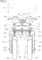
- FIG. 2 is a front view of the front portion of the leaning vehicle 1.
- FIG. 3 is a left side view of the front portion of the leaning vehicle 1.
- FIG. 4 is a plan view of the front portion of the leaning vehicle 1.
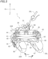
- FIG. 5 is a plan view of the front portion of the leaning vehicle 1 while steering.
- FIG. 6 is a front view of the front portion of the leaning vehicle 1 while tilting.
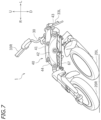
- FIG. 7 is a front view of the front portion of the leaning vehicle 1 while tilting and steering.
- the leaning vehicle 1 includes the vehicle body frame 10, the seat 2 supported by the vehicle body frame 10, a left front wheel 20L, a right front wheel 20R (see FIG. 2 ), a rear wheel 28, and a power unit 4.
- the leaning vehicle 1 includes a handle bar 30, a link mechanism 40 that links together the vehicle body frame 10, the left front wheel 20L and the right front wheel 20R, a left in-wheel motor 50L provided on the left front wheel 20L, and a right in-wheel motor 50R provided on the right front wheel 20R. Note that FIG 3 to FIG. 7 do not show the left in-wheel motor 50L and the right in-wheel motor 50R.
- the vehicle body frame 10 includes a head pipe 12 and a link pipe 14 arranged forward relative to the head pipe 12.
- the head pipe 12 supports a steering shaft 31 fixed to the handle bar 30 so that the steering shaft 31 is rotatable left and right.
- the link pipe 14 supports the steering shaft 32 so that the steering shaft 32 is rotatable left and right.
- a power unit 4 is supported by the vehicle body frame 10.
- the vehicle body frame 10 includes a power unit support portion 16 that supports the power unit 4.
- the front end portion of a rear arm 29 is connected to the power unit 4 so that a rear arm 29 is rotatable up and down.
- the rear wheel 28 is attached to the rear end portion of the rear arm 29.
- the power unit 4 is linked to the rear wheel 28.
- the power unit 4 includes a power source which is an internal combustion engine or an electric motor. The power unit 4 drives the rear wheels 28.
- the left front wheel 20L is arranged leftward relative to the head pipe 12.
- the right front wheel 20R is arranged rightward relative to the head pipe 12.
- the left front wheel 20L and the right front wheel 20R can rotate left and right together with the steering shaft 31.
- the left in-wheel motor 50L is connected to the left front wheel 20L.
- the right in-wheel motor 50R is connected to the right front wheel 20R.
- the left in-wheel motor 50L drives the left front wheel 20L and the right in-wheel motor 50R drives the right front wheel 20R.
- the leaning vehicle 1 includes a left shock-absorbing device 22L and a right shock-absorbing device 22R.
- the left shock-absorbing device 22L is a so-called telescopic shock-absorbing device.
- the left shock-absorbing device 22L includes a pair of (front and rear) telescopic elements 24.
- Each telescopic element 24 includes an outer tube 24A and an inner tube 24B inserted into the outer tube 24A.
- the right shock-absorbing device 22R is arranged in left-right symmetry with the left shock-absorbing device 22L.
- the right shock-absorbing device 22R has the same configuration as the left shock-absorbing device 22L.
- the right shock-absorbing device 22R also includes a pair of (front and rear) telescopic elements 24.
- the leaning vehicle 1 includes a left bracket 23L, a left bracket 25L, a right bracket 23R and a right bracket 25R.
- the upper end portions of the telescopic elements 24 of the left shock-absorbing device 22L are fixed to the left bracket 23L.
- the lower end portions of the telescopic elements 24 of the left shock-absorbing device 22L are fixed to the left bracket 25L.
- the left front wheel 20L is supported by the left bracket 25L.
- the upper end portions of the telescopic elements 24 of the right shock-absorbing device 22R are fixed to the right bracket 23R.
- the lower end portions of the telescopic elements 24 of the right shock-absorbing device 22R are fixed to the right bracket 25R.
- the right front wheel 20R is supported by the right bracket 25R.
- the leaning vehicle 1 includes a steering force transmission mechanism 6.
- the steering force transmission mechanism 6 includes a handle bar 30, a steering shaft 31, and a steering shaft 32 arranged forward relative to the steering shaft 31.
- the steering shaft 31 is supported by the head pipe 12 so that the steering shaft 31 is rotatable left and right.
- the steering shaft 32 is supported by the link pipe 14 so that the steering shaft 32 is rotatable left and right.
- the handle bar 30 is fixed to the steering shaft 31.
- a right grip 33R and a left grip 33L are attached to the handle bar 30.
- the right grip 33R is rotatable relative to the handle bar 30, and forms an accelerator grip for the rider to control the power unit 4.
- the steering shaft 31 and the steering shaft 32 are linked together by a link member 80.
- the link member 80 links together the steering shaft 31 and the steering shaft 32 so that they rotate together.
- the link mechanism 40 is a parallelogram link-type link mechanism. As shown in FIG. 2 , the link mechanism 40 includes an upper cross member 41, a lower cross member 42 and a lower cross member 45 (see FIG. 3 ) each extending left and right, and a left side member 43 and a right side member 44 each extending up and down.
- the link mechanism 40 is supported by the steering shaft 32, which is supported by the link pipe 14 so as to be rotatable left and right.
- the link mechanism 40 is rotatable left and right relative to the steering shaft 32 (see FIG. 5 ).
- the link mechanism 40 is configured so as not to rotate together with the steering shaft 32 even when the steering shaft 32 rotates to left and right.
- the upper cross member 41 is connected to the link pipe 14 by a link shaft 41C, to the left side member 43 by a link shaft 41L, and to the right side member 44 by a link shaft 41R.
- the upper cross member 41 is linked to the link pipe 14, the left side member 43 and the right side member 44 so that the upper cross member 41 is rotatable around an axis extending in the front-rear direction.
- the lower cross member 42 is arranged forward of the link pipe 14.
- the lower cross member 45 is arranged rearward of the link pipe 14.
- the lower cross member 42 and the lower cross member 45 are connected together by a link block 46.
- the lower cross member 42 is connected to the link pipe 14 by a link shaft 42C, to the left side member 43 by a link shaft 42L, and to the right side member 44 by a link shaft 42R.
- the lower cross member 42 is linked to the link pipe 14, the left side member 43 and the right side member 44 so that the lower cross member 42 is rotatable around an axis extending in the front-rear direction.
- a lower portion of the left side member 43 is connected to the left bracket 23L.
- the left bracket 23L is connected to the left side member 43 so that the left bracket 23L is rotatable around an axis extending in the up-down direction.
- a lower portion of the right side member 44 is connected to the right bracket 23R.
- the right bracket 23R is connected to the right side member 44 around an axis extending in the up-down direction.
- the steering force transmission mechanism 6 includes a middle transmission plate 61, a left transmission plate 62, a right transmission plate 63, a middle joint 64, a left joint 65, a right joint 66, and a tie rod 67.
- the middle transmission plate 61 is connected to the lower portion of the steering shaft 32.
- the middle transmission plate 61 extends forward from the steering shaft 32 (see FIG. 4 ).
- the left transmission plate 62 is connected to the left bracket 23L.
- the right transmission plate 63 is connected to the right bracket 23R.
- the middle joint 64 is connected to the front portion of the middle transmission plate 61.
- the middle joint 64 is connected to the middle transmission plate 61 so that the middle joint 64 is rotatable around an axis extending in the up-down direction.
- the left joint 65 is connected to the front portion of the left transmission plate 62.
- the left joint 65 is connected to the left transmission plate 62 so that the left joint 65 is rotatable around an axis extending in the up-down direction.
- the right joint 66 is connected to the front portion of the right transmission plate 63.
- the right joint 66 is connected to the right transmission plate 63 so that the right joint 66 is rotatable around an axis extending in the up-down direction.
- the tie rod 67 is connected to each of the middle joint 64, the left joint 65 and the right joint 66 so that the tie rod 67 is rotatable around an axis extending in the front-rear direction.
- the handle bar 30, the left front wheel 20L and the right front wheel 20R are linked together via the steering force transmission mechanism 6.
- the steering shaft 31 rotates to left and right.
- the left front wheel 20L and the right front wheel 20R rotate left and right, changing the direction of travel of the left front wheel 20L and the right front wheel 20R as indicated by arrows S and T.
- the vehicle body frame 10, the left front wheel 20L and right front wheel 20R are linked together via the link mechanism 40. As shown in FIG. 6 , when the rider tilts the vehicle body frame 10, the left front wheel 20L and right front wheel 20R also tilt.
- the leaning vehicle 1 includes the left in-wheel motor 50L that drives the left front wheel 20L and the right in-wheel motor 50R that drives the right front wheel 20R (see FIG. 2 ).
- the leaning vehicle 1 can control the left front wheel 20L and the right front wheel 20R independently of each other.
- the leaning vehicle 1 includes a control device 70 that controls the left in-wheel motor 50L and the right in-wheel motor 50R.
- the control device 70 is a microcomputer having a CPU 71 and a memory 72.
- the control device 70 may be separate from the control device controlling the power unit 4, or may be used also as the control device for controlling the power unit 4.
- the control device 70 is communicatively connected to the left in-wheel motor 50L and the right in-wheel motor 50R.
- the leaning vehicle 1 includes a bank angle sensor 81 that detects the bank angle of the vehicle body frame 10 (hereinafter simply referred to as the bank angle), an angular speed sensor 82 that detects the angular speed of the bank angle (hereinafter referred to as the bank angular speed), a vehicle speed sensor 83 that detects the travel speed of the leaning vehicle 1 (hereinafter referred to as the vehicle speed), and a front sensor 84 that detects an object in front of the leaning vehicle 1.
- the bank angle sensor 81, the angular speed sensor 82, the vehicle speed sensor 83 and the front sensor 84 are communicatively connected to the control device 70.
- An inertial measurement unit can be suitably used for the bank angle sensor 81.
- the bank angle sensor 81 may be, for example, a potentiometer that detects the amount of change of the link mechanism 40 (e.g., the rotation angle of the left side member 43 relative to the upper cross member 41).
- the angular speed sensor 82 may be a separate sensor from the bank angle sensor 81
- the control device 70 may detect the bank angular speed by calculating the amount of change per unit time in the bank angle detected by the bank angle sensor 81.
- the angular speed sensor 82 is composed of the bank angle sensor 81 and the control device 70.
- a camera, a millimeter wave radar, a sensor using LiDAR (Light Detection And Ranging), or an infrared sensor may be suitably used for the front sensor 84.
- the leaning vehicle 1 includes an input device 85 operated by the rider.
- the input device 85 may be arranged rearward of the handle bar 30 and forward of the seat 2.
- the leaning vehicle 1 can be controlled in various ways by controlling the drive torque of the left front wheel 20L and the right front wheel 20R.
- the input device 85 is used for applications where the rider adjusts the amount of control related to those controls.
- the input device 85 may include, for example, an input dial, a numeric keypad, an enter key, or a touch panel.
- the leaning vehicle 1 is configured as described above.
- the leaning vehicle 1 according to the present embodiment can control the drive torque of the left front wheel 20L and the drive torque of the right front wheel 20R independently of each other, allowing for a variety of controls.
- the drive torque (hereinafter simply referred to as torque) is synonymous with driving force.
- example controls that can be performed by the leaning vehicle 1 will be described.
- the first control is a control of adjusting the steering holding characteristics depending on the rider's preference.
- the steering holding characteristics are characteristics related to the force (that is, holding force) with which the rider holds the handle bar 30 while turning the leaning vehicle 1.
- FIG. 9 is a flow chart of the first control.
- step S11 it is determined whether the bank angle ⁇ detected by the bank angle sensor 81 is equal to or greater than a predetermined threshold value ⁇ min.
- a predetermined threshold value ⁇ min is set in advance to a predetermined value as the lowest bank angle ⁇ when the leaning vehicle 1 is considered to be turning.
- the threshold value ⁇ min is stored in the memory 72 of the control device 70 (see FIG. 8 ).
- step S11 it is determined whether the leaning vehicle 1 is turning or not. If the determination result of step S11 is YES, then the process proceeds to step S12. If the determination result of step S11 is NO, this control is terminated.
- step S12 the control device 70 calculates the target torques for the left front wheel 20L and the right front wheel 20R based on the information regarding the steering holding characteristics input by the rider and the driving status of the leaning vehicle 1.
- step S13 the control device 70 controls the left in-wheel motor 50L and the right in-wheel motor 50R so that the torques output by the left front wheel 20L and the right front wheel 20R become the respective target torques. Thereafter, the process returns to step S11.
- the target torques are calculated, for example, as follows.
- the control device 70 calculates the target torque TL for the left front wheel 20L and the target torque TR for the right front wheel 20R based on the input value M to the input device 85 by the rider, the vehicle speed V and the bank angle ⁇ .
- the target torques TL, TR are calculated by adding or subtracting the adjustment torque ⁇ T to or from the reference torque T0.
- the reference torque T0 is the target torque for the left front wheel 20L and the right front wheel 20R, which is determined based on the amount of operation of the accelerator grip 33R by the rider and the driving status of the leaning vehicle 1.
- the adjustment torque ⁇ T is a torque that is added or subtracted to adjust the steering holding characteristics.
- the adjustment torque ⁇ T is calculated by multiplying a predetermined torque Tm by a coefficient K.
- ⁇ T K ⁇ Tm.
- FIG. 10(a) is a graph showing the relationship between the input value M and the base factor FB.
- the input device 85 includes an input dial and an enter key
- the input value M can be changed by rotating the input dial and the input value M can be input by pressing the enter key.
- the input device 85 includes a numeric keypad and an enter key
- the input value M can be changed by pressing the numeric keypad, and the input value M can be entered by pressing the enter key.
- the input device 85 includes a touch panel
- the input value M can be changed and input by operating the touch panel. The same applies to the input of the input value M in each of the controls to be described below.
- FIG. 10(b) is a graph showing the relationship between the vehicle speed V and the speed factor Fv.
- the speed factor Fv is set so that the greater the vehicle speed V, the greater the speed factor Fv.
- FIG. 10(c) is a graph showing the relationship between the bank angle ⁇ and the bank angle factor F ⁇ .
- the bank angle factor F ⁇ is set so that the larger the bank angle ⁇ , the larger the bank angle factor F ⁇ . Note that the information shown in FIG. 10(a) to FIG. 10(c) is stored in the memory 72 of the control device 70.
- one of the left front wheel 20L and the right front wheel 20R is the outer wheel and the other is the inner wheel.
- the left front wheel 20L is the outer wheel and the right front wheel 20R is the inner wheel.
- the right front wheel 20R is the outer wheel and the left front wheel 20L is the inner wheel.
- the rider can operate the input device 85 to select either the push steering control or the pull steering control.
- a selection switch may be provided on the input device 85, and the rider may select the push steering control or the pull steering control by operating the selection switch.
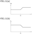
- the torque TR of the right front wheel 20R increases and the torque TL of the left front wheel 20L decreases.
- the torque of the inner wheel is greater than the torque of the outer wheel, so a leftward force is applied to the handle bar 30.
- a force in the opposite direction to the turning direction of the leaning vehicle 1 acts on the handle bar 30, thereby achieving steering holding characteristics to the rider's preference.
- the second control is a control of preventing the leaning vehicle 1 from tipping over when turning.
- FIG. 12 is a flow chart of the second control.
- step S21 it is determined whether the vehicle speed V is equal to or greater than a predetermined threshold value Vmin.
- the threshold value Vmin is an example of the "first threshold value”.
- the threshold value Vmin is set in advance to a predetermined value as the lowest vehicle speed V when the leaning vehicle 1 is considered to be traveling, and is stored in the memory 72 of the control device 70. If the determination result of step S21 is YES, the process proceeds to step S22. If the determination result of step S21 is NO, this control is terminated.
- step S22 it is determined whether the bank angle ⁇ is equal to or greater than the predetermined threshold value ⁇ t.
- the "bank angle ⁇ " in step S22 means the absolute value of the bank angle ⁇ .
- the threshold value ⁇ t is an example of the "second threshold value”.
- Step S22 is a process to determine whether the tilt of the vehicle body frame 10 is large or not. If the determination result of step S22 is YES, the anti-tipping control of step 24 is executed. If the determination result of step S22 is NO, the process proceeds to step S23.
- the "bank angular speed ⁇ " in step S23 means the absolute value of the bank angular speed ⁇ .
- the threshold value ⁇ t is an example of the "third threshold value”.
- Step S23 is a process to determine whether the speed at which the vehicle body frame 10 tilts is large or not. If the determination result of step S23 is YES, the anti-tipping control of step S24 is executed. If the determination result of step S23 is NO, there is no risk of tipping over, and this control is terminated.
- step S22 if the determination result of step S23 is YES, the process proceeds to step S24, and if the determination result of step S23 is NO, the process executes step S22.
- step S24 the process as follows is performed, for example.
- the control device 70 calculates the target torque TL for the left front wheel 20L and the target torque TR for the right front wheel 20R based on the input value M to the input device 85 by the rider, the vehicle speed V, the bank angle ⁇ and the bank angular speed ⁇ .
- the control device 70 calculates the target torques TL, TR by adding or subtracting the adjustment torque ⁇ T to or from the reference torque T0.
- the adjustment torque ⁇ T is calculated by multiplying the predetermined torque Tm by the coefficient K.
- ⁇ T K ⁇ Tm.
- FIG. 13(a) is a graph showing the relationship between the input value M and the base factor FB.
- FIG. 13(b) is a graph showing the relationship between the vehicle speed V and the speed factor Fv.
- FIG. 13(c) is a graph showing the relationship between the bank angular speed ⁇ and the bank angular speed factor P ⁇ . Note that while the bank angular speed ⁇ can take a positive or negative value, the bank angular speed ⁇ shown in FIG. 13(c) means the absolute value of the bank angular speed ⁇ .
- FIG. 13(d) is a graph showing the relationship between the bank angle ⁇ and the bank angle factor F ⁇ .
- positive/negative of the bank angle ⁇ positive is rightward and negative is leftward.
- the bank angle ⁇ takes a positive value when turning right
- the bank angle ⁇ takes a negative value when turning left.
- the information shown in FIG. 13(a) to FIG. 13(d) is stored in the memory 72 of the control device 70.
- the left front wheel 20L is the outer wheel and the right front wheel 20R is the inner wheel. Therefore, when the control device 70 adjusts the target torque TL for the left front wheel 20L and the target torque TR for the right front wheel 20R as described above, the torque of the inner wheel increases and the torque of the outer wheel decreases. Therefore, a leftward force is applied to the handle bar 30. A force in the opposite direction to the turning direction of the leaning vehicle 1 acts on the handle bar 30, and the vehicle body frame 10 is subjected to a force urging the vehicle body frame 10 to be upright. Therefore, it is possible to prevent the leaning vehicle 1 from tipping over.
- control amount factor K may be determined based on only one of the base factor FB, the speed factor Fv, the bank angular speed factor P ⁇ and the bank angle factor F ⁇ , or may be determined based on any two or three of the factors.
- the third control is a control of generating a force urging the vehicle body frame 10 to be upright when the bank angle of the vehicle body frame 10 is equal to or greater than a predetermined value while the leaning vehicle 1 is turning.
- steps S11 to S13 are executed as in the first control (see FIG. 9 ). Note however that in the third control, the processing of step S12 is different than in the first control.
- the control device 70 calculates the target torque TL for the left front wheel 20L and the target torque TR for the right front wheel 20R based on the input value M to the input device 85 by the rider, the vehicle speed V, the bank angular speed ⁇ and the bank angle ⁇ .
- the control device 70 calculates the target torques TL, TR by adding or subtracting the adjustment torque ⁇ T to or from the reference torque T0.
- the adjustment torque ⁇ T is calculated by multiplying the predetermined torque Tm by the coefficient K.
- ⁇ T K ⁇ Tm.
- the coefficient K is calculated by multiplying together the base factor FB, the speed factor Fv, the bank angular speed factor P ⁇ and the bank angle factor F ⁇ .
- K FB ⁇ Fv ⁇ F ⁇ F ⁇ .
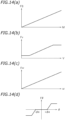
- FIG. 14(a) is a graph showing the relationship between the input value M and the base factor FB.
- FIG. 14(b) is a graph showing the relationship between the vehicle speed V and the speed factor Fv.
- FIG. 14(c) is a graph showing the relationship between the bank angular speed ⁇ and the bank angular speed factor P ⁇ . Note that while the bank angular speed ⁇ can take a positive or negative value, the bank angular speed ⁇ shown in FIG. 14(c) means the absolute value of the bank angular speed ⁇ .
- FIG. 14(d) is a graph showing the relationship between the bank angle ⁇ and the bank angle factor F ⁇ .
- positive/negative of the bank angle ⁇ positive is rightward and negative is leftward.
- the bank angle takes a positive value when turning right and the bank angle takes a negative value when turning left.
- the bank angle factor F ⁇ is zero when the bank angle ⁇ is - ⁇ a ⁇ a relative to the predetermined threshold ⁇ a. Therefore, when the absolute value of the bank angle ⁇ is relatively small, i.e., 0 ⁇
- ⁇ a, K 0, the torques of the left front wheel 20L and the right front wheel 20R are not adjusted.
- the absolute value of the bank angle ⁇ is relatively large, i.e., ⁇ a ⁇
- the left front wheel 20L is the outer wheel and the right front wheel 20R is the inner wheel. Therefore, as the control device 70 adjusts the target torque TL of the left front wheel 20L and the target torque TR of the right front wheel 20R as described above, the torque of the inner wheel is larger and the torque of the outer wheel is smaller when ⁇ a ⁇ . Therefore, a leftward force is applied to the handle bar 30. A force in the opposite direction to the turning direction of the leaning vehicle 1 acts on the handle bar 30, and the vehicle body frame 10 is subjected to a force urging the vehicle body frame 10 to be upright.
- the bank angle ⁇ when the bank angle ⁇ is relatively small (i.e., when 0 ⁇ a), no force is generated that urges the vehicle body frame 10 to be upright, and when the bank angle ⁇ is relatively large (i.e., when ⁇ a ⁇ ), a force is generated that urges the vehicle body frame 10 to be upright. Therefore, when the bank angle ⁇ is too large, the rider can relatively easily raise the vehicle body frame 10.
- the target torque is not adjusted when the bank angle ⁇ is less than a predetermined value and the target torque is adjusted when the bank angle ⁇ is equal to or greater than the predetermined value, as in the present control, the following effects can also be obtained. That is, when the bank angle ⁇ becomes equal to or greater than the predetermined value, there is a difference between the torque of the left front wheel 20L and the torque of the right front wheel 20R, thereby changing the force acting on the handle bar 30. Therefore, the rider can know that the bank angle ⁇ has become equal to or greater than the predetermined value by feeling the change in the load on the handle bar 30. For example, if the predetermined value is set to the tilt limit value, the rider can be notified of the tilt limit while the leaning vehicle 1 is turning.
- the fourth control is a control that notifies the rider when an object in front of the leaning vehicle 1 is detected.
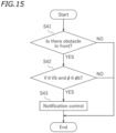
- FIG. 15 is a flow chart of the fourth control.
- step S41 it is determined from the detection result of the front sensor 84 whether there is an object such as another vehicle or a wall (hereinafter referred to as an obstacle) in front of the leaning vehicle 1.
- the notification to the rider is given when the leaning vehicle 1 is moving straight ahead and the vehicle speed is relatively high. Therefore, in step S42, it is determined whether the vehicle speed V is equal to or greater than the threshold value Vb and whether the bank angle ⁇ is less than or equal to the threshold value cpb.
- Vb is an example of the "fourth threshold value” and ⁇ b is an example of the "fifth threshold value”. If the determination result of step S42 is YES, the process proceeds to step S43, giving a notification to the rider.
- step S43 a notification control is performed to alternate between a first state in which the torque of the right front wheel 20R is greater than the torque of the left front wheel 20L and a second state in which the torque of the left front wheel 20L is greater than the torque of the right front wheel 20R. While there is no limitation on the specific process of step S43, the following process is performed, for example.
- the control device 70 calculates the target torque TL of the left front wheel 20L and the target torque TR of the right front wheel 20R based on the input value M to the input device 85 by the rider.
- the control device 70 calculates the target torques TL, TR by adding or subtracting the adjustment torque ⁇ T to or from the reference torque T0.
- the adjustment torque ⁇ T is calculated by multiplying the predetermined torque Tm by the coefficient K.
- the coefficient K is calculated by multiplying together the base factor FB, the speed factor Fv and the bank angle factor F ⁇ .
- K FB ⁇ Fv ⁇ F ⁇ .
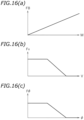
- FIG. 16(a) is a graph showing the relationship between the input value M and the base factor FB.
- FIG. 16(b) is a graph showing the relationship between the vehicle speed V and the speed factor Fv.
- FIG. 16(c) is a graph showing the relationship between the bank angle ⁇ and the bank angle factor F ⁇ . Note that while the bank angle can take a positive or negative value, the bank angle ⁇ shown in FIG. 16(c) means the absolute value of the bank angle.
- the information shown in FIG. 16(a) to FIG. 16(c) is stored in the memory 72 of the control device 70.
- FIG. 17(a), FIG. 17(b) are graphs representing the change in the adjustment torque ⁇ TR for the right front wheel 20R and the adjustment torque ⁇ TL for the left front wheel 20L, respectively.
- the torque TR of the right front wheel 20R is greater than the torque TL of the left front wheel 20L, and a leftward force is applied to the handle bar 30.
- the torque TL of the left front wheel 20L becomes greater than the torque TR of the right front wheel 20R, and a rightward force is applied to the handle bar 30. Therefore, the first state C1 and the second state C2 alternate with each other, so that a leftward load and a rightward load are alternately applied to the rider holding the handle bar 30. Thus, the rider can know that there is an obstacle in front. That is, a notification is given to the rider.
- the first state C1 and the second state C2 are not continuous, and a state in which the torques of the left front wheel 20L and the right front wheel 20R are not adjusted is interposed between the first state C1 and the second state C2.
- the rider can easily recognize that there is an obstacle in front by feeling the change in the load of the handle bar 30. Therefore, when there is an obstacle in front, it is possible to initiate, at an earlier point in time, operations such as reducing speed or avoiding obstacles.
- the front sensor 84 is used to detect whether there is an obstacle in front of the leaning vehicle 1.
- the detection target of the front sensor 84 is not limited to obstacles.
- the detection target of the front sensor 84 may be a center line on the road surface.
- the front sensor 84 may determine whether the leaning vehicle 1 is approaching the center line, and if the determination result is YES, the notification control of step S43 may be performed.
- the rider can easily grasp that the leaning vehicle 1 may possibly cross the center line.
- the rider who receives a notification can operate the handle bar 30 to prevent the leaning vehicle 1 from crossing the center line.
- Leaning vehicle 10: Vehicle body frame, 12: Head pipe, 20L: Left front wheel, 20R: Right front wheel, 30: Handle bar, 31: Steering shaft, 40: Link mechanism, 50L: Left in-wheel motor, 50R: Right in-wheel motor, 70: Control device, 81: Bank angle sensor, 82: Angular speed sensor, 83: Vehicle speed sensor, 84: Front sensor, 85: Input device
Landscapes
- Engineering & Computer Science (AREA)
- Mechanical Engineering (AREA)
- Automation & Control Theory (AREA)
- Transportation (AREA)
- Human Computer Interaction (AREA)
- Chemical & Material Sciences (AREA)
- Combustion & Propulsion (AREA)
- Automatic Cycles, And Cycles In General (AREA)
Abstract
Description
- The present invention relates to a leaning vehicle having a left front wheel and a right front wheel and a method for controlling such leaning vehicle, wherein the vehicle body frame tilts when turning left and right.
- As described in
JP 2023-51631 A - With a leaning vehicle, it is possible to enable a variety of controls if it is possible to independently change the driving forces of the left front wheel and the right front wheel.
- For example, many riders prefer that the force holding the handle bar (hereinafter referred to as the holding force) remain constant during a turn. However, the holding force varies depending on the speed, the turning radius, etc., of the leaning vehicle. It is difficult to design a leaning vehicle so that the holding force is always constant regardless of speed and turning radius. In addition, some riders may prefer to vary the holding force during a turn depending on their preference rather than keeping it constant. With conventional leaning vehicles, it is not possible to keep the holding force constant or to vary the holding force depending on to the rider's preference. However, if the driving forces of the left front wheel and the right front wheel can be controlled independently of each other, it is possible to perform a control such as varying the holding force depending on the rider's preference.
- It is an object of the present invention to provide a leaning vehicle and a method for controlling a leaning vehicle having a left front wheel arranged leftward relative to the head pipe and a right front wheel arranged rightward relative to the head pipe with regard to a vehicle left-right direction in which the driving forces of the left front wheel and the right front wheel can be controlled independently of each other. According to the present invention said object is solved by leaning vehicle having the features of
independent claim 1. Moreover, said object is solved by a method for controlling a leaning vehicle having the features ofindependent claim 12. Preferred embodiments are laid down in the dependent claims. - A leaning vehicle disclosed herein includes: a vehicle body frame including a head pipe; a left front wheel arranged leftward relative to the head pipe; a right front wheel arranged rightward relative to the head pipe; a steering shaft supported by the head pipe and rotatable left and right together with the left front wheel and the right front wheel; a handle bar fixed to the steering shaft and operated by a rider; a link mechanism that links together the vehicle body frame, the left front wheel and the right front wheel so that the vehicle body frame, the left front wheel and the right front wheel can tilt relative to the ground; a left in-wheel motor provided on the left front wheel; and a right in-wheel motor provided on the right front wheel.
- With the leaning vehicle described above, the left front wheel can be driven by the left in-wheel motor and the right front wheel can be driven by the right in-wheel motor. Thus, by controlling the left in-wheel motor and the right in-wheel motor, the driving force of the left front wheel and the driving force of the right front wheel can be controlled independently of each other.
- The leaning vehicle may include: a bank angle sensor that detects a bank angle of the vehicle body frame; and a control device communicatively connected to the bank angle sensor for controlling the left in-wheel motor and the right in-wheel motor based on the bank angle detected by the bank angle sensor.
- Thus, the driving force of the left front wheel and the driving force of the right front wheel can be controlled independently of each other based on the bank angle of the vehicle body frame.
- The control device may be configured to be capable of adjusting a difference between a driving force of the left front wheel and a driving force of the right front wheel when turning.
- Thus, as the control device adjusts the difference between the driving force of the left front wheel and the driving force of the right front wheel when turning, it is possible to adjust the handle bar holding force when turning.
- The leaning vehicle may include an input device operated by the rider. The control device may be communicatively connected to the input device for adjusting a difference between a driving force of the left front wheel and a driving force of the right front wheel when turning based on an input value to the input device by the rider.
- Thus, by operating the input device, the rider can input the handle bar holding force to the rider's preference. The control device can control the holding force when turning depending on the rider's preference.
- When the leaning vehicle turns, one of the left front wheel and the right front wheel is an outer wheel and the other one is an inner wheel. The control device may be configured to be capable of performing a push steering control in which a driving force of the inner wheel is greater than a driving force of the outer wheel.
- The control device may be configured to be capable of performing a pull steering control in which a driving force of the inner wheel is less than a driving force of the outer wheel.
- The leaning vehicle may include: a bank angle sensor that detects a bank angle of the vehicle body frame; a vehicle speed sensor that detects a vehicle speed; and a control device communicatively connected to the bank angle sensor and the vehicle speed sensor for controlling the left in-wheel motor and the right in-wheel motor based on the bank angle and the vehicle speed.
- Thus, the driving force of the left front wheel and the driving force of the right front wheel can be controlled independently of each other based on the bank angle and the vehicle speed.
- The control device may be configured to perform a control of decreasing a driving force of the outer wheel and/or increasing a driving force of the inner wheel when the bank angle is equal to or greater than a threshold value.
- Thus, when the bank angle is too deep when turning, the bank angle can be automatically adjusted to be shallow without the rider having to increase the handle bar holding force. The rider can relatively easily raise the vehicle body frame.
- The control device may be configured to perform an anti-tipping control of decreasing a driving force of the outer wheel and/or increasing a driving force of the inner wheel when the vehicle speed is equal to or greater than a first threshold value and the bank angle is equal to or greater than a second threshold value.
- Thus, it is possible to prevent the leaning vehicle from tipping over when the leaning vehicle makes a sharp turn at a relatively high speed.
- The leaning vehicle may include an angular speed sensor that detects an angular speed of the bank angle of the vehicle body frame. The control device may be configured to perform an anti-tipping control of decreasing a driving force of the outer wheel and/or increasing a driving force of the inner wheel when the vehicle speed is equal to or greater than a first threshold value and the angular speed of the bank angle is equal to or greater than a third threshold value.
- Thus, it is possible to prevent the leaning vehicle from tipping over when the leaning vehicle makes a sharp turn at a relatively high speed.
- The leaning vehicle may include a front sensor that detects an object in front. Note that the term "object" includes another vehicle traveling in front of the leaning vehicle (hereinafter referred to as a preceding vehicle), a drive lane marked on the road, and the like. The control device may be configured to, when the front sensor detects the object and when the vehicle speed is equal to or greater than a fourth threshold value and the bank angle is less than or equal to a fifth threshold value, perform a notification control of alternating between a first state in which a driving force of the right front wheel is greater than a driving force of the left front wheel and a second state in which the driving force of the left front wheel is greater than the driving force of the right front wheel.
- Thus, when it is detected that there is a predetermined object in front when the leaning vehicle is traveling at a relatively high speed, it is possible to notify the rider by alternating the first state and the second state with each other. For example, if a preceding vehicle is detected when the leaning vehicle is traveling at a relatively high speed, the rider who receives the notification can avoid collision with the preceding vehicle by decelerating, etc. If the leaning vehicle approaches the center line, it is detected that there is a center line in front. The rider who receives the notification can operate the handle bar to prevent the leaning vehicle from crossing the center line.
- According to the present invention, it is possible to provide a leaning vehicle in which the driving forces of the left front wheel and the right front wheel can be controlled independently of each other.
-
-
FIG. 1 is a left side view of a leaning vehicle according to one embodiment. -
FIG. 2 is a front view of a front portion of the leaning vehicle. -
FIG. 3 is a left side view of the front portion of the leaning vehicle. -
FIG. 4 is a plan view of the front portion of the leaning vehicle. -
FIG. 5 is a plan view of the front portion of the leaning vehicle while steering. -
FIG. 6 is a front view of the front portion of the leaning vehicle while tilting. -
FIG. 7 is a front view of the front portion of the leaning vehicle while tilting and steering. -
FIG. 8 is a block diagram of a control system of the leaning vehicle. -
FIG. 9 is a flow chart of a first control. -
FIG. 10(a) is a graph showing the relationship between the input value and the base factor for the first control.FIG. 10(b) is a graph showing the relationship between the vehicle speed and the speed factor for the first control.FIG. 10(c) is a graph showing the relationship between the bank angle and the bank angle factor for the first control. -
FIG. 11(a) is a graph showing the change in the target torque of the right front wheel for the first control.FIG. 11(b) is a graph showing the change in the target torque of the left front wheel for the first control. -
FIG. 12 is a flow chart of the second control. -
FIG. 13(a) is a graph showing the relationship between the input value and the base factor for the second control.FIG. 13(b) is a graph showing the relationship between the vehicle speed and the speed factor for the second control.FIG. 13(c) is a graph showing the relationship between the bank angular speed and the bank angular speed factor.FIG. 13(d) is a graph showing the relationship between the bank angle and the bank angle factor for the second control. -
FIG. 14(a) is a graph showing the relationship between the input value and the base factor for the third control.FIG. 14(b) is a graph showing the relationship between the vehicle speed and the speed factor for the third control.FIG. 14(c) is a graph showing the relationship between the bank angular speed and the bank angular speed factor.FIG. 14(d) is a graph showing the relationship between the bank angle and the bank angle factor for the third control. -
FIG. 15 is a flow chart of the fourth control. -
FIG. 16(a) is a graph showing the relationship between the input value and the base factor for the fourth control.FIG. 16(b) is a graph showing the relationship between the vehicle speed and the speed factor for the fourth control.FIG. 16(c) is a graph showing the relationship between the bank angle and the bank angle factor for the fourth control. -
FIG. 17(a) is a graph showing the change in the adjustment torque for the right front wheel.FIG. 17(b) is a graph showing the change in the adjustment torque for the left front wheel. - An embodiment of the leaning vehicle will now be described with reference to the drawings.
FIG. 1 is a left side view of a leaningvehicle 1 according to one embodiment. - The terms front, rear, left, right, up and down, as used in the description below, refer to these directions as seen from a virtual rider seated on a
seat 2 while the leaningvehicle 1 is standing upright on a horizontal surface with no rider and no load thereon, unless specified otherwise. Accordingly, it is referred to the vehicle front-rear direction according to the indication F↔B, the vehicle up-down direction according to the indication U↔D and the vehicle left-right direction according to the indication L↔R in the figures with the vehicle in the upright position. Note that standing upright on a horizontal surface refers to a state where avehicle body frame 10 to be described below is not tilted relative to the horizontal surface (seeFIG. 2 ). The designations F, B, L, R, U and D, as used in the figures, refer to front, rear, left, right, up and down, respectively. -
FIG. 2 is a front view of the front portion of the leaningvehicle 1.FIG. 3 is a left side view of the front portion of the leaningvehicle 1.FIG. 4 is a plan view of the front portion of the leaningvehicle 1.FIG. 5 is a plan view of the front portion of the leaningvehicle 1 while steering.FIG. 6 is a front view of the front portion of the leaningvehicle 1 while tilting.FIG. 7 is a front view of the front portion of the leaningvehicle 1 while tilting and steering. - As shown in
FIG. 1 , the leaningvehicle 1 includes thevehicle body frame 10, theseat 2 supported by thevehicle body frame 10, a leftfront wheel 20L, a rightfront wheel 20R (seeFIG. 2 ), arear wheel 28, and apower unit 4. As shown inFIG. 2 , the leaningvehicle 1 includes ahandle bar 30, alink mechanism 40 that links together thevehicle body frame 10, the leftfront wheel 20L and the rightfront wheel 20R, a left in-wheel motor 50L provided on the leftfront wheel 20L, and a right in-wheel motor 50R provided on the rightfront wheel 20R. Note thatFIG 3 to FIG. 7 do not show the left in-wheel motor 50L and the right in-wheel motor 50R. - As shown in
FIG. 4 , thevehicle body frame 10 includes ahead pipe 12 and alink pipe 14 arranged forward relative to thehead pipe 12. Thehead pipe 12 supports a steeringshaft 31 fixed to thehandle bar 30 so that the steeringshaft 31 is rotatable left and right. Thelink pipe 14 supports the steeringshaft 32 so that the steeringshaft 32 is rotatable left and right. - As shown in
FIG. 1 , apower unit 4 is supported by thevehicle body frame 10. Thevehicle body frame 10 includes a powerunit support portion 16 that supports thepower unit 4. The front end portion of arear arm 29 is connected to thepower unit 4 so that arear arm 29 is rotatable up and down. Therear wheel 28 is attached to the rear end portion of therear arm 29. Thepower unit 4 is linked to therear wheel 28. Thepower unit 4 includes a power source which is an internal combustion engine or an electric motor. Thepower unit 4 drives therear wheels 28. - As shown in
FIG. 4 , the leftfront wheel 20L is arranged leftward relative to thehead pipe 12. The rightfront wheel 20R is arranged rightward relative to thehead pipe 12. The leftfront wheel 20L and the rightfront wheel 20R can rotate left and right together with the steeringshaft 31. - As shown in
FIG. 2 , the left in-wheel motor 50L is connected to the leftfront wheel 20L. The right in-wheel motor 50R is connected to the rightfront wheel 20R. The left in-wheel motor 50L drives the leftfront wheel 20L and the right in-wheel motor 50R drives the rightfront wheel 20R. - The leaning
vehicle 1 includes a left shock-absorbingdevice 22L and a right shock-absorbingdevice 22R. As shown inFIG. 3 , the left shock-absorbingdevice 22L is a so-called telescopic shock-absorbing device. The left shock-absorbingdevice 22L includes a pair of (front and rear)telescopic elements 24. Eachtelescopic element 24 includes anouter tube 24A and aninner tube 24B inserted into theouter tube 24A. As shown inFIG. 2 , the right shock-absorbingdevice 22R is arranged in left-right symmetry with the left shock-absorbingdevice 22L. The right shock-absorbingdevice 22R has the same configuration as the left shock-absorbingdevice 22L. The right shock-absorbingdevice 22R also includes a pair of (front and rear)telescopic elements 24. - As shown in
FIG. 2 , the leaningvehicle 1 includes aleft bracket 23L, aleft bracket 25L, aright bracket 23R and aright bracket 25R. As shown inFIG. 3 , the upper end portions of thetelescopic elements 24 of the left shock-absorbingdevice 22L are fixed to theleft bracket 23L. The lower end portions of thetelescopic elements 24 of the left shock-absorbingdevice 22L are fixed to theleft bracket 25L. The leftfront wheel 20L is supported by theleft bracket 25L. As shown inFIG. 2 , the upper end portions of thetelescopic elements 24 of the right shock-absorbingdevice 22R are fixed to theright bracket 23R. The lower end portions of thetelescopic elements 24 of the right shock-absorbingdevice 22R are fixed to theright bracket 25R. The rightfront wheel 20R is supported by theright bracket 25R. - As shown in
FIG. 4 , the leaningvehicle 1 includes a steeringforce transmission mechanism 6. The steeringforce transmission mechanism 6 includes ahandle bar 30, a steeringshaft 31, and a steeringshaft 32 arranged forward relative to the steeringshaft 31. The steeringshaft 31 is supported by thehead pipe 12 so that the steeringshaft 31 is rotatable left and right. The steeringshaft 32 is supported by thelink pipe 14 so that the steeringshaft 32 is rotatable left and right. Thehandle bar 30 is fixed to the steeringshaft 31. Aright grip 33R and aleft grip 33L are attached to thehandle bar 30. Theright grip 33R is rotatable relative to thehandle bar 30, and forms an accelerator grip for the rider to control thepower unit 4. The steeringshaft 31 and the steeringshaft 32 are linked together by alink member 80. Thelink member 80 links together the steeringshaft 31 and the steeringshaft 32 so that they rotate together. - The
link mechanism 40 is a parallelogram link-type link mechanism. As shown inFIG. 2 , thelink mechanism 40 includes anupper cross member 41, alower cross member 42 and a lower cross member 45 (seeFIG. 3 ) each extending left and right, and aleft side member 43 and aright side member 44 each extending up and down. Thelink mechanism 40 is supported by the steeringshaft 32, which is supported by thelink pipe 14 so as to be rotatable left and right. Thelink mechanism 40 is rotatable left and right relative to the steering shaft 32 (seeFIG. 5 ). Thelink mechanism 40 is configured so as not to rotate together with the steeringshaft 32 even when the steeringshaft 32 rotates to left and right. - The
upper cross member 41 is connected to thelink pipe 14 by alink shaft 41C, to theleft side member 43 by alink shaft 41L, and to theright side member 44 by alink shaft 41R. Theupper cross member 41 is linked to thelink pipe 14, theleft side member 43 and theright side member 44 so that theupper cross member 41 is rotatable around an axis extending in the front-rear direction. - As shown in
FIG. 4 , thelower cross member 42 is arranged forward of thelink pipe 14. Thelower cross member 45 is arranged rearward of thelink pipe 14. Thelower cross member 42 and thelower cross member 45 are connected together by alink block 46. - As shown in
FIG. 2 , thelower cross member 42 is connected to thelink pipe 14 by alink shaft 42C, to theleft side member 43 by alink shaft 42L, and to theright side member 44 by alink shaft 42R. Thelower cross member 42 is linked to thelink pipe 14, theleft side member 43 and theright side member 44 so that thelower cross member 42 is rotatable around an axis extending in the front-rear direction. - A lower portion of the
left side member 43 is connected to theleft bracket 23L. Theleft bracket 23L is connected to theleft side member 43 so that theleft bracket 23L is rotatable around an axis extending in the up-down direction. A lower portion of theright side member 44 is connected to theright bracket 23R. Theright bracket 23R is connected to theright side member 44 around an axis extending in the up-down direction. - As shown in
FIG. 2 andFIG. 4 , the steeringforce transmission mechanism 6 includes amiddle transmission plate 61, aleft transmission plate 62, aright transmission plate 63, a middle joint 64, a left joint 65, a right joint 66, and atie rod 67. - The
middle transmission plate 61 is connected to the lower portion of the steeringshaft 32. Themiddle transmission plate 61 extends forward from the steering shaft 32 (seeFIG. 4 ). Theleft transmission plate 62 is connected to theleft bracket 23L. Theright transmission plate 63 is connected to theright bracket 23R. - As shown in
FIG. 4 , the middle joint 64 is connected to the front portion of themiddle transmission plate 61. The middle joint 64 is connected to themiddle transmission plate 61 so that the middle joint 64 is rotatable around an axis extending in the up-down direction. The left joint 65 is connected to the front portion of theleft transmission plate 62. The left joint 65 is connected to theleft transmission plate 62 so that the left joint 65 is rotatable around an axis extending in the up-down direction. The right joint 66 is connected to the front portion of theright transmission plate 63. The right joint 66 is connected to theright transmission plate 63 so that the right joint 66 is rotatable around an axis extending in the up-down direction. - The
tie rod 67 is connected to each of the middle joint 64, the left joint 65 and the right joint 66 so that thetie rod 67 is rotatable around an axis extending in the front-rear direction. - Thus, the
handle bar 30, the leftfront wheel 20L and the rightfront wheel 20R are linked together via the steeringforce transmission mechanism 6. As shown inFIG. 5 , when the rider steers thehandle bar 30, the steeringshaft 31 rotates to left and right. As the steeringshaft 31 rotates, the leftfront wheel 20L and the rightfront wheel 20R rotate left and right, changing the direction of travel of the leftfront wheel 20L and the rightfront wheel 20R as indicated by arrows S and T. - The
vehicle body frame 10, the leftfront wheel 20L and rightfront wheel 20R are linked together via thelink mechanism 40. As shown inFIG. 6 , when the rider tilts thevehicle body frame 10, the leftfront wheel 20L and rightfront wheel 20R also tilt. - As shown in
FIG. 7 , when the rider steers thehandle bar 30 and tilts thevehicle body frame 10, the leftfront wheel 20L and the rightfront wheel 20R tilt and the direction of travel is changed. - As described above, the leaning
vehicle 1 includes the left in-wheel motor 50L that drives the leftfront wheel 20L and the right in-wheel motor 50R that drives the rightfront wheel 20R (seeFIG. 2 ). The leaningvehicle 1 can control the leftfront wheel 20L and the rightfront wheel 20R independently of each other. As shown inFIG. 8 , the leaningvehicle 1 includes acontrol device 70 that controls the left in-wheel motor 50L and the right in-wheel motor 50R. Thecontrol device 70 is a microcomputer having aCPU 71 and amemory 72. Thecontrol device 70 may be separate from the control device controlling thepower unit 4, or may be used also as the control device for controlling thepower unit 4. Thecontrol device 70 is communicatively connected to the left in-wheel motor 50L and the right in-wheel motor 50R. - The leaning
vehicle 1 includes abank angle sensor 81 that detects the bank angle of the vehicle body frame 10 (hereinafter simply referred to as the bank angle), anangular speed sensor 82 that detects the angular speed of the bank angle (hereinafter referred to as the bank angular speed), avehicle speed sensor 83 that detects the travel speed of the leaning vehicle 1 (hereinafter referred to as the vehicle speed), and afront sensor 84 that detects an object in front of the leaningvehicle 1. Thebank angle sensor 81, theangular speed sensor 82, thevehicle speed sensor 83 and thefront sensor 84 are communicatively connected to thecontrol device 70. An inertial measurement unit (IMU), for example, can be suitably used for thebank angle sensor 81. Note however that there is no limitation on thebank angle sensor 81. Thebank angle sensor 81 may be, for example, a potentiometer that detects the amount of change of the link mechanism 40 (e.g., the rotation angle of theleft side member 43 relative to the upper cross member 41). While theangular speed sensor 82 may be a separate sensor from thebank angle sensor 81, thecontrol device 70 may detect the bank angular speed by calculating the amount of change per unit time in the bank angle detected by thebank angle sensor 81. In this case, theangular speed sensor 82 is composed of thebank angle sensor 81 and thecontrol device 70. A camera, a millimeter wave radar, a sensor using LiDAR (Light Detection And Ranging), or an infrared sensor may be suitably used for thefront sensor 84. - The leaning
vehicle 1 includes aninput device 85 operated by the rider. There is no particular limitation on the arrangement of theinput device 85. For example, theinput device 85 may be arranged rearward of thehandle bar 30 and forward of theseat 2. As described below, the leaningvehicle 1 can be controlled in various ways by controlling the drive torque of the leftfront wheel 20L and the rightfront wheel 20R. Theinput device 85 is used for applications where the rider adjusts the amount of control related to those controls. There is no limitation on the specific configuration of theinput device 85. Theinput device 85 may include, for example, an input dial, a numeric keypad, an enter key, or a touch panel. - The leaning
vehicle 1 is configured as described above. The leaningvehicle 1 according to the present embodiment can control the drive torque of the leftfront wheel 20L and the drive torque of the rightfront wheel 20R independently of each other, allowing for a variety of controls. Note that as used herein, the drive torque (hereinafter simply referred to as torque) is synonymous with driving force. Next, example controls that can be performed by the leaningvehicle 1 will be described. - The first control is a control of adjusting the steering holding characteristics depending on the rider's preference. Note that the steering holding characteristics are characteristics related to the force (that is, holding force) with which the rider holds the
handle bar 30 while turning the leaningvehicle 1.FIG. 9 is a flow chart of the first control. - First, in step S11, it is determined whether the bank angle ϕ detected by the
bank angle sensor 81 is equal to or greater than a predetermined threshold value ϕmin. Note that when the leaningvehicle 1 is traveling straight ahead, thevehicle body frame 10 may tilt slightly left and right. However, when the leaningvehicle 1 is traveling straight ahead, the bank angle ϕ does not become large. On the other hand, when the leaningvehicle 1 is turning, the bank angle ϕ becomes relatively large. The threshold value ϕmin is set in advance to a predetermined value as the lowest bank angle ϕ when the leaningvehicle 1 is considered to be turning. The threshold value ϕmin is stored in thememory 72 of the control device 70 (seeFIG. 8 ). In step S11, it is determined whether the leaningvehicle 1 is turning or not. If the determination result of step S11 is YES, then the process proceeds to step S12. If the determination result of step S11 is NO, this control is terminated. - In step S12, the
control device 70 calculates the target torques for the leftfront wheel 20L and the rightfront wheel 20R based on the information regarding the steering holding characteristics input by the rider and the driving status of the leaningvehicle 1. - In step S13, the
control device 70 controls the left in-wheel motor 50L and the right in-wheel motor 50R so that the torques output by the leftfront wheel 20L and the rightfront wheel 20R become the respective target torques. Thereafter, the process returns to step S11. - There is no limitation on the method of calculating the target torques in step S12. The target torques are calculated, for example, as follows. In one example of calculating the target torques, the
control device 70 calculates the target torque TL for the leftfront wheel 20L and the target torque TR for the rightfront wheel 20R based on the input value M to theinput device 85 by the rider, the vehicle speed V and the bank angle ϕ. The target torques TL, TR are calculated by adding or subtracting the adjustment torque ΔT to or from the reference torque T0. Here, the reference torque T0 is the target torque for the leftfront wheel 20L and the rightfront wheel 20R, which is determined based on the amount of operation of theaccelerator grip 33R by the rider and the driving status of the leaningvehicle 1. When the leaningvehicle 1 is traveling straight ahead, the target torque TL of the leftfront wheel 20L and the target torque TR of the rightfront wheel 20R are equal to each other, which coincides with the reference torque T0. The adjustment torque ΔT is a torque that is added or subtracted to adjust the steering holding characteristics. Here, the adjustment torque ΔT is calculated by multiplying a predetermined torque Tm by a coefficient K. ΔT = K×Tm. The coefficient K is calculated by multiplying together the base factor FB, the speed factor Fv and the bank angle factor Fϕ. That is, K = FB×Fv×Fϕ. -
FIG. 10(a) is a graph showing the relationship between the input value M and the base factor FB. Note that there is no limitation on the method of inputting the input value M to theinput device 85. For example, if theinput device 85 includes an input dial and an enter key, the input value M can be changed by rotating the input dial and the input value M can be input by pressing the enter key. If theinput device 85 includes a numeric keypad and an enter key, the input value M can be changed by pressing the numeric keypad, and the input value M can be entered by pressing the enter key. If theinput device 85 includes a touch panel, the input value M can be changed and input by operating the touch panel. The same applies to the input of the input value M in each of the controls to be described below. -
FIG. 10(b) is a graph showing the relationship between the vehicle speed V and the speed factor Fv. Here, between V1 and V2, the speed factor Fv is set so that the greater the vehicle speed V, the greater the speed factor Fv.FIG. 10(c) is a graph showing the relationship between the bank angle ϕ and the bank angle factor Fϕ. Here, between ϕ1 and ϕ2, the bank angle factor Fϕ is set so that the larger the bank angle ϕ, the larger the bank angle factor Fϕ. Note that the information shown inFIG. 10(a) to FIG. 10(c) is stored in thememory 72 of thecontrol device 70. - When the leaning
vehicle 1 turns, one of the leftfront wheel 20L and the rightfront wheel 20R is the outer wheel and the other is the inner wheel. Specifically, when the leaningvehicle 1 turns right, the leftfront wheel 20L is the outer wheel and the rightfront wheel 20R is the inner wheel. When the leaningvehicle 1 turns left, the rightfront wheel 20R is the outer wheel and the leftfront wheel 20L is the inner wheel. In the present embodiment, it is possible to perform a push steering control in which the torque of the inner wheel is greater than the torque of the outer wheel, and a pull steering control in which the torque of the inner wheel is less than the torque of the outer wheel. The rider can operate theinput device 85 to select either the push steering control or the pull steering control. For example, a selection switch may be provided on theinput device 85, and the rider may select the push steering control or the pull steering control by operating the selection switch. - If the rider selects the push steering control, for example, when the leaning
vehicle 1 turns right, thecontrol device 70 determines, as the target torque TR for the rightfront wheel 20R, a torque obtained by adding the adjustment torque ΔT to the reference torque T0, and determines, as the target torque TL for the leftfront wheel 20L, a torque obtained by subtracting the adjustment torque ΔT from the reference torque T0. That is, TR = T0+ΔT and TL = T0-ΔT. Thus, as shown inFIG. 11(a) and FIG. 11(b) , for example, after the leaningvehicle 1 starts to turn right (after time t=t1), the torque TR of the rightfront wheel 20R increases and the torque TL of the leftfront wheel 20L decreases. As a result, the torque of the inner wheel is greater than the torque of the outer wheel, so a leftward force is applied to thehandle bar 30. A force in the opposite direction to the turning direction of the leaningvehicle 1 acts on thehandle bar 30, thereby achieving steering holding characteristics to the rider's preference. - If the rider selects the pull steering control, for example, when the leaning
vehicle 1 turns right, thecontrol device 70 determines, as the target torque TR for the rightfront wheel 20R, a torque obtained by subtracting the adjustment torque ΔT from the reference torque T0, and determines, as the target torque TL for the leftfront wheel 20L, a torque obtained by adding the adjustment torque ΔT to the reference torque T0. That is, TR = T0-ΔT and TL = T0+ΔT. This causes the torque of the outer wheel to be greater than the torque of the inner wheel, thereby applying a rightward force to thehandle bar 30. A force in the same direction as the turning direction of the leaningvehicle 1 acts on thehandle bar 30, thereby achieving steering holding characteristics to the rider's preference. - The second control is a control of preventing the leaning
vehicle 1 from tipping over when turning.FIG. 12 is a flow chart of the second control. - First, in step S21, it is determined whether the vehicle speed V is equal to or greater than a predetermined threshold value Vmin. Note that the threshold value Vmin is an example of the "first threshold value". The threshold value Vmin is set in advance to a predetermined value as the lowest vehicle speed V when the leaning
vehicle 1 is considered to be traveling, and is stored in thememory 72 of thecontrol device 70. If the determination result of step S21 is YES, the process proceeds to step S22. If the determination result of step S21 is NO, this control is terminated. - In step S22, it is determined whether the bank angle ϕ is equal to or greater than the predetermined threshold value ϕt. Note that the bank angle ϕ can take a positive or negative value. The "bank angle ϕ" in step S22 means the absolute value of the bank angle ϕ. The threshold value ϕt is an example of the "second threshold value". Step S22 is a process to determine whether the tilt of the
vehicle body frame 10 is large or not. If the determination result of step S22 is YES, the anti-tipping control ofstep 24 is executed. If the determination result of step S22 is NO, the process proceeds to step S23. - In step S23, it is determined whether the bank angular speed ω = dϕ/dt is equal to or greater than the predetermined threshold value ωt. Note that the bank angular speed ω can take a positive or negative value. The "bank angular speed ω" in step S23 means the absolute value of the bank angular speed ω. The threshold value ωt is an example of the "third threshold value". Step S23 is a process to determine whether the speed at which the
vehicle body frame 10 tilts is large or not. If the determination result of step S23 is YES, the anti-tipping control of step S24 is executed. If the determination result of step S23 is NO, there is no risk of tipping over, and this control is terminated. Note that the order of step S22 and step S23 may be reversed. In this case, if the determination result of step S23 is YES, the process proceeds to step S24, and if the determination result of step S23 is NO, the process executes step S22. - While there is no limitation on the specific process of step S24, the process as follows is performed, for example. Here, the
control device 70 calculates the target torque TL for the leftfront wheel 20L and the target torque TR for the rightfront wheel 20R based on the input value M to theinput device 85 by the rider, the vehicle speed V, the bank angle ϕ and the bank angular speed ω. As in the first control example, thecontrol device 70 calculates the target torques TL, TR by adding or subtracting the adjustment torque ΔT to or from the reference torque T0. The adjustment torque ΔT is calculated by multiplying the predetermined torque Tm by the coefficient K. ΔT = K×Tm. The coefficient K is calculated by multiplying together the base factor FB, the speed factor Fv, the bank angular speed factor Pω and the bank angle factor Fϕ. That is, K = FB×Fv×Fω×Fϕ. -
FIG. 13(a) is a graph showing the relationship between the input value M and the base factor FB.FIG. 13(b) is a graph showing the relationship between the vehicle speed V and the speed factor Fv.FIG. 13(c) is a graph showing the relationship between the bank angular speed ω and the bank angular speed factor Pω. Note that while the bank angular speed ω can take a positive or negative value, the bank angular speed ω shown inFIG. 13(c) means the absolute value of the bank angular speed ω.FIG. 13(d) is a graph showing the relationship between the bank angle ϕ and the bank angle factor Fϕ. Here, regarding positive/negative of the bank angle ϕ, positive is rightward and negative is leftward. Thus, the bank angle ϕ takes a positive value when turning right, and the bank angle ϕ takes a negative value when turning left. The information shown inFIG. 13(a) to FIG. 13(d) is stored in thememory 72 of thecontrol device 70. - For example, when the leaning
vehicle 1 turns right, thecontrol device 70 determines, as the target torque TR for the rightfront wheel 20R, a torque obtained by adding the adjustment torque ΔT to the reference torque T0, and determines, as the target torque TL for the leftfront wheel 20L, a torque obtained by subtracting the adjustment torque ΔT from the reference torque T0. That is, TR = T0+ΔT and TL = T0-ΔT. When the leaningvehicle 1 turns right, the bank angle factor Fϕ is positive because the bank angle ϕ takes a positive value (seeFIG. 13(d) ), and K takes a positive value. Since ΔT = K×Tm, ΔT takes a positive value. Therefore, the target torque TR of the rightfront wheel 20R is greater than the reference torque T0, and the target torque TL of the leftfront wheel 20L is less than the reference torque T0. - When the leaning
vehicle 1 turns right, the leftfront wheel 20L is the outer wheel and the rightfront wheel 20R is the inner wheel. Therefore, when thecontrol device 70 adjusts the target torque TL for the leftfront wheel 20L and the target torque TR for the rightfront wheel 20R as described above, the torque of the inner wheel increases and the torque of the outer wheel decreases. Therefore, a leftward force is applied to thehandle bar 30. A force in the opposite direction to the turning direction of the leaningvehicle 1 acts on thehandle bar 30, and thevehicle body frame 10 is subjected to a force urging thevehicle body frame 10 to be upright. Therefore, it is possible to prevent the leaningvehicle 1 from tipping over. According to the present embodiment, the larger the bank angular speed ω is, the larger the bank angular speed factor Pω is (seeFIG. 13(c) ), and the larger the bank angle ϕ is, the larger the bank angle factor Fϕ is (seeFIG. 13(d) ). Therefore, the leaningvehicle 1 can be more reliably prevented from tipping over. - Note that the process described above regarding step S24 is only an example. The control amount factor K may be determined based on only one of the base factor FB, the speed factor Fv, the bank angular speed factor Pω and the bank angle factor Fϕ, or may be determined based on any two or three of the factors.
- The third control is a control of generating a force urging the
vehicle body frame 10 to be upright when the bank angle of thevehicle body frame 10 is equal to or greater than a predetermined value while the leaningvehicle 1 is turning. - In the third control, steps S11 to S13 are executed as in the first control (see
FIG. 9 ). Note however that in the third control, the processing of step S12 is different than in the first control. - In the third control, the following process is performed in step S12, for example. The
control device 70 calculates the target torque TL for the leftfront wheel 20L and the target torque TR for the rightfront wheel 20R based on the input value M to theinput device 85 by the rider, the vehicle speed V, the bank angular speed ω and the bank angle ϕ. Thecontrol device 70 calculates the target torques TL, TR by adding or subtracting the adjustment torque ΔT to or from the reference torque T0. The adjustment torque ΔT is calculated by multiplying the predetermined torque Tm by the coefficient K. ΔT = K×Tm. The coefficient K is calculated by multiplying together the base factor FB, the speed factor Fv, the bank angular speed factor Pω and the bank angle factor Fϕ. K = FB×Fv×Fω×Fϕ. -
FIG. 14(a) is a graph showing the relationship between the input value M and the base factor FB.FIG. 14(b) is a graph showing the relationship between the vehicle speed V and the speed factor Fv.FIG. 14(c) is a graph showing the relationship between the bank angular speed ω and the bank angular speed factor Pω. Note that while the bank angular speed ω can take a positive or negative value, the bank angular speed ω shown inFIG. 14(c) means the absolute value of the bank angular speed ω.FIG. 14(d) is a graph showing the relationship between the bank angle ϕ and the bank angle factor Fϕ. Here, regarding positive/negative of the bank angle ϕ, positive is rightward and negative is leftward. Therefore, the bank angle takes a positive value when turning right and the bank angle takes a negative value when turning left. The bank angle factor Fϕ is zero when the bank angle ϕ is -ϕa<ϕ<ϕa relative to the predetermined threshold ϕa. Therefore, when the absolute value of the bank angle ϕ is relatively small, i.e., 0<|ϕ|<ϕa, K=0, the torques of the leftfront wheel 20L and the rightfront wheel 20R are not adjusted. On the other hand, when the absolute value of the bank angle ϕ is relatively large, i.e., ϕa≤|ϕ|, K takes a positive or negative value, and the torques of the leftfront wheel 20L and the rightfront wheel 20R are adjusted. Note that the information shown inFIG. 14(a) to FIG. 14(d) is stored in thememory 72 of thecontrol device 70. - For example, when the leaning
vehicle 1 turns right, thecontrol device 70 determines, as the target torque TR of the rightfront wheel 20R, a torque obtained by adding the adjustment torque ΔT to the reference torque T0, and determines, as the target torque TL for the leftfront wheel 20L, a torque obtained by subtracting the adjustment torque ΔT from the reference torque T0. That is, TR = T0+ΔT and TL = T0-ΔT. When the leaningvehicle 1 turns right, the bank angle ϕ takes a positive value, so the bank angle factor Fϕ is positive when ϕa≤ϕ (seeFIG. 14(d) ) and K takes a positive value. Since ΔT = K×Tm, ΔT takes a positive value. Therefore, when ϕa≤ϕ, the target torque TR of the rightfront wheel 20R is greater than the reference torque T0, and the target torque TL of the leftfront wheel 20L is less than the reference torque T0. - When the leaning
vehicle 1 turns right, the leftfront wheel 20L is the outer wheel and the rightfront wheel 20R is the inner wheel. Therefore, as thecontrol device 70 adjusts the target torque TL of the leftfront wheel 20L and the target torque TR of the rightfront wheel 20R as described above, the torque of the inner wheel is larger and the torque of the outer wheel is smaller when ϕa≤ϕ. Therefore, a leftward force is applied to thehandle bar 30. A force in the opposite direction to the turning direction of the leaningvehicle 1 acts on thehandle bar 30, and thevehicle body frame 10 is subjected to a force urging thevehicle body frame 10 to be upright. According to the present embodiment, when the bank angle ϕ is relatively small (i.e., when 0<ϕ<ϕa), no force is generated that urges thevehicle body frame 10 to be upright, and when the bank angle ϕ is relatively large (i.e., when ϕa≤ϕ), a force is generated that urges thevehicle body frame 10 to be upright. Therefore, when the bank angle ϕ is too large, the rider can relatively easily raise thevehicle body frame 10. - Note that where the target torque is not adjusted when the bank angle ϕ is less than a predetermined value and the target torque is adjusted when the bank angle ϕ is equal to or greater than the predetermined value, as in the present control, the following effects can also be obtained. That is, when the bank angle ϕ becomes equal to or greater than the predetermined value, there is a difference between the torque of the left
front wheel 20L and the torque of the rightfront wheel 20R, thereby changing the force acting on thehandle bar 30. Therefore, the rider can know that the bank angle ϕ has become equal to or greater than the predetermined value by feeling the change in the load on thehandle bar 30. For example, if the predetermined value is set to the tilt limit value, the rider can be notified of the tilt limit while the leaningvehicle 1 is turning. - The fourth control is a control that notifies the rider when an object in front of the leaning
vehicle 1 is detected.FIG. 15 is a flow chart of the fourth control. - First, in step S41, it is determined from the detection result of the
front sensor 84 whether there is an object such as another vehicle or a wall (hereinafter referred to as an obstacle) in front of the leaningvehicle 1. In the present embodiment, the notification to the rider is given when the leaningvehicle 1 is moving straight ahead and the vehicle speed is relatively high. Therefore, in step S42, it is determined whether the vehicle speed V is equal to or greater than the threshold value Vb and whether the bank angle ϕ is less than or equal to the threshold value cpb. Note that Vb is an example of the "fourth threshold value" and ϕb is an example of the "fifth threshold value". If the determination result of step S42 is YES, the process proceeds to step S43, giving a notification to the rider. - In step S43, a notification control is performed to alternate between a first state in which the torque of the right
front wheel 20R is greater than the torque of the leftfront wheel 20L and a second state in which the torque of the leftfront wheel 20L is greater than the torque of the rightfront wheel 20R. While there is no limitation on the specific process of step S43, the following process is performed, for example. - The
control device 70 calculates the target torque TL of the leftfront wheel 20L and the target torque TR of the rightfront wheel 20R based on the input value M to theinput device 85 by the rider. Thecontrol device 70 calculates the target torques TL, TR by adding or subtracting the adjustment torque ΔT to or from the reference torque T0. The adjustment torque ΔT is calculated by multiplying the predetermined torque Tm by the coefficient K. Here, the coefficient K is calculated by multiplying together the base factor FB, the speed factor Fv and the bank angle factor Fϕ. K = FB×Fv×Fϕ. -
FIG. 16(a) is a graph showing the relationship between the input value M and the base factor FB.FIG. 16(b) is a graph showing the relationship between the vehicle speed V and the speed factor Fv.FIG. 16(c) is a graph showing the relationship between the bank angle ϕ and the bank angle factor Fϕ. Note that while the bank angle can take a positive or negative value, the bank angle ϕ shown inFIG. 16(c) means the absolute value of the bank angle. The information shown inFIG. 16(a) to FIG. 16(c) is stored in thememory 72 of thecontrol device 70. -
FIG. 17(a), FIG. 17(b) are graphs representing the change in the adjustment torque ΔTR for the rightfront wheel 20R and the adjustment torque ΔTL for the leftfront wheel 20L, respectively. Thecontrol device 70 alternates between the first state C1 in which ΔTR = +K×Tm and ΔTL = -K×Tm, and the second state C2 in which ΔTR = -K×Tm and ΔTL = +K×Tm. In the first state C1, the torque TR of the rightfront wheel 20R is greater than the torque TL of the leftfront wheel 20L, and a leftward force is applied to thehandle bar 30. In the second state C2, the torque TL of the leftfront wheel 20L becomes greater than the torque TR of the rightfront wheel 20R, and a rightward force is applied to thehandle bar 30. Therefore, the first state C1 and the second state C2 alternate with each other, so that a leftward load and a rightward load are alternately applied to the rider holding thehandle bar 30. Thus, the rider can know that there is an obstacle in front. That is, a notification is given to the rider. Note that in the present embodiment, the first state C1 and the second state C2 are not continuous, and a state in which the torques of the leftfront wheel 20L and the rightfront wheel 20R are not adjusted is interposed between the first state C1 and the second state C2. - According to this control, the rider can easily recognize that there is an obstacle in front by feeling the change in the load of the
handle bar 30. Therefore, when there is an obstacle in front, it is possible to initiate, at an earlier point in time, operations such as reducing speed or avoiding obstacles. - Note that in the description above, the
front sensor 84 is used to detect whether there is an obstacle in front of the leaningvehicle 1. However, the detection target of thefront sensor 84 is not limited to obstacles. For example, the detection target of thefront sensor 84 may be a center line on the road surface. For example, thefront sensor 84 may determine whether the leaningvehicle 1 is approaching the center line, and if the determination result is YES, the notification control of step S43 may be performed. In this case, the rider can easily grasp that the leaningvehicle 1 may possibly cross the center line. Thus, it is possible to alert the rider not to cross the center line. The rider who receives a notification can operate thehandle bar 30 to prevent the leaningvehicle 1 from crossing the center line. - 1: Leaning vehicle, 10: Vehicle body frame, 12: Head pipe, 20L: Left front wheel, 20R: Right front wheel, 30: Handle bar, 31: Steering shaft, 40: Link mechanism, 50L: Left in-wheel motor, 50R: Right in-wheel motor, 70: Control device, 81: Bank angle sensor, 82: Angular speed sensor, 83: Vehicle speed sensor, 84: Front sensor, 85: Input device
Claims (12)
- A leaning vehicle (1) comprising:a vehicle body frame (10) including a head pipe (12);a left front wheel (20L) arranged leftward relative to the head pipe (12) with regard to a vehicle left-right direction;a right front wheel (20R) arranged rightward relative to the head pipe (12) with regard to a vehicle left-right direction;a steering shaft (31) supported by the head pipe (12) and rotatable left and right together with the left front wheel (20L) and the right front wheel (20R);a handle bar (30) fixed to the steering shaft (31) and configured to be operated by a rider;a link mechanism (40) that links together the vehicle body frame (10), the left front wheel (20L) and the right front wheel (20R) so that the vehicle body frame (10), the left front wheel (20L) and the right front wheel (20R) can tilt relative to a ground on which the vehicle is placed;a left in-wheel motor (50L) provided on the left front wheel (20L); anda right in-wheel motor (50R) provided on the right front wheel (20R).
- The leaning vehicle (1) according to claim 1, comprising:a bank angle sensor (81) configured to detect a bank angle (ϕ) of the vehicle body frame (10); anda control device (70) communicatively connected to the bank angle sensor (81) for controlling the left in-wheel motor (50L) and the right in-wheel motor (50R) based on the bank angle (ϕ) detected by the bank angle sensor (81).
- The leaning vehicle (1) according to claim 2, wherein the control device (70) is configured to be capable of adjusting a difference between a driving force of the left front wheel (20L) and a driving force of the right front wheel (20R) when turning.
- The leaning vehicle (1) according to claim 3, comprising:an input device (85) configured to be operated by the rider,wherein the control device (70) is communicatively connected to the input device (85) for adjusting a difference between a driving force of the left front wheel (20L) and a driving force of the right front wheel (20R) when turning based on an input value to the input device (85) by the rider.
- The leaning vehicle (1) according to claim 4, wherein:when turning, one of the left front wheel (20L) and the right front wheel (20R) is an outer wheel and the other one is an inner wheel; andthe control device (70) is configured to be capable of performing a push steering control in which a driving force of the inner wheel is greater than a driving force of the outer wheel.
- The leaning vehicle (1) according to claim 4, wherein:when turning, one of the left front wheel (20L) and the right front wheel (20R) is an outer wheel and the other one is an inner wheel; andthe control device (70) is configured to be capable of performing a pull steering control in which a driving force of the inner wheel is less than a driving force of the outer wheel.
- The leaning vehicle (1) according to claim 1, comprising:a bank angle sensor (81) configured to detect a bank angle (ϕ) of the vehicle body frame (10);a vehicle speed sensor (83) configured to detect a vehicle speed (V) of the vehicle (1); anda control device (70) communicatively connected to the bank angle sensor (81) and the vehicle speed sensor (83) for controlling the left in-wheel motor (50L) and the right in-wheel motor (50R) based on the bank angle (ϕ) and the vehicle speed (V).
- The leaning vehicle (1) according to claim 7, wherein:when turning one of the left front wheel (20L) and the right front wheel (20R) is an outer wheel and the other one is an inner wheel; andthe control device (70) is configured to perform a control of decreasing a driving force of the outer wheel and/or increasing a driving force of the inner wheel when the bank angle (ϕ) is equal to or greater than a threshold value (cpmin).
- The leaning vehicle (1) according to claim 7, wherein:when turning, one of the left front wheel (20L) and the right front wheel (20R) is an outer wheel and the other one is an inner wheel; andthe control device (70) is configured to perform an anti-tipping control of decreasing a driving force of the outer wheel and/or increasing a driving force of the inner wheel when the vehicle speed (V) is equal to or greater than a first threshold value (Vmin) and the bank angle (ϕ) is equal to or greater than a second threshold value (ϕt).
- The leaning vehicle (1) according to claim 7, comprising:
an angular speed sensor (82) configured to detect a bank angular speed (ω) of changing the bank angle (ϕ) of the vehicle body frame (10), wherein:when turning, one of the left front wheel (20L) and the right front wheel (20R) is an outer wheel and the other one is an inner wheel; andthe control device (70) is configured to perform an anti-tipping control of decreasing a driving force of the outer wheel and/or increasing a driving force of the inner wheel when the vehicle speed (V) is equal to or greater than a first threshold value (Vmin) and the bank angular speed (ω) of changing the bank angle (ϕ) is equal to or greater than a third threshold value (ωt). - The leaning vehicle (1) according to claim 7, comprising:a front sensor (84) configured to detect an object in front of the vehicle,wherein the control device (70) is configured to, when the front sensor (84) detects the object in front of the vehicle and when the vehicle speed (V) is equal to or greater than a fourth threshold value (Vb) and the bank angle (ϕ) is less than or equal to a fifth threshold value (cpb), perform a notification control of alternating between a first state in which a driving force of the right front wheel (20R) is greater than a driving force of the left front wheel (20L) and a second state in which the driving force of the left front wheel (20L) is greater than the driving force of the right front wheel (20R).
- A method for controlling a leaning vehicle (1) having a left front wheel (20L) arranged leftward relative to the head pipe (12), a right front wheel (20R) arranged rightward relative to the head pipe (12) with regard to a vehicle left-right direction and a link mechanism (40) that links together a vehicle body frame (10), the left front wheel (20L) and the right front wheel (20R) so that the vehicle body frame (10), the left front wheel (20L) and the right front wheel (20R) can tilt relative to a ground on which the vehicle is placed, wherein a left in-wheel motor (50L) provided on the left front wheel (20L) and a right in-wheel motor (50R) provided on the right front wheel (20R), the method comprises:detecting a bank angle (ϕ) of the vehicle body frame (10); andcontrolling the left in-wheel motor (50L) and the right in-wheel motor (50R) based on the bank angle (ϕ) detected by the bank angle sensor (81), ordetecting a bank angle (ϕ) of the vehicle body frame (10) and detecting a vehicle speed (V) of the vehicle (1); and controlling the left in-wheel motor (50L) and the right in-wheel motor (50R) based on the bank angle (ϕ) and the vehicle speed (V).
Applications Claiming Priority (1)
| Application Number | Priority Date | Filing Date | Title |
|---|---|---|---|
| JP2023144717A JP2025037653A (en) | 2023-09-06 | 2023-09-06 | Lean Vehicle |
Publications (2)
| Publication Number | Publication Date |
|---|---|
| EP4520642A1 true EP4520642A1 (en) | 2025-03-12 |
| EP4520642B1 EP4520642B1 (en) | 2026-03-11 |
Family
ID=90365966
Family Applications (1)
| Application Number | Title | Priority Date | Filing Date |
|---|---|---|---|
| EP24164127.3A Active EP4520642B1 (en) | 2023-09-06 | 2024-03-18 | Leaning vehicle |
Country Status (2)
| Country | Link |
|---|---|
| EP (1) | EP4520642B1 (en) |
| JP (1) | JP2025037653A (en) |
Citations (5)
| Publication number | Priority date | Publication date | Assignee | Title |
|---|---|---|---|---|
| WO2017090666A1 (en) * | 2015-11-24 | 2017-06-01 | ヤマハ発動機株式会社 | Leanable vehicle |
| US20200283091A1 (en) * | 2017-11-21 | 2020-09-10 | Daido Metal Company Ltd. | Vehicle |
| FR3116261A1 (en) * | 2020-11-17 | 2022-05-20 | Furion | TURNING ASSISTANCE METHOD FOR A THREE-WHEELED VEHICLE |
| JP2022098037A (en) * | 2020-12-21 | 2022-07-01 | 大同メタル工業株式会社 | Front two-wheel tricycle |
| JP2023051631A (en) | 2021-09-30 | 2023-04-11 | ヤマハ発動機株式会社 | lean vehicle |
-
2023
- 2023-09-06 JP JP2023144717A patent/JP2025037653A/en active Pending
-
2024
- 2024-03-18 EP EP24164127.3A patent/EP4520642B1/en active Active
Patent Citations (5)
| Publication number | Priority date | Publication date | Assignee | Title |
|---|---|---|---|---|
| WO2017090666A1 (en) * | 2015-11-24 | 2017-06-01 | ヤマハ発動機株式会社 | Leanable vehicle |
| US20200283091A1 (en) * | 2017-11-21 | 2020-09-10 | Daido Metal Company Ltd. | Vehicle |
| FR3116261A1 (en) * | 2020-11-17 | 2022-05-20 | Furion | TURNING ASSISTANCE METHOD FOR A THREE-WHEELED VEHICLE |
| JP2022098037A (en) * | 2020-12-21 | 2022-07-01 | 大同メタル工業株式会社 | Front two-wheel tricycle |
| JP2023051631A (en) | 2021-09-30 | 2023-04-11 | ヤマハ発動機株式会社 | lean vehicle |
Also Published As
| Publication number | Publication date |
|---|---|
| JP2025037653A (en) | 2025-03-18 |
| EP4520642B1 (en) | 2026-03-11 |
Similar Documents
| Publication | Publication Date | Title |
|---|---|---|
| JP3911492B2 (en) | Vehicle travel support device | |
| JP3705227B2 (en) | Automatic steering device for vehicles | |
| EP2476605B1 (en) | Two-wheel vehicle, attitude stabilizing apparatus, and attitude stabilizing method | |
| JP5542094B2 (en) | Self-propelled vehicle | |
| JP4310462B2 (en) | vehicle | |
| CN100539979C (en) | Electric motor car | |
| JP6898428B2 (en) | vehicle | |
| JP2021181259A (en) | Vehicle driving support device | |
| JP2005193788A (en) | Electric power steering device for snow vehicles | |
| EP3891046B1 (en) | Self-balancing tilting vehicle with tilting speed and tilting torque controller | |
| JP2016187978A (en) | Self-propelled vehicle | |
| EP4520642A1 (en) | Leaning vehicle | |
| JP3889916B2 (en) | Steering device and steering reaction force setting method | |
| JPH0443165A (en) | Power steering device for vehicle | |
| KR101739275B1 (en) | Motor driven moving device | |
| JP2005263392A (en) | forklift | |
| JP4780178B2 (en) | vehicle | |
| JP4147854B2 (en) | Steering system | |
| JPH0714718B2 (en) | Motor control device for electric power steering device | |
| JP4888451B2 (en) | Coaxial motorcycle and control method thereof | |
| JP5082237B2 (en) | Vehicle steering assist device | |
| JP2002362390A (en) | Driving assistance devices for vehicles | |
| JP3198056B2 (en) | Cargo handling vehicle | |
| JPH054810U (en) | Two-wheeled riding management machine | |
| JP3198040B2 (en) | Cargo handling vehicle |
Legal Events
| Date | Code | Title | Description |
|---|---|---|---|
| PUAI | Public reference made under article 153(3) epc to a published international application that has entered the european phase |
Free format text: ORIGINAL CODE: 0009012 |
|
| STAA | Information on the status of an ep patent application or granted ep patent |
Free format text: STATUS: THE APPLICATION HAS BEEN PUBLISHED |
|
| AK | Designated contracting states |
Kind code of ref document: A1 Designated state(s): AL AT BE BG CH CY CZ DE DK EE ES FI FR GB GR HR HU IE IS IT LI LT LU LV MC ME MK MT NL NO PL PT RO RS SE SI SK SM TR |
|
| STAA | Information on the status of an ep patent application or granted ep patent |
Free format text: STATUS: REQUEST FOR EXAMINATION WAS MADE |
|
| P01 | Opt-out of the competence of the unified patent court (upc) registered |
Free format text: CASE NUMBER: UPC_APP_1586_4520642/2025 Effective date: 20250731 |
|
| 17P | Request for examination filed |
Effective date: 20250828 |
|
| RIC1 | Information provided on ipc code assigned before grant |
Ipc: B62K 5/10 20130101AFI20251015BHEP Ipc: B62K 5/08 20060101ALI20251015BHEP Ipc: B62K 5/027 20130101ALI20251015BHEP Ipc: B62K 5/05 20130101ALI20251015BHEP Ipc: B62K 21/00 20060101ALI20251015BHEP Ipc: B62M 23/02 20100101ALI20251015BHEP Ipc: B62J 45/412 20200101ALI20251015BHEP Ipc: B62J 45/415 20200101ALI20251015BHEP Ipc: B62J 27/00 20200101ALI20251015BHEP Ipc: B62J 50/22 20200101ALI20251015BHEP Ipc: B62D 9/02 20060101ALI20251015BHEP Ipc: B60W 30/04 20060101ALI20251015BHEP Ipc: B60W 30/045 20120101ALI20251015BHEP Ipc: B60W 30/18 20120101ALI20251015BHEP Ipc: B60W 50/14 20200101ALI20251015BHEP Ipc: B60W 50/16 20200101ALI20251015BHEP |
|
| GRAP | Despatch of communication of intention to grant a patent |
Free format text: ORIGINAL CODE: EPIDOSNIGR1 |
|
| STAA | Information on the status of an ep patent application or granted ep patent |
Free format text: STATUS: GRANT OF PATENT IS INTENDED |
|
| INTG | Intention to grant announced |
Effective date: 20251125 |
|
| GRAS | Grant fee paid |
Free format text: ORIGINAL CODE: EPIDOSNIGR3 |
|
| GRAA | (expected) grant |
Free format text: ORIGINAL CODE: 0009210 |
|
| STAA | Information on the status of an ep patent application or granted ep patent |
Free format text: STATUS: THE PATENT HAS BEEN GRANTED |
|
| AK | Designated contracting states |
Kind code of ref document: B1 Designated state(s): AL AT BE BG CH CY CZ DE DK EE ES FI FR GB GR HR HU IE IS IT LI LT LU LV MC ME MK MT NL NO PL PT RO RS SE SI SK SM TR |
|
| REG | Reference to a national code |
Ref country code: CH Ref legal event code: F10 Free format text: ST27 STATUS EVENT CODE: U-0-0-F10-F00 (AS PROVIDED BY THE NATIONAL OFFICE) Effective date: 20260311 Ref country code: GB Ref legal event code: FG4D |
|
| REG | Reference to a national code |
Ref country code: DE Ref legal event code: R096 Ref document number: 602024003053 Country of ref document: DE |
|
| REG | Reference to a national code |
Ref country code: IE Ref legal event code: FG4D |
|
| PGFP | Annual fee paid to national office [announced via postgrant information from national office to epo] |
Ref country code: DE Payment date: 20260319 Year of fee payment: 3 |
|
| PGFP | Annual fee paid to national office [announced via postgrant information from national office to epo] |
Ref country code: AT Payment date: 20260312 Year of fee payment: 3 |