EP4520615A1 - Sleeping berth structure for a vehicle sleeping compartment - Google Patents
Sleeping berth structure for a vehicle sleeping compartment Download PDFInfo
- Publication number
- EP4520615A1 EP4520615A1 EP24198092.9A EP24198092A EP4520615A1 EP 4520615 A1 EP4520615 A1 EP 4520615A1 EP 24198092 A EP24198092 A EP 24198092A EP 4520615 A1 EP4520615 A1 EP 4520615A1
- Authority
- EP
- European Patent Office
- Prior art keywords
- mounting plate
- berth
- vertical post
- horizontal beam
- sleeping
- Prior art date
- Legal status (The legal status is an assumption and is not a legal conclusion. Google has not performed a legal analysis and makes no representation as to the accuracy of the status listed.)
- Granted
Links
Images


Classifications
-
- B—PERFORMING OPERATIONS; TRANSPORTING
- B61—RAILWAYS
- B61D—BODY DETAILS OR KINDS OF RAILWAY VEHICLES
- B61D31/00—Sleeping accommodation
Definitions
- the disclosure relates to a sleeping berth structure for a vehicle sleeping compartment, such as a railway vehicle sleeping compartment.
- Long-distance vehicles such as railway vehicles, running at night usually have sleeping compartments equipped with sleeping berth structures.
- Such sleeping berth structures usually comprise a vertical post and a partition wall extending from the vertical post to a wall of the vehicle, to separate two areas of the sleeping compartment.
- a berth is generally attached to the vertical post by means of a bracket, which comprises a vertical base, screwed or welded to the vertical post and a horizontal support, welded to the base.
- the horizontal support generally consists of an L-shaped profile, the berth being supported and screwed to the horizontal section of the L-shaped profile.
- the strength of such L-shaped profile is generally not sufficient to support the weight of the berth.
- the bracket usually comprises a reinforcement arm welded to the base and to the L-shaped profile to reinforce the mechanical strength of the bracket.
- the invention relates to a sleeping berth structure for a vehicle sleeping compartment comprising:
- the frame of the first berth comprises a hollow extruded beam, and the first horizontal beam is received inside the hollow extruded beam of the frame of the first berth.
- An advantage of the invention is that the first horizontal beam is not visible to users of the berth because the first horizontal beam is received within the hollow extruded beam.
- the first horizontal beam provides sufficient strength to support the weight of the berth.
- the sleeping berth structure is thus more aesthetically pleasing.
- the bulk of the sleeping berth structure is reduced.
- risks of injury of users of the sleeping berth structure is reduced, as the berth structure presents less protruding parts.
- the sleeping berth structure comprises one or more of the following features, considered alone or according to any possible combination:
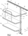
- FIG. 1 illustrates an exemplary sleeping berth structure 10.
- the sleeping berth structure 10 is intended for a vehicle sleeping compartment, such as for a railway vehicle sleeping compartment.
- the sleeping berth structure 10 comprises a vertical post 12, extending along a vertical axis Z.
- An X axis and a Y axis are also defined as two axes perpendicular to each other and to the vertical axis Z.
- the sleeping berth structure 10 comprises a partition wall 14, extending from the vertical post 12 along the X axis. Hence, the partition wall 14 extends parallel to the Z axis and to the X axis.
- the partition wall 14 extends to a side wall of the vehicle sleeping compartment, not shown, and is fixed to the side wall via a bracket 15.
- the partition wall 14 separates two areas of the sleeping compartment: a first area is located on a first side 16A of the partition wall 14, along the Y axis, and a second area is located on a second side 16B of the partition wall 14, along the Y axis.
- the vertical post 12 and the partition wall 14 extend to a rail 17.
- the rail 17 extends along the X axis and is fixed, for example, to a ceiling (not shown) of the vehicle sleeping compartment.
- the sleeping berth structure 10 comprises four berths: three berths 18A, 20A and 22A are located on the first side 16A and one berth 18B is located on the second side 16B.
- the berths 18A and 18B are aligned along the vertical axis Z.
- the berth structure 10 is intended to comprise two more berth on the second side 16B, which are not represented for the simplicity of the figures. Among these two non-represented berths, one is aligned with the berth 20A and is one aligned with the berth 22A along the vertical axis Z.
- the berths 18A and 18B are top berth, the berth 20A and the non-represented berth aligned with the berth 20A are middle berths and the berth 22A and the non-represented berth aligned with the berth 22A are bottom berths.
- Each berth 18A, 18B, 20A, 20B comprises a cushion 24 and a frame 26.
- the cushion 24 of each berth rests on the frame 26 of the berth and is preferably fixed to the frame using clips or other means of attachment.
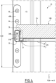
- the frame 26 of each berth 18A, 18B, 20A, 20B comprises a base 28, extending in a plane perpendicular to the vertical axis Z, and an outer hollow extruded beam 30.
- the base 28 is surrounded by the hollow extruded beam 30 and by the partition wall 14.
- the base 28 of a berth is fixed to the outer hollow extruded beam 30 of said berth with screws 31.
- the hollow extruded beam 30 has an internal opening 32 with, in the example, a rectangular cross-section.
- Each berth 18A, 18B, 20A, 20B is fixed to the vertical post 12 at one of its extremities along the X axis.
- each berth is also fixed to the side wall at the other of its extremity along the X axis.
- only the berth 18A is shown fixed to the side wall, with a bracket 33.
- the fixation of the berths 18A and 18B to the vertical post 12 is described with more details in reference to Figures 2 to 4 .
- the fixation of the two middle berths, including the berth 20A, on the one hand, and the fixation of the two bottom berths, including the berth 22A, on the other hand, to the vertical post 12 is similar to the fixation of the berths 18A and 18B to the vertical post.
- the hollow extruded beam 30 of the frame 26 of the berths extends from the vertical post 12 along the Y axis.
- the sleeping berth structure 10 comprises a first horizontal beam 34A and a second horizontal beam 34B.
- the first horizontal beam 34A is located in the first area, that is on the first side 16A of the partition wall 14, and extends from the vertical post 12 perpendicular to the partition wall 14, that is along the Y axis.
- the second horizontal beam 34B is located in the second area, that is on the second side 16B of the partition wall 14, and extends from the vertical post 12 perpendicular to the partition wall 14, that is along the Y axis.
- the first horizontal beam 34A is received inside the hollow extruded beam 30 of the frame 26 of the berth 18A, more precisely inside the internal opening 32 of the hollow extruded beam.
- the second horizontal beam 34B is received inside the hollow extruded beam 30 of the frame 26 of the berth 18B, more precisely inside the internal opening 32 of the hollow extruded beam.
- the first horizontal beam 34A and the second horizontal beam 34B have a rectangular cross-section corresponding to the cross-section of the internal opening 32 of the hollow extruded beams 30 of the berths 18A, 18B.
- the first horizontal beam 34A is fastened to the hollow extruded beam 30 of the frame 26 of the berth 18A and the second horizontal beam 34B is fastened to the hollow extruded beam 30 of the frame 26 of the berth 18B with fasteners 36, which are, in the example, screws.
- fasteners 36 which are, in the example, screws.
- the first horizontal beam 34A and the second horizontal beam 34B are securely fixed respectively to the berth 18A and to the berth 18B.
- These fixations are easy to dismount, allowing the berth 18A and the berth 18B to be separated from the vertical post 12, for example for maintenance purposes.
- the screws 36 are positioned so that they are hidden, or concealed, by the cushion 24 of the berth 18A, 18B when the cushion is placed on the frame 26.
- the sleeping berth structure 10 comprises a first mounting plate 40A, located on the first side 16A, and a second mounting plate 40B, located on the second side 16B. Both mounting plates have an elongated shape extending parallel to the partition wall 14, along the vertical post 12.
- Each of the first and second mounting plates 40A, 40B has a height H40, measured along the vertical axis Z, comprised between 100 mm and 700 mm.
- the first mounting plate 40A has an interior face 42A facing the vertical post 12 and an exterior face 44A, opposite to the vertical post and facing the first berth 18A.
- the second mounting plate 40B has an interior face 42B facing the vertical post 12 and an exterior face 44B, opposite to the vertical post and facing the second berth 18B.
- the first horizontal beam 34A is fixed to the first mounting plate 40A and the second horizontal beam 34B is fixed to the second mounting plate 40B.
- the sleeping berth structure 10 comprises two first fastening devices 46A, each having a head 48A, and two second fastening devices 46B, each having a head 48B.
- the fastening devices 46A, 46B are screws.
- first mounting plate 40A comprises two through-holes 50A
- second mounting plate 40B comprises two through-holes 50B
- first horizontal beam 34A comprises two holes 51A
- second horizontal beam 34B comprises two holes 51B, which all extend along the Y axis.
- the two first fastening devices 46A are each screwed into one of the two holes 51A of the first horizontal beam 34A, passing through one of the two through-holes 50A of the first mounting plate 40A, with their heads 48A tightened against the interior face 42A of the first mounting plate.
- the two second fastening devices 46B are each screwed into one of the two holes 51B of the second horizontal beam 34B, passing through one of the two through-holes 50B of the second mounting plate 40B, with their heads 48B tightened against the interior face 42B of the second mounting plate.
- the first and second horizontal beams 34A, 34B comprises threaded inserts, not shown, located in the holes 51A, 51B, the screws 46A, 46B being screwed in the threaded inserts.
- the first mounting plate 40A and the second mounting plate 40B are fixed together, clamping the vertical post 12 between them.
- the first mounting plate 40A comprises at least two threaded holes 52, in the example four threaded holes 52, which are blind holes, i.e. non-through holes.
- the threaded holes 52 are opened on the interior face 42A of the first mounting plate 40A and extend along the Y axis.
- the second mounting plate 40B comprises at least two countersunk through-holes 54, with the countersinks located on the exterior face 44B of the second mounting plate 40B.
- the countersunk through-holes 54 extend along the Y axis.
- the first mounting plate 40A and the second mounting plate 40B are fixed together with at least two screws 56, in the example with four screws 56.
- Each screw 56 comprises a threaded rod 58 and a countersunk head 60.
- the threaded rod 58 of each screw 56 extends through the vertical post 12 and is inserted in a countersunk through-hole 54, then through the vertical post, then screwed into one of the four threaded hole 52 of the first mounting plate 40A.
- the countersunk head 60 of each screw 56 is sitting in the countersink of one of the four through-holes 54 of the second mounting plate 40B.
- the first and second horizontal beams 34A, 34B are securely fastened to the vertical post enabling them to effectively support the weight of the berths 18A, 18B.
- screws 56 with countersunk heads 60 located in countersinks of the second mounting plate 40B is particularly advantageous because the heads of the screws do not protrude from the second mounting plate 40B, i.e. they are flush with the exterior face 44B of the second mounting plate, which is more aesthetically pleasing and avoids risks of injury. Furthermore, no screws or holes are visible on the exterior face 44A of the first mounting plate 40A, which is aesthetically pleasing.
- the vertical post 12 comprises a first recess 70A and a second recess 70B, each recess having an elongated shape extending along the vertical axis Z.
- the first mounting plate 40A is received in the first recess 70A so as not to protrude from the vertical post and the second mounting plate 40B is received in the second recess 70B so as not to protrude from the vertical post.
- the exterior faces 44A, 44B of the first and second mounting plates 40A, 40B are flush with the post 12, which is more aesthetically pleasing and avoids risks of injury.
- a height of the first recess 70A, 70B is equal to the height H40 of the first and second mounting plates 40A, 40B, apart from one assembly gap.
- the sleeping berth structure 10 comprises two straps 72, extending from the frame 26 of the berth 18A to the frame 26 of the berth 20A, to prevent a user located on the berth 20A from falling.
- the sleeping berth structure 10 comprises a rail 74, having a U-shape, extending upwards from the frame 26 of the berth 18A, to prevent a user located on the top berth 18A from falling.
- the sleeping berth structure 10 comprises a reinforcement arm 76, extending diagonally from the vertical post to the frame 26 of the berth 22A.
- the reinforcement arm 76 allows the bottom berth 22A to support more weight than the top berth 18A and the middle berth 20A, which is particularly useful as the bottom berth 22A can accommodate several users simultaneously, seated on the bottom berth.
- the heads 48A, 48B of the screws 46A, 46B are hidden in the post and are therefore not visible by users of the berths 18A, 18B, 20A, 22A.
- the first and second horizontal beams 34A, 34B are hidden in the internal opening 32 of the hollow extruded beams 30 of the berths 18A, 18B.
- the bulk of the sleeping berth structure 10 is reduced, allowing the space within the vehicle sleeping compartment to be used more efficiently.
- the positioning of ladders allowing access to the middle berth 20A and to the top berths 18A, 18B is more flexible and therefore facilitated.
- the sleeping berth structure 10 is particularly advantageous to allow easy installation and easy maintenance of the berths 18A, 18B, 20A, 22A, due to the fact that the mounting plates 40A, 40B and the horizontal beams 34A, 34B are easy to assemble and disassemble.
- the sleeping berth structure 10 is assembled solely by removable means such as screws, without welding, replacing a damaged part without replacing non-damaged parts is easy.
- the perceived quality of the sleeping berth structure 10 is increased, in comparison with known sleeping berth structure, due to the fact that a small number of screws are visible, i.e. only the heads 60 of the screws 56, which, moreover, are flush with the exterior face 44B of the second mounting plate 40B, and due to the fact that the horizontal beams 34A, 34B are not visible.
- the sleeping berth structure 10 comprises no protruding parts - such as screws -, risks of injury of users of the sleeping berth structure is reduced, particularly in the event of crash.
- the first horizontal beam 34A and/or the second horizontal beams 34B each comprises two parts hinged together: a first part is fixed to the mounting plate 40A, 40B with the screws 46A, 46B and a second part is received in the hollow extruded beam 30 of the berth 18A, 18B, 20A, 22A.
- the berth can be pivoted about an axis parallel to the X axis, so that it can be folded back against the partition 14.
- the first horizontal beam 34A and the second horizontal beams 34B are fixed respectively to the first mounting plate 40A and to the second mounting plate 40B with a number of fastening devices 46A, 46B different from two, for example with one or three fastening devices.
- first horizontal beam 34A and the second horizontal beams 34B are welded respectively to the first mounting plate 40A and to the second mounting plate 40B.
- the first horizontal beam 34A and the second horizontal beams 34B are welded to the post 12.
- the sleeping berth structure 10 does not comprises mounting plates.
Landscapes
- Engineering & Computer Science (AREA)
- Mechanical Engineering (AREA)
- Connection Of Plates (AREA)
- Combinations Of Kitchen Furniture (AREA)
Abstract
Description
- The disclosure relates to a sleeping berth structure for a vehicle sleeping compartment, such as a railway vehicle sleeping compartment.
- Long-distance vehicles, such as railway vehicles, running at night usually have sleeping compartments equipped with sleeping berth structures.
- Such sleeping berth structures usually comprise a vertical post and a partition wall extending from the vertical post to a wall of the vehicle, to separate two areas of the sleeping compartment. In known sleeping berth structures, a berth is generally attached to the vertical post by means of a bracket, which comprises a vertical base, screwed or welded to the vertical post and a horizontal support, welded to the base.
- The horizontal support generally consists of an L-shaped profile, the berth being supported and screwed to the horizontal section of the L-shaped profile. The strength of such L-shaped profile is generally not sufficient to support the weight of the berth. Thus, the bracket usually comprises a reinforcement arm welded to the base and to the L-shaped profile to reinforce the mechanical strength of the bracket.
- This type of bracket is not aesthetically pleasing, as the reinforcement arm and a large number of screws and welds are visible. In addition, a large number of screws protrudes from the bracket, posing a risk of injury.
- Therefore, there is a need for a more aesthetic and secure way to attach a berth to a vertical post.
- For this purpose, the invention relates to a sleeping berth structure for a vehicle sleeping compartment comprising:
- a vertical post,
- a partition wall, extending from the vertical post,
- a first berth, located on a first side of the partition wall, the first berth comprising a frame and a cushion, and
- a first horizontal beam, located on the first side of the partition wall and extending from the vertical post perpendicular to the partition wall to support an extremity of the first berth.
- According to the invention, the frame of the first berth comprises a hollow extruded beam, and the first horizontal beam is received inside the hollow extruded beam of the frame of the first berth.
- An advantage of the invention is that the first horizontal beam is not visible to users of the berth because the first horizontal beam is received within the hollow extruded beam. In addition, the first horizontal beam provides sufficient strength to support the weight of the berth. The sleeping berth structure is thus more aesthetically pleasing. Furthermore, the bulk of the sleeping berth structure is reduced. In addition, risks of injury of users of the sleeping berth structure is reduced, as the berth structure presents less protruding parts.
- According to advantageous aspects of the invention, the sleeping berth structure comprises one or more of the following features, considered alone or according to any possible combination:
- The first horizontal beam is fastened to the hollow extruded beam of the frame of the first berth with fasteners and the fasteners are concealed by the cushion of the first berth.
- The first horizontal beam has a rectangular cross-section.
- The sleeping berth structure further comprises a second berth, located on a second side of the partition wall opposite to the first side, the second berth comprising a frame and a cushion, and a second horizontal beam, located on the second side of the partition wall and extending from the vertical post perpendicular to the partition wall to support an extremity of the second berth. Furthermore, the frame of the second berth comprises a hollow extruded beam, the second horizontal beam is received inside the hollow extruded beam of the frame of the second berth, the first horizontal beam is fixed to a first mounting plate extending perpendicular to the first horizontal beam, the first mounting plate having an interior face, facing the vertical post, and an exterior face, opposite to the vertical post, the second horizontal beam is fixed to a second mounting plate extending perpendicular to the second horizontal beam, the second mounting plate having an interior face, facing the vertical post, and an exterior face, opposite to the vertical post, and the first mounting plate and the second mounting plate are fixed together, clamping the vertical post between them.
- The first horizontal beam is fixed to the first mounting plate with at least one first fastening device, a head of the at least one first fastening device being tightened against the interior face of the first mounting plate, and the second horizontal beam is fixed to the second mounting plate with at least one second fastening device, a head of the at least one second fastening device being tightened against the interior face of the second mounting plate.
- The first horizontal beam is fixed to the first mounting plate with two first fastening device, a head of each of the two first fastening device being tightened against the interior face of the first mounting plate, and the second horizontal beam is fixed to the second mounting plate with two second fastening device, a head of each of the two second fastening device being tightened against the interior face of the second mounting plate.
- The vertical post comprises a first recess, the first mounting plate being received in the first recess so as not to protrude from the vertical post, and the vertical post comprises a second recess, the second mounting plate being received in the second recess so as not to protrude from the vertical post.
- The first mounting plate comprises at least two blind threaded holes, opening on the interior face of the first mounting plate, the second mounting plate comprises at least two countersunk through-holes, with the countersink located on the exterior face of the second mounting plate, and the first mounting plate and the second mounting plate are fixed together with screws, each screw having a threaded rod extending through one of the countersunk through-holes and through the vertical post and screwed into one of the at least two threaded hole of the first mounting plate, and a countersunk head sitting in the countersink of one of the at least two countersunk through-holes of the second mounting plate.
- The first mounting plate and the second mounting plate each have a height, measured along the vertical post, comprised between 100 mm and 700 mm.
- The invention will be better understood and other advantages thereof will appear more clearly upon reading the following description of an exemplary sleeping berth structure, provided solely as an example and made in reference to the appended drawings, in which:
- [
Fig. 1] Figure 1 is a perspective view of a part of a sleeping compartment according to the invention, comprising a vertical post, a partition wall and six berths. - [
Fig. 2] Figure 2 is a perspective view of a portion of the sleeping compartment ofFigure 1 from another angle, showing the fixation of two berth on the vertical post. - [
Fig. 3] Figure 3 is a cut view along plane III ofFigure 2 . - [
Fig. 4] Figure 4 is a cut view along plane IV ofFigure 3 . -
Figure 1 illustrates an exemplarysleeping berth structure 10. Thesleeping berth structure 10 is intended for a vehicle sleeping compartment, such as for a railway vehicle sleeping compartment. - The
sleeping berth structure 10 comprises avertical post 12, extending along a vertical axis Z. An X axis and a Y axis are also defined as two axes perpendicular to each other and to the vertical axis Z. - The
sleeping berth structure 10 comprises apartition wall 14, extending from thevertical post 12 along the X axis. Hence, thepartition wall 14 extends parallel to the Z axis and to the X axis. Thepartition wall 14 extends to a side wall of the vehicle sleeping compartment, not shown, and is fixed to the side wall via abracket 15. Thepartition wall 14 separates two areas of the sleeping compartment: a first area is located on afirst side 16A of thepartition wall 14, along the Y axis, and a second area is located on asecond side 16B of thepartition wall 14, along the Y axis. - In the example, along the vertical axis Z, the
vertical post 12 and thepartition wall 14 extend to arail 17. Therail 17 extends along the X axis and is fixed, for example, to a ceiling (not shown) of the vehicle sleeping compartment. - In the exemplary embodiment, the
sleeping berth structure 10 comprises four berths: threeberths first side 16A and oneberth 18B is located on thesecond side 16B. Theberths berth structure 10 is intended to comprise two more berth on thesecond side 16B, which are not represented for the simplicity of the figures. Among these two non-represented berths, one is aligned with theberth 20A and is one aligned with theberth 22A along the vertical axis Z. Theberths berth 20A and the non-represented berth aligned with theberth 20A are middle berths and theberth 22A and the non-represented berth aligned with theberth 22A are bottom berths. - Each
berth cushion 24 and aframe 26. Thecushion 24 of each berth rests on theframe 26 of the berth and is preferably fixed to the frame using clips or other means of attachment. - As shown in
figure 4 , theframe 26 of eachberth base 28, extending in a plane perpendicular to the vertical axis Z, and an outer hollowextruded beam 30. Thebase 28 is surrounded by the hollowextruded beam 30 and by thepartition wall 14. In the example, thebase 28 of a berth is fixed to the outer hollow extrudedbeam 30 of said berth withscrews 31. - The hollow
extruded beam 30 has aninternal opening 32 with, in the example, a rectangular cross-section. - Each
berth vertical post 12 at one of its extremities along the X axis. Preferably, each berth is also fixed to the side wall at the other of its extremity along the X axis. In the example, only theberth 18A is shown fixed to the side wall, with abracket 33. - The fixation of the
berths vertical post 12 is described with more details in reference toFigures 2 to 4 . The fixation of the two middle berths, including theberth 20A, on the one hand, and the fixation of the two bottom berths, including theberth 22A, on the other hand, to thevertical post 12 is similar to the fixation of theberths - At the extremity of the
berths vertical post 12, the hollow extrudedbeam 30 of theframe 26 of the berths extends from thevertical post 12 along the Y axis. - To fix the
berths vertical post 12, the sleepingberth structure 10 comprises a firsthorizontal beam 34A and a secondhorizontal beam 34B. - The first
horizontal beam 34A is located in the first area, that is on thefirst side 16A of thepartition wall 14, and extends from thevertical post 12 perpendicular to thepartition wall 14, that is along the Y axis. The secondhorizontal beam 34B is located in the second area, that is on thesecond side 16B of thepartition wall 14, and extends from thevertical post 12 perpendicular to thepartition wall 14, that is along the Y axis. - To support the extremity of the
berth 18A, the firsthorizontal beam 34A is received inside the hollow extrudedbeam 30 of theframe 26 of theberth 18A, more precisely inside theinternal opening 32 of the hollow extruded beam. To support the extremity of theberth 18B, the secondhorizontal beam 34B is received inside the hollow extrudedbeam 30 of theframe 26 of theberth 18B, more precisely inside theinternal opening 32 of the hollow extruded beam. In the example, the firsthorizontal beam 34A and the secondhorizontal beam 34B have a rectangular cross-section corresponding to the cross-section of theinternal opening 32 of the hollow extruded beams 30 of theberths - Preferably and as visible on
Figure 4 , the firsthorizontal beam 34A is fastened to the hollow extrudedbeam 30 of theframe 26 of theberth 18A and the secondhorizontal beam 34B is fastened to the hollow extrudedbeam 30 of theframe 26 of theberth 18B withfasteners 36, which are, in the example, screws. Hence, the firsthorizontal beam 34A and the secondhorizontal beam 34B are securely fixed respectively to theberth 18A and to theberth 18B. These fixations are easy to dismount, allowing theberth 18A and theberth 18B to be separated from thevertical post 12, for example for maintenance purposes. Advantageously, thescrews 36 are positioned so that they are hidden, or concealed, by thecushion 24 of theberth frame 26. - Preferably, the sleeping
berth structure 10 comprises afirst mounting plate 40A, located on thefirst side 16A, and asecond mounting plate 40B, located on thesecond side 16B. Both mounting plates have an elongated shape extending parallel to thepartition wall 14, along thevertical post 12. Each of the first andsecond mounting plates - The
first mounting plate 40A has aninterior face 42A facing thevertical post 12 and anexterior face 44A, opposite to the vertical post and facing thefirst berth 18A. Similarly, thesecond mounting plate 40B has aninterior face 42B facing thevertical post 12 and anexterior face 44B, opposite to the vertical post and facing thesecond berth 18B. - The first
horizontal beam 34A is fixed to the first mountingplate 40A and the secondhorizontal beam 34B is fixed to thesecond mounting plate 40B. To this end, the sleepingberth structure 10 comprises twofirst fastening devices 46A, each having ahead 48A, and twosecond fastening devices 46B, each having ahead 48B. In the example, thefastening devices - Furthermore, the first mounting
plate 40A comprises two through-holes 50A, thesecond mounting plate 40B comprises two through-holes 50B, the firsthorizontal beam 34A comprises twoholes 51A and the secondhorizontal beam 34B comprises twoholes 51B, which all extend along the Y axis. - The two
first fastening devices 46A are each screwed into one of the twoholes 51A of the firsthorizontal beam 34A, passing through one of the two through-holes 50A of the first mountingplate 40A, with theirheads 48A tightened against theinterior face 42A of the first mounting plate. Similarly, the twosecond fastening devices 46B are each screwed into one of the twoholes 51B of the secondhorizontal beam 34B, passing through one of the two through-holes 50B of thesecond mounting plate 40B, with theirheads 48B tightened against theinterior face 42B of the second mounting plate. - Preferably, the first and second
horizontal beams holes screws - The
first mounting plate 40A and thesecond mounting plate 40B are fixed together, clamping thevertical post 12 between them. - To this end, the first mounting
plate 40A comprises at least two threadedholes 52, in the example four threadedholes 52, which are blind holes, i.e. non-through holes. The threaded holes 52 are opened on theinterior face 42A of the first mountingplate 40A and extend along the Y axis. Thesecond mounting plate 40B comprises at least two countersunk through-holes 54, with the countersinks located on theexterior face 44B of thesecond mounting plate 40B. The countersunk through-holes 54 extend along the Y axis. - The
first mounting plate 40A and thesecond mounting plate 40B are fixed together with at least twoscrews 56, in the example with fourscrews 56. Eachscrew 56 comprises a threadedrod 58 and a countersunkhead 60. The threadedrod 58 of eachscrew 56 extends through thevertical post 12 and is inserted in a countersunk through-hole 54, then through the vertical post, then screwed into one of the four threadedhole 52 of the first mountingplate 40A. The countersunkhead 60 of eachscrew 56 is sitting in the countersink of one of the four through-holes 54 of thesecond mounting plate 40B. Hence, by screwing thescrews 56 into the first mountingplate 40A, thevertical post 12 is clamped between the first andsecond mounting plates - Thanks to this clamping of the mounting
plates vertical post 12 and the elongated shape of the mounting plates along the vertical axis Z, the first and secondhorizontal beams berths - The use of
screws 56 with countersunkheads 60 located in countersinks of thesecond mounting plate 40B is particularly advantageous because the heads of the screws do not protrude from thesecond mounting plate 40B, i.e. they are flush with theexterior face 44B of the second mounting plate, which is more aesthetically pleasing and avoids risks of injury. Furthermore, no screws or holes are visible on theexterior face 44A of the first mountingplate 40A, which is aesthetically pleasing. - Preferably, the
vertical post 12 comprises afirst recess 70A and asecond recess 70B, each recess having an elongated shape extending along the vertical axis Z. Thefirst mounting plate 40A is received in thefirst recess 70A so as not to protrude from the vertical post and thesecond mounting plate 40B is received in thesecond recess 70B so as not to protrude from the vertical post. Hence, the exterior faces 44A, 44B of the first andsecond mounting plates post 12, which is more aesthetically pleasing and avoids risks of injury. Preferably, a height of thefirst recess second mounting plates - Preferably, the sleeping
berth structure 10 comprises twostraps 72, extending from theframe 26 of theberth 18A to theframe 26 of theberth 20A, to prevent a user located on theberth 20A from falling. - Preferably, the sleeping
berth structure 10 comprises arail 74, having a U-shape, extending upwards from theframe 26 of theberth 18A, to prevent a user located on thetop berth 18A from falling. - Preferably, the sleeping
berth structure 10 comprises areinforcement arm 76, extending diagonally from the vertical post to theframe 26 of theberth 22A. Thereinforcement arm 76 allows thebottom berth 22A to support more weight than thetop berth 18A and themiddle berth 20A, which is particularly useful as thebottom berth 22A can accommodate several users simultaneously, seated on the bottom berth. - Thanks to the conception of the sleeping
berth structure 10, theheads screws berths horizontal beams internal opening 32 of the hollow extruded beams 30 of theberths - As the first and second
horizontal beams internal opening 32 of the hollow extruded beams 30 of theberths berth structure 10 is reduced, allowing the space within the vehicle sleeping compartment to be used more efficiently. For example, the positioning of ladders allowing access to themiddle berth 20A and to thetop berths - The sleeping
berth structure 10 is particularly advantageous to allow easy installation and easy maintenance of theberths plates horizontal beams berth structure 10 is assembled solely by removable means such as screws, without welding, replacing a damaged part without replacing non-damaged parts is easy. - Furthermore, the perceived quality of the sleeping
berth structure 10 is increased, in comparison with known sleeping berth structure, due to the fact that a small number of screws are visible, i.e. only theheads 60 of thescrews 56, which, moreover, are flush with theexterior face 44B of thesecond mounting plate 40B, and due to the fact that thehorizontal beams - In addition, as the sleeping
berth structure 10 comprises no protruding parts - such as screws -, risks of injury of users of the sleeping berth structure is reduced, particularly in the event of crash. - According to a non-represented aspect of the invention, the first
horizontal beam 34A and/or the secondhorizontal beams 34B each comprises two parts hinged together: a first part is fixed to the mountingplate screws beam 30 of theberth partition 14. - According to a non-represented aspect of the invention, the first
horizontal beam 34A and the secondhorizontal beams 34B are fixed respectively to the first mountingplate 40A and to thesecond mounting plate 40B with a number offastening devices - According to a non-represented aspect of the invention, the first
horizontal beam 34A and the secondhorizontal beams 34B are welded respectively to the first mountingplate 40A and to thesecond mounting plate 40B. - According to a non-represented aspect of the invention, the first
horizontal beam 34A and the secondhorizontal beams 34B are welded to thepost 12. Hence, in such a variant, the sleepingberth structure 10 does not comprises mounting plates. - The features of the embodiment and variants considered in this description can be combined to generate new embodiments of the invention, in the framework of the appended set of claims.
Claims (9)
- A sleeping berth structure (10) for a vehicle sleeping compartment comprising:- a vertical post (12),- a partition wall (14), extending from the vertical post,- a first berth (18A), located on a first side (16A) of the partition wall (14), the first berth comprising a frame (26) and a cushion (24), and- a first horizontal beam (34A), located on the first side (16A) of the partition wall (14) and extending from the vertical post (12) perpendicular to the partition wall (14) to support an extremity of the first berth (18A),characterized in that:- the frame (26) of the first berth (18A) comprises a hollow extruded beam (30), and- the first horizontal beam (34A) is received inside the hollow extruded beam (30) of the frame (26) of the first berth (18A).
- The sleeping berth structure (10) as claimed in claim 1, wherein the first horizontal beam (34A) is fastened to the hollow extruded beam (30) of the frame (26) of the first berth (18A) with fasteners (36) and wherein the fasteners are concealed by the cushion (24) of the first berth.
- The sleeping berth structure (10) as claimed in either one of claims 1 and 2, wherein the first horizontal beam (34A) has a rectangular cross-section.
- The sleeping berth structure (10) as claimed in any one of claims 1 to 3, wherein the sleeping berth structure (10) further comprises:- a second berth (18B), located on a second side (16B) of the partition wall (14) opposite to the first side (16A), the second berth comprising a frame (26) and a cushion (24), and- a second horizontal beam (34B), located on the second side (16B) of the partition wall (14) and extending from the vertical post (12) perpendicular to the partition wall (14) to support an extremity of the second berth (18B),and wherein:- the frame (26) of the second berth (18B) comprises a hollow extruded beam (30),- the second horizontal beam (34B) is received inside the hollow extruded beam (30) of the frame (26) of the second berth (18B),- the first horizontal beam (34A) is fixed to a first mounting plate (40A) extending perpendicular to the first horizontal beam, the first mounting plate having an interior face (42A), facing the vertical post (12), and an exterior face (44A), opposite to the vertical post,- the second horizontal beam (34B) is fixed to a second mounting plate (40B) extending perpendicular to the second horizontal beam, the second mounting plate having an interior face (42A), facing the vertical post (12), and an exterior face (44B), opposite to the vertical post, and- the first mounting plate (40A) and the second mounting plate (40B) are fixed together, clamping the vertical post (12) between them.
- The sleeping berth structure (10) as claimed in claim 4, wherein:- the first horizontal beam (34A) is fixed to the first mounting plate (40A) with at least one first fastening device (46A), a head (48A) of the at least one first fastening device (46A) being tightened against the interior face (42A) of the first mounting plate, and- the second horizontal beam (34B) is fixed to the second mounting plate (40B) with at least one second fastening device (46B), a head (48B) of the at least one second fastening device (46B) being tightened against the interior face (42B) of the second mounting plate.
- The sleeping berth structure (10) as claimed in claim 5, wherein:- the first horizontal beam (34A) is fixed to the first mounting plate (40A) with two first fastening device (46A), a head (48A) of each of the two first fastening device (46A) being tightened against the interior face (42A) of the first mounting plate, and- the second horizontal beam (34B) is fixed to the second mounting plate (40B) with two second fastening device (46B), a head (48B) of each of the two second fastening device being tightened against the interior face (42B) of the second mounting plate.
- The sleeping berth structure (10) as claimed in any one of claims 4 to 6, wherein the vertical post (12) comprises a first recess (70A), the first mounting plate (40A) being received in the first recess so as not to protrude from the vertical post, and the vertical post (12) comprises a second recess (70B), the second mounting plate (40B) being received in the second recess so as not to protrude from the vertical post.
- The sleeping berth structure (10) as claimed in any one of claims 4 to 7, wherein:- the first mounting plate (40A) comprises at least two blind threaded holes (52), opening on the interior face (42A) of the first mounting plate,- the second mounting plate (40B) comprises at least two countersunk through-holes (54), with the countersink located on the exterior face (44B) of the second mounting plate, and- the first mounting plate (40A) and the second mounting plate (40B) are fixed together with screws (56), each screw having:∘ a threaded rod (58) extending through one of the countersunk through-holes (54) and through the vertical post (12) and screwed into one of the at least two threaded hole (52) of the first mounting plate (40A), and∘ a countersunk head (60) sitting in the countersink of one of the at least two countersunk through-holes (54) of the second mounting plate (40B).
- The sleeping berth structure (10) as claimed in any one of claims 4 to 8, wherein the first mounting plate (40A) and the second mounting plate (40B) each have a height (H40), measured along the vertical post (12), comprised between 100 mm and 700 mm.
Applications Claiming Priority (1)
| Application Number | Priority Date | Filing Date | Title |
|---|---|---|---|
| IN202311059963 | 2023-09-06 |
Publications (2)
| Publication Number | Publication Date |
|---|---|
| EP4520615A1 true EP4520615A1 (en) | 2025-03-12 |
| EP4520615B1 EP4520615B1 (en) | 2025-11-26 |
Family
ID=92672311
Family Applications (1)
| Application Number | Title | Priority Date | Filing Date |
|---|---|---|---|
| EP24198092.9A Active EP4520615B1 (en) | 2023-09-06 | 2024-09-03 | Sleeping berth structure for a vehicle sleeping compartment |
Country Status (3)
| Country | Link |
|---|---|
| US (1) | US20250074481A1 (en) |
| EP (1) | EP4520615B1 (en) |
| ES (1) | ES3057796T3 (en) |
Citations (1)
| Publication number | Priority date | Publication date | Assignee | Title |
|---|---|---|---|---|
| CN108819968A (en) * | 2018-06-26 | 2018-11-16 | 中车长春轨道客车股份有限公司 | A kind of fixed structure of novel sleeping carriage sleeping berth |
-
2024
- 2024-09-03 EP EP24198092.9A patent/EP4520615B1/en active Active
- 2024-09-03 ES ES24198092T patent/ES3057796T3/en active Active
- 2024-09-03 US US18/823,547 patent/US20250074481A1/en active Pending
Patent Citations (1)
| Publication number | Priority date | Publication date | Assignee | Title |
|---|---|---|---|---|
| CN108819968A (en) * | 2018-06-26 | 2018-11-16 | 中车长春轨道客车股份有限公司 | A kind of fixed structure of novel sleeping carriage sleeping berth |
Also Published As
| Publication number | Publication date |
|---|---|
| ES3057796T3 (en) | 2026-03-04 |
| EP4520615B1 (en) | 2025-11-26 |
| US20250074481A1 (en) | 2025-03-06 |
Similar Documents
| Publication | Publication Date | Title |
|---|---|---|
| RU2433066C2 (en) | Structure for fastening airliner cabin internal equipment components | |
| US5098156A (en) | Double passenger seat support arrangement | |
| US2175717A (en) | Compartment | |
| US5800013A (en) | Vehicle passenger seating | |
| US5868472A (en) | Aircraft passenger seat frame | |
| US11642984B2 (en) | Seat attachment system for a mass transit vehicle | |
| JP4444422B2 (en) | Mounting structure for inner rail partitions of railway vehicles | |
| EP4520615B1 (en) | Sleeping berth structure for a vehicle sleeping compartment | |
| US4787670A (en) | Floor subframe for cargo truck sleeper cab | |
| US4508300A (en) | Support bracket for accessory beam | |
| JP2595283Y2 (en) | Vehicle interior structure | |
| JP7398221B2 (en) | Railroad vehicle side partitions and railway vehicles equipped with the railroad vehicle side partitions | |
| JPS6153256B2 (en) | ||
| CA2272397A1 (en) | Mounting arrangement for crossing arm | |
| KR101939499B1 (en) | Extinguisher structure for railroad vehicle | |
| US4426114A (en) | Unitary supporting and seat frame for rigid seat | |
| US12365299B2 (en) | Modular public safety vehicle security partition | |
| US3944201A (en) | Tab style cantilever seat mount | |
| US11679884B2 (en) | Aircraft seating module | |
| JPH08150930A (en) | Body of a railway vehicle | |
| DE68917223T2 (en) | Vehicle passenger seating. | |
| JPH09235938A (en) | Hanging type sliding door device | |
| JP2024156412A (en) | Armrests and rail cars | |
| JP3789865B2 (en) | Sliding door type door device | |
| CN218876186U (en) | Novel injection protection mechanism |
Legal Events
| Date | Code | Title | Description |
|---|---|---|---|
| PUAI | Public reference made under article 153(3) epc to a published international application that has entered the european phase |
Free format text: ORIGINAL CODE: 0009012 |
|
| STAA | Information on the status of an ep patent application or granted ep patent |
Free format text: STATUS: THE APPLICATION HAS BEEN PUBLISHED |
|
| STAA | Information on the status of an ep patent application or granted ep patent |
Free format text: STATUS: REQUEST FOR EXAMINATION WAS MADE |
|
| AK | Designated contracting states |
Kind code of ref document: A1 Designated state(s): AL AT BE BG CH CY CZ DE DK EE ES FI FR GB GR HR HU IE IS IT LI LT LU LV MC ME MK MT NL NO PL PT RO RS SE SI SK SM TR |
|
| 17P | Request for examination filed |
Effective date: 20250305 |
|
| GRAP | Despatch of communication of intention to grant a patent |
Free format text: ORIGINAL CODE: EPIDOSNIGR1 |
|
| STAA | Information on the status of an ep patent application or granted ep patent |
Free format text: STATUS: GRANT OF PATENT IS INTENDED |
|
| RIC1 | Information provided on ipc code assigned before grant |
Ipc: B61D 31/00 20060101AFI20250815BHEP |
|
| INTG | Intention to grant announced |
Effective date: 20250828 |
|
| GRAS | Grant fee paid |
Free format text: ORIGINAL CODE: EPIDOSNIGR3 |
|
| GRAA | (expected) grant |
Free format text: ORIGINAL CODE: 0009210 |
|
| STAA | Information on the status of an ep patent application or granted ep patent |
Free format text: STATUS: THE PATENT HAS BEEN GRANTED |
|
| AK | Designated contracting states |
Kind code of ref document: B1 Designated state(s): AL AT BE BG CH CY CZ DE DK EE ES FI FR GB GR HR HU IE IS IT LI LT LU LV MC ME MK MT NL NO PL PT RO RS SE SI SK SM TR |
|
| REG | Reference to a national code |
Ref country code: CH Ref legal event code: F10 Free format text: ST27 STATUS EVENT CODE: U-0-0-F10-F00 (AS PROVIDED BY THE NATIONAL OFFICE) Effective date: 20251126 Ref country code: GB Ref legal event code: FG4D |
|
| REG | Reference to a national code |
Ref country code: CH Ref legal event code: R17 Free format text: ST27 STATUS EVENT CODE: U-0-0-R10-R17 (AS PROVIDED BY THE NATIONAL OFFICE) Effective date: 20251203 |
|
| REG | Reference to a national code |
Ref country code: IE Ref legal event code: FG4D |
|
| REG | Reference to a national code |
Ref country code: DE Ref legal event code: R096 Ref document number: 602024001418 Country of ref document: DE |
|
| P01 | Opt-out of the competence of the unified patent court (upc) registered |
Free format text: CASE NUMBER: UPC_APP_0018318_4520615/2025 Effective date: 20251218 |
|
| REG | Reference to a national code |
Ref country code: ES Ref legal event code: FG2A Ref document number: 3057796 Country of ref document: ES Kind code of ref document: T3 Effective date: 20260304 |
|
| REG | Reference to a national code |
Ref country code: NL Ref legal event code: MP Effective date: 20251126 |
|
| REG | Reference to a national code |
Ref country code: LT Ref legal event code: MG9D |
|
| PG25 | Lapsed in a contracting state [announced via postgrant information from national office to epo] |
Ref country code: NO Free format text: LAPSE BECAUSE OF FAILURE TO SUBMIT A TRANSLATION OF THE DESCRIPTION OR TO PAY THE FEE WITHIN THE PRESCRIBED TIME-LIMIT Effective date: 20260226 |
|
| PG25 | Lapsed in a contracting state [announced via postgrant information from national office to epo] |
Ref country code: FI Free format text: LAPSE BECAUSE OF FAILURE TO SUBMIT A TRANSLATION OF THE DESCRIPTION OR TO PAY THE FEE WITHIN THE PRESCRIBED TIME-LIMIT Effective date: 20251126 Ref country code: HR Free format text: LAPSE BECAUSE OF FAILURE TO SUBMIT A TRANSLATION OF THE DESCRIPTION OR TO PAY THE FEE WITHIN THE PRESCRIBED TIME-LIMIT Effective date: 20251126 Ref country code: AT Free format text: LAPSE BECAUSE OF FAILURE TO SUBMIT A TRANSLATION OF THE DESCRIPTION OR TO PAY THE FEE WITHIN THE PRESCRIBED TIME-LIMIT Effective date: 20251126 |
|
| REG | Reference to a national code |
Ref country code: AT Ref legal event code: MK05 Ref document number: 1860815 Country of ref document: AT Kind code of ref document: T Effective date: 20251126 |
|
| PG25 | Lapsed in a contracting state [announced via postgrant information from national office to epo] |
Ref country code: NL Free format text: LAPSE BECAUSE OF FAILURE TO SUBMIT A TRANSLATION OF THE DESCRIPTION OR TO PAY THE FEE WITHIN THE PRESCRIBED TIME-LIMIT Effective date: 20251126 |
|
| PG25 | Lapsed in a contracting state [announced via postgrant information from national office to epo] |
Ref country code: RS Free format text: LAPSE BECAUSE OF FAILURE TO SUBMIT A TRANSLATION OF THE DESCRIPTION OR TO PAY THE FEE WITHIN THE PRESCRIBED TIME-LIMIT Effective date: 20260226 |
|
| PG25 | Lapsed in a contracting state [announced via postgrant information from national office to epo] |
Ref country code: IS Free format text: LAPSE BECAUSE OF FAILURE TO SUBMIT A TRANSLATION OF THE DESCRIPTION OR TO PAY THE FEE WITHIN THE PRESCRIBED TIME-LIMIT Effective date: 20260326 |
|
| PG25 | Lapsed in a contracting state [announced via postgrant information from national office to epo] |
Ref country code: PT Free format text: LAPSE BECAUSE OF FAILURE TO SUBMIT A TRANSLATION OF THE DESCRIPTION OR TO PAY THE FEE WITHIN THE PRESCRIBED TIME-LIMIT Effective date: 20260326 |
|
| PG25 | Lapsed in a contracting state [announced via postgrant information from national office to epo] |
Ref country code: PL Free format text: LAPSE BECAUSE OF FAILURE TO SUBMIT A TRANSLATION OF THE DESCRIPTION OR TO PAY THE FEE WITHIN THE PRESCRIBED TIME-LIMIT Effective date: 20251126 |
|
| PG25 | Lapsed in a contracting state [announced via postgrant information from national office to epo] |
Ref country code: LV Free format text: LAPSE BECAUSE OF FAILURE TO SUBMIT A TRANSLATION OF THE DESCRIPTION OR TO PAY THE FEE WITHIN THE PRESCRIBED TIME-LIMIT Effective date: 20251126 |
|
| PG25 | Lapsed in a contracting state [announced via postgrant information from national office to epo] |
Ref country code: BG Free format text: LAPSE BECAUSE OF FAILURE TO SUBMIT A TRANSLATION OF THE DESCRIPTION OR TO PAY THE FEE WITHIN THE PRESCRIBED TIME-LIMIT Effective date: 20251126 |
|
| PG25 | Lapsed in a contracting state [announced via postgrant information from national office to epo] |
Ref country code: LT Free format text: LAPSE BECAUSE OF FAILURE TO SUBMIT A TRANSLATION OF THE DESCRIPTION OR TO PAY THE FEE WITHIN THE PRESCRIBED TIME-LIMIT Effective date: 20251126 |
|
| PG25 | Lapsed in a contracting state [announced via postgrant information from national office to epo] |
Ref country code: SM Free format text: LAPSE BECAUSE OF FAILURE TO SUBMIT A TRANSLATION OF THE DESCRIPTION OR TO PAY THE FEE WITHIN THE PRESCRIBED TIME-LIMIT Effective date: 20251126 |
|
| PG25 | Lapsed in a contracting state [announced via postgrant information from national office to epo] |
Ref country code: DK Free format text: LAPSE BECAUSE OF FAILURE TO SUBMIT A TRANSLATION OF THE DESCRIPTION OR TO PAY THE FEE WITHIN THE PRESCRIBED TIME-LIMIT Effective date: 20251126 |
|
| PG25 | Lapsed in a contracting state [announced via postgrant information from national office to epo] |
Ref country code: IT Free format text: LAPSE BECAUSE OF FAILURE TO SUBMIT A TRANSLATION OF THE DESCRIPTION OR TO PAY THE FEE WITHIN THE PRESCRIBED TIME-LIMIT Effective date: 20251126 |
|
| PG25 | Lapsed in a contracting state [announced via postgrant information from national office to epo] |
Ref country code: EE Free format text: LAPSE BECAUSE OF FAILURE TO SUBMIT A TRANSLATION OF THE DESCRIPTION OR TO PAY THE FEE WITHIN THE PRESCRIBED TIME-LIMIT Effective date: 20251126 |
|
| PG25 | Lapsed in a contracting state [announced via postgrant information from national office to epo] |
Ref country code: CZ Free format text: LAPSE BECAUSE OF FAILURE TO SUBMIT A TRANSLATION OF THE DESCRIPTION OR TO PAY THE FEE WITHIN THE PRESCRIBED TIME-LIMIT Effective date: 20251126 |
|
| PG25 | Lapsed in a contracting state [announced via postgrant information from national office to epo] |
Ref country code: SK Free format text: LAPSE BECAUSE OF FAILURE TO SUBMIT A TRANSLATION OF THE DESCRIPTION OR TO PAY THE FEE WITHIN THE PRESCRIBED TIME-LIMIT Effective date: 20251126 |
|
| PG25 | Lapsed in a contracting state [announced via postgrant information from national office to epo] |
Ref country code: SE Free format text: LAPSE BECAUSE OF FAILURE TO SUBMIT A TRANSLATION OF THE DESCRIPTION OR TO PAY THE FEE WITHIN THE PRESCRIBED TIME-LIMIT Effective date: 20251126 |