EP4520605A1 - Control method and apparatus for gear shifting in hybrid electric vehicle, and storage medium - Google Patents
Control method and apparatus for gear shifting in hybrid electric vehicle, and storage medium Download PDFInfo
- Publication number
- EP4520605A1 EP4520605A1 EP23874298.5A EP23874298A EP4520605A1 EP 4520605 A1 EP4520605 A1 EP 4520605A1 EP 23874298 A EP23874298 A EP 23874298A EP 4520605 A1 EP4520605 A1 EP 4520605A1
- Authority
- EP
- European Patent Office
- Prior art keywords
- torque
- instruction
- vcu
- mcu
- value
- Prior art date
- Legal status (The legal status is an assumption and is not a legal conclusion. Google has not performed a legal analysis and makes no representation as to the accuracy of the status listed.)
- Granted
Links
Images



Classifications
-
- B—PERFORMING OPERATIONS; TRANSPORTING
- B60—VEHICLES IN GENERAL
- B60W—CONJOINT CONTROL OF VEHICLE SUB-UNITS OF DIFFERENT TYPE OR DIFFERENT FUNCTION; CONTROL SYSTEMS SPECIALLY ADAPTED FOR HYBRID VEHICLES; ROAD VEHICLE DRIVE CONTROL SYSTEMS FOR PURPOSES NOT RELATED TO THE CONTROL OF A PARTICULAR SUB-UNIT
- B60W20/00—Control systems specially adapted for hybrid vehicles
- B60W20/10—Controlling the power contribution of each of the prime movers to meet required power demand
- B60W20/15—Control strategies specially adapted for achieving a particular effect
-
- B—PERFORMING OPERATIONS; TRANSPORTING
- B60—VEHICLES IN GENERAL
- B60W—CONJOINT CONTROL OF VEHICLE SUB-UNITS OF DIFFERENT TYPE OR DIFFERENT FUNCTION; CONTROL SYSTEMS SPECIALLY ADAPTED FOR HYBRID VEHICLES; ROAD VEHICLE DRIVE CONTROL SYSTEMS FOR PURPOSES NOT RELATED TO THE CONTROL OF A PARTICULAR SUB-UNIT
- B60W20/00—Control systems specially adapted for hybrid vehicles
- B60W20/30—Control strategies involving selection of transmission gear ratio
-
- B—PERFORMING OPERATIONS; TRANSPORTING
- B60—VEHICLES IN GENERAL
- B60K—ARRANGEMENT OR MOUNTING OF PROPULSION UNITS OR OF TRANSMISSIONS IN VEHICLES; ARRANGEMENT OR MOUNTING OF PLURAL DIVERSE PRIME-MOVERS IN VEHICLES; AUXILIARY DRIVES FOR VEHICLES; INSTRUMENTATION OR DASHBOARDS FOR VEHICLES; ARRANGEMENTS IN CONNECTION WITH COOLING, AIR INTAKE, GAS EXHAUST OR FUEL SUPPLY OF PROPULSION UNITS IN VEHICLES
- B60K6/00—Arrangement or mounting of plural diverse prime-movers for mutual or common propulsion, e.g. hybrid propulsion systems comprising electric motors and internal combustion engines
- B60K6/20—Arrangement or mounting of plural diverse prime-movers for mutual or common propulsion, e.g. hybrid propulsion systems comprising electric motors and internal combustion engines the prime-movers consisting of electric motors and internal combustion engines, e.g. HEVs
- B60K6/42—Arrangement or mounting of plural diverse prime-movers for mutual or common propulsion, e.g. hybrid propulsion systems comprising electric motors and internal combustion engines the prime-movers consisting of electric motors and internal combustion engines, e.g. HEVs characterised by the architecture of the hybrid electric vehicle
- B60K6/48—Parallel type
-
- B—PERFORMING OPERATIONS; TRANSPORTING
- B60—VEHICLES IN GENERAL
- B60K—ARRANGEMENT OR MOUNTING OF PROPULSION UNITS OR OF TRANSMISSIONS IN VEHICLES; ARRANGEMENT OR MOUNTING OF PLURAL DIVERSE PRIME-MOVERS IN VEHICLES; AUXILIARY DRIVES FOR VEHICLES; INSTRUMENTATION OR DASHBOARDS FOR VEHICLES; ARRANGEMENTS IN CONNECTION WITH COOLING, AIR INTAKE, GAS EXHAUST OR FUEL SUPPLY OF PROPULSION UNITS IN VEHICLES
- B60K6/00—Arrangement or mounting of plural diverse prime-movers for mutual or common propulsion, e.g. hybrid propulsion systems comprising electric motors and internal combustion engines
- B60K6/20—Arrangement or mounting of plural diverse prime-movers for mutual or common propulsion, e.g. hybrid propulsion systems comprising electric motors and internal combustion engines the prime-movers consisting of electric motors and internal combustion engines, e.g. HEVs
- B60K6/50—Architecture of the driveline characterised by arrangement or kind of transmission units
- B60K6/54—Transmission for changing ratio
- B60K6/547—Transmission for changing ratio the transmission being a stepped gearing
-
- B—PERFORMING OPERATIONS; TRANSPORTING
- B60—VEHICLES IN GENERAL
- B60W—CONJOINT CONTROL OF VEHICLE SUB-UNITS OF DIFFERENT TYPE OR DIFFERENT FUNCTION; CONTROL SYSTEMS SPECIALLY ADAPTED FOR HYBRID VEHICLES; ROAD VEHICLE DRIVE CONTROL SYSTEMS FOR PURPOSES NOT RELATED TO THE CONTROL OF A PARTICULAR SUB-UNIT
- B60W10/00—Conjoint control of vehicle sub-units of different type or different function
- B60W10/02—Conjoint control of vehicle sub-units of different type or different function including control of driveline clutches
-
- B—PERFORMING OPERATIONS; TRANSPORTING
- B60—VEHICLES IN GENERAL
- B60W—CONJOINT CONTROL OF VEHICLE SUB-UNITS OF DIFFERENT TYPE OR DIFFERENT FUNCTION; CONTROL SYSTEMS SPECIALLY ADAPTED FOR HYBRID VEHICLES; ROAD VEHICLE DRIVE CONTROL SYSTEMS FOR PURPOSES NOT RELATED TO THE CONTROL OF A PARTICULAR SUB-UNIT
- B60W10/00—Conjoint control of vehicle sub-units of different type or different function
- B60W10/02—Conjoint control of vehicle sub-units of different type or different function including control of driveline clutches
- B60W10/023—Fluid clutches
-
- B—PERFORMING OPERATIONS; TRANSPORTING
- B60—VEHICLES IN GENERAL
- B60W—CONJOINT CONTROL OF VEHICLE SUB-UNITS OF DIFFERENT TYPE OR DIFFERENT FUNCTION; CONTROL SYSTEMS SPECIALLY ADAPTED FOR HYBRID VEHICLES; ROAD VEHICLE DRIVE CONTROL SYSTEMS FOR PURPOSES NOT RELATED TO THE CONTROL OF A PARTICULAR SUB-UNIT
- B60W10/00—Conjoint control of vehicle sub-units of different type or different function
- B60W10/04—Conjoint control of vehicle sub-units of different type or different function including control of propulsion units
- B60W10/06—Conjoint control of vehicle sub-units of different type or different function including control of propulsion units including control of combustion engines
-
- B—PERFORMING OPERATIONS; TRANSPORTING
- B60—VEHICLES IN GENERAL
- B60W—CONJOINT CONTROL OF VEHICLE SUB-UNITS OF DIFFERENT TYPE OR DIFFERENT FUNCTION; CONTROL SYSTEMS SPECIALLY ADAPTED FOR HYBRID VEHICLES; ROAD VEHICLE DRIVE CONTROL SYSTEMS FOR PURPOSES NOT RELATED TO THE CONTROL OF A PARTICULAR SUB-UNIT
- B60W10/00—Conjoint control of vehicle sub-units of different type or different function
- B60W10/04—Conjoint control of vehicle sub-units of different type or different function including control of propulsion units
- B60W10/08—Conjoint control of vehicle sub-units of different type or different function including control of propulsion units including control of electric propulsion units, e.g. motors or generators
-
- B—PERFORMING OPERATIONS; TRANSPORTING
- B60—VEHICLES IN GENERAL
- B60W—CONJOINT CONTROL OF VEHICLE SUB-UNITS OF DIFFERENT TYPE OR DIFFERENT FUNCTION; CONTROL SYSTEMS SPECIALLY ADAPTED FOR HYBRID VEHICLES; ROAD VEHICLE DRIVE CONTROL SYSTEMS FOR PURPOSES NOT RELATED TO THE CONTROL OF A PARTICULAR SUB-UNIT
- B60W10/00—Conjoint control of vehicle sub-units of different type or different function
- B60W10/10—Conjoint control of vehicle sub-units of different type or different function including control of change-speed gearings
- B60W10/11—Stepped gearings
-
- B—PERFORMING OPERATIONS; TRANSPORTING
- B60—VEHICLES IN GENERAL
- B60W—CONJOINT CONTROL OF VEHICLE SUB-UNITS OF DIFFERENT TYPE OR DIFFERENT FUNCTION; CONTROL SYSTEMS SPECIALLY ADAPTED FOR HYBRID VEHICLES; ROAD VEHICLE DRIVE CONTROL SYSTEMS FOR PURPOSES NOT RELATED TO THE CONTROL OF A PARTICULAR SUB-UNIT
- B60W20/00—Control systems specially adapted for hybrid vehicles
-
- B—PERFORMING OPERATIONS; TRANSPORTING
- B60—VEHICLES IN GENERAL
- B60W—CONJOINT CONTROL OF VEHICLE SUB-UNITS OF DIFFERENT TYPE OR DIFFERENT FUNCTION; CONTROL SYSTEMS SPECIALLY ADAPTED FOR HYBRID VEHICLES; ROAD VEHICLE DRIVE CONTROL SYSTEMS FOR PURPOSES NOT RELATED TO THE CONTROL OF A PARTICULAR SUB-UNIT
- B60W30/00—Purposes of road vehicle drive control systems not related to the control of a particular sub-unit, e.g. of systems using conjoint control of vehicle sub-units
- B60W30/18—Propelling the vehicle
- B60W30/18009—Propelling the vehicle related to particular drive situations
- B60W30/18109—Braking
-
- B—PERFORMING OPERATIONS; TRANSPORTING
- B60—VEHICLES IN GENERAL
- B60W—CONJOINT CONTROL OF VEHICLE SUB-UNITS OF DIFFERENT TYPE OR DIFFERENT FUNCTION; CONTROL SYSTEMS SPECIALLY ADAPTED FOR HYBRID VEHICLES; ROAD VEHICLE DRIVE CONTROL SYSTEMS FOR PURPOSES NOT RELATED TO THE CONTROL OF A PARTICULAR SUB-UNIT
- B60W30/00—Purposes of road vehicle drive control systems not related to the control of a particular sub-unit, e.g. of systems using conjoint control of vehicle sub-units
- B60W30/18—Propelling the vehicle
- B60W30/18009—Propelling the vehicle related to particular drive situations
- B60W30/18109—Braking
- B60W30/18127—Regenerative braking
-
- B—PERFORMING OPERATIONS; TRANSPORTING
- B60—VEHICLES IN GENERAL
- B60W—CONJOINT CONTROL OF VEHICLE SUB-UNITS OF DIFFERENT TYPE OR DIFFERENT FUNCTION; CONTROL SYSTEMS SPECIALLY ADAPTED FOR HYBRID VEHICLES; ROAD VEHICLE DRIVE CONTROL SYSTEMS FOR PURPOSES NOT RELATED TO THE CONTROL OF A PARTICULAR SUB-UNIT
- B60W30/00—Purposes of road vehicle drive control systems not related to the control of a particular sub-unit, e.g. of systems using conjoint control of vehicle sub-units
- B60W30/18—Propelling the vehicle
- B60W30/19—Improvement of gear change, e.g. by synchronisation or smoothing gear shift
-
- B—PERFORMING OPERATIONS; TRANSPORTING
- B60—VEHICLES IN GENERAL
- B60K—ARRANGEMENT OR MOUNTING OF PROPULSION UNITS OR OF TRANSMISSIONS IN VEHICLES; ARRANGEMENT OR MOUNTING OF PLURAL DIVERSE PRIME-MOVERS IN VEHICLES; AUXILIARY DRIVES FOR VEHICLES; INSTRUMENTATION OR DASHBOARDS FOR VEHICLES; ARRANGEMENTS IN CONNECTION WITH COOLING, AIR INTAKE, GAS EXHAUST OR FUEL SUPPLY OF PROPULSION UNITS IN VEHICLES
- B60K6/00—Arrangement or mounting of plural diverse prime-movers for mutual or common propulsion, e.g. hybrid propulsion systems comprising electric motors and internal combustion engines
- B60K6/20—Arrangement or mounting of plural diverse prime-movers for mutual or common propulsion, e.g. hybrid propulsion systems comprising electric motors and internal combustion engines the prime-movers consisting of electric motors and internal combustion engines, e.g. HEVs
- B60K6/42—Arrangement or mounting of plural diverse prime-movers for mutual or common propulsion, e.g. hybrid propulsion systems comprising electric motors and internal combustion engines the prime-movers consisting of electric motors and internal combustion engines, e.g. HEVs characterised by the architecture of the hybrid electric vehicle
- B60K6/48—Parallel type
- B60K6/485—Motor-assist type
-
- B—PERFORMING OPERATIONS; TRANSPORTING
- B60—VEHICLES IN GENERAL
- B60W—CONJOINT CONTROL OF VEHICLE SUB-UNITS OF DIFFERENT TYPE OR DIFFERENT FUNCTION; CONTROL SYSTEMS SPECIALLY ADAPTED FOR HYBRID VEHICLES; ROAD VEHICLE DRIVE CONTROL SYSTEMS FOR PURPOSES NOT RELATED TO THE CONTROL OF A PARTICULAR SUB-UNIT
- B60W50/00—Details of control systems for road vehicle drive control not related to the control of a particular sub-unit, e.g. process diagnostic or vehicle driver interfaces
- B60W2050/0001—Details of the control system
- B60W2050/0002—Automatic control, details of type of controller or control system architecture
- B60W2050/0008—Feedback, closed loop systems or details of feedback error signal
- B60W2050/0011—Proportional Integral Differential [PID] controller
-
- B—PERFORMING OPERATIONS; TRANSPORTING
- B60—VEHICLES IN GENERAL
- B60W—CONJOINT CONTROL OF VEHICLE SUB-UNITS OF DIFFERENT TYPE OR DIFFERENT FUNCTION; CONTROL SYSTEMS SPECIALLY ADAPTED FOR HYBRID VEHICLES; ROAD VEHICLE DRIVE CONTROL SYSTEMS FOR PURPOSES NOT RELATED TO THE CONTROL OF A PARTICULAR SUB-UNIT
- B60W2510/00—Input parameters relating to a particular sub-units
- B60W2510/02—Clutches
- B60W2510/0283—Clutch input shaft speed
-
- B—PERFORMING OPERATIONS; TRANSPORTING
- B60—VEHICLES IN GENERAL
- B60W—CONJOINT CONTROL OF VEHICLE SUB-UNITS OF DIFFERENT TYPE OR DIFFERENT FUNCTION; CONTROL SYSTEMS SPECIALLY ADAPTED FOR HYBRID VEHICLES; ROAD VEHICLE DRIVE CONTROL SYSTEMS FOR PURPOSES NOT RELATED TO THE CONTROL OF A PARTICULAR SUB-UNIT
- B60W2510/00—Input parameters relating to a particular sub-units
- B60W2510/06—Combustion engines, Gas turbines
- B60W2510/0638—Engine speed
-
- B—PERFORMING OPERATIONS; TRANSPORTING
- B60—VEHICLES IN GENERAL
- B60W—CONJOINT CONTROL OF VEHICLE SUB-UNITS OF DIFFERENT TYPE OR DIFFERENT FUNCTION; CONTROL SYSTEMS SPECIALLY ADAPTED FOR HYBRID VEHICLES; ROAD VEHICLE DRIVE CONTROL SYSTEMS FOR PURPOSES NOT RELATED TO THE CONTROL OF A PARTICULAR SUB-UNIT
- B60W2510/00—Input parameters relating to a particular sub-units
- B60W2510/08—Electric propulsion units
- B60W2510/083—Torque
-
- B—PERFORMING OPERATIONS; TRANSPORTING
- B60—VEHICLES IN GENERAL
- B60W—CONJOINT CONTROL OF VEHICLE SUB-UNITS OF DIFFERENT TYPE OR DIFFERENT FUNCTION; CONTROL SYSTEMS SPECIALLY ADAPTED FOR HYBRID VEHICLES; ROAD VEHICLE DRIVE CONTROL SYSTEMS FOR PURPOSES NOT RELATED TO THE CONTROL OF A PARTICULAR SUB-UNIT
- B60W2510/00—Input parameters relating to a particular sub-units
- B60W2510/10—Change speed gearings
- B60W2510/1005—Transmission ratio engaged
-
- B—PERFORMING OPERATIONS; TRANSPORTING
- B60—VEHICLES IN GENERAL
- B60W—CONJOINT CONTROL OF VEHICLE SUB-UNITS OF DIFFERENT TYPE OR DIFFERENT FUNCTION; CONTROL SYSTEMS SPECIALLY ADAPTED FOR HYBRID VEHICLES; ROAD VEHICLE DRIVE CONTROL SYSTEMS FOR PURPOSES NOT RELATED TO THE CONTROL OF A PARTICULAR SUB-UNIT
- B60W2510/00—Input parameters relating to a particular sub-units
- B60W2510/18—Braking system
-
- B—PERFORMING OPERATIONS; TRANSPORTING
- B60—VEHICLES IN GENERAL
- B60W—CONJOINT CONTROL OF VEHICLE SUB-UNITS OF DIFFERENT TYPE OR DIFFERENT FUNCTION; CONTROL SYSTEMS SPECIALLY ADAPTED FOR HYBRID VEHICLES; ROAD VEHICLE DRIVE CONTROL SYSTEMS FOR PURPOSES NOT RELATED TO THE CONTROL OF A PARTICULAR SUB-UNIT
- B60W2520/00—Input parameters relating to overall vehicle dynamics
- B60W2520/10—Longitudinal speed
- B60W2520/105—Longitudinal acceleration
-
- B—PERFORMING OPERATIONS; TRANSPORTING
- B60—VEHICLES IN GENERAL
- B60W—CONJOINT CONTROL OF VEHICLE SUB-UNITS OF DIFFERENT TYPE OR DIFFERENT FUNCTION; CONTROL SYSTEMS SPECIALLY ADAPTED FOR HYBRID VEHICLES; ROAD VEHICLE DRIVE CONTROL SYSTEMS FOR PURPOSES NOT RELATED TO THE CONTROL OF A PARTICULAR SUB-UNIT
- B60W2520/00—Input parameters relating to overall vehicle dynamics
- B60W2520/26—Wheel slip
-
- B—PERFORMING OPERATIONS; TRANSPORTING
- B60—VEHICLES IN GENERAL
- B60W—CONJOINT CONTROL OF VEHICLE SUB-UNITS OF DIFFERENT TYPE OR DIFFERENT FUNCTION; CONTROL SYSTEMS SPECIALLY ADAPTED FOR HYBRID VEHICLES; ROAD VEHICLE DRIVE CONTROL SYSTEMS FOR PURPOSES NOT RELATED TO THE CONTROL OF A PARTICULAR SUB-UNIT
- B60W2710/00—Output or target parameters relating to a particular sub-units
- B60W2710/02—Clutches
- B60W2710/027—Clutch torque
-
- B—PERFORMING OPERATIONS; TRANSPORTING
- B60—VEHICLES IN GENERAL
- B60W—CONJOINT CONTROL OF VEHICLE SUB-UNITS OF DIFFERENT TYPE OR DIFFERENT FUNCTION; CONTROL SYSTEMS SPECIALLY ADAPTED FOR HYBRID VEHICLES; ROAD VEHICLE DRIVE CONTROL SYSTEMS FOR PURPOSES NOT RELATED TO THE CONTROL OF A PARTICULAR SUB-UNIT
- B60W2710/00—Output or target parameters relating to a particular sub-units
- B60W2710/06—Combustion engines, Gas turbines
- B60W2710/0644—Engine speed
-
- B—PERFORMING OPERATIONS; TRANSPORTING
- B60—VEHICLES IN GENERAL
- B60W—CONJOINT CONTROL OF VEHICLE SUB-UNITS OF DIFFERENT TYPE OR DIFFERENT FUNCTION; CONTROL SYSTEMS SPECIALLY ADAPTED FOR HYBRID VEHICLES; ROAD VEHICLE DRIVE CONTROL SYSTEMS FOR PURPOSES NOT RELATED TO THE CONTROL OF A PARTICULAR SUB-UNIT
- B60W2710/00—Output or target parameters relating to a particular sub-units
- B60W2710/06—Combustion engines, Gas turbines
- B60W2710/0666—Engine torque
-
- B—PERFORMING OPERATIONS; TRANSPORTING
- B60—VEHICLES IN GENERAL
- B60W—CONJOINT CONTROL OF VEHICLE SUB-UNITS OF DIFFERENT TYPE OR DIFFERENT FUNCTION; CONTROL SYSTEMS SPECIALLY ADAPTED FOR HYBRID VEHICLES; ROAD VEHICLE DRIVE CONTROL SYSTEMS FOR PURPOSES NOT RELATED TO THE CONTROL OF A PARTICULAR SUB-UNIT
- B60W2710/00—Output or target parameters relating to a particular sub-units
- B60W2710/08—Electric propulsion units
- B60W2710/081—Speed
-
- B—PERFORMING OPERATIONS; TRANSPORTING
- B60—VEHICLES IN GENERAL
- B60W—CONJOINT CONTROL OF VEHICLE SUB-UNITS OF DIFFERENT TYPE OR DIFFERENT FUNCTION; CONTROL SYSTEMS SPECIALLY ADAPTED FOR HYBRID VEHICLES; ROAD VEHICLE DRIVE CONTROL SYSTEMS FOR PURPOSES NOT RELATED TO THE CONTROL OF A PARTICULAR SUB-UNIT
- B60W2710/00—Output or target parameters relating to a particular sub-units
- B60W2710/08—Electric propulsion units
- B60W2710/083—Torque
-
- B—PERFORMING OPERATIONS; TRANSPORTING
- B60—VEHICLES IN GENERAL
- B60W—CONJOINT CONTROL OF VEHICLE SUB-UNITS OF DIFFERENT TYPE OR DIFFERENT FUNCTION; CONTROL SYSTEMS SPECIALLY ADAPTED FOR HYBRID VEHICLES; ROAD VEHICLE DRIVE CONTROL SYSTEMS FOR PURPOSES NOT RELATED TO THE CONTROL OF A PARTICULAR SUB-UNIT
- B60W2710/00—Output or target parameters relating to a particular sub-units
- B60W2710/10—Change speed gearings
- B60W2710/1005—Transmission ratio engaged
Definitions
- the present disclosure provides a method and apparatus for controlling gear shifting of a hybrid electric vehicle, and a storage medium.
- the present disclosure includes the following technical solution.
- embodiments of the present disclosure provide a method for controlling gear shifting of a hybrid electric vehicle.
- the method is applied to a transmission control unit (TCU) connected to a vehicle control unit (VCU), wherein the VCU is connected to a first microcontroller unit (MCU) of an integrated starter generator (ISG), a second MCU of a traction motor (TM), and a clutch, and the method includes:
- a difference between first torque values contained in two adjacent first torque control instructions transmitted to the first MCU via the VCU is the same as a difference between second torque values contained in corresponding second torque control instructions transmitted to the second MCU.
- transmitting, via the VCU, the first torque control instruction to the first MCU and the second torque control instruction to the second MCU includes: transmitting the first target torque value as the first torque value in the first torque control instruction transmitted to the first MCU via the VCU, and transmitting 0 as the second torque value in the second torque control instruction transmitted to the second MCU via the VCU.
- transmitting, via the VCU, the third torque control instruction to the first MCU and the fourth torque control instruction to the second MCU includes: transmitting 0 as the third torque value in the third torque control instruction transmitted to the first MCU via the VCU, and transmitting the first target torque value as the fourth torque value in the fourth torque control instruction transmitted to the second MCU via the VCU.
- the method further includes: transmitting, via the VCU, a first pressure instruction to the clutch while transmitting, via the VCU, the first torque control instruction to the first MCU and the second torque control instruction to the second MCU, wherein the first pressure instruction includes a first pressure value, a first pressure value in a current first pressure instruction being greater than a first pressure value in a previous first pressure instruction.
- the method further includes: transmitting, via the VCU, a second pressure instruction to the clutch while transmitting, via the VCU, the rotational speed control instruction to the first MCU and the gear shift instruction to the second MCU, wherein the second pressure instruction includes a second pressure value.
- the method further includes:
- the method further includes: transmitting, via the VCU, a third pressure instruction to the clutch while transmitting, via the VCU, the third torque control instruction to the first MCU and the fourth torque control instruction to the second MCU, wherein the third pressure instruction includes a third pressure value, a third pressure value in a current third pressure instruction being less than a third pressure value in a previous third pressure instruction.
- the preset speed difference range is 200 rmp to 400 rmp.
- inventions of the present disclosure further provide an apparatus for controlling gear shifting of a hybrid electric vehicle.
- the apparatus includes:
- a difference between first torque values contained in two adjacent first torque control instructions transmitted to the first MCU via the VCU is the same as a difference between second torque values contained in corresponding second torque control instructions transmitted to the second MCU.
- the first instruction transmitting module is specifically configured to: transmit the first target torque value as the first torque value in the first torque control instruction transmitted to the first MCU via the VCU, and transmit 0 as the second torque value in the second torque control instruction transmitted to the second MCU via the VCU.
- the third instruction transmitting module is specifically configured to: transmit 0 as the third torque value in the third torque control instruction transmitted to the first MCU via the VCU, and transmit the first target torque value as the fourth torque value in the fourth torque control instruction transmitted to the second MCU via the VCU.
- the apparatus further includes: a forth instruction transmitting module, configured to transmit, via the VCU, a first pressure instruction to the clutch while transmitting, via the VCU, the first torque control instruction to the first MCU and the second torque control instruction to the second MCU, wherein the first pressure instruction includes a first pressure value, a first pressure value in a current first pressure instruction being greater than a first pressure value in a previous first pressure instruction.
- a forth instruction transmitting module configured to transmit, via the VCU, a first pressure instruction to the clutch while transmitting, via the VCU, the first torque control instruction to the first MCU and the second torque control instruction to the second MCU, wherein the first pressure instruction includes a first pressure value, a first pressure value in a current first pressure instruction being greater than a first pressure value in a previous first pressure instruction.
- the apparatus further includes: a fifth instruction transmitting module, configured to transmit, via the VCU, a second pressure instruction to the clutch while transmitting, via the VCU, the rotational speed control instruction to the first MCU and the gear shift instruction to the second MCU, wherein the second pressure instruction includes a second pressure value.
- a fifth instruction transmitting module configured to transmit, via the VCU, a second pressure instruction to the clutch while transmitting, via the VCU, the rotational speed control instruction to the first MCU and the gear shift instruction to the second MCU, wherein the second pressure instruction includes a second pressure value.
- the apparatus further includes:
- the apparatus further includes: an eighth instruction transmitting module, configured to transmit, via the VCU, a third pressure instruction to the clutch while transmitting, via the VCU, the third torque control instruction to the first MCU and the fourth torque control instruction to the second MCU, wherein the third pressure instruction includes a third pressure value, a third pressure value in a current third pressure instruction being less than a third pressure value in a previous third pressure instruction.
- an eighth instruction transmitting module configured to transmit, via the VCU, a third pressure instruction to the clutch while transmitting, via the VCU, the third torque control instruction to the first MCU and the fourth torque control instruction to the second MCU, wherein the third pressure instruction includes a third pressure value, a third pressure value in a current third pressure instruction being less than a third pressure value in a previous third pressure instruction.
- the rotational speed control mode is implemented by proportional-integral-derivative (PID) control.
- PID proportional-integral-derivative
- the preset speed difference range is 200 rmp to 400 rmp.
- embodiments of the present disclosure further provide a non-transitory computer-readable storage medium storing at least one computer instruction.
- the at least one computer instruction when loaded and executed by a processor, causes the processor to perform the method for controlling gear shifting of the hybrid electric vehicle as defined in the above first aspect.
- FIG. 1 is a scene schematic diagram of a method for controlling gear shifting of a hybrid electric vehicle according to some embodiments of the present disclosure.
- a transmission control unit (TCU) 1 a transmission control unit (TCU) 1, a vehicle control unit (VCU) 2, an integrated starter generator (ISG) 3, a traction motor (TM) 4, and a clutch 5 are included.
- TCU transmission control unit
- VCU vehicle control unit
- ISG integrated starter generator
- TM traction motor
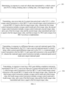
- FIG. 2 is a flowchart of a method for controlling gear shifting of a hybrid electric vehicle according to some embodiments of the present disclosure. Referring to FIG. 2 , the method is applied to the transmission control unit (TCU) 1. The method includes the following steps.
- the TCU 1 receives a vehicle state transmitted from the VCU 2 as the braking state or the sliding state, it indicates that a downshift operation is required for the TM that is operating in this case, and the first target torque value needs to be determined to meet the torque required at the wheel ends of the vehicle during gear shifting.
- the TCU 1 needs to transmit, once at an interval of the preset time period, the first torque control instruction to the first MCU 31 of the ISG via the VCU 2 to gradually increase the torque of the ISG 3, and the second torque control instruction to the second MCU 41 of the TM via the VCU 2 to gradually decrease the torque of the TM 4.
- the ISG 3 can gradually replace the TM 4 to provide the negative torque for the wheels, and the continuity of the negative torque applied to the wheel ends of the vehicle is maintained, such that the vehicle can run smoothly.
- FIG. 4 is a schematic diagram of time-dependent changes of a pressed state of a clutch and a control mode of an ISG in a method for controlling gear shifting of a hybrid electric vehicle according to some embodiments of the present disclosure.
- the pressure applied to the clutch 5 is gradually increased.
- the preset speed difference range is 200 rmp to 400 rmp.
- the TCU 1 needs to control the torque of the clutch 5 while controlling the ISG 3 and the TM 4. Therefore, the second pressure instruction is transmitted to the clutch 5 via the VCU 2, such that the pressure value applied to the clutch 5 is kept at the second pressure value, and a speed difference existing between the rotational speed of the ISG and the rotational speed of the clutch 5 can be ensured.
- the ISG 3 in order from left to right, within a time period between the first vertical dotted line and a second vertical dotted line, the ISG 3 is in the rotational speed control mode, and the pressure applied to the clutch 5 is kept at the second pressure value.
- the method for controlling gear shifting of the hybrid electric vehicle further includes the following steps: In a first step, in the case that the difference between the received rotational speed of the ISG 3 that is transmitted by the VCU 2 and the received rotational speed of the clutch 5 being within the preset speed difference range, in response to the received vehicle state transmitted by the VCU 2 being an acceleration state, a second target torque value is determined.
- the TCU 1 receives the vehicle state transmitted by the VCU 2 as the acceleration state, indicating that the driver has an acceleration request in the gear shifting process, and the second target torque value needs to be re-determined.
- a fifth torque control instruction is transmitted to the first MCU 31 and the second pressure instruction is transmitted to the clutch 5 once at an interval of the preset time period via the VCU 2 based on the second target torque value, wherein the fifth torque control instruction includes a torque control mode and a fifth torque value, and along with an increase of a quantity of transmitting times, a value of the fifth torque value is first decreased and then increased.
- the TCU1 receives a state of an accelerator as a pressed state, that is, the driver presses the accelerator to accelerate
- the ISG 3 is no longer suitable for control by using the rotational speed control mode, and needs to be switched to the torque control mode again for control. Therefore, the TCU 1 transmits the fifth torque control instruction to the first MCU 31 via the VCU 2, such that the ISG is switched from the rotational speed control mode to the torque control mode, and the vehicle is driven to run by converting the negative torque into a positive torque.
- the TCU 1 also needs to transmit the second pressure instruction to the clutch 5 via the VCU 2, such that the clutch 5 is pressed to be closed to complete a synchronization action quickly.
- a fourth pressure instruction is transmitted to the clutch 5 once at an interval of the preset time period, wherein the fourth pressure instruction includes a fourth pressure value, a fourth pressure value in a current fourth pressure instruction being less than a fourth pressure value in a previous fourth pressure instruction.
- the pressure value applied to the clutch 5 is gradually decreased, such that the rotational speed of the ISG is synchronized with the rotational speed of the clutch 5.
- step 204 in response to receiving a TM 4 gear-shifting completion instruction transmitted by the VCU 2, a third torque control instruction is transmitted to the first MCU 31 and a fourth torque control instruction is transmitted to the second MCU 41 once at an interval of the preset time period via the VCU 2 based on the first target torque value, wherein the third torque control instruction includes a torque control mode and a third torque value, the fourth torque control instruction includes a torque control mode and a fourth torque value, and a sum of the third torque value and the fourth torque value transmitted each time is equal to the first target torque value.
- the TM 4 replaces the ISG 3, and provides the negative torque for the wheels again.
- the TCU 1 needs to transmit, once at an interval of the preset time period, the third torque control instruction to the first MCU 31 via the VCU 2 to gradually decrease the torque of the ISG 3, and the fourth torque control instruction to the second MCU 41 via the VCU 2 to control to gradually increase the torque of the TM 4.
- the TM 4 can gradually replace the ISG 3 to provide the negative torque for the wheels, and the continuity of the negative torque applied to the wheel ends of the vehicle is maintained, such that the vehicle can run smoothly.
- a difference between third torque values contained in two adjacent third torque control instructions transmitted to the first MCU 31 via the VCU 2 is the same as a difference between fourth torque values contained in corresponding fourth torque control instructions transmitted to the second MCU 41. That is, an amount of decrease in the torque value of the ISG 3 is the same as an amount of increase in the torque value of the TM 4.
- transmitting, via the VCU 2, the third torque control instruction to the first MCU 31 and the fourth torque control instruction to the second MCU 41 includes transmitting 0 as the third torque value in the third torque control instruction transmitted to the first MCU 31 via the VCU 2, and transmitting the first target torque value as the fourth torque value in the fourth torque control instruction transmitted to the second MCU 41 via the VCU 2.
- the TM 4 can completely replace the ISG 3 to provide the negative torque for the wheels, that is, the gear shifting operation of the TM 4 is completed.
- the torque value of the TM 4 is gradually increased, the torque value of the ISG 3 is gradually decreased, and the amount of decrease in the torque value of the TM 4 is the same as the amount of increase in the torque value of the ISG 3.
- a third pressure instruction is transmitted to the clutch 5 via the VCU 2 while the third torque control instruction is transmitted to the first MCU 31 and the fourth torque control instruction is transmitted to the second MCU 41 via the VCU 2, wherein the third pressure instruction includes a third pressure value, and a third pressure value in a current third pressure instruction is less than a third pressure value in a previous third pressure instruction.
- the TCU 1 also needs to control the torque of the clutch 5 while controlling the ISG 3 and the TM 4. Therefore, the third pressure instruction is transmitted to the clutch 5 while the third torque control instruction is transmitted to the first MCU 31 and the fourth torque control instruction is transmitted to the second MCU 41 once at an interval of the preset time period, such that the pressure applied to the clutch 5 is gradually decreased, so as to decrease the capacity of transmitting the torque until the clutch 5 is separated from the ISG 3.
- the ISG 3 in order from left to right, within a time period between the second vertical dotted line and a third vertical dotted line, the ISG 3 is in the torque control mode, and the pressure applied to the clutch 5 is gradually decreased.
- the TCU 1 is used to control the first MCU 31 of the ISG 3 to cooperate with the second MCU 41 of the TM 4 to replace a torque value, such that during gear shifting of the TM 4, the ISG 3 can timely make up for the torque lost by the TM 4 in the neutral gear taking and gear shifting processes, and the torque of the ISG 3 is transferred to the TM 4 again after the TM 4 completes gear shifting, thereby avoiding a lack of the torque of the TM 4 in the gear shifting process, solving the problem of sudden acceleration that may occur in the vehicle in the gear shifting process, ensuring the smoothness of traveling, and optimizing the driving and riding experience of the occupants.
- the embodiments of the present disclosure further provide an apparatus for controlling gear shifting of a hybrid electric vehicle.
- the apparatus may be arranged in a transmission control unit (TCU). As shown in FIG. 5 , the apparatus includes:
- a difference between first torque values contained in two adjacent first torque control instructions transmitted to the first MCU via the VCU is the same as a difference between second torque values contained in corresponding second torque control instructions transmitted to the second MCU.
- the apparatus further includes:
- the apparatus further includes an eighth instruction transmitting module, configured to transmit, via the VCU, a third pressure instruction to the clutch while transmitting, via the VCU, the third torque control instruction to the first MCU and the fourth torque control instruction to the second MCU, wherein the third pressure instruction includes a third pressure value, a third pressure value in a current third pressure instruction being less than a third pressure value in a previous third pressure instruction.
- an eighth instruction transmitting module configured to transmit, via the VCU, a third pressure instruction to the clutch while transmitting, via the VCU, the third torque control instruction to the first MCU and the fourth torque control instruction to the second MCU, wherein the third pressure instruction includes a third pressure value, a third pressure value in a current third pressure instruction being less than a third pressure value in a previous third pressure instruction.
- the preset speed difference range is 200 rmp to 400 rmp.
- the present disclosure further provides a computer program product including at least one computer program or at least one computer instruction.
- the at least one computer program or at least one computer instruction when executed by a processor, causes the processor to perform the method for controlling gear shifting of the hybrid electric vehicle as defined in the above-described method embodiments.
Landscapes
- Engineering & Computer Science (AREA)
- Transportation (AREA)
- Mechanical Engineering (AREA)
- Chemical & Material Sciences (AREA)
- Combustion & Propulsion (AREA)
- Automation & Control Theory (AREA)
- Electric Propulsion And Braking For Vehicles (AREA)
- Control Of Transmission Device (AREA)
Abstract
Description
- The present disclosure claims priority to
Chinese Patent Application No. 202211230507.7, filed on October 08, 2022 - The present disclosure relates to the field of vehicle electric control technology, and in particular, relates to a method and apparatus for controlling gear shifting of a hybrid electric vehicle, and a storage medium.
- With a series of social problems brought by the continuous increase in vehicle ownership, the depletion of fossil energy, and the deterioration of the atmospheric environment, the state has successively issued policies to encourage and require the development of new energy vehicles. However, pure electric new energy vehicles are affected by subjective and objective factors such as inconvenient charging and short range, which bring poor practical experience to users. Hybrid electric vehicles, which are also in the field of new energy vehicles, have gradually gained popularity in the market due to their superior energy saving and emission reduction as well as better user experience.
- In view of the above, the present disclosure provides a method and apparatus for controlling gear shifting of a hybrid electric vehicle, and a storage medium.
- Specifically, the present disclosure includes the following technical solution.
- In a first aspect, embodiments of the present disclosure provide a method for controlling gear shifting of a hybrid electric vehicle. The method is applied to a transmission control unit (TCU) connected to a vehicle control unit (VCU), wherein the VCU is connected to a first microcontroller unit (MCU) of an integrated starter generator (ISG), a second MCU of a traction motor (TM), and a clutch, and the method includes:
- determining, in response to a received vehicle state transmitted by the VCU being a braking state or a sliding state, a first target torque value;
- transmitting, once at an interval of a preset time period and via the VCU, a first torque control instruction to the first MCU and a second torque control instruction to the second MCU based on the first target torque value, wherein the first torque control instruction includes a torque control mode and a first torque value, the second torque control instruction includes a torque control mode and a second torque value, and a sum of the first torque value and the second torque value transmitted each time is equal to the first target torque value;
- transmitting, in response to a difference between a received rotational speed of the ISG that is transmitted by the VCU and a received rotational speed of the clutch being within a preset speed difference range and via the VCU, a rotational speed control instruction to the first MCU and a gear shift instruction to the second MCU, wherein the rotational speed control instruction includes a rotational speed control mode and a target rotational speed; and
- transmitting, in response to receiving a TM gear-shifting completion instruction transmitted by the VCU, once at an interval of a preset time period and via the VCU, a third torque control instruction to the first MCU and a fourth torque control instruction to the second MCU based on the first target torque value, wherein the third torque control instruction includes a torque control mode and a third torque value, the fourth torque control instruction includes a torque control mode and a fourth torque value, and a sum of the third torque value and the fourth torque value transmitted each time is equal to the first target torque value.
- In some embodiments, a difference between first torque values contained in two adjacent first torque control instructions transmitted to the first MCU via the VCU is the same as a difference between second torque values contained in corresponding second torque control instructions transmitted to the second MCU.
- In some embodiments, transmitting, via the VCU, the first torque control instruction to the first MCU and the second torque control instruction to the second MCU, includes:
transmitting the first target torque value as the first torque value in the first torque control instruction transmitted to the first MCU via the VCU, and transmitting 0 as the second torque value in the second torque control instruction transmitted to the second MCU via the VCU. - In some embodiments, transmitting, via the VCU, the third torque control instruction to the first MCU and the fourth torque control instruction to the second MCU, includes:
transmitting 0 as the third torque value in the third torque control instruction transmitted to the first MCU via the VCU, and transmitting the first target torque value as the fourth torque value in the fourth torque control instruction transmitted to the second MCU via the VCU. - In some embodiments, the method further includes:
transmitting, via the VCU, a first pressure instruction to the clutch while transmitting, via the VCU, the first torque control instruction to the first MCU and the second torque control instruction to the second MCU, wherein the first pressure instruction includes a first pressure value, a first pressure value in a current first pressure instruction being greater than a first pressure value in a previous first pressure instruction. - In some embodiments, the method further includes:
transmitting, via the VCU, a second pressure instruction to the clutch while transmitting, via the VCU, the rotational speed control instruction to the first MCU and the gear shift instruction to the second MCU, wherein the second pressure instruction includes a second pressure value. - In some embodiments, the method further includes:
- determining a second target torque value in the case that the difference between the received rotational speed of the ISG that is transmitted by the VCU and the received rotational speed of the clutch being within the preset speed difference range and in response to the received vehicle state transmitted by the VCU being an acceleration state;
- transmitting, once at an interval of the preset time period and via the VCU, a fifth torque control instruction to the first MCU and the second pressure instruction to the clutch based on the second target torque value, wherein the fifth torque control instruction includes a torque control mode and a fifth torque value, and along with an increase of a quantity of transmitting times, a value of the fifth torque value is first decreased and then increased; and
- transmitting, in response to a received torque value of the ISG that is transmitted by the VCU being the second target torque value, once at an interval of the preset time period, a fourth pressure instruction to the clutch, wherein the fourth pressure instruction includes a fourth pressure value, a fourth pressure value in a current fourth pressure instruction being less than a fourth pressure value in a previous fourth pressure instruction.
- In some embodiments, the method further includes:
transmitting, via the VCU, a third pressure instruction to the clutch while transmitting, via the VCU, the third torque control instruction to the first MCU and the fourth torque control instruction to the second MCU, wherein the third pressure instruction includes a third pressure value, a third pressure value in a current third pressure instruction being less than a third pressure value in a previous third pressure instruction. - In some embodiments, the rotational speed control mode is implemented by proportional-integral-derivative (PID) control.
- In some embodiments, the preset speed difference range is 200 rmp to 400 rmp.
- In a second aspect, embodiments of the present disclosure further provide an apparatus for controlling gear shifting of a hybrid electric vehicle. The apparatus includes:
- a first torque value determining module, configured to determine, in response to a received vehicle state transmitted by a vehicle control unit (VCU) being a braking state or a sliding state, a first target torque value;
- a first instruction transmitting module, configured to transmit, once at an interval of a preset time period and via the VCU, a first torque control instruction to a first microcontroller unit (MCU) and a second torque control instruction to a second MCU based on the first target torque value, wherein the first torque control instruction includes a torque control mode and a first torque value, the second torque control instruction includes a torque control mode and a second torque value, and a sum of the first torque value and the second torque value transmitted each time is equal to the first target torque value;
- a second instruction transmitting module, configured to transmit, in response to a difference between a received rotational speed of an integrated starter generator (ISG) that is transmitted by the VCU and a received rotational speed of a clutch being within a preset speed difference range and via the VCU, a rotational speed control instruction to the first MCU and a gear shift instruction to the second MCU, wherein the rotational speed control instruction includes a rotational speed control mode and a target rotational speed; and
- a third instruction transmitting module, configured to transmit, in response to receiving a traction motor (TM) gear-shifting completion instruction transmitted by the VCU, once at an interval of the preset time period and via the VCU, a third torque control instruction to the first MCU and a fourth torque control instruction to the second MCU based on the first target torque value, wherein the third torque control instruction includes a torque control mode and a third torque value, the fourth torque control instruction includes a torque control mode and a fourth torque value, and a sum of the third torque value and the fourth torque value transmitted each time is equal to the first target torque value.
- In some embodiments, a difference between first torque values contained in two adjacent first torque control instructions transmitted to the first MCU via the VCU is the same as a difference between second torque values contained in corresponding second torque control instructions transmitted to the second MCU.
- In some embodiments, the first instruction transmitting module is specifically configured to:
transmit the first target torque value as the first torque value in the first torque control instruction transmitted to the first MCU via the VCU, and transmit 0 as the second torque value in the second torque control instruction transmitted to the second MCU via the VCU. - In some embodiments, the third instruction transmitting module is specifically configured to:
transmit 0 as the third torque value in the third torque control instruction transmitted to the first MCU via the VCU, and transmit the first target torque value as the fourth torque value in the fourth torque control instruction transmitted to the second MCU via the VCU. - In some embodiments, the apparatus further includes:
a forth instruction transmitting module, configured to transmit, via the VCU, a first pressure instruction to the clutch while transmitting, via the VCU, the first torque control instruction to the first MCU and the second torque control instruction to the second MCU, wherein the first pressure instruction includes a first pressure value, a first pressure value in a current first pressure instruction being greater than a first pressure value in a previous first pressure instruction. - In some embodiments, the apparatus further includes:
a fifth instruction transmitting module, configured to transmit, via the VCU, a second pressure instruction to the clutch while transmitting, via the VCU, the rotational speed control instruction to the first MCU and the gear shift instruction to the second MCU, wherein the second pressure instruction includes a second pressure value. - In some embodiments, the apparatus further includes:
- a second torque value determining module, configured to determine a second target torque value in the case that the difference between the received rotational speed of the ISG that is transmitted by the VCU and the received rotational speed of the clutch being within the preset speed difference range and in response to the received vehicle state transmitted by the VCU being an acceleration state;
- a sixth instruction transmitting module, configured to transmit, once at an interval of the preset time period and via the VCU, a fifth torque control instruction to the first MCU and the second pressure instruction to the clutch based on the second target torque value, wherein the fifth torque control instruction includes a torque control mode and a fifth torque value, and along with an increase of a quantity of transmitting times, a value of the fifth torque value is first decreased and then increased; and
- a seventh instruction transmitting module, configured to transmit, in response to a received torque value of the ISG that is transmitted by the VCU being the second target torque value, once at an interval of the preset time period, a fourth pressure instruction to the clutch, wherein the fourth pressure instruction includes a fourth pressure value, a fourth pressure value in a current fourth pressure instruction being less than a fourth pressure value in a previous fourth pressure instruction.
- In some embodiments, the apparatus further includes:
an eighth instruction transmitting module, configured to transmit, via the VCU, a third pressure instruction to the clutch while transmitting, via the VCU, the third torque control instruction to the first MCU and the fourth torque control instruction to the second MCU, wherein the third pressure instruction includes a third pressure value, a third pressure value in a current third pressure instruction being less than a third pressure value in a previous third pressure instruction. - In some embodiments, the rotational speed control mode is implemented by proportional-integral-derivative (PID) control.
- In some embodiments, the preset speed difference range is 200 rmp to 400 rmp.
- In a third aspect, embodiments of the present disclosure further provide a non-transitory computer-readable storage medium storing at least one computer instruction. The at least one computer instruction, when loaded and executed by a processor, causes the processor to perform the method for controlling gear shifting of the hybrid electric vehicle as defined in the above first aspect.
- For describing the technical solutions in the embodiments of the present disclosure more clearly, the following briefly describes the accompanying drawings required for describing the embodiments. Apparently, the accompanying drawings in the following description show merely some embodiments of the present disclosure, and those of ordinary skill in the art may still derive other drawings from these accompanying drawings without creative efforts.
-
FIG. 1 is a scene schematic diagram of a method for controlling gear shifting of a hybrid electric vehicle according to some embodiments of the present disclosure; -
FIG. 2 is a flowchart of a method for controlling gear shifting of a hybrid electric vehicle according to some embodiments of the present disclosure; -
FIG. 3 is a schematic diagram of time-dependent changes of a torque of an ISG and a torque of a TM in a method for controlling gear shifting of a hybrid electric vehicle according to some embodiments of the present disclosure; -
FIG. 4 is a schematic diagram of time-dependent changes of a pressed state of a clutch and a control mode of an ISG in a method for controlling gear shifting of a hybrid electric vehicle according to some embodiments of the present disclosure; and -
FIG. 5 is a schematic structural diagram of an apparatus for controlling gear shifting of a hybrid electric vehicle according to some embodiments of the present disclosure. - The reference numerals in the drawings are respectively denoted as:
1-Transmission control unit TCU; 2-Vehicle control unit VCU; 3-integrated starter generator ISG, 31-First microcontroller unit MCU; 4-traction motor TM, 41- second microcontroller unit MCU; and 5-Clutch. - The technical solutions in embodiments of the present disclosure will be described hereinafter with reference to the accompanying drawings in the embodiments of the present disclosure, and it is apparent that the described embodiments are only a part, but not all of the embodiments of the present disclosure. All other embodiments obtained by those of ordinary skill in the art without creative efforts with respect to the embodiments in the present disclosure shall fall within the protection scope of the present disclosure.
- Unless otherwise defined, all technical terms used in the embodiments of the present disclosure have the same meaning as commonly understood by those of ordinary skills in the art. Some technical terms appearing in the embodiments of the present disclosure are explained hereinafter.
-
FIG. 1 is a scene schematic diagram of a method for controlling gear shifting of a hybrid electric vehicle according to some embodiments of the present disclosure. Referring toFIG. 1 , a transmission control unit (TCU) 1, a vehicle control unit (VCU) 2, an integrated starter generator (ISG) 3, a traction motor (TM) 4, and a clutch 5 are included. - The
ISG 3 includes a first microcontroller unit (MCU) 31, and theTM 4 includes asecond MCU 41. TheTCU 1 is connected to theVCU 2, and theVCU 2 is connected to thefirst MCU 31, thesecond MCU 41, and theclutch 5, respectively. - In some embodiments, the
TCU 1 is configured to receive information transmitted from theVCU 2, and transmit the information to theVCU 2 after performing corresponding processing. TheVCU 2 is used for being connected to various components on the vehicle, such as theISG 3, theTM 4 and theclutch 5, and can control the various components to perform corresponding actions. TheISG 3 and the TM are configured to convert electrical energy into mechanical energy when in an operating state, convert mechanical energy into electrical energy when in a power generation mode, and neither convert electrical energy into mechanical energy nor convert mechanical energy into electrical energy when in an inoperative state. Theclutch 5 is configured to cooperate with the TM and the ISG to realize the transmission of a torque. - Currently, during deceleration braking of the hybrid electric vehicle, the TM provides a negative torque for wheels to decelerate the vehicle. However, TM gear shifting is synchronizer gear shifting, requiring to pass through a neutral position. In the neutral position, the TM is temporarily unable to provide the negative torque for the wheels. The transient loss of the torque easily causes a sudden acceleration of the hybrid electric vehicle in the gear shifting process, affecting the smoothness of traveling.
-
FIG. 2 is a flowchart of a method for controlling gear shifting of a hybrid electric vehicle according to some embodiments of the present disclosure. Referring toFIG. 2 , the method is applied to the transmission control unit (TCU) 1. The method includes the following steps. - In
step 201, in response to a received vehicle state transmitted by a vehicle control unit (VCU) 2 being a braking state or a sliding state, a first target torque value is determined. - In the case that the
TCU 1 receives a vehicle state transmitted from theVCU 2 as the braking state or the sliding state, it indicates that a downshift operation is required for the TM that is operating in this case, and the first target torque value needs to be determined to meet the torque required at the wheel ends of the vehicle during gear shifting. - In
step 202, a first torque control instruction is transmitted to thefirst MCU 31 and a second torque control instruction is transmitted to thesecond MCU 41 once at an interval of a preset time period via theVCU 2 based on the first target torque value, wherein the first torque control instruction includes a torque control mode and a first torque value, the second torque control instruction includes a torque control mode and a second torque value, and a sum of the first torque value and the second torque value transmitted each time is equal to the first target torque value, such that a torque of theTM 4 and a torque of theISG 3 are always complementary. - In the case that the torque of the motor changes too quickly when the vehicle needs gear shifting during driving, it is easily lead to unstable driving, affecting the driving and riding experience of the occupants is affected. Therefore, in the case that the vehicle state is determined as the braking state or the sliding state, the
TCU 1 needs to transmit, once at an interval of the preset time period, the first torque control instruction to thefirst MCU 31 of the ISG via theVCU 2 to gradually increase the torque of theISG 3, and the second torque control instruction to thesecond MCU 41 of the TM via theVCU 2 to gradually decrease the torque of theTM 4. In this stage, theISG 3 can gradually replace theTM 4 to provide the negative torque for the wheels, and the continuity of the negative torque applied to the wheel ends of the vehicle is maintained, such that the vehicle can run smoothly. - It should be noted that, control modes are preset in the
first MCU 31 and thesecond MCU 41, and in the case that theTCU 1 transmits the instructions to thefirst MCU 31 and thesecond MCU 41, the instructions need to include control information to determine the control modes of the ISG and the TM. - In some embodiments, the control modes include a torque control mode and a rotational speed control mode.
- It should be noted that, in the case that the
ISG 3 or theTM 4 works in the torque control mode, thefirst MCU 31 or thesecond MCU 41 may acquire a difference between a target rotational speed and the current rotational speed of theISG 3 or theTM 4, a corresponding required current value is determined based on "voltage-speed-current" MAP data, and the current value is output to a stator of theISG 3 or theTM 4 via a current control module IGBT, so as to achieve the required torque. - In some embodiments, in order to ensure that the torque of the TM and the torque of the ISG change in the same way, a difference between first torque values contained in two adjacent first torque control instructions transmitted to the
first MCU 31 via theVCU 2 is the same as a difference between second torque values contained in corresponding second torque control instructions transmitted to thesecond MCU 41. That is, an amount of increase in the torque value of theISG 3 is the same as an amount of decrease in the torque value of theTM 4. - Exemplarily,
FIG. 3 is a schematic diagram of time-dependent changes of a torque of an ISG and a torque of a TM in a method for controlling gear shifting of a hybrid electric vehicle according to some embodiments of the present disclosure. Referring toFIG. 3 , in order from left to right, within a time period before a first vertical dotted line, in a negative direction, the torque value of theTM 4 is gradually decreased, the torque value of theISG 3 is gradually increased, and the amount of decrease in the torque value of theTM 4 is the same as the amount of increase in the torque value of theISG 3. - In some embodiments, transmitting, via the
VCU 2, the first torque control instruction to thefirst MCU 31 and the second torque control instruction to thesecond MCU 41, includes transmitting the first target torque value as the first torque value in the first torque control instruction transmitted to thefirst MCU 31 via theVCU 2, and transmitting 0 as the second torque value in the second torque control instruction transmitted to thesecond MCU 41 via the VCU. In this case, theISG 3 can completely replace theTM 4 to provide the negative torque for the wheels, such that theTM 4 can be conveniently and subsequently shifted to neutral gear and speed regulation and gear shifting. - Exemplarily, referring to
FIG. 3 , in order from left to right, at a time corresponding to the first vertical dotted line, the torque value of the ISG is the first target torque value, and the torque value of the TM is 0. - In some embodiments, a first pressure instruction is transmitted to the
clutch 5 via theVCU 2 while the first torque control instruction is transmitted to thefirst MCU 31 via theVCU 2 and the second torque control instruction is transmitted to thesecond MCU 41 via theVCU 2. The first pressure instruction includes a first pressure value, a first pressure value in a current first pressure instruction being greater than a first pressure value in a previous first pressure instruction. - The
TCU 1 also needs to control the torque of the clutch 5 while controlling theISG 3 and theTM 4. Therefore, the first pressure instruction is transmitted to the clutch 5 while the first torque control instruction is transmitted to thefirst MCU 31 and the second torque control instruction is transmitted to thesecond MCU 41 once at an interval of a preset time period, such that the pressure applied to theclutch 5 is gradually increased, so as to increase the capacity of transmitting the torque. - Exemplarily,
FIG. 4 is a schematic diagram of time-dependent changes of a pressed state of a clutch and a control mode of an ISG in a method for controlling gear shifting of a hybrid electric vehicle according to some embodiments of the present disclosure. Referring toFIG. 4 , in order from left to right, within a time period before a first vertical dotted line, in the case that theISG 3 is in the torque control mode, the pressure applied to theclutch 5 is gradually increased. - In
step 203, in response to a difference between a received rotational speed of theISG 3 that is transmitted by theVCU 2 and a received rotational speed of a clutch 5 being within a preset speed difference range, a rotational speed control instruction is transmitted to thefirst MCU 31 via theVCU 2 and a gear shift instruction is transmitted to thesecond MCU 41 via theVCU 2, wherein the rotational speed control instruction includes a rotational speed control mode and a target rotational speed. - In the case that the speed difference exists between the rotational speed of the
ISG 3 and the rotational speed of theclutch 5 and the speed difference is within the preset speed difference range, the torque control mode is not suitable for the ISG that is operating in this case, and the ISG alone needs to provide the negative torque, such that theTCU 1 needs to change the control mode of theISG 3 via theVCU 2 and control the TM to perform neutral gear taking and gear shifting operations. At this stage, the negative torque carried by the TM is completely transferred to the ISG, and the TM can be shifted to neutral gear and then perform speed regulation and gear shifting. - It should be noted that the speed difference between the rotational speed of the
ISG 3 and the rotational speed of the clutch 5 is within the preset speed difference range, such that theISG 3 can still provide a corresponding negative torque in the rotational speed control mode, and is kept in a slipping state with theclutch 5. It should be understood that theclutch 5 is pressed to have a torque transmission capacity under a corresponding pressure, and the required torque transmission capacity is calculated by dividing by a transmission ratio based on the wheel-end torque demand, and theISG 3 needs to output a torque which is relative in magnitude and opposite in direction to the torque of the clutch 5, so as to achieve the purpose of controlling the rotational speed. - In some embodiments, the rotational speed control mode is implemented by proportional-integral-derivative (PID) control.
- It should be noted that the PID control, also referred to as a PID control system, is a control system for controlling the proportional, integral and derivative of an error generated by comparing real-time data collected information of a controlled object with a given value during the industrial process control. The PID control has the advantages of simple principle, strong robustness, wide practical range, and the like. The PID control is linear control in which a controlled object is controlled by linearly combining a proportion (P), an integral (I), and a derivative (D) of a deviation between a given value r(t) and an actual output value y(t) in the form of coefficients.
- In some embodiments, the
first MCU 31 or thesecond MCU 41 acquires a difference value between the target rotational speed and the current rotational speed of theISG 3 or theTM 4, the required torque value of the ISG or theTM 4 is determined by operation of a proportional coefficient, an integral time constant, and a derivative time constant, the corresponding required current value is determined by looking up the "voltage-speed-current" MAP data, then an IGBT module is controlled to output the current value to the stator of theISG 3 or theTM 4 to reach the required torque, an increase in torque of theISG 3 or theTM 4 in the process increases the rotational speed of the motor, and a decrease in torque of theISG 3 or theTM 4 in the process can slow down the increase of the rotational speed of theISG 3 or theTM 4. The required torque can be automatically calculated according to the difference value between the actual rotational speed and the target rotational speed through the regulation of PID, such that the rotational speed control is realized, and the target rotational speed is quickly and stably reached. - Exemplarily, referring to
FIG. 3 , in order from left to right, within a time period between the first vertical dotted line and a second vertical dotted line, in a negative direction, the torque value of theTM 4 is 0, and the torque value of theISG 3 is the target torque value. - In some embodiments, the preset speed difference range is 200 rmp to 400 rmp.
- In the case that the difference between the rotational speeds of the
ISG 3 and theclutch 3 is within the range of 200 rmp to 400 rmp, the smoothness of the vehicle is best. - In some embodiments, a second pressure instruction is transmitted to the
clutch 5 via theVCU 2 while the rotational speed control instruction is transmitted to thefirst MCU 31 via theVCU 2 and the gear shift instruction is transmitted to thesecond MCU 41 via theVCU 2, wherein the second pressure instruction includes a second pressure value. - At this stage, the
TCU 1 needs to control the torque of the clutch 5 while controlling theISG 3 and theTM 4. Therefore, the second pressure instruction is transmitted to theclutch 5 via theVCU 2, such that the pressure value applied to theclutch 5 is kept at the second pressure value, and a speed difference existing between the rotational speed of the ISG and the rotational speed of the clutch 5 can be ensured. - Exemplarily, referring to
FIG. 4 , in order from left to right, within a time period between the first vertical dotted line and a second vertical dotted line, theISG 3 is in the rotational speed control mode, and the pressure applied to theclutch 5 is kept at the second pressure value. - In some embodiments, in the process of implementing the step, in the case that a driver has an acceleration demand in the gear shifting process, the method for controlling gear shifting of the hybrid electric vehicle provided by the embodiments of the present disclosure further includes the following steps:
In a first step, in the case that the difference between the received rotational speed of theISG 3 that is transmitted by theVCU 2 and the received rotational speed of the clutch 5 being within the preset speed difference range, in response to the received vehicle state transmitted by theVCU 2 being an acceleration state, a second target torque value is determined. - The
TCU 1 receives the vehicle state transmitted by theVCU 2 as the acceleration state, indicating that the driver has an acceleration request in the gear shifting process, and the second target torque value needs to be re-determined. - It should be understood that in this step, the negative torque carried by the
TM 4 has been completely transferred to theISG 3, and therefore, in this case, the second target torque value is now acting on theISG 3. - In a second step, a fifth torque control instruction is transmitted to the
first MCU 31 and the second pressure instruction is transmitted to the clutch 5 once at an interval of the preset time period via theVCU 2 based on the second target torque value, wherein the fifth torque control instruction includes a torque control mode and a fifth torque value, and along with an increase of a quantity of transmitting times, a value of the fifth torque value is first decreased and then increased. - In the case that the TCU1 receives a state of an accelerator as a pressed state, that is, the driver presses the accelerator to accelerate, in this case, the
ISG 3 is no longer suitable for control by using the rotational speed control mode, and needs to be switched to the torque control mode again for control. Therefore, theTCU 1 transmits the fifth torque control instruction to thefirst MCU 31 via theVCU 2, such that the ISG is switched from the rotational speed control mode to the torque control mode, and the vehicle is driven to run by converting the negative torque into a positive torque. Meanwhile, in order to achieve cooperation with theISG 3, theTCU 1 also needs to transmit the second pressure instruction to theclutch 5 via theVCU 2, such that theclutch 5 is pressed to be closed to complete a synchronization action quickly. - In a third step, in response to a received torque value of the
ISG 3 that is transmitted by theVCU 2 being the second target torque value, a fourth pressure instruction is transmitted to the clutch 5 once at an interval of the preset time period, wherein the fourth pressure instruction includes a fourth pressure value, a fourth pressure value in a current fourth pressure instruction being less than a fourth pressure value in a previous fourth pressure instruction. - In the case that the torque value of the
ISG 3 is the second target torque value, the pressure value applied to theclutch 5 is gradually decreased, such that the rotational speed of the ISG is synchronized with the rotational speed of theclutch 5. - In
step 204, in response to receiving aTM 4 gear-shifting completion instruction transmitted by theVCU 2, a third torque control instruction is transmitted to thefirst MCU 31 and a fourth torque control instruction is transmitted to thesecond MCU 41 once at an interval of the preset time period via theVCU 2 based on the first target torque value, wherein the third torque control instruction includes a torque control mode and a third torque value, the fourth torque control instruction includes a torque control mode and a fourth torque value, and a sum of the third torque value and the fourth torque value transmitted each time is equal to the first target torque value. - After the
TM 4 has completed gear shifting, theTM 4 replaces theISG 3, and provides the negative torque for the wheels again. In this case, theTCU 1 needs to transmit, once at an interval of the preset time period, the third torque control instruction to thefirst MCU 31 via theVCU 2 to gradually decrease the torque of theISG 3, and the fourth torque control instruction to thesecond MCU 41 via theVCU 2 to control to gradually increase the torque of theTM 4. In this stage, theTM 4 can gradually replace theISG 3 to provide the negative torque for the wheels, and the continuity of the negative torque applied to the wheel ends of the vehicle is maintained, such that the vehicle can run smoothly. - In some embodiments, in order to ensure that the torque of the TM and the torque of the ISG change in the same way, a difference between third torque values contained in two adjacent third torque control instructions transmitted to the
first MCU 31 via theVCU 2 is the same as a difference between fourth torque values contained in corresponding fourth torque control instructions transmitted to thesecond MCU 41. That is, an amount of decrease in the torque value of theISG 3 is the same as an amount of increase in the torque value of theTM 4. - In some embodiments, transmitting, via the
VCU 2, the third torque control instruction to thefirst MCU 31 and the fourth torque control instruction to thesecond MCU 41, includes transmitting 0 as the third torque value in the third torque control instruction transmitted to thefirst MCU 31 via theVCU 2, and transmitting the first target torque value as the fourth torque value in the fourth torque control instruction transmitted to thesecond MCU 41 via theVCU 2. In this case, theTM 4 can completely replace theISG 3 to provide the negative torque for the wheels, that is, the gear shifting operation of theTM 4 is completed. - Exemplarily, referring to
FIG. 3 , in order from left to right, within a time period between the second vertical dotted line and a third vertical dotted line, in a negative direction, the torque value of theTM 4 is gradually increased, the torque value of theISG 3 is gradually decreased, and the amount of decrease in the torque value of theTM 4 is the same as the amount of increase in the torque value of theISG 3. - In some embodiments, a third pressure instruction is transmitted to the
clutch 5 via theVCU 2 while the third torque control instruction is transmitted to thefirst MCU 31 and the fourth torque control instruction is transmitted to thesecond MCU 41 via theVCU 2, wherein the third pressure instruction includes a third pressure value, and a third pressure value in a current third pressure instruction is less than a third pressure value in a previous third pressure instruction. - In this stage, the
TCU 1 also needs to control the torque of the clutch 5 while controlling theISG 3 and theTM 4. Therefore, the third pressure instruction is transmitted to the clutch 5 while the third torque control instruction is transmitted to thefirst MCU 31 and the fourth torque control instruction is transmitted to thesecond MCU 41 once at an interval of the preset time period, such that the pressure applied to theclutch 5 is gradually decreased, so as to decrease the capacity of transmitting the torque until theclutch 5 is separated from theISG 3. - Exemplarily, referring to
FIG. 4 , in order from left to right, within a time period between the second vertical dotted line and a third vertical dotted line, theISG 3 is in the torque control mode, and the pressure applied to theclutch 5 is gradually decreased. - Therefore, according to the method for controlling gear shifting of the hybrid electric vehicle provided by the embodiments of the present disclosure, in the case that the hybrid electric vehicle is in the braking state or the sliding state, the
TCU 1 is used to control thefirst MCU 31 of theISG 3 to cooperate with thesecond MCU 41 of theTM 4 to replace a torque value, such that during gear shifting of theTM 4, theISG 3 can timely make up for the torque lost by theTM 4 in the neutral gear taking and gear shifting processes, and the torque of theISG 3 is transferred to theTM 4 again after theTM 4 completes gear shifting, thereby avoiding a lack of the torque of theTM 4 in the gear shifting process, solving the problem of sudden acceleration that may occur in the vehicle in the gear shifting process, ensuring the smoothness of traveling, and optimizing the driving and riding experience of the occupants. - The embodiments of the present disclosure further provide an apparatus for controlling gear shifting of a hybrid electric vehicle. The apparatus may be arranged in a transmission control unit (TCU). As shown in
FIG. 5 , the apparatus includes: - a first torque
value determining module 501, configured to determine, in response to a received vehicle state transmitted by a vehicle control unit (VCU) being a braking state or a sliding state, a first target torque value; - a first
instruction transmitting module 502, configured to transmit, once at an interval of a preset time period and via the VCU, a first torque control instruction to a first microcontroller unit (MCU) and a second torque control instruction to a second MCU based on the first target torque value, wherein the first torque control instruction includes a torque control mode and a first torque value, the second torque control instruction includes a torque control mode and a second torque value, and a sum of the first torque value and the second torque value transmitted each time is equal to the first target torque value; - a second
instruction transmitting module 503, configured to transmit, in response to a difference between a received rotational speed of an integrated starter generator (ISG) that is transmitted by the VCU and a received rotational speed of a clutch being within a preset speed difference range and via the VCU, a rotational speed control instruction to the first MCU and a gear shift instruction to the second MCU, wherein the rotational speed control instruction includes a rotational speed control mode and a target rotational speed; and - a third
instruction transmitting module 504, configured to transmit, in response to receiving a traction motor (TM) gear-shifting completion instruction transmitted by the VCU, once at an interval of the preset time period and via the VCU, a third torque control instruction to the first MCU and a fourth torque control instruction to the second MCU based on the first target torque value, wherein the third torque control instruction includes a torque control mode and a third torque value, the fourth torque control instruction includes a torque control mode and a fourth torque value, and a sum of the third torque value and the fourth torque value transmitted each time is equal to the first target torque value. - In some embodiments, a difference between first torque values contained in two adjacent first torque control instructions transmitted to the first MCU via the VCU is the same as a difference between second torque values contained in corresponding second torque control instructions transmitted to the second MCU.
- In some embodiments, the first
instruction transmitting module 502 is specifically configured to transmit the first target torque value as the first torque value in the first torque control instruction transmitted to the first MCU via the VCU, and transmit 0 as the second torque value in the second torque control instruction transmitted to the second MCU via the VCU. - In some embodiments, the third
instruction transmitting module 504 is specifically configured to transmit 0 as the third torque value in the third torque control instruction transmitted to the first MCU via the VCU, and transmit the first target torque value as the fourth torque value in the fourth torque control instruction transmitted to the second MCU via the VCU. - In some embodiments, the apparatus further includes a forth instruction transmitting module, configured to transmit, via the VCU, a first pressure instruction to the clutch while transmitting, via the VCU, the first torque control instruction to the first MCU and the second torque control instruction to the second MCU, wherein the first pressure instruction includes a first pressure value, a first pressure value in a current first pressure instruction being greater than a first pressure value in a previous first pressure instruction.
- In some embodiments, the apparatus further includes a fifth instruction transmitting module, configured to transmit, via the VCU, a second pressure instruction to the clutch while transmitting, via the VCU, the rotational speed control instruction to the first MCU and the gear shift instruction to the second MCU, wherein the second pressure instruction includes a second pressure value.
- In some embodiments, the apparatus further includes:
- a second torque value determining module, configured to determine a second target torque value in the case that the difference between the received rotational speed of the ISG that is transmitted by the VCU and the received rotational speed of the clutch being within the preset speed difference range and in response to the received vehicle state transmitted by the VCU being an acceleration state;
- a sixth instruction transmitting module, configured to transmit, once at an interval of the preset time period and via the VCU, a fifth torque control instruction to the first MCU and the second pressure instruction to the clutch based on the second target torque value, wherein the fifth torque control instruction includes a torque control mode and a fifth torque value, and along with an increase of a quantity of transmitting times, a value of the fifth torque value is first decreased and then increased; and
- a seventh instruction transmitting module, configured to transmit, in response to a received torque value of the ISG that is transmitted by the VCU being the second target torque value, once at an interval of the preset time period, a fourth pressure instruction to the clutch, wherein the fourth pressure instruction includes a fourth pressure value, a fourth pressure value in a current fourth pressure instruction being less than a fourth pressure value in a previous fourth pressure instruction.
- In some embodiments, the apparatus further includes an eighth instruction transmitting module, configured to transmit, via the VCU, a third pressure instruction to the clutch while transmitting, via the VCU, the third torque control instruction to the first MCU and the fourth torque control instruction to the second MCU, wherein the third pressure instruction includes a third pressure value, a third pressure value in a current third pressure instruction being less than a third pressure value in a previous third pressure instruction.
- In some embodiments, the rotational speed control mode is implemented by proportional-integral-derivative (PID) control.
- In some embodiments, the preset speed difference range is 200 rmp to 400 rmp.
- According to the apparatus for controlling gear shifting of the hybrid electric vehicle provided by the embodiments of the present disclosure, in the case that the hybrid electric vehicle is in the braking state or the sliding state, the ISG can timely make up for the torque lost by the TM in the neutral gear taking and gear shifting processes, and the torque of the ISG is transferred to the TM again after the TM completes gear shifting, thereby avoiding a lack of the torque of the TM in the gear shifting process, solving the problem of sudden acceleration that may occur in the vehicle in the gear shifting process, ensuring the smoothness of traveling, and optimizing the driving and riding experience of the occupants.
- The present embodiments and the method embodiments are based on the same inventive concept and the present embodiments are apparatus embodiments corresponding to the method embodiments. Therefore, it should be understood by those skilled in the art that the description of the method embodiments is also applicable to the present embodiments, and some technical details are not described in the present embodiments.
- The embodiments of the present disclosure further provide a vehicle. The vehicle includes the apparatus for controlling gear shifting of the hybrid electric vehicle provided by the previous embodiments.
- Based on the same inventive concept, corresponding to any one of the above-described method embodiments, the present disclosure further provides a non-transitory computer-readable storage medium storing at least one computer instruction. The at least one computer instruction, when loaded and executed by a processor, causes the processor to perform the method for controlling gear shifting of the hybrid electric vehicle as defined in the above-described method embodiments.
- Based on the same inventive concept, corresponding to any one of the above-described method embodiments, the present disclosure further provides a computer program product including at least one computer program or at least one computer instruction. The at least one computer program or at least one computer instruction, when executed by a processor, causes the processor to perform the method for controlling gear shifting of the hybrid electric vehicle as defined in the above-described method embodiments.
- In the present disclosure, the terms "first" and "second" are merely used for descriptive purposes and should not be construed as indicating or implying the relative importance. The term "a plurality of" refers to two or more, unless otherwise explicitly defined.
- Other implementation solutions of the present disclosure are apparent to those skilled in the art from consideration of the specification and practice of the present disclosure disclosed herein. The present disclosure is intended to cover any variations, uses, or adaptations of the present disclosure following the general principles of the present disclosure and including known common knowledge or customary technical means undisclosed in the art of the present disclosure. The specification and embodiments are only considered as exemplary.
- It should be understood that the present disclosure is not limited to the precise arrangements that have been described above and shown in the accompanying drawings, and that various modifications and changes may be made without departing from the scope thereof. The scope of the present disclosure is limited only by the appended claims.
Claims (21)
- A method for controlling gear shifting of a hybrid electric vehicle, being applied to a transmission control unit (TCU) (1) connected to a vehicle control unit (VCU) (2), wherein the VCU (2) is connected to a first microcontroller unit (MCU) (31) of an integrated starter generator (ISG) (3), a second MCU (41) of a traction motor (TM) (4), and a clutch (5), the method comprises:determining, in response to a received vehicle state transmitted by the VCU (2) being a braking state or a sliding state, a first target torque value;transmitting, once at an interval of a preset time period and via the VCU (2), a first torque control instruction to the first MCU (31) and a second torque control instruction to the second MCU (41) based on the first target torque value, wherein the first torque control instruction comprises a torque control mode and a first torque value, the second torque control instruction comprises a torque control mode and a second torque value, and a sum of the first torque value and the second torque value transmitted each time is equal to the first target torque value;transmitting, in response to a difference between a received rotational speed of the ISG (3) that is transmitted by the VCU (2) and a received rotational speed of the clutch (5) being within a preset speed difference range and via the VCU (2), a rotational speed control instruction to the first MCU (31) and a gear shift instruction to the second MCU (41), wherein the rotational speed control instruction comprises a rotational speed control mode and a target rotational speed; andtransmitting, in response to receiving a TM (4) gear-shifting completion instruction transmitted by the VCU (2), once at an interval of a preset time period and via the VCU (2), a third torque control instruction to the first MCU (31) and a fourth torque control instruction to the second MCU (41) based on the first target torque value, wherein the third torque control instruction comprises a torque control mode and a third torque value, the fourth torque control instruction comprises a torque control mode and a fourth torque value, and a sum of the third torque value and the fourth torque value transmitted each time is equal to the first target torque value.
- The method for controlling gear shifting of the hybrid electric vehicle according to claim 1, wherein a difference between first torque values contained in two adjacent first torque control instructions transmitted to the first MCU (31) via the VCU (2) is a same as a difference between second torque values contained in corresponding second torque control instructions transmitted to the second MCU (41).
- The method for controlling gear shifting of the hybrid electric vehicle according to claim 1, wherein said transmitting, via the VCU (2), the first torque control instruction to the first MCU (31) and the second torque control instruction to the second MCU (41) comprises:
transmitting the first target torque value as the first torque value in the first torque control instruction transmitted to the first MCU (31) via the VCU (2), and transmitting 0 as the second torque value in the second torque control instruction transmitted to the second MCU (41) via the VCU (2). - The method for controlling gear shifting of the hybrid electric vehicle according to claim 1, wherein said transmitting, via the VCU (2), the third torque control instruction to the first MCU (31) and the fourth torque control instruction to the second MCU (41) comprises:
transmitting 0 as the third torque value in the third torque control instruction transmitted to the first MCU (31) via the VCU (2), and transmitting the first target torque value as the fourth torque value in the fourth torque control instruction transmitted to the second MCU (41) via the VCU (2). - The method for controlling gear shifting of the hybrid electric vehicle according to claim 1, further comprising:
transmitting, via the VCU (2), a first pressure instruction to the clutch (5) while transmitting, via the VCU (2), the first torque control instruction to the first MCU (31) and the second torque control instruction to the second MCU (41), wherein the first pressure instruction comprises a first pressure value, a first pressure value in a current first pressure instruction being greater than a first pressure value in a previous first pressure instruction. - The method for controlling gear shifting of the hybrid electric vehicle according to claim 1, further comprising:
transmitting, via the VCU (2), a second pressure instruction to the clutch (5) while transmitting, via the VCU (2), the rotational speed control instruction to the first MCU (31) and the gear shift instruction to the second MCU (41), wherein the second pressure instruction comprises a second pressure value. - The method for controlling gear shifting of the hybrid electric vehicle according to claim 6, further comprising:determining a second target torque value in a case that the difference between the received rotational speed of the ISG (3) that is transmitted by the VCU (2) and the received rotational speed of the clutch (5) being within the preset speed difference range and in response to the received vehicle state transmitted by the VCU (2) being an acceleration state;transmitting, once at an interval of the preset time period and via the VCU (2), a fifth torque control instruction to the first MCU (31) and the second pressure instruction to the clutch (5) based on the second target torque value, wherein the fifth torque control instruction comprises a torque control mode and a fifth torque value, and along with an increase of a quantity of transmitting times, a value of the fifth torque value is first decreased and then increased; andtransmitting, in response to a received torque value of the ISG (3) that is transmitted by the VCU (2) being the second target torque value, once at an interval of the preset time period, a fourth pressure instruction to the clutch (5), wherein the fourth pressure instruction comprises a fourth pressure value, a fourth pressure value in a current fourth pressure instruction being less than a fourth pressure value in a previous fourth pressure instruction.
- The method for controlling gear shifting of the hybrid electric vehicle according to claim 1, further comprising:
transmitting, via the VCU (2), a third pressure instruction to the clutch (5) while transmitting, via the VCU (2), the third torque control instruction to the first MCU (31) and the fourth torque control instruction to the second MCU (41), wherein the third pressure instruction comprises a third pressure value, a third pressure value in a current third pressure instruction being less than a third pressure value in a previous third pressure instruction. - The method for controlling gear shifting of the hybrid electric vehicle according to claim 1, wherein the rotational speed control mode is implemented by proportional-integral-derivative (PID) control.
- The method for controlling gear shifting of the hybrid electric vehicle according to claim 1, wherein the preset speed difference range is 200 rmp to 400 rmp.
- An apparatus for controlling gear shifting of a hybrid electric vehicle, comprising:a first torque value determining module, configured to determine, in response to a received vehicle state transmitted by a vehicle control unit (VCU) being a braking state or a sliding state, a first target torque value;a first instruction transmitting module, configured to transmit, once at an interval of a preset time period and via the VCU, a first torque control instruction to a first microcontroller unit (MCU) and a second torque control instruction to a second MCU based on the first target torque value, wherein the first torque control instruction comprises a torque control mode and a first torque value, the second torque control instruction comprises a torque control mode and a second torque value, and a sum of the first torque value and the second torque value transmitted each time is equal to the first target torque value;a second instruction transmitting module, configured to transmit, in response to a difference between a received rotational speed of an integrated starter generator (ISG) that is transmitted by the VCU and a received rotational speed of a clutch being within a preset speed difference range and via the VCU, a rotational speed control instruction to the first MCU and a gear shift instruction to the second MCU, wherein the rotational speed control instruction comprises a rotational speed control mode and a target rotational speed; anda third instruction transmitting module, configured to transmit, in response to receiving a traction motor (TM) gear-shifting completion instruction transmitted by the VCU, once at an interval of the preset time period and via the VCU, a third torque control instruction to the first MCU and a fourth torque control instruction to the second MCU based on the first target torque value, wherein the third torque control instruction comprises a torque control mode and a third torque value, the fourth torque control instruction comprises a torque control mode and a fourth torque value, and a sum of the third torque value and the fourth torque value transmitted each time is equal to the first target torque value.
- The apparatus for controlling gear shifting of the hybrid electric vehicle according to claim 11, wherein a difference between first torque values contained in two adjacent first torque control instructions transmitted to the first MCU via the VCU is a same as a difference between second torque values contained in corresponding second torque control instructions transmitted to the second MCU.
- The apparatus for controlling gear shifting of the hybrid electric vehicle according to claim 11, wherein the first instruction transmitting module is specifically configured to:
transmit the first target torque value as the first torque value in the first torque control instruction transmitted to the first MCU via the VCU, and transmit 0 as the second torque value in the second torque control instruction transmitted to the second MCU via the VCU. - The apparatus for controlling gear shifting of the hybrid electric vehicle according to claim 11, wherein the third instruction transmitting module is specifically configured to:
transmit 0 as the third torque value in the third torque control instruction transmitted to the first MCU via the VCU, and transmit the first target torque value as the fourth torque value in the fourth torque control instruction transmitted to the second MCU via the VCU. - The apparatus for controlling gear shifting of the hybrid electric vehicle according to claim 11, further comprising:
a forth instruction transmitting module, configured to transmit, via the VCU, a first pressure instruction to the clutch while transmitting, via the VCU, the first torque control instruction to the first MCU and the second torque control instruction to the second MCU, wherein the first pressure instruction comprises a first pressure value, a first pressure value in a current first pressure instruction being greater than a first pressure value in a previous first pressure instruction. - The apparatus for controlling gear shifting of the hybrid electric vehicle according to claim 11, further comprising:
a fifth instruction transmitting module, configured to transmit, via the VCU, a second pressure instruction to the clutch while transmitting, via the VCU, the rotational speed control instruction to the first MCU and the gear shift instruction to the second MCU, wherein the second pressure instruction comprises a second pressure value. - The apparatus for controlling gear shifting of the hybrid electric vehicle according to claim 16, further comprising:a second torque value determining module, configured to determine a second target torque value in a case that the difference between the received rotational speed of the ISG that is transmitted by the VCU and the received rotational speed of the clutch being within the preset speed difference range and in response to the received vehicle state transmitted by the VCU being an acceleration state;a sixth instruction transmitting module, configured to transmit, once at an interval of the preset time period and via the VCU, a fifth torque control instruction to the first MCU and the second pressure instruction to the clutch based on the second target torque value, wherein the fifth torque control instruction comprises a torque control mode and a fifth torque value, and along with an increase of a quantity of transmitting times, a value of the fifth torque value is first decreased and then increased; anda seventh instruction transmitting module, configured to transmit, in response to a received torque value of the ISG that is transmitted by the VCU being the second target torque value, once at an interval of the preset time period, a fourth pressure instruction to the clutch, wherein the fourth pressure instruction comprises a fourth pressure value, a fourth pressure value in a current fourth pressure instruction being less than a fourth pressure value in a previous fourth pressure instruction.
- The apparatus for controlling gear shifting of the hybrid electric vehicle according to claim 11, further comprising:
an eighth instruction transmitting module, configured to transmit, via the VCU, a third pressure instruction to the clutch while transmitting, via the VCU, the third torque control instruction to the first MCU and the fourth torque control instruction to the second MCU, wherein the third pressure instruction comprises a third pressure value, a third pressure value in a current third pressure instruction being less than a third pressure value in a previous third pressure instruction. - The apparatus for controlling gear shifting of the hybrid electric vehicle according to claim 11, wherein the rotational speed control mode is implemented by proportional-integral-derivative (PID) control.
- The apparatus for controlling gear shifting of the hybrid electric vehicle according to claim 11, wherein the preset speed difference range is 200 rmp to 400 rmp.
- A non-transitory computer-readable storage medium storing at least one computer instruction, wherein the computer at least one instruction, when loaded and executed by a processor, causes the processor to perform the method for controlling gear shifting of the hybrid electric vehicle as defined in any one of claims 1 to 10.
Applications Claiming Priority (2)
| Application Number | Priority Date | Filing Date | Title |
|---|---|---|---|
| CN202211230507.7A CN115534926B (en) | 2022-10-08 | 2022-10-08 | Control method for speed change and gear shift of hybrid electric vehicle |
| PCT/CN2023/121623 WO2024074106A1 (en) | 2022-10-08 | 2023-09-26 | Control method and apparatus for gear shifting in hybrid electric vehicle, and storage medium |
Publications (3)
| Publication Number | Publication Date |
|---|---|
| EP4520605A1 true EP4520605A1 (en) | 2025-03-12 |
| EP4520605A4 EP4520605A4 (en) | 2025-09-10 |
| EP4520605B1 EP4520605B1 (en) | 2026-05-06 |
Family
ID=84733591
Family Applications (1)
| Application Number | Title | Priority Date | Filing Date |
|---|---|---|---|
| EP23874298.5A Active EP4520605B1 (en) | 2022-10-08 | 2023-09-26 | Method and apparatus for controlling gear shifting of hybrid electric vehicle, and storage medium |
Country Status (7)
| Country | Link |
|---|---|
| US (1) | US20250360909A1 (en) |
| EP (1) | EP4520605B1 (en) |
| CN (1) | CN115534926B (en) |
| IL (1) | IL317417A (en) |
| MX (1) | MX2024015521A (en) |
| WO (1) | WO2024074106A1 (en) |
| ZA (1) | ZA202409671B (en) |
Families Citing this family (2)
| Publication number | Priority date | Publication date | Assignee | Title |
|---|---|---|---|---|
| CN115534926B (en) * | 2022-10-08 | 2026-03-10 | 奇瑞汽车股份有限公司 | Control method for speed change and gear shift of hybrid electric vehicle |
| CN121625834A (en) * | 2026-01-29 | 2026-03-10 | 江苏国创新能源商用车创新技术有限公司 | Gear shifting speed control methods and systems, transmission controllers, vehicles and media |
Family Cites Families (36)
| Publication number | Priority date | Publication date | Assignee | Title |
|---|---|---|---|---|
| JP4561663B2 (en) * | 2006-03-23 | 2010-10-13 | 日産自動車株式会社 | Hybrid vehicle mode switching control device |
| US7980340B2 (en) * | 2007-12-27 | 2011-07-19 | Byd Co. Ltd. | Hybrid vehicle having power assembly arranged transversely in engine compartment |
| KR100941239B1 (en) * | 2008-03-14 | 2010-02-10 | 현대자동차주식회사 | Torque control method of hybrid vehicle |
| JP5187834B2 (en) * | 2008-03-17 | 2013-04-24 | 現代自動車株式会社 | Clutch transmission torque control device for hybrid vehicle |
| US9096208B2 (en) * | 2012-05-07 | 2015-08-04 | Ford Global Technologies, Llc | Controlling a traction motor during engine pull-up in a vehicle |
| US8874292B2 (en) * | 2012-05-07 | 2014-10-28 | Ford Global Technologies, Llc | Engine start for a hybrid electric vehicle |
| US9533677B2 (en) * | 2014-08-26 | 2017-01-03 | Ford Global Technologies, Llc | Method of transitioning among shift schedules |
| US9656657B2 (en) * | 2014-10-10 | 2017-05-23 | Ford Global Technologies, Llc | Controlling a clutch between an engine and an electric machine in a hybrid vehicle |
| CN104859638B (en) * | 2014-12-19 | 2017-11-03 | 北汽福田汽车股份有限公司 | Hybrid electric vehicle paralleling model gear-shifting control method and system |
| US9944269B2 (en) * | 2015-04-14 | 2018-04-17 | Ford Global Technologies, Llc | Input torque trim for transmission shift control during regenerative braking |
| CN106314194B (en) * | 2015-06-26 | 2018-05-18 | 上海汽车集团股份有限公司 | Power system of electric automobile output torque control method and device |
| WO2017023854A1 (en) * | 2015-07-31 | 2017-02-09 | Massachusetts Institute Of Technology | Clutchless shifting of a manual transmission |
| US20180372200A1 (en) * | 2015-12-15 | 2018-12-27 | Dana Limited | Control strategies for hybrid electric powertrain configurations with a ball variator used as a powersplit e-cvt |
| US10000203B2 (en) * | 2016-01-13 | 2018-06-19 | Ford Global Technologies, Llc | EV mode shift strategy for hybrid vehicle |
| US10106149B2 (en) * | 2016-11-02 | 2018-10-23 | Ford Global Technologies, Llc | Torque converter clutch engagement pressure control for regenerative braking |
| US10071724B2 (en) * | 2016-11-11 | 2018-09-11 | Ford Global Technologies, Llc | Regenerative torque limit control |
| US10150467B2 (en) * | 2017-01-11 | 2018-12-11 | Ford Global Technologies, Llc | Control of transmission during regenerative braking |
| CN106808993B (en) * | 2017-01-23 | 2019-07-05 | 福建省汽车工业集团云度新能源汽车股份有限公司 | A kind of ISG dynamical system based on AMT |
| CN107023668A (en) * | 2017-04-24 | 2017-08-08 | 北京新能源汽车股份有限公司 | Gear shifting control method, gearbox controller and automobile |
| US10519917B2 (en) * | 2017-04-25 | 2019-12-31 | Ford Global Technologies, Llc | Engine operation based on integrated starter-generator temperature |
| GB2571330B (en) * | 2018-02-26 | 2021-07-28 | Jaguar Land Rover Ltd | Control of vehicle traction motor torque before stall launch |
| US10960875B2 (en) * | 2018-11-27 | 2021-03-30 | Ford Global Technologies, Llc | Methods and system for switching driveline operating modes |
| KR102598559B1 (en) * | 2019-04-18 | 2023-11-06 | 현대자동차주식회사 | Control method for power-off downshift of hybrid electric vehicle |
| KR102598561B1 (en) * | 2019-04-23 | 2023-11-06 | 현대자동차주식회사 | Control method for shift of hybrid electric vehicle |
| KR102654537B1 (en) * | 2019-09-16 | 2024-04-04 | 현대자동차주식회사 | Control method for engine clutch open of hybrid electric vehicle |
| CN111098848B (en) * | 2020-02-20 | 2020-08-07 | 吉利汽车研究院(宁波)有限公司 | Control method, system and device for stable gear shifting of hybrid electric vehicle |
| KR20210152209A (en) * | 2020-06-08 | 2021-12-15 | 현대자동차주식회사 | Control device and method for hybrid electric vehicle |
| CN114132319B (en) * | 2020-09-03 | 2024-07-23 | 长城汽车股份有限公司 | Vehicle shift control method and device |
| KR102895256B1 (en) * | 2020-10-05 | 2025-12-04 | 현대자동차주식회사 | Shift control method for hev |
| CN113619586B (en) * | 2021-09-13 | 2022-09-16 | 宁波吉利罗佑发动机零部件有限公司 | Vehicle shift control method, apparatus and storage medium |
| JP7790252B2 (en) * | 2022-04-05 | 2025-12-23 | マツダ株式会社 | Electric vehicle control device |
| KR20230174794A (en) * | 2022-06-21 | 2023-12-29 | 현대자동차주식회사 | Hybrid electric vehicle and method of regenerative braking control for the same |
| KR20240011928A (en) * | 2022-07-19 | 2024-01-29 | 현대자동차주식회사 | Hybrid electric vehicle and method of creep torque control for the same |
| CN115534926B (en) * | 2022-10-08 | 2026-03-10 | 奇瑞汽车股份有限公司 | Control method for speed change and gear shift of hybrid electric vehicle |
| US12617290B2 (en) * | 2023-05-30 | 2026-05-05 | Cummins Inc. | Dynamic vehicle speed control |
| US12351160B1 (en) * | 2024-09-03 | 2025-07-08 | Ford Global Technologies, Llc | Hybrid powertrain motor torque control during overrunning transmission |
-
2022
- 2022-10-08 CN CN202211230507.7A patent/CN115534926B/en active Active
-
2023
- 2023-09-26 EP EP23874298.5A patent/EP4520605B1/en active Active
- 2023-09-26 IL IL317417A patent/IL317417A/en unknown
- 2023-09-26 WO PCT/CN2023/121623 patent/WO2024074106A1/en not_active Ceased
- 2023-09-26 US US18/874,983 patent/US20250360909A1/en active Pending
-
2024
- 2024-12-13 ZA ZA2024/09671A patent/ZA202409671B/en unknown
- 2024-12-13 MX MX2024015521A patent/MX2024015521A/en unknown
Also Published As
| Publication number | Publication date |
|---|---|
| US20250360909A1 (en) | 2025-11-27 |
| EP4520605B1 (en) | 2026-05-06 |
| ZA202409671B (en) | 2025-09-25 |
| CN115534926B (en) | 2026-03-10 |
| IL317417A (en) | 2025-02-01 |
| CN115534926A (en) | 2022-12-30 |
| EP4520605A4 (en) | 2025-09-10 |
| WO2024074106A1 (en) | 2024-04-11 |
| AU2023356403A1 (en) | 2025-01-02 |
| MX2024015521A (en) | 2025-03-07 |
Similar Documents
| Publication | Publication Date | Title |
|---|---|---|
| JP4743218B2 (en) | Clutch control device for hybrid vehicle | |
| WO2023030360A1 (en) | Method and apparatus for controlling output torque of vehicle, and electronic device and medium | |
| CN105946844B (en) | The control method and system of hybrid vehicle clutch engagement | |
| US7874956B2 (en) | Engine start controlling apparatus and method for hybrid vehicle | |
| CN105128851B (en) | Device and method for controlling the clutch of hybrid electric vehicle | |
| EP2639130B1 (en) | Hybrid vehicle control device | |
| RU2670503C2 (en) | Device for controlling hybrid vehicles | |
| EP4520605B1 (en) | Method and apparatus for controlling gear shifting of hybrid electric vehicle, and storage medium | |
| US10220826B2 (en) | Drive control apparatus | |
| CN107985314B (en) | Determine method, apparatus, controller and the storage medium of gear | |
| CN111212750B (en) | Method for synchronizing a first transmission assembly | |
| US9988041B2 (en) | System and method for controlling a vehicle powertrain | |
| WO2012053607A1 (en) | Vehicle, control method, and program | |
| CN107117160A (en) | A kind of drive system of electric automobile and control method | |
| US20160121880A1 (en) | Synchronization control method for engine clutch lock-up in hybrid electric vehicle | |
| CN114852039B (en) | Engine shutdown control method, system and computer storage medium | |
| CN108437973A (en) | Mixed powered garage's vehicle plays machine control method | |
| JP2006118681A (en) | Drive mechanism for hybrid vehicle, and its control method | |
| AU2023356403B2 (en) | Control method and apparatus for gear shifting in hybrid electric vehicle, and storage medium | |
| JP2018536575A (en) | Method for switching the power of a hybrid automatic transmission with a dual clutch transmission in conversion | |
| JP2015143098A (en) | Vehicle travel control device | |
| US11964662B2 (en) | Method for allocating power between electric machines in a powertrain of an electric vehicle | |
| CN118618377A (en) | Vehicle start control method, device, vehicle and storage medium | |
| EP4316897A1 (en) | Vehicle drive device | |
| CN117508145A (en) | Power control method and power control system for hybrid vehicles |
Legal Events
| Date | Code | Title | Description |
|---|---|---|---|
| STAA | Information on the status of an ep patent application or granted ep patent |
Free format text: STATUS: THE INTERNATIONAL PUBLICATION HAS BEEN MADE |
|
| PUAI | Public reference made under article 153(3) epc to a published international application that has entered the european phase |
Free format text: ORIGINAL CODE: 0009012 |
|
| STAA | Information on the status of an ep patent application or granted ep patent |
Free format text: STATUS: REQUEST FOR EXAMINATION WAS MADE |
|
| 17P | Request for examination filed |
Effective date: 20241204 |
|
| AK | Designated contracting states |
Kind code of ref document: A1 Designated state(s): AL AT BE BG CH CY CZ DE DK EE ES FI FR GB GR HR HU IE IS IT LI LT LU LV MC ME MK MT NL NO PL PT RO RS SE SI SK SM TR |
|
| A4 | Supplementary search report drawn up and despatched |
Effective date: 20250811 |
|
| RIC1 | Information provided on ipc code assigned before grant |
Ipc: B60W 20/00 20160101AFI20250805BHEP Ipc: B60W 20/15 20160101ALI20250805BHEP Ipc: B60W 10/11 20120101ALI20250805BHEP |
|
| DAV | Request for validation of the european patent (deleted) | ||
| DAX | Request for extension of the european patent (deleted) | ||
| GRAP | Despatch of communication of intention to grant a patent |
Free format text: ORIGINAL CODE: EPIDOSNIGR1 |
|
| STAA | Information on the status of an ep patent application or granted ep patent |
Free format text: STATUS: GRANT OF PATENT IS INTENDED |
|
| INTG | Intention to grant announced |
Effective date: 20260203 |
|
| GRAS | Grant fee paid |
Free format text: ORIGINAL CODE: EPIDOSNIGR3 |
|
| GRAA | (expected) grant |
Free format text: ORIGINAL CODE: 0009210 |
|
| STAA | Information on the status of an ep patent application or granted ep patent |
Free format text: STATUS: THE PATENT HAS BEEN GRANTED |
|
| AK | Designated contracting states |
Kind code of ref document: B1 Designated state(s): AL AT BE BG CH CY CZ DE DK EE ES FI FR GB GR HR HU IE IS IT LI LT LU LV MC ME MK MT NL NO PL PT RO RS SE SI SK SM TR |
|
| REG | Reference to a national code |
Ref country code: CH Ref legal event code: F10 Free format text: ST27 STATUS EVENT CODE: U-0-0-F10-F00 (AS PROVIDED BY THE NATIONAL OFFICE) Effective date: 20260506 Ref country code: GB Ref legal event code: FG4D |