EP4520455A1 - Low-pressure casting apparatus - Google Patents
Low-pressure casting apparatus Download PDFInfo
- Publication number
- EP4520455A1 EP4520455A1 EP22940505.5A EP22940505A EP4520455A1 EP 4520455 A1 EP4520455 A1 EP 4520455A1 EP 22940505 A EP22940505 A EP 22940505A EP 4520455 A1 EP4520455 A1 EP 4520455A1
- Authority
- EP
- European Patent Office
- Prior art keywords
- mold
- lower mold
- main part
- side molds
- casting apparatus
- Prior art date
- Legal status (The legal status is an assumption and is not a legal conclusion. Google has not performed a legal analysis and makes no representation as to the accuracy of the status listed.)
- Granted
Links
Images



Classifications
-
- B—PERFORMING OPERATIONS; TRANSPORTING
- B22—CASTING; POWDER METALLURGY
- B22D—CASTING OF METALS; CASTING OF OTHER SUBSTANCES BY THE SAME PROCESSES OR DEVICES
- B22D18/00—Pressure casting; Vacuum casting
- B22D18/04—Low pressure casting, i.e. making use of pressures up to a few bars to fill the mould
Definitions
- the present invention relates to an improvement to a low-pressure casting apparatus.
- the inside of the holding furnace is pressurized, whereby molten metal in the holding furnace is passed through the stalk and the sprue and filled into the cavity.
- the low-pressure casting apparatus solidifies the molten metal in the cavity by cooling, and then opens the molds to release a cast article.
- Patent Citation 1 Japanese Laid-open Patent Application No. 2007-319891
- a low-pressure casting apparatus comprising a lower mold, an upper mold, and a horizontal mold
- guide pillars that restrict an advanced position of the horizontal mold are disposed on the lower mold, and the temperature of the lower mold, which has a sprue, correspondingly increases. Therefore, in a prior-art low-pressure casting apparatus, the lower mold is prone to thermal expansion in the horizontal direction, and when thermal expansion occurs, positions of the guide pillars are displaced toward the outside of the molds, causing the advanced position of the horizontal mold to shift forward.
- a clearance-exceeding gap will be formed, particularly between the upper mold and the horizontal mold, and overcoming such drawbacks has been a problem.
- the present invention was devised with focus on the problems with the prior art described above, it being an object of the invention to provide a low-pressure casting apparatus in which excessive gaps between casts caused by thermal expansion of the lower mold can be prevented, and improvements in mold-closing accuracy can be realized.
- a low-pressure casting apparatus comprises a lower mold disposed over a holding furnace, an upper mold that can be raised and lowered relative to the lower mold, and a plurality of side molds disposed over the lower mold, a cavity being formed between the lower mold, the upper mold, and the side molds.
- the lower mold includes a lower cast main part that forms an inner bottom surface of the cavity, and a lower mold base part that holds the lower cast main part.
- the lower cast main part has sprue bushes that open into the cavity.
- At least one of the side molds can advance and retract relative to a mold center, and the lower mold base part has guide pillars that restrict advanced positions of the advanceable and retractable side molds.
- the low-pressure casting apparatus is characterized in that a horizontal adjustment gap is provided between the lower cast main part and the lower mold base part.
- the lower cast main part which has the sprue bushes, correspondingly increases in temperature, and the lower cast main part thermally expands mainly in a horizontal direction.
- the lower mold of the low-pressure casting apparatus is divided into the lower cast main part and the lower mold base part and the adjustment gap is provided therebetween; therefore, the thermal expansion of the lower cast main part is absorbed by the adjustment gap, and thermal deformation of the lower mold base part is minimized.
- the low-pressure casting apparatus according to the present invention can prevent excessive gaps between casts caused by thermal expansion of the lower mold, and can realize improvement in mold-closing accuracy.
- a low-pressure casting apparatus shown in Figs. 1 and 2 comprises a lower mold 1 disposed on a holding furnace 50, an upper mold 2 that can be raised and lowered relative to the lower mold 1, and a plurality (four in the illustrated example) of side molds 3 to 6 disposed on the lower mold 1.
- a cavity 7, which is a casting space, is formed between the lower mold 1, the upper mold 2, and the plurality of side molds 3 to 6, as shown in Figs. 3 and 4 .
- Figs. 2 and 4 show only side molds 3 and 5, which are disposed on the left and right in the drawings.
- the holding furnace 50 although not shown in detail, is a well-known type that stores molten metal and comprises a stalk which is a passage filled with the molten metal, an internal pressurizing mechanism, and the like.
- the lower mold 1 comprises a lower cast main part 1A that forms an inner bottom surface of the cavity 7, and a lower mold base part (die base) 1B that holds the lower cast main part 1A.
- the lower cast main part 1A in the illustrated example describes a square shape in a plan view, and four sprue bushes 8 are arranged vertically and horizontally in the center. Lower parts of each of the sprue bushes 8 communicate with the stalk of the holding furnace 50, and upper parts open into the cavity 7.
- an outer periphery of the lower cast main part 1A has a downward-oriented step
- the lower mold base part 1B has an upward-oriented step on an inner periphery of a portion accommodating the lower cast main part 1A, and the steps engage with one another. This allows the lower cast main part 1A and the lower mold base part 1B to be combined such that upper surfaces thereof are continuous in the same plane, and a horizontal adjustment gap S is provided therebetween.
- At least one of the side molds 3 to 6 of the low-pressure casting apparatus according to the present invention can be advanced and retracted relative to a mold center.
- the side molds 3 to 6 of the illustrated example have side cast main parts 3A-6A that form an inner side surface of the cavity 7 and plates 3B to 6B disposed on back surfaces of the side cast main parts 3A to 6A.
- the side molds 3 to 6 are disposed on the four sides of the cavity 7, and can all be advanced and retracted relative to the mold center by a drive mechanism (not shown).
- the side molds 3 to 6 are disposed in positions corresponding to the sides of the square-shaped lower cast main part 1A.
- the lower mold base part 1B of the lower mold 1 has guide pillars 10 that restrict the advanced positions of the advanceable and retractable side molds 3 to 6, the guide pillars 10 being located at positions between adjacent side molds 3 to 6, outward of the four corners of the square-shaped lower cast main part 1A.
- the guide pillars 10 restrict the advanced positions of the side molds 3 to 6 due to contact being made therewith by the plates 3B to 6B of the side molds 3 to 6 as shown in Fig. 3 .
- the mold-closed state shown in Figs. 3 and 4 is achieved and the cavity 7 is formed.
- the low-pressure casting apparatus then fills the cavity 7 with the molten metal in the holding furnace 50 through the stalk and the sprue bushes 8 by increasing pressure in the holding furnace 50 and reducing pressure in the cavity 7 as appropriate.
- the molds are opened as shown in Figs. 1 and 2 , the mold release plate 9 is lowered relative to the upper mold 2, and the mold release pins 9A are caused to protrude from the upper mold 2 to release a cast article.
- the lower cast main part 1A which has the sprue bushes 8, correspondingly increases in temperature, and the lower cast main part 1A thermally expands in the horizontal direction.
- the lower mold 1 is divided into the lower cast main part 1A and the lower mold base part 1B and the adjustment gap S is provided therebetween; therefore, the thermal expansion of the lower cast main part 1A can be absorbed by the adjustment gap S and thermal deformation of the lower mold base part 1B is minimized.
- Figs. 5 to 9 illustrate second and third embodiments of the low-pressure casting apparatus according to the present invention.
- the same components as those in the first embodiment are denoted by the same symbols, and detailed descriptions thereof are omitted.
- the low-pressure casting apparatus shown in Figs. 5 and 6 comprises a plurality (two in the illustrated example) of combinations of a lower mold 1, an upper mold 2, and a plurality of side molds 3 to 6.
- the lower mold 1 has two lower cast main parts 1A, but the lower mold base part 1A is shared.
- the upper mold 2 is divided into an upper cast main part 2A and an upper mold base part 2B that form an internal upper surface of a cavity 7, and the upper mold base part 2B holds the upper cast main part 2A such that the upper cast main part 2A can move back and forth in the direction in which the side molds 3 to 6 are aligned.
- the upper cast main part 2A of the illustrated example can move back and forth in the direction in which the side molds 3 and 5 are aligned, which is the left-right direction in the drawings.
- the upper cast main part 2A is connected to the upper mold base part 2B by an elastic body or a slidable structure of recesses and protrusions, such as grooves and ridges.
- the range in which the upper cast main part 2A moves back and forth should be a range that allows for mold-closing.
- insertion holes for the mold release pins 9A are formed into long holes in cross section in order to allow relative movement with the mold release pins 9A.
- the low-pressure casting apparatus comprises a center base 11 on which at least one of the side molds is positioned.
- the center base 11 is a structure extending from between two upper mold base parts 2B, 2B to a lower mold 1, and the center base 11 positions two side molds 3 and 5 of which the back surfaces face each other, i.e., a right side mold 5 in the right-side group in Fig. 5 and a left side mold 3 in the left-side group in Fig. 5 .
- the center base 11 may be configured to be capable of being raised and lowered via a drive mechanism (not shown), and by causing a recess 11A provided at a lower end of the center base to engage with a protrusion 1C of the lower mold base part 1B, the center base 11 is positioned in the horizontal direction.
- the center base 11 and the side molds 5 and 3 positioned by the center base 11 are separated from each other so that an adjustment shim 12 can be interposed therebetween.
- the opposing surfaces of the center base 11 and the side molds 3 and 5 are flat, and an adjustment shim 12 in the form of a flat plate can be interposed between the opposing surfaces.
- the center base 11 can also constitute a center mold that includes the side molds 3 and 5.
- the side molds 3 and 5 are equivalent to side cast main parts (3A and 5A) that form the inner side surfaces of the cavity 7, and the center base 11 is equivalent to a center mold base part.
- the low-pressure casting apparatus comprising the above configuration, as in the first embodiment, due to the adjustment gaps S provided between the lower cast main parts 1A and 1A and the lower mold base part 1B in the lower mold 1, thermal expansion of the lower cast main parts 1A and 1A can be absorbed to minimize thermal expansion of the lower mold base part 1B, and shifting of the positions of the guide pillars 10 and the advanced positions of the advanceable and retractable side molds 3, 4 and 6 can be prevented to satisfactorily maintain mold-closing accuracy.
- the upper molds 2 are divided into upper cast main parts 2A and upper mold base parts 2B, the upper mold base parts 2B are pushed against the center base 11, and the lower cast main parts 2A can move back and forth relative to the upper mold base parts 2B.
- the center base 11 and the adjustment shim 12 for positioning the two side molds 3 and 5 in the low-pressure casting apparatus described above the positions of the side molds 3 and 5 can be adjusted, the other side molds and the upper cast main parts 2A can be closed with the fixed side molds 3 and 5 as a reference, and further improvement in mold-closing accuracy can therefore be realized.
- the use of the center base 11 eliminates the need for drive mechanisms to position the side molds 3 and 5, and the entire apparatus can therefore be made smaller than when a plurality of casting apparatuses are simply arranged side by side.
- the low-pressure casting apparatus shown in Fig. 8 has the same basic configuration as that of the second embodiment ( Figs. 5 to 7 ).
- Exhaust passages P1 for discharging air in the cavity 7 are located between the lower mold 1 and the side molds 3 and 5, and a suction mechanism 60 is provided to suction air out of the cavity 7 through the exhaust passages P.
- the suction mechanism 60 has two exhaust pipes 61A and 61B, each connected to a respective exhaust passage P of the low-pressure casting apparatus.
- the exhaust pipes 61A and 61B are connected to a suction source 62 constituted of a vacuum pump or a vacuum tank, pressure adjustment valves V1, V2 and exhaust valves V3 are provided partway along the exhaust pipes, and the suction source 62 and the valves V1-V3 are controlled on the basis of values measured by pressure gauges M1, M2 for the cavities 7 and 7.
- the low-pressure casting apparatus comprising the above configuration has favorable mold-closing accuracy, and it is therefore possible to differentiate between the exhaust passages P and the general clearance between molds.
- the low-pressure casting apparatus has no unnecessary gaps between molds, so the air in the cavity 7 can be intentionally suctioned out and discharged to a favorable degree using the exhaust passages P, and a degree of vacuum in the cavity 7 can be increased without enclosing the entire casting apparatus in a large housing.
- the low-pressure casting apparatus also enables low-pressure casting using a multi-cavity mold, and can favorably produce thin-walled castings.
- the configuration of the low-pressure casting apparatus according to the present invention is not limited to only the embodiments above; changes can be made as appropriate within a range that does not deviate from the scope of the invention, and the present invention can naturally also be applied to castings or the like using a core.
Landscapes
- Engineering & Computer Science (AREA)
- Mechanical Engineering (AREA)
- Molds, Cores, And Manufacturing Methods Thereof (AREA)
Abstract
Description
- The present invention relates to an improvement to a low-pressure casting apparatus.
- An example of a prior-art low-pressure casting apparatus is described in Patent Citation 1. The low-pressure casting apparatus described in Patent
Citation 1 comprises a lower mold disposed above a holding furnace, an upper mold that can be raised and lowered relative to the lower mold, and a plurality of horizontal molds that can be advanced and retracted above the lower mold with respect to a mold center. In the low-pressure casting apparatus, a cavity is formed between the lower mold, the lowered upper mold, and the advanced horizontal molds. The lower mold has a sprue that communicates with a stalk. - After the molds have been closed in the low-pressure casting apparatus, the inside of the holding furnace is pressurized, whereby molten metal in the holding furnace is passed through the stalk and the sprue and filled into the cavity. The low-pressure casting apparatus solidifies the molten metal in the cavity by cooling, and then opens the molds to release a cast article.
- Patent Citation 1:
Japanese Laid-open Patent Application No. 2007-319891 - Generally, in a low-pressure casting apparatus comprising a lower mold, an upper mold, and a horizontal mold, guide pillars that restrict an advanced position of the horizontal mold are disposed on the lower mold, and the temperature of the lower mold, which has a sprue, correspondingly increases. Therefore, in a prior-art low-pressure casting apparatus, the lower mold is prone to thermal expansion in the horizontal direction, and when thermal expansion occurs, positions of the guide pillars are displaced toward the outside of the molds, causing the advanced position of the horizontal mold to shift forward. As a result, in a prior-art low-pressure casting apparatus, there is a risk that a clearance-exceeding gap will be formed, particularly between the upper mold and the horizontal mold, and overcoming such drawbacks has been a problem.
- The present invention was devised with focus on the problems with the prior art described above, it being an object of the invention to provide a low-pressure casting apparatus in which excessive gaps between casts caused by thermal expansion of the lower mold can be prevented, and improvements in mold-closing accuracy can be realized.
- A low-pressure casting apparatus according to the present invention comprises a lower mold disposed over a holding furnace, an upper mold that can be raised and lowered relative to the lower mold, and a plurality of side molds disposed over the lower mold, a cavity being formed between the lower mold, the upper mold, and the side molds. The lower mold includes a lower cast main part that forms an inner bottom surface of the cavity, and a lower mold base part that holds the lower cast main part. The lower cast main part has sprue bushes that open into the cavity. At least one of the side molds can advance and retract relative to a mold center, and the lower mold base part has guide pillars that restrict advanced positions of the advanceable and retractable side molds. The low-pressure casting apparatus is characterized in that a horizontal adjustment gap is provided between the lower cast main part and the lower mold base part.
- When casting is performed in the low-pressure casting apparatus comprising the configuration described above, the lower cast main part, which has the sprue bushes, correspondingly increases in temperature, and the lower cast main part thermally expands mainly in a horizontal direction. As a countermeasure, the lower mold of the low-pressure casting apparatus is divided into the lower cast main part and the lower mold base part and the adjustment gap is provided therebetween; therefore, the thermal expansion of the lower cast main part is absorbed by the adjustment gap, and thermal deformation of the lower mold base part is minimized. As a result, in the low-pressure casting apparatus, displacement of the guide pillars in the lower mold base part is prevented and the proper advanced positions of the advanceable and retractable side molds are ensured, and there will not be excessive gaps larger than clearance between the side molds and the upper mold.
- Due to employing the configuration described above, the low-pressure casting apparatus according to the present invention can prevent excessive gaps between casts caused by thermal expansion of the lower mold, and can realize improvement in mold-closing accuracy.
-
-
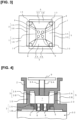
Fig. 1 is a plan view of a lower cast in an open state in a first embodiment of a low-pressure casting apparatus according to the present invention; -
Fig. 2 is a vertical cross-sectional view of a mold-open state; -
Fig. 3 is a plan view, continuing fromFig. 1 , of a lower cast in a mold-closed state; -
Fig. 4 is a vertical cross-sectional view, continuing fromFig. 2 , of a mold-closed state; -
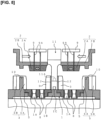
Fig. 5 is a vertical cross-sectional view of a mold-open state in a second embodiment of the low-pressure casting apparatus according to the present invention; -
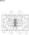
Fig. 6 is a plan view of a lower cast in a mold-open state; -
Fig. 7 is a vertical cross-sectional view, continuing fromFig. 5 , of a mold-closed state; -
Fig. 8 is a vertical cross-sectional view of a mold-closed state in a third embodiment of the low-pressure casting apparatus according to the present invention; and -
Fig. 9 is an explanatory circuit diagram of a suction mechanism of the low-pressure casting apparatus shown inFig. 8 . - A low-pressure casting apparatus shown in
Figs. 1 and 2 comprises alower mold 1 disposed on aholding furnace 50, anupper mold 2 that can be raised and lowered relative to thelower mold 1, and a plurality (four in the illustrated example) ofside molds 3 to 6 disposed on thelower mold 1. In the low-pressure casting apparatus, acavity 7, which is a casting space, is formed between thelower mold 1, theupper mold 2, and the plurality ofside molds 3 to 6, as shown inFigs. 3 and 4 .Figs. 2 and4 show onlyside molds - The
holding furnace 50, although not shown in detail, is a well-known type that stores molten metal and comprises a stalk which is a passage filled with the molten metal, an internal pressurizing mechanism, and the like. - The
lower mold 1 comprises a lower cast main part 1A that forms an inner bottom surface of thecavity 7, and a lower mold base part (die base) 1B that holds the lower cast main part 1A. The lower cast main part 1A in the illustrated example describes a square shape in a plan view, and foursprue bushes 8 are arranged vertically and horizontally in the center. Lower parts of each of thesprue bushes 8 communicate with the stalk of theholding furnace 50, and upper parts open into thecavity 7. - In the
lower mold 1 in the illustrated example, an outer periphery of the lower cast main part 1A has a downward-oriented step, the lower mold base part 1B has an upward-oriented step on an inner periphery of a portion accommodating the lower cast main part 1A, and the steps engage with one another. This allows the lower cast main part 1A and the lower mold base part 1B to be combined such that upper surfaces thereof are continuous in the same plane, and a horizontal adjustment gap S is provided therebetween. - The
upper mold 2 integrally has an upper cast main part 2A that forms an inner upper surface of thecavity 7 and an upper mold base part 2B, theupper mold 2 can be raised and lowered by a drive mechanism (not shown), and theupper mold 2 comprises amold release plate 9 provided with a plurality of mold release pins 9A passing vertically through the upper cast main part 2A. Themold release plate 9 can be raised and lowered by another drive mechanism separate from the drive mechanism of the upper mold. - At least one of the side molds 3 to 6 of the low-pressure casting apparatus according to the present invention can be advanced and retracted relative to a mold center. The
side molds 3 to 6 of the illustrated example have side castmain parts 3A-6A that form an inner side surface of thecavity 7 andplates 3B to 6B disposed on back surfaces of the side castmain parts 3A to 6A. Theside molds 3 to 6 are disposed on the four sides of thecavity 7, and can all be advanced and retracted relative to the mold center by a drive mechanism (not shown). Theside molds 3 to 6 are disposed in positions corresponding to the sides of the square-shaped lower cast main part 1A. - By contrast, the lower mold base part 1B of the
lower mold 1 has guidepillars 10 that restrict the advanced positions of the advanceable andretractable side molds 3 to 6, theguide pillars 10 being located at positions betweenadjacent side molds 3 to 6, outward of the four corners of the square-shaped lower cast main part 1A. When theside molds 3 to 6 have been advanced toward the mold center from the state shown inFig. 1 , theguide pillars 10 restrict the advanced positions of theside molds 3 to 6 due to contact being made therewith by theplates 3B to 6B of theside molds 3 to 6 as shown inFig. 3 . - In the low-pressure casting apparatus having the configuration described above, by advancing the
side molds 3 to 6 and lowering theupper mold 2 from the mold-open state shown inFigs. 1 and 2 , the mold-closed state shown inFigs. 3 and 4 is achieved and thecavity 7 is formed. The low-pressure casting apparatus then fills thecavity 7 with the molten metal in theholding furnace 50 through the stalk and thesprue bushes 8 by increasing pressure in theholding furnace 50 and reducing pressure in thecavity 7 as appropriate. After the molten metal has solidified, the molds are opened as shown inFigs. 1 and 2 , themold release plate 9 is lowered relative to theupper mold 2, and the mold release pins 9A are caused to protrude from theupper mold 2 to release a cast article. - In the low-pressure casting apparatus during the casting described above, the lower cast main part 1A, which has the
sprue bushes 8, correspondingly increases in temperature, and the lower cast main part 1A thermally expands in the horizontal direction. As a countermeasure, in the low-pressure casting apparatus, thelower mold 1 is divided into the lower cast main part 1A and the lower mold base part 1B and the adjustment gap S is provided therebetween; therefore, the thermal expansion of the lower cast main part 1A can be absorbed by the adjustment gap S and thermal deformation of the lower mold base part 1B is minimized. - As a result, in the low-pressure casting apparatus, displacement of the
guide pillars 10 in the lower mold base part 1B is prevented, proper advanced positions of the advanceable andretractable side molds 3 to 6 can be ensured due to theguide pillars 10, and there will be no gaps larger than the clearance between thelower mold 1 and theside molds 3 to 6 or between theside molds 3 to 6 and theupper mold 2. - Thus, in the low-pressure casting apparatus, excessive gaps between casts due to thermal expansion of the
lower mold 1 can be prevented, and an improvement in mold-closing accuracy can be realized. As a result, in the low-pressure casting apparatus, an improvement in dimensional accuracy of the cast articles can be realized along with the improvement in mold-closing accuracy, and it is possible to reduce the quantity of puncture defects particularly in casting using aluminum as a material. -
Figs. 5 to 9 illustrate second and third embodiments of the low-pressure casting apparatus according to the present invention. In the following embodiments, the same components as those in the first embodiment are denoted by the same symbols, and detailed descriptions thereof are omitted. - The low-pressure casting apparatus shown in
Figs. 5 and6 comprises a plurality (two in the illustrated example) of combinations of alower mold 1, anupper mold 2, and a plurality ofside molds 3 to 6. In this case, thelower mold 1 has two lower cast main parts 1A, but the lower mold base part 1A is shared. Theupper mold 2 is divided into an upper cast main part 2A and an upper mold base part 2B that form an internal upper surface of acavity 7, and the upper mold base part 2B holds the upper cast main part 2A such that the upper cast main part 2A can move back and forth in the direction in which theside molds 3 to 6 are aligned. - The upper cast main part 2A of the illustrated example can move back and forth in the direction in which the
side molds - Furthermore, the low-pressure casting apparatus comprises a center base 11 on which at least one of the side molds is positioned. The center base 11 is a structure extending from between two upper mold base parts 2B, 2B to a
lower mold 1, and the center base 11 positions twoside molds right side mold 5 in the right-side group inFig. 5 and aleft side mold 3 in the left-side group inFig. 5 . - The center base 11 may be configured to be capable of being raised and lowered via a drive mechanism (not shown), and by causing a recess 11A provided at a lower end of the center base to engage with a protrusion 1C of the lower mold base part 1B, the center base 11 is positioned in the horizontal direction.
- In the low-pressure casting apparatus, the center base 11 and the
side molds side molds - The center base 11 can also constitute a center mold that includes the
side molds lower mold 1 and theupper mold 2 described above, theside molds cavity 7, and the center base 11 is equivalent to a center mold base part. This results in a structure in which the center mold is divided into side cast main parts (3 and 5) and center mold base part (11), and an adjustment shim 12 can be interposed therebetween. - In the low-pressure casting apparatus comprising the above configuration, as in the first embodiment, due to the adjustment gaps S provided between the lower cast main parts 1A and 1A and the lower mold base part 1B in the
lower mold 1, thermal expansion of the lower cast main parts 1A and 1A can be absorbed to minimize thermal expansion of the lower mold base part 1B, and shifting of the positions of theguide pillars 10 and the advanced positions of the advanceable andretractable side molds - In the low-pressure casting apparatus described above, the
upper molds 2 are divided into upper cast main parts 2A and upper mold base parts 2B, the upper mold base parts 2B are pushed against the center base 11, and the lower cast main parts 2A can move back and forth relative to the upper mold base parts 2B. - This allows the upper cast main parts 2A of the low-pressure casting apparatus to move in opposite directions (the directions of the arrows) relative to the center base 11 during mold closing as shown in
Fig. 7 ; therefore, the upper cast main parts 2A can be corrected to the proper mold-closing positions and further improvement in mold-closing accuracy can be realized. - Furthermore, by using the center base 11 and the adjustment shim 12 for positioning the two
side molds side molds side molds - Furthermore, in the low-pressure casting apparatus described above, the use of the center base 11 eliminates the need for drive mechanisms to position the
side molds - The low-pressure casting apparatus shown in
Fig. 8 has the same basic configuration as that of the second embodiment (Figs. 5 to 7 ). Exhaust passages P1 for discharging air in thecavity 7 are located between thelower mold 1 and theside molds suction mechanism 60 is provided to suction air out of thecavity 7 through the exhaust passages P. - Well-known chill vents may be used for the exhaust passages P. The
suction mechanism 60, as shown inFig. 9 , has two exhaust pipes 61A and 61B, each connected to a respective exhaust passage P of the low-pressure casting apparatus. The exhaust pipes 61A and 61B are connected to a suction source 62 constituted of a vacuum pump or a vacuum tank, pressure adjustment valves V1, V2 and exhaust valves V3 are provided partway along the exhaust pipes, and the suction source 62 and the valves V1-V3 are controlled on the basis of values measured by pressure gauges M1, M2 for thecavities - As described in the first and second embodiments, the low-pressure casting apparatus comprising the above configuration has favorable mold-closing accuracy, and it is therefore possible to differentiate between the exhaust passages P and the general clearance between molds. As a result, the low-pressure casting apparatus has no unnecessary gaps between molds, so the air in the
cavity 7 can be intentionally suctioned out and discharged to a favorable degree using the exhaust passages P, and a degree of vacuum in thecavity 7 can be increased without enclosing the entire casting apparatus in a large housing. The low-pressure casting apparatus also enables low-pressure casting using a multi-cavity mold, and can favorably produce thin-walled castings. - The configuration of the low-pressure casting apparatus according to the present invention is not limited to only the embodiments above; changes can be made as appropriate within a range that does not deviate from the scope of the invention, and the present invention can naturally also be applied to castings or the like using a core.
-
- 1
- Lower mold
- 1A
- Lower cast main part
- 1B
- Lower mold base part
- 2
- Upper mold
- 2A
- Upper cast main part
- 2B
- Upper mold base part
- 3 to 6
- Side molds
- 7
- Cavity
- 8
- Sprue bushing
- 10
- Guide pillar
- 11
- Center base
- 12
- Adjustment shim
- 50
- Holding furnace
- 60
- Suction mechanism
- P
- Exhaust passage
- S
- Adjustment gap
Claims (4)
- A low-pressure casting apparatus comprising:a lower mold disposed on a holding furnace;an upper mold configured to be raised and lowered relative to the lower mold; anda plurality of side molds disposed above the lower mold,a cavity being formed between the lower mold, the upper mold and the side molds,the lower mold including a lower cast main part forming an inner bottom surface of the cavity, and a lower mold base part holding the lower cast main part,the lower cast main part having a sprue bushing that opens into the cavity,at least one of the side molds being advanceable and retractable relative to a mold center, the lower mold base part having guide pillars that restrict advanced positions of the advanceable and retractable side molds, anda horizontal adjustment gap being provided between the lower cast main part and the lower mold base part.
- The low-pressure casting apparatus according to claim 1, further comprising a plurality of combinations of the lower mold, the upper mold, and the plurality of side molds,
the upper mold including an upper cast main part that forms an inner upper surface of the cavity, and an upper mold base part that holds the upper cast main part such that the upper cast main part is configured to move back and forth in a direction in which the side molds are aligned. - The low-pressure casting apparatus according to claim 2, further comprising a center base that positions at least one of the side molds,
the center base and the side mold positioned by the center base being separated from each other such that an adjustment shim can be interposed therebetween. - The low-pressure casting apparatus according to any one of claims 1 to 3, wherein exhaust passages for discharging air in the cavity are located between the upper mold and the side molds, and
a suction mechanism is provided to suction air out of the cavity through the exhaust passages.
Applications Claiming Priority (1)
| Application Number | Priority Date | Filing Date | Title |
|---|---|---|---|
| PCT/JP2022/019520 WO2023214452A1 (en) | 2022-05-02 | 2022-05-02 | Low-pressure casting apparatus |
Publications (3)
| Publication Number | Publication Date |
|---|---|
| EP4520455A1 true EP4520455A1 (en) | 2025-03-12 |
| EP4520455A4 EP4520455A4 (en) | 2025-07-02 |
| EP4520455B1 EP4520455B1 (en) | 2026-02-11 |
Family
ID=88646395
Family Applications (1)
| Application Number | Title | Priority Date | Filing Date |
|---|---|---|---|
| EP22940505.5A Active EP4520455B1 (en) | 2022-05-02 | 2022-05-02 | Low-pressure casting apparatus |
Country Status (5)
| Country | Link |
|---|---|
| US (1) | US12605760B2 (en) |
| EP (1) | EP4520455B1 (en) |
| JP (1) | JP7750401B2 (en) |
| CN (1) | CN119095680B (en) |
| WO (1) | WO2023214452A1 (en) |
Family Cites Families (19)
| Publication number | Priority date | Publication date | Assignee | Title |
|---|---|---|---|---|
| US4824351A (en) * | 1987-10-14 | 1989-04-25 | Matrix Technologies, Incorporated | Molding and gauging system |
| JPH01109357U (en) * | 1988-01-08 | 1989-07-24 | ||
| JPH0810448Y2 (en) * | 1990-08-31 | 1996-03-29 | マツダ株式会社 | Casting mold equipment |
| JP3808167B2 (en) * | 1997-05-01 | 2006-08-09 | Ykk株式会社 | Method and apparatus for manufacturing amorphous alloy molded article formed by pressure casting with mold |
| JP4520579B2 (en) | 2000-04-10 | 2010-08-04 | 本田技研工業株式会社 | Molding equipment for casting |
| JP4430412B2 (en) * | 2004-01-21 | 2010-03-10 | ヤマハ発動機株式会社 | Casting machine |
| JP2007050435A (en) * | 2005-08-19 | 2007-03-01 | Toyota Motor Corp | Mold for casting |
| JP2007319891A (en) | 2006-05-31 | 2007-12-13 | Toyota Motor Corp | Low pressure casting equipment |
| CN201677021U (en) * | 2010-03-01 | 2010-12-22 | 何灿东 | Low-pressure casting hub die |
| JP5727913B2 (en) * | 2011-10-17 | 2015-06-03 | 本田技研工業株式会社 | Mold positioning mechanism |
| CN203508996U (en) * | 2013-09-04 | 2014-04-02 | 广东中兴液力传动有限公司 | Low-pressure casting mold of hydraulic coupling impeller |
| US9352384B2 (en) | 2014-05-27 | 2016-05-31 | Honda Motor Co., Ltd. | Cylinder head casting apparatus and methods |
| JP6596921B2 (en) | 2015-05-21 | 2019-10-30 | 日産自動車株式会社 | Method for controlling molten metal filling in casting apparatus |
| WO2016185610A1 (en) * | 2015-05-21 | 2016-11-24 | 日産自動車株式会社 | Pressure controlling method for casting apparatus |
| MX364037B (en) * | 2015-05-29 | 2019-04-11 | Nissan Motor | Device for casting cylinder head and method for casting cylinder head. |
| CN205496515U (en) * | 2016-04-21 | 2016-08-24 | 江苏新安驰铝业有限公司 | Overall wheel hub casting mould |
| JP7135505B2 (en) * | 2018-07-03 | 2022-09-13 | 日産自動車株式会社 | Casting mold device and low-pressure casting method |
| CN211000145U (en) * | 2019-08-30 | 2020-07-14 | 山东泰开精密铸造有限公司 | Low pressure mold structure |
| CN110695339B (en) * | 2019-10-12 | 2021-09-03 | 保定市立中车轮制造有限公司 | Five-open type side die hub casting die |
-
2022
- 2022-05-02 EP EP22940505.5A patent/EP4520455B1/en active Active
- 2022-05-02 CN CN202280095491.5A patent/CN119095680B/en active Active
- 2022-05-02 US US18/861,623 patent/US12605760B2/en active Active
- 2022-05-02 JP JP2024519154A patent/JP7750401B2/en active Active
- 2022-05-02 WO PCT/JP2022/019520 patent/WO2023214452A1/en not_active Ceased
Also Published As
| Publication number | Publication date |
|---|---|
| JPWO2023214452A1 (en) | 2023-11-09 |
| CN119095680B (en) | 2025-11-11 |
| EP4520455B1 (en) | 2026-02-11 |
| US20250256326A1 (en) | 2025-08-14 |
| CN119095680A (en) | 2024-12-06 |
| JP7750401B2 (en) | 2025-10-07 |
| EP4520455A4 (en) | 2025-07-02 |
| WO2023214452A1 (en) | 2023-11-09 |
| US12605760B2 (en) | 2026-04-21 |
Similar Documents
| Publication | Publication Date | Title |
|---|---|---|
| CN101842176B (en) | Casting mold device | |
| CN105142822B (en) | Mold | |
| US3596708A (en) | Locking mechanism for diecasting | |
| KR100979665B1 (en) | Injection molding of thin sheet | |
| PT2070675E (en) | Mould equipped with a locking device | |
| JP5727913B2 (en) | Mold positioning mechanism | |
| US12605760B2 (en) | Low-pressure casting apparatus | |
| CN110248793A (en) | Mold for forming | |
| US8997834B2 (en) | Method for producing of hollow die cast products | |
| KR102726375B1 (en) | Apparatus and method for manufacturing upper cover of hybrid power control unit | |
| CN111225754B (en) | Die-casting moulds for casting cylinder crankcases or crankcase parts | |
| JP4780621B2 (en) | Light guide plate injection press molding method | |
| CN101518817A (en) | Die for die casting and method of manufacturing cast product | |
| JP2019209334A (en) | Die-casting die molding foot step of passenger conveyor | |
| CN111050948B (en) | casting device | |
| KR20240030417A (en) | Diecasting mold for cooling device of power semiconductor module | |
| JPH06312252A (en) | Mold structure of casting equipment | |
| JP4257167B2 (en) | Cylinder head manufacturing method and apparatus | |
| JP5610747B2 (en) | Molded product manufacturing method and injection mold | |
| KR20250059436A (en) | Counter piston central injection die casting | |
| JP7639670B2 (en) | Mold Equipment | |
| JP4637609B2 (en) | Chill vent nesting | |
| JP2006062204A (en) | Mold equipment for molding | |
| KR102555462B1 (en) | High-pressure die-casting device for manufacturing VCU housing | |
| JPH07116808A (en) | Die casting mold |
Legal Events
| Date | Code | Title | Description |
|---|---|---|---|
| STAA | Information on the status of an ep patent application or granted ep patent |
Free format text: STATUS: THE INTERNATIONAL PUBLICATION HAS BEEN MADE |
|
| PUAI | Public reference made under article 153(3) epc to a published international application that has entered the european phase |
Free format text: ORIGINAL CODE: 0009012 |
|
| STAA | Information on the status of an ep patent application or granted ep patent |
Free format text: STATUS: REQUEST FOR EXAMINATION WAS MADE |
|
| 17P | Request for examination filed |
Effective date: 20241122 |
|
| AK | Designated contracting states |
Kind code of ref document: A1 Designated state(s): AL AT BE BG CH CY CZ DE DK EE ES FI FR GB GR HR HU IE IS IT LI LT LU LV MC MK MT NL NO PL PT RO RS SE SI SK SM TR |
|
| A4 | Supplementary search report drawn up and despatched |
Effective date: 20250602 |
|
| RIC1 | Information provided on ipc code assigned before grant |
Ipc: B22D 18/04 20060101AFI20250526BHEP |
|
| DAV | Request for validation of the european patent (deleted) | ||
| DAX | Request for extension of the european patent (deleted) | ||
| GRAP | Despatch of communication of intention to grant a patent |
Free format text: ORIGINAL CODE: EPIDOSNIGR1 |
|
| STAA | Information on the status of an ep patent application or granted ep patent |
Free format text: STATUS: GRANT OF PATENT IS INTENDED |
|
| INTG | Intention to grant announced |
Effective date: 20251001 |
|
| GRAS | Grant fee paid |
Free format text: ORIGINAL CODE: EPIDOSNIGR3 |
|
| GRAA | (expected) grant |
Free format text: ORIGINAL CODE: 0009210 |
|
| STAA | Information on the status of an ep patent application or granted ep patent |
Free format text: STATUS: THE PATENT HAS BEEN GRANTED |
|
| AK | Designated contracting states |
Kind code of ref document: B1 Designated state(s): AL AT BE BG CH CY CZ DE DK EE ES FI FR GB GR HR HU IE IS IT LI LT LU LV MC MK MT NL NO PL PT RO RS SE SI SK SM TR |
|
| REG | Reference to a national code |
Ref country code: CH Ref legal event code: F10 Free format text: ST27 STATUS EVENT CODE: U-0-0-F10-F00 (AS PROVIDED BY THE NATIONAL OFFICE) Effective date: 20260211 Ref country code: GB Ref legal event code: FG4D |
|
| REG | Reference to a national code |
Ref country code: DE Ref legal event code: R096 Ref document number: 602022030387 Country of ref document: DE |
|
| REG | Reference to a national code |
Ref country code: IE Ref legal event code: FG4D |
|
| REG | Reference to a national code |
Ref country code: NL Ref legal event code: MP Effective date: 20260211 |
|
| PG25 | Lapsed in a contracting state [announced via postgrant information from national office to epo] |
Ref country code: RS Free format text: LAPSE BECAUSE OF FAILURE TO SUBMIT A TRANSLATION OF THE DESCRIPTION OR TO PAY THE FEE WITHIN THE PRESCRIBED TIME-LIMIT Effective date: 20260511 |
|
| PG25 | Lapsed in a contracting state [announced via postgrant information from national office to epo] |
Ref country code: ES Free format text: LAPSE BECAUSE OF FAILURE TO SUBMIT A TRANSLATION OF THE DESCRIPTION OR TO PAY THE FEE WITHIN THE PRESCRIBED TIME-LIMIT Effective date: 20260211 |
|
| PG25 | Lapsed in a contracting state [announced via postgrant information from national office to epo] |
Ref country code: PL Free format text: LAPSE BECAUSE OF FAILURE TO SUBMIT A TRANSLATION OF THE DESCRIPTION OR TO PAY THE FEE WITHIN THE PRESCRIBED TIME-LIMIT Effective date: 20260211 |
|
| PG25 | Lapsed in a contracting state [announced via postgrant information from national office to epo] |
Ref country code: GR Free format text: LAPSE BECAUSE OF FAILURE TO SUBMIT A TRANSLATION OF THE DESCRIPTION OR TO PAY THE FEE WITHIN THE PRESCRIBED TIME-LIMIT Effective date: 20260512 |
|
| REG | Reference to a national code |
Ref country code: LT Ref legal event code: MG9D |
|
| PG25 | Lapsed in a contracting state [announced via postgrant information from national office to epo] |
Ref country code: LT Free format text: LAPSE BECAUSE OF FAILURE TO SUBMIT A TRANSLATION OF THE DESCRIPTION OR TO PAY THE FEE WITHIN THE PRESCRIBED TIME-LIMIT Effective date: 20260211 |
|
| PGFP | Annual fee paid to national office [announced via postgrant information from national office to epo] |
Ref country code: DE Payment date: 20260520 Year of fee payment: 5 |
|
| PG25 | Lapsed in a contracting state [announced via postgrant information from national office to epo] |
Ref country code: NO Free format text: LAPSE BECAUSE OF FAILURE TO SUBMIT A TRANSLATION OF THE DESCRIPTION OR TO PAY THE FEE WITHIN THE PRESCRIBED TIME-LIMIT Effective date: 20260511 |
|
| PG25 | Lapsed in a contracting state [announced via postgrant information from national office to epo] |
Ref country code: FI Free format text: LAPSE BECAUSE OF FAILURE TO SUBMIT A TRANSLATION OF THE DESCRIPTION OR TO PAY THE FEE WITHIN THE PRESCRIBED TIME-LIMIT Effective date: 20260211 Ref country code: AT Free format text: LAPSE BECAUSE OF FAILURE TO SUBMIT A TRANSLATION OF THE DESCRIPTION OR TO PAY THE FEE WITHIN THE PRESCRIBED TIME-LIMIT Effective date: 20260211 Ref country code: SE Free format text: LAPSE BECAUSE OF FAILURE TO SUBMIT A TRANSLATION OF THE DESCRIPTION OR TO PAY THE FEE WITHIN THE PRESCRIBED TIME-LIMIT Effective date: 20260211 |
|
| REG | Reference to a national code |
Ref country code: AT Ref legal event code: MK05 Ref document number: 1885287 Country of ref document: AT Kind code of ref document: T Effective date: 20260211 |
|
| PG25 | Lapsed in a contracting state [announced via postgrant information from national office to epo] |
Ref country code: HR Free format text: LAPSE BECAUSE OF FAILURE TO SUBMIT A TRANSLATION OF THE DESCRIPTION OR TO PAY THE FEE WITHIN THE PRESCRIBED TIME-LIMIT Effective date: 20260211 |
|
| PG25 | Lapsed in a contracting state [announced via postgrant information from national office to epo] |
Ref country code: IS Free format text: LAPSE BECAUSE OF FAILURE TO SUBMIT A TRANSLATION OF THE DESCRIPTION OR TO PAY THE FEE WITHIN THE PRESCRIBED TIME-LIMIT Effective date: 20260611 Ref country code: PT Free format text: LAPSE BECAUSE OF FAILURE TO SUBMIT A TRANSLATION OF THE DESCRIPTION OR TO PAY THE FEE WITHIN THE PRESCRIBED TIME-LIMIT Effective date: 20260611 |
|
| PG25 | Lapsed in a contracting state [announced via postgrant information from national office to epo] |
Ref country code: NL Free format text: LAPSE BECAUSE OF FAILURE TO SUBMIT A TRANSLATION OF THE DESCRIPTION OR TO PAY THE FEE WITHIN THE PRESCRIBED TIME-LIMIT Effective date: 20260211 |
|
| PG25 | Lapsed in a contracting state [announced via postgrant information from national office to epo] |
Ref country code: LV Free format text: LAPSE BECAUSE OF FAILURE TO SUBMIT A TRANSLATION OF THE DESCRIPTION OR TO PAY THE FEE WITHIN THE PRESCRIBED TIME-LIMIT Effective date: 20260211 |
|
| PG25 | Lapsed in a contracting state [announced via postgrant information from national office to epo] |
Ref country code: BG Free format text: LAPSE BECAUSE OF FAILURE TO SUBMIT A TRANSLATION OF THE DESCRIPTION OR TO PAY THE FEE WITHIN THE PRESCRIBED TIME-LIMIT Effective date: 20260211 |