EP4520382A1 - Transfer instrument - Google Patents
Transfer instrument Download PDFInfo
- Publication number
- EP4520382A1 EP4520382A1 EP23816138.4A EP23816138A EP4520382A1 EP 4520382 A1 EP4520382 A1 EP 4520382A1 EP 23816138 A EP23816138 A EP 23816138A EP 4520382 A1 EP4520382 A1 EP 4520382A1
- Authority
- EP
- European Patent Office
- Prior art keywords
- shaft
- outer cylinder
- pressing
- support portion
- transfer instrument
- Prior art date
- Legal status (The legal status is an assumption and is not a legal conclusion. Google has not performed a legal analysis and makes no representation as to the accuracy of the status listed.)
- Pending
Links
Images








Classifications
-
- A—HUMAN NECESSITIES
- A61—MEDICAL OR VETERINARY SCIENCE; HYGIENE
- A61M—DEVICES FOR INTRODUCING MEDIA INTO, OR ONTO, THE BODY; DEVICES FOR TRANSDUCING BODY MEDIA OR FOR TAKING MEDIA FROM THE BODY; DEVICES FOR PRODUCING OR ENDING SLEEP OR STUPOR
- A61M37/00—Other apparatus for introducing media into the body; Percutany, i.e. introducing medicines into the body by diffusion through the skin
-
- A—HUMAN NECESSITIES
- A61—MEDICAL OR VETERINARY SCIENCE; HYGIENE
- A61F—FILTERS IMPLANTABLE INTO BLOOD VESSELS; PROSTHESES; DEVICES PROVIDING PATENCY TO, OR PREVENTING COLLAPSING OF, TUBULAR STRUCTURES OF THE BODY, e.g. STENTS; ORTHOPAEDIC, NURSING OR CONTRACEPTIVE DEVICES; FOMENTATION; TREATMENT OR PROTECTION OF EYES OR EARS; BANDAGES, DRESSINGS OR ABSORBENT PADS; FIRST-AID KITS
- A61F2/00—Filters implantable into blood vessels; Prostheses, i.e. artificial substitutes or replacements for parts of the body; Appliances for connecting them with the body; Devices providing patency to, or preventing collapsing of, tubular structures of the body, e.g. stents
-
- A—HUMAN NECESSITIES
- A61—MEDICAL OR VETERINARY SCIENCE; HYGIENE
- A61B—DIAGNOSIS; SURGERY; IDENTIFICATION
- A61B1/00—Instruments for performing medical examinations of the interior of cavities or tubes of the body by visual or photographical inspection, e.g. endoscopes; Illuminating arrangements therefor
- A61B1/00064—Constructional details of the endoscope body
- A61B1/00071—Insertion part of the endoscope body
- A61B1/0008—Insertion part of the endoscope body characterised by distal tip features
- A61B1/00087—Tools
-
- A—HUMAN NECESSITIES
- A61—MEDICAL OR VETERINARY SCIENCE; HYGIENE
- A61B—DIAGNOSIS; SURGERY; IDENTIFICATION
- A61B17/00—Surgical instruments, devices or methods
- A61B17/00234—Surgical instruments, devices or methods for minimally invasive surgery
-
- A—HUMAN NECESSITIES
- A61—MEDICAL OR VETERINARY SCIENCE; HYGIENE
- A61F—FILTERS IMPLANTABLE INTO BLOOD VESSELS; PROSTHESES; DEVICES PROVIDING PATENCY TO, OR PREVENTING COLLAPSING OF, TUBULAR STRUCTURES OF THE BODY, e.g. STENTS; ORTHOPAEDIC, NURSING OR CONTRACEPTIVE DEVICES; FOMENTATION; TREATMENT OR PROTECTION OF EYES OR EARS; BANDAGES, DRESSINGS OR ABSORBENT PADS; FIRST-AID KITS
- A61F2/00—Filters implantable into blood vessels; Prostheses, i.e. artificial substitutes or replacements for parts of the body; Appliances for connecting them with the body; Devices providing patency to, or preventing collapsing of, tubular structures of the body, e.g. stents
- A61F2/0095—Packages or dispensers for prostheses or other implants
-
- A—HUMAN NECESSITIES
- A61—MEDICAL OR VETERINARY SCIENCE; HYGIENE
- A61B—DIAGNOSIS; SURGERY; IDENTIFICATION
- A61B17/00—Surgical instruments, devices or methods
- A61B17/00234—Surgical instruments, devices or methods for minimally invasive surgery
- A61B2017/00292—Surgical instruments, devices or methods for minimally invasive surgery mounted on or guided by flexible, e.g. catheter-like, means
- A61B2017/00296—Surgical instruments, devices or methods for minimally invasive surgery mounted on or guided by flexible, e.g. catheter-like, means mounted on an endoscope
-
- A—HUMAN NECESSITIES
- A61—MEDICAL OR VETERINARY SCIENCE; HYGIENE
- A61B—DIAGNOSIS; SURGERY; IDENTIFICATION
- A61B17/00—Surgical instruments, devices or methods
- A61B2017/00681—Aspects not otherwise provided for
- A61B2017/00738—Aspects not otherwise provided for part of the tool being offset with respect to a main axis, e.g. for better view for the surgeon
-
- A—HUMAN NECESSITIES
- A61—MEDICAL OR VETERINARY SCIENCE; HYGIENE
- A61B—DIAGNOSIS; SURGERY; IDENTIFICATION
- A61B17/00—Surgical instruments, devices or methods
- A61B2017/00969—Surgical instruments, devices or methods used for transplantation
-
- A—HUMAN NECESSITIES
- A61—MEDICAL OR VETERINARY SCIENCE; HYGIENE
- A61F—FILTERS IMPLANTABLE INTO BLOOD VESSELS; PROSTHESES; DEVICES PROVIDING PATENCY TO, OR PREVENTING COLLAPSING OF, TUBULAR STRUCTURES OF THE BODY, e.g. STENTS; ORTHOPAEDIC, NURSING OR CONTRACEPTIVE DEVICES; FOMENTATION; TREATMENT OR PROTECTION OF EYES OR EARS; BANDAGES, DRESSINGS OR ABSORBENT PADS; FIRST-AID KITS
- A61F2/00—Filters implantable into blood vessels; Prostheses, i.e. artificial substitutes or replacements for parts of the body; Appliances for connecting them with the body; Devices providing patency to, or preventing collapsing of, tubular structures of the body, e.g. stents
- A61F2/0063—Implantable repair or support meshes, e.g. hernia meshes
- A61F2002/0072—Delivery tools therefor
Definitions
- the present invention relates to a transfer instrument.
- JP 2009-511 A discloses a transfer instrument for transferring a medical sheet (cell sheet) for use in, for example, organ transplantation to a treatment site of a living body.
- the transfer instrument includes a shaft and a support portion provided at a distal portion of the shaft.
- the support portion includes a support surface on which the medical sheet is placed.
- the transfer instrument is slid with an upper surface of the medical sheet placed on the support surface pressed with forceps or the like to transfer the medical sheet from the support portion to the treatment site.
- the above-described related art requires that, when transferring the medical sheet from the support portion to the treatment site of the living body, the transfer instrument be manipulated with the upper surface of the medical sheet pressed with forceps or the like, so that there is possibility that the medical sheet cannot be efficiently transferred to the treatment site.
- a transfer instrument 10 is a medical instrument for transferring a medical sheet 300 to a treatment site of a living body.
- the transfer instrument 10 is used for, for example, the treatment of severe heart failure caused by ischemic heart disease.
- the medical sheet 300 is transplanted to a recipient site 402 of a heart 400 (the treatment site of the living body) (see Figs. 12 to 15 ).
- the transfer instrument 10 is capable of attaching a plurality of the medical sheets 300 to the recipient site 402.
- Examples of such a medical sheet 300 include pharmaceutical products or regenerative medicine products for medical use, a medical instrument, and the like.
- the medical sheet 300 is formed in a sheet shape such as a film shape or a membrane shape (high viscosity object). Fibrin or the like may be applied to the medical sheet 300 for reinforcement.
- Examples of the regenerative medicine products including cells include a cell sheet (sheet-shaped cell culture), a spheroid (multicellular spheroid ), and the like. It is possible to form the cell sheet by culturing autologous cells or allogenic cells.
- the cells constituting the cell sheet include, for example, somatic stem cells (adult stem cells), mesenchymal stem cells, or iPS cells (induced pluripotent stem cells)-derived cardiomyocytes. Examples of the somatic stem cells preferably include skeletal myoblast cells (myoblast cells).
- the medical sheet 300 may contain a tissue adhesive, a local anesthetic, or the like.
- the medical sheet 300 has a thickness of, for example, about 100 ⁇ m, and has a diameter of, for example, about 60 mm. Note that the thickness and the diameter (size) of the medical sheet 300 can be set as desired.
- the medical sheet 300 may be a sheet to be transplanted to an organ (for example, lung, liver, pancreas, kidney, small intestine, esophagus, or the like) other than the heart 400. Further, the medical sheet 300 may be, for example, an anti-adhesion sheet as long as the sheet is for medical use.
- an organ for example, lung, liver, pancreas, kidney, small intestine, esophagus, or the like
- an anti-adhesion sheet as long as the sheet is for medical use.
- the transfer instrument 10 includes an instrument body 12, an endoscope 14, and a fixing member 16.
- the instrument body 12 includes a first carrier member 18, a second carrier member 20, and an outer cylinder 22.
- the first carrier member 18 includes a first shaft 24 and a support portion 26.
- the first shaft 24 is a circular tube member having a first lumen 28.
- the first lumen 28 opens at a distal end (end in a direction of arrow X1) of the first shaft 24 and opens at a proximal end (end in a direction of arrow X2) of the first shaft 24.
- the first shaft 24 includes, for example, a resin material.
- the constituent material of the first shaft 24 include, but not particularly limited to, polyethylene, polypropylene, fluororesin, polyethylene terephthalate, polymethyl methacrylate, polyamide resin, polystyrene, polycarbonate, polyimide, polyetherimide, polyetheretherketone, polyvinyl chloride, and ABS resin.
- the first shaft 24 may include a metal material.
- the first shaft 24 may be flexible.
- the first shaft 24 may include a flexible tube portion capable of retaining a bent shape.
- the first shaft 24 can be bent into an any desired shape in a body cavity and can retaining the bent shape.
- the flexible tube portion is formed by, for example, forming a tube wall portion in a pleated shape.
- the flexible tube portion may include a material capable of retaining a bent shape.
- the flexible tube portion can be formed, for example, by inserting a linear metal member capable of retaining a bent shape into the lumen of the first shaft 24 including resin.
- the flexible tube portion forms only a part of the first shaft 24 in a longitudinal direction. Note that the flexible tube portion may form the entire first shaft 24.
- the support portion 26 is attached to a distal portion of the first shaft 24.
- the support portion 26 includes, for example, a resin material.
- the constituent material of the support portion 26 preferably has transparency, and examples of the constituent material include, but not particularly limited to, polycarbonate, polyamide, polystyrene, polypropylene, polyacetal resin, polyimide, polyetheretherketone, polyethylene terephthalate, and fluororesin.
- the support portion 26 is flexible.
- a resin sheet member (film member) is bent into a predetermined form to form the support portion 26.
- the sheet member is shaped into a predetermined form by a sheet forming die to form the support portion 26. It is preferable that the sheet member have, but not particularly limited to, a thickness of, for example, 100 ⁇ m or more and 200 ⁇ m or less.
- the support portion 26 includes a joint 30 and a support body 32.
- the joint 30 is bonded to an inner peripheral surface of the distal portion of the first shaft 24 with an adhesive.
- the adhesive include, but not particularly limited to, a UV adhesive and an instant adhesive (for example, cyanoacrylate-based instant adhesive).
- the joint 30 may be thermally fused to the inner peripheral surface of the first shaft 24.
- the joint 30 does not form a step on an outer peripheral surface of the first shaft 24, so that the first shaft 24 can be smoothly inserted into the outer cylinder 22.
- the joint 30 may be joined to a lower surface (an outer surface facing the direction of arrow Y1) of the distal portion of the first shaft 24.
- the support body 32 extends in a distal end direction from the joint 30 (see Fig. 4 ).
- the support body 32 includes a proximal-end support portion 34, a pair of first protrusions 36, an intermediate support portion 38, a pair of second protrusions 40, a pair of third protrusions 42, and a distal-end support portion 44.
- the proximal-end support portion 34 extends roughly along an axis Ax of the first shaft 24 from a distal end of the joint 30 in the distal end direction (see Fig. 4 ).
- the proximal-end support portion 34 is formed to be wider in its extending direction. In other words, both sides of the proximal-end support portion 34 in a width direction are tapered toward the joint 30.
- the pair of first protrusions 36 protrude upward (in a direction of arrow Y2) from both the sides of the proximal-end support portion 34.
- the intermediate support portion 38 extends from a distal end of the proximal-end support portion 34 in the distal end direction at an angle relative to the proximal-end support portion 34 so as to approach the axis Ax of the first shaft 24 (see Fig. 4 ).
- the intermediate support portion 38 is formed with a substantially constant width over the entire length. Note that the intermediate support portion 38 may be formed to be wider or narrower in the distal end direction.
- the pair of second protrusions 40 are connected to distal ends of the pair of first protrusions 36.
- the pair of second protrusions 40 protrude upward from both sides of the intermediate support portion 38 in the width direction and inward in the width direction of the intermediate support portion 38.
- the pair of third protrusions 42 are connected to distal ends of the pair of second protrusions 40.
- the pair of third protrusions 42 protrude upward from both the sides of the intermediate support portion 38 in the width direction and outward in the width direction of the intermediate support portion 38.
- the distal-end support portion 44 is connected to a distal end of the intermediate support portion 38 and distal ends of the pair of third protrusions 42.
- the distal-end support portion 44 protrudes in an arc shape in the distal end direction. In other words, the distal-end support portion 44 is formed to be narrower in the distal end direction.
- the support body 32 includes a support surface 46 facing upward.
- the support surface 46 is formed by an upper surface of the intermediate support portion 38, an upper surface of the distal-end support portion 44, and upper surfaces of the pair of third protrusions 42.
- a lubricant may be applied to the support surface 46 so as to allow a pressing portion 50 (to be described later) of the second carrier member 20 to smoothly slide on the support surface 46.
- a part of the support surface 46 formed by the upper surface of the intermediate support portion 38 and the upper surface of the distal-end support portion 44 is a flat surface (see Fig. 4 ). Note that the part of the support surface 46 formed by the upper surface of the intermediate support portion 38 and the upper surface of the distal-end support portion 44 may be a curved surface that curves in a direction opposite to the direction that the support surface 46 faces.
- the second carrier member 20 includes a second shaft 54, the pressing portion 50, and a connector 52.
- the second shaft 54 is a circular tube member having a second lumen 57.
- the second lumen 57 opens at a distal end (end in the direction of arrow X1) of the second shaft 54 and opens at a proximal end (end in the direction of arrow X2) of the second shaft 54.
- the second shaft 54 is longer in the axial direction than the first shaft 24.
- the second shaft 54 is inserted into the first lumen 28 of the first shaft 24 (see Figs. 1 and 4 ).
- a distal portion of the second shaft 54 protrudes in the distal end direction relative to a distal-end opening of the first shaft 24.
- a proximal portion of the second shaft 54 protrudes in the proximal end direction relative to a proximal-end opening of the first shaft 24 (see Fig. 1 ).
- the second shaft 54 is configured to follow the shape (angle) of the support portion 26.
- a material more flexible than the constituent material of the first shaft 24 is selected.
- the constituent material of the second shaft 54 include a polyamide elastomer, a polyester elastomer, a polyurethane elastomer, polyvinyl chloride, polybutadiene, a silicone rubber, and a metal coil (including a composite with a resin).
- the second shaft 54 is flexible. Note that in a case where the first shaft 24 includes the flexible tube portion, the second shaft 54 bends along the bent shape of the first shaft 24.
- the pressing portion 50 is attached to the distal portion of the second shaft 54.
- an insertion hole 58, a pressing surface 64, and a supply hole 66 are formed in the pressing portion 50.
- the distal portion of the second shaft 54 is inserted into the insertion hole 58.
- the distal portion of the second shaft 54 is thermally fused to an inner surface forming the insertion hole 58.
- the distal portion of the second shaft 54 may be joined to the inner surface forming the insertion hole 58 with an adhesive.
- the pressing portion 50 is formed to be wider in the distal end direction when viewed from above.
- the pressing portion 50 is formed in a trapezoidal shape when viewed from above.
- the pressing surface 64 is provided on a distal end surface of the pressing portion 50.
- the pressing surface 64 presses an outer edge surface 302 (see Fig. 14 ) of the medical sheet 300 in the distal end direction.
- the pressing surface 64 extends upward with an inclination in the distal end direction (the direction of arrow X1).
- the pressing surface 64 includes a flat surface.
- the supply hole 66 communicates with the second lumen 57 of the second shaft 54 and opens to the pressing surface 64.
- the supply hole 66 and the second lumen 57 communicate with each other to form a liquid supply flow path 68.
- the liquid supply flow path 68 guides, toward a distal end of the pressing portion 50, a liquid for preventing the medical sheet 300 from drying out.
- a physiological saline solution is used as the liquid.
- the connector 52 is attached to the proximal portion of the second shaft 54.
- the connector 52 is configured as a so-called straight connector.
- the connector 52 includes a connection port 82 to which a liquid supply instrument (not illustrated) is detachably attached.
- the outer cylinder 22 is a cylindrical member having a lumen 84.
- the lumen 84 opens at a distal end (end in the direction of arrow X1) of the outer cylinder 22 and opens at a proximal end (end in the direction of arrow X2) of the outer cylinder 22.
- the outer cylinder 22 is flexible. Examples of the constituent material of the outer cylinder 22 are the same as the examples of the constituent material of the first shaft 24 described above. Note that in a case where the first shaft 24 includes the flexible tube portion, the outer cylinder 22 bends along the bent shape of the first shaft 24. Further, in the present embodiment, the outer cylinder 22 may include the flexible tube portion as described above. In this case, the first shaft 24 need not include the flexible tube portion.
- the first shaft 24 is inserted into the lumen 84 of the outer cylinder 22.
- the outer cylinder 22 is shorter in the axial direction than the first shaft 24.
- an inner diameter D1 of the outer cylinder 22 is smaller than the width W1 of the intermediate support portion 38.
- the width W1 of the intermediate support portion 38 is substantially identical to a circumferential length of an inner surface of the outer cylinder 22 so as to allow the support portion 26 to be retracted into the outer cylinder 22 with the support portion 26 curled into a cylinder along a circumferential direction of an inner peripheral surface of the outer cylinder 22.
- the width W1 may be shorter or longer than the circumferential length of the inner surface of the outer cylinder 22 as long as the support portion 26 can be retracted into the outer cylinder 22.
- a maximum width W2 of the pressing portion 50 is smaller than an inner diameter D1 of the outer cylinder 22 and larger than an outer diameter of the second shaft 54. It is therefore possible to make the pressing portion 50 relatively wide and retract the pressing portion 50 into the outer cylinder 22 with ease.
- the maximum width W2 of the pressing portion 50 is smaller than the width W1 of the intermediate support portion 38 and larger than the outer diameter of the second shaft 54.
- a distal end surface of the outer cylinder 22 extends in a direction orthogonal to the axial direction of the outer cylinder 22.
- the distal end surface of the outer cylinder 22 may extend upward with an inclination in the proximal end direction.
- the outer cylinder 22 is easily inserted into an incision 409 ( Fig. 12 ) of a chest 408.
- the angle of the distal end surface of the outer cylinder 22 serves as a guide for a surgeon to recognize the upper surface of the support portion 26.
- the endoscope 14 includes a long endoscope main body 86.
- a distal portion of the endoscope main body 86 is fixed to an outer peripheral surface of the outer cylinder 22 by the fixing member 16.
- An objective lens 88 provided on a distal end surface of the endoscope main body 86 is oriented toward the distal end of the outer cylinder 22 (in the direction of arrow X1).
- the distal portion of the endoscope main body 86 is fixed to an intermediate portion of the outer cylinder 22 in the axial direction. Note that the distal portion of the endoscope main body 86 may be fixed to a distal portion of the outer cylinder 22.
- the proximal-end support portion 34 is pulled in the proximal end direction through the distal-end opening of the outer cylinder 22.
- a force acts on the proximal-end support portion 34 to cause the proximal-end support portion 34 to curl along the circumferential direction of the outer cylinder 22. Therefore, the proximal-end support portion 34 is smoothly pulled into the outer cylinder 22 while curling.
- the intermediate support portion 38 When the proximal-end support portion 34 becomes deformed, a force acts on the intermediate support portion 38 to cause the intermediate support portion 38 to curl along the circumferential direction of the outer cylinder 22, so that the intermediate support portion 38 is pulled into the outer cylinder 22 while curling.
- the width W1 of the intermediate support portion 38 is substantially identical to the circumferential length of the inner surface of the outer cylinder 22, the intermediate support portion 38 is deformed into a cylindrical shape along the inner surface of the outer cylinder 22.
- the medical sheet 300 is inserted into the outer cylinder 22 with the medical sheet 300 deformed into a shape corresponding to the shape of the support body 32. As illustrated in Fig. 9 , when the support portion 26 is entirely inserted into the outer cylinder 22, the retracting process is complete.
- the pair of second protrusions 40 are positioned in the distal end direction relative to the pressing surface 64 of the pressing portion 50 with the pair of second protrusions 40 in contact with each other.
- the transfer instrument 10 is inserted into a chest cavity 410 through the incision 409 of the chest 408.
- the distal end of the transfer instrument 10 is positioned near the recipient site 402 of the heart 400, and the distal end of the endoscope 14 is positioned in the chest cavity 410.
- a liquid supply instrument (not illustrated) may be connected to the connection port 82 of the connector 52 to introduce a liquid (for example, a physiological saline solution).
- the liquid introduced from the connection port 82 is guided to the medical sheet 300 through the liquid supply flow path 68 (the second lumen 57 and the supply hole 66). This makes it possible to prevent the medical sheet 300 from drying out.
- step S5 in Fig. 6 the support portion 26 and the medical sheet 300 are unfolded.
- the first shaft 24 and the second shaft 54 are moved in the distal end direction relative to the outer cylinder 22.
- the support portion 26 that has moved out of the distal-end opening of the outer cylinder 22 returns to the original shape due to its restoring force.
- the medical sheet 300 unrolls flat.
- step S6 in Fig. 6 moving the second shaft 54 in the distal end direction relative to the first shaft 24 causes the pressing surface 64 to press, in the distal end direction, a part facing the proximal end direction of the outer edge surface 302 of the medical sheet 300 placed on the support surface 46.
- the pressing portion 50 slides on the support surface 46 in the distal end direction.
- the medical sheet 300 pressed by the pressing portion 50 slides on the support surface 46 in the distal end direction while maintaining its original shape. It is therefore possible to move the medical sheet 300 smoothly from the support surface 46 to the recipient site 402 of the heart 400.
- step S7 in Fig. 6 the transfer instrument 10 is withdrawn from the chest 408 with the support portion 26 and the pressing portion 50 retracted in the outer cylinder 22.
- the transfer instrument 10 according to the present embodiment has the following effects.
- the present embodiment it is possible to slide, by causing the pressing surface 64 of the pressing portion 50 to press, in the distal end direction, the outer edge surface 302 of the medical sheet 300 placed on the support surface 46 of the first carrier member 18, the medical sheet 300 from the support surface 46 to the recipient site 402 of the heart 400. It is therefore possible to efficiently transfer the medical sheet 300 to the recipient site 402.
- the first shaft 24 is formed in a tubular shape.
- the second shaft 54 is inserted into the first lumen 28 of the first shaft 24 with the second shaft 54 movable along the axial direction of the first shaft 24.
- Such a configuration can make the transfer instrument 10 compact as compared with a configuration where the second shaft 54 is disposed outside the first shaft 24.
- the pressing portion 50 slides on the support surface 46 when the outer edge surface 302 of the medical sheet 300 is pressed in the distal end direction by the pressing surface 64.
- Such a configuration allows the pressing surface 64 to efficiently press the outer edge surface 302 of the medical sheet 300 placed on the support surface 46.
- the second carrier member 20 includes the liquid supply flow path 68 through which a liquid is supplied to the medical sheet 300 placed on the support surface 46.
- Such a configuration allows a liquid to be supplied to the medical sheet 300 through the liquid supply flow path 68, so that it is possible to prevent the medical sheet 300 from drying out.
- the pressing surface 64 extends upward with an inclination in the distal end direction.
- Such a configuration can prevent the medical sheet 300 from running on to the pressing surface 64.
- the pressing portion 50 is formed to be wider in the distal end direction when viewed from above.
- Such a configuration allows an increase in the area of the pressing surface 64 with ease.
- the transfer instrument 10 includes the outer cylinder 22 through which the first shaft 24 is inserted.
- the support portion 26 is flexible and formed in a sheet shape.
- the support portion 26 is formed to be wider than the inner diameter D1 of the outer cylinder 22.
- Such a configuration allows, in thoracoscopic surgery (body cavity surgery), the outer cylinder 22 to be inserted into the chest cavity 410 (body cavity) from the incision 409 of the chest 408 with the support portion 26 and the medical sheet 300 retracted in the outer cylinder 22.
- the body cavity includes the chest cavity 410 and the abdominal cavity.
- the support portion 26 and the medical sheet 300 can be unfolded. It is therefore possible to make a small incision in the chest 408 of the patient and transfer the medical sheet 300 to the recipient site 402 through the small incision, so that it is possible to achieve low invasion as compared with thoracotomy.
- the medical sheet 300 having a diameter larger than the inner diameter D1 of the outer cylinder 22 can be positioned adjacent to the recipient site 402 (the treatment site of the living body) of the heart 400.
- the maximum width W2 of the pressing portion 50 is smaller than the width of the support portion 26 (the width W1 of the intermediate support portion 38) and larger than the outer diameter of the second shaft 54.
- Such a configuration can make the pressing surface 64 relatively wide.
- the support portion 26 includes the pair of second protrusions 40 protruding upward from both sides of the support surface 46 in the width direction.
- Such a configuration allows the pair of second protrusions 40 to prevent the medical sheet 300 from falling outside of the support body 32.
- the transfer instrument 10 further includes the endoscope 14 that captures an image of the support portion 26, the pressing portion 50, and the medical sheet 300.
- Such a configuration makes it possible to check, with the endoscope 14, how the medical sheet 300 is transferred to the recipient site 402.
- the transfer instrument 10 may include an instrument body 12a according to a first modification.
- the same components as those of the above-described instrument body 12 are denoted by the same reference numerals, and the detailed description of the same components will be omitted.
- the instrument body 12a includes a first carrier member 18a, a second carrier member 20a, and the outer cylinder 22.
- the first carrier member 18a includes a first shaft 24a and the support portion 26 (see Fig. 2 ).
- An insertion slit 100 is formed in a proximal portion of the first shaft 24a.
- the insertion slit 100 communicates with a first lumen 28 of the first shaft 24a.
- the insertion slit 100 extends through a peripheral wall of the first shaft 24a in the radial direction.
- the insertion slit 100 extends along the axial direction of the outer cylinder 22.
- a width W3 of the insertion slit 100 is smaller than an outer diameter D2 of the second shaft 54 to be described later (see Fig. 16B ).
- the second carrier member 20a includes the second shaft 54 and a connector 52a.
- the proximal end of the second shaft 54 is sealed so as to prevent the second lumen 57 from communicating with the outside.
- the connector 52a extends through the insertion slit 100 and extends radially outward from the proximal portion of the second shaft 54.
- the connector 52a includes a connection port 82a exposed to the outside of the first shaft 24a.
- such a configuration causes the connector 52a to move through the insertion slit 100 in the distal end direction when the second carrier member 20a is moved in the distal end direction.
- the overall length of the transfer instrument 10 can be shortened.
- the second carrier member 20 may include a pressing portion 50a according to a first configuration example instead of the pressing portion 50 described above.
- the pressing portion 50a is formed to be wider in the distal end direction. Specifically, the pressing portion 50a extends outward in the width direction while extending in the distal end direction. Both side surfaces 51 in the width direction of the pressing portion 50a are flat surfaces tapered in the proximal end direction (toward the second shaft 54). Note that each of the side surfaces 51 may be a curved surface curved in an arc shape outward in the width direction. Both end portions 53 on the outer sides in the width direction of the pressing portion 50a are curved in an arc shape (semicircular shape) when viewed from above.
- the pressing portion 50a is formed symmetrically about the axis of the second shaft 54. A distal portion of the pressing portion 50a is provided with a pressing surface 64a facing the distal end direction.
- the pressing surface 64a is curved in an arc shape in the proximal end direction when viewed from above.
- the pressing surface 64a is curved in an arc shape in the proximal end direction to follow the shape of the outer periphery of the medical sheet 300.
- the pressing surface 64a extends upward with an inclination in the distal end direction. That is, the pressing surface 64a is at an angle relative to a plane orthogonal to the axis of the second shaft 54.
- a maximum width W4 of the pressing portion 50a (a width of the distal end of the pressing portion 50a) is larger than the inner diameter D1 of the outer cylinder 22 (see Fig. 4 ).
- the pressing portion 50a has flexibility so as to be retractable into the outer cylinder 22.
- the pressing portion 50a includes a soft resin material.
- the maximum width W4 of the pressing portion 50a is smaller than the width W1 of the intermediate support portion 38 and larger than the outer diameter of the second shaft 54.
- the supply hole 66 through which a liquid is supplied from the pressing portion 50a in the distal end direction opens.
- the pressing portion 50a according to the present configuration example produces the same effect as the effect produced by the pressing portion 50 described above. That is, the maximum width W4 of the pressing portion 50a is smaller than the width of the support portion 26 (the width W1 of the intermediate support portion 38) and larger than the outer diameter of the second shaft 54. It is therefore possible to make the pressing surface 64a relatively wide.
- the pressing portion 50a is formed to be wider in the distal end direction when viewed from above.
- Such a configuration can make the pressing surface 64a wider.
- Such a configuration allows, for example, even in a case where the medical sheet 300 is formed in a circular shape, the pressing surface 64a to reliably press the outer edge surface 302 of the medical sheet 300.
- Such a configuration can make the pressing surface 64a wider with the pressing portion 50a retractable into the outer cylinder 22.
- the pressing portion 50a may include a hard resin material.
- the maximum width W4 of the pressing portion 50a is smaller than the inner diameter D1 of the outer cylinder 22 so as to make the pressing portion 50a retractable into the outer cylinder 22.
- the pressing portion 50a may be integrally molded with the second shaft 54.
- the supply hole 66 need not be formed in the pressing portion 50a.
- the second carrier member 20 may include a pressing portion 50b according to a second configuration example instead of the pressing portion 50 described above.
- the pressing portion 50b includes a connection portion 90 and a pressing body 92.
- the connection portion 90 has the same configuration as the configuration of the pressing portion 50 described above. That is, the connection portion 90 is formed to be wider in the distal end direction.
- the pressing body 92 is attached to a flat distal end surface of the connection portion 90.
- the pressing body 92 is a flat plate portion extending in one direction.
- the pressing body 92 includes a pressing surface 64b facing the distal end direction.
- the pressing surface 64b extends upward with an inclination in the distal end direction. That is, the pressing surface 64b is at an angle relative to a plane orthogonal to the axis of the second shaft 54.
- the pressing surface 64b is a flat surface extending along a direction (width direction) orthogonal to the axis of the second shaft 54.
- a maximum width W5 of the pressing portion 50b (a width of a distal end of the pressing portion 50b) is larger than the inner diameter D1 of the outer cylinder 22 (see Fig. 4 ).
- the pressing portion 50b has flexibility so as to be retractable into the outer cylinder 22.
- the pressing portion 50b includes a soft resin material.
- the supply hole 66 through which a liquid is supplied from the pressing portion 50b in the distal end direction opens.
- the pressing portion 50b according to the present configuration example produces the same effect as the effect produced by the pressing portion 50 described above.
- the pressing portion 50b is flexible.
- the maximum width W5 of the pressing portion 50b is larger than the inner diameter D1 of the outer cylinder 22.
- Such a configuration can make the pressing surface 64b wider with the pressing portion 50b retractable into the outer cylinder 22.
- the pressing portion 50b may include a hard resin material.
- the maximum width W5 of the pressing portion 50b is smaller than the inner diameter D1 of the outer cylinder 22 so as to make the pressing portion 50b retractable into the outer cylinder 22.
- the pressing portion 50b may be integrally molded with the second shaft 54.
- the supply hole 66 need not be formed in the pressing portion 50b.
- the second carrier member 20 may include a pressing portion 50c according to a third configuration example instead of the pressing portion 50 described above.
- the pressing portion 50c is a plate-shaped portion attached to the outer peripheral surface of the distal portion of the second shaft 54. Specifically, the pressing portion 50c is thermally fused to the second shaft 54. Note that the pressing portion 50c may be joined to the second shaft 54 with an adhesive or the like.
- the pressing portion 50c protrudes in the distal end direction relative to the distal end of the second shaft 54.
- a distal portion of the pressing portion 50c is provided with a pressing surface 64c facing the distal end direction.
- the pressing surface 64c is a flat surface.
- a maximum width W6 of the pressing portion 50c (a width of a distal end of the pressing portion 50c) is smaller than the inner diameter D1 of the outer cylinder 22 (see Fig. 4 ).
- the maximum width W6 is larger than the outer diameter of the second shaft 54.
- the pressing portion 50c includes a hard resin material. Note that the pressing portion 50c may include a soft resin material.
- the distal end of the second shaft 54 (the distal-end opening of the second lumen 57) is positioned above the pressing portion 50c.
- the pressing portion 50c does not include the supply hole 66 described above.
- a liquid guided from the second lumen 57 (liquid supply flow path 68) of the second shaft 54 flows on the upper surface of the pressing portion 50c and is supplied to the medical sheet 300 positioned in the distal end relative to the pressing surface 64c.
- the pressing portion 50c according to the present configuration example produces the same effect as the effect produced by the pressing portion 50c described above.
- the configuration of the second shaft 54 can be made simple.
- the transfer instrument 10 may include the instrument body 12b according to the second modification.
- the instrument body 12b includes the first carrier member 18, a second carrier member 20b, and the outer cylinder 22.
- the second carrier member 20b includes the second shaft 54, a pressing portion 50d, and the connector 52.
- a retaining slit 112 is formed in an upper surface of the pressing portion 50d. The retaining slit 112 extends over the entire length of the pressing portion 50d. The retaining slit 112 opens upward.
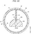
- the pair of second protrusions 40 are in the retaining slit 112 of the pressing portion 50d with the pair of second protrusions 40 in contact with each other, as illustrated in Fig. 22 .
- the second shaft 54 in the distal end direction relative to the first shaft 24, it is possible to prevent the pressing portion 50d and the medical sheet 300 from protruding from the distal-end opening of the outer cylinder 22. Further, the second shaft 54 can be prevented from rotating in the circumferential direction relative to the first shaft 24.
- the retaining slit 112 into which the pair of second protrusions 40 are inserted in the retracted state is formed in the pressing portion 50d.
- Such a configuration allows the pressing portion 50d to hold the support portion 26 in the retracted state. It is therefore possible to prevent, even in a case where the second shaft 54 is pushed by mistake in the distal end direction relative to the first shaft 24, the medical sheet 300 from protruding from the outer cylinder 22.
- the transfer instrument 10 may have a configuration obtained by combining the configurations according to the first modification and the second modification as desired.
- the endoscope 14 may be disposed in the lumen 84 of the outer cylinder 22. Further, the endoscope 14 may be provided separately from the instrument bodies 12, 12a, and 12b. Note that the transfer instrument 10 need not include the endoscope 14.
- the transfer instrument 10 described above may include a lock mechanism that restricts relative movement of the first shafts 24 and 24a and the second shaft 54.
- the lock mechanism can be switched between a locked state where the relative movement of the first shafts 24 and 24a and the second shaft 54 along the axial direction of the first shafts 24 and 24a is restricted and a released state where the restriction is removed.
- the transfer instrument 10 may be used for laparoscopic surgery rather than thoracoscopic surgery. Further, the transfer instrument 10 may be used for thoracotomy or laparotomy.
- the present embodiment discloses a sheet transfer method for transferring, with a transfer instrument, a medical sheet to a treatment site of a living body
- the transfer instrument including a first carrier member including a first shaft and a support portion, the support portion being provided at a distal portion of the first shaft and including a support surface, and a second carrier member including a second shaft and a pressing portion, the second shaft extending along an axial direction of the first shaft, the pressing portion being provided at a distal portion of the second shaft, and in the sheet transfer method, moving the second shaft in a distal end direction relative to the first shaft causes a pressing surface of the pressing portion to press, in the distal end direction, an outer edge surface of the medical sheet placed on the support surface.
Landscapes
- Health & Medical Sciences (AREA)
- Life Sciences & Earth Sciences (AREA)
- Engineering & Computer Science (AREA)
- Heart & Thoracic Surgery (AREA)
- Veterinary Medicine (AREA)
- Public Health (AREA)
- General Health & Medical Sciences (AREA)
- Animal Behavior & Ethology (AREA)
- Biomedical Technology (AREA)
- Surgery (AREA)
- Medical Informatics (AREA)
- Cardiology (AREA)
- Oral & Maxillofacial Surgery (AREA)
- Vascular Medicine (AREA)
- Transplantation (AREA)
- Molecular Biology (AREA)
- Nuclear Medicine, Radiotherapy & Molecular Imaging (AREA)
- Optics & Photonics (AREA)
- Physics & Mathematics (AREA)
- Biophysics (AREA)
- Radiology & Medical Imaging (AREA)
- Pathology (AREA)
- Dermatology (AREA)
- Anesthesiology (AREA)
- Hematology (AREA)
- Media Introduction/Drainage Providing Device (AREA)
Abstract
Description
- The present invention relates to a transfer instrument.
-
JP 2009-511 A - The above-described related art requires that, when transferring the medical sheet from the support portion to the treatment site of the living body, the transfer instrument be manipulated with the upper surface of the medical sheet pressed with forceps or the like, so that there is possibility that the medical sheet cannot be efficiently transferred to the treatment site.
- It is therefore an object of the present invention to solve the above-described problem.
-
- (1) An aspect of the present invention is a transfer instrument that transfers a medical sheet to a treatment site of a living body, the transfer instrument including: a first carrier member including a first shaft and a support portion, the support portion being provided at a distal portion of the first shaft and including a support surface on which the medical sheet is placed; and a second carrier member including a second shaft and a pressing portion, the second shaft extending along an axial direction of the first shaft, the pressing portion being provided at a distal portion of the second shaft, in which the second carrier member is movable relative to the first carrier member so as to allow a pressing surface of the pressing portion to press, in a distal end direction, an outer edge surface of the medical sheet placed on the support surface.
According to the present invention, it is possible to slide, by causing the pressing surface of the pressing portion to press, in the distal end direction, the outer edge surface of the medical sheet placed on the support surface of the first carrier member, the medical sheet from the support surface to the treatment site of the living body. It is therefore possible to efficiently transfer the medical sheet to the treatment site. - (2) In the transfer instrument according to the above (1), the first shaft may be formed in a tubular shape, and the second shaft may be inserted into a lumen of the first shaft so as to be movable along the axial direction of the first shaft.
- (3) In the transfer instrument according to the above (1) or (2), the pressing portion may slide on the support surface when the outer edge surface of the medical sheet is pressed in the distal end direction by the pressing surface.
- (4) In the transfer instrument according to any one of the above (1) to (3), the second carrier member may include a liquid supply flow path through which a liquid is supplied to the medical sheet placed on the support surface.
- (5) In the transfer instrument according to any one of the above (1) to (4), the pressing surface may extend upward with an inclination in the distal end direction.
- (6) In the transfer instrument according to any one of the above (1) to (5), the pressing portion may be formed to be wider in the distal end direction when viewed from above.
- (7) In the transfer instrument according to any one of the above (1) to (4), the pressing surface may be curved in an arc shape in a proximal end direction when viewed from above.
- (8) The transfer instrument according to the above (2) may further include an outer cylinder through which the first shaft is inserted, in which the support portion may be flexible and formed in a sheet shape, the support portion may be formed to be wider than an inner diameter of the outer cylinder, the support portion and the medical sheet may be retracted into the outer cylinder with the support portion and the medical sheet undergoing curved deformation when the first shaft and the second shaft are moved in a proximal end direction relative to the outer cylinder, and the support portion and the medical sheet retracted in the outer cylinder may be unfolded when the first shaft and the second shaft are moved in the distal end direction relative to the outer cylinder to be exposed from the outer cylinder.
- (9) In the transfer instrument according to the above (8), a maximum width of the pressing portion may be smaller than a width of the support portion and larger than an outer diameter of the second shaft.
- (10) In the transfer instrument according to the above (8) or (9), the pressing portion may be flexible, and a width of the pressing surface may be larger than the inner diameter of the outer cylinder.
- (11) In the transfer instrument according to any one of the above (8) to (10), the support portion may include a pair of protrusions protruding upward from both sides of the support surface in a width direction.
- (12) In the transfer instrument according to the above (11), the pressing portion may be provided with a retaining slit into which the pair of protrusions are inserted in a retracted state where the support portion and the medical sheet are retracted in the outer cylinder.
- (13) The transfer instrument according to any one of the above (1) to (12) may further include an endoscope that captures an image of the support portion, the pressing portion, and the medical sheet.
-
-
Fig. 1 is a perspective view of a transfer instrument according to an embodiment of the present invention. -
Fig. 2 is an exploded perspective view of the transfer instrument illustrated inFig. 1 . -
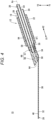
Fig. 3 is a plan view of a distal portion of the transfer instrument illustrated inFig. 1 . -
Fig. 4 is a longitudinal cross-sectional view taken along line IV-IV inFig. 3 . -
Fig. 5 is a transverse cross-sectional view taken along line V-V inFig. 3 . -
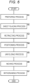
Fig. 6 is a flowchart illustrating a procedure of a transfer method for transferring a medical sheet using the transfer instrument illustrated inFig. 1 . -
Fig. 7 is a first explanatory diagram of a sheet placing process. -
Fig. 8 is a second explanatory diagram of the sheet placing process. -
Fig. 9 is an explanatory diagram of a retracting process. -
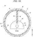
Fig. 10 is a transverse cross-sectional view taken along line X-X inFig. 9 . -
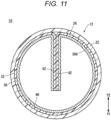
Fig. 11 is a transverse cross-sectional view taken along line XI-XI inFig. 9 . -
Fig. 12 is an explanatory diagram of a positioning process. -
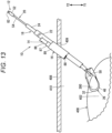
Fig. 13 is an explanatory diagram of an unfolding process. -
Fig. 14 is a first explanatory diagram of a moving process. -
Fig. 15 is a second explanatory diagram of the moving process. -
Fig. 16A is a partially omitted schematic view of a transfer instrument including an instrument body according to a first modification.Fig. 16B is a transverse cross-sectional view taken along line XVIB-XVIB inFig. 16A . -
Fig. 17 is an explanatory diagram of a state where a second carrier member illustrated inFig. 16A is moved in a distal end direction. -
Fig. 18 is a partially omitted perspective view of a second carrier member including a pressing portion according to a first configuration example. -
Fig. 19 is a partially omitted perspective view of a second carrier member including a pressing portion according to a second configuration example. -
Fig. 20 is a partially omitted perspective view of a second carrier member including a pressing portion according to a third configuration example. -
Fig. 21 is a perspective view of a transfer instrument including an instrument body according to a second modification. -
Fig. 22 is a transverse cross-sectional view of the transfer instrument illustrated inFig. 21 , illustrating a state where a support portion is retracted in an outer cylinder. - As illustrated in
Fig. 1 , atransfer instrument 10 according to an embodiment of the present invention is a medical instrument for transferring amedical sheet 300 to a treatment site of a living body. Thetransfer instrument 10 is used for, for example, the treatment of severe heart failure caused by ischemic heart disease. In this case, themedical sheet 300 is transplanted to arecipient site 402 of a heart 400 (the treatment site of the living body) (seeFigs. 12 to 15 ). Thetransfer instrument 10 is capable of attaching a plurality of themedical sheets 300 to therecipient site 402. - Examples of such a
medical sheet 300 include pharmaceutical products or regenerative medicine products for medical use, a medical instrument, and the like. Themedical sheet 300 is formed in a sheet shape such as a film shape or a membrane shape (high viscosity object). Fibrin or the like may be applied to themedical sheet 300 for reinforcement. Examples of the regenerative medicine products including cells include a cell sheet (sheet-shaped cell culture), a spheroid (multicellular spheroid ), and the like. It is possible to form the cell sheet by culturing autologous cells or allogenic cells. The cells constituting the cell sheet include, for example, somatic stem cells (adult stem cells), mesenchymal stem cells, or iPS cells (induced pluripotent stem cells)-derived cardiomyocytes. Examples of the somatic stem cells preferably include skeletal myoblast cells (myoblast cells). - The
medical sheet 300 may contain a tissue adhesive, a local anesthetic, or the like. Themedical sheet 300 has a thickness of, for example, about 100 µm, and has a diameter of, for example, about 60 mm. Note that the thickness and the diameter (size) of themedical sheet 300 can be set as desired. - The
medical sheet 300 may be a sheet to be transplanted to an organ (for example, lung, liver, pancreas, kidney, small intestine, esophagus, or the like) other than theheart 400. Further, themedical sheet 300 may be, for example, an anti-adhesion sheet as long as the sheet is for medical use. - As illustrated in
Figs. 1 and2 , thetransfer instrument 10 includes aninstrument body 12, anendoscope 14, and a fixingmember 16. Theinstrument body 12 includes afirst carrier member 18, asecond carrier member 20, and anouter cylinder 22. - In
Fig. 2 , thefirst carrier member 18 includes afirst shaft 24 and asupport portion 26. Thefirst shaft 24 is a circular tube member having afirst lumen 28. Thefirst lumen 28 opens at a distal end (end in a direction of arrow X1) of thefirst shaft 24 and opens at a proximal end (end in a direction of arrow X2) of thefirst shaft 24. - The
first shaft 24 includes, for example, a resin material. Examples of the constituent material of thefirst shaft 24 include, but not particularly limited to, polyethylene, polypropylene, fluororesin, polyethylene terephthalate, polymethyl methacrylate, polyamide resin, polystyrene, polycarbonate, polyimide, polyetherimide, polyetheretherketone, polyvinyl chloride, and ABS resin. Thefirst shaft 24 may include a metal material. - The
first shaft 24 may be flexible. Thefirst shaft 24 may include a flexible tube portion capable of retaining a bent shape. In this case, thefirst shaft 24 can be bent into an any desired shape in a body cavity and can retaining the bent shape. The flexible tube portion is formed by, for example, forming a tube wall portion in a pleated shape. Note that the flexible tube portion may include a material capable of retaining a bent shape. Specifically, the flexible tube portion can be formed, for example, by inserting a linear metal member capable of retaining a bent shape into the lumen of thefirst shaft 24 including resin. The flexible tube portion forms only a part of thefirst shaft 24 in a longitudinal direction. Note that the flexible tube portion may form the entirefirst shaft 24. - As illustrated in
Figs. 2 to 4 , thesupport portion 26 is attached to a distal portion of thefirst shaft 24. Thesupport portion 26 includes, for example, a resin material. The constituent material of thesupport portion 26 preferably has transparency, and examples of the constituent material include, but not particularly limited to, polycarbonate, polyamide, polystyrene, polypropylene, polyacetal resin, polyimide, polyetheretherketone, polyethylene terephthalate, and fluororesin. - The
support portion 26 is flexible. A resin sheet member (film member) is bent into a predetermined form to form thesupport portion 26. Alternatively, the sheet member is shaped into a predetermined form by a sheet forming die to form thesupport portion 26. It is preferable that the sheet member have, but not particularly limited to, a thickness of, for example, 100 µm or more and 200 µm or less. Thesupport portion 26 includes a joint 30 and asupport body 32. - In
Fig. 4 , the joint 30 is bonded to an inner peripheral surface of the distal portion of thefirst shaft 24 with an adhesive. Examples of the adhesive include, but not particularly limited to, a UV adhesive and an instant adhesive (for example, cyanoacrylate-based instant adhesive). The joint 30 may be thermally fused to the inner peripheral surface of thefirst shaft 24. In a case where the joint 30 is joined to the inner peripheral surface of the distal portion of thefirst shaft 24, the joint 30 does not form a step on an outer peripheral surface of thefirst shaft 24, so that thefirst shaft 24 can be smoothly inserted into theouter cylinder 22. The joint 30 may be joined to a lower surface (an outer surface facing the direction of arrow Y1) of the distal portion of thefirst shaft 24. - As illustrated in
Fig. 3 , thesupport body 32 extends in a distal end direction from the joint 30 (seeFig. 4 ). Thesupport body 32 includes a proximal-end support portion 34, a pair offirst protrusions 36, anintermediate support portion 38, a pair ofsecond protrusions 40, a pair ofthird protrusions 42, and a distal-end support portion 44. - The proximal-
end support portion 34 extends roughly along an axis Ax of thefirst shaft 24 from a distal end of the joint 30 in the distal end direction (seeFig. 4 ). The proximal-end support portion 34 is formed to be wider in its extending direction. In other words, both sides of the proximal-end support portion 34 in a width direction are tapered toward the joint 30. - In
Figs. 2 and3 , the pair offirst protrusions 36 protrude upward (in a direction of arrow Y2) from both the sides of the proximal-end support portion 34. Theintermediate support portion 38 extends from a distal end of the proximal-end support portion 34 in the distal end direction at an angle relative to the proximal-end support portion 34 so as to approach the axis Ax of the first shaft 24 (seeFig. 4 ). Theintermediate support portion 38 is formed with a substantially constant width over the entire length. Note that theintermediate support portion 38 may be formed to be wider or narrower in the distal end direction. - The pair of
second protrusions 40 are connected to distal ends of the pair offirst protrusions 36. The pair ofsecond protrusions 40 protrude upward from both sides of theintermediate support portion 38 in the width direction and inward in the width direction of theintermediate support portion 38. The pair ofthird protrusions 42 are connected to distal ends of the pair ofsecond protrusions 40. The pair ofthird protrusions 42 protrude upward from both the sides of theintermediate support portion 38 in the width direction and outward in the width direction of theintermediate support portion 38. - The distal-
end support portion 44 is connected to a distal end of theintermediate support portion 38 and distal ends of the pair ofthird protrusions 42. The distal-end support portion 44 protrudes in an arc shape in the distal end direction. In other words, the distal-end support portion 44 is formed to be narrower in the distal end direction. - The
support body 32 includes asupport surface 46 facing upward. Specifically, thesupport surface 46 is formed by an upper surface of theintermediate support portion 38, an upper surface of the distal-end support portion 44, and upper surfaces of the pair ofthird protrusions 42. A lubricant may be applied to thesupport surface 46 so as to allow a pressing portion 50 (to be described later) of thesecond carrier member 20 to smoothly slide on thesupport surface 46. - A part of the
support surface 46 formed by the upper surface of theintermediate support portion 38 and the upper surface of the distal-end support portion 44 is a flat surface (seeFig. 4 ). Note that the part of thesupport surface 46 formed by the upper surface of theintermediate support portion 38 and the upper surface of the distal-end support portion 44 may be a curved surface that curves in a direction opposite to the direction that thesupport surface 46 faces. - As illustrated in
Fig. 2 , thesecond carrier member 20 includes asecond shaft 54, thepressing portion 50, and aconnector 52. Thesecond shaft 54 is a circular tube member having asecond lumen 57. Thesecond lumen 57 opens at a distal end (end in the direction of arrow X1) of thesecond shaft 54 and opens at a proximal end (end in the direction of arrow X2) of thesecond shaft 54. - The
second shaft 54 is longer in the axial direction than thefirst shaft 24. Thesecond shaft 54 is inserted into thefirst lumen 28 of the first shaft 24 (seeFigs. 1 and4 ). In other words, a distal portion of thesecond shaft 54 protrudes in the distal end direction relative to a distal-end opening of thefirst shaft 24. A proximal portion of thesecond shaft 54 protrudes in the proximal end direction relative to a proximal-end opening of the first shaft 24 (seeFig. 1 ). - The
second shaft 54 is configured to follow the shape (angle) of thesupport portion 26. As the constituent material of thesecond shaft 54, for example, a material more flexible than the constituent material of thefirst shaft 24 is selected. Specifically, examples of the constituent material of thesecond shaft 54 include a polyamide elastomer, a polyester elastomer, a polyurethane elastomer, polyvinyl chloride, polybutadiene, a silicone rubber, and a metal coil (including a composite with a resin). Thesecond shaft 54 is flexible. Note that in a case where thefirst shaft 24 includes the flexible tube portion, thesecond shaft 54 bends along the bent shape of thefirst shaft 24. Thepressing portion 50 is attached to the distal portion of thesecond shaft 54. - As illustrated in
Fig. 4 , aninsertion hole 58, apressing surface 64, and asupply hole 66 are formed in thepressing portion 50. The distal portion of thesecond shaft 54 is inserted into theinsertion hole 58. The distal portion of thesecond shaft 54 is thermally fused to an inner surface forming theinsertion hole 58. Note that the distal portion of thesecond shaft 54 may be joined to the inner surface forming theinsertion hole 58 with an adhesive. InFig. 3 , thepressing portion 50 is formed to be wider in the distal end direction when viewed from above. Thepressing portion 50 is formed in a trapezoidal shape when viewed from above. - In
Fig. 4 , thepressing surface 64 is provided on a distal end surface of thepressing portion 50. Thepressing surface 64 presses an outer edge surface 302 (seeFig. 14 ) of themedical sheet 300 in the distal end direction. Thepressing surface 64 extends upward with an inclination in the distal end direction (the direction of arrow X1). Thepressing surface 64 includes a flat surface. - As illustrated in
Figs. 4 and5 , thesupply hole 66 communicates with thesecond lumen 57 of thesecond shaft 54 and opens to thepressing surface 64. Thesupply hole 66 and thesecond lumen 57 communicate with each other to form a liquidsupply flow path 68. The liquidsupply flow path 68 guides, toward a distal end of thepressing portion 50, a liquid for preventing themedical sheet 300 from drying out. As the liquid, for example, a physiological saline solution is used. - In
Fig. 2 , theconnector 52 is attached to the proximal portion of thesecond shaft 54. Theconnector 52 is configured as a so-called straight connector. Theconnector 52 includes aconnection port 82 to which a liquid supply instrument (not illustrated) is detachably attached. - In
Figs. 1 and2 , theouter cylinder 22 is a cylindrical member having alumen 84. Thelumen 84 opens at a distal end (end in the direction of arrow X1) of theouter cylinder 22 and opens at a proximal end (end in the direction of arrow X2) of theouter cylinder 22. Theouter cylinder 22 is flexible. Examples of the constituent material of theouter cylinder 22 are the same as the examples of the constituent material of thefirst shaft 24 described above. Note that in a case where thefirst shaft 24 includes the flexible tube portion, theouter cylinder 22 bends along the bent shape of thefirst shaft 24. Further, in the present embodiment, theouter cylinder 22 may include the flexible tube portion as described above. In this case, thefirst shaft 24 need not include the flexible tube portion. - The
first shaft 24 is inserted into thelumen 84 of theouter cylinder 22. Theouter cylinder 22 is shorter in the axial direction than thefirst shaft 24. InFigs. 3 and4 , an inner diameter D1 of theouter cylinder 22 is smaller than the width W1 of theintermediate support portion 38. The width W1 of theintermediate support portion 38 is substantially identical to a circumferential length of an inner surface of theouter cylinder 22 so as to allow thesupport portion 26 to be retracted into theouter cylinder 22 with thesupport portion 26 curled into a cylinder along a circumferential direction of an inner peripheral surface of theouter cylinder 22. Note that the width W1 may be shorter or longer than the circumferential length of the inner surface of theouter cylinder 22 as long as thesupport portion 26 can be retracted into theouter cylinder 22. A maximum width W2 of thepressing portion 50 is smaller than an inner diameter D1 of theouter cylinder 22 and larger than an outer diameter of thesecond shaft 54. It is therefore possible to make thepressing portion 50 relatively wide and retract thepressing portion 50 into theouter cylinder 22 with ease. The maximum width W2 of thepressing portion 50 is smaller than the width W1 of theintermediate support portion 38 and larger than the outer diameter of thesecond shaft 54. - In
Figs. 2 and4 , a distal end surface of theouter cylinder 22 extends in a direction orthogonal to the axial direction of theouter cylinder 22. Note that the distal end surface of theouter cylinder 22 may extend upward with an inclination in the proximal end direction. In this case, for example, in thoracoscopic surgery, theouter cylinder 22 is easily inserted into an incision 409 (Fig. 12 ) of achest 408. Further, the angle of the distal end surface of theouter cylinder 22 serves as a guide for a surgeon to recognize the upper surface of thesupport portion 26. - As illustrated in
Figs. 1 and2 , theendoscope 14 includes a long endoscopemain body 86. A distal portion of the endoscopemain body 86 is fixed to an outer peripheral surface of theouter cylinder 22 by the fixingmember 16. Anobjective lens 88 provided on a distal end surface of the endoscopemain body 86 is oriented toward the distal end of the outer cylinder 22 (in the direction of arrow X1). The distal portion of the endoscopemain body 86 is fixed to an intermediate portion of theouter cylinder 22 in the axial direction. Note that the distal portion of the endoscopemain body 86 may be fixed to a distal portion of theouter cylinder 22. - The fixing
member 16 includes, for example, a fixingcylinder 87 and a fixingtube 89. The fixingcylinder 87 includes, for example, a hard resin material. The endoscopemain body 86 can be inserted into a lumen of the fixingcylinder 87. The fixingcylinder 87 is disposed along a longitudinal direction of theouter cylinder 22. The fixingtube 89 is a tube for fixing the fixingcylinder 87 at a predetermined position of theouter cylinder 22. The fixingtube 89 is, for example, a heat-shrinkable tube. Note that theouter cylinder 22 and the fixingcylinder 87 may be integrally molded. Note that how to fix the distal portion of the endoscopemain body 86 to theouter cylinder 22 may be determined as desired. - Next, a transfer method for transferring the
medical sheet 300 to a treatment site of a living body will be described. Specifically, as illustrated inFigs. 12 to 15 , the transfer method for transferring themedical sheet 300 to therecipient site 402 of the heart 400 (the treatment site of the living body) during thoracoscopic surgery will be described. As illustrated inFig. 6 , the transfer method according to the present embodiment includes a preparing process, a sheet placing process, a retracting process, a positioning process, an unfolding process, a moving process, and a withdrawing process. - First, in the preparing process (step S1), the
transfer instrument 10 according to the present embodiment described above is prepared. Thetransfer instrument 10 is brought into an initial state as illustrated inFig. 1 . That is, thesupport portion 26 protrudes in the distal end direction from a distal-end opening of theouter cylinder 22. At this time, thepressing portion 50 is positioned on thesupport surface 46. Further, a proximal portion of thepressing portion 50 is in thefirst lumen 28 of thefirst shaft 24. - Next, in the sheet placing process (step S2), as illustrated in
Figs. 7 and8 , themedical sheet 300 cultured in aPetri dish 401 is placed on thesupport surface 46. The pair ofsecond protrusions 40 prevent themedical sheet 300 from moving (becoming misaligned) in the width direction of theintermediate support portion 38 with themedical sheet 300 placed on thesupport surface 46. - Subsequently, in the retracting process (step S3 in
Fig. 6 ), themedical sheet 300 is retracted into theouter cylinder 22 together with thesupport portion 26. Specifically, thefirst shaft 24 of thefirst carrier member 18 and thesecond shaft 54 of thesecond carrier member 20 are moved together in the proximal end direction relative to theouter cylinder 22. - Accordingly, the proximal-
end support portion 34 is pulled in the proximal end direction through the distal-end opening of theouter cylinder 22. At this time, when both the tapered sides of the proximal-end support portion 34 come into contact with the distal end surface of theouter cylinder 22, a force acts on the proximal-end support portion 34 to cause the proximal-end support portion 34 to curl along the circumferential direction of theouter cylinder 22. Therefore, the proximal-end support portion 34 is smoothly pulled into theouter cylinder 22 while curling. - When the proximal-
end support portion 34 becomes deformed, a force acts on theintermediate support portion 38 to cause theintermediate support portion 38 to curl along the circumferential direction of theouter cylinder 22, so that theintermediate support portion 38 is pulled into theouter cylinder 22 while curling. At this time, since the width W1 of theintermediate support portion 38 is substantially identical to the circumferential length of the inner surface of theouter cylinder 22, theintermediate support portion 38 is deformed into a cylindrical shape along the inner surface of theouter cylinder 22. Themedical sheet 300 is inserted into theouter cylinder 22 with themedical sheet 300 deformed into a shape corresponding to the shape of thesupport body 32. As illustrated inFig. 9 , when thesupport portion 26 is entirely inserted into theouter cylinder 22, the retracting process is complete. - In a retracted state where the
support portion 26 and themedical sheet 300 are retracted in theouter cylinder 22, as illustrated inFig. 10 , the pair ofsecond protrusions 40 are positioned in the distal end direction relative to thepressing surface 64 of thepressing portion 50 with the pair ofsecond protrusions 40 in contact with each other. This restricts the movement of thesecond carrier member 20 in the distal end direction relative to thefirst carrier member 18. That is, the movement of thesecond shaft 54 in the distal end direction relative to thefirst shaft 24 is restricted. Therefore, even in a case where the user pushes by mistake thesecond shaft 54 in the distal end direction relative to thefirst shaft 24, it is possible to prevent themedical sheet 300 from protruding from the distal-end opening of theouter cylinder 22. Further, thesecond shaft 54 can be prevented from rotating in the circumferential direction relative to thefirst shaft 24. - In the retracted state, as illustrated in
Fig. 11 , the pair ofthird protrusions 42 extend downward (in the direction of arrow Y1) from an upper end of theouter cylinder 22 with the pair ofthird protrusions 42 in contact with each other. Protruding end surfaces of the pair ofthird protrusions 42 are separated from themedical sheet 300. Themedical sheet 300 is deformed along the shape of thesupport portion 26. That is, this prevents themedical sheet 300 from being folded over in theouter cylinder 22. - Subsequently, in the positioning process (step S4 in
Fig. 6 ), as illustrated inFig. 12 , thetransfer instrument 10 is inserted into achest cavity 410 through theincision 409 of thechest 408. At this time, the distal end of thetransfer instrument 10 is positioned near therecipient site 402 of theheart 400, and the distal end of theendoscope 14 is positioned in thechest cavity 410. Note that before thetransfer instrument 10 is inserted into thechest cavity 410, a liquid supply instrument (not illustrated) may be connected to theconnection port 82 of theconnector 52 to introduce a liquid (for example, a physiological saline solution). The liquid introduced from theconnection port 82 is guided to themedical sheet 300 through the liquid supply flow path 68 (thesecond lumen 57 and the supply hole 66). This makes it possible to prevent themedical sheet 300 from drying out. - Subsequently, in the unfolding process (step S5 in
Fig. 6 ), as illustrated inFig. 13 , thesupport portion 26 and themedical sheet 300 are unfolded. Specifically, in the unfolding process, thefirst shaft 24 and thesecond shaft 54 are moved in the distal end direction relative to theouter cylinder 22. Accordingly, thesupport portion 26 that has moved out of the distal-end opening of theouter cylinder 22 returns to the original shape due to its restoring force. When thesupport portion 26 is unfolded, themedical sheet 300 unrolls flat. - Next, in the moving process (step S6 in
Fig. 6 ), as illustrated inFigs. 14 and15 , moving thesecond shaft 54 in the distal end direction relative to thefirst shaft 24 causes thepressing surface 64 to press, in the distal end direction, a part facing the proximal end direction of theouter edge surface 302 of themedical sheet 300 placed on thesupport surface 46. At this time, thepressing portion 50 slides on thesupport surface 46 in the distal end direction. Themedical sheet 300 pressed by thepressing portion 50 slides on thesupport surface 46 in the distal end direction while maintaining its original shape. It is therefore possible to move themedical sheet 300 smoothly from thesupport surface 46 to therecipient site 402 of theheart 400. - Subsequently, in the withdrawing process (step S7 in
Fig. 6 ), thetransfer instrument 10 is withdrawn from thechest 408 with thesupport portion 26 and thepressing portion 50 retracted in theouter cylinder 22. - The
transfer instrument 10 according to the present embodiment has the following effects. - According to the present embodiment, it is possible to slide, by causing the
pressing surface 64 of thepressing portion 50 to press, in the distal end direction, theouter edge surface 302 of themedical sheet 300 placed on thesupport surface 46 of thefirst carrier member 18, themedical sheet 300 from thesupport surface 46 to therecipient site 402 of theheart 400. It is therefore possible to efficiently transfer themedical sheet 300 to therecipient site 402. - The
first shaft 24 is formed in a tubular shape. Thesecond shaft 54 is inserted into thefirst lumen 28 of thefirst shaft 24 with thesecond shaft 54 movable along the axial direction of thefirst shaft 24. - Such a configuration can make the
transfer instrument 10 compact as compared with a configuration where thesecond shaft 54 is disposed outside thefirst shaft 24. - The
pressing portion 50 slides on thesupport surface 46 when theouter edge surface 302 of themedical sheet 300 is pressed in the distal end direction by thepressing surface 64. - Such a configuration allows the
pressing surface 64 to efficiently press theouter edge surface 302 of themedical sheet 300 placed on thesupport surface 46. - The
second carrier member 20 includes the liquidsupply flow path 68 through which a liquid is supplied to themedical sheet 300 placed on thesupport surface 46. - Such a configuration allows a liquid to be supplied to the
medical sheet 300 through the liquidsupply flow path 68, so that it is possible to prevent themedical sheet 300 from drying out. - The
pressing surface 64 extends upward with an inclination in the distal end direction. - Such a configuration can prevent the
medical sheet 300 from running on to thepressing surface 64. - The
pressing portion 50 is formed to be wider in the distal end direction when viewed from above. - Such a configuration allows an increase in the area of the
pressing surface 64 with ease. - The
transfer instrument 10 includes theouter cylinder 22 through which thefirst shaft 24 is inserted. Thesupport portion 26 is flexible and formed in a sheet shape. Thesupport portion 26 is formed to be wider than the inner diameter D1 of theouter cylinder 22. When thefirst shaft 24 and thesecond shaft 54 are moved in the proximal end direction relative to theouter cylinder 22, thesupport portion 26 and themedical sheet 300 are retracted into theouter cylinder 22 with thesupport portion 26 and themedical sheet 300 undergoing curved deformation along the circumferential direction of theouter cylinder 22. Thesupport portion 26 and themedical sheet 300 retracted in theouter cylinder 22 are unfolded when thefirst shaft 24 and thesecond shaft 54 are moved in the distal end direction relative to theouter cylinder 22 to be exposed from theouter cylinder 22. - Such a configuration allows, in thoracoscopic surgery (body cavity surgery), the
outer cylinder 22 to be inserted into the chest cavity 410 (body cavity) from theincision 409 of thechest 408 with thesupport portion 26 and themedical sheet 300 retracted in theouter cylinder 22. Note that the body cavity includes thechest cavity 410 and the abdominal cavity. Further, in thechest cavity 410, when thesupport portion 26 in the retracted state is exposed from theouter cylinder 22, thesupport portion 26 and themedical sheet 300 can be unfolded. It is therefore possible to make a small incision in thechest 408 of the patient and transfer themedical sheet 300 to therecipient site 402 through the small incision, so that it is possible to achieve low invasion as compared with thoracotomy. Furthermore, in thoracoscopic surgery, themedical sheet 300 having a diameter larger than the inner diameter D1 of theouter cylinder 22 can be positioned adjacent to the recipient site 402 (the treatment site of the living body) of theheart 400. - The maximum width W2 of the
pressing portion 50 is smaller than the width of the support portion 26 (the width W1 of the intermediate support portion 38) and larger than the outer diameter of thesecond shaft 54. - Such a configuration can make the
pressing surface 64 relatively wide. - The
support portion 26 includes the pair ofsecond protrusions 40 protruding upward from both sides of thesupport surface 46 in the width direction. - Such a configuration allows the pair of
second protrusions 40 to prevent themedical sheet 300 from falling outside of thesupport body 32. - The
transfer instrument 10 further includes theendoscope 14 that captures an image of thesupport portion 26, thepressing portion 50, and themedical sheet 300. - Such a configuration makes it possible to check, with the
endoscope 14, how themedical sheet 300 is transferred to therecipient site 402. - As illustrated in
Figs. 16A and 16B , thetransfer instrument 10 may include aninstrument body 12a according to a first modification. Note that, in the present modification, the same components as those of the above-describedinstrument body 12 are denoted by the same reference numerals, and the detailed description of the same components will be omitted. The same applies to aninstrument body 12b according to a second modification to be described later. Theinstrument body 12a includes afirst carrier member 18a, asecond carrier member 20a, and theouter cylinder 22. - The
first carrier member 18a includes afirst shaft 24a and the support portion 26 (seeFig. 2 ). An insertion slit 100 is formed in a proximal portion of thefirst shaft 24a. The insertion slit 100 communicates with afirst lumen 28 of thefirst shaft 24a. In other words, the insertion slit 100 extends through a peripheral wall of thefirst shaft 24a in the radial direction. The insertion slit 100 extends along the axial direction of theouter cylinder 22. A width W3 of the insertion slit 100 is smaller than an outer diameter D2 of thesecond shaft 54 to be described later (seeFig. 16B ). - The
second carrier member 20a includes thesecond shaft 54 and aconnector 52a. The proximal end of thesecond shaft 54 is sealed so as to prevent thesecond lumen 57 from communicating with the outside. Theconnector 52a extends through the insertion slit 100 and extends radially outward from the proximal portion of thesecond shaft 54. Theconnector 52a includes aconnection port 82a exposed to the outside of thefirst shaft 24a. - As illustrated in
Fig. 17 , such a configuration causes theconnector 52a to move through the insertion slit 100 in the distal end direction when thesecond carrier member 20a is moved in the distal end direction. In this case, the overall length of thetransfer instrument 10 can be shortened. - As illustrated in
Fig. 18 , thesecond carrier member 20 may include apressing portion 50a according to a first configuration example instead of thepressing portion 50 described above. - The
pressing portion 50a is formed to be wider in the distal end direction. Specifically, thepressing portion 50a extends outward in the width direction while extending in the distal end direction. Both side surfaces 51 in the width direction of thepressing portion 50a are flat surfaces tapered in the proximal end direction (toward the second shaft 54). Note that each of the side surfaces 51 may be a curved surface curved in an arc shape outward in the width direction. Bothend portions 53 on the outer sides in the width direction of thepressing portion 50a are curved in an arc shape (semicircular shape) when viewed from above. Thepressing portion 50a is formed symmetrically about the axis of thesecond shaft 54. A distal portion of thepressing portion 50a is provided with apressing surface 64a facing the distal end direction. - The
pressing surface 64a is curved in an arc shape in the proximal end direction when viewed from above. In other words, thepressing surface 64a is curved in an arc shape in the proximal end direction to follow the shape of the outer periphery of themedical sheet 300. Thepressing surface 64a extends upward with an inclination in the distal end direction. That is, thepressing surface 64a is at an angle relative to a plane orthogonal to the axis of thesecond shaft 54. - A maximum width W4 of the
pressing portion 50a (a width of the distal end of thepressing portion 50a) is larger than the inner diameter D1 of the outer cylinder 22 (seeFig. 4 ). Thepressing portion 50a has flexibility so as to be retractable into theouter cylinder 22. Thepressing portion 50a includes a soft resin material. The maximum width W4 of thepressing portion 50a is smaller than the width W1 of theintermediate support portion 38 and larger than the outer diameter of thesecond shaft 54. On thepressing surface 64a, thesupply hole 66 through which a liquid is supplied from thepressing portion 50a in the distal end direction opens. - The
pressing portion 50a according to the present configuration example produces the same effect as the effect produced by thepressing portion 50 described above. That is, the maximum width W4 of thepressing portion 50a is smaller than the width of the support portion 26 (the width W1 of the intermediate support portion 38) and larger than the outer diameter of thesecond shaft 54. It is therefore possible to make thepressing surface 64a relatively wide. - The
pressing portion 50a is formed to be wider in the distal end direction when viewed from above. - Such a configuration can make the
pressing surface 64a wider. - The
pressing surface 64a is curved in an arc shape in the proximal end direction when viewed from above. - Such a configuration allows, for example, even in a case where the
medical sheet 300 is formed in a circular shape, thepressing surface 64a to reliably press theouter edge surface 302 of themedical sheet 300. - The
pressing portion 50a is flexible. The maximum width W4 (the width of thepressing surface 64a) of thepressing portion 50a is larger than the inner diameter D1 of theouter cylinder 22. - Such a configuration can make the
pressing surface 64a wider with thepressing portion 50a retractable into theouter cylinder 22. - In the present configuration example, the
pressing portion 50a may include a hard resin material. In this case, the maximum width W4 of thepressing portion 50a is smaller than the inner diameter D1 of theouter cylinder 22 so as to make thepressing portion 50a retractable into theouter cylinder 22. Further, thepressing portion 50a may be integrally molded with thesecond shaft 54. Thesupply hole 66 need not be formed in thepressing portion 50a. - As illustrated in
Fig. 19 , thesecond carrier member 20 may include apressing portion 50b according to a second configuration example instead of thepressing portion 50 described above. - The
pressing portion 50b includes aconnection portion 90 and apressing body 92. Theconnection portion 90 has the same configuration as the configuration of thepressing portion 50 described above. That is, theconnection portion 90 is formed to be wider in the distal end direction. Thepressing body 92 is attached to a flat distal end surface of theconnection portion 90. Thepressing body 92 is a flat plate portion extending in one direction. Thepressing body 92 includes apressing surface 64b facing the distal end direction. - The
pressing surface 64b extends upward with an inclination in the distal end direction. That is, thepressing surface 64b is at an angle relative to a plane orthogonal to the axis of thesecond shaft 54. Thepressing surface 64b is a flat surface extending along a direction (width direction) orthogonal to the axis of thesecond shaft 54. A maximum width W5 of thepressing portion 50b (a width of a distal end of thepressing portion 50b) is larger than the inner diameter D1 of the outer cylinder 22 (seeFig. 4 ). Thepressing portion 50b has flexibility so as to be retractable into theouter cylinder 22. Thepressing portion 50b includes a soft resin material. On thepressing surface 64b, thesupply hole 66 through which a liquid is supplied from thepressing portion 50b in the distal end direction opens. - The
pressing portion 50b according to the present configuration example produces the same effect as the effect produced by thepressing portion 50 described above. - The
pressing portion 50b is flexible. The maximum width W5 of thepressing portion 50b is larger than the inner diameter D1 of theouter cylinder 22. - Such a configuration can make the
pressing surface 64b wider with thepressing portion 50b retractable into theouter cylinder 22. - In the present configuration example, the
pressing portion 50b may include a hard resin material. In this case, the maximum width W5 of thepressing portion 50b is smaller than the inner diameter D1 of theouter cylinder 22 so as to make thepressing portion 50b retractable into theouter cylinder 22. Further, thepressing portion 50b may be integrally molded with thesecond shaft 54. Thesupply hole 66 need not be formed in thepressing portion 50b. - As illustrated in
Fig. 20 , thesecond carrier member 20 may include apressing portion 50c according to a third configuration example instead of thepressing portion 50 described above. - The
pressing portion 50c is a plate-shaped portion attached to the outer peripheral surface of the distal portion of thesecond shaft 54. Specifically, thepressing portion 50c is thermally fused to thesecond shaft 54. Note that thepressing portion 50c may be joined to thesecond shaft 54 with an adhesive or the like. - The
pressing portion 50c protrudes in the distal end direction relative to the distal end of thesecond shaft 54. A distal portion of thepressing portion 50c is provided with apressing surface 64c facing the distal end direction. Thepressing surface 64c is a flat surface. A maximum width W6 of thepressing portion 50c (a width of a distal end of thepressing portion 50c) is smaller than the inner diameter D1 of the outer cylinder 22 (seeFig. 4 ). The maximum width W6 is larger than the outer diameter of thesecond shaft 54. Thepressing portion 50c includes a hard resin material. Note that thepressing portion 50c may include a soft resin material. The distal end of the second shaft 54 (the distal-end opening of the second lumen 57) is positioned above thepressing portion 50c. - In the present configuration example, the
pressing portion 50c does not include thesupply hole 66 described above. A liquid guided from the second lumen 57 (liquid supply flow path 68) of thesecond shaft 54 flows on the upper surface of thepressing portion 50c and is supplied to themedical sheet 300 positioned in the distal end relative to thepressing surface 64c. - The
pressing portion 50c according to the present configuration example produces the same effect as the effect produced by thepressing portion 50c described above. - In the present configuration example, since the plate-shaped
pressing portion 50c is attached to the outer peripheral surface of the distal portion of thesecond shaft 54, the configuration of thesecond shaft 54 can be made simple. - As illustrated in
Figs. 21 and22 , thetransfer instrument 10 may include theinstrument body 12b according to the second modification. Theinstrument body 12b includes thefirst carrier member 18, asecond carrier member 20b, and theouter cylinder 22. - The
second carrier member 20b includes thesecond shaft 54, apressing portion 50d, and theconnector 52. A retainingslit 112 is formed in an upper surface of thepressing portion 50d. The retaining slit 112 extends over the entire length of thepressing portion 50d. The retaining slit 112 opens upward. - In the present modification, in the retracted state where the
support portion 26, thepressing portion 50d, and themedical sheet 300 are retracted in theouter cylinder 22, the pair ofsecond protrusions 40 are in the retaining slit 112 of thepressing portion 50d with the pair ofsecond protrusions 40 in contact with each other, as illustrated inFig. 22 . This restricts the movement of thesecond carrier member 20b relative to thefirst carrier member 18. That is, the movement of thesecond shaft 54 along the axial direction relative to thefirst shaft 24 is restricted. Therefore, even in a case where the user presses, by mistake, thesecond shaft 54 in the distal end direction relative to thefirst shaft 24, it is possible to prevent thepressing portion 50d and themedical sheet 300 from protruding from the distal-end opening of theouter cylinder 22. Further, thesecond shaft 54 can be prevented from rotating in the circumferential direction relative to thefirst shaft 24. - The retaining slit 112 into which the pair of
second protrusions 40 are inserted in the retracted state is formed in thepressing portion 50d. - Such a configuration allows the
pressing portion 50d to hold thesupport portion 26 in the retracted state. It is therefore possible to prevent, even in a case where thesecond shaft 54 is pushed by mistake in the distal end direction relative to thefirst shaft 24, themedical sheet 300 from protruding from theouter cylinder 22. - The
transfer instrument 10 according to the present embodiment may have a configuration obtained by combining the configurations according to the first modification and the second modification as desired. Theendoscope 14 may be disposed in thelumen 84 of theouter cylinder 22. Further, theendoscope 14 may be provided separately from theinstrument bodies transfer instrument 10 need not include theendoscope 14. - The
transfer instrument 10 described above may include a lock mechanism that restricts relative movement of thefirst shafts second shaft 54. The lock mechanism can be switched between a locked state where the relative movement of thefirst shafts second shaft 54 along the axial direction of thefirst shafts first shafts second shaft 54 together relative to theouter cylinder 22 in the retracting process and the positioning process. That is, it is possible to prevent an erroneous operation of moving thesecond shaft 54 relative to thefirst shafts - The
transfer instrument 10 may be used for laparoscopic surgery rather than thoracoscopic surgery. Further, thetransfer instrument 10 may be used for thoracotomy or laparotomy. - The present embodiment discloses a sheet transfer method for transferring, with a transfer instrument, a medical sheet to a treatment site of a living body, the transfer instrument including a first carrier member including a first shaft and a support portion, the support portion being provided at a distal portion of the first shaft and including a support surface, and a second carrier member including a second shaft and a pressing portion, the second shaft extending along an axial direction of the first shaft, the pressing portion being provided at a distal portion of the second shaft, and in the sheet transfer method, moving the second shaft in a distal end direction relative to the first shaft causes a pressing surface of the pressing portion to press, in the distal end direction, an outer edge surface of the medical sheet placed on the support surface.
- Note that the present invention is not limited to the disclosure, and various configurations can be adopted without departing from the gist of the present invention.
Claims (13)
- A transfer instrument that transfers a medical sheet to a treatment site of a living body, the transfer instrument comprising:a first carrier member including a first shaft and a support portion, the support portion being provided at a distal portion of the first shaft and including a support surface on which the medical sheet is placed; anda second carrier member including a second shaft and a pressing portion, the second shaft extending along an axial direction of the first shaft, the pressing portion being provided at a distal portion of the second shaft, whereinthe second carrier member is movable relative to the first carrier member so as to allow a pressing surface of the pressing portion to press, in a distal end direction, an outer edge surface of the medical sheet placed on the support surface.
- The transfer instrument according to claim 1, whereinthe first shaft is formed in a tubular shape, andthe second shaft is inserted into a lumen of the first shaft so as to be movable along the axial direction of the first shaft.
- The transfer instrument according to claim 1, wherein
the pressing portion slides on the support surface when the outer edge surface of the medical sheet is pressed in the distal end direction by the pressing surface. - The transfer instrument according to claim 1, wherein
the second carrier member includes a liquid supply flow path through which a liquid is supplied to the medical sheet placed on the support surface. - The transfer instrument according to claim 1, wherein
the pressing surface extends upward with an inclination in the distal end direction. - The transfer instrument according to claim 1, wherein
the pressing portion is formed to be wider in the distal end direction when viewed from above. - The transfer instrument according to claim 1, wherein
the pressing surface is curved in an arc shape in a proximal end direction when viewed from above. - The transfer instrument according to claim 2, further comprisingan outer cylinder through which the first shaft is inserted, whereinthe support portion is flexible and formed in a sheet shape,the support portion is formed to be wider than an inner diameter of the outer cylinder,the support portion and the medical sheet are retracted into the outer cylinder with the support portion and the medical sheet undergoing curved deformation when the first shaft and the second shaft are moved in a proximal end direction relative to the outer cylinder, andthe support portion and the medical sheet retracted in the outer cylinder are unfolded when the first shaft and the second shaft are moved in the distal end direction relative to the outer cylinder to be exposed from the outer cylinder.
- The transfer instrument according to claim 8, wherein
a maximum width of the pressing portion is smaller than a width of the support portion and larger than an outer diameter of the second shaft. - The transfer instrument according to claim 8, whereinthe pressing portion is flexible, anda width of the pressing surface is larger than the inner diameter of the outer cylinder.
- The transfer instrument according to claim 8, wherein
the support portion includes a pair of protrusions protruding upward from both sides of the support surface in a width direction. - The transfer instrument according to claim 11, wherein
the pressing portion is provided with a retaining slit into which the pair of protrusions are inserted in a retracted state where the support portion and the medical sheet are retracted in the outer cylinder. - The transfer instrument according to any one of claims 1 to 12, further comprising
an endoscope that captures an image of the support portion, the pressing portion, and the medical sheet.
Applications Claiming Priority (2)
| Application Number | Priority Date | Filing Date | Title |
|---|---|---|---|
| JP2022089711 | 2022-06-01 | ||
| PCT/JP2023/020397 WO2023234381A1 (en) | 2022-06-01 | 2023-06-01 | Transfer instrument |
Publications (2)
| Publication Number | Publication Date |
|---|---|
| EP4520382A1 true EP4520382A1 (en) | 2025-03-12 |
| EP4520382A4 EP4520382A4 (en) | 2025-08-20 |
Family
ID=89024967
Family Applications (1)
| Application Number | Title | Priority Date | Filing Date |
|---|---|---|---|
| EP23816138.4A Pending EP4520382A4 (en) | 2022-06-01 | 2023-06-01 | TRANSMISSION DEVICE |
Country Status (5)
| Country | Link |
|---|---|
| US (1) | US20250090293A1 (en) |
| EP (1) | EP4520382A4 (en) |
| JP (1) | JPWO2023234381A1 (en) |
| CN (1) | CN118871163A (en) |
| WO (1) | WO2023234381A1 (en) |
Cited By (1)
| Publication number | Priority date | Publication date | Assignee | Title |
|---|---|---|---|---|
| EP4520381A4 (en) * | 2022-06-01 | 2025-08-20 | Terumo Corp | TRANSMISSION DEVICE |
Family Cites Families (8)
| Publication number | Priority date | Publication date | Assignee | Title |
|---|---|---|---|---|
| US4880000A (en) * | 1987-12-15 | 1989-11-14 | Iolab Corporation | Lens insertion instrument |
| US4836201A (en) * | 1988-03-24 | 1989-06-06 | Patton Medical Technologies, Inc. | "Envelope" apparatus for inserting intra-ocular lens into the eye |
| US20060235430A1 (en) * | 2005-04-15 | 2006-10-19 | Intralens Vision, Inc. | Corneal implant injector assembly and methods of use |
| EP1981437B1 (en) * | 2006-01-26 | 2016-05-25 | Wake Forest University Health Sciences | Corneal donor disc medical tool |
| JP5219610B2 (en) | 2007-05-22 | 2013-06-26 | Hoya株式会社 | Equipment for transporting and administering therapeutic substances |
| JP2010082026A (en) * | 2008-09-30 | 2010-04-15 | Terumo Corp | Transplantation instrument |
| GB201011313D0 (en) * | 2010-07-05 | 2010-08-18 | Ucl Business Plc | Implantation devices, methods and implants |
| CN118338928A (en) * | 2021-12-22 | 2024-07-12 | 泰尔茂株式会社 | Medical device and method for use with thin sheet-shaped delivery objects |
-
2023
- 2023-06-01 EP EP23816138.4A patent/EP4520382A4/en active Pending
- 2023-06-01 JP JP2024524933A patent/JPWO2023234381A1/ja active Pending
- 2023-06-01 CN CN202380027196.0A patent/CN118871163A/en active Pending
- 2023-06-01 WO PCT/JP2023/020397 patent/WO2023234381A1/en not_active Ceased
-
2024
- 2024-11-27 US US18/962,744 patent/US20250090293A1/en active Pending
Cited By (1)
| Publication number | Priority date | Publication date | Assignee | Title |
|---|---|---|---|---|
| EP4520381A4 (en) * | 2022-06-01 | 2025-08-20 | Terumo Corp | TRANSMISSION DEVICE |
Also Published As
| Publication number | Publication date |
|---|---|
| US20250090293A1 (en) | 2025-03-20 |
| CN118871163A (en) | 2024-10-29 |
| WO2023234381A1 (en) | 2023-12-07 |
| JPWO2023234381A1 (en) | 2023-12-07 |
| EP4520382A4 (en) | 2025-08-20 |
Similar Documents
| Publication | Publication Date | Title |
|---|---|---|
| US20250090293A1 (en) | Transfer instrument | |
| EP4520381A1 (en) | Transfer instrument | |
| JP2024090554A (en) | Transport equipment | |
| US20250288404A1 (en) | Transfer instrument | |
| US20250288405A1 (en) | Transfer instrument | |
| US20250288310A1 (en) | Transfer instrument | |
| US20240315824A1 (en) | Medical device and method for applying sheet-shaped delivery object | |
| US20250288776A1 (en) | Transfer instrument | |
| US20240424275A1 (en) | Transfer instrument | |
| US20240423775A1 (en) | Transfer instrument and method for operating the same | |
| US20240423774A1 (en) | Transfer instrument | |
| US20250170376A1 (en) | Transfer instrument | |
| US20240423776A1 (en) | Transfer instrument | |
| US20240424274A1 (en) | Transfer instrument | |
| JP2025001223A (en) | Transfer equipment | |
| JP2025098568A (en) | Transfer device | |
| US20250312158A1 (en) | Medical device holding structure and mount | |
| JP2024090538A (en) | Transport equipment | |
| JP2025001203A (en) | Transfer equipment | |
| JP2025001201A (en) | Medical jig and transfer equipment | |
| JP2025001220A (en) | Transfer tool | |
| JP2025001227A (en) | Transfer equipment | |
| JP2025001225A (en) | Transfer device | |
| JP2025001211A (en) | Transfer equipment and manufacturing method thereof | |
| JP2024090614A (en) | Transfer device |
Legal Events
| Date | Code | Title | Description |
|---|---|---|---|
| STAA | Information on the status of an ep patent application or granted ep patent |
Free format text: STATUS: THE INTERNATIONAL PUBLICATION HAS BEEN MADE |
|
| PUAI | Public reference made under article 153(3) epc to a published international application that has entered the european phase |
Free format text: ORIGINAL CODE: 0009012 |
|
| STAA | Information on the status of an ep patent application or granted ep patent |
Free format text: STATUS: REQUEST FOR EXAMINATION WAS MADE |
|
| 17P | Request for examination filed |
Effective date: 20241203 |
|
| AK | Designated contracting states |
Kind code of ref document: A1 Designated state(s): AL AT BE BG CH CY CZ DE DK EE ES FI FR GB GR HR HU IE IS IT LI LT LU LV MC ME MK MT NL NO PL PT RO RS SE SI SK SM TR |
|
| A4 | Supplementary search report drawn up and despatched |
Effective date: 20250721 |
|
| RIC1 | Information provided on ipc code assigned before grant |
Ipc: A61M 31/00 20060101AFI20250715BHEP Ipc: A61M 37/00 20060101ALI20250715BHEP Ipc: A61F 2/16 20060101ALI20250715BHEP Ipc: A61B 17/00 20060101ALI20250715BHEP Ipc: C12M 1/00 20060101ALI20250715BHEP |
|
| DAV | Request for validation of the european patent (deleted) | ||
| DAX | Request for extension of the european patent (deleted) |