EP4520272A1 - Ultrasound imaging apparatus and operating method thereof - Google Patents
Ultrasound imaging apparatus and operating method thereof Download PDFInfo
- Publication number
- EP4520272A1 EP4520272A1 EP23219702.0A EP23219702A EP4520272A1 EP 4520272 A1 EP4520272 A1 EP 4520272A1 EP 23219702 A EP23219702 A EP 23219702A EP 4520272 A1 EP4520272 A1 EP 4520272A1
- Authority
- EP
- European Patent Office
- Prior art keywords
- image
- contrast
- imaging apparatus
- ultrasound imaging
- ultrasonic
- Prior art date
- Legal status (The legal status is an assumption and is not a legal conclusion. Google has not performed a legal analysis and makes no representation as to the accuracy of the status listed.)
- Granted
Links
Images





Classifications
-
- A—HUMAN NECESSITIES
- A61—MEDICAL OR VETERINARY SCIENCE; HYGIENE
- A61B—DIAGNOSIS; SURGERY; IDENTIFICATION
- A61B8/00—Diagnosis using ultrasonic, sonic or infrasonic waves
- A61B8/48—Diagnostic techniques
- A61B8/481—Diagnostic techniques involving the use of contrast agents, e.g. microbubbles introduced into the bloodstream
-
- A—HUMAN NECESSITIES
- A61—MEDICAL OR VETERINARY SCIENCE; HYGIENE
- A61B—DIAGNOSIS; SURGERY; IDENTIFICATION
- A61B8/00—Diagnosis using ultrasonic, sonic or infrasonic waves
- A61B8/48—Diagnostic techniques
-
- A—HUMAN NECESSITIES
- A61—MEDICAL OR VETERINARY SCIENCE; HYGIENE
- A61B—DIAGNOSIS; SURGERY; IDENTIFICATION
- A61B8/00—Diagnosis using ultrasonic, sonic or infrasonic waves
- A61B8/44—Constructional features of the ultrasonic, sonic or infrasonic diagnostic device
- A61B8/4405—Device being mounted on a trolley
-
- A—HUMAN NECESSITIES
- A61—MEDICAL OR VETERINARY SCIENCE; HYGIENE
- A61B—DIAGNOSIS; SURGERY; IDENTIFICATION
- A61B8/00—Diagnosis using ultrasonic, sonic or infrasonic waves
- A61B8/44—Constructional features of the ultrasonic, sonic or infrasonic diagnostic device
- A61B8/4427—Device being portable or laptop-like
-
- A—HUMAN NECESSITIES
- A61—MEDICAL OR VETERINARY SCIENCE; HYGIENE
- A61B—DIAGNOSIS; SURGERY; IDENTIFICATION
- A61B8/00—Diagnosis using ultrasonic, sonic or infrasonic waves
- A61B8/44—Constructional features of the ultrasonic, sonic or infrasonic diagnostic device
- A61B8/4444—Constructional features of the ultrasonic, sonic or infrasonic diagnostic device related to the probe
-
- A—HUMAN NECESSITIES
- A61—MEDICAL OR VETERINARY SCIENCE; HYGIENE
- A61B—DIAGNOSIS; SURGERY; IDENTIFICATION
- A61B8/00—Diagnosis using ultrasonic, sonic or infrasonic waves
- A61B8/46—Ultrasonic, sonic or infrasonic diagnostic devices with special arrangements for interfacing with the operator or the patient
- A61B8/461—Displaying means of special interest
- A61B8/463—Displaying means of special interest characterised by displaying multiple images or images and diagnostic data on one display
-
- A—HUMAN NECESSITIES
- A61—MEDICAL OR VETERINARY SCIENCE; HYGIENE
- A61B—DIAGNOSIS; SURGERY; IDENTIFICATION
- A61B8/00—Diagnosis using ultrasonic, sonic or infrasonic waves
- A61B8/46—Ultrasonic, sonic or infrasonic diagnostic devices with special arrangements for interfacing with the operator or the patient
- A61B8/461—Displaying means of special interest
- A61B8/466—Displaying means of special interest adapted to display 3D data
-
- A—HUMAN NECESSITIES
- A61—MEDICAL OR VETERINARY SCIENCE; HYGIENE
- A61B—DIAGNOSIS; SURGERY; IDENTIFICATION
- A61B8/00—Diagnosis using ultrasonic, sonic or infrasonic waves
- A61B8/48—Diagnostic techniques
- A61B8/483—Diagnostic techniques involving the acquisition of a 3D volume of data
-
- A—HUMAN NECESSITIES
- A61—MEDICAL OR VETERINARY SCIENCE; HYGIENE
- A61B—DIAGNOSIS; SURGERY; IDENTIFICATION
- A61B8/00—Diagnosis using ultrasonic, sonic or infrasonic waves
- A61B8/48—Diagnostic techniques
- A61B8/485—Diagnostic techniques involving measuring strain or elastic properties
-
- A—HUMAN NECESSITIES
- A61—MEDICAL OR VETERINARY SCIENCE; HYGIENE
- A61B—DIAGNOSIS; SURGERY; IDENTIFICATION
- A61B8/00—Diagnosis using ultrasonic, sonic or infrasonic waves
- A61B8/48—Diagnostic techniques
- A61B8/488—Diagnostic techniques involving Doppler signals
-
- A—HUMAN NECESSITIES
- A61—MEDICAL OR VETERINARY SCIENCE; HYGIENE
- A61B—DIAGNOSIS; SURGERY; IDENTIFICATION
- A61B8/00—Diagnosis using ultrasonic, sonic or infrasonic waves
- A61B8/52—Devices using data or image processing specially adapted for diagnosis using ultrasonic, sonic or infrasonic waves
-
- A—HUMAN NECESSITIES
- A61—MEDICAL OR VETERINARY SCIENCE; HYGIENE
- A61B—DIAGNOSIS; SURGERY; IDENTIFICATION
- A61B8/00—Diagnosis using ultrasonic, sonic or infrasonic waves
- A61B8/52—Devices using data or image processing specially adapted for diagnosis using ultrasonic, sonic or infrasonic waves
- A61B8/5207—Devices using data or image processing specially adapted for diagnosis using ultrasonic, sonic or infrasonic waves involving processing of raw data to produce diagnostic data, e.g. for generating an image
-
- A—HUMAN NECESSITIES
- A61—MEDICAL OR VETERINARY SCIENCE; HYGIENE
- A61B—DIAGNOSIS; SURGERY; IDENTIFICATION
- A61B8/00—Diagnosis using ultrasonic, sonic or infrasonic waves
- A61B8/52—Devices using data or image processing specially adapted for diagnosis using ultrasonic, sonic or infrasonic waves
- A61B8/5215—Devices using data or image processing specially adapted for diagnosis using ultrasonic, sonic or infrasonic waves involving processing of medical diagnostic data
- A61B8/5238—Devices using data or image processing specially adapted for diagnosis using ultrasonic, sonic or infrasonic waves involving processing of medical diagnostic data for combining image data of patient, e.g. merging several images from different acquisition modes into one image
-
- A—HUMAN NECESSITIES
- A61—MEDICAL OR VETERINARY SCIENCE; HYGIENE
- A61B—DIAGNOSIS; SURGERY; IDENTIFICATION
- A61B8/00—Diagnosis using ultrasonic, sonic or infrasonic waves
- A61B8/52—Devices using data or image processing specially adapted for diagnosis using ultrasonic, sonic or infrasonic waves
- A61B8/5215—Devices using data or image processing specially adapted for diagnosis using ultrasonic, sonic or infrasonic waves involving processing of medical diagnostic data
- A61B8/5238—Devices using data or image processing specially adapted for diagnosis using ultrasonic, sonic or infrasonic waves involving processing of medical diagnostic data for combining image data of patient, e.g. merging several images from different acquisition modes into one image
- A61B8/5246—Devices using data or image processing specially adapted for diagnosis using ultrasonic, sonic or infrasonic waves involving processing of medical diagnostic data for combining image data of patient, e.g. merging several images from different acquisition modes into one image combining images from the same or different imaging techniques, e.g. color Doppler and B-mode
-
- G—PHYSICS
- G06—COMPUTING OR CALCULATING; COUNTING
- G06T—IMAGE DATA PROCESSING OR GENERATION, IN GENERAL
- G06T5/00—Image enhancement or restoration
- G06T5/90—Dynamic range modification of images or parts thereof
-
- G—PHYSICS
- G16—INFORMATION AND COMMUNICATION TECHNOLOGY [ICT] SPECIALLY ADAPTED FOR SPECIFIC APPLICATION FIELDS
- G16H—HEALTHCARE INFORMATICS, i.e. INFORMATION AND COMMUNICATION TECHNOLOGY [ICT] SPECIALLY ADAPTED FOR THE HANDLING OR PROCESSING OF MEDICAL OR HEALTHCARE DATA
- G16H30/00—ICT specially adapted for the handling or processing of medical images
- G16H30/20—ICT specially adapted for the handling or processing of medical images for handling medical images, e.g. DICOM, HL7 or PACS
-
- G—PHYSICS
- G06—COMPUTING OR CALCULATING; COUNTING
- G06T—IMAGE DATA PROCESSING OR GENERATION, IN GENERAL
- G06T2207/00—Indexing scheme for image analysis or image enhancement
- G06T2207/10—Image acquisition modality
- G06T2207/10132—Ultrasound image
- G06T2207/10136—3D ultrasound image
Definitions
- One or more embodiments of the disclosure relate to an ultrasound imaging apparatus, and more particularly, to an ultrasound imaging apparatus capable of obtaining a contrast-enhanced image and a tissue image of an object and an operating method thereof.
- Such medical imaging apparatuses may include an ultrasound diagnostic apparatus, a computed tomography (CT) apparatus, and a magnetic resonance imaging (MRI) apparatus.
- CT computed tomography
- MRI magnetic resonance imaging
- Ultrasound diagnostic apparatuses obtain an image of a part inside an object by irradiating an ultrasonic signal generated from a transducer of a probe to the object and receiving information about an echo signal reflected from the object.
- ultrasound diagnostic apparatuses are used for medical purposes, such as observation of an inside part of an object, detection of foreign matters, measurement of injury, etc.
- ultrasound diagnostic apparatuses have higher stability than other diagnostic apparatuses using X-ray, are capable of displaying an image in real time, and are free from radiation exposure, ultrasound diagnostic apparatuses are widely used along with other image diagnostic apparatuses.
- Ultrasound contrast agents may be injected into the human body, and the injected ultrasound contrast agent may circulate inside the human body.
- Microbubbles of the contrast agent may function as a strong reflector for ultrasonic signals. Accordingly, ultrasonic signals reflected from microbubbles are shown as a strong signal in an ultrasonic image, compared to normal tissues.
- an ultrasound imaging apparatus capable of providing a contrast-enhanced image and a tissue image of an object and an operating method thereof.
- an ultrasound imaging apparatus includes a display, a memory storing one or more instructions, and a processor configured to execute the one or more instructions stored in the memory, wherein, by executing the one or more instructions, the processor is further configured to generate at least one contrast-enhanced image of an object based on first ultrasonic signals obtained when a probe sweeps the object in a first direction, generate at least one ultrasonic image of the object based on second ultrasonic signals obtained when the probe sweeps the object in a second direction different from the first direction, and control the display to display the at least one contrast-enhanced image and the at least one ultrasonic image.
- the first ultrasonic signals may include contrast-enhanced signals reflected from a contrast agent
- the second ultrasonic signals may include tissue signals reflected from tissues of the object.
- the processor may be further configured to execute the one or more instructions to generate, based on the first ultrasonic signals, contrast-enhanced images corresponding to first cross-sections of the object which do not intersect each other and generate, based on the second ultrasonic signals, ultrasonic images corresponding to second cross-sections of the object which do not intersect each other, wherein the first cross-sections are different from the second cross-sections.
- the first cross-sections and the second cross-sections may not intersect each other.
- the processor may be further configured to execute the one or more instructions to perform compensation for the first ultrasonic signals by applying a first gain value to the first ultrasonic signals obtained from a first area in which the first cross-sections and the second cross-sections intersect each other and applying a second gain value to the first ultrasonic signals obtained from areas other than the first area, wherein the first gain value is set to be greater than the second gain value.
- the processor may be further configured to execute the one or more instructions to generate a three-dimensional (3D) contrast-enhanced image based on the contrast-enhanced images corresponding to the first cross-sections and generate a 3D ultrasonic image based on the ultrasonic images corresponding to the second cross-sections.
- 3D three-dimensional
- the 3D contrast-enhanced image may have a first resolution, and the 3D ultrasonic image may have a second resolution different from the first resolution.
- the processor may be further configured to execute the one or more instructions to set the number of the contrast-enhanced images constituting the 3D contrast-enhanced image to be different from the number of the ultrasonic images constituting the 3D ultrasonic image.
- the first resolution may be determined based on at least one of the number of the contrast-enhanced images constituting the 3D contrast-enhanced image or the number of scanlines constituting one contrast-enhanced image
- the second resolution may be determined based on at least one of the number of the ultrasonic images constituting the 3D ultrasonic image or the number of scanlines constituting one ultrasonic image.
- a volume rate of the 3D contrast-enhanced image and the 3D ultrasonic image may be determined based on the number of the contrast-enhanced images constituting the 3D contrast-enhanced image, the number of scanlines constituting one contrast-enhanced image, the number of the ultrasonic images constituting the 3D ultrasonic image, and the number of scanlines constituting one ultrasonic image.
- the at least one ultrasonic image may include at least one of a tissue image, a Doppler image, an elastography image, or a microvascular image.
- the processor may be further configured to execute the one or more instructions to generate at least one second ultrasonic image of the object based on third ultrasonic signals obtained when the probe sweeps the object in a third direction different from the first direction and the second direction and control the display to display the at least one second ultrasonic image.
- a method of operating an ultrasound imaging apparatus includes generating at least one contrast-enhanced image of an object based on first ultrasonic signals obtained when a probe sweeps the object in a first direction, generating at least one ultrasonic image of the object based on second ultrasonic signals obtained when the probe sweeps the object in a second direction different from the first direction, and displaying the at least one contrast-enhanced image and the at least one ultrasonic image.
- module or “unit” used throughout the specification may be implemented by a software, a hardware, or a combination thereof, and in some embodiments, a plurality of “modules” or “units” may be implemented by one element or a “module” or “unit” may include a plurality of elements.
- image may include a medical image obtained by a medical imaging apparatus, such as a magnetic resonance imaging (MRI) apparatus, a computed tomography (CT) apparatus, an ultrasound imaging apparatus, an X-ray apparatus, etc.
- MRI magnetic resonance imaging
- CT computed tomography
- ultrasound imaging apparatus an ultrasound imaging apparatus
- X-ray apparatus an X-ray apparatus
- object refers to a target of imaging and may include a person, an animal, or parts thereof.
- an object may include a body part (organ) or phantom.
- ultrasonic image refers to an image of an object, which has been processed based on ultrasonic signals transmitted to and then reflected from the object.
- FIG. 1 is a block diagram illustrating components of an ultrasound imaging apparatus 100 according to an embodiment.
- the ultrasound imaging apparatus 100 may include a probe 20, an ultrasound transmission and reception module 110, a processor 120, an image processor 130, a display 140, a memory 150, a communication module 160, and an input interface 170.
- the ultrasound imaging apparatus 100 may be a cart type apparatus or a portable type apparatus.
- a portable type ultrasound diagnostic apparatus may include a smartphone, a laptop computer, a personal digital assistant (PDA), a tablet PC, etc., which include a probe and an application; however, the disclosure is not limited thereto.
- the probe 20 may include a plurality of transducers.
- the plurality of transducers may transmit an ultrasonic signal to an object 10 according to a transmission signal applied from a transmission module 113.
- the plurality of transducers may receive an ultrasonic signal reflected from the object 10 and form a reception signal.
- the probe 20 may be integrated with the ultrasound imaging apparatus 100 or may be implemented as a separate device connected to the ultrasound imaging apparatus 100 in a wired or wireless manner.
- the ultrasound imaging apparatus 100 may include a single probe 20 or a plurality of probes 20 according to a type of the ultrasound diagnostic apparatus 100.
- the probe 20 may be a two-dimensional (2D) probe.
- a plurality of transducers included in the probe 20 may be arranged in a 2D manner and form a 2D transducer array.
- a 2D transducer array may include, in a second direction, a plurality of sub-arrays including a plurality of transducers arranged in a first direction different from the second direction.
- the ultrasound transmission and reception module 110 may include an analog beamformer and a digital beamformer.
- a 2D probe may include one of an analog beamformer and a digital beamformer or include both according to its type.
- the processor 120 may control the transmission module 113 to form a transmission signal to be applied to each of the plurality of transducers by considering positions and a focusing point of the plurality of transducers included in the probe 20.
- the processor 120 may convert a reception signal received from the probe 20 from analog to digital and control a reception module 115 to generate ultrasonic data by summing the digital-converted reception signal considering positions and a focusing point of the plurality of transducers.
- the processor 120 may calculate a time delay value for digital beam-forming for each of a plurality of sub-arrays included in a 2D transducer array. In addition, the processor 120 may calculate a time delay value for analog beam-forming for each of a plurality of transducers included in any one of the plurality of sub-arrays. The processor 120 may control the analog beamformer and the digital beamformer to form a transmission signal to be applied to each of the plurality of transducers, according to a time delay value for analog beam-forming and time delay values for digital beam-forming. The processor 120 may control the analog beamformer to sum signals received from the plurality of transducers according to a time delay value for analog beam-forming.
- the processor 120 may control the ultrasound transmission and reception module 110 to convert signals summed by sub-array from analog to digital.
- the processor 120 may control the digital beamformer to generate ultrasonic data by summing the digital-converted signals according to a time delay value for digital beam-forming.
- the image processor 130 may generate an ultrasonic image by using the generated ultrasonic data.
- the display 140 may display the generated ultrasonic image and various information processed in the ultrasound imaging apparatus 100.
- the ultrasound imaging apparatus 100 may include a single display 140 or a plurality of displays 140 according to a type of the ultrasound imaging apparatus 100.
- the display 140 may include a touch panel or a touch screen.
- the processor 120 may control overall operations of the ultrasound imaging apparatus 100 and a signal flow among internal components of the ultrasound imaging apparatus 100.
- the processor 120 may control various operations or functions of the ultrasound imaging apparatus 100 by executing a program or instructions stored in the memory 150.
- the processor 120 may control operations of the ultrasound imaging apparatus 100 by receiving a control signal from the input interface 170 or an external device.
- the ultrasound imaging apparatus 100 may include the communication module 160 and may be connected to an external device (e.g., a server, a medical device, or a portable device, such as a smartphone, a table PC, a wearable device, etc.) through the communication module 160.
- an external device e.g., a server, a medical device, or a portable device, such as a smartphone, a table PC, a wearable device, etc.
- the communication module 160 may include at least one component enabling communication with an external device and include, for example, at least one of a short-range communication module, a wired communication module, or a wireless communication module.
- the communication module 160 may receive a control signal and data from an external device and transmit the received control signal to the processor 120 such that the processor 120 controls the ultrasound imaging apparatus 100 according to the received control signal.
- the processor 120 may transmit a control signal to an external device through the communication module 160 to control the external signal according to the control signal of the processor 120.
- an external signal may process data of the external signal according to a control signal of the processor 120 received from the communication module 160.
- a program for controlling the ultrasound imaging apparatus 100 may be installed in an external device, and the program may include instructions for performing some or all of operations of the processor 120.
- the program may be pre-installed in the external device or may be downloaded and installed by a user of the external device from a server which provides applications.
- the server providing applications may include a record medium in which the program is stored.
- the memory 150 may store data or programs for driving and controlling the ultrasound imaging apparatus 100, input/output ultrasonic data, ultrasonic images, etc.
- the input interface 170 may receive a user input for controlling the ultrasound imaging apparatus 100.
- the user input may include an input of operating a button, a keypad, a mouse, a trackball, a jog switch, a knop, etc., an input of touching a touch pad or a touch screen, a voice input, a motion input, or a biometrics input (e.g., iris recognition, fingerprint recognition, etc.); however, the disclosure is not limited thereto.
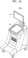
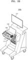
- FIGS. 2A , 2B , and 2C An example of the ultrasound imaging apparatus 100 according to an embodiment is further described in relation to FIGS. 2A , 2B , and 2C .
- FIGS. 2A , 2B , and 2C are each a diagram of an ultrasound imaging apparatus according to an embodiment.
- an ultrasound imaging apparatus may include a main display 121 and a sub-display 122.
- One of the main display 121 and the sub-display 122 may be a touch screen.
- At least one of the main display 121 or the sub-display 122 may display an ultrasonic image or various information processed in the ultrasound imaging apparatus (100a and 100b).
- At least one of the main display 121 or the sub-display 122 may be a touch screen, and may receive from a user data input for controlling the ultrasound imaging apparatus (100a and 100b) by providing a graphical user interface (GUI).
- GUI graphical user interface
- the main display 121 may display an ultrasonic image
- the sub-display 122 may display a control panel for controlling the display of the ultrasonic image in the form of GUI.
- the sub-display 122 may receive data input for controlling the display of the image through the control panel displayed in the form of GUI.
- the ultrasound imaging apparatus (100a and 100b) may control the display of the ultrasonic image on the main display 121 by using the received control data.
- the ultrasound imaging apparatus 100b may further include a control panel 165 in addition to the main display 121 and the sub-display 122.
- the control panel 165 may include a button, a trackball, a jog switch, a knop, etc., and may receive data for controlling the ultrasound imaging apparatus 100b from a user.
- the control panel 165 may include a time gain compensation (TGC) button 171, a freeze button 172, etc.
- the TGC button 171 may be a button for setting a TGC value by a depth of an ultrasonic image.
- the ultrasound imaging apparatus 100b may maintain display of a frame image at that time point.
- the button, trackball, jog switch, knop, etc. included in the control panel 165 may be provided as a GUI on the main display 121 or the sub-display 122.
- an ultrasound imaging apparatus 100c may be implemented as a portable type.
- a portable type ultrasound imaging apparatus 100c may include a smartphone, a laptop computer, a PDA, a tablet PC, etc., which include a probe and an application; however, the disclosure is not limited thereto.
- the ultrasound imaging apparatus 100c may include a probe 20 and a main body 40, and the probe 20 may be connected to a side of the main body 40 in a wired or wireless manner.
- the main body 40 may include a touch screen 145.
- the touch screen 145 may display an ultrasonic image, various information processed in the ultrasound imaging apparatus 100c, a GUI, etc.
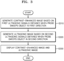
- FIG. 3 is a flowchart illustrating a method of operating an ultrasound imaging apparatus according to an embodiment.
- the ultrasound imaging apparatus 100 may scan an object when the probe 20 sweeps the object.
- the probe 20 may sweep the object in a first direction and a second direction opposite to the first direction.
- the probe 20 may sweep the object in an elevation direction by driving of a motor.
- the probe 20 may scan an object while rotating or moving by a certain distance in a first direction in which the elevation increases and may scan the object while rotating or sweeping by a certain distance in a second direction in which the elevation decreases.
- the disclosure is not limited thereto.
- the probe 20 when the probe 20 is a 2D probe in which a plurality of transducers are arranged in an azimuth direction and an elevation direction, the probe 20 may sweep the object electrically.
- the probe 20 when the probe 20 is a 2D probe, the reciprocation in the first direction and the second direction may be unnecessary, and an object may be scanned when the probe 20 sweeps the object in one direction.
- the ultrasound imaging apparatus 100 may generate a contrast-enhanced image based on first ultrasonic signals obtained when the probe 20 sweeps the object in the first direction (S310).
- the ultrasound imaging apparatus 100 may generate a contrast-enhanced image of the object 10 by irradiating an ultrasonic signal to the object 10 when the probe 20 sweeps the object in the first direction and receiving an echo signal for the irradiated ultrasonic signal.
- the ultrasound imaging apparatus 100 may operate in a contrast-enhanced image mode.
- a contrast-enhanced image may be an image showing various contrast patterns which appear when a microbubble ultrasonography contrast agent injected into the object 10 is spread to blood vessels and organ tissues of the object 10.
- a contrast-enhanced image may be imaged by using the characteristics that echo signals reflected from microbubbles constituting an ultrasound contrast agent are shown as a strong signal compared to normal tissues.
- a transmission and reception method in which normal tissue signals are minimized and contrast-enhanced signals are emphasized in an image may be used to be differentiated from transmission and reception methods of tissue images.
- microbubbles Unlike human tissues, microbubbles have non-linear characteristics resonating at a particular frequency, and when an ultrasonic signal corresponding the resonant frequency, microbubbles may generate a relatively greater echo signal than tissues.
- a signal having a lower voltage than a tissue image transmission signal may be used such that microbubbles are not destroyed in a human body.
- An ultrasound imaging apparatus may obtain a contrast-enhanced image by using a contrast-enhanced image transmission and reception method in the contrast-enhanced image mode.
- the contrast-enhanced transmission and reception method may include pulse inversion (PI), power modulation (PM), power modulated pulse inversion (PMPI), etc.
- the PI may be a transmission and reception method of obtaining a harmonic signal by irradiating two phase-inverted ultrasound transmission signals (waveform having a phase difference of 180°) to an object and summing echo signals reflected from the object.
- echo signal reflected from tissues may cancel each other out, and a harmonic signal may not be generated.
- echo signals reflected from a contrast agent may not cancel each other out, and a harmonic signal (contrast agent harmonic signal) may be generated.
- Such harmonic signal may include excellent resolution characteristics.
- the PM may be a transmission and reception method of irradiating a plurality of ultrasound transmission signals of different amplitudes to an object, scaling echo signals reflected from the object by a transmission amplitude difference, and then obtaining a non-linear fundamental signal through subtraction.
- the ultrasound imaging apparatus 100 may irradiate two consecutive ultrasound transmission signals, one of which has an amplitudes twice the amplitude of the other, to an object, double an echo signal by an ultrasound transmission signal of less amplitude (first ultrasound transmission signal), and carry out subtraction with respect to an ultrasound transmission signal of greater amplitude (second ultrasound transmission signal).
- echo signals reflected from tissues in a particular low-voltage section may cancel each other out.
- a signal component (contrast agent non-linear fundamental signal) may be generated.
- Such non-linear fundamental signal may have excellent medium penetration characteristics.
- the ultrasound imaging apparatus 100 may implement the PM by adjusting the amplitude of the ultrasound transmission signal using a transmission voltage.
- the ultrasound imaging apparatus 100 may implement the PM by controlling an effective transmitting aperture of the probe while maintaining the transmission voltage.
- the ultrasound imaging apparatus 100 may have a halved effective transmitting aperture.
- an error value due to voltage control may be minimized.
- the disclosure is not limited thereto.
- the PMPI may be a method using both of PI and PM, in which ultrasound transmission signals having reversed phases and different amplitudes are irradiated to an object to simultaneously obtain a contrast agent non-linear fundamental signal and a harmonic signal.
- the ultrasound imaging apparatus 100 may obtain a contrast agent non-linear fundamental signal and a harmonic signal simultaneously based on an echo signal obtained by using a plurality of transducers, an echo signal obtained by using even-numbered transducers among the plurality of transducers, and an echo signal obtained by using odd-numbered transducers among the plurality of transducers.
- an ultrasound transmission signal for a plurality of transducers and an ultrasound transmission signal for even/odd-numbered transducers may have a relation of reversed phase.
- the ultrasound imaging apparatus 100 may obtain a contrast-enhanced image by modulating a phase, an amplitude, etc. of an ultrasound transmission signal using the contrast-enhanced image transmission and reception methods described above.
- the contrast-enhanced image transmission and reception methods are not limited thereto.
- the contrast-enhanced mode it may be used a transmission and reception mode devised to emphasize a contrast-enhanced signal and effectively remove a tissue signal by applying an ultrasonic signal corresponding to a resonant frequency of microbubbles of a contrast agent under particular low-voltage conditions that do not destroy the microbubbles of the contrast agent.
- Ultrasonic images obtained in the contrast-enhanced image mode may be referred to as contrast-enhanced images.
- the disclosure is not limited thereto.
- Specific low-voltage conditions used in the contrast-enhanced mode may vary according to a contrast agent.
- the contrast agent may include SonoVue (Bracco SpA, Italy), Sonazoid (GE healthcare, USA), Definity (Lantheus Medical Imaging, USA), Optison (GE Healthcare, USA), etc.
- Specific low-voltage conditions for the above-listed ultrasound contrast agent may include voltage conditions corresponding to a mechanical index of 0.3 or less.
- the disclosure is not limited thereto.
- the ultrasound imaging apparatus 100 may generate an ultrasonic image based on second ultrasonic signals obtained when the probe 20 sweeps the object in the second direction (S320).
- the ultrasound imaging apparatus 100 may generate an ultrasonic image of the object 10 by irradiating an ultrasonic signal to the object 10 when the probe 20 sweeps the object in the second direction and receiving an echo signal for the irradiated ultrasonic signal.
- the ultrasound imaging apparatus 100 may operate in a B mode and obtain a tissue image.
- the ultrasound imaging apparatus 100 may obtain B mode data about an object and generate and display a B mode ultrasonic image (tissue image) based on the B mode data.
- the ultrasound imaging apparatus 100 may extract B mode components from the ultrasonic data and generate a B mode image in which intensity is expressed as luminance based on the extracted B mode components.
- the ultrasound imaging apparatus 100 may generate a Doppler (color Doppler or power Doppler) image, an elastography image, a microvascular image, etc.
- Doppler color Doppler or power Doppler
- the disclosure is not limited thereto.
- the Doppler image may include an image showing the speed or intensity of blood flow in an object.
- the ultrasound imaging apparatus 100 may irradiate a plurality of consecutive ultrasonic signals to an object and obtain signals reflected from moving blood flow. Based on the obtained reflected signals, the ultrasound imaging apparatus 100 may detect a frequency shift value due to the Doppler shift effect and obtain a speed or intensity of blood flow after removing a tissue signal using clutter filtering.
- An elastography image may include an image showing a degree of modification of an object due to an ultrasonic signal irradiated to the object.
- a microvascular image may include an image showing slow micro-blood flows included in an object.
- the ultrasound imaging apparatus 100 may irradiate a plurality of consecutive ultrasonic signals to an object and obtain signals reflected from moving blood flow. Based on the reflected signals, the ultrasound imaging apparatus 100 may identify slow micro-blood flows through singular value decomposition (SVD).
- SSVD singular value decomposition
- the ultrasound imaging apparatus 100 may display the contrast-enhanced image and the ultrasonic image respectively obtained in Operation 310 (S310) and Operation 320 (S320) on a display.
- the ultrasound imaging apparatus 100 may display the contrast-enhanced image and the ultrasonic image on one screen image.
- the ultrasound imaging apparatus 100 may display a 2D, 3D, or 4D contrast-enhanced image of an object in a first area.
- the ultrasound imaging apparatus 100 may display a 2D, 3D, or 4D tissue image (e.g., B mode image) of an object in a second area.
- the ultrasound imaging apparatus 100 may display a 2D, 3D, or 4D Doppler image, elastography image, microvascular image, etc. of an object in the second area. Size or ratio of the first area and the second area may be set or adjusted based on a user input.
- the ultrasound imaging apparatus 100 may provide switching between contrast-enhanced image and the ultrasonic image on the display based on a user input. Alternatively, the ultrasound imaging apparatus 100 may overlay the contrast-enhanced image and the ultrasonic image on the display. However, the disclosure is not limited thereto.
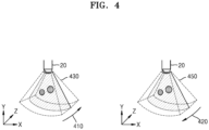
- FIG. 4 is a diagram illustrating a method of obtaining a contrast-enhanced image and an ultrasonic image by an ultrasound imaging apparatus according to an embodiment.
- an object may be scanned when the probe 20 sweeps the object in a first direction 410 and a second direction 420 opposite to the first direction 410. Accordingly, the ultrasound imaging apparatus 100 according to an embodiment may obtain an ultrasound volume data of the object.
- the probe 20 when the probe 20 is a 1D probe in which a plurality of transducers included therein are arranged in an azimuth direction, the probe 20 may sweep the object in an elevation direction by driving of a motor.
- the probe 20 may transmit an ultrasonic signal to an object while rotating or moving in a forward direction in which the elevation increase and in a backward direction in which the elevation decreases and receive an echo signal reflected from the object.
- the ultrasound imaging apparatus 100 may operate in a contrast-enhanced mode.
- the contrast-enhanced mode may use a transmission and reception mode devised to effectively emphasize a contrast-enhanced signal by applying an ultrasonic signal corresponding to a resonant frequency of microbubbles of a contrast agent under particular low-voltage conditions that do not destroy the microbubbles of the contrast agent.
- the ultrasound imaging apparatus 100 may generate a contrast-enhanced image in the contrast-enhanced mode.
- a contrast-enhanced image may be an image generated by using the characteristics that echo signals reflected from microbubbles constituting an ultrasound contrast agent are shown as a strong signal compared to normal tissues.
- the ultrasound imaging apparatus 100 may obtain 2D contrast-enhanced images corresponding to a plurality of cross-sections of an object and generate a 3D contrast-enhanced image 430 (contrast-enhanced volume) based on the 2D contrast-enhanced images.
- the ultrasound imaging apparatus 100 may operate in the B mode.
- the ultrasound imaging apparatus 100 may generate a B mode ultrasonic image (tissue image).
- the ultrasound imaging apparatus 100 may operate in a Doppler mode, a elastography mode, etc.
- the ultrasound imaging apparatus 100 may generate a B mode image (tissue image).
- the ultrasound imaging apparatus 100 may generate a color Doppler image, a power Doppler image, an elastography image, a microvascular image, etc.
- the ultrasound imaging apparatus 100 may adjust a resolution of a 3D tissue image 450 to be different from a resolution of the 3D contrast-enhanced image 430 by generating the 3D contrast-enhanced image 430 or the 3D tissue image 450 according to a sweeping direction.
- the ultrasound imaging apparatus 100 may set the number of 2D tissue images constituting the 3D tissue image 450 to be different from the number of 2D contrast-enhanced images constituting the 3D contrast-enhanced image 430. Moreover, the ultrasound imaging apparatus 100 may set the number of scanlines constituting one 2D tissue image to be different from the number of scanlines constituting one 2D contrast-enhanced image.
- a 4D contrast-enhanced image and a 4D tissue image may be generated.
- the ultrasound imaging apparatus 100 may generate a first 3D contrast-enhanced image, and when the probe 20 rotates or moves in the second direction opposite to the first direction 410, the ultrasound imaging apparatus 100 may generate a first 3D tissue image.
- the ultrasound imaging apparatus 100 may generate a second 3D contrast-enhanced image, and when the probe 20 rotates or moves again in the second direction opposite to the first direction 410, the ultrasound imaging apparatus 100 may generate a second 3D tissue image.
- the ultrasound imaging apparatus 100 may generate a plurality of 3D contrast-enhanced images. Based on the plurality of 3D contrast-enhanced images, the ultrasound imaging apparatus 100 may generate a 4D contrast-enhanced image.
- the ultrasound imaging apparatus 100 may generate a plurality of 3D tissue images. Based on the plurality of 3D tissue images, the ultrasound imaging apparatus 100 may generate a 4D tissue image.
- the ultrasound imaging apparatus 100 may adjust the resolution of the 3D contrast-enhanced image 430 and the resolution of the 3D tissue image 450 to be different from each other and may adjust the volume rate of the 4D contrast-enhanced image and the 4D tissue image.
- the ultrasound imaging apparatus 100 may obtain only a contrast-enhanced image, and when the probe 20 sweeps the object in the second direction (backward direction), the ultrasound imaging apparatus 100 may obtain a tissue image to prevent image shaking.
- FIG. 5 is a diagram illustrating a method of generating a 3D contrast-enhanced image and a 3D tissue image by an ultrasound imaging apparatus according to an embodiment.
- the ultrasound imaging apparatus 100 when the probe 20 sweeps the object in a first direction 510, the ultrasound imaging apparatus 100 may obtain a plurality of 2D contrast-enhanced images corresponding to a plurality of cross-sections 530 of the object 10 based on the obtained first ultrasonic signals.
- FIG. 5 illustrates the object 10 and positions of the plurality of cross-sections 530 corresponding to the plurality of 2D contrast-enhanced image seen from a lens surface of the probe 20.
- the ultrasound imaging apparatus 100 may perform scanning in a third direction 535. As the scanning is performed in the third direction 535 while the probe 20 sweeps the object in the first direction 510, the plurality of cross-sections 530 corresponding to the plurality of 2D contrast-enhanced images may be inclined in a sweeping direction.
- the ultrasound imaging apparatus 100 may obtain a plurality of 2D tissue images corresponding to a plurality of cross-sections 540 of the object 10 based on the obtained second ultrasonic signals.
- FIG. 5 illustrates the object 10 and the plurality of cross-sections 540 corresponding to the plurality of 2D tissue images seen from a lens surface of the probe 20.
- the ultrasound imaging apparatus 100 may perform scanning in a fourth direction 545.
- the plurality of cross-sections 530 corresponding to the plurality of 2D tissue images may be inclined in a sweeping direction (second direction).
- a scanning direction 535 at the time when the probe 20 sweeps the object in the first direction 510 may be opposite to a scanning direction 545 at the time when the probe 20 sweeps the object in the second direction 520.
- the positions of the first cross-sections 530 may be identical to the positions of the second cross-sections 540.
- the ultrasound imaging apparatus 100 may generate a 3D contrast-enhanced image and a 3D tissue image which correspond to the same volume.
- a transmission signal transmitted to an object in the tissue image mode (e.g., B mode) for generating a tissue image may destroy microbubbles of a contrast agent. Accordingly, when the positions of the first cross-sections are identical to the positions of the second cross-sections, microbubbles of the contrast agent at the second cross-sections may be destroyed when 2D tissue images corresponding to the second cross-sections are generated, and after this, the quality of a contrast-enhanced image generated at the first cross-sections having the same positions as the second cross-sections may decrease.
- FIG. 6 is a diagram illustrating a method of generating a 3D contrast-enhanced image and a 3D tissue image by an ultrasound imaging apparatus according to an embodiment.
- the ultrasound imaging apparatus 100 when the probe 20 sweeps the object in a first direction 610, the ultrasound imaging apparatus 100 may obtain a plurality of 2D contrast-enhanced images corresponding to a plurality of cross-sections 630 of the object 10 based on the obtained first ultrasonic signals.
- FIG. 6 illustrates the object 10 and positions of the plurality of cross-sections 630 corresponding to the plurality of 2D contrast-enhanced image seen from a lens surface of the probe 20.
- the ultrasound imaging apparatus 100 may perform scanning in a third direction 635. As the scanning is performed in the third direction 635 while the probe 20 sweeps the object in the first direction 610, the plurality of cross-sections 630 corresponding to the plurality of 2D contrast-enhanced images may be inclined in a sweeping direction.
- the ultrasound imaging apparatus 100 may obtain a plurality of 2D tissue images corresponding to a plurality of cross-sections 640 of the object 10 based on the obtained second ultrasonic signals.
- FIG. 6 illustrates the object 10 and the plurality of cross-sections 640 corresponding to the plurality of 2D tissue images seen from a lens surface of the probe 20.
- the ultrasound imaging apparatus 100 may perform scanning in a fourth direction 645.
- the plurality of cross-sections 640 corresponding to the plurality of 2D tissue images may be inclined in a sweeping direction (second direction).
- a scanning direction 635 at the time when the probe 20 sweeps the object in the first direction 610 may be identical to a scanning direction 645 at the time when the probe 20 sweeps the object in the second direction 620. Accordingly, the positions of the first cross-sections 630 may be different from the positions of the second cross-sections 640.
- Microbubbles of a contrast agent may be destroyed by an ultrasound transmission signals, and more specifically, the microbubbles may be destroyed more significantly by an ultrasound transmission signal transmitted in the tissue image mode than the contrast-enhanced image mode.
- a contrast-enhanced image may be an image generated based on an echo signal reflected from the microbubbles, and the quality of the contrast-enhanced image may deteriorate when the amplitude of the echo signal reflected from the microbubbles decreases due to destruction of the microbubbles.
- the ultrasound imaging apparatus 100 may increase duration of microbubbles of a contrast agent by avoiding transmission of a transmission signal for generating a contrast-enhanced image and a transmission signal for generating a tissue image to the same point.
- FIG. 7 is a diagram illustrating a method of generating a 3D contrast-enhanced image and a 3D tissue image by an ultrasound imaging apparatus according to an embodiment.
- the ultrasound imaging apparatus 100 when the probe 20 sweeps the object in a first direction 710, the ultrasound imaging apparatus 100 may obtain a plurality of 2D contrast-enhanced images corresponding to a plurality of cross-sections 730 of the object 10 based on the obtained first ultrasonic signals.
- FIG. 7 illustrates the object 10 and positions of the plurality of cross-sections 730 corresponding to the plurality of 2D contrast-enhanced image seen from a lens surface of the probe 20.
- the ultrasound imaging apparatus 100 may perform scanning in a third direction 735. As the scanning is performed in the third direction 735 while the probe 20 sweeps the object in the first direction 710, the plurality of cross-sections 730 corresponding to the plurality of 2D contrast-enhanced images may be inclined in a sweeping direction.
- the ultrasound imaging apparatus 100 may obtain a plurality of 2D tissue images corresponding to a plurality of cross-sections 740 of the object 10 based on the obtained second ultrasonic signals.
- FIG. 7 illustrates the object 10 and the plurality of cross-sections 740 corresponding to the plurality of 2D tissue images seen from a lens surface of the probe 20.
- the ultrasound imaging apparatus 100 may perform scanning in a fourth direction 745.
- the plurality of cross-sections 740 corresponding to the plurality of 2D tissue images may be inclined in a sweeping direction (second direction).
- a scanning direction 735 at the time when the probe 20 sweeps the object in the first direction 710 may be different from a scanning direction 745 at the time when the probe 20 sweeps the object in the second direction 720.
- the ultrasound imaging apparatus 100 may control rotation or movement of the probe 20 such that the first cross-sections 730 and the second cross-sections 740 may not overlap and intersect each other.
- the ultrasound imaging apparatus 100 may transmit an ultrasonic signal at an even-numbered angle such as 0°, 2°, 4°, etc. in the first direction 710 when the probe 20 sweeps the object in the first direction 710 and transmit an ultrasonic signal at an odd-numbered angle such as 1°, 3°, 5°, etc. when the probe 20 sweeps the object in the second direction 720.
- the ultrasound imaging apparatus 100 may avoid transmission of a transmission signal for a contrast-enhanced image and a transmission signal for a tissue image to the same position.
- the disclosure is not limited thereto.
- the ultrasound imaging apparatus 100 may increase duration of microbubbles of a contrast agent and prevent deterioration of quality of contrast-enhanced images by avoiding transmission of a transmission signal for generating a contrast-enhanced image and a transmission signal for generating a tissue image to the same point.
- FIGS. 5 to 7 illustrate that the ultrasound imaging apparatus 100 obtains a plurality of 2D contrast-enhanced images during the sweeping in the first direction and obtains a plurality of 2D tissue images during the sweeping in the second direction; however, the disclosure is not limited thereto.
- the ultrasound imaging apparatus 100 may obtain during the sweeping in the first direction a plurality of 2D contrast-enhanced images corresponding to a plurality of cross-sections of the object 10 based on the obtained first ultrasonic signals and obtain during the re-sweeping in the first direction a plurality of 2D tissue images corresponding to cross-sections of the object 10 based on the obtained second ultrasonic signals.
- the ultrasound imaging apparatus 100 may obtain during the sweeping in the second direction a plurality of 2D contrast-enhanced images corresponding to a plurality of cross-sections of the object 10 based on the obtained first ultrasonic signals and obtain during the re-sweeping in the second direction a plurality of 2D tissue images corresponding to cross-sections of the object 10 based on the obtained second ultrasonic signals.
- the ultrasound imaging apparatus 100 may obtain a 3D contrast-enhanced image or a 3D tissue image through the sweeping in the first direction or in the second direction.
- the ultrasound imaging apparatus 100 may obtain a 4D contrast-enhanced image or a 4D tissue image by repeating the sweeping in the first direction or in the second direction and obtaining ultrasonic signals.
- FIG. 8 is a diagram illustrating a method of generating a 3D contrast-enhanced image and a 3D tissue image by an ultrasound imaging apparatus according to an embodiment.
- the ultrasound imaging apparatus 100 when the probe 20 sweeps the object in a first direction 810, the ultrasound imaging apparatus 100 may obtain a plurality of 2D contrast-enhanced images corresponding to a plurality of cross-sections 840 of the object 10 based on the obtained first ultrasonic signals.
- FIG. 8 illustrates the object 10 and positions of the plurality of cross-sections 840 corresponding to the plurality of 2D contrast-enhanced image seen from a lens surface of the probe 20.
- the ultrasound imaging apparatus 100 may perform scanning in a third direction 830.
- the probe 20 may be a 2D probe in which a plurality of transducers are arranged in a 2D array.
- a 2D probe may scan an object by electrical sweeping instead of motor-driven sweeping.
- the reciprocating motion between the first direction and the second direction may become unnecessary.
- the cross-sections 840 may not be inclined in a sweeping direction.
- the ultrasound imaging apparatus 100 may obtain second ultrasonic signals during a second sweeping of the probe 20 in the first direction 810 or in the second direction 820.
- the second sweeping may be performed in any direction; however, given the refusion time of microbubbles of contrast agent destroyed during the first sweeping, it may be effective to sweep the probe 20 in the first direction 810.
- the ultrasound imaging apparatus 100 may perform scanning in the third direction 830 during the second sweeping of the probe 20 in the first direction 810 or in the second direction 820.
- the ultrasound imaging apparatus 100 may obtain a plurality of 2D tissue images corresponding to a plurality of cross-sections 850 of the object 10 based on the second ultrasonic signals.
- FIG. 8 illustrates the object 10 and the plurality of cross-sections 850 corresponding to the plurality of 2D tissue images seen from a lens surface of the probe 20.
- the ultrasound imaging apparatus 100 may control an ultrasonic signal transmission angle of the probe 20 such that the first cross-sections 840 and the second cross-sections 850 may be parallel with each other and intersect each other without overlapping.
- the ultrasound imaging apparatus 100 may transmit an ultrasonic signal at an even-numbered angle such as 0°, 2°, 4°, etc. in the first direction 810 during the first sweeping of the probe 20 in the first direction 810 and transmit an ultrasonic signal at an odd-numbered angle such as 1°, 3°, 5°, etc. during the second sweeping of the probe 20 in the first direction 810 or in the second direction 820.
- the ultrasound imaging apparatus 100 may avoid transmission of a transmission signal for a contrast-enhanced image and a transmission signal for a tissue image to the same position.
- the disclosure is not limited thereto.
- the ultrasound imaging apparatus 100 may increase duration of microbubbles of a contrast agent and prevent deterioration of quality of contrast-enhanced images by avoiding transmission of a transmission signal for generating a contrast-enhanced image and a transmission signal for generating a tissue image to the same point.
- FIG. 9 is a diagram illustrating a method of generating a contrast-enhanced image by an ultrasound imaging apparatus according to an embodiment.
- the ultrasound imaging apparatus 100 may generate a plurality of 2D contrast-enhanced images corresponding to a plurality of first cross-sections 930 based on the obtained ultrasonic signals (contrast-enhanced signals).
- the ultrasound imaging apparatus 100 may generate a plurality of 2D tissue images corresponding to second cross-sections 940 based on the obtained ultrasonic signals (tissue signals).
- a transmission signal for generating a contrast-enhanced image and a transmission signal for generating a tissue image are transmitted to an overlapping area 950 of the first cross-sections 930 and the second cross-sections 940, more microbubbles of a contrast agent may be destroyed, compared to other areas. Accordingly, an amplitude of an echo signal reflected from the overlapping area 950 of the first cross-sections 930 and the second cross-sections 940 may be less than that of echo signals reflected from other areas.
- the ultrasound imaging apparatus 100 may apply a weighted value 960 to a gain set for the overlapping area 950 to compensate for the echo signal of the overlapping area 950.
- a TGC value set for the overlapping area 950 may be adjusted by applying the weighted value 960 to the TGC value.
- the ultrasound imaging apparatus 100 may apply a gain to which the weighted value 960 is applied to a scanline signal of the overlapping area 950.
- the ultrasound imaging apparatus 100 may apply a weighted value to scanline gain compensation (SGC) set for the overlapping area 950 to adjust an SGC value.
- SGC scanline gain compensation
- Gains may be set by scanline for SGC.
- Gain values may be applied in an analog or digital method.
- the ultrasound imaging apparatus 100 may apply a first gain value to the overlapping area 950 and apply a second gain value less than the first value to other areas.
- the ultrasound imaging apparatus 100 may apply a gain to which a weighted value is applied to the overlapping area 950 when generating a 2D contrast-enhanced image based on an echo signal received from an object.
- the disclosure is not limited thereto.
- FIG. 10 is a diagram illustrating a method of generating a 3D contrast-enhanced image and a 3D tissue image by an ultrasound imaging apparatus according to an embodiment.
- the ultrasound imaging apparatus 100 may adjust a resolution of a 3D contrast-enhanced image and a resolution of a tissue image to adjust a volume rate of a 4D contrast-enhanced image and a 4D tissue image.
- a volume rate may represent a rate of displaying volume data and may show the number of volume images (3D contrast-enhanced image or 3D tissue image) displayed per second.
- the disclosure is not limited thereto.
- the ultrasound imaging apparatus 100 may adjust each of a resolution of a 3D contrast-enhanced image and a resolution of a 3D tissue image.
- the ultrasound imaging apparatus 100 may adjust a resolution of a 3D contrast-enhanced image by adjusting quality of a transmission signal for generating a 3D contrast-enhanced image.
- the ultrasound imaging apparatus 100 may adjust the number of 2D contrast-enhanced images (frames) constituting a 3D contrast-enhanced image and the number of scanlines constituting a 2D contrast-enhanced image.
- the ultrasound imaging apparatus 100 may adjust a resolution of a 3D tissue image by adjusting quality of a transmission signal for generating a 3D tissue image.
- the ultrasound imaging apparatus 100 may adjust the number of 2D tissue images (frames) constituting a 3D tissue image and the number of scanlines constituting a 2D tissue image.
- the ultrasound imaging apparatus 100 may set the number of 2D contrast-enhanced images constituting a 3D contrast-enhanced image to be 6 and the number of 2D tissue images constituting a 3D tissue image to be 6. Moreover, first cross-sections 1010 showing 2D contrast-enhanced images and second cross-sections 1020 showing 2D tissue images may be different from each other and may intersect each other.
- the ultrasound imaging apparatus 100 may set the number of 2D contrast-enhanced images constituting a 3D contrast-enhanced image to be 6 and the number of 2D tissue images constituting a 3D tissue image to be 3. Moreover, third cross-sections 1030 showing 2D contrast-enhanced images and fourth cross-sections 1040 showing 2D tissue images may be different from each other and may intersect each other.
- the ultrasound imaging apparatus 100 may set the number of 2D contrast-enhanced images constituting a 3D contrast-enhanced image to be 6 and the number of 2D tissue images constituting a 3D tissue image to be 3. Moreover, fifth cross-sections 1050 showing 2D contrast-enhanced images and sixth cross-sections 1050 showing 2D tissue images may be different from each other and may not intersect each other.
- the ultrasound imaging apparatus 100 may adjust the volume rate by adjusting the number of 2D contrast-enhanced images constituting a 3D contrast-enhanced image and the number of 2D tissue images constituting a 3D tissue image.
- the volume rate may increase more when the number of 2D contrast-enhanced images constituting a 3D contrast-enhanced image is set to 6, and the number of 2D tissue images constituting a 3D tissue image is set to 3 than when the number of 2D contrast-enhanced images constituting a 3D contrast-enhanced image is set to 6, and the number of 2D tissue images constituting a 3D tissue image is set to 6.
- the volume rate increases, changes in contrast agent flow may be shown more clearly in a contrast-enhanced image.
- FIG. 10 illustrates that the number of scanlines constituting a 2D contrast-enhanced image is the same as that of scanlines constituting a 2D tissue image, when the number of scan lines constituting a 2D tissue image decreases, the volume rate may increase.
- the ultrasound imaging apparatus 100 may increase a volume rate of a contrast-enhanced image while decreasing a resolution of a tissue image.
- FIG. 11 is a diagram illustrating an example of a screen image showing a contrast-enhanced image and a tissue image displayed on a display by an ultrasound imaging apparatus.
- the ultrasound imaging apparatus 100 may display a contrast-enhanced image and a tissue image on one screen image.
- the screen image may include a plurality of areas.
- the ultrasound imaging apparatus 100 may display in each of the plurality of areas at least one of a 2D contrast-enhanced image, a 2D tissue image, a 3D contrast-enhanced image, a 3D tissue image, a 4D contrast-enhanced image, or a 4D tissue image.
- the screen image may be divided into four areas (1110, 1120, 11130, and 1140), and the ultrasound imaging apparatus 100 may display in the first area 1110 a 2D contrast-enhanced image showing a first cross-section of an object among a plurality of 2D contrast-enhanced images and display in the second area 1120 a 2D contrast-enhanced image showing a second cross-section of the object among a plurality of 2D contrast-enhanced images.
- the ultrasound imaging apparatus 100 may display in the third area 1130 a 2D tissue image showing a third cross-section of the object among a plurality of 2D tissue images.
- the ultrasound imaging apparatus 100 may display a 3D contrast-enhanced image or a 4D contrast-enhanced image in the fourth area 1140.
- the disclosure is not limited thereto, and the ultrasound imaging apparatus 100 may display various combinations of contrast-enhanced images and tissue images.
- the ultrasound imaging apparatus 100 may display, in addition to a tissue image, a Doppler image (color Doppler image or a power Doppler image), an elastography image, a microvascular image, etc. together with a contrast-enhanced image.
- the ultrasound imaging apparatus 100 may set a type of image to be displayed in each of the plurality of areas based on a user input. For example, the ultrasound imaging apparatus 100 may determine which image between a contrast-enhanced image and a tissue image is to be displayed and which image among a 2D image, a 3D image, and a 4D image is to be displayed, based on a user input.
- the ultrasound imaging apparatus 100 may adjust a size or a ratio of each of the plurality of areas based on a user input.
- FIG. 12 is a diagram illustrating an example of a screen image showing a contrast-enhanced image and a tissue image displayed on a display by an ultrasound imaging apparatus.
- the ultrasound imaging apparatus 100 may divide the display screen into eight areas and display contrast-enhanced images in four areas (1210, 1220, 1230, and 1240) and non-contrast-enhanced images in the other four areas (1250, 1260, 1270, and 1280).
- the non-contrast-enhanced images may include a tissue image, a Doppler image, an elastography image, a microvascular image, etc.
- the ultrasound imaging apparatus 100 may display 2D contrast-enhanced images showing different cross-sections of an object in the first to third areas 1210, 1220, and 1230.
- the different cross-sections of an object may be a sagittal plane, a transverse plane, and a coronal plane; however, the disclosure is not limited thereto.
- the ultrasound imaging apparatus 100 may display a 4D non-contrast-enhanced image in the eighth area 1280.
- the ultrasound imaging apparatus 100 may display non-contrast-enhanced images of different types in the fifth to eighth areas 1250, 1260, 1270, and 1280.
- the ultrasound imaging apparatus 100 may display a 2D tissue image in the fifth and sixth areas 1250 and 1260, a 2D elastography image in the seventh area 1270, and a 4D color Doppler image in the eighth area 1280.
- a 3D contrast-enhanced image is generated based on an ultrasonic signal obtained when the probe 20 sweeps the object in the first direction
- a 3D non-contrast-enhanced image is generated based on an ultrasonic signal obtained when the probe 20 sweeps the object in the second direction
- a 3D contrast-enhanced image and a 3D non-contrast-enhanced image may be generated sequentially and repeatedly.
- the ultrasound imaging apparatus 100 may display a 3D contrast-enhanced image generated first (first 3D contrast-enhanced image) and a 3D non-contrast-enhanced image generated first (first 3D non-contrast-enhanced image) together at a first time point. After the first time point, when a 3D contrast-enhanced image (second 3D contrast-enhanced image) is generated, the ultrasound imaging apparatus 100 may display the second 3D contrast-enhanced image and the first 3D non-contrast-enhanced image at a second time point.
- the ultrasound imaging apparatus 100 may display the second 3D contrast-enhanced image and the second 3D non-contrast-enhanced image at a third time point.
- the disclosure is not limited thereto.
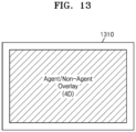
- FIG. 13 is a diagram illustrating an example of a screen image showing a contrast-enhanced image and a tissue image displayed on a display by an ultrasound imaging apparatus.
- the ultrasound imaging apparatus 100 may display an overlay image of a contrast-enhanced image and a non-contrast-enhanced image on a display screen 1310.
- the ultrasound imaging apparatus 100 may display an overlay image of a 3D contrast-enhanced image and a 3D non-contrast-enhanced image or display an overlay image of a 4D contrast-enhanced image and a 4D non-contrast-enhanced image.
- an overlay image of a 4D contrast-enhanced image and a 4D non-contrast-enhanced image is displayed, as described in relation to FIG. 12 , an overlay image of a 3D contrast-enhanced image generated first (first 3D contrast-enhanced image) and a 3D non-contrast-enhanced image generated first (first 3D non-contrast-enhanced image) at a first time point may be displayed.
- the ultrasound imaging apparatus 100 may display an overlay image of the second 3D contrast-enhanced image and the first 3D non-contrast-enhanced image at a second time point.
- the ultrasound imaging apparatus 100 may display an overlay image of the second 3D contrast-enhanced image and the second 3D non-contrast-enhanced image at a third time point.
- the disclosure is not limited thereto.
- the ultrasound imaging apparatus 100 may facilitate identification of specific location of tissues in a contrast-enhanced image by displaying an overlay image of a contrast-enhanced image and a tissue image.
- FIG. 14 is a block diagram illustrating components of an ultrasound diagnostic apparatus according to an embodiment.
- an ultrasound imaging apparatus 1400 may include a processor 1410, a memory 1420, and a display 1430.
- the processor 1410 of FIG. 14 may correspond to at least one of the ultrasound transmission and reception module 110, the processor 120, or the image processor 130 or a combination thereof, and the display 1430 may correspond to the display 140 of FIG. 1 .
- some of the components of the ultrasound imaging apparatus 100 illustrated in FIG. 1 according to an embodiment may be included in the ultrasound imaging apparatus 1400 illustrated in FIG. 14 .
- the processor 1410 may control overall operations of the ultrasound imaging apparatus 1400.
- the processor 1410 may execute one or more programs stored in the memory 1420.
- the memory 1420 may store data, programs, and applications for driving and controlling the ultrasound imaging apparatus 1400.
- the programs stored in the memory 1420 may include one or more instructions.
- the programs (one or more instructions) or applications stored in the memory 1420 may be executed by the processor 1410.
- the processor 1410 may generate a contrast-enhanced image based on first ultrasonic signals obtained when the probe sweeps the object in the first direction.
- the processor 1410 may generate a contrast-enhanced image of the object by irradiating an ultrasonic signal to the object when the probe sweeps the object in the first direction and receiving an echo signal for the irradiated ultrasonic signal. For example, when the probe sweeps the object in the first direction, the processor 1410 may operate in a contrast-enhanced image mode. When operating in the contrast-enhanced mode, the processor 1410 may use a transmission and reception mode devised to emphasize a contrast-enhanced signal and effectively remove a tissue signal by applying an ultrasonic signal corresponding to a resonant frequency of microbubbles of a contrast agent under particular low-voltage conditions that do not destroy the microbubbles of the contrast agent. The processor 1410 may obtain a contrast-enhanced image in the contrast-enhanced mode.
- the processor 1410 may generate an ultrasonic image based on second ultrasonic signals obtained when the probe sweeps the object in the second direction.
- the processor 1410 may generate an ultrasonic image of the object by irradiating an ultrasonic signal to the object when the probe sweeps the object in the second direction and receiving an echo signal for the irradiated ultrasonic signal.
- the processor 1410 may operate in the B mode and obtain a tissue image.
- the processor 1410 may obtain B mode data regarding the object, generate a B mode ultrasonic image (tissue image) based on the B mode data, and control the display 1430 to display thereon the generated image.
- the processor 1410 may extract B mode components from the ultrasonic data and generate a B mode image in which intensity is expressed as luminance based on the extracted B mode components. Or, the processor 1410 may generate a Doppler (color Doppler or power Doppler) image, an elastography image, a microvascular image, etc. However, the disclosure is not limited thereto.
- Doppler color Doppler or power Doppler
- the processor 1410 may display a contrast-enhanced image and an ultrasonic image (non-contrast-enhanced image) on the display 1430.
- the processor 1410 may control the display 1430 to display the contrast-enhanced image and the ultrasonic image on one screen image.
- the display 1430 may display an operational status of the ultrasound imaging apparatus 1400, an ultrasonic image, a user interface, etc.
- the display 1430 may include one or more display panels according to an embodiment, and the display 1430 may be implemented in the form of a touch screen.
- the processor 1410 may control the display 1430 to display a 2D, 3D, or 4D contrast-enhanced image of an object in a first area.
- the processor 1410 may control the display 1430 to display a 2D, 3D, or 4D tissue image (e.g., B mode image) of an object in a second area.
- the processor 1410 may control the display 1430 to display a 2D, 3D, or 4D Doppler image, elastography image, microvascular image, etc. of an object in the second area. Size or ratio of the first area and the second area may be set or adjusted based on a user input.
- the processor 1410 may control the display 1430 to provide switching between a contrast-enhanced image and an ultrasonic image on a display based on a user input.
- the processor 1410 may control the display 1430 to display an overlay image of a contrast-enhanced image and an ultrasonic image.
- the disclosure is not limited thereto.
- the block diagram of the ultrasound diagnostic apparatus (100 and 1400) is for illustrating an embodiment. Components shown in the block diagram may be integrated, added, or omitted according to specifications of actually implemented ultrasound imaging apparatus (100 and 1400). That is, two or more components may be combined into a single component or a single component may be divided into two or more components, when necessary. Moreover, functions performed by each block are for illustrating embodiments, and specific operations and devices are not intended to limit the scope of rights of the disclosure.
- a method of operating an ultrasound imaging apparatus may be implemented in the form of a program command executable by various computer devices and recorded in a computer-readable medium.
- the computer-readable medium may include a program command, a data file, a data structure, etc. separately or combinedly.
- the program command recorded in the medium may be specifically designed and configured for the disclosure or may be made public and usable to a person skilled in the field of computer software.
- the computer-readable recording medium may include a hardware device specifically configured to store and execute program commands, such as magnetic media including a hard disk, a floppy disk, and a magnetic tape, optical media such as a CD-ROM and a DVD, magneto-optical media such as a floptical disk, ROM, RAM, flash memory, etc.
- the program commands may include not only machine language code, which is made by a compiler, but high level language code executable by a computer by using an interpreter, etc.
- An ultrasound diagnostic apparatus and a method of operating an ultrasound diagnostic apparatus may be included and provided in a computer program product.
- a computer program product may be traded between a seller and a buyer.
- a computer program product may include a S/W program and a computer-readable record medium in which the S/W program is stored.
- a computer program product may include a product in the form of a S/W program electronically distributed by a manufacturer of electronic devices or an electronic market (e.g., Google Play Store, App Store, etc.) At least a part of the S/W program may be stored in a storage medium or temporarily generated for electronic distribution.
- a storage medium may be a storage medium of a manufacturer server, an electronic market server, or a relay server temporarily storing the S/W program.
- the computer program product may include a storage medium of a server or a storage medium of a client device in a system consisting of a server and a client device.
- a third device e.g., smartphone
- the computer program product may include a storage medium of the third device.
- the computer program product may include a S/W program itself which is transmitted from a server to a client device or a third device or transmitted from a third device to a client device.
- one of the server, client device, and third device may execute the computer program product and perform the method according to the embodiments.
- two or more of the server, client device, and third device may execute the computer program product and perform the method according to the embodiments in a distributed manner.
- a server may control a client device connected to the server to perform the method according to the embodiments by executing the computer program product stored in the server (e.g., a cloud server or an artificial intelligence server).
- the server e.g., a cloud server or an artificial intelligence server.
- An ultrasound imaging apparatus may facilitate identification of specific location of tissues in a contrast-enhanced image by displaying a contrast-enhanced image and an ultrasonic image on one screen image.
- An ultrasound imaging apparatus may prevent image shaking due to the backlash phenomenon which may occur during a direction change of a motor which drives the probe for sweeping.
- An ultrasound imaging apparatus may minimize destruction of contrast agent by differentiating cross-sections of an object which correspond to contrast-enhanced images from cross-sections of the object which correspond to a tissue image.
- An ultrasound imaging apparatus may adjust a resolution of each of a contrast-enhanced image and a tissue image and may increase a volume rate.
Landscapes
- Health & Medical Sciences (AREA)
- Life Sciences & Earth Sciences (AREA)
- Engineering & Computer Science (AREA)
- Medical Informatics (AREA)
- Public Health (AREA)
- Physics & Mathematics (AREA)
- General Health & Medical Sciences (AREA)
- Nuclear Medicine, Radiotherapy & Molecular Imaging (AREA)
- Radiology & Medical Imaging (AREA)
- Molecular Biology (AREA)
- Heart & Thoracic Surgery (AREA)
- Biomedical Technology (AREA)
- Pathology (AREA)
- Surgery (AREA)
- Animal Behavior & Ethology (AREA)
- Biophysics (AREA)
- Veterinary Medicine (AREA)
- Computer Vision & Pattern Recognition (AREA)
- Hematology (AREA)
- Computer Graphics (AREA)
- General Engineering & Computer Science (AREA)
- General Physics & Mathematics (AREA)
- Theoretical Computer Science (AREA)
- Epidemiology (AREA)
- Primary Health Care (AREA)
- Ultra Sonic Daignosis Equipment (AREA)
Abstract
Description
- This application is based on and claims priority under 35 U.S.C. §119 to
Korean Patent Application No. 10-2023-0117630, filed on September 5, 2023 - One or more embodiments of the disclosure relate to an ultrasound imaging apparatus, and more particularly, to an ultrasound imaging apparatus capable of obtaining a contrast-enhanced image and a tissue image of an object and an operating method thereof.
- Recently, various medical imaging apparatuses for imaging and obtaining information about tissues and organs of the human body have been widely used for the purposes of early diagnosis and treatment of diseases. Such medical imaging apparatuses may include an ultrasound diagnostic apparatus, a computed tomography (CT) apparatus, and a magnetic resonance imaging (MRI) apparatus.
- Ultrasound diagnostic apparatuses obtain an image of a part inside an object by irradiating an ultrasonic signal generated from a transducer of a probe to the object and receiving information about an echo signal reflected from the object. In particular, ultrasound diagnostic apparatuses are used for medical purposes, such as observation of an inside part of an object, detection of foreign matters, measurement of injury, etc. As ultrasound diagnostic apparatuses have higher stability than other diagnostic apparatuses using X-ray, are capable of displaying an image in real time, and are free from radiation exposure, ultrasound diagnostic apparatuses are widely used along with other image diagnostic apparatuses.
- Lately, contrast-enhanced images obtained by using an ultrasound contrast agent have been widely used for diagnosis of various lesions. Ultrasound contrast agents may be injected into the human body, and the injected ultrasound contrast agent may circulate inside the human body. Microbubbles of the contrast agent may function as a strong reflector for ultrasonic signals. Accordingly, ultrasonic signals reflected from microbubbles are shown as a strong signal in an ultrasonic image, compared to normal tissues.
- Provided are an ultrasound imaging apparatus capable of providing a contrast-enhanced image and a tissue image of an object and an operating method thereof.
- Additional aspects will be set forth in part in the description which follows and, in part, will be apparent from the description, or may be learned by practice of the presented embodiments of the disclosure.
- In accordance with an aspect of the disclosure, an ultrasound imaging apparatus includes a display, a memory storing one or more instructions, and a processor configured to execute the one or more instructions stored in the memory, wherein, by executing the one or more instructions, the processor is further configured to generate at least one contrast-enhanced image of an object based on first ultrasonic signals obtained when a probe sweeps the object in a first direction, generate at least one ultrasonic image of the object based on second ultrasonic signals obtained when the probe sweeps the object in a second direction different from the first direction, and control the display to display the at least one contrast-enhanced image and the at least one ultrasonic image.
- The first ultrasonic signals may include contrast-enhanced signals reflected from a contrast agent, and the second ultrasonic signals may include tissue signals reflected from tissues of the object.
- The processor may be further configured to execute the one or more instructions to generate, based on the first ultrasonic signals, contrast-enhanced images corresponding to first cross-sections of the object which do not intersect each other and generate, based on the second ultrasonic signals, ultrasonic images corresponding to second cross-sections of the object which do not intersect each other, wherein the first cross-sections are different from the second cross-sections.
- The first cross-sections and the second cross-sections may not intersect each other.
- The processor may be further configured to execute the one or more instructions to perform compensation for the first ultrasonic signals by applying a first gain value to the first ultrasonic signals obtained from a first area in which the first cross-sections and the second cross-sections intersect each other and applying a second gain value to the first ultrasonic signals obtained from areas other than the first area, wherein the first gain value is set to be greater than the second gain value.
- The processor may be further configured to execute the one or more instructions to generate a three-dimensional (3D) contrast-enhanced image based on the contrast-enhanced images corresponding to the first cross-sections and generate a 3D ultrasonic image based on the ultrasonic images corresponding to the second cross-sections.
- The 3D contrast-enhanced image may have a first resolution, and the 3D ultrasonic image may have a second resolution different from the first resolution.
- The processor may be further configured to execute the one or more instructions to set the number of the contrast-enhanced images constituting the 3D contrast-enhanced image to be different from the number of the ultrasonic images constituting the 3D ultrasonic image.
- The first resolution may be determined based on at least one of the number of the contrast-enhanced images constituting the 3D contrast-enhanced image or the number of scanlines constituting one contrast-enhanced image, and the second resolution may be determined based on at least one of the number of the ultrasonic images constituting the 3D ultrasonic image or the number of scanlines constituting one ultrasonic image.
- A volume rate of the 3D contrast-enhanced image and the 3D ultrasonic image may be determined based on the number of the contrast-enhanced images constituting the 3D contrast-enhanced image, the number of scanlines constituting one contrast-enhanced image, the number of the ultrasonic images constituting the 3D ultrasonic image, and the number of scanlines constituting one ultrasonic image.
- The at least one ultrasonic image may include at least one of a tissue image, a Doppler image, an elastography image, or a microvascular image.
- The processor may be further configured to execute the one or more instructions to generate at least one second ultrasonic image of the object based on third ultrasonic signals obtained when the probe sweeps the object in a third direction different from the first direction and the second direction and control the display to display the at least one second ultrasonic image.
- In accordance with another aspect of the disclosure, a method of operating an ultrasound imaging apparatus includes generating at least one contrast-enhanced image of an object based on first ultrasonic signals obtained when a probe sweeps the object in a first direction, generating at least one ultrasonic image of the object based on second ultrasonic signals obtained when the probe sweeps the object in a second direction different from the first direction, and displaying the at least one contrast-enhanced image and the at least one ultrasonic image.
- The present disclosure will become apparent and more readily appreciated from the following description, taken in conjunction with the accompanying drawings wherein like reference numerals denote like structural elements.
- The above and other aspects, features, and advantages of certain embodiments of the disclosure will be more apparent from the following description taken in conjunction with the accompanying drawings, in which:
-
FIG. 1 is a block diagram illustrating components of an ultrasound imaging apparatus according to an embodiment; -
FIGS. 2A ,2B , and2C are each a diagram of an ultrasound imaging apparatus according to an embodiment; -
FIG. 3 is a flowchart illustrating a method of operating an ultrasound imaging apparatus according to an embodiment; -
FIG. 4 is a diagram illustrating a method of obtaining a contrast-enhanced image and an ultrasonic image by an ultrasound imaging apparatus according to an embodiment; -
FIG. 5 is a diagram illustrating a method of generating a three-dimensional (3D) contrast-enhanced image and a 3D tissue image by an ultrasound imaging apparatus according to an embodiment; -
FIG. 6 is a diagram illustrating a method of generating a 3D contrast-enhanced image and a 3D tissue image by an ultrasound imaging apparatus according to an embodiment; -
FIG. 7 is a diagram illustrating a method of generating a 3D contrast-enhanced image and a 3D tissue image by an ultrasound imaging apparatus according to an embodiment; -
FIG. 8 is a diagram illustrating a method of generating a 3D contrast-enhanced image and a 3D tissue image by an ultrasound imaging apparatus according to an embodiment; -
FIG. 9 is a diagram illustrating a method of generating a contrast-enhanced image by an ultrasound imaging apparatus according to an embodiment; -
FIG. 10 is a diagram illustrating a method of generating a 3D contrast-enhanced image and a 3D tissue image by an ultrasound imaging apparatus according to an embodiment; -
FIG. 11 is a diagram illustrating an example of a screen image showing a contrast-enhanced image and a tissue image displayed on a display by an ultrasound imaging apparatus; -
FIG. 12 is a diagram illustrating an example of a screen image showing a contrast-enhanced image and a tissue image displayed on a display by an ultrasound imaging apparatus; -
FIG. 13 is a diagram illustrating an example of a screen image showing a contrast-enhanced image and a tissue image displayed on a display by an ultrasound imaging apparatus; and -
FIG. 14 is a block diagram illustrating components of an ultrasound diagnostic apparatus according to an embodiment. - Reference will now be made in detail to embodiments, examples of which are illustrated in the accompanying drawings, wherein like reference numerals refer to like elements throughout. In this regard, the present embodiments may have different forms and should not be construed as being limited to the descriptions set forth herein. Accordingly, the embodiments are merely described below, by referring to the figures, to explain aspects of the present description. As used herein, the term "and/or" includes any and all combinations of one or more of the associated listed items. Expressions such as "at least one of," when preceding a list of elements, modify the entire list of elements and do not modify the individual elements of the list.
- The specification is intended to describe the principle and embodiments of the disclosure such that the scope of rights of the disclosure is clarified, and the disclosure may be carried out by a person skilled in the art. The embodiments of the disclosure may be embodied in many different forms.
- Throughout the specification, like reference numerals denote like components. The specification does not necessarily describe all elements of the embodiments, and general features of the field to which the disclosure pertains and redundant description in the embodiments may be omitted. Such terms as "module" or "unit" used throughout the specification may be implemented by a software, a hardware, or a combination thereof, and in some embodiments, a plurality of "modules" or "units" may be implemented by one element or a "module" or "unit" may include a plurality of elements.
- Hereinafter, the operational principle and embodiments of the disclosure are described by referring to the attached drawings.
- Throughout the specification, the term "image" may include a medical image obtained by a medical imaging apparatus, such as a magnetic resonance imaging (MRI) apparatus, a computed tomography (CT) apparatus, an ultrasound imaging apparatus, an X-ray apparatus, etc.
- The term "object" used herein refers to a target of imaging and may include a person, an animal, or parts thereof. For example, an object may include a body part (organ) or phantom.
- Throughout the specification, the term "ultrasonic image" refers to an image of an object, which has been processed based on ultrasonic signals transmitted to and then reflected from the object.
- Hereinafter, embodiments of the disclosure will be described in detail with reference to the drawings.
-
FIG. 1 is a block diagram illustrating components of anultrasound imaging apparatus 100 according to an embodiment. Theultrasound imaging apparatus 100 according to an embodiment may include aprobe 20, an ultrasound transmission andreception module 110, aprocessor 120, animage processor 130, adisplay 140, amemory 150, acommunication module 160, and aninput interface 170. - The
ultrasound imaging apparatus 100 may be a cart type apparatus or a portable type apparatus. A portable type ultrasound diagnostic apparatus may include a smartphone, a laptop computer, a personal digital assistant (PDA), a tablet PC, etc., which include a probe and an application; however, the disclosure is not limited thereto. - The
probe 20 may include a plurality of transducers. The plurality of transducers may transmit an ultrasonic signal to anobject 10 according to a transmission signal applied from atransmission module 113. The plurality of transducers may receive an ultrasonic signal reflected from theobject 10 and form a reception signal. Theprobe 20 may be integrated with theultrasound imaging apparatus 100 or may be implemented as a separate device connected to theultrasound imaging apparatus 100 in a wired or wireless manner. Theultrasound imaging apparatus 100 may include asingle probe 20 or a plurality ofprobes 20 according to a type of the ultrasounddiagnostic apparatus 100. - The
probe 20 according to an embodiment may be a two-dimensional (2D) probe. When theprobe 20 is a 2D probe, a plurality of transducers included in theprobe 20 may be arranged in a 2D manner and form a 2D transducer array. - For example, a 2D transducer array may include, in a second direction, a plurality of sub-arrays including a plurality of transducers arranged in a first direction different from the second direction.
- When the
probe 20 is a 2D probe, the ultrasound transmission andreception module 110 may include an analog beamformer and a digital beamformer. Or, a 2D probe may include one of an analog beamformer and a digital beamformer or include both according to its type. - The
processor 120 may control thetransmission module 113 to form a transmission signal to be applied to each of the plurality of transducers by considering positions and a focusing point of the plurality of transducers included in theprobe 20. - The
processor 120 may convert a reception signal received from theprobe 20 from analog to digital and control areception module 115 to generate ultrasonic data by summing the digital-converted reception signal considering positions and a focusing point of the plurality of transducers. - Alternatively, when the
probe 20 is a 2D probe, theprocessor 120 may calculate a time delay value for digital beam-forming for each of a plurality of sub-arrays included in a 2D transducer array. In addition, theprocessor 120 may calculate a time delay value for analog beam-forming for each of a plurality of transducers included in any one of the plurality of sub-arrays. Theprocessor 120 may control the analog beamformer and the digital beamformer to form a transmission signal to be applied to each of the plurality of transducers, according to a time delay value for analog beam-forming and time delay values for digital beam-forming. Theprocessor 120 may control the analog beamformer to sum signals received from the plurality of transducers according to a time delay value for analog beam-forming. Theprocessor 120 may control the ultrasound transmission andreception module 110 to convert signals summed by sub-array from analog to digital. Theprocessor 120 may control the digital beamformer to generate ultrasonic data by summing the digital-converted signals according to a time delay value for digital beam-forming. - The
image processor 130 may generate an ultrasonic image by using the generated ultrasonic data. - The
display 140 may display the generated ultrasonic image and various information processed in theultrasound imaging apparatus 100. Theultrasound imaging apparatus 100 may include asingle display 140 or a plurality ofdisplays 140 according to a type of theultrasound imaging apparatus 100. Thedisplay 140 may include a touch panel or a touch screen. - The
processor 120 may control overall operations of theultrasound imaging apparatus 100 and a signal flow among internal components of theultrasound imaging apparatus 100. Theprocessor 120 may control various operations or functions of theultrasound imaging apparatus 100 by executing a program or instructions stored in thememory 150. Theprocessor 120 may control operations of theultrasound imaging apparatus 100 by receiving a control signal from theinput interface 170 or an external device. - The
ultrasound imaging apparatus 100 may include thecommunication module 160 and may be connected to an external device (e.g., a server, a medical device, or a portable device, such as a smartphone, a table PC, a wearable device, etc.) through thecommunication module 160. - The
communication module 160 may include at least one component enabling communication with an external device and include, for example, at least one of a short-range communication module, a wired communication module, or a wireless communication module. - The
communication module 160 may receive a control signal and data from an external device and transmit the received control signal to theprocessor 120 such that theprocessor 120 controls theultrasound imaging apparatus 100 according to the received control signal. - Or, the
processor 120 may transmit a control signal to an external device through thecommunication module 160 to control the external signal according to the control signal of theprocessor 120. - For example, an external signal may process data of the external signal according to a control signal of the
processor 120 received from thecommunication module 160. - A program for controlling the
ultrasound imaging apparatus 100 may be installed in an external device, and the program may include instructions for performing some or all of operations of theprocessor 120. - The program may be pre-installed in the external device or may be downloaded and installed by a user of the external device from a server which provides applications. The server providing applications may include a record medium in which the program is stored.
- The
memory 150 may store data or programs for driving and controlling theultrasound imaging apparatus 100, input/output ultrasonic data, ultrasonic images, etc. - The
input interface 170 may receive a user input for controlling theultrasound imaging apparatus 100. For example, the user input may include an input of operating a button, a keypad, a mouse, a trackball, a jog switch, a knop, etc., an input of touching a touch pad or a touch screen, a voice input, a motion input, or a biometrics input (e.g., iris recognition, fingerprint recognition, etc.); however, the disclosure is not limited thereto. - An example of the
ultrasound imaging apparatus 100 according to an embodiment is further described in relation toFIGS. 2A ,2B , and2C . -
FIGS. 2A ,2B , and2C are each a diagram of an ultrasound imaging apparatus according to an embodiment. - Referring to
FIGS. 2A and2B , an ultrasound imaging apparatus (100a or 100b) may include amain display 121 and a sub-display 122. One of themain display 121 and the sub-display 122 may be a touch screen. At least one of themain display 121 or the sub-display 122 may display an ultrasonic image or various information processed in the ultrasound imaging apparatus (100a and 100b). At least one of themain display 121 or the sub-display 122 may be a touch screen, and may receive from a user data input for controlling the ultrasound imaging apparatus (100a and 100b) by providing a graphical user interface (GUI). For example, themain display 121 may display an ultrasonic image, and the sub-display 122 may display a control panel for controlling the display of the ultrasonic image in the form of GUI. The sub-display 122 may receive data input for controlling the display of the image through the control panel displayed in the form of GUI. The ultrasound imaging apparatus (100a and 100b) may control the display of the ultrasonic image on themain display 121 by using the received control data. - Referring to
FIG. 2B , theultrasound imaging apparatus 100b may further include acontrol panel 165 in addition to themain display 121 and the sub-display 122. Thecontrol panel 165 may include a button, a trackball, a jog switch, a knop, etc., and may receive data for controlling theultrasound imaging apparatus 100b from a user. For example, thecontrol panel 165 may include a time gain compensation (TGC)button 171, afreeze button 172, etc. TheTGC button 171 may be a button for setting a TGC value by a depth of an ultrasonic image. When an input through thefreeze button 172 is sensed during scanning of an ultrasonic image, theultrasound imaging apparatus 100b may maintain display of a frame image at that time point. - The button, trackball, jog switch, knop, etc. included in the
control panel 165 may be provided as a GUI on themain display 121 or the sub-display 122. - Referring to
FIG. 2C , anultrasound imaging apparatus 100c may be implemented as a portable type. A portable typeultrasound imaging apparatus 100c may include a smartphone, a laptop computer, a PDA, a tablet PC, etc., which include a probe and an application; however, the disclosure is not limited thereto. - The
ultrasound imaging apparatus 100c may include aprobe 20 and amain body 40, and theprobe 20 may be connected to a side of themain body 40 in a wired or wireless manner. Themain body 40 may include atouch screen 145. Thetouch screen 145 may display an ultrasonic image, various information processed in theultrasound imaging apparatus 100c, a GUI, etc. -
FIG. 3 is a flowchart illustrating a method of operating an ultrasound imaging apparatus according to an embodiment. - The
ultrasound imaging apparatus 100 according to an embodiment may scan an object when theprobe 20 sweeps the object. For example, theprobe 20 may sweep the object in a first direction and a second direction opposite to the first direction. For example, when theprobe 20 is a 1D probe in which a plurality of transducers are arranged in an azimuth direction, theprobe 20 may sweep the object in an elevation direction by driving of a motor. Theprobe 20 may scan an object while rotating or moving by a certain distance in a first direction in which the elevation increases and may scan the object while rotating or sweeping by a certain distance in a second direction in which the elevation decreases. However, the disclosure is not limited thereto. - Alternatively, when the
probe 20 is a 2D probe in which a plurality of transducers are arranged in an azimuth direction and an elevation direction, theprobe 20 may sweep the object electrically. When theprobe 20 is a 2D probe, the reciprocation in the first direction and the second direction may be unnecessary, and an object may be scanned when theprobe 20 sweeps the object in one direction. - The
ultrasound imaging apparatus 100 according to an embodiment may generate a contrast-enhanced image based on first ultrasonic signals obtained when theprobe 20 sweeps the object in the first direction (S310). - The
ultrasound imaging apparatus 100 may generate a contrast-enhanced image of theobject 10 by irradiating an ultrasonic signal to theobject 10 when theprobe 20 sweeps the object in the first direction and receiving an echo signal for the irradiated ultrasonic signal. - For example, when the
probe 20 sweeps the object in the first direction, theultrasound imaging apparatus 100 may operate in a contrast-enhanced image mode. - A contrast-enhanced image may be an image showing various contrast patterns which appear when a microbubble ultrasonography contrast agent injected into the
object 10 is spread to blood vessels and organ tissues of theobject 10. - A contrast-enhanced image may be imaged by using the characteristics that echo signals reflected from microbubbles constituting an ultrasound contrast agent are shown as a strong signal compared to normal tissues. In the contrast-enhanced image mode, a transmission and reception method in which normal tissue signals are minimized and contrast-enhanced signals are emphasized in an image may be used to be differentiated from transmission and reception methods of tissue images.
- Unlike human tissues, microbubbles have non-linear characteristics resonating at a particular frequency, and when an ultrasonic signal corresponding the resonant frequency, microbubbles may generate a relatively greater echo signal than tissues. In addition, as microbubbles are destroyed in a high-voltage environment of general tissue imaging, in a contrast-enhanced image mode, a signal having a lower voltage than a tissue image transmission signal may be used such that microbubbles are not destroyed in a human body.
- An ultrasound imaging apparatus according to an embodiment may obtain a contrast-enhanced image by using a contrast-enhanced image transmission and reception method in the contrast-enhanced image mode.
- For example, the contrast-enhanced transmission and reception method may include pulse inversion (PI), power modulation (PM), power modulated pulse inversion (PMPI), etc. The PI may be a transmission and reception method of obtaining a harmonic signal by irradiating two phase-inverted ultrasound transmission signals (waveform having a phase difference of 180°) to an object and summing echo signals reflected from the object. In a particular low-voltage section, echo signal reflected from tissues may cancel each other out, and a harmonic signal may not be generated. On the other hand, in a particular low-voltage section, echo signals reflected from a contrast agent may not cancel each other out, and a harmonic signal (contrast agent harmonic signal) may be generated. Such harmonic signal may include excellent resolution characteristics.
- The PM may be a transmission and reception method of irradiating a plurality of ultrasound transmission signals of different amplitudes to an object, scaling echo signals reflected from the object by a transmission amplitude difference, and then obtaining a non-linear fundamental signal through subtraction. For example, the
ultrasound imaging apparatus 100 may irradiate two consecutive ultrasound transmission signals, one of which has an amplitudes twice the amplitude of the other, to an object, double an echo signal by an ultrasound transmission signal of less amplitude (first ultrasound transmission signal), and carry out subtraction with respect to an ultrasound transmission signal of greater amplitude (second ultrasound transmission signal). In this regard, echo signals reflected from tissues in a particular low-voltage section may cancel each other out. On the other hand, as the amplitude of the echo signals by the second ultrasonic signals reflected from the contrast agent in a particular low-voltage section is more than twice the amplitude of the echo signals by the first ultrasonic signals, a signal component (contrast agent non-linear fundamental signal) may be generated. Such non-linear fundamental signal may have excellent medium penetration characteristics. - The
ultrasound imaging apparatus 100 according to an embodiment may implement the PM by adjusting the amplitude of the ultrasound transmission signal using a transmission voltage. Alternatively, theultrasound imaging apparatus 100 may implement the PM by controlling an effective transmitting aperture of the probe while maintaining the transmission voltage. By applying the same voltage to non-consecutive transducers among the plurality of transducers (e.g., even-numbered transducers or odd-numbered transducers), theultrasound imaging apparatus 100 may have a halved effective transmitting aperture. In addition, as the same effect obtained by halving the applied voltage may be achieved, an error value due to voltage control may be minimized. However, the disclosure is not limited thereto. - The PMPI may be a method using both of PI and PM, in which ultrasound transmission signals having reversed phases and different amplitudes are irradiated to an object to simultaneously obtain a contrast agent non-linear fundamental signal and a harmonic signal. The
ultrasound imaging apparatus 100 may obtain a contrast agent non-linear fundamental signal and a harmonic signal simultaneously based on an echo signal obtained by using a plurality of transducers, an echo signal obtained by using even-numbered transducers among the plurality of transducers, and an echo signal obtained by using odd-numbered transducers among the plurality of transducers. In this regard, an ultrasound transmission signal for a plurality of transducers and an ultrasound transmission signal for even/odd-numbered transducers may have a relation of reversed phase. - The
ultrasound imaging apparatus 100 according to an embodiment may obtain a contrast-enhanced image by modulating a phase, an amplitude, etc. of an ultrasound transmission signal using the contrast-enhanced image transmission and reception methods described above. However, the contrast-enhanced image transmission and reception methods are not limited thereto. - As such, in the contrast-enhanced mode, it may be used a transmission and reception mode devised to emphasize a contrast-enhanced signal and effectively remove a tissue signal by applying an ultrasonic signal corresponding to a resonant frequency of microbubbles of a contrast agent under particular low-voltage conditions that do not destroy the microbubbles of the contrast agent. Ultrasonic images obtained in the contrast-enhanced image mode may be referred to as contrast-enhanced images. However, the disclosure is not limited thereto.
- Specific low-voltage conditions used in the contrast-enhanced mode may vary according to a contrast agent. For example, the contrast agent may include SonoVue (Bracco SpA, Italy), Sonazoid (GE healthcare, USA), Definity (Lantheus Medical Imaging, USA), Optison (GE Healthcare, USA), etc. Specific low-voltage conditions for the above-listed ultrasound contrast agent may include voltage conditions corresponding to a mechanical index of 0.3 or less. However, the disclosure is not limited thereto.
- The
ultrasound imaging apparatus 100 according to an embodiment may generate an ultrasonic image based on second ultrasonic signals obtained when theprobe 20 sweeps the object in the second direction (S320). - The
ultrasound imaging apparatus 100 may generate an ultrasonic image of theobject 10 by irradiating an ultrasonic signal to theobject 10 when theprobe 20 sweeps the object in the second direction and receiving an echo signal for the irradiated ultrasonic signal. - For example, when the
probe 20 sweeps the object in the second direction, theultrasound imaging apparatus 100 may operate in a B mode and obtain a tissue image. - For example, the
ultrasound imaging apparatus 100 may obtain B mode data about an object and generate and display a B mode ultrasonic image (tissue image) based on the B mode data. Theultrasound imaging apparatus 100 may extract B mode components from the ultrasonic data and generate a B mode image in which intensity is expressed as luminance based on the extracted B mode components. - Or, the
ultrasound imaging apparatus 100 may generate a Doppler (color Doppler or power Doppler) image, an elastography image, a microvascular image, etc. However, the disclosure is not limited thereto. - For example, the Doppler image may include an image showing the speed or intensity of blood flow in an object. For example, the
ultrasound imaging apparatus 100 may irradiate a plurality of consecutive ultrasonic signals to an object and obtain signals reflected from moving blood flow. Based on the obtained reflected signals, theultrasound imaging apparatus 100 may detect a frequency shift value due to the Doppler shift effect and obtain a speed or intensity of blood flow after removing a tissue signal using clutter filtering. - An elastography image may include an image showing a degree of modification of an object due to an ultrasonic signal irradiated to the object.
- A microvascular image may include an image showing slow micro-blood flows included in an object. For example, the
ultrasound imaging apparatus 100 may irradiate a plurality of consecutive ultrasonic signals to an object and obtain signals reflected from moving blood flow. Based on the reflected signals, theultrasound imaging apparatus 100 may identify slow micro-blood flows through singular value decomposition (SVD). - The
ultrasound imaging apparatus 100 according to an embodiment may display the contrast-enhanced image and the ultrasonic image respectively obtained in Operation 310 (S310) and Operation 320 (S320) on a display. - For example, the
ultrasound imaging apparatus 100 may display the contrast-enhanced image and the ultrasonic image on one screen image. Theultrasound imaging apparatus 100 may display a 2D, 3D, or 4D contrast-enhanced image of an object in a first area. Theultrasound imaging apparatus 100 may display a 2D, 3D, or 4D tissue image (e.g., B mode image) of an object in a second area. Alternatively, theultrasound imaging apparatus 100 may display a 2D, 3D, or 4D Doppler image, elastography image, microvascular image, etc. of an object in the second area. Size or ratio of the first area and the second area may be set or adjusted based on a user input. - The
ultrasound imaging apparatus 100 may provide switching between contrast-enhanced image and the ultrasonic image on the display based on a user input. Alternatively, theultrasound imaging apparatus 100 may overlay the contrast-enhanced image and the ultrasonic image on the display. However, the disclosure is not limited thereto. -
FIG. 4 is a diagram illustrating a method of obtaining a contrast-enhanced image and an ultrasonic image by an ultrasound imaging apparatus according to an embodiment. - Referring to
FIG. 4 , in theultrasound imaging apparatus 100 according to an embodiment, an object may be scanned when theprobe 20 sweeps the object in afirst direction 410 and asecond direction 420 opposite to thefirst direction 410. Accordingly, theultrasound imaging apparatus 100 according to an embodiment may obtain an ultrasound volume data of the object. - For example, when the
probe 20 is a 1D probe in which a plurality of transducers included therein are arranged in an azimuth direction, theprobe 20 may sweep the object in an elevation direction by driving of a motor. Theprobe 20 may transmit an ultrasonic signal to an object while rotating or moving in a forward direction in which the elevation increase and in a backward direction in which the elevation decreases and receive an echo signal reflected from the object. - When the
probe 20 sweeps the object in the first direction 410 (e.g., forward direction), theultrasound imaging apparatus 100 may operate in a contrast-enhanced mode. For example, the contrast-enhanced mode may use a transmission and reception mode devised to effectively emphasize a contrast-enhanced signal by applying an ultrasonic signal corresponding to a resonant frequency of microbubbles of a contrast agent under particular low-voltage conditions that do not destroy the microbubbles of the contrast agent. Theultrasound imaging apparatus 100 may generate a contrast-enhanced image in the contrast-enhanced mode. - A contrast-enhanced image may be an image generated by using the characteristics that echo signals reflected from microbubbles constituting an ultrasound contrast agent are shown as a strong signal compared to normal tissues.
- When the
probe 20 sweeps the object in thefirst direction 410, theultrasound imaging apparatus 100 may obtain 2D contrast-enhanced images corresponding to a plurality of cross-sections of an object and generate a 3D contrast-enhanced image 430 (contrast-enhanced volume) based on the 2D contrast-enhanced images. - When the
probe 20 sweeps the object in the second direction 420 (e.g., backward direction), theultrasound imaging apparatus 100 may operate in the B mode. In the B mode, theultrasound imaging apparatus 100 may generate a B mode ultrasonic image (tissue image). - Or, when the
probe 20 sweeps the object in thesecond direction 420, theultrasound imaging apparatus 100 may operate in a Doppler mode, a elastography mode, etc. - When the
probe 20 sweeps the object in thesecond direction 420, theultrasound imaging apparatus 100 may generate a B mode image (tissue image). In addition, theultrasound imaging apparatus 100 may generate a color Doppler image, a power Doppler image, an elastography image, a microvascular image, etc. - The
ultrasound imaging apparatus 100 according to an embodiment may adjust a resolution of a3D tissue image 450 to be different from a resolution of the 3D contrast-enhancedimage 430 by generating the 3D contrast-enhancedimage 430 or the3D tissue image 450 according to a sweeping direction. - For example, the
ultrasound imaging apparatus 100 may set the number of 2D tissue images constituting the3D tissue image 450 to be different from the number of 2D contrast-enhanced images constituting the 3D contrast-enhancedimage 430. Moreover, theultrasound imaging apparatus 100 may set the number of scanlines constituting one 2D tissue image to be different from the number of scanlines constituting one 2D contrast-enhanced image. - When the
probe 20 repeatedly sweeps the object in thefirst direction 410 and thesecond direction 420, a 4D contrast-enhanced image and a 4D tissue image may be generated. - When the
probe 20 rotates or moves in thefirst direction 410, theultrasound imaging apparatus 100 may generate a first 3D contrast-enhanced image, and when theprobe 20 rotates or moves in the second direction opposite to thefirst direction 410, theultrasound imaging apparatus 100 may generate a first 3D tissue image. In addition, when theprobe 20 rotates or moves again in thefirst direction 410, theultrasound imaging apparatus 100 may generate a second 3D contrast-enhanced image, and when theprobe 20 rotates or moves again in the second direction opposite to thefirst direction 410, theultrasound imaging apparatus 100 may generate a second 3D tissue image. As such, when theprobe 20 repeatedly sweeps the object in thefirst direction 410, theultrasound imaging apparatus 100 may generate a plurality of 3D contrast-enhanced images. Based on the plurality of 3D contrast-enhanced images, theultrasound imaging apparatus 100 may generate a 4D contrast-enhanced image. - When the
probe 20 repeatedly sweeps the object in the second direction, theultrasound imaging apparatus 100 may generate a plurality of 3D tissue images. Based on the plurality of 3D tissue images, theultrasound imaging apparatus 100 may generate a 4D tissue image. - The
ultrasound imaging apparatus 100 according to an embodiment may adjust the resolution of the 3D contrast-enhancedimage 430 and the resolution of the3D tissue image 450 to be different from each other and may adjust the volume rate of the 4D contrast-enhanced image and the 4D tissue image. - When the sweeping of the
probe 20 is driven by a motor, a change in direction of the motor may cause a backlash phenomenon, and such backlash phenomenon may result in a difference between an ultrasonic image obtained in the forward direction and an ultrasonic image obtained in the backward direction, which leads to image shaking. - When the
probe 20 sweeps the object in the first direction (forward direction), theultrasound imaging apparatus 100 according to an embodiment may obtain only a contrast-enhanced image, and when theprobe 20 sweeps the object in the second direction (backward direction), theultrasound imaging apparatus 100 may obtain a tissue image to prevent image shaking. -
FIG. 5 is a diagram illustrating a method of generating a 3D contrast-enhanced image and a 3D tissue image by an ultrasound imaging apparatus according to an embodiment. - Referring to
FIG. 5 , when theprobe 20 sweeps the object in afirst direction 510, theultrasound imaging apparatus 100 according to an embodiment may obtain a plurality of 2D contrast-enhanced images corresponding to a plurality ofcross-sections 530 of theobject 10 based on the obtained first ultrasonic signals.FIG. 5 illustrates theobject 10 and positions of the plurality ofcross-sections 530 corresponding to the plurality of 2D contrast-enhanced image seen from a lens surface of theprobe 20. When theprobe 20 sweeps the object in the first direction, theultrasound imaging apparatus 100 may perform scanning in athird direction 535. As the scanning is performed in thethird direction 535 while theprobe 20 sweeps the object in thefirst direction 510, the plurality ofcross-sections 530 corresponding to the plurality of 2D contrast-enhanced images may be inclined in a sweeping direction. - Referring to
FIG. 5 , when theprobe 20 sweeps the object in thesecond direction 520, theultrasound imaging apparatus 100 according to an embodiment may obtain a plurality of 2D tissue images corresponding to a plurality ofcross-sections 540 of theobject 10 based on the obtained second ultrasonic signals.FIG. 5 illustrates theobject 10 and the plurality ofcross-sections 540 corresponding to the plurality of 2D tissue images seen from a lens surface of theprobe 20. - When the
probe 20 sweeps the object in thesecond direction 520, theultrasound imaging apparatus 100 may perform scanning in afourth direction 545. As the scanning is performed in thethird direction 545 while theprobe 20 sweeps the object in thesecond direction 520, the plurality ofcross-sections 530 corresponding to the plurality of 2D tissue images may be inclined in a sweeping direction (second direction). - According to the
ultrasound imaging apparatus 100, ascanning direction 535 at the time when theprobe 20 sweeps the object in thefirst direction 510 may be opposite to ascanning direction 545 at the time when theprobe 20 sweeps the object in thesecond direction 520. Accordingly, the positions of thefirst cross-sections 530 may be identical to the positions of thesecond cross-sections 540. As the positions of thefirst cross-sections 530 are identical to the positions of thesecond cross-sections 540, theultrasound imaging apparatus 100 may generate a 3D contrast-enhanced image and a 3D tissue image which correspond to the same volume. - However, a transmission signal transmitted to an object in the tissue image mode (e.g., B mode) for generating a tissue image may destroy microbubbles of a contrast agent. Accordingly, when the positions of the first cross-sections are identical to the positions of the second cross-sections, microbubbles of the contrast agent at the second cross-sections may be destroyed when 2D tissue images corresponding to the second cross-sections are generated, and after this, the quality of a contrast-enhanced image generated at the first cross-sections having the same positions as the second cross-sections may decrease.
-
FIG. 6 is a diagram illustrating a method of generating a 3D contrast-enhanced image and a 3D tissue image by an ultrasound imaging apparatus according to an embodiment. - Referring to
FIG. 6 , when theprobe 20 sweeps the object in afirst direction 610, theultrasound imaging apparatus 100 according to an embodiment may obtain a plurality of 2D contrast-enhanced images corresponding to a plurality ofcross-sections 630 of theobject 10 based on the obtained first ultrasonic signals.FIG. 6 illustrates theobject 10 and positions of the plurality ofcross-sections 630 corresponding to the plurality of 2D contrast-enhanced image seen from a lens surface of theprobe 20. When theprobe 20 sweeps the object in thefirst direction 610, theultrasound imaging apparatus 100 may perform scanning in athird direction 635. As the scanning is performed in thethird direction 635 while theprobe 20 sweeps the object in thefirst direction 610, the plurality ofcross-sections 630 corresponding to the plurality of 2D contrast-enhanced images may be inclined in a sweeping direction. - Referring to
FIG. 6 , when theprobe 20 sweeps the object in asecond direction 620, theultrasound imaging apparatus 100 according to an embodiment may obtain a plurality of 2D tissue images corresponding to a plurality ofcross-sections 640 of theobject 10 based on the obtained second ultrasonic signals.FIG. 6 illustrates theobject 10 and the plurality ofcross-sections 640 corresponding to the plurality of 2D tissue images seen from a lens surface of theprobe 20. - When the
probe 20 sweeps the object in thesecond direction 620, theultrasound imaging apparatus 100 may perform scanning in afourth direction 645. As the scanning is performed in thefourth direction 645 while theprobe 20 sweeps the object in thesecond direction 620, the plurality ofcross-sections 640 corresponding to the plurality of 2D tissue images may be inclined in a sweeping direction (second direction). - According to the
ultrasound imaging apparatus 100, ascanning direction 635 at the time when theprobe 20 sweeps the object in thefirst direction 610 may be identical to ascanning direction 645 at the time when theprobe 20 sweeps the object in thesecond direction 620. Accordingly, the positions of thefirst cross-sections 630 may be different from the positions of thesecond cross-sections 640. - Microbubbles of a contrast agent may be destroyed by an ultrasound transmission signals, and more specifically, the microbubbles may be destroyed more significantly by an ultrasound transmission signal transmitted in the tissue image mode than the contrast-enhanced image mode. A contrast-enhanced image may be an image generated based on an echo signal reflected from the microbubbles, and the quality of the contrast-enhanced image may deteriorate when the amplitude of the echo signal reflected from the microbubbles decreases due to destruction of the microbubbles.
- Accordingly, the
ultrasound imaging apparatus 100 according to an embodiment may increase duration of microbubbles of a contrast agent by avoiding transmission of a transmission signal for generating a contrast-enhanced image and a transmission signal for generating a tissue image to the same point. - As illustrated in
FIG. 6 , when the positions of thefirst cross-sections 630 corresponding to the contrast-enhanced image are different from the positions of thesecond cross-sections 640 corresponding to the tissue image, destruction of microbubbles of a contrast agent at thefirst cross-sections 630 may be reduced. Accordingly, deterioration of the quality of contrast-enhanced images corresponding to thefirst cross-sections 630 may be prevented. -
FIG. 7 is a diagram illustrating a method of generating a 3D contrast-enhanced image and a 3D tissue image by an ultrasound imaging apparatus according to an embodiment. - Referring to
FIG. 7 , when theprobe 20 sweeps the object in afirst direction 710, theultrasound imaging apparatus 100 according to an embodiment may obtain a plurality of 2D contrast-enhanced images corresponding to a plurality ofcross-sections 730 of theobject 10 based on the obtained first ultrasonic signals.FIG. 7 illustrates theobject 10 and positions of the plurality ofcross-sections 730 corresponding to the plurality of 2D contrast-enhanced image seen from a lens surface of theprobe 20. When theprobe 20 sweeps the object in thefirst direction 710, theultrasound imaging apparatus 100 may perform scanning in athird direction 735. As the scanning is performed in thethird direction 735 while theprobe 20 sweeps the object in thefirst direction 710, the plurality ofcross-sections 730 corresponding to the plurality of 2D contrast-enhanced images may be inclined in a sweeping direction. - Referring to
FIG. 7 , when theprobe 20 sweeps the object in asecond direction 720, theultrasound imaging apparatus 100 according to an embodiment may obtain a plurality of 2D tissue images corresponding to a plurality ofcross-sections 740 of theobject 10 based on the obtained second ultrasonic signals.FIG. 7 illustrates theobject 10 and the plurality ofcross-sections 740 corresponding to the plurality of 2D tissue images seen from a lens surface of theprobe 20. - When the
probe 20 sweeps the object in thesecond direction 720, theultrasound imaging apparatus 100 may perform scanning in afourth direction 745. As the scanning is performed in thefourth direction 745 while theprobe 20 sweeps the object in thesecond direction 720, the plurality ofcross-sections 740 corresponding to the plurality of 2D tissue images may be inclined in a sweeping direction (second direction). - According to the
ultrasound imaging apparatus 100, ascanning direction 735 at the time when theprobe 20 sweeps the object in thefirst direction 710 may be different from ascanning direction 745 at the time when theprobe 20 sweeps the object in thesecond direction 720. - In addition, the
ultrasound imaging apparatus 100 may control rotation or movement of theprobe 20 such that thefirst cross-sections 730 and thesecond cross-sections 740 may not overlap and intersect each other. For example, theultrasound imaging apparatus 100 may transmit an ultrasonic signal at an even-numbered angle such as 0°, 2°, 4°, etc. in thefirst direction 710 when theprobe 20 sweeps the object in thefirst direction 710 and transmit an ultrasonic signal at an odd-numbered angle such as 1°, 3°, 5°, etc. when theprobe 20 sweeps the object in thesecond direction 720. As such, theultrasound imaging apparatus 100 may avoid transmission of a transmission signal for a contrast-enhanced image and a transmission signal for a tissue image to the same position. However, the disclosure is not limited thereto. - The
ultrasound imaging apparatus 100 according to an embodiment may increase duration of microbubbles of a contrast agent and prevent deterioration of quality of contrast-enhanced images by avoiding transmission of a transmission signal for generating a contrast-enhanced image and a transmission signal for generating a tissue image to the same point. -
FIGS. 5 to 7 illustrate that theultrasound imaging apparatus 100 obtains a plurality of 2D contrast-enhanced images during the sweeping in the first direction and obtains a plurality of 2D tissue images during the sweeping in the second direction; however, the disclosure is not limited thereto. - For example, the
ultrasound imaging apparatus 100 may obtain during the sweeping in the first direction a plurality of 2D contrast-enhanced images corresponding to a plurality of cross-sections of theobject 10 based on the obtained first ultrasonic signals and obtain during the re-sweeping in the first direction a plurality of 2D tissue images corresponding to cross-sections of theobject 10 based on the obtained second ultrasonic signals. - Or, the
ultrasound imaging apparatus 100 may obtain during the sweeping in the second direction a plurality of 2D contrast-enhanced images corresponding to a plurality of cross-sections of theobject 10 based on the obtained first ultrasonic signals and obtain during the re-sweeping in the second direction a plurality of 2D tissue images corresponding to cross-sections of theobject 10 based on the obtained second ultrasonic signals. - Accordingly, the
ultrasound imaging apparatus 100 may obtain a 3D contrast-enhanced image or a 3D tissue image through the sweeping in the first direction or in the second direction. - Moreover, the
ultrasound imaging apparatus 100 may obtain a 4D contrast-enhanced image or a 4D tissue image by repeating the sweeping in the first direction or in the second direction and obtaining ultrasonic signals. -
FIG. 8 is a diagram illustrating a method of generating a 3D contrast-enhanced image and a 3D tissue image by an ultrasound imaging apparatus according to an embodiment. - Referring to
FIG. 8 , when theprobe 20 sweeps the object in afirst direction 810, theultrasound imaging apparatus 100 according to an embodiment may obtain a plurality of 2D contrast-enhanced images corresponding to a plurality ofcross-sections 840 of theobject 10 based on the obtained first ultrasonic signals.FIG. 8 illustrates theobject 10 and positions of the plurality ofcross-sections 840 corresponding to the plurality of 2D contrast-enhanced image seen from a lens surface of theprobe 20. When theprobe 20 first sweeps the object in thefirst direction 810, theultrasound imaging apparatus 100 may perform scanning in athird direction 830. In this regard, theprobe 20 may be a 2D probe in which a plurality of transducers are arranged in a 2D array. A 2D probe may scan an object by electrical sweeping instead of motor-driven sweeping. Thus, during the sweeping of theprobe 20, the reciprocating motion between the first direction and the second direction may become unnecessary. In addition, as the sweeping is not motor-driven, thecross-sections 840 may not be inclined in a sweeping direction. - Accordingly, the
ultrasound imaging apparatus 100 according to an embodiment may obtain second ultrasonic signals during a second sweeping of theprobe 20 in thefirst direction 810 or in thesecond direction 820. The second sweeping may be performed in any direction; however, given the refusion time of microbubbles of contrast agent destroyed during the first sweeping, it may be effective to sweep theprobe 20 in thefirst direction 810. - In addition, the
ultrasound imaging apparatus 100 may perform scanning in thethird direction 830 during the second sweeping of theprobe 20 in thefirst direction 810 or in thesecond direction 820. - The
ultrasound imaging apparatus 100 may obtain a plurality of 2D tissue images corresponding to a plurality ofcross-sections 850 of theobject 10 based on the second ultrasonic signals.FIG. 8 illustrates theobject 10 and the plurality ofcross-sections 850 corresponding to the plurality of 2D tissue images seen from a lens surface of theprobe 20. - In addition, the
ultrasound imaging apparatus 100 may control an ultrasonic signal transmission angle of theprobe 20 such that thefirst cross-sections 840 and thesecond cross-sections 850 may be parallel with each other and intersect each other without overlapping. For example, theultrasound imaging apparatus 100 may transmit an ultrasonic signal at an even-numbered angle such as 0°, 2°, 4°, etc. in thefirst direction 810 during the first sweeping of theprobe 20 in thefirst direction 810 and transmit an ultrasonic signal at an odd-numbered angle such as 1°, 3°, 5°, etc. during the second sweeping of theprobe 20 in thefirst direction 810 or in thesecond direction 820. As such, theultrasound imaging apparatus 100 may avoid transmission of a transmission signal for a contrast-enhanced image and a transmission signal for a tissue image to the same position. However, the disclosure is not limited thereto. - The
ultrasound imaging apparatus 100 according to an embodiment may increase duration of microbubbles of a contrast agent and prevent deterioration of quality of contrast-enhanced images by avoiding transmission of a transmission signal for generating a contrast-enhanced image and a transmission signal for generating a tissue image to the same point. -
FIG. 9 is a diagram illustrating a method of generating a contrast-enhanced image by an ultrasound imaging apparatus according to an embodiment. - Referring to
FIG. 9 , when theprobe 20 sweeps the object in afirst direction 910, theultrasound imaging apparatus 100 according to an embodiment may generate a plurality of 2D contrast-enhanced images corresponding to a plurality offirst cross-sections 930 based on the obtained ultrasonic signals (contrast-enhanced signals). - In addition, when the
probe 20 sweeps the object in the second direction, theultrasound imaging apparatus 100 may generate a plurality of 2D tissue images corresponding tosecond cross-sections 940 based on the obtained ultrasonic signals (tissue signals). - In this regard, as a transmission signal for generating a contrast-enhanced image and a transmission signal for generating a tissue image are transmitted to an overlapping
area 950 of thefirst cross-sections 930 and thesecond cross-sections 940, more microbubbles of a contrast agent may be destroyed, compared to other areas. Accordingly, an amplitude of an echo signal reflected from the overlappingarea 950 of thefirst cross-sections 930 and thesecond cross-sections 940 may be less than that of echo signals reflected from other areas. - The
ultrasound imaging apparatus 100 may apply aweighted value 960 to a gain set for the overlappingarea 950 to compensate for the echo signal of the overlappingarea 950. For example, a TGC value set for the overlappingarea 950 may be adjusted by applying theweighted value 960 to the TGC value. Theultrasound imaging apparatus 100 may apply a gain to which theweighted value 960 is applied to a scanline signal of the overlappingarea 950. - In addition, the
ultrasound imaging apparatus 100 according to an embodiment may apply a weighted value to scanline gain compensation (SGC) set for the overlappingarea 950 to adjust an SGC value. Gains may be set by scanline for SGC. Gain values may be applied in an analog or digital method. - For example, the
ultrasound imaging apparatus 100 may apply a first gain value to the overlappingarea 950 and apply a second gain value less than the first value to other areas. - Or, the
ultrasound imaging apparatus 100 may apply a gain to which a weighted value is applied to the overlappingarea 950 when generating a 2D contrast-enhanced image based on an echo signal received from an object. However, the disclosure is not limited thereto. -
FIG. 10 is a diagram illustrating a method of generating a 3D contrast-enhanced image and a 3D tissue image by an ultrasound imaging apparatus according to an embodiment. - Referring to
FIG. 10 , theultrasound imaging apparatus 100 according to an embodiment may adjust a resolution of a 3D contrast-enhanced image and a resolution of a tissue image to adjust a volume rate of a 4D contrast-enhanced image and a 4D tissue image. A volume rate may represent a rate of displaying volume data and may show the number of volume images (3D contrast-enhanced image or 3D tissue image) displayed per second. However, the disclosure is not limited thereto. - The
ultrasound imaging apparatus 100 according to an embodiment may adjust each of a resolution of a 3D contrast-enhanced image and a resolution of a 3D tissue image. - For example, the
ultrasound imaging apparatus 100 may adjust a resolution of a 3D contrast-enhanced image by adjusting quality of a transmission signal for generating a 3D contrast-enhanced image. Theultrasound imaging apparatus 100 may adjust the number of 2D contrast-enhanced images (frames) constituting a 3D contrast-enhanced image and the number of scanlines constituting a 2D contrast-enhanced image. - In addition, the
ultrasound imaging apparatus 100 may adjust a resolution of a 3D tissue image by adjusting quality of a transmission signal for generating a 3D tissue image. Theultrasound imaging apparatus 100 may adjust the number of 2D tissue images (frames) constituting a 3D tissue image and the number of scanlines constituting a 2D tissue image. - As illustrated in
FIG. 10 , theultrasound imaging apparatus 100 may set the number of 2D contrast-enhanced images constituting a 3D contrast-enhanced image to be 6 and the number of 2D tissue images constituting a 3D tissue image to be 6. Moreover,first cross-sections 1010 showing 2D contrast-enhanced images andsecond cross-sections 1020 showing 2D tissue images may be different from each other and may intersect each other. - The
ultrasound imaging apparatus 100 may set the number of 2D contrast-enhanced images constituting a 3D contrast-enhanced image to be 6 and the number of 2D tissue images constituting a 3D tissue image to be 3. Moreover,third cross-sections 1030 showing 2D contrast-enhanced images andfourth cross-sections 1040 showing 2D tissue images may be different from each other and may intersect each other. - The
ultrasound imaging apparatus 100 may set the number of 2D contrast-enhanced images constituting a 3D contrast-enhanced image to be 6 and the number of 2D tissue images constituting a 3D tissue image to be 3. Moreover,fifth cross-sections 1050 showing 2D contrast-enhanced images andsixth cross-sections 1050 showing 2D tissue images may be different from each other and may not intersect each other. - The
ultrasound imaging apparatus 100 according to an embodiment may adjust the volume rate by adjusting the number of 2D contrast-enhanced images constituting a 3D contrast-enhanced image and the number of 2D tissue images constituting a 3D tissue image. - For example, the volume rate may increase more when the number of 2D contrast-enhanced images constituting a 3D contrast-enhanced image is set to 6, and the number of 2D tissue images constituting a 3D tissue image is set to 3 than when the number of 2D contrast-enhanced images constituting a 3D contrast-enhanced image is set to 6, and the number of 2D tissue images constituting a 3D tissue image is set to 6. When the volume rate increases, changes in contrast agent flow may be shown more clearly in a contrast-enhanced image.
- Although
FIG. 10 illustrates that the number of scanlines constituting a 2D contrast-enhanced image is the same as that of scanlines constituting a 2D tissue image, when the number of scan lines constituting a 2D tissue image decreases, the volume rate may increase. - The
ultrasound imaging apparatus 100 according to an embodiment may increase a volume rate of a contrast-enhanced image while decreasing a resolution of a tissue image. -
FIG. 11 is a diagram illustrating an example of a screen image showing a contrast-enhanced image and a tissue image displayed on a display by an ultrasound imaging apparatus. - Referring to
FIG. 11 , theultrasound imaging apparatus 100 according to an embodiment may display a contrast-enhanced image and a tissue image on one screen image. The screen image may include a plurality of areas. Theultrasound imaging apparatus 100 may display in each of the plurality of areas at least one of a 2D contrast-enhanced image, a 2D tissue image, a 3D contrast-enhanced image, a 3D tissue image, a 4D contrast-enhanced image, or a 4D tissue image. - For example, the screen image may be divided into four areas (1110, 1120, 11130, and 1140), and the
ultrasound imaging apparatus 100 may display in the first area 1110 a 2D contrast-enhanced image showing a first cross-section of an object among a plurality of 2D contrast-enhanced images and display in the second area 1120 a 2D contrast-enhanced image showing a second cross-section of the object among a plurality of 2D contrast-enhanced images. Theultrasound imaging apparatus 100 may display in the third area 1130 a 2D tissue image showing a third cross-section of the object among a plurality of 2D tissue images. Theultrasound imaging apparatus 100 may display a 3D contrast-enhanced image or a 4D contrast-enhanced image in thefourth area 1140. However, the disclosure is not limited thereto, and theultrasound imaging apparatus 100 may display various combinations of contrast-enhanced images and tissue images. - In addition, the
ultrasound imaging apparatus 100 according to an embodiment may display, in addition to a tissue image, a Doppler image (color Doppler image or a power Doppler image), an elastography image, a microvascular image, etc. together with a contrast-enhanced image. - The
ultrasound imaging apparatus 100 according to an embodiment may set a type of image to be displayed in each of the plurality of areas based on a user input. For example, theultrasound imaging apparatus 100 may determine which image between a contrast-enhanced image and a tissue image is to be displayed and which image among a 2D image, a 3D image, and a 4D image is to be displayed, based on a user input. - The
ultrasound imaging apparatus 100 may adjust a size or a ratio of each of the plurality of areas based on a user input. -
FIG. 12 is a diagram illustrating an example of a screen image showing a contrast-enhanced image and a tissue image displayed on a display by an ultrasound imaging apparatus. - Referring to
FIG. 12 , theultrasound imaging apparatus 100 according to an embodiment may divide the display screen into eight areas and display contrast-enhanced images in four areas (1210, 1220, 1230, and 1240) and non-contrast-enhanced images in the other four areas (1250, 1260, 1270, and 1280). The non-contrast-enhanced images may include a tissue image, a Doppler image, an elastography image, a microvascular image, etc. - The
ultrasound imaging apparatus 100 may display 2D contrast-enhanced images showing different cross-sections of an object in the first tothird areas - The
ultrasound imaging apparatus 100 may display a 4D contrast-enhanced image in thefourth area 1240. - The
ultrasound imaging apparatus 100 may display 2D non-contrast-enhanced images showing different cross-sections of an object in the fifth toseventh areas - The
ultrasound imaging apparatus 100 may display a 4D non-contrast-enhanced image in theeighth area 1280. - The
ultrasound imaging apparatus 100 may display non-contrast-enhanced images of different types in the fifth toeighth areas ultrasound imaging apparatus 100 may display a 2D tissue image in the fifth andsixth areas seventh area 1270, and a 4D color Doppler image in theeighth area 1280. - As a 3D contrast-enhanced image is generated based on an ultrasonic signal obtained when the
probe 20 sweeps the object in the first direction, and a 3D non-contrast-enhanced image is generated based on an ultrasonic signal obtained when theprobe 20 sweeps the object in the second direction, there may be a difference in time of image generation. - For example, when the
probe 20 sequentially repeats sweeping in the first direction and sweeping in the second direction, a 3D contrast-enhanced image and a 3D non-contrast-enhanced image may be generated sequentially and repeatedly. - Accordingly, the
ultrasound imaging apparatus 100 may display a 3D contrast-enhanced image generated first (first 3D contrast-enhanced image) and a 3D non-contrast-enhanced image generated first (first 3D non-contrast-enhanced image) together at a first time point. After the first time point, when a 3D contrast-enhanced image (second 3D contrast-enhanced image) is generated, theultrasound imaging apparatus 100 may display the second 3D contrast-enhanced image and the first 3D non-contrast-enhanced image at a second time point. After the second time point, when a 3D non-contrast-enhanced image (second 3D non-contrast-enhanced image) is generated, theultrasound imaging apparatus 100 may display the second 3D contrast-enhanced image and the second 3D non-contrast-enhanced image at a third time point. However, the disclosure is not limited thereto. -
FIG. 13 is a diagram illustrating an example of a screen image showing a contrast-enhanced image and a tissue image displayed on a display by an ultrasound imaging apparatus. - Referring to
FIG. 13 , theultrasound imaging apparatus 100 according to an embodiment may display an overlay image of a contrast-enhanced image and a non-contrast-enhanced image on adisplay screen 1310. For example, theultrasound imaging apparatus 100 may display an overlay image of a 3D contrast-enhanced image and a 3D non-contrast-enhanced image or display an overlay image of a 4D contrast-enhanced image and a 4D non-contrast-enhanced image. - When an overlay image of a 4D contrast-enhanced image and a 4D non-contrast-enhanced image is displayed, as described in relation to
FIG. 12 , an overlay image of a 3D contrast-enhanced image generated first (first 3D contrast-enhanced image) and a 3D non-contrast-enhanced image generated first (first 3D non-contrast-enhanced image) at a first time point may be displayed. After the first time point, when a 3D contrast-enhanced image (second 3D contrast-enhanced image) is generated, theultrasound imaging apparatus 100 may display an overlay image of the second 3D contrast-enhanced image and the first 3D non-contrast-enhanced image at a second time point. After the second time point, when a 3D non-contrast-enhanced image (second 3D non-contrast-enhanced image) is generated, theultrasound imaging apparatus 100 may display an overlay image of the second 3D contrast-enhanced image and the second 3D non-contrast-enhanced image at a third time point. However, the disclosure is not limited thereto. - The
ultrasound imaging apparatus 100 according to an embodiment may facilitate identification of specific location of tissues in a contrast-enhanced image by displaying an overlay image of a contrast-enhanced image and a tissue image. -
FIG. 14 is a block diagram illustrating components of an ultrasound diagnostic apparatus according to an embodiment. - Referring to
FIG. 14 , anultrasound imaging apparatus 1400 according to an embodiment may include aprocessor 1410, amemory 1420, and adisplay 1430. - The
processor 1410 ofFIG. 14 may correspond to at least one of the ultrasound transmission andreception module 110, theprocessor 120, or theimage processor 130 or a combination thereof, and thedisplay 1430 may correspond to thedisplay 140 ofFIG. 1 . In addition, some of the components of theultrasound imaging apparatus 100 illustrated inFIG. 1 according to an embodiment may be included in theultrasound imaging apparatus 1400 illustrated inFIG. 14 . - The
processor 1410 according to an embodiment may control overall operations of theultrasound imaging apparatus 1400. Theprocessor 1410 according to an embodiment of the disclosure may execute one or more programs stored in thememory 1420. - The
memory 1420 according to an embodiment of the disclosure may store data, programs, and applications for driving and controlling theultrasound imaging apparatus 1400. The programs stored in thememory 1420 may include one or more instructions. The programs (one or more instructions) or applications stored in thememory 1420 may be executed by theprocessor 1410. - The
processor 1410 according to an embodiment may generate a contrast-enhanced image based on first ultrasonic signals obtained when the probe sweeps the object in the first direction. - The
processor 1410 may generate a contrast-enhanced image of the object by irradiating an ultrasonic signal to the object when the probe sweeps the object in the first direction and receiving an echo signal for the irradiated ultrasonic signal. For example, when the probe sweeps the object in the first direction, theprocessor 1410 may operate in a contrast-enhanced image mode. When operating in the contrast-enhanced mode, theprocessor 1410 may use a transmission and reception mode devised to emphasize a contrast-enhanced signal and effectively remove a tissue signal by applying an ultrasonic signal corresponding to a resonant frequency of microbubbles of a contrast agent under particular low-voltage conditions that do not destroy the microbubbles of the contrast agent. Theprocessor 1410 may obtain a contrast-enhanced image in the contrast-enhanced mode. - The
processor 1410 according to an embodiment may generate an ultrasonic image based on second ultrasonic signals obtained when the probe sweeps the object in the second direction. Theprocessor 1410 may generate an ultrasonic image of the object by irradiating an ultrasonic signal to the object when the probe sweeps the object in the second direction and receiving an echo signal for the irradiated ultrasonic signal. For example, when the probe sweeps the object in the second direction, theprocessor 1410 may operate in the B mode and obtain a tissue image. Theprocessor 1410 may obtain B mode data regarding the object, generate a B mode ultrasonic image (tissue image) based on the B mode data, and control thedisplay 1430 to display thereon the generated image. Theprocessor 1410 may extract B mode components from the ultrasonic data and generate a B mode image in which intensity is expressed as luminance based on the extracted B mode components. Or, theprocessor 1410 may generate a Doppler (color Doppler or power Doppler) image, an elastography image, a microvascular image, etc. However, the disclosure is not limited thereto. - The
processor 1410 according to an embodiment may display a contrast-enhanced image and an ultrasonic image (non-contrast-enhanced image) on thedisplay 1430. For example, theprocessor 1410 may control thedisplay 1430 to display the contrast-enhanced image and the ultrasonic image on one screen image. - The
display 1430 according to an embodiment may display an operational status of theultrasound imaging apparatus 1400, an ultrasonic image, a user interface, etc. Thedisplay 1430 may include one or more display panels according to an embodiment, and thedisplay 1430 may be implemented in the form of a touch screen. - The
processor 1410 may control thedisplay 1430 to display a 2D, 3D, or 4D contrast-enhanced image of an object in a first area. Theprocessor 1410 may control thedisplay 1430 to display a 2D, 3D, or 4D tissue image (e.g., B mode image) of an object in a second area. Alternatively, theprocessor 1410 may control thedisplay 1430 to display a 2D, 3D, or 4D Doppler image, elastography image, microvascular image, etc. of an object in the second area. Size or ratio of the first area and the second area may be set or adjusted based on a user input. - The
processor 1410 may control thedisplay 1430 to provide switching between a contrast-enhanced image and an ultrasonic image on a display based on a user input. Theprocessor 1410 may control thedisplay 1430 to display an overlay image of a contrast-enhanced image and an ultrasonic image. However, the disclosure is not limited thereto. - As an example of displaying a contrast-enhanced image and an ultrasonic image (non-contrast-enhanced image) on the
display 1430 is already described in detail in relation toFIGS. 11 and13 , further description thereof is omitted. - The block diagram of the ultrasound diagnostic apparatus (100 and 1400) is for illustrating an embodiment. Components shown in the block diagram may be integrated, added, or omitted according to specifications of actually implemented ultrasound imaging apparatus (100 and 1400). That is, two or more components may be combined into a single component or a single component may be divided into two or more components, when necessary. Moreover, functions performed by each block are for illustrating embodiments, and specific operations and devices are not intended to limit the scope of rights of the disclosure.
- A method of operating an ultrasound imaging apparatus according to an embodiment may be implemented in the form of a program command executable by various computer devices and recorded in a computer-readable medium. The computer-readable medium may include a program command, a data file, a data structure, etc. separately or combinedly. The program command recorded in the medium may be specifically designed and configured for the disclosure or may be made public and usable to a person skilled in the field of computer software. The computer-readable recording medium may include a hardware device specifically configured to store and execute program commands, such as magnetic media including a hard disk, a floppy disk, and a magnetic tape, optical media such as a CD-ROM and a DVD, magneto-optical media such as a floptical disk, ROM, RAM, flash memory, etc. The program commands may include not only machine language code, which is made by a compiler, but high level language code executable by a computer by using an interpreter, etc.
- An ultrasound diagnostic apparatus and a method of operating an ultrasound diagnostic apparatus according to embodiments may be included and provided in a computer program product. A computer program product may be traded between a seller and a buyer.
- A computer program product may include a S/W program and a computer-readable record medium in which the S/W program is stored. For example, a computer program product may include a product in the form of a S/W program electronically distributed by a manufacturer of electronic devices or an electronic market (e.g., Google Play Store, App Store, etc.) At least a part of the S/W program may be stored in a storage medium or temporarily generated for electronic distribution. In this case, a storage medium may be a storage medium of a manufacturer server, an electronic market server, or a relay server temporarily storing the S/W program.
- The computer program product may include a storage medium of a server or a storage medium of a client device in a system consisting of a server and a client device. Alternatively, when there is a third device (e.g., smartphone) connected to a server or a client device, the computer program product may include a storage medium of the third device. Or, the computer program product may include a S/W program itself which is transmitted from a server to a client device or a third device or transmitted from a third device to a client device.
- In this case, one of the server, client device, and third device may execute the computer program product and perform the method according to the embodiments. Or, two or more of the server, client device, and third device may execute the computer program product and perform the method according to the embodiments in a distributed manner.
- For example, a server may control a client device connected to the server to perform the method according to the embodiments by executing the computer program product stored in the server (e.g., a cloud server or an artificial intelligence server).
- An ultrasound imaging apparatus according to an embodiment may facilitate identification of specific location of tissues in a contrast-enhanced image by displaying a contrast-enhanced image and an ultrasonic image on one screen image.
- An ultrasound imaging apparatus according to an embodiment may prevent image shaking due to the backlash phenomenon which may occur during a direction change of a motor which drives the probe for sweeping.
- An ultrasound imaging apparatus according to an embodiment may minimize destruction of contrast agent by differentiating cross-sections of an object which correspond to contrast-enhanced images from cross-sections of the object which correspond to a tissue image.
- An ultrasound imaging apparatus according to an embodiment may adjust a resolution of each of a contrast-enhanced image and a tissue image and may increase a volume rate.
- It should be understood that embodiments described herein should be considered in a descriptive sense only and not for purposes of limitation. Descriptions of features or aspects within each embodiment should typically be considered as available for other similar features or aspects in other embodiments. While one or more embodiments have been described with reference to the figures, it will be understood by those of ordinary skill in the art that various changes in form and details may be made therein without departing from the spirit and scope of the disclosure as defined by the following claims.
Claims (15)
- An ultrasound imaging apparatus comprising:a display;a memory storing one or more instructions; anda processor configured to execute the one or more instructions stored in the memory,wherein, by executing the one or more instructions, the processor is further configured to:generate at least one contrast-enhanced image of an object based on first ultrasonic signals obtained when a probe sweeps the object in a first direction;generate at least one ultrasonic image of the object based on second ultrasonic signals obtained when the probe sweeps the object in a second direction different from the first direction; andcontrol the display to display the at least one contrast-enhanced image and the at least one ultrasonic image.
- The ultrasound imaging apparatus of claim 1, wherein the first ultrasonic signals include contrast-enhanced signals reflected from a contrast agent, and
the second ultrasonic signals include tissue signals reflected from tissues of the object. - The ultrasound imaging apparatus of claim 1, wherein the processor is further configured to execute the one or more instructions to:generate, based on the first ultrasonic signals, contrast-enhanced images corresponding to first cross-sections of the object which do not intersect each other; andgenerate, based on the second ultrasonic signals, ultrasonic images corresponding to second cross-sections of the object which do not intersect each other,wherein the first cross-sections are different from the second cross-sections.
- The ultrasound imaging apparatus of claim 3, wherein the first cross-sections and the second cross-sections do not intersect each other.
- The ultrasound imaging apparatus of claim 3, wherein the processor is further configured to execute the one or more instructions to perform compensation for the first ultrasonic signals by applying a first gain value to the first ultrasonic signals obtained from a first area in which the first cross-sections and the second cross-sections intersect each other and applying a second gain value to the first ultrasonic signals obtained from areas other than the first area,
wherein the first gain value is set to be greater than the second gain value. - The ultrasound imaging apparatus of claim 3, wherein the processor is further configured to execute the one or more instructions to:generate a three-dimensional (3D) contrast-enhanced image based on the contrast-enhanced images corresponding to the first cross-sections; andgenerate a 3D ultrasonic image based on the ultrasonic images corresponding to the second cross-sections.
- The ultrasound imaging apparatus of claim 6, wherein the 3D contrast-enhanced image has a first resolution, and the 3D ultrasonic image has a second resolution different from the first resolution.
- The ultrasound imaging apparatus of claim 7, wherein the processor is further configured to execute the one or more instructions to set the number of the contrast-enhanced images constituting the 3D contrast-enhanced image to be different from the number of the ultrasonic images constituting the 3D ultrasonic image.
- The ultrasound imaging apparatus of claim 7, wherein the first resolution is determined based on at least one of the number of the contrast-enhanced images constituting the 3D contrast-enhanced image or the number of scanlines constituting one contrast-enhanced image, and
the second resolution is determined based on at least one of the number of the ultrasonic images constituting the 3D ultrasonic image or the number of scanlines constituting one ultrasonic image. - The ultrasound imaging apparatus of claim 6, wherein a volume rate of the 3D contrast-enhanced image and the 3D ultrasonic image is determined based on the number of the contrast-enhanced images constituting the 3D contrast-enhanced image, the number of scanlines constituting one contrast-enhanced image, the number of the ultrasonic images constituting the 3D ultrasonic image, and the number of scanlines constituting one ultrasonic image.
- The ultrasound imaging apparatus of claim 1, wherein the at least one ultrasonic image includes at least one of a tissue image, a Doppler image, an elastography image, or a microvascular image.
- The ultrasound imaging apparatus of claim 1, wherein the processor is further configured to execute the one or more instructions to:generate at least one second ultrasonic image of the object based on third ultrasonic signals obtained when the probe sweeps the object in a third direction different from the first direction and the second direction; andcontrol the display to display the at least one second ultrasonic image.
- A method of operating an ultrasound imaging apparatus, the method comprising:generating at least one contrast-enhanced image of an object based on first ultrasonic signals obtained when a probe sweeps the object in a first direction;generating at least one ultrasonic image of the object based on second ultrasonic signals obtained when the probe sweeps the object in a second direction different from the first direction; anddisplaying the at least one contrast-enhanced image and the at least one ultrasonic image.
- The method of claim 13, wherein the first ultrasonic signals include contrast-enhanced signals reflected from a contrast agent, and
the second ultrasonic signals include tissue signals reflected from tissues of the object. - A non-transitory computer-readable recording medium having stored therein a program for executing the method of claim 13.
Applications Claiming Priority (1)
| Application Number | Priority Date | Filing Date | Title |
|---|---|---|---|
| KR1020230117630A KR20250035233A (en) | 2023-09-05 | 2023-09-05 | Ultrasound imaging apparatus and operating method for the same |
Publications (2)
| Publication Number | Publication Date |
|---|---|
| EP4520272A1 true EP4520272A1 (en) | 2025-03-12 |
| EP4520272B1 EP4520272B1 (en) | 2026-03-18 |
Family
ID=89322133
Family Applications (1)
| Application Number | Title | Priority Date | Filing Date |
|---|---|---|---|
| EP23219702.0A Active EP4520272B1 (en) | 2023-09-05 | 2023-12-22 | Ultrasound imaging apparatus and operating method thereof |
Country Status (4)
| Country | Link |
|---|---|
| US (1) | US12575810B2 (en) |
| EP (1) | EP4520272B1 (en) |
| KR (1) | KR20250035233A (en) |
| CN (1) | CN119564257A (en) |
Families Citing this family (2)
| Publication number | Priority date | Publication date | Assignee | Title |
|---|---|---|---|---|
| KR102588193B1 (en) * | 2021-12-24 | 2023-10-11 | 국립암센터 | Method for measuring flow speed of blood using RF signal |
| CN218186818U (en) * | 2022-04-08 | 2023-01-03 | 深圳迈瑞生物医疗电子股份有限公司 | An ultrasound imaging system |
Citations (2)
| Publication number | Priority date | Publication date | Assignee | Title |
|---|---|---|---|---|
| US20050113689A1 (en) * | 2003-11-21 | 2005-05-26 | Arthur Gritzky | Method and apparatus for performing multi-mode imaging |
| US20180035979A1 (en) * | 2016-08-04 | 2018-02-08 | Elizabeth Bronwyn Herbst | Ultrasound contrast agent decorrelation-based signal separation |
Family Cites Families (11)
| Publication number | Priority date | Publication date | Assignee | Title |
|---|---|---|---|---|
| US6245017B1 (en) * | 1998-10-30 | 2001-06-12 | Kabushiki Kaisha Toshiba | 3D ultrasonic diagnostic apparatus |
| US6537220B1 (en) * | 2001-08-31 | 2003-03-25 | Siemens Medical Solutions Usa, Inc. | Ultrasound imaging with acquisition of imaging data in perpendicular scan planes |
| EP1687805A1 (en) * | 2003-11-21 | 2006-08-09 | Koninklijke Philips Electronics N.V. | Three-dimensional ultrasonic imaging using mechanical probes with beam scanning reversal |
| US9651662B2 (en) | 2007-11-16 | 2017-05-16 | Koninklijke Philips N.V. | Interventional navigation using 3D contrast-enhanced ultrasound |
| US9332958B2 (en) * | 2008-08-25 | 2016-05-10 | Hitachi Medical Corporation | Ultrasonic diagnostic apparatus and method of displaying ultrasonic image |
| JP5773642B2 (en) | 2010-12-27 | 2015-09-02 | 株式会社東芝 | Ultrasonic diagnostic apparatus, medical image processing method, and medical image processing program |
| KR101364528B1 (en) * | 2011-12-27 | 2014-02-18 | 삼성메디슨 주식회사 | Ultrasound system and method for providing motion information of target object based on vector doppler |
| US9700284B2 (en) | 2013-11-13 | 2017-07-11 | Siemens Medical Solutions Usa, Inc. | Three-dimensional ultrasound reconstruction with confidence information |
| JP6301113B2 (en) | 2013-11-19 | 2018-03-28 | キヤノンメディカルシステムズ株式会社 | Ultrasonic diagnostic apparatus and program for ultrasonic diagnostic apparatus |
| KR20200043048A (en) * | 2018-10-17 | 2020-04-27 | 삼성메디슨 주식회사 | Ultrasound imaging apparatus and control method for the same |
| US11083435B2 (en) | 2019-01-17 | 2021-08-10 | Bk Medical Aps | Super resolution ultrasound imaging |
-
2023
- 2023-09-05 KR KR1020230117630A patent/KR20250035233A/en active Pending
- 2023-12-22 EP EP23219702.0A patent/EP4520272B1/en active Active
- 2023-12-29 US US18/400,500 patent/US12575810B2/en active Active
-
2024
- 2024-03-04 CN CN202410241789.3A patent/CN119564257A/en active Pending
Patent Citations (2)
| Publication number | Priority date | Publication date | Assignee | Title |
|---|---|---|---|---|
| US20050113689A1 (en) * | 2003-11-21 | 2005-05-26 | Arthur Gritzky | Method and apparatus for performing multi-mode imaging |
| US20180035979A1 (en) * | 2016-08-04 | 2018-02-08 | Elizabeth Bronwyn Herbst | Ultrasound contrast agent decorrelation-based signal separation |
Also Published As
| Publication number | Publication date |
|---|---|
| KR20250035233A (en) | 2025-03-12 |
| US20250072871A1 (en) | 2025-03-06 |
| US12575810B2 (en) | 2026-03-17 |
| EP4520272B1 (en) | 2026-03-18 |
| CN119564257A (en) | 2025-03-07 |
Similar Documents
| Publication | Publication Date | Title |
|---|---|---|
| KR102223048B1 (en) | Region of interest placement for quantitative ultrasound imaging | |
| CN106037797B (en) | Three-dimensional volumes of interest in ultrasound imaging | |
| JP5376877B2 (en) | Ultrasonic diagnostic apparatus and image display program | |
| CN102247171B (en) | Diagnostic ultrasound equipment, Ultrasonographic device and medical diagnostic imaging apparatus | |
| US20180206820A1 (en) | Ultrasound apparatus and method | |
| CN110868939A (en) | Ultrasound systems and methods | |
| EP4520272B1 (en) | Ultrasound imaging apparatus and operating method thereof | |
| CN101088464B (en) | Image producing device and method | |
| CN102090901B (en) | Medical image display apparatus | |
| KR102342210B1 (en) | Probe, ultrasonic imaging apparatus, and control method of the unltrasonic imaing apparatus | |
| JP2000333956A (en) | Ultrasonic diagnostic apparatus and method for switching display of ultrasonic image | |
| US20100056918A1 (en) | Ultrasonic diagnostic apparatus, ultrasonic image processing apparatus, and ultrasonic image processing method | |
| US8956301B2 (en) | Optimization of lines per second for medical diagnostic ultrasound contrast agent imaging | |
| CN103169500A (en) | Ultrasonic diagnostic apparatus, medical image diagnostic apparatus, and medical image processing method | |
| JP5231822B2 (en) | Ultrasonic diagnostic apparatus and control program for ultrasonic diagnostic apparatus | |
| WO2009077914A1 (en) | Method and system for imaging | |
| JP2017509387A (en) | Motion-adaptive visualization in medical 4D imaging | |
| CN110464460B (en) | Method and system for cardiac intervention operation | |
| JP2004181209A (en) | Ultrasound diagnostic equipment | |
| JP2024543308A (en) | 3D ultrasound imaging with FOV adaptation | |
| CN114098795B (en) | System and method for generating ultrasound probe guidance instructions | |
| US20180049720A1 (en) | Ultrasound beamforming system and method | |
| US8858442B2 (en) | Ultrasonic diagnostic apparatus and ultrasonic image processing apparatus | |
| US20190117196A1 (en) | Ultrasound diagnostic apparatus and ultrasound probe | |
| JP2012245092A (en) | Ultrasonic diagnostic apparatus |
Legal Events
| Date | Code | Title | Description |
|---|---|---|---|
| PUAI | Public reference made under article 153(3) epc to a published international application that has entered the european phase |
Free format text: ORIGINAL CODE: 0009012 |
|
| STAA | Information on the status of an ep patent application or granted ep patent |
Free format text: STATUS: REQUEST FOR EXAMINATION WAS MADE |
|
| 17P | Request for examination filed |
Effective date: 20241015 |
|
| AK | Designated contracting states |
Kind code of ref document: A1 Designated state(s): AL AT BE BG CH CY CZ DE DK EE ES FI FR GB GR HR HU IE IS IT LI LT LU LV MC ME MK MT NL NO PL PT RO RS SE SI SK SM TR |
|
| STAA | Information on the status of an ep patent application or granted ep patent |
Free format text: STATUS: EXAMINATION IS IN PROGRESS |
|
| 17Q | First examination report despatched |
Effective date: 20250804 |
|
| GRAP | Despatch of communication of intention to grant a patent |
Free format text: ORIGINAL CODE: EPIDOSNIGR1 |
|
| STAA | Information on the status of an ep patent application or granted ep patent |
Free format text: STATUS: GRANT OF PATENT IS INTENDED |
|
| INTG | Intention to grant announced |
Effective date: 20251022 |
|
| GRAS | Grant fee paid |
Free format text: ORIGINAL CODE: EPIDOSNIGR3 |
|
| GRAA | (expected) grant |
Free format text: ORIGINAL CODE: 0009210 |
|
| STAA | Information on the status of an ep patent application or granted ep patent |
Free format text: STATUS: THE PATENT HAS BEEN GRANTED |
|
| AK | Designated contracting states |
Kind code of ref document: B1 Designated state(s): AL AT BE BG CH CY CZ DE DK EE ES FI FR GB GR HR HU IE IS IT LI LT LU LV MC ME MK MT NL NO PL PT RO RS SE SI SK SM TR |
|
| REG | Reference to a national code |
Ref country code: CH Ref legal event code: F10 Free format text: ST27 STATUS EVENT CODE: U-0-0-F10-F00 (AS PROVIDED BY THE NATIONAL OFFICE) Effective date: 20260318 Ref country code: GB Ref legal event code: FG4D |
|
| REG | Reference to a national code |
Ref country code: IE Ref legal event code: FG4D |
|
| REG | Reference to a national code |
Ref country code: DE Ref legal event code: R096 Ref document number: 602023013678 Country of ref document: DE |
|
| PG25 | Lapsed in a contracting state [announced via postgrant information from national office to epo] |
Ref country code: RS Free format text: LAPSE BECAUSE OF FAILURE TO SUBMIT A TRANSLATION OF THE DESCRIPTION OR TO PAY THE FEE WITHIN THE PRESCRIBED TIME-LIMIT Effective date: 20260618 |
|
| PG25 | Lapsed in a contracting state [announced via postgrant information from national office to epo] |
Ref country code: GR Free format text: LAPSE BECAUSE OF FAILURE TO SUBMIT A TRANSLATION OF THE DESCRIPTION OR TO PAY THE FEE WITHIN THE PRESCRIBED TIME-LIMIT Effective date: 20260619 |
|
| REG | Reference to a national code |
Ref country code: LT Ref legal event code: MG9D |
|
| PG25 | Lapsed in a contracting state [announced via postgrant information from national office to epo] |
Ref country code: LT Free format text: LAPSE BECAUSE OF FAILURE TO SUBMIT A TRANSLATION OF THE DESCRIPTION OR TO PAY THE FEE WITHIN THE PRESCRIBED TIME-LIMIT Effective date: 20260318 |
|
| PG25 | Lapsed in a contracting state [announced via postgrant information from national office to epo] |
Ref country code: NO Free format text: LAPSE BECAUSE OF FAILURE TO SUBMIT A TRANSLATION OF THE DESCRIPTION OR TO PAY THE FEE WITHIN THE PRESCRIBED TIME-LIMIT Effective date: 20260618 |
|
| PG25 | Lapsed in a contracting state [announced via postgrant information from national office to epo] |
Ref country code: SE Free format text: LAPSE BECAUSE OF FAILURE TO SUBMIT A TRANSLATION OF THE DESCRIPTION OR TO PAY THE FEE WITHIN THE PRESCRIBED TIME-LIMIT Effective date: 20260318 Ref country code: FI Free format text: LAPSE BECAUSE OF FAILURE TO SUBMIT A TRANSLATION OF THE DESCRIPTION OR TO PAY THE FEE WITHIN THE PRESCRIBED TIME-LIMIT Effective date: 20260318 |
|
| PG25 | Lapsed in a contracting state [announced via postgrant information from national office to epo] |
Ref country code: HR Free format text: LAPSE BECAUSE OF FAILURE TO SUBMIT A TRANSLATION OF THE DESCRIPTION OR TO PAY THE FEE WITHIN THE PRESCRIBED TIME-LIMIT Effective date: 20260318 |
|
| REG | Reference to a national code |
Ref country code: NL Ref legal event code: MP Effective date: 20260318 |
|
| PG25 | Lapsed in a contracting state [announced via postgrant information from national office to epo] |
Ref country code: LV Free format text: LAPSE BECAUSE OF FAILURE TO SUBMIT A TRANSLATION OF THE DESCRIPTION OR TO PAY THE FEE WITHIN THE PRESCRIBED TIME-LIMIT Effective date: 20260318 |
|
| PG25 | Lapsed in a contracting state [announced via postgrant information from national office to epo] |
Ref country code: BG Free format text: LAPSE BECAUSE OF FAILURE TO SUBMIT A TRANSLATION OF THE DESCRIPTION OR TO PAY THE FEE WITHIN THE PRESCRIBED TIME-LIMIT Effective date: 20260318 |