EP4520170A2 - Lokalisiertes landwirtschaftliches sprühsystem mit integrierter lichtquelle - Google Patents
Lokalisiertes landwirtschaftliches sprühsystem mit integrierter lichtquelle Download PDFInfo
- Publication number
- EP4520170A2 EP4520170A2 EP24215258.5A EP24215258A EP4520170A2 EP 4520170 A2 EP4520170 A2 EP 4520170A2 EP 24215258 A EP24215258 A EP 24215258A EP 4520170 A2 EP4520170 A2 EP 4520170A2
- Authority
- EP
- European Patent Office
- Prior art keywords
- light
- optical
- acquisition
- light sources
- spectral
- Prior art date
- Legal status (The legal status is an assumption and is not a legal conclusion. Google has not performed a legal analysis and makes no representation as to the accuracy of the status listed.)
- Pending
Links
Images



Classifications
-
- A—HUMAN NECESSITIES
- A01—AGRICULTURE; FORESTRY; ANIMAL HUSBANDRY; HUNTING; TRAPPING; FISHING
- A01M—CATCHING, TRAPPING OR SCARING OF ANIMALS; APPARATUS FOR THE DESTRUCTION OF NOXIOUS ANIMALS OR NOXIOUS PLANTS
- A01M7/00—Special adaptations or arrangements of liquid-spraying apparatus for purposes covered by this subclass
- A01M7/0089—Regulating or controlling systems
-
- A—HUMAN NECESSITIES
- A01—AGRICULTURE; FORESTRY; ANIMAL HUSBANDRY; HUNTING; TRAPPING; FISHING
- A01M—CATCHING, TRAPPING OR SCARING OF ANIMALS; APPARATUS FOR THE DESTRUCTION OF NOXIOUS ANIMALS OR NOXIOUS PLANTS
- A01M7/00—Special adaptations or arrangements of liquid-spraying apparatus for purposes covered by this subclass
- A01M7/0025—Mechanical sprayers
- A01M7/0032—Pressure sprayers
- A01M7/0042—Field sprayers, e.g. self-propelled, drawn or tractor-mounted
-
- G—PHYSICS
- G06—COMPUTING OR CALCULATING; COUNTING
- G06V—IMAGE OR VIDEO RECOGNITION OR UNDERSTANDING
- G06V10/00—Arrangements for image or video recognition or understanding
- G06V10/10—Image acquisition
- G06V10/12—Details of acquisition arrangements; Constructional details thereof
- G06V10/14—Optical characteristics of the device performing the acquisition or on the illumination arrangements
- G06V10/143—Sensing or illuminating at different wavelengths
-
- G—PHYSICS
- G06—COMPUTING OR CALCULATING; COUNTING
- G06V—IMAGE OR VIDEO RECOGNITION OR UNDERSTANDING
- G06V20/00—Scenes; Scene-specific elements
- G06V20/50—Context or environment of the image
- G06V20/56—Context or environment of the image exterior to a vehicle by using sensors mounted on the vehicle
-
- A—HUMAN NECESSITIES
- A01—AGRICULTURE; FORESTRY; ANIMAL HUSBANDRY; HUNTING; TRAPPING; FISHING
- A01B—SOIL WORKING IN AGRICULTURE OR FORESTRY; PARTS, DETAILS, OR ACCESSORIES OF AGRICULTURAL MACHINES OR IMPLEMENTS, IN GENERAL
- A01B69/00—Steering of agricultural machines or implements; Guiding agricultural machines or implements on a desired track
- A01B69/001—Steering by means of optical assistance, e.g. television cameras
Definitions
- the invention relates to the field of agricultural spraying and, more specifically, to localized spraying using an agricultural machine based on data captured in real time by one or more on-board cameras. It relates to an optical head, in particular for a localized spraying system.
- Agricultural spraying involves applying various treatment products to crops, generally aimed at optimizing their growth, yield, and/or quality.
- Treatment products can be used to control weeds, fight diseases, insect or pest infestations, and provide the nutrients necessary for healthy crop growth.
- a spraying system conventionally comprises a tank arranged to contain a treatment product, possibly diluted, a spray boom comprising a plurality of spray nozzles, and a hydraulic circuit connecting the tank to the different spray sections.
- the spray boom generally extends along an axis transverse to a longitudinal direction in which the agricultural machine moves over the plot.
- the hydraulic circuit may in particular comprise a pump arranged to suck treatment product into the tank and conduct it to the spray boom, and a pressure regulator arranged to maintain the pressure in the hydraulic circuit at a predetermined threshold pressure.
- Each spray nozzle is arranged to spray treatment product over a predetermined width of the plot defined along the transverse axis.
- the spraying systems have been adapted to allow localized treatment of plots.
- Localized treatment means spraying the product only on the areas of the plot actually requiring treatment.
- the spray boom is divided into several sections and each spraying section is equipped with one or more spray nozzles and a distributor arranged to take an open position, in which circulation of the product is possible from the tank to each of the corresponding spray nozzles, and a closed position, in which said circulation is blocked.
- the distributors of the different sections can be controlled individually.
- the spraying system further comprises an image acquisition system and a control unit.
- the image acquisition system is mounted on the agricultural machine and comprises at least one camera arranged to acquire images of the plot a few tens or hundreds of milliseconds before the spraying system passes over it. Generally, it comprises a plurality of cameras distributed along a second transverse axis relative to the longitudinal direction, so as to cover the entire width capable of being treated by the spraying system.
- the control unit is configured to determine effective areas to be treated using image processing carried out in real time on the images acquired by the image acquisition system, and to individually control each of the distributors according to the effective areas to be treated.
- the images For effective processing of the images acquired by the cameras, and therefore adequate spraying of the plot, the images must be of good quality. In particular, they must have a low noise level and correct exposure. In practice, this generally involves illuminating the scene to be imaged. A light supply is obviously essential when spraying is carried out at night. It may also be desirable in low light conditions, or in the presence of shadowy areas, particularly at sunrise and sunset, and under clouds.
- One solution for illuminating the entire scene imaged by the various cameras is to install projectors on the spray boom.
- a projector can be associated with each camera and arranged so as to form a light beam whose main propagation axis is as close as possible to the shooting axis of the camera.
- the axis of the light beam and the shooting axis of the camera cannot be exactly the same. Since the projectors are relatively close to the illuminated scene, this axial offset causes the appearance of shadow areas in the images. This results in difficulties for image processing.
- the lighting conditions of the plot are likely to change over space and time. Different areas of a given plot may be lit differently depending on the presence of trees, buildings, or clouds between the sun and the areas of the plot under consideration. Lighting conditions can also change rapidly as clouds move.
- An aim of the invention is therefore to propose a solution for acquiring images of the plot with uniform and constant lighting, so as to enable robust processing of these images to determine the areas of the plot to be treated.
- This solution must have design, manufacturing and maintenance costs compatible with use on an industrial scale.
- the invention is based on the use of a variable intensity light source for each camera.
- the intensity of the light beam emitted by the light source is adapted in real time to the lighting conditions of the area of the plot imaged by the camera associated with this light source.
- the spray control unit is configured to individually control each spray section based on the received images associated with that spray section. In particular, it may implement an image processing algorithm for determining whether the area of a plot covered by a spray section requires the application of the treatment product.
- the lighting control unit allows, at the times of acquisition of the images used to control the spraying sections, to illuminate the imaged area of the plot with a luminous flux adapted to the ambient lighting conditions.
- the spraying system comprises a plurality of optical heads.
- Each optical head comprises a camera and a lighting source.
- Each camera is arranged to generate a sequence of images of the plot at acquisition times separated two by two by a predetermined acquisition period, and each lighting source is arranged to emit a beam of light towards the plot with a variable light intensity.
- the spraying control unit is configured to process, for each optical head, a subset of the sequence of images generated by its camera and individually control the spraying sections according to the processing of the subset of images, the images of the subset being considered at processing times separated two by two by a predetermined processing period, the processing period being equal to P times the acquisition period, with P an integer greater than or equal to two.
- the lighting control unit is arranged to determine, for each optical head, the light intensity of the light beam to be emitted by the lighting source at each processing instant, said light intensity for a given processing instant being determined as a function of at least one image of the sequence of images taken by the camera of the optical head considered at an acquisition instant between the processing instant considered and the previous processing instant.
- the optical heads may be mounted on the spray boom or on another boom extending transversely to the axis of movement of the agricultural machine. Preferably, they are distributed so as to transversely cover the entire area covered by the spray nozzles.
- the number of optical heads does not necessarily correspond to the number of spray sections of the spray boom.
- the spraying system may have a number of optical heads that is less than the number of spray sections when the cross-sectional extent of each area covered by a camera is greater than the cross-sectional extent of the area covered by a spray section.
- the spraying system may have a number of optical heads that is greater than the number of spray sections when the cross-sectional extent of each area covered by a camera is less than the cross-sectional extent of the area covered by a spray section.
- the light intensity to be emitted by the lighting source of each optical head is for example determined, for a given processing instant, as a function of the image of the sequence generated at the acquisition instant immediately preceding this given processing instant.
- the light intensity is determined as a function of several images generated between the given processing instant and the previous processing instant. In particular, it is possible to take several images into account, with a greater weighting for more recent images than for older images.
- the acquisition times are identical for all the cameras of the different optical heads.
- the processing unit can then be arranged to globally process each image considered at a processing time.
- the processing unit is arranged to process in parallel the images generated by the cameras of the different optical heads.
- the camera and light source of each optical head are grouped in a single housing.
- the illumination conditions can then be adapted locally for each camera.
- the lighting control unit is arranged to determine, for each optical head, the light intensity of the light beam to be emitted by its lighting source at each acquisition instant, said light intensity for a given acquisition instant being determined as a function of at least one image of the sequence of images taken at a previous acquisition instant by the camera of the optical head in question.
- the light intensity is no longer adjusted solely at the processing instants at which the images used for controlling the spraying sections are generated, but at all acquisition instants.
- This embodiment has the advantage of making the light intensity emitted by each lighting source converge more quickly towards the desired light intensity.
- the light intensity for a given acquisition instant is preferably determined as a function of the image of the sequence taken at the previous acquisition instant.
- the lighting control unit is composed of a plurality of lighting control sub-units.
- Each lighting control sub-unit is integrated in an optical head and is arranged to determine the light intensity of the light beam to be emitted by the lighting source of the respective optical head as a function of at least one image generated by the camera of the respective optical head.
- the light intensity can be determined for each processing instant or for each acquisition instant, as indicated previously.
- the lighting control unit may in particular be arranged to determine, for each optical head, the light intensity of the light beam to be emitted by its lighting source, as a function of a histogram of the light intensity levels of the pixels of the image or images considered.
- a histogram of the light intensity levels of an image is understood to mean a discrete function which associates with each light intensity value the number of pixels taking this value.
- the light intensity of the light beam to be emitted may be increased when the histogram reveals underexposure, and decreased when the histogram reveals overexposure.
- the camera comprises a lens arranged to capture a light flux coming from the plot along an optical axis and a first optical sensor arranged to receive the light flux and generate a first sequence of images of the plot, and the lighting source comprises a first set of M light sources, with M an integer greater than or equal to two, the light sources being distributed around the optical axis of the lens.
- the first optical sensor can in particular be arranged to generate the first sequence of images of the plot in one or more first spectral acquisition bands, and the first set of M light sources can then be arranged to emit a first beam of light in one or more first spectral illumination bands, said one or more first spectral illumination bands covering the one or more first spectral acquisition bands.
- the first acquisition spectral band(s) may cover at least part of the visible spectrum, i.e. the wavelength band between 380 nm and 750 nm.
- the first optical sensor is an RGB sensor, i.e. it comprises a sensitive matrix formed of pixels each comprising at least one sub-pixel sensitive to wavelengths in the red, at least one sub-pixel sensitive to wavelengths in the green, and at least one sub-pixel sensitive to wavelengths in the blue.
- the first illumination spectral band(s) cover the first acquisition spectral band(s), so as to ensure efficient illumination for the first optical sensor.
- the camera further comprises a second optical sensor arranged to receive the light flux captured by the lens and generate a second sequence of images of the plot in one or more second acquisition spectral bands
- the lighting source comprises a second set of N light sources, with N an integer greater than or equal to two.
- the second set of N light sources is arranged to emit a second beam of light in one or more second lighting spectral bands, said one or more second lighting spectral bands covering the one or more second acquisition spectral bands.
- the light sources of the second set are distributed around the optical axis of the lens.
- the second optical sensor may be an infrared sensor.
- the second acquisition spectral band(s) may cover at least part of the near infrared spectrum, i.e. the wavelength band between 750 nm and 900 nm.
- Each optical head may comprise a dichroic filter arranged to reflect the light flux in the first acquisition spectral band(s) and transmit said light flux in the second acquisition spectral band(s).
- the optical sensors of each optical head may thus receive a light flux along the same shooting axis, in this case the optical axis of the lens. Image processing is thereby facilitated.
- the number M of light sources in the first set is for example equal to 3, 6, 10, 12, 24 or 48.
- the number N of light sources in the second set is for example equal to 3, 6, 10, 12, 24 or 48.
- the light sources of the first set are arranged to form uniform illumination of the area of the plot imaged by the camera.
- the light sources of the second set are arranged to form uniform illumination of the area of the plot imaged by the camera.
- uniform illumination we mean illumination such that each point of the imaged area receives the same quantity of light.
- the light sources of the first set are distributed angularly uniformly around the optical axis of the lens.
- two adjacent light sources of the first set are spaced apart by an angle of 360/M degrees around the optical axis of the lens.
- the light sources of the second set may be distributed angularly uniformly around the optical axis of the lens.
- two adjacent light sources of the second set are spaced apart by an angle of 360/N degrees around the optical axis of the lens.
- the light sources of the first set are distributed angularly around the optical axis of the lens so as to form uniform illumination of the area of the plot imaged by the camera.
- the light sources of the second set may be distributed angularly around the optical axis of the lens so as to form uniform illumination of the area of the plot imaged by the camera.
- the light sources of a set may be distributed with an angular difference increasing from the highest light source to the lowest light source.
- the light sources of each set may be arranged in a ring around the optical axis of the lens.
- the light sources may be arranged at the same distance from the optical axis of the lens or may be arranged within a predetermined distance range.
- each ring is centered on the optical axis.
- the barycenter of the light sources of the set in question is located on the optical axis of the lens.
- the light sources of the first set form a first ring and the light sources of the second set form a second ring, the lens and the two rings being concentric.
- the light sources of the first set are arranged so that each point of the imaged area receives light from at least two light sources of the first set.
- the light sources of the second set may be arranged so that each point of the imaged area receives light from at least two light sources of the second set.
- each light source of the first set is arranged so that a main axis of its light beam is parallel to the optical axis of the lens.
- each light source of the second set can be arranged so that a main axis of its light beam is parallel to the optical axis of the lens.
- the invention relates to an optical head for a localized spraying system carried by an agricultural machine.
- the optical head comprises a camera and a lighting source, the camera being arranged to generate a sequence of images of the plot, and the lighting source being arranged to emit a beam of light towards the plot with a variable light intensity.
- the camera and the lighting source are preferably integrated into a single housing.
- the camera of the optical head comprises a lens arranged to capture a light flux coming from the plot along an optical axis and a first optical sensor arranged to receive the light flux and generate a first sequence of images of the plot.
- the lighting source may comprise a first set of M light sources, with M an integer greater than or equal to two, the light sources being distributed around the optical axis of the lens.
- the first optical sensor can in particular be arranged to generate the first sequence of images of the plot in one or more first spectral acquisition bands, and the first set of M light sources can then be arranged to emit a first beam of light in one or more first spectral illumination bands, said one or more first spectral illumination bands covering the one or more first spectral acquisition bands.
- the camera of the optical head further comprises a second optical sensor arranged to receive the light flux captured by the objective and generate images of the plot in one or more second acquisition spectral bands
- the lighting source comprises a second set of N light sources, with N an integer greater than or equal to two.
- the second set of N light sources is arranged to emit a second beam of light in one or more second lighting spectral bands, said one or more second lighting spectral bands covering the one or more second acquisition spectral bands.
- the light sources of the second set are distributed around the optical axis of the objective.
- the optical head may also comprise a lighting control sub-unit arranged to determine the light intensity of the light beam to be emitted by its lighting source based on at least one image generated by the camera.
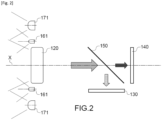
- FIG. 1 represents, in a perspective view, an example of an optical head according to the invention intended to equip a localized spraying system and the Figure 2 schematically represents the arrangement of some of its components.
- the spraying system is carried by an agricultural machine, for example a tractor or a trailer.
- the optical head 100 comprises a housing 110 inside which are housed a lens 120, a first optical sensor 130, a second optical sensor 140, a dichroic mirror 150, a first set 160 of light sources 161, a second set 170 of light sources 171 and a lighting control sub-unit 180.
- the optical sensors 130, 140, the dichroic mirror 150 and the lighting control sub-unit 180 are visible only in Figure 2 .
- the first optical sensor 130 is arranged to receive a portion of the light flux having passed through the objective 120 and generate a first sequence of images in three first spectral acquisition bands located within the visible spectrum, for example RGB bands.
- the second optical sensor 140 is arranged to receive another portion of the light flux having passed through the objective 120 and generate a second sequence of images in a second spectral acquisition band located within the near infrared spectrum.
- the images of each sequence are generated at acquisition times t acq separated two by two by a predetermined acquisition period ⁇ acq .
- the acquisition times are identical for the two sequences of images.
- the acquisition period makes it possible to define an acquisition frequency.
- the acquisition frequency is for example equal to 40 Hz.
- the light sources 171 are arranged to each emit a light beam along a main propagation axis parallel to the optical axis X, so as to form a second light beam.
- This second light beam is located in a second spectral illumination band covering the second spectral acquisition band.
- the light sources 161 generate uniform illumination suitable for the first optical sensor 130 and the light sources 171 generate uniform illumination suitable for the second optical sensor 140.
- the first and second light beams each have a main propagation axis coincident with the optical axis X. Consequently, the images generated by each optical sensor 130, 140 are devoid of shadow zones, in particular shadows usually observed by a point light source.
- the light sources 161, 171 are, for example, light-emitting diodes. According to the invention, the first assembly 160 makes it possible to form a first light beam of variable light intensity and the second assembly 170 makes it possible to form a second light beam of variable light intensity.
- the light intensities of the light beams are modified by the lighting control sub-unit 180.
- the lighting control sub-unit 180 is arranged to receive in real time the first sequence of images generated by the first optical sensor 130 and the second sequence of images generated by the second optical sensor 140, and to determine the light intensities of the first and second light beams to be emitted at each acquisition instant t acq .
- the intensity The light intensity of the first beam of light to be emitted at each given acquisition instant t acq is for example determined as a function of the image of the first sequence taken at the previous acquisition instant. More particularly, this light intensity can be determined as a function of a histogram of the light intensity levels of the pixels of the previous image.
- the light intensity of the second beam of light to be emitted at each acquisition instant t acq is for example determined as a function of the image of the second sequence taken at the previous acquisition instant, in particular a histogram of the light intensity levels of its pixels.
- the light intensity to be emitted by each set 160, 170 can be determined directly using the sum of the light intensity levels of the histogram and a look-up table.
- the light intensity is increased when the histogram is representative of underexposure, and decreased when the histogram is representative of overexposure.
- the light intensity of the first and second beams is not necessarily determined for each acquisition instant. It can be determined only for the instants at which the images used for the identification of the areas to be treated are taken.
- FIG. 3 schematically represents an agricultural machine equipped with a localized spraying system according to the invention.
- the agricultural machine 200 comprises a tractor 210 and a trailer 220.
- the localized spraying system 300 comprises a tank 310, a spray boom 320, a hydraulic circuit, not shown, a spray control unit 340, an image acquisition system 350 and a communication network 360.
- the trailer 220 carries the tank 310, the hydraulic circuit, the spray boom 320 and the image acquisition system 350.
- the tractor 210 could carry all of the elements of the spraying system 300.
- the tank 310 is arranged to contain a treatment product to be sprayed on the areas to be treated in a plot.
- the treatment product is, for example, a product biostimulation, for example a fertilizer or a product to stimulate the natural defenses of the cultivated plant, or a biocontrol product, for example a herbicide, an insecticide or a fungicide.
- the spray boom 320 extends along a transverse axis, orthogonal to an axis of advance of the agricultural machine 200, and comprises a plurality of spray sections 321. In the example of the Figure 3 , five spray sections are shown. However, the spray boom may comprise a much higher number of spray sections, for example several dozen.
- Each spray section 321 is individually connected to the tank 310 by the hydraulic circuit and comprises a distributor and a spray nozzle.
- Each distributor is connected to the spray control unit 340 via the communication network 360 and is controlled by this unit between at least one open position, in which circulation of the treatment product is possible from the tank 310 to the corresponding spray nozzle, and a closed position, in which said circulation is blocked.
- Each spray nozzle is arranged to spray treatment product onto an area of the plot. In particular, it is arranged to spray treatment product over a predetermined width, defined along the transverse axis.
- the image acquisition system 350 comprises a plurality of optical heads 100 as defined with reference to figures 1 And 2 .
- Each optical head 100 is connected to the spray control unit 340 via the communication network 360, so as to transfer all or part of the acquired images to it.
- the optical heads 100 are mounted on the spray boom 320 and are arranged so as to acquire images of contiguous areas of the plot. The imaged areas must be located upstream of the spray nozzles, so as to allow processing of the images by the spray control unit before the spray nozzles pass. It should be noted that the optical heads 100 could be mounted on a boom separate from the spray boom 320, for example at the front of the tractor 210.
- each optical head 100 integrates a lighting control sub-unit 180 adjusting the light intensities of its sets 160, 170 of light sources. These adjustments are thus carried out locally in each optical head.
- the lighting control sub-units 180 of the different optical heads can be considered collectively as forming a lighting control unit.
- the functions of the different sub-units can be grouped into a single hardware entity, also called a lighting control unit.
- the localized spraying system can comprise a central control interface making it possible to control the lighting control unit in an on mode, in which the lighting sources are switched on and their light intensity adjusted in accordance with the invention, and an off mode, in which the lighting sources remain switched off.
- the spray control unit 340 is arranged to determine, on the basis of the images acquired by the optical heads, whether a supply of treatment product is necessary for the imaged areas. According to a feature of the invention, not all of the images acquired by the optical sensor(s) are used to determine the areas to be treated.
- the images are for example used at a processing frequency of 10 Hz, which is generally sufficient to ensure continuity between the images along the axis of advance.
- the computational load is then reduced compared to taking into account all of the images in the sequence, for example at the acquisition frequency of 40 Hz.
- the analysis of the images can rely on different image processing algorithms. In particular, it can analyze the shape of the plants and their spectral properties (reflectance of the scene).
- the spray control unit 340 When treatment product is to be applied locally, the spray control unit 340 then controls the dispenser corresponding to the area to be treated in the open position, so that the corresponding spray nozzle delivers treatment product. On the other hand, when the application of treatment product is not necessary for an area covered by a spray nozzle, the spray control unit 340 controls the corresponding distributor into the closed position.
- FIG. 4 illustrates, by means of timing diagrams, an example of a timeline for image acquisition and processing with a view, on the one hand, to adjusting the light intensity(s) of the lighting sources and, on the other hand, to determining the areas of the plot to be processed.
- a first timing diagram represents the acquisition times t acq of the images of the sequence(s) generated in the different optical heads. As indicated previously, these acquisition times are preferably synchronized for all the optical heads. The successive acquisition times t acq are separated by an acquisition period ⁇ acq equal to 25 ms for an acquisition frequency of 40 Hz.
- a second timing diagram represents the adjustment times t ajust at which the images are used for adjusting the light intensities.
- a third timing diagram represents the processing times t trait at which the images are used to determine the areas of the plot on which the product must be sprayed. These processing times t trait are separated by a processing period ⁇ trait equal to 100 ms, corresponding to four times the acquisition period ⁇ acq .
- the timing diagrams of the Figure 4 illustrate the fact that, for each given processing instant t trait , corresponding to an acquisition instant t acq , the light intensity(s) to be emitted by the lighting sources are determined from the images acquired at the instant t ajust corresponding to the previous acquisition instant.
- the light intensities are determined with the same frequency as the processing frequency.
- the light intensities of the lighting sources can be determined at the image acquisition frequency. Consequently, at each acquisition of an image in an optical head, the light intensity of its lighting source is adjusted on the basis of the image acquired at the previous acquisition instant.
- the light intensity of a lighting source can be adjusted by the illumination intensity of each light source, the duty cycle between the illumination duration and the sum of the illumination and non-illumination durations, and/or the ratio of the number of illuminated light sources to the total number of light sources.
Landscapes
- Engineering & Computer Science (AREA)
- Life Sciences & Earth Sciences (AREA)
- Zoology (AREA)
- Insects & Arthropods (AREA)
- Pest Control & Pesticides (AREA)
- Wood Science & Technology (AREA)
- Environmental Sciences (AREA)
- Mechanical Engineering (AREA)
- Physics & Mathematics (AREA)
- General Physics & Mathematics (AREA)
- Multimedia (AREA)
- Theoretical Computer Science (AREA)
- Investigating Or Analysing Materials By Optical Means (AREA)
- Catching Or Destruction (AREA)
- Lenses (AREA)
Applications Claiming Priority (3)
| Application Number | Priority Date | Filing Date | Title |
|---|---|---|---|
| FR2109744A FR3126850B1 (fr) | 2021-09-16 | 2021-09-16 | Tête optique pour système agricole de pulvérisation localisée |
| EP21819540.2A EP4401539A1 (de) | 2021-09-16 | 2021-10-27 | Landwirtschaftliches punktsprühsystem mit eingebauter lichtquelle |
| PCT/FR2021/051886 WO2023041850A1 (fr) | 2021-09-16 | 2021-10-27 | Système agricole de pulvérisation localisée avec source d'éclairage intégrée |
Related Parent Applications (1)
| Application Number | Title | Priority Date | Filing Date |
|---|---|---|---|
| EP21819540.2A Division EP4401539A1 (de) | 2021-09-16 | 2021-10-27 | Landwirtschaftliches punktsprühsystem mit eingebauter lichtquelle |
Publications (2)
| Publication Number | Publication Date |
|---|---|
| EP4520170A2 true EP4520170A2 (de) | 2025-03-12 |
| EP4520170A3 EP4520170A3 (de) | 2025-05-28 |
Family
ID=78821347
Family Applications (2)
| Application Number | Title | Priority Date | Filing Date |
|---|---|---|---|
| EP21819540.2A Pending EP4401539A1 (de) | 2021-09-16 | 2021-10-27 | Landwirtschaftliches punktsprühsystem mit eingebauter lichtquelle |
| EP24215258.5A Pending EP4520170A3 (de) | 2021-09-16 | 2021-10-27 | Lokalisiertes landwirtschaftliches sprühsystem mit integrierter lichtquelle |
Family Applications Before (1)
| Application Number | Title | Priority Date | Filing Date |
|---|---|---|---|
| EP21819540.2A Pending EP4401539A1 (de) | 2021-09-16 | 2021-10-27 | Landwirtschaftliches punktsprühsystem mit eingebauter lichtquelle |
Country Status (6)
| Country | Link |
|---|---|
| US (1) | US20250295102A1 (de) |
| EP (2) | EP4401539A1 (de) |
| CN (1) | CN117940008A (de) |
| AU (1) | AU2021464747A1 (de) |
| FR (1) | FR3126850B1 (de) |
| WO (1) | WO2023041850A1 (de) |
Family Cites Families (9)
| Publication number | Priority date | Publication date | Assignee | Title |
|---|---|---|---|---|
| RU2129785C1 (ru) * | 1997-12-10 | 1999-05-10 | Всероссийский научно-исследовательский и проектно-технологический институт механизации и электрификации сельского хозяйства | Устройство для управляемой борьбы с сорняками |
| CN102591101A (zh) * | 2012-02-07 | 2012-07-18 | 广东美的电器股份有限公司 | 摄像头补光装置及其控制方法 |
| WO2016025848A1 (en) * | 2014-08-15 | 2016-02-18 | Monsanto Technology Llc | Apparatus and methods for in-field data collection and sampling |
| DE102014226189B4 (de) * | 2014-12-17 | 2017-08-24 | Continental Automotive Gmbh | Verfahren zur Ermittlung eines Unkrautanteils und Landtechnik-Steuereinrichtung |
| FR3057060B1 (fr) * | 2016-10-03 | 2019-12-20 | Tpl Vision Uk Ltd | Interface de commande pour dispositif d'eclairage de vision industrielle |
| EP3357332B1 (de) * | 2017-02-06 | 2022-04-13 | Bilberry Sas | Feldspritze |
| FR3063206B1 (fr) * | 2017-02-24 | 2021-08-13 | Bilberry Sas | Systeme de controle pour epandage agricole |
| BR112021003556A2 (pt) * | 2018-08-31 | 2021-05-18 | Faunaphotonics Agriculture & Environmental A/S | aparelho para pulverizar inseticidas |
| US20230079259A1 (en) * | 2020-02-20 | 2023-03-16 | Cropsy Technologies Limited | Tall plant health management system |
-
2021
- 2021-09-16 FR FR2109744A patent/FR3126850B1/fr active Active
- 2021-10-27 CN CN202180102356.4A patent/CN117940008A/zh active Pending
- 2021-10-27 EP EP21819540.2A patent/EP4401539A1/de active Pending
- 2021-10-27 WO PCT/FR2021/051886 patent/WO2023041850A1/fr not_active Ceased
- 2021-10-27 AU AU2021464747A patent/AU2021464747A1/en active Pending
- 2021-10-27 US US18/692,134 patent/US20250295102A1/en active Pending
- 2021-10-27 EP EP24215258.5A patent/EP4520170A3/de active Pending
Also Published As
| Publication number | Publication date |
|---|---|
| AU2021464747A1 (en) | 2024-03-07 |
| EP4401539A1 (de) | 2024-07-24 |
| FR3126850A1 (fr) | 2023-03-17 |
| EP4520170A3 (de) | 2025-05-28 |
| WO2023041850A1 (fr) | 2023-03-23 |
| US20250295102A1 (en) | 2025-09-25 |
| FR3126850B1 (fr) | 2024-06-14 |
| CN117940008A (zh) | 2024-04-26 |
Similar Documents
| Publication | Publication Date | Title |
|---|---|---|
| EP3998843B1 (de) | Pflanzenbehandlungssystem für landwirtschaftliche pflanzen | |
| KR102301658B1 (ko) | 식물 생육 장치 및 그 제어 방법 | |
| EP0373034B1 (de) | Verfahren und Vorrichtung zum programmierten Aufbringen eines Wirkstoffes auf die Bodenoberfläche | |
| US20220044044A1 (en) | Plant identification using heterogenous multi-spectral stereo imaging | |
| US11062481B2 (en) | Handheld device and method for determining a plant status | |
| WO1999032876A1 (fr) | Dispositif d'analyse non destructive de plantes et vehicule comportant un tel dispositif embarque | |
| FR3093620A1 (fr) | Procédé de réglage d’un paramètre d’un pulvérisateur agricole et pulvérisateur agricole pour sa mise en œuvre | |
| WO2019014703A1 (en) | 2D AND / OR 3D IMAGING DEVICE WITH ACTIVE LIGHTING FOR AGRICULTURE | |
| US20250178522A1 (en) | High intensity illumination system and methods of use thereof | |
| US11756136B2 (en) | Upward facing light sensor for plant detection | |
| CA2688260A1 (fr) | Appareil d'analyse de vegetaux sur le terrain, procede de suivi de l'etat ou de l'evolution d'une culture et procede de gestion d'un traitement de vegetaux | |
| FR3090270A1 (fr) | Procédé de distribution d’un produit, dispositif de commande et dispositif de pulvérisateur | |
| EP4152924A1 (de) | Verfahren und system zur steuerung einer landwirtschaftlichen behandlung | |
| EP3627210A1 (de) | Virtual-reality- oder augmented-reality-sichtsystem mit bildsensor des auges, und entsprechendes verfahren | |
| EP4520170A2 (de) | Lokalisiertes landwirtschaftliches sprühsystem mit integrierter lichtquelle | |
| JP3551264B2 (ja) | 植物活力変動の評価画像作成方法 | |
| CA3213067A1 (fr) | Systeme de traitement de plantes notamment en agriculture | |
| RU2844018C2 (ru) | Сельскохозяйственная система локализованного распыления со встроенным источником света | |
| EP4356729A1 (de) | Verfahren zur kalibrierung eines landwirtschaftlichen sprühgeräts | |
| CN114729990B (zh) | 用于园艺的飞行时间感测 | |
| JP2023180758A (ja) | 照明装置、撮像システム、及び評価方法 | |
| CN121889028A (zh) | 利用植物识别装置检测和处理植物的方法以及植物识别装置 | |
| EP3776078B1 (de) | Vorrichtung zur aufnahme von mehreren bildern jede mit anderer lichtbeleuchtung | |
| Esau et al. | Supplementary light source development for camera-based smart spraying in low light conditions | |
| EP4407301A1 (de) | Verfahren zur bestimmung der entwicklung von blattgregation |
Legal Events
| Date | Code | Title | Description |
|---|---|---|---|
| PUAI | Public reference made under article 153(3) epc to a published international application that has entered the european phase |
Free format text: ORIGINAL CODE: 0009012 |
|
| STAA | Information on the status of an ep patent application or granted ep patent |
Free format text: STATUS: THE APPLICATION HAS BEEN PUBLISHED |
|
| AC | Divisional application: reference to earlier application |
Ref document number: 4401539 Country of ref document: EP Kind code of ref document: P |
|
| AK | Designated contracting states |
Kind code of ref document: A2 Designated state(s): AL AT BE BG CH CY CZ DE DK EE ES FI FR GB GR HR HU IE IS IT LI LT LU LV MC MK MT NL NO PL PT RO RS SE SI SK SM TR |
|
| REG | Reference to a national code |
Ref country code: DE Ref legal event code: R079 Free format text: PREVIOUS MAIN CLASS: A01M0007000000 Ipc: A01B0069000000 |
|
| PUAL | Search report despatched |
Free format text: ORIGINAL CODE: 0009013 |
|
| AK | Designated contracting states |
Kind code of ref document: A3 Designated state(s): AL AT BE BG CH CY CZ DE DK EE ES FI FR GB GR HR HU IE IS IT LI LT LU LV MC MK MT NL NO PL PT RO RS SE SI SK SM TR |
|
| RIC1 | Information provided on ipc code assigned before grant |
Ipc: A01M 7/00 20060101ALI20250422BHEP Ipc: A01B 69/00 20060101AFI20250422BHEP |
|
| STAA | Information on the status of an ep patent application or granted ep patent |
Free format text: STATUS: REQUEST FOR EXAMINATION WAS MADE |
|
| 17P | Request for examination filed |
Effective date: 20251128 |