EP4518602A2 - Vehicle-mounted power supply apparatus and vehicle having same - Google Patents
Vehicle-mounted power supply apparatus and vehicle having same Download PDFInfo
- Publication number
- EP4518602A2 EP4518602A2 EP25152126.6A EP25152126A EP4518602A2 EP 4518602 A2 EP4518602 A2 EP 4518602A2 EP 25152126 A EP25152126 A EP 25152126A EP 4518602 A2 EP4518602 A2 EP 4518602A2
- Authority
- EP
- European Patent Office
- Prior art keywords
- vehicle
- fixing
- power supply
- skeleton
- supply apparatus
- Prior art date
- Legal status (The legal status is an assumption and is not a legal conclusion. Google has not performed a legal analysis and makes no representation as to the accuracy of the status listed.)
- Pending
Links
Images




Classifications
-
- H—ELECTRICITY
- H05—ELECTRIC TECHNIQUES NOT OTHERWISE PROVIDED FOR
- H05K—PRINTED CIRCUITS; CASINGS OR CONSTRUCTIONAL DETAILS OF ELECTRIC APPARATUS; MANUFACTURE OF ASSEMBLAGES OF ELECTRICAL COMPONENTS
- H05K7/00—Constructional details common to different types of electric apparatus
- H05K7/20—Modifications to facilitate cooling, ventilating, or heating
- H05K7/2089—Modifications to facilitate cooling, ventilating, or heating for power electronics, e.g. for inverters for controlling motor
- H05K7/20927—Liquid coolant without phase change
-
- H—ELECTRICITY
- H05—ELECTRIC TECHNIQUES NOT OTHERWISE PROVIDED FOR
- H05K—PRINTED CIRCUITS; CASINGS OR CONSTRUCTIONAL DETAILS OF ELECTRIC APPARATUS; MANUFACTURE OF ASSEMBLAGES OF ELECTRICAL COMPONENTS
- H05K9/00—Screening of apparatus or components against electric or magnetic fields
- H05K9/0007—Casings
- H05K9/002—Casings with localised screening
- H05K9/0022—Casings with localised screening of components mounted on printed circuit boards [PCB]
- H05K9/0024—Shield cases mounted on a PCB, e.g. cans or caps or conformal shields
-
- B—PERFORMING OPERATIONS; TRANSPORTING
- B60—VEHICLES IN GENERAL
- B60R—VEHICLES, VEHICLE FITTINGS, OR VEHICLE PARTS, NOT OTHERWISE PROVIDED FOR
- B60R16/00—Electric or fluid circuits specially adapted for vehicles and not otherwise provided for; Arrangement of elements of electric or fluid circuits specially adapted for vehicles and not otherwise provided for
- B60R16/02—Electric or fluid circuits specially adapted for vehicles and not otherwise provided for; Arrangement of elements of electric or fluid circuits specially adapted for vehicles and not otherwise provided for electric constitutive elements
-
- H—ELECTRICITY
- H01—ELECTRIC ELEMENTS
- H01F—MAGNETS; INDUCTANCES; TRANSFORMERS; SELECTION OF MATERIALS FOR THEIR MAGNETIC PROPERTIES
- H01F27/00—Details of transformers or inductances, in general
- H01F27/02—Casings
- H01F27/025—Constructional details relating to cooling
-
- H—ELECTRICITY
- H01—ELECTRIC ELEMENTS
- H01F—MAGNETS; INDUCTANCES; TRANSFORMERS; SELECTION OF MATERIALS FOR THEIR MAGNETIC PROPERTIES
- H01F27/00—Details of transformers or inductances, in general
- H01F27/06—Mounting, supporting or suspending transformers, reactors or choke coils not being of the signal type
-
- H—ELECTRICITY
- H01—ELECTRIC ELEMENTS
- H01F—MAGNETS; INDUCTANCES; TRANSFORMERS; SELECTION OF MATERIALS FOR THEIR MAGNETIC PROPERTIES
- H01F27/00—Details of transformers or inductances, in general
- H01F27/24—Magnetic cores
-
- H—ELECTRICITY
- H01—ELECTRIC ELEMENTS
- H01F—MAGNETS; INDUCTANCES; TRANSFORMERS; SELECTION OF MATERIALS FOR THEIR MAGNETIC PROPERTIES
- H01F27/00—Details of transformers or inductances, in general
- H01F27/28—Coils; Windings; Conductive connections
- H01F27/2847—Sheets; Strips
- H01F27/2852—Construction of conductive connections, of leads
-
- H—ELECTRICITY
- H01—ELECTRIC ELEMENTS
- H01F—MAGNETS; INDUCTANCES; TRANSFORMERS; SELECTION OF MATERIALS FOR THEIR MAGNETIC PROPERTIES
- H01F27/00—Details of transformers or inductances, in general
- H01F27/28—Coils; Windings; Conductive connections
- H01F27/30—Fastening or clamping coils, windings, or parts thereof together; Fastening or mounting coils or windings on core, casing, or other support
- H01F27/306—Fastening or mounting coils or windings on core, casing or other support
-
- H—ELECTRICITY
- H05—ELECTRIC TECHNIQUES NOT OTHERWISE PROVIDED FOR
- H05K—PRINTED CIRCUITS; CASINGS OR CONSTRUCTIONAL DETAILS OF ELECTRIC APPARATUS; MANUFACTURE OF ASSEMBLAGES OF ELECTRICAL COMPONENTS
- H05K7/00—Constructional details common to different types of electric apparatus
- H05K7/20—Modifications to facilitate cooling, ventilating, or heating
- H05K7/20218—Modifications to facilitate cooling, ventilating, or heating using a liquid coolant without phase change in electronic enclosures
- H05K7/20272—Accessories for moving fluid, for expanding fluid, for connecting fluid conduits, for distributing fluid, for removing gas or for preventing leakage, e.g. pumps, tanks or manifolds
-
- H—ELECTRICITY
- H05—ELECTRIC TECHNIQUES NOT OTHERWISE PROVIDED FOR
- H05K—PRINTED CIRCUITS; CASINGS OR CONSTRUCTIONAL DETAILS OF ELECTRIC APPARATUS; MANUFACTURE OF ASSEMBLAGES OF ELECTRICAL COMPONENTS
- H05K7/00—Constructional details common to different types of electric apparatus
- H05K7/20—Modifications to facilitate cooling, ventilating, or heating
- H05K7/20845—Modifications to facilitate cooling, ventilating, or heating for automotive electronic casings
- H05K7/20872—Liquid coolant without phase change
-
- H—ELECTRICITY
- H05—ELECTRIC TECHNIQUES NOT OTHERWISE PROVIDED FOR
- H05K—PRINTED CIRCUITS; CASINGS OR CONSTRUCTIONAL DETAILS OF ELECTRIC APPARATUS; MANUFACTURE OF ASSEMBLAGES OF ELECTRICAL COMPONENTS
- H05K9/00—Screening of apparatus or components against electric or magnetic fields
- H05K9/0007—Casings
- H05K9/002—Casings with localised screening
- H05K9/0022—Casings with localised screening of components mounted on printed circuit boards [PCB]
- H05K9/0037—Housings with compartments containing a PCB, e.g. partitioning walls
-
- H—ELECTRICITY
- H01—ELECTRIC ELEMENTS
- H01F—MAGNETS; INDUCTANCES; TRANSFORMERS; SELECTION OF MATERIALS FOR THEIR MAGNETIC PROPERTIES
- H01F27/00—Details of transformers or inductances, in general
- H01F27/06—Mounting, supporting or suspending transformers, reactors or choke coils not being of the signal type
- H01F2027/065—Mounting on printed circuit boards
-
- H—ELECTRICITY
- H01—ELECTRIC ELEMENTS
- H01F—MAGNETS; INDUCTANCES; TRANSFORMERS; SELECTION OF MATERIALS FOR THEIR MAGNETIC PROPERTIES
- H01F27/00—Details of transformers or inductances, in general
- H01F27/28—Coils; Windings; Conductive connections
- H01F27/29—Terminals; Tapping arrangements for signal inductances
-
- H—ELECTRICITY
- H01—ELECTRIC ELEMENTS
- H01F—MAGNETS; INDUCTANCES; TRANSFORMERS; SELECTION OF MATERIALS FOR THEIR MAGNETIC PROPERTIES
- H01F27/00—Details of transformers or inductances, in general
- H01F27/28—Coils; Windings; Conductive connections
- H01F27/29—Terminals; Tapping arrangements for signal inductances
- H01F27/292—Surface mounted devices
-
- Y—GENERAL TAGGING OF NEW TECHNOLOGICAL DEVELOPMENTS; GENERAL TAGGING OF CROSS-SECTIONAL TECHNOLOGIES SPANNING OVER SEVERAL SECTIONS OF THE IPC; TECHNICAL SUBJECTS COVERED BY FORMER USPC CROSS-REFERENCE ART COLLECTIONS [XRACs] AND DIGESTS
- Y02—TECHNOLOGIES OR APPLICATIONS FOR MITIGATION OR ADAPTATION AGAINST CLIMATE CHANGE
- Y02T—CLIMATE CHANGE MITIGATION TECHNOLOGIES RELATED TO TRANSPORTATION
- Y02T10/00—Road transport of goods or passengers
- Y02T10/60—Other road transportation technologies with climate change mitigation effect
- Y02T10/70—Energy storage systems for electromobility, e.g. batteries
-
- Y—GENERAL TAGGING OF NEW TECHNOLOGICAL DEVELOPMENTS; GENERAL TAGGING OF CROSS-SECTIONAL TECHNOLOGIES SPANNING OVER SEVERAL SECTIONS OF THE IPC; TECHNICAL SUBJECTS COVERED BY FORMER USPC CROSS-REFERENCE ART COLLECTIONS [XRACs] AND DIGESTS
- Y02—TECHNOLOGIES OR APPLICATIONS FOR MITIGATION OR ADAPTATION AGAINST CLIMATE CHANGE
- Y02T—CLIMATE CHANGE MITIGATION TECHNOLOGIES RELATED TO TRANSPORTATION
- Y02T10/00—Road transport of goods or passengers
- Y02T10/60—Other road transportation technologies with climate change mitigation effect
- Y02T10/7072—Electromobility specific charging systems or methods for batteries, ultracapacitors, supercapacitors or double-layer capacitors
-
- Y—GENERAL TAGGING OF NEW TECHNOLOGICAL DEVELOPMENTS; GENERAL TAGGING OF CROSS-SECTIONAL TECHNOLOGIES SPANNING OVER SEVERAL SECTIONS OF THE IPC; TECHNICAL SUBJECTS COVERED BY FORMER USPC CROSS-REFERENCE ART COLLECTIONS [XRACs] AND DIGESTS
- Y02—TECHNOLOGIES OR APPLICATIONS FOR MITIGATION OR ADAPTATION AGAINST CLIMATE CHANGE
- Y02T—CLIMATE CHANGE MITIGATION TECHNOLOGIES RELATED TO TRANSPORTATION
- Y02T90/00—Enabling technologies or technologies with a potential or indirect contribution to GHG emissions mitigation
- Y02T90/10—Technologies relating to charging of electric vehicles
- Y02T90/14—Plug-in electric vehicles
Definitions
- the present disclosure relates to the field of vehicle technologies, and specifically to a vehicle-mounted power supply apparatus and a vehicle having same.
- the internal structure of the vehicle-mounted power supply is more complex and is prone to interference by external signals, reducing the operating efficiency of the vehicle-mounted power supply.
- the present disclosure aims to resolve at least one of the technical problems in the related art. Therefore, the present disclosure proposes a vehicle-mounted power supply apparatus.
- the vehicle-mounted power supply apparatus is characterized by simple structure, good heat dissipation and high operating efficiency.
- the present disclosure further provides a vehicle.
- the vehicle includes the vehicle-mounted power supply apparatus.
- a vehicle-mounted power supply apparatus includes: a housing, a magnetic device, and a shielding component.
- a mounting position is arranged in the housing.
- the magnetic device is an integrated part and is arranged at the mounting position.
- the shielding component is arranged in the housing, and the shielding component surrounds a periphery of the mounting position.
- the integrated design of the magnetic device can be easily realized by mounting the magnetic device at the mounting position, and then the shielding component is used to protect the magnetic device to shield the interference of external signals, thereby improving the stability and safety of the operation of the vehicle-mounted power supply apparatus.
- a coolant channel is defined in the shielding component, and the coolant channel surrounds a periphery of the magnetic device.
- the shielding component includes: a liquid passage member and a shielding wall.
- the coolant channel is defined in the liquid passage member.
- the shielding wall is separated from the liquid passage member, and the shielding wall is located on a side of the liquid passage member away from the magnetic device.
- one side of the coolant channel is provided with an open opening; and the shielding component further includes: a liquid passage cover plate and a sealing ring.
- the liquid passage cover plate is hermetically connected with the liquid passage member to close the open opening.
- the sealing ring is sandwiched between the liquid passage cover plate and the liquid passage member.
- the liquid passage member includes a first sidewall and a second sidewall separated from the first sidewall, the coolant channel is defined between the first sidewall and the second sidewall, the first sidewall faces toward the magnetic device, the second sidewall is located on a side of the first sidewall away from the magnetic device, and a distance between the first sidewall and the second sidewall gradually decreases in a direction toward the open opening.
- the vehicle-mounted power supply apparatus further includes: a circuit board, a plurality of power switch tubes, and a fixing apparatus.
- Each of the power switch tubes is respectively electrically connected with the circuit board.
- the fixing apparatus is configured for simultaneously fixing the plurality of power switch tubes between the liquid passage member and the shielding wall.
- the fixing apparatus includes: a fixing plate and a plurality of elastic pieces.
- Each of the elastic pieces is configured for fixing one power switch tube.
- One end of each of the elastic pieces is fixed to the fixing plate, and the other end of each of the elastic pieces is located at one side of the fixing plate in a thickness direction and is separated from a surface on the one side of the fixing plate in the thickness direction.
- each of the elastic pieces includes: a fixing segment, a connection segment, and a pressing segment.
- the fixing segment is fixed on the fixing plate.
- the connection segment is connected between the fixing segment and the pressing segment.
- the pressing segment includes a first pressing portion and a second pressing portion. One end of the first pressing portion is connected with the connection segment, and an other end of the first pressing portion extends away from the fixing plate.
- One end of the second pressing portion is connected with the other end of the first pressing portion, and an other end of the second pressing portion extends toward the fixing plate.
- At least one boss is arranged on an other side of the fixing plate in the thickness direction, and a cross-sectional area of the boss gradually decreases in a direction away from the fixing plate; and the boss is formed by a part of the surface on the one side of the fixing plate in the thickness direction protruding toward a surface on the other side of the fixing plate in the thickness direction.
- an edge of the fixing plate is provided with at least one pull lug extending away from a center of the fixing plate; the fixing apparatus further includes: at least one pull lug piece, where the pull lug piece is arranged on one side of the pull lug in a thickness direction; and an edge of the fixing plate is provided with at least one fixing lug, and a free end of the fixing lug extends toward the other side of the fixing plate along the thickness direction of the fixing plate.
- the magnetic device includes: a magnetic core, a coil, a skeleton, a wire nose, and a nut.
- the coil is wound on the magnetic core and has a pin.
- the skeleton is arranged on the magnetic core.
- the wire nose is mounted on the skeleton and connected with the pin, and the wire nose has a connecting hole.
- the nut is mounted on the skeleton, and the nut has a threaded hole corresponding to a position of the connecting hole.
- the wire nose is movably mounted on the skeleton to make a distance between the connecting hole and the skeleton adjustable; and the wire nose includes: a plate portion, a bending portion, and a clamping portion.
- the connecting hole is formed in the plate portion, and the nut is arranged between the plate portion and the skeleton.
- One end of the bending portion is connected to the plate portion, the bending portion protrudes toward the skeleton, the bending portion is movably mounted on the skeleton, and the bending portion is configured as a U shape protruding toward the skeleton to form a groove.
- the clamping portion is connected to the other end of the bending portion and clamps the pin, and the clamping portion is located in the groove.
- the skeleton is provided with an anti-rotation groove
- the nut is arranged in the anti-rotation groove, and a distance between the plate portion and a bottom wall of the anti-rotation groove is greater than an axial length of the nut.
- the wire nose further includes: a positioning protrusion, where the positioning protrusion and the bending portion are respectively connected to two opposite side edges of the plate portion, the skeleton is provided with a positioning groove, and the positioning protrusion is engaged with the positioning groove.
- the vehicle-mounted power supply apparatus further includes: a magnetic circuit piece and at least one magnetic sheet.
- the magnetic core and the skeleton are carried on the magnetic circuit piece.
- the magnetic sheet is mounted on the skeleton, the magnetic sheet and the magnetic circuit piece are respectively arranged on two opposite sides of the magnetic core, the skeleton is provided with a hook, and the hook is hooked to an edge of the magnetic sheet.
- a vehicle according to an embodiment of the present disclosure includes the vehicle-mounted power supply apparatus described above.
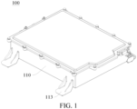
- a vehicle-mounted power supply apparatus 100 according to an embodiment of the present disclosure will be described below with reference to FIG. 1 to FIG. 5 , which includes: a housing 110, a magnetic device 120, and a shielding component 130.
- a mounting position 111 is arranged in the housing 110, and the magnetic device 120 is an integrated part and is arranged at the mounting position 111. It should be noted herein that by arranging the mounting position 111 inside the housing 110, the magnetic device 120 may be centrally arranged at the mounting position 111, thereby improving the integration degree of the vehicle-mounted power supply apparatus 100.
- the shielding component 130 is arranged in the housing 110, and the shielding component 130 surrounds a periphery of the mounting position 111. The shielding component 130 can be used to shield electromagnetic signals, thereby protecting the magnetic device 120.
- the integrated design of the magnetic device 120 can be easily realized by mounting the magnetic device 120 at the mounting position 111, and then the shielding component 130 is used to protect the magnetic device 120 to shield the interference of external signals, thereby improving the stability and safety of the operation of the vehicle-mounted power supply apparatus 100.
- a coolant channel 131 is defined in the shielding component 130, and the coolant channel 131 surrounds a periphery of the magnetic device 120.
- the coolant channel 131 may be provided therein with a coolant.
- the coolant flows, heat exchange occurs between the coolant near the magnetic device 120 and the magnetic device 120, that is, the coolant can cool the magnetic device 120.
- the flow of the coolant can take away heat generated by the magnetic device 120, so as to cool and dissipate heat from the magnetic device 120.
- the coolant channel 131 By arranging the coolant channel 131 to surround the periphery of the magnetic device 120, the coolant channel 131 can be close to more positions on the magnetic device 120, thereby improving the cooling efficiency of the coolant channel 131.
- the shielding component 130 may include: a liquid passage member 132 and a shielding wall 133.
- the coolant channel 131 is defined in the liquid passage member 132.
- the shielding wall 133 is separated from the liquid passage member 132, and the shielding wall 133 is located on a side of the liquid passage member 132 away from the magnetic device 120. It can be understood that, the liquid passage member 132 is closer to the magnetic device 120 than the shielding wall 133 is, that is, the liquid passage member 132 is arranged adjacent to the magnetic device 120, thereby facilitating the cooling of the magnetic device 120 by the coolant channel 131.
- the shielding wall 133 By arranging the shielding wall 133 around the liquid passage member 132, the magnetic device 120 and the liquid passage member 132 can be protected at the same time.
- the liquid passage member 132 may include a first segment 1321 and a second segment 1322 separated from the first segment 1321, and the magnetic device 120 is sandwiched between the first segment 1321 and the second segment 1322. It can be understood that the first segment 1321 is located on one side of the magnetic device 120, and the second segment 1322 is located on the other side of the magnetic device 120, so as to dissipate heat from the magnetic device 120 from multiple directions.
- the liquid passage member 132 arranged on two sides of the magnetic device 120 can limit the magnetic device 120, thereby improving the assembly stability of the magnetic device 120.
- one side of the coolant channel 131 is provided with an open opening
- the shielding component 130 further includes: a liquid passage cover plate 134.
- the liquid passage cover plate 134 is hermetically connected with the liquid passage member 132 to close the open opening. Therefore, on the one hand, it is convenient to fill the coolant into the coolant channel 131.
- the liquid passage cover plate 134 can be used to seal the open opening, thereby simplifying the structure of the liquid passage member 132 and facilitating the replacement and maintenance of the liquid passage member 132.
- the liquid passage cover plate 134 is welded to the liquid passage member 132, or the liquid passage cover plate 134 is connected to the liquid passage member 132 by a screw. In this way, the liquid passage cover plate 134 and the liquid passage member 132 can be fixed by welding or by bolt connection.
- a coolant with high heat exchange effect may be used to extend the heat dissipation effect of the liquid passage member 132, and at the same time, the liquid passage member 132 can also have higher stability and avoid coolant leakage.
- the coolant that exchanges heat in the coolant channel 131 has a higher use effect, thereby increasing the heat dissipation effect of the liquid passage member 132.
- the liquid passage cover plate 134 and the liquid passage member 132 connected by a bolt have good detachable performance, which not only improves the assembly efficiency of the liquid passage member 132, but also facilitates the disassembly of the liquid passage member 132. This improves the assembly and disassembly efficiency of the liquid passage member 132, and facilitates the use, maintenance and repair of the vehicle-mounted power supply apparatus 100.
- the shielding component 130 further includes: a sealing ring 135.
- the sealing ring 135 is sandwiched between the liquid passage cover plate 134 and the liquid passage member 132. Therefore, the sealing ring 135 arranged between the liquid passage cover plate 134 and the liquid passage member 132 provides a better sealing performance for the coolant channel 131 on the liquid passage member 132, which can further avoid liquid leakage and other situations, and further increase the usage reliability of the coolant channel 131.
- the sealing ring 135 sandwiched between the liquid passage cover plate 134 and the liquid passage member 132 can facilitate the assembly of the liquid passage cover plate 134 and improve the assembly efficiency of the liquid passage cover plate 134.
- the sealing ring 135 can reduce the adhesion resistance between the liquid passage cover plate 134 and the liquid passage member 132, so that the disassembly convenience of the liquid passage cover plate 134 can be improved, thereby further facilitating the use, maintenance and repair of the vehicle-mounted power supply apparatus 100.
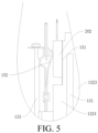
- the liquid passage member 132 may include a first sidewall 1323 and a second sidewall 1324 separated from the first sidewall 1323.
- the coolant channel 131 is defined between the first sidewall 1323 and the second sidewall 1324.
- the first sidewall 1323 faces toward the magnetic device 120.
- the second sidewall 1324 is located on a side of the first sidewall 1323 away from the magnetic device 120.
- a distance between the first sidewall 1323 and the second sidewall 1324 gradually decreases in a direction toward the open opening.
- the coolant channel 131 is defined to be narrow in the upper part and wide in the lower part, so as to facilitate the demolding of the liquid passage member 132 and improve the yield of the liquid passage member 132.
- the first sidewall 1323 facing toward the magnetic device 120 can better exchange heat with the magnetic device 120 to improve the cooling efficiency of the liquid passage member 132, thereby improving the operating efficiency of the vehicle-mounted power supply apparatus 100.
- the vehicle-mounted power supply apparatus 100 further includes: a circuit board (not shown), power switch tubes 202, and a fixing apparatus.
- the power switch tubes 202 are electrically connected with the circuit board.
- the power switch tubes 202 are arranged between the liquid passage member 132 and the shielding wall 133.
- the fixing apparatus 152 is configured for simultaneously fixing a plurality of power switch tubes 202 between the liquid passage member 132 and the shielding wall 133.
- the power switch tubes 202 can control on/off of a circuit on the circuit board. Therefore, the arrangement of the power switch tubes 202 on the shielding wall 133 can not only enable the shielding wall 133 to better support the power switch tubes 202 and enable the power switch tubes 202 to better control on/off of the circuit on the circuit board, but also enable the shielding wall 133 to shield the interference of external signals on the power switch tubes 202, allowing the power switch tubes 202 to more precisely control the circuit board.
- the fixing apparatus 152 is further arranged on an outer side of the power switch tube 202.
- the fixing apparatus 152 has a function of press-fitting the power switch tube 202.
- the fixing apparatus 152 deforms during the press-fit process, and the deformed fixing apparatus 152 has axial pressure, which sticks the power switch tube 202 and the liquid passage member 132 together, thereby providing the power switch tube 202 with high stability.
- the fixing apparatus 152 after the fixing apparatus 152 is arranged to fix the power switch tube 202, the fixing apparatus 152 also has good heat exchange capacity, so that the heat generated by the power switch tube 202 during operation can be transferred through the fixing apparatus 152, to lower the operating temperature of the power switch tube 202 and improve the operating efficiency of the power switch tube 202.
- the fixing apparatus 152 can fix a plurality of power switch tubes 202 at a time, achieving high fixing efficiency.
- the fixing process of the fixing apparatus 152 can also be simplified to improve the assembly efficiency of the vehicle-mounted power supply apparatus 100.
- the fixing apparatus 152 for power switch tubes 202 will be described below with reference to FIG. 11 to FIG. 15 .
- the fixing apparatus 152 fixes the power switch tube 202 to the liquid passage member 132 of the shielding component 130.
- the power switch tube 202 is bonded with the second sidewall 1324, so that the fixing apparatus 152 squeezes the power switch tube 202 to the second sidewall 1324.
- the second sidewall 1324 provides support for the power switch tube 202.
- the power switch tube 202 can transfer the heat generated during operation to the second sidewall 1324 to reduce the operating temperature of the power switch tube 202 and improve the operating efficiency of the power switch tube 202.
- the first sidewall 1323 of the liquid passage member 132 is located at the side away from the power switch tube 202, and can absorb the heat emitted by the magnetic device 120 during operation.
- the shielding component 130 further includes the shielding wall 133.
- the shielding wall 133 is located on the other side away from the power switch tube 202 and can shield external interference signals, including interference signals to the power switch tube 202 and interference signals to the magnetic device 120 inside the power switch tube 202.
- This embodiment only introduces the bonding and interaction of the power switch tube 202 with the second sidewall 1324 under the action of the fixing apparatus 152.
- the first sidewall 1323 and the shielding wall 133 have been introduced in the context, and will not be repeated here.
- the fixing apparatus 152 for power switch tubes 202 includes a fixing plate 1 and a plurality of elastic pieces 2.
- each elastic piece 2 is used to fix one power switch tube 202, and one end of each elastic piece 2 (for example, a lower end in FIG. 11 ) is fixed to the fixing plate 1. In this case, the one end of each elastic piece 2 is fixed relative to the fixing plate 1.
- the other end of each elastic piece 2 (for example, an upper end in FIG. 11 ) is located on one side of the fixing plate 1 in the thickness direction, and the other end of each elastic piece 2 is separated from a surface on the one side of the fixing plate 1 in the thickness direction.
- the other end of the plurality of elastic pieces 2 can move toward the fixing plate 1 under the action of the corresponding power switch tube 202, and due to an elastic force of the elastic piece 2 itself, the other end of the plurality of elastic pieces 2 can respectively apply a force toward the second sidewall 1324 to the corresponding power switch tube 202, thereby tightly pressing the plurality of power switch tubes 202 onto the second sidewall 1324.
- This enables the plurality of power switch tubes 202 to closely fit with the second sidewall 1324, thereby realizing effective heat dissipation for the plurality of power switch tubes 202 and prolonging the service life of the plurality of power switch tubes 202.
- the fixing apparatus 152 including the fixing plate 1 and the plurality of elastic pieces 2 is an integral structure, which can press-fit a plurality of power switch tubes 202 at a time, thereby simplifying the assembly process, improving the assembly efficiency, and facilitating subsequent disassembly.
- the disassembly can be done at a time.
- the fixing apparatus 152 for power switch tubes 202 include the fixing plate 1 and the plurality of elastic pieces 2, where one end of each elastic piece 2 is fixed to the fixing plate 1, the other end of each elastic piece 2 is located on one side of the fixing plate 1 in the thickness direction and is separated from the surface on the one side of the fixing plate 1 in the thickness direction.
- the fixing apparatus 152 has a simple structure. When the fixing apparatus 152 is applied to the switch tube assembly 200, the assembly efficiency of the fixing apparatus 152 is high.
- each elastic piece 2 includes a fixing segment 21, a pressing segment 23, and a connection segment 22.
- the fixing segment 21 is fixed on the fixing plate 1, and each elastic piece 2 is fixedly connected to the fixing plate 1 through the fixing segment 21.
- the pressing segment 23 is located on the one side of the fixing plate 1 in the thickness direction, and the pressing segment 23 is separated from the surface on the one side of the fixing plate 1 in the thickness direction.
- each elastic piece 2 can tightly press the corresponding power switch tube 202 through the pressing segment 23 to fit with the inner wall of the shielding component 130, such as the second sidewall 1324.
- the connection segment 22 is connected between the fixing segment 21 and the pressing segment 23. In this way, it can be effectively ensured that each elastic piece 2 has sufficient elasticity, so that the power switch tube 202 can be reliably and tightly pressed in the shielding component 130.
- the pressing segment 23 includes a first pressing portion 231 and a second pressing portion 232.
- One end of the first pressing portion 231 (for example, a lower end in FIG. 11 ) is connected with the connection segment 22, and the other end of the first pressing portion 231 (for example, an upper end in FIG. 11 ) extends away from the fixing plate 1.
- One end of the second pressing portion 232 (for example, a lower end in FIG. 11 ) is connected with the other end of the first pressing portion 231, and the other end of the second pressing portion 232 (for example, an upper end in FIG. 11 ) extends toward the fixing plate 1.
- the connection between the first pressing portion 231 and the second pressing portion 232 is suitable for stopping with the power switch tube 202.
- the fixing apparatus 152 can be more smoothly mounted into the shielding component 130, and the end of the pressing segment 23 is not easy to contact the power switch tube 202 directly, thereby extending the service life of the power switch tube 202.
- a length of the second pressing portion 232 may be less than that of the first pressing portion 231, to save materials while ensuring that the pressing portion has a sufficient force on the power switch tube 202, thereby reducing the costs.
- an angle between the first pressing portion 231 and the fixing plate 1 is greater than an angle between the connection segment 22 and the fixing plate 1.
- an inclination angle of the first pressing portion 231 is greater, and there may be a smooth transition at the connection between the first pressing portion 231 and the connection segment 22.
- the plurality of elastic pieces 2 constitute at least one elastic piece group.
- the elastic piece group includes at least two elastic pieces 2 arranged side by side. One end of each of the at least two elastic pieces 2 is fixed to the fixing plate 1, and the other ends of the at least two elastic pieces 2 are separated from each other. Such arrangement is convenient for processing and can reduce the costs.
- FIG. 11 and FIG. 12 seven elastic piece groups are shown. The seven elastic piece groups are arranged at intervals along a length direction of the fixing plate 1. Each elastic piece group includes two elastic pieces 2 arranged along the length direction of the fixing plate 1. Lower ends of the two elastic pieces 2 are connected, and upper ends of the two elastic pieces 2 are separated from each other for respectively stopping with the corresponding power switch tubes 202.
- the at least two elastic pieces 2 in each elastic piece group may be integrally formed.
- the seven elastic piece groups shown in FIG. 11 and FIG. 12 may include three first elastic piece groups and four second elastic piece groups.
- the length and width of the elastic piece 2 in each first elastic piece group may be different from the length and width of the elastic piece 2 in each second elastic piece group, so as to adapt to power switch tubes 202 of different sizes.
- each elastic piece 2 may be riveted (as shown in FIG. 11 and FIG. 12 ), welded (not shown) or threadedly connected (not shown) to the fixing plate 1. Therefore, the production process is simple.
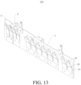
- the present disclosure is not limited thereto, and the plurality of elastic pieces 2 may also be integrally formed with the fixing plate 1, as shown in FIG. 13 .
- the plurality of elastic pieces 2 may be formed from the fixing plate 1 by stamping.
- At least one boss 4 is arranged on the other side of the fixing plate 1 in the thickness direction.
- the boss 4 protrudes from the surface on the other side of the fixing plate 1 in the thickness direction.
- the boss 4 stops against the shielding wall 133 opposite to the second sidewall 1324 in the shielding component 130.
- the boss 4 can be engaged with the elastic piece 2, so that the elastic piece 2 can exert a greater force on the power switch tube 202, so that the power switch tube 202 can be more closely fit to the second sidewall 1324 of the shielding component 130.
- a cross-sectional area of the boss 4 gradually decreases in a direction away from the fixing plate 1.
- at least one side surface of the boss 4 may be formed as a chamfer 121, for example, at least a lower side surface of the boss 4 may be formed as a chamfer 121, so that the fixing apparatus 152 can be more smoothly assembled into the shielding component 130.
- the boss 4 may be formed by a part of the surface on the one side of the fixing plate 1 in the thickness direction protruding toward a surface on the other side of the fixing plate 1 in the thickness direction.
- the boss 4 may be formed by stamping to simplify the fabrication process of the boss 4 and reduce the costs.
- the boss 4 may also be a solid structure arranged on the surface of the other side of the fixing plate 1 in the thickness direction.
- a plurality of bosses 4 may be arranged, and the plurality of bosses 4 are arranged at intervals along the arrangement direction of the plurality of elastic pieces 2. Therefore, the arrangement of the plurality of bosses 4 can effectively ensure that the plurality of elastic pieces respectively exert a large force on the corresponding power switch tubes 202. It can be understood that the number of bosses 4 may be less than the number of elastic pieces 2, as long as it can ensure that the plurality of elastic pieces 2 can tightly press the corresponding power switch tubes 202 in the shielding component 130.
- an edge of the fixing plate 1 is provided with at least one pull lug 5 extending away from a center of the fixing plate 1.
- at least one pull lug 5 extending away from a center of the fixing plate 1.
- two pull lugs 5 are shown, and the two pull lugs 5 may be in the same plane with the fixing plate 1.
- operation personnel may hold the two pull lugs 5 and insert the fixing apparatus 152 into the shielding component 130 from top to bottom, so that the plurality of elastic pieces 2 can closely fit with the second sidewall 1324 of the shielding component 130.
- the two pull lugs 5 may be pulled upward, so that the fixing apparatus 152 can be conveniently pulled out. Therefore, the assembly and disassembly of the fixing apparatus 152 can be more conveniently realized by arranging the pull lug 5.
- the two pull lugs 5 shown in FIG. 11 to FIG. 12 are for the purpose of illustration. After reading the technical solution of the present disclosure, those of ordinary skill in the art can obviously understand that the application of this solution to technical solutions involving three or more pull lugs 5 also falls within the scope of protection of the present disclosure.
- the fixing apparatus 152 may include at least one pull lug piece 51.
- the pull lug piece 51 is arranged on one side of the pull lug 5 in a thickness direction.
- the pull lug piece 51 may include a first segment and a second segment connected with each other, a length of the first segment of the pull lug piece 51 may be equal to a length of the pull lug 5, a width of the first segment of the pull lug piece 51 may be equal to a width of the pull lug 5, and a width of the second segment may be greater than the width of the first segment.
- the first segment of the pull lug piece 51 may correspond to the pull lug 5, and the second segment of the pull lug piece 51 may be fixed to the fixing plate 1 by riveting or welding. Therefore, the pull lug 5 can be reinforced by arranging the pull lug piece 51, thereby improving the structural strength of the pull lug 5.
- the number of pull lug pieces 51 may be equal to or less than the number of pull lugs 5. It can be understood that the actual number of pull lug pieces 51 may be set according to actual requirements to better meet the practical application.
- the edge of the fixing plate 1 is provided with at least one fixing lug 3. Therefore, by arranging the fixing lug 3, the fixing apparatus 152 can be fixedly connected to the shielding component 130 through the fixing lug 3. A free end of the fixing lug 3 extends toward the other side of the fixing plate 1 along the thickness direction of the fixing plate 1. In this way, after the fixing apparatus 152 is assembled on the shielding component 130, the fixing lug 3 is located on the top of the shielding component 130, and the fixing lug 3 is exposed out of the shielding component 130. In this case, a threaded fastener may be passed through the fixing lug 3 and threadedly connected to the shielding component 130, so the assembly is convenient.
- the fixing apparatus 152 Compared with the related art in which an opening is provided at the bottom of the shielding component 130 or a large number of through holes are provided on the top circuit board, the fixing apparatus 152 requires less mounting space, and there is no need to reserve operation space required for fixing the fixing apparatus 152.
- the fixing lug 3 also has a positioning function. Specifically, when the fixing lug 3 is assembled to contact the top of the shielding component 130, it indicates that the fixing apparatus 152 has been mounted in place. In this case, the elastic piece 2 makes the power switch tube 202 closely fit with the second sidewall 1324 of the shielding component 130.
- the switch tube assembly 200 includes a shielding component 130, a plurality of power switch tubes 202, and a fixing apparatus 152.
- the fixing apparatus 152 is the fixing apparatus 152 for power switch tubes 202 according to the above embodiments of the present disclosure.
- the plurality of power switch tubes 202 are all arranged in the shielding component 130.
- the fixing apparatus 152 is arranged in the shielding component 130, and the other ends of the plurality of elastic pieces 2 of the fixing apparatus 152 tightly press the plurality of power switch tubes 202 in the shielding component 130.
- the fixing apparatus 152 can be conveniently assembled into the shielding component 130, so the assembly is convenient.
- the plurality of power switch tubes 202 can be stopped against the second sidewall 1324 in the shielding component 130 under the action of the plurality of elastic pieces 2, which can better realize heat dissipation and extend the service life of the power switch tubes 202.
- At least one boss 4 is arranged on the other side of the fixing plate 1 in the thickness direction.
- a guide surface 2013 is arranged on a surface of one side of the shielding component 130 facing toward the boss 4.
- the guide surface 2013 extends obliquely toward the boss 4 along the insertion direction of the fixing apparatus 152. Therefore, by arranging the guide surface 2013, the guide surface 2013 has a guiding effect for the boss 4, so that the fixing apparatus 152 can be more smoothly assembled to the shielding component 130.
- the boss 4 on the fixing plate 1 is vertically staggered from the guide surface 2013 on the shielding wall 133 of the shielding component 130. In this case, the plurality of elastic pieces 2 have not pressed to the corresponding power switch tubes 202.
- the boss 4 contacts the guide surface 2013 on the shielding wall 133 of the shielding component 130.
- the fixing apparatus 152 as a whole moves toward the power switch tubes 202 under the stop action of the boss and the sidewall of the box.
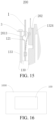
- the plurality of elastic pieces 2 respectively receive the forces that are toward the fixing plate 1, so that the elastic pieces 2 changes from a state shown by dashed lines in FIG. 15 to a state shown by solid lines.
- the elastic deformation of the elastic piece 2 produces appropriate axial pressure, so that the plurality of power switch tubes 202 can closely fit with the heat-dissipation wall of the shielding component 130.
- a threaded fastener such as a screw may be passed through the fixing lug 3 to fix the fixing apparatus 152 to the shielding component 130, as shown in FIG. 15 .
- a thermal insulation layer 151 is sandwiched between the power switch tube 202 and the liquid passage member 132. Therefore, the thermal insulation layer 151 can transfer the heat of the power switch tube 202 during operation to the liquid passage member 132, to reduce the temperature of the power switch tube 202 and improve the operating efficiency of the power switch tube 202. In addition, the thermal insulation layer 151 can further avoid the impact on the vehicle-mounted power supply apparatus 100 caused by current leakage of the power switch tube 202, thereby improving the usage safety and reliability of the vehicle-mounted power supply apparatus 100.
- the coolant channel 131 is annular, and the coolant channel 131 surrounds the periphery of the magnetic device 120.
- the annular coolant channel 131 can allow the coolant to circulate in the channel, so that the coolant can better absorb the heat of the vehicle-mounted power supply apparatus 100, reduce the temperature of the vehicle-mounted power supply apparatus 100, and improve the operating efficiency of the vehicle-mounted power supply apparatus 100.
- the coolant channel 131 at the periphery of the electromagnetic device 120, the heat emitted by the magnetic device 120 during operation can be absorbed by the coolant more quickly. This can improve the cooling effect of the coolant, to reduce the temperature of the vehicle-mounted power supply apparatus 100 during operation, thereby improving the operating efficiency of the vehicle-mounted power supply apparatus 100.
- a mounting groove 112 is provided at the mounting position 111, the magnetic device 120 is arranged in the mounting groove 112, the magnetic device 120 is connected to an inner wall of the mounting groove 112 through a screw, and a thermally conductive adhesive is arranged between the magnetic device 120 and the inner wall of the mounting groove 112. Therefore, the arrangement of the mounting groove 112 for assembling the magnetic device 120 further improves the assembly efficiency of the magnetic device 120.
- the connection of the magnetic device 120 through a screw makes the assembly of the magnetic device 120 more convenient, and facilitates the disassembly and maintenance of electrical components, thereby improving the assembly efficiency of the vehicle-mounted power supply apparatus 100.
- the thermal conductive adhesive arranged between the magnetic device 120 and the mounting groove 112 the heat generated by the magnetic device 120 during operation can be transferred to the inner wall of the mounting groove 112 more quickly, so that the heat of the magnetic device 120 can be dissipated more quickly, thereby improving the operating efficiency of the vehicle-mounted power supply apparatus 100.
- the magnetic device 120 according to the embodiments of the present disclosure will be described below with reference to FIG. 6 to FIG. 10 .
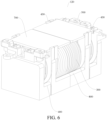
- the magnetic device 120 includes a magnetic core, a coil 300, a skeleton 400, a wire nose 500, and a nut 600.
- the coil 300 is wound on the magnetic core and has a pin 310.
- the skeleton 400 is arranged on the magnetic core.
- the wire nose 500 is mounted on the skeleton 400 and connected with the pin 310.
- the wire nose 500 has a connecting hole 510.
- the nut 600 is mounted on the skeleton 400, and the nut 600 has a threaded hole 610 corresponding to a position of the connecting hole 510.
- the circuit board connected with the magnetic device 120 may be arranged on one side of the wire nose 500 facing away from the skeleton 400.
- the circuit board may be provided with a threaded fastener (for example, a bolt or screw).
- the threaded fastener may be passed through the connecting hole 510 and threadedly connected to the threaded hole 610. As such, an electrical and mechanical connection can be realized between the circuit board and the magnetic device 120.
- the coil 300 is wound on the magnetic core and has the pin 310, the skeleton 400 is arranged on the magnetic core, and the wire nose 500 is mounted on the skeleton 400 and connected with the pin 310.
- an electrical connection can be realized between the wire nose 500 and the coil 300, and an electrical connection is realized between the circuit board and the coil 300 through the electrical connection of the circuit board with the wire nose 500.
- the wire nose 500 has the connecting hole 510
- the nut 600 is mounted on the skeleton 400
- the nut 600 has the threaded hole 610 corresponding to the position of the connecting hole 510
- the circuit board is connected to the threaded hole 610 of the nut 600 through the threaded fastener.
- the connection process is safe and reliable, the connection quality is easy to detect, the probability of damage of the magnetic device 120 is low, and the connection between the circuit board and the magnetic device 120 is stable. As welding is not required, the assembly and disassembly are convenient, providing good component replaceability and maintainability.
- the magnetic device 120 has the advantages of good component replaceability and maintainability, reliable connection, easy detection of connection quality, and the like.
- the wire nose 500 is movably mounted on the skeleton 400 to make the distance between the connecting hole 510 and the skeleton 400 adjustable. Since the circuit board is located on the side of the wire nose 500 facing away from the skeleton 400, the distance between the connecting hole 510 and the skeleton 400 can be adjusted by moving the wire nose 500, thereby improving the connection flatness between the magnetic device 120 and the circuit board.
- the wire nose 500 includes a plate portion 520, a bending portion 530, and a clamping portion 540.
- the connecting hole 510 is formed on the plate portion 520.
- the nut 600 is arranged between the plate portion 520 and the skeleton 400.
- One end of the bending portion 530 is connected to the plate portion 520.
- the bending portion 530 protrudes toward the skeleton 400.
- the bending portion 530 is movably mounted on the skeleton 400.
- the clamping portion 540 is connected to the other end of the bending portion 530 and clamps the pin 310.
- the clamping portion 540 can clamp the pin 310 from two opposite sides of the pin 310 in a radial direction to increase the connection stability between the wire nose 500 and the pin 310.
- the clamping portion 540 and the pin 310 may be welded or crimped.
- the bending portion 530 is configured as a U shape protruding toward the skeleton 400 to form a groove 531, and the clamping portion 540 is located in the groove 531.
- An opening direction of the clamping portion 540 is opposite to an opening direction of the groove 531.
- the opening direction of the groove 531 faces away from the magnetic core, and the opening direction of the clamping portion 540 faces toward the magnetic core.
- the connection part between the pin 310 and the clamping portion 540 is located inside the groove 531, thereby reducing the probability of external contact with the pin 310.
- the connection part between the pin 310 and the clamping portion 540 can be protected by arranging the groove 531, so as to increase the stability of the overall connection of the magnetic device 120.
- the skeleton 400 is provided with an assembly slot 410, and the bending portion 530 is movably engaged with the assembly slot 410.
- the bending portion 530 may be in an interference fit with the assembly slot 410.
- the wire nose 500 may be fixed to the skeleton 400 through a friction force between the bending portion 530 and the assembly slot 410. When an external force on the wire nose 500 is greater than the friction force between the bending portion 530 and the assembly slot 410, the wire nose 500 can move relative to the skeleton 400.
- the assembly slot 410 With the arrangement of the assembly slot 410, on the one hand, it can be used to accommodate the bending portion 530, to reduce the overall volume of the magnetic device 120, and facilitate product miniaturization. On the other hand, the relative positions of the skeleton 400 and the wire nose 500 can be fixed through the engagement of the bending portion 530 with the assembly slot 410, thereby improving the overall structural strength of the magnetic device 120.
- the skeleton 400 is provided with an anti-rotation groove 420
- the nut 600 is arranged in the anti-rotation groove 420, and a distance between the plate portion 520 and a bottom wall of the anti-rotation groove 420 is greater than an axial length of the nut 600.
- the nut 600 is non-circular, and a shape of the anti-rotation groove 420 matches a shape of the nut 600, for example, both the two are hexagonal.
- the nut 600 is fixed with respect to the relative position of the anti-rotation groove 420 along a circumferential direction.
- the threaded fastener such as a bolt or screw
- the nut 600 is prevented from rotating due to a circumferential force received by the nut 600, which increases the convenience of assembly.
- the distance between the plate portion 520 and the bottom wall of the anti-rotation groove 420 is greater than the axial length of the nut 600, the axial position of the nut 600 can be adjusted.
- a shortest distance between the plate portion 520 and the surface of the skeleton 400 facing toward the plate portion 520 may be less than the axial length of the nut 600, to prevent the nut 600 from falling off from the anti-rotation groove 420.
- the wire nose 500 further includes a positioning protrusion 550, the positioning protrusion 550 and the bending portion 530 are respectively connected to two opposite side edges of the plate portion 520.
- the skeleton 400 is provided with a positioning groove 440, and the positioning protrusion 550 is engaged with the positioning groove 440.
- the positioning protrusion 550 extends along an edge of the plate portion 520 toward the skeleton 400. The engagement of the positioning protrusion 550 and the positioning groove 440 makes the connection between the wire nose 500 and the skeleton 400 more stable, so that the relative positions of the wire nose 500 and the skeleton 400 are further fixed.
- the magnetic device 120 further includes a magnetic circuit piece 801 and at least one magnetic sheet 700, the magnetic core and skeleton 400 are carried on the magnetic circuit piece 801, and the magnetic sheet 700 is mounted on the skeleton 400.
- the magnetic sheet 700 may contain a magnetic material.
- the magnetic sheet 700 may have high permeability to effectively shield magnetic leakage generated by the coil 300.
- the magnetic sheet 700 may have high resistivity to reduce an eddy current loss caused by the addition of the magnetic sheet 700, thereby reducing the amount of heat generated by the magnetic device 120 and improving the overall efficiency of the magnetic device 120.
- the magnetic device 120 further includes a supporting portion 800.
- the supporting portion 800 is configured to support the coil 300.
- the supporting portion 800 is connected with the magnetic circuit piece 801, and the supporting portion 800 and the magnetic circuit piece 801 form an L-shaped structure.
- the magnetic core is arranged on one side of the magnetic circuit piece 801 facing toward the coil 300, and the magnetic core is arranged in the coil 300.
- the magnetic sheet 700 and the magnetic circuit piece 801 are respectively arranged on two opposite sides of the magnetic core. Since both the magnetic sheet 700 and the magnetic circuit piece 801 generate eddy current losses, the magnetic sheet 700 and the magnetic circuit piece 801 are respectively arranged on the two opposite sides of the transformer to prevent the concentration of heat generated by the magnetic sheet 700 and the magnetic circuit piece 801 and improve the heat dissipation efficiency for the magnetic sheet 700 and the magnetic circuit piece 801, thereby improving the overall efficiency of the magnetic device 120.
- the skeleton 400 is provided with a hook 430, and the hook 430 is hooked to an edge of the magnetic sheet 700.
- a plurality of hooks 430 may be arranged. The plurality of hooks 430 may be hooked at least to the two opposite side edges of the magnetic sheet 700 to increase the relative stability between the magnetic sheet 700 and the skeleton 400 and ensure the overall structural strength of the magnetic device 120.
- the shielding component 130 and the housing 110 are integrally formed. In this way, steps required for fabricating the shielding component 130 and the housing 110 can be saved, the process of fabricating the shielding component 130 and the housing 110 can be simplified, the connection strength between the shielding component 130 and the housing 110 can be improved, and the overall structural strength of the vehicle-mounted power supply apparatus 100 can be increased.
- a support 113 is arranged at a periphery of the housing 110, and the support 113 and the housing 110 are integrally formed.
- the integral forming can save the steps required for fabricating the support 113 and the housing 110, simplify the process of fabricating the support 113 and the housing 110, improve the connection strength between the support 113 and the housing 110, and increase the overall structural strength of the vehicle-mounted power supply apparatus 100.
- the support 113 can provide supporting stability for the housing 110, so that the loaded vehicle-mounted power supply apparatus 100 has higher usage safety and reliability.
- a vehicle 1000 includes the vehicle-mounted power supply apparatus 100 described above.
- the vehicle 1000 equipped with the vehicle-mounted power supply apparatus 100 has a good heat dissipation effect, which can reduce the operating temperature of the vehicle-mounted power supply apparatus 100 during the operation of the vehicle 1000, thereby improving the operating efficiency of the vehicle-mounted power supply apparatus 100.
Landscapes
- Engineering & Computer Science (AREA)
- Microelectronics & Electronic Packaging (AREA)
- Power Engineering (AREA)
- Physics & Mathematics (AREA)
- Thermal Sciences (AREA)
- Mechanical Engineering (AREA)
- Shielding Devices Or Components To Electric Or Magnetic Fields (AREA)
- Cooling Or The Like Of Electrical Apparatus (AREA)
- Coils Of Transformers For General Uses (AREA)
- Electric Propulsion And Braking For Vehicles (AREA)
- Regulation Of General Use Transformers (AREA)
- Dc-Dc Converters (AREA)
- Inverter Devices (AREA)
Abstract
Description
- The present disclosure claims priority to
Chinese Patent Application No. 202010658596.X, filed on July 09, 2020 - The present disclosure relates to the field of vehicle technologies, and specifically to a vehicle-mounted power supply apparatus and a vehicle having same.
- In related technologies, as a vehicle-mounted power supply adopts a planar design, the internal structure of the vehicle-mounted power supply is more complex and is prone to interference by external signals, reducing the operating efficiency of the vehicle-mounted power supply.
- The present disclosure aims to resolve at least one of the technical problems in the related art. Therefore, the present disclosure proposes a vehicle-mounted power supply apparatus. The vehicle-mounted power supply apparatus is characterized by simple structure, good heat dissipation and high operating efficiency.
- The present disclosure further provides a vehicle. The vehicle includes the vehicle-mounted power supply apparatus.
- A vehicle-mounted power supply apparatus according to an embodiment of the present disclosure includes: a housing, a magnetic device, and a shielding component. A mounting position is arranged in the housing. The magnetic device is an integrated part and is arranged at the mounting position. The shielding component is arranged in the housing, and the shielding component surrounds a periphery of the mounting position.
- In the vehicle-mounted power supply apparatus according to the embodiments of the present disclosure, the integrated design of the magnetic device can be easily realized by mounting the magnetic device at the mounting position, and then the shielding component is used to protect the magnetic device to shield the interference of external signals, thereby improving the stability and safety of the operation of the vehicle-mounted power supply apparatus.
- In some embodiments, a coolant channel is defined in the shielding component, and the coolant channel surrounds a periphery of the magnetic device.
- In some embodiments, the shielding component includes: a liquid passage member and a shielding wall. The coolant channel is defined in the liquid passage member. The shielding wall is separated from the liquid passage member, and the shielding wall is located on a side of the liquid passage member away from the magnetic device.
- In some embodiments, one side of the coolant channel is provided with an open opening; and the shielding component further includes: a liquid passage cover plate and a sealing ring. The liquid passage cover plate is hermetically connected with the liquid passage member to close the open opening. The sealing ring is sandwiched between the liquid passage cover plate and the liquid passage member.
- In some embodiments, the liquid passage member includes a first sidewall and a second sidewall separated from the first sidewall, the coolant channel is defined between the first sidewall and the second sidewall, the first sidewall faces toward the magnetic device, the second sidewall is located on a side of the first sidewall away from the magnetic device, and a distance between the first sidewall and the second sidewall gradually decreases in a direction toward the open opening.
- In some embodiments, the vehicle-mounted power supply apparatus further includes: a circuit board, a plurality of power switch tubes, and a fixing apparatus. Each of the power switch tubes is respectively electrically connected with the circuit board. The fixing apparatus is configured for simultaneously fixing the plurality of power switch tubes between the liquid passage member and the shielding wall.
- In some embodiments, the fixing apparatus includes: a fixing plate and a plurality of elastic pieces. Each of the elastic pieces is configured for fixing one power switch tube. One end of each of the elastic pieces is fixed to the fixing plate, and the other end of each of the elastic pieces is located at one side of the fixing plate in a thickness direction and is separated from a surface on the one side of the fixing plate in the thickness direction.
- In some embodiments, each of the elastic pieces includes: a fixing segment, a connection segment, and a pressing segment. The fixing segment is fixed on the fixing plate. The connection segment is connected between the fixing segment and the pressing segment. The pressing segment includes a first pressing portion and a second pressing portion. One end of the first pressing portion is connected with the connection segment, and an other end of the first pressing portion extends away from the fixing plate. One end of the second pressing portion is connected with the other end of the first pressing portion, and an other end of the second pressing portion extends toward the fixing plate.
- In some embodiments, at least one boss is arranged on an other side of the fixing plate in the thickness direction, and a cross-sectional area of the boss gradually decreases in a direction away from the fixing plate; and the boss is formed by a part of the surface on the one side of the fixing plate in the thickness direction protruding toward a surface on the other side of the fixing plate in the thickness direction.
- In some embodiments, an edge of the fixing plate is provided with at least one pull lug extending away from a center of the fixing plate; the fixing apparatus further includes: at least one pull lug piece, where the pull lug piece is arranged on one side of the pull lug in a thickness direction; and an edge of the fixing plate is provided with at least one fixing lug, and a free end of the fixing lug extends toward the other side of the fixing plate along the thickness direction of the fixing plate.
- In some embodiments, the magnetic device includes: a magnetic core, a coil, a skeleton, a wire nose, and a nut. The coil is wound on the magnetic core and has a pin. The skeleton is arranged on the magnetic core. The wire nose is mounted on the skeleton and connected with the pin, and the wire nose has a connecting hole. The nut is mounted on the skeleton, and the nut has a threaded hole corresponding to a position of the connecting hole.
- In some embodiments, the wire nose is movably mounted on the skeleton to make a distance between the connecting hole and the skeleton adjustable; and the wire nose includes: a plate portion, a bending portion, and a clamping portion. The connecting hole is formed in the plate portion, and the nut is arranged between the plate portion and the skeleton. One end of the bending portion is connected to the plate portion, the bending portion protrudes toward the skeleton, the bending portion is movably mounted on the skeleton, and the bending portion is configured as a U shape protruding toward the skeleton to form a groove. The clamping portion is connected to the other end of the bending portion and clamps the pin, and the clamping portion is located in the groove.
- In some embodiments, the skeleton is provided with an anti-rotation groove, the nut is arranged in the anti-rotation groove, and a distance between the plate portion and a bottom wall of the anti-rotation groove is greater than an axial length of the nut.
- In some embodiments, the wire nose further includes: a positioning protrusion, where the positioning protrusion and the bending portion are respectively connected to two opposite side edges of the plate portion, the skeleton is provided with a positioning groove, and the positioning protrusion is engaged with the positioning groove.
- In some embodiments, the vehicle-mounted power supply apparatus further includes: a magnetic circuit piece and at least one magnetic sheet. The magnetic core and the skeleton are carried on the magnetic circuit piece. The magnetic sheet is mounted on the skeleton, the magnetic sheet and the magnetic circuit piece are respectively arranged on two opposite sides of the magnetic core, the skeleton is provided with a hook, and the hook is hooked to an edge of the magnetic sheet.
- A vehicle according to an embodiment of the present disclosure includes the vehicle-mounted power supply apparatus described above.
- The additional aspects and advantages of the present disclosure will be provided in the following description, some of which will become apparent from the following description or may be learned from practices of the present disclosure.
- The foregoing and/or additional aspects and advantages of the present disclosure will become apparent and comprehensible from the following descriptions of the embodiments with reference to the accompanying drawings, where:
-
FIG. 1 is a schematic diagram of a vehicle-mounted power supply apparatus according to an embodiment of the present disclosure. -
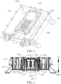
FIG. 2 is a three-dimensional diagram of a vehicle-mounted power supply apparatus according to an embodiment of the present disclosure. -
FIG. 3 is a cross-sectional view of a vehicle-mounted power supply apparatus according to an embodiment of the present disclosure. -
FIG. 4 is a partial cross-sectional view of a vehicle-mounted power supply apparatus according to an embodiment of the present disclosure. -
FIG. 5 is a partial cross-sectional view of a vehicle-mounted power supply apparatus according to an embodiment of the present disclosure. -
FIG. 6 is a schematic structural diagram of a magnetic device according to an embodiment of the present disclosure. -
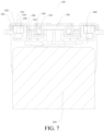
FIG. 7 is a cross-sectional view of a magnetic device according to an embodiment of the present disclosure. -
FIG. 8 is an exploded view of a magnetic device according to an embodiment of the present disclosure. -
FIG. 9 is a schematic assembled view of a wire nose and a skeleton of a magnetic device according to an embodiment of the present disclosure. -
FIG. 10 is a schematic structural diagram of a wire nose of a magnetic device according to an embodiment of the present disclosure. -
FIG. 11 is a three-dimensional diagram of a fixing apparatus for power switch tubes according to an embodiment of the present disclosure. -
FIG. 12 is an exploded view of the fixing apparatus shown inFIG. 11 . -
FIG. 13 is a three-dimensional diagram of a fixing apparatus for power switch tubes according to an embodiment of the present disclosure. -
FIG. 14 is a cross-sectional view of a switch tube assembly according to an embodiment of the present disclosure before power switch tubes are press-fit. -
FIG. 15 is cross-sectional view of the switch tube assembly shown inFIG. 14 after the power switch tubes are press-fit. -
FIG. 16 is a block diagram of a vehicle according to an embodiment of the present disclosure. -
- vehicle-mounted
power supply apparatus 100, -
housing 110, mountingposition 111, mountinggroove 112,support 113, -
magnetic device 120, - shielding
component 130,coolant channel 131,liquid passage member 132,first segment 1321,second segment 1322,first sidewall 1323,second sidewall 1324, shieldingwall 133, liquidpassage cover plate 134, sealingring 135, -
thermal insulation layer 151, fixingapparatus 152, -
coil 300,pin 310, -
skeleton 400,assembly slot 410,anti-rotation groove 420,hook 430,positioning groove 440, -
wire nose 500, connectinghole 510,plate portion 520, bendingportion 530,groove 531, clampingportion 540,positioning protrusion 550, -
nut 600, threadedhole 610, -
magnetic sheet 700, supportingportion 800,magnetic circuit piece 801, - fixing
plate 1,elastic piece 2, - fixing
segment 21,connection segment 22, pressingsegment 23, - first
pressing portion 231, secondpressing portion 232, - fixing
lug 3,boss 4, pulllug 5, pulllug piece 51, -
chamfer 121, - guide
surface 2013,power switch tube 202, -
vehicle 1000. - The embodiments of the present invention are described in detail below, and the embodiments described with reference to accompanying drawings are exemplary.
- A vehicle-mounted
power supply apparatus 100 according to an embodiment of the present disclosure will be described below with reference toFIG. 1 to FIG. 5 , which includes: ahousing 110, amagnetic device 120, and ashielding component 130. - Specifically, a mounting
position 111 is arranged in thehousing 110, and themagnetic device 120 is an integrated part and is arranged at the mountingposition 111. It should be noted herein that by arranging the mountingposition 111 inside thehousing 110, themagnetic device 120 may be centrally arranged at the mountingposition 111, thereby improving the integration degree of the vehicle-mountedpower supply apparatus 100. Theshielding component 130 is arranged in thehousing 110, and theshielding component 130 surrounds a periphery of the mountingposition 111. Theshielding component 130 can be used to shield electromagnetic signals, thereby protecting themagnetic device 120. - In the vehicle-mounted
power supply apparatus 100 according to the embodiments of the present disclosure, the integrated design of themagnetic device 120 can be easily realized by mounting themagnetic device 120 at the mountingposition 111, and then theshielding component 130 is used to protect themagnetic device 120 to shield the interference of external signals, thereby improving the stability and safety of the operation of the vehicle-mountedpower supply apparatus 100. - In the embodiment shown in
FIG. 3 andFIG. 4 , acoolant channel 131 is defined in theshielding component 130, and thecoolant channel 131 surrounds a periphery of themagnetic device 120. It should be noted that, thecoolant channel 131 may be provided therein with a coolant. When the coolant flows, heat exchange occurs between the coolant near themagnetic device 120 and themagnetic device 120, that is, the coolant can cool themagnetic device 120. The flow of the coolant can take away heat generated by themagnetic device 120, so as to cool and dissipate heat from themagnetic device 120. By arranging thecoolant channel 131 to surround the periphery of themagnetic device 120, thecoolant channel 131 can be close to more positions on themagnetic device 120, thereby improving the cooling efficiency of thecoolant channel 131. - As shown in
FIG. 3 andFIG. 4 , theshielding component 130 may include: aliquid passage member 132 and ashielding wall 133. Thecoolant channel 131 is defined in theliquid passage member 132. The shieldingwall 133 is separated from theliquid passage member 132, and the shieldingwall 133 is located on a side of theliquid passage member 132 away from themagnetic device 120. It can be understood that, theliquid passage member 132 is closer to themagnetic device 120 than the shieldingwall 133 is, that is, theliquid passage member 132 is arranged adjacent to themagnetic device 120, thereby facilitating the cooling of themagnetic device 120 by thecoolant channel 131. By arranging the shieldingwall 133 around theliquid passage member 132, themagnetic device 120 and theliquid passage member 132 can be protected at the same time. - As shown in
FIG. 2 , according to some embodiments of the present disclosure, theliquid passage member 132 may include afirst segment 1321 and asecond segment 1322 separated from thefirst segment 1321, and themagnetic device 120 is sandwiched between thefirst segment 1321 and thesecond segment 1322. It can be understood that thefirst segment 1321 is located on one side of themagnetic device 120, and thesecond segment 1322 is located on the other side of themagnetic device 120, so as to dissipate heat from themagnetic device 120 from multiple directions. In addition, theliquid passage member 132 arranged on two sides of themagnetic device 120 can limit themagnetic device 120, thereby improving the assembly stability of themagnetic device 120. - As shown in
FIG. 3 andFIG. 4 , in some embodiments, one side of thecoolant channel 131 is provided with an open opening, and theshielding component 130 further includes: a liquidpassage cover plate 134. The liquidpassage cover plate 134 is hermetically connected with theliquid passage member 132 to close the open opening. Therefore, on the one hand, it is convenient to fill the coolant into thecoolant channel 131. On the other hand, the liquidpassage cover plate 134 can be used to seal the open opening, thereby simplifying the structure of theliquid passage member 132 and facilitating the replacement and maintenance of theliquid passage member 132. - In some embodiments, the liquid
passage cover plate 134 is welded to theliquid passage member 132, or the liquidpassage cover plate 134 is connected to theliquid passage member 132 by a screw. In this way, the liquidpassage cover plate 134 and theliquid passage member 132 can be fixed by welding or by bolt connection. When the liquidpassage cover plate 134 and theliquid passage member 132 are connected by welding, a coolant with high heat exchange effect may be used to extend the heat dissipation effect of theliquid passage member 132, and at the same time, theliquid passage member 132 can also have higher stability and avoid coolant leakage. - When the liquid
passage cover plate 134 and theliquid passage member 132 are connected and fixed by a screw, the coolant that exchanges heat in thecoolant channel 131 has a higher use effect, thereby increasing the heat dissipation effect of theliquid passage member 132. In addition, the liquidpassage cover plate 134 and theliquid passage member 132 connected by a bolt have good detachable performance, which not only improves the assembly efficiency of theliquid passage member 132, but also facilitates the disassembly of theliquid passage member 132. This improves the assembly and disassembly efficiency of theliquid passage member 132, and facilitates the use, maintenance and repair of the vehicle-mountedpower supply apparatus 100. - Referring to
FIG. 3 andFIG. 4 , in some embodiments, theshielding component 130 further includes: a sealingring 135. The sealingring 135 is sandwiched between the liquidpassage cover plate 134 and theliquid passage member 132. Therefore, the sealingring 135 arranged between the liquidpassage cover plate 134 and theliquid passage member 132 provides a better sealing performance for thecoolant channel 131 on theliquid passage member 132, which can further avoid liquid leakage and other situations, and further increase the usage reliability of thecoolant channel 131. In addition, the sealingring 135 sandwiched between the liquidpassage cover plate 134 and theliquid passage member 132 can facilitate the assembly of the liquidpassage cover plate 134 and improve the assembly efficiency of the liquidpassage cover plate 134. In addition, when the liquidpassage cover plate 134 is to be disassembled, the sealingring 135 can reduce the adhesion resistance between the liquidpassage cover plate 134 and theliquid passage member 132, so that the disassembly convenience of the liquidpassage cover plate 134 can be improved, thereby further facilitating the use, maintenance and repair of the vehicle-mountedpower supply apparatus 100. - In the embodiment shown in
FIG. 3 andFIG. 4 , theliquid passage member 132 may include afirst sidewall 1323 and asecond sidewall 1324 separated from thefirst sidewall 1323. Thecoolant channel 131 is defined between thefirst sidewall 1323 and thesecond sidewall 1324. Thefirst sidewall 1323 faces toward themagnetic device 120. Thesecond sidewall 1324 is located on a side of thefirst sidewall 1323 away from themagnetic device 120. A distance between thefirst sidewall 1323 and thesecond sidewall 1324 gradually decreases in a direction toward the open opening. In this way, thecoolant channel 131 is defined to be narrow in the upper part and wide in the lower part, so as to facilitate the demolding of theliquid passage member 132 and improve the yield of theliquid passage member 132. In addition, thefirst sidewall 1323 facing toward themagnetic device 120 can better exchange heat with themagnetic device 120 to improve the cooling efficiency of theliquid passage member 132, thereby improving the operating efficiency of the vehicle-mountedpower supply apparatus 100. - As shown in
FIG. 5 , in some embodiments, the vehicle-mountedpower supply apparatus 100 further includes: a circuit board (not shown),power switch tubes 202, and a fixing apparatus. Thepower switch tubes 202 are electrically connected with the circuit board. Thepower switch tubes 202 are arranged between theliquid passage member 132 and the shieldingwall 133. The fixingapparatus 152 is configured for simultaneously fixing a plurality ofpower switch tubes 202 between theliquid passage member 132 and the shieldingwall 133. - The
power switch tubes 202 can control on/off of a circuit on the circuit board. Therefore, the arrangement of thepower switch tubes 202 on the shieldingwall 133 can not only enable the shieldingwall 133 to better support thepower switch tubes 202 and enable thepower switch tubes 202 to better control on/off of the circuit on the circuit board, but also enable the shieldingwall 133 to shield the interference of external signals on thepower switch tubes 202, allowing thepower switch tubes 202 to more precisely control the circuit board. - In addition, the fixing
apparatus 152 is further arranged on an outer side of thepower switch tube 202. The fixingapparatus 152 has a function of press-fitting thepower switch tube 202. The fixingapparatus 152 deforms during the press-fit process, and thedeformed fixing apparatus 152 has axial pressure, which sticks thepower switch tube 202 and theliquid passage member 132 together, thereby providing thepower switch tube 202 with high stability. In addition, after the fixingapparatus 152 is arranged to fix thepower switch tube 202, the fixingapparatus 152 also has good heat exchange capacity, so that the heat generated by thepower switch tube 202 during operation can be transferred through the fixingapparatus 152, to lower the operating temperature of thepower switch tube 202 and improve the operating efficiency of thepower switch tube 202. In addition, the fixingapparatus 152 can fix a plurality ofpower switch tubes 202 at a time, achieving high fixing efficiency. In addition, the fixing process of the fixingapparatus 152 can also be simplified to improve the assembly efficiency of the vehicle-mountedpower supply apparatus 100. - The fixing
apparatus 152 forpower switch tubes 202 according to the embodiments of the present disclosure will be described below with reference toFIG. 11 to FIG. 15 . - It should be noted that, the fixing
apparatus 152 fixes thepower switch tube 202 to theliquid passage member 132 of theshielding component 130. Specifically, thepower switch tube 202 is bonded with thesecond sidewall 1324, so that the fixingapparatus 152 squeezes thepower switch tube 202 to thesecond sidewall 1324. Thesecond sidewall 1324 provides support for thepower switch tube 202. In addition, thepower switch tube 202 can transfer the heat generated during operation to thesecond sidewall 1324 to reduce the operating temperature of thepower switch tube 202 and improve the operating efficiency of thepower switch tube 202. Thefirst sidewall 1323 of theliquid passage member 132 is located at the side away from thepower switch tube 202, and can absorb the heat emitted by themagnetic device 120 during operation. Theshielding component 130 further includes the shieldingwall 133. The shieldingwall 133 is located on the other side away from thepower switch tube 202 and can shield external interference signals, including interference signals to thepower switch tube 202 and interference signals to themagnetic device 120 inside thepower switch tube 202. This embodiment only introduces the bonding and interaction of thepower switch tube 202 with thesecond sidewall 1324 under the action of the fixingapparatus 152. Thefirst sidewall 1323 and the shieldingwall 133 have been introduced in the context, and will not be repeated here. - As shown in
FIG. 11 to FIG. 13 , the fixingapparatus 152 forpower switch tubes 202 according to an embodiment of the present disclosure includes a fixingplate 1 and a plurality ofelastic pieces 2. - Specifically, each
elastic piece 2 is used to fix onepower switch tube 202, and one end of each elastic piece 2 (for example, a lower end inFIG. 11 ) is fixed to the fixingplate 1. In this case, the one end of eachelastic piece 2 is fixed relative to the fixingplate 1. The other end of each elastic piece 2 (for example, an upper end inFIG. 11 ) is located on one side of the fixingplate 1 in the thickness direction, and the other end of eachelastic piece 2 is separated from a surface on the one side of the fixingplate 1 in the thickness direction. - When the fixing
apparatus 152 forpower switch tubes 202 is applied to aswitch tube assembly 200, with reference toFIG. 14 andFIG. 15 , in order to make the plurality ofpower switch tubes 202 closely fit on an inner wall of theshielding component 130, such as thesecond sidewall 1324, where the plurality ofpower switch tubes 202 are mounted, operation personnel only needs to insert the fixingplate 1 having the plurality of elastic pieces into theshielding component 130. In the above process, the other end of the plurality ofelastic pieces 2 can move toward the fixingplate 1 under the action of the correspondingpower switch tube 202, and due to an elastic force of theelastic piece 2 itself, the other end of the plurality ofelastic pieces 2 can respectively apply a force toward thesecond sidewall 1324 to the correspondingpower switch tube 202, thereby tightly pressing the plurality ofpower switch tubes 202 onto thesecond sidewall 1324. This enables the plurality ofpower switch tubes 202 to closely fit with thesecond sidewall 1324, thereby realizing effective heat dissipation for the plurality ofpower switch tubes 202 and prolonging the service life of the plurality ofpower switch tubes 202. Therefore, compared with the related art in which eachpower switch tube 202 requires the use of a corresponding screw to lock theelastic piece 2 to achieve press-fit and fixation, the fixingapparatus 152 including the fixingplate 1 and the plurality ofelastic pieces 2 is an integral structure, which can press-fit a plurality ofpower switch tubes 202 at a time, thereby simplifying the assembly process, improving the assembly efficiency, and facilitating subsequent disassembly. The disassembly can be done at a time. - The fixing
apparatus 152 forpower switch tubes 202 according to the embodiments of the present disclosure include the fixingplate 1 and the plurality ofelastic pieces 2, where one end of eachelastic piece 2 is fixed to the fixingplate 1, the other end of eachelastic piece 2 is located on one side of the fixingplate 1 in the thickness direction and is separated from the surface on the one side of the fixingplate 1 in the thickness direction. The fixingapparatus 152 has a simple structure. When the fixingapparatus 152 is applied to theswitch tube assembly 200, the assembly efficiency of the fixingapparatus 152 is high. - As shown in
FIG. 11 , eachelastic piece 2 includes a fixingsegment 21, a pressingsegment 23, and aconnection segment 22. The fixingsegment 21 is fixed on the fixingplate 1, and eachelastic piece 2 is fixedly connected to the fixingplate 1 through the fixingsegment 21. The pressingsegment 23 is located on the one side of the fixingplate 1 in the thickness direction, and thepressing segment 23 is separated from the surface on the one side of the fixingplate 1 in the thickness direction. When the fixingapparatus 152 is applied to theswitch tube assembly 200, eachelastic piece 2 can tightly press the correspondingpower switch tube 202 through the pressingsegment 23 to fit with the inner wall of theshielding component 130, such as thesecond sidewall 1324. Theconnection segment 22 is connected between the fixingsegment 21 and thepressing segment 23. In this way, it can be effectively ensured that eachelastic piece 2 has sufficient elasticity, so that thepower switch tube 202 can be reliably and tightly pressed in theshielding component 130. - Referring to
FIG. 11 , the pressingsegment 23 includes a firstpressing portion 231 and a secondpressing portion 232. One end of the first pressing portion 231 (for example, a lower end inFIG. 11 ) is connected with theconnection segment 22, and the other end of the first pressing portion 231 (for example, an upper end inFIG. 11 ) extends away from the fixingplate 1. One end of the second pressing portion 232 (for example, a lower end inFIG. 11 ) is connected with the other end of the firstpressing portion 231, and the other end of the second pressing portion 232 (for example, an upper end inFIG. 11 ) extends toward the fixingplate 1. In this case, the connection between the firstpressing portion 231 and the secondpressing portion 232 is suitable for stopping with thepower switch tube 202. Therefore, by arranging thepressing segment 23 to include the firstpressing portion 231 and the secondpressing portion 232, the fixingapparatus 152 can be more smoothly mounted into theshielding component 130, and the end of thepressing segment 23 is not easy to contact thepower switch tube 202 directly, thereby extending the service life of thepower switch tube 202. Optionally, there may be a smooth transition between the firstpressing portion 231 and the secondpressing portion 232. In this way, the contact area between thepressing segment 23 and thepower switch tube 202 can be increased, and the force exerted by the pressingsegment 23 on thepower switch tube 202 can be more uniform, thereby effectively ensuring that thepower switch tube 202 as a whole closely fits thesecond sidewall 1324, providing a good heat dissipation effect. - Optionally, a length of the second
pressing portion 232 may be less than that of the firstpressing portion 231, to save materials while ensuring that the pressing portion has a sufficient force on thepower switch tube 202, thereby reducing the costs. - Referring to
FIG. 11 to FIG. 13 as well asFIG. 14 to 15 , an angle between the firstpressing portion 231 and the fixingplate 1 is greater than an angle between theconnection segment 22 and the fixingplate 1. In this case, compared with theconnection segment 22, an inclination angle of the firstpressing portion 231 is greater, and there may be a smooth transition at the connection between the firstpressing portion 231 and theconnection segment 22. Through such arrangement, eachelastic piece 2 can be gradually extended away from the fixingplate 1, and the service life of theelastic piece 2 can be extended while ensuring a sufficient elastic force. - As shown in
FIG. 11 to FIG. 12 , the plurality ofelastic pieces 2 constitute at least one elastic piece group. The elastic piece group includes at least twoelastic pieces 2 arranged side by side. One end of each of the at least twoelastic pieces 2 is fixed to the fixingplate 1, and the other ends of the at least twoelastic pieces 2 are separated from each other. Such arrangement is convenient for processing and can reduce the costs. For example, in an example ofFIG. 11 and FIG. 12 , seven elastic piece groups are shown. The seven elastic piece groups are arranged at intervals along a length direction of the fixingplate 1. Each elastic piece group includes twoelastic pieces 2 arranged along the length direction of the fixingplate 1. Lower ends of the twoelastic pieces 2 are connected, and upper ends of the twoelastic pieces 2 are separated from each other for respectively stopping with the correspondingpower switch tubes 202. The at least twoelastic pieces 2 in each elastic piece group may be integrally formed. - The seven elastic piece groups shown in
FIG. 11 and FIG. 12 may include three first elastic piece groups and four second elastic piece groups. The length and width of theelastic piece 2 in each first elastic piece group may be different from the length and width of theelastic piece 2 in each second elastic piece group, so as to adapt topower switch tubes 202 of different sizes. - Optionally, each
elastic piece 2 may be riveted (as shown inFIG. 11 and FIG. 12 ), welded (not shown) or threadedly connected (not shown) to the fixingplate 1. Therefore, the production process is simple. Of course, the present disclosure is not limited thereto, and the plurality ofelastic pieces 2 may also be integrally formed with the fixingplate 1, as shown inFIG. 13 . For example, the plurality ofelastic pieces 2 may be formed from the fixingplate 1 by stamping. - According to some embodiments of the present disclosure, as shown in
FIG. 12 to FIG. 15 , at least oneboss 4 is arranged on the other side of the fixingplate 1 in the thickness direction. Theboss 4 protrudes from the surface on the other side of the fixingplate 1 in the thickness direction. In this way, when the fixingapparatus 152 is assembled into theshielding component 130, theboss 4 stops against the shieldingwall 133 opposite to thesecond sidewall 1324 in theshielding component 130. In this case, theboss 4 can be engaged with theelastic piece 2, so that theelastic piece 2 can exert a greater force on thepower switch tube 202, so that thepower switch tube 202 can be more closely fit to thesecond sidewall 1324 of theshielding component 130. - As shown in
FIG. 14 andFIG. 15 , a cross-sectional area of theboss 4 gradually decreases in a direction away from the fixingplate 1. Specifically, at least one side surface of theboss 4 may be formed as achamfer 121, for example, at least a lower side surface of theboss 4 may be formed as achamfer 121, so that the fixingapparatus 152 can be more smoothly assembled into theshielding component 130. - Optionally, referring to
FIG. 11 to FIG. 12 as well asFIG. 13 to FIG. 14 , theboss 4 may be formed by a part of the surface on the one side of the fixingplate 1 in the thickness direction protruding toward a surface on the other side of the fixingplate 1 in the thickness direction. For example, theboss 4 may be formed by stamping to simplify the fabrication process of theboss 4 and reduce the costs. Of course, theboss 4 may also be a solid structure arranged on the surface of the other side of the fixingplate 1 in the thickness direction. - According to some embodiments of the present disclosure, referring to
FIG. 11 to FIG. 12 , a plurality ofbosses 4 may be arranged, and the plurality ofbosses 4 are arranged at intervals along the arrangement direction of the plurality ofelastic pieces 2. Therefore, the arrangement of the plurality ofbosses 4 can effectively ensure that the plurality of elastic pieces respectively exert a large force on the correspondingpower switch tubes 202. It can be understood that the number ofbosses 4 may be less than the number ofelastic pieces 2, as long as it can ensure that the plurality ofelastic pieces 2 can tightly press the correspondingpower switch tubes 202 in theshielding component 130. - According to some embodiments of the present disclosure, as shown in
FIG. 12 , an edge of the fixingplate 1 is provided with at least onepull lug 5 extending away from a center of the fixingplate 1. For example, in an example ofFIG. 12 , two pulllugs 5 are shown, and the twopull lugs 5 may be in the same plane with the fixingplate 1. When it is necessary to insert the fixingapparatus 152 into theshielding component 130, operation personnel may hold the twopull lugs 5 and insert the fixingapparatus 152 into theshielding component 130 from top to bottom, so that the plurality ofelastic pieces 2 can closely fit with thesecond sidewall 1324 of theshielding component 130. When it is necessary to take out the fixingapparatus 152, the twopull lugs 5 may be pulled upward, so that the fixingapparatus 152 can be conveniently pulled out. Therefore, the assembly and disassembly of the fixingapparatus 152 can be more conveniently realized by arranging thepull lug 5. - The two
pull lugs 5 shown inFIG. 11 to FIG. 12 are for the purpose of illustration. After reading the technical solution of the present disclosure, those of ordinary skill in the art can obviously understand that the application of this solution to technical solutions involving three or more pull lugs 5 also falls within the scope of protection of the present disclosure. - According to some embodiments of the present disclosure, as shown in
FIG. 11 and FIG. 12 , the fixingapparatus 152 may include at least onepull lug piece 51. Thepull lug piece 51 is arranged on one side of thepull lug 5 in a thickness direction. For example, as shown inFIG. 12 , thepull lug piece 51 may include a first segment and a second segment connected with each other, a length of the first segment of thepull lug piece 51 may be equal to a length of thepull lug 5, a width of the first segment of thepull lug piece 51 may be equal to a width of thepull lug 5, and a width of the second segment may be greater than the width of the first segment. During assembly, the first segment of thepull lug piece 51 may correspond to thepull lug 5, and the second segment of thepull lug piece 51 may be fixed to the fixingplate 1 by riveting or welding. Therefore, thepull lug 5 can be reinforced by arranging thepull lug piece 51, thereby improving the structural strength of thepull lug 5. The number ofpull lug pieces 51 may be equal to or less than the number of pull lugs 5. It can be understood that the actual number ofpull lug pieces 51 may be set according to actual requirements to better meet the practical application. - According to some embodiments of the present disclosure, with reference to
FIG. 11 andFIG. 14 , the edge of the fixingplate 1 is provided with at least one fixinglug 3. Therefore, by arranging the fixinglug 3, the fixingapparatus 152 can be fixedly connected to theshielding component 130 through the fixinglug 3. A free end of the fixinglug 3 extends toward the other side of the fixingplate 1 along the thickness direction of the fixingplate 1. In this way, after the fixingapparatus 152 is assembled on theshielding component 130, the fixinglug 3 is located on the top of theshielding component 130, and the fixinglug 3 is exposed out of theshielding component 130. In this case, a threaded fastener may be passed through the fixinglug 3 and threadedly connected to theshielding component 130, so the assembly is convenient. Compared with the related art in which an opening is provided at the bottom of theshielding component 130 or a large number of through holes are provided on the top circuit board, the fixingapparatus 152 requires less mounting space, and there is no need to reserve operation space required for fixing the fixingapparatus 152. In addition, the fixinglug 3 also has a positioning function. Specifically, when the fixinglug 3 is assembled to contact the top of theshielding component 130, it indicates that the fixingapparatus 152 has been mounted in place. In this case, theelastic piece 2 makes thepower switch tube 202 closely fit with thesecond sidewall 1324 of theshielding component 130. - As shown in
FIG. 14 andFIG. 15 , theswitch tube assembly 200 according to an embodiment of the present disclosure includes ashielding component 130, a plurality ofpower switch tubes 202, and a fixingapparatus 152. The fixingapparatus 152 is the fixingapparatus 152 forpower switch tubes 202 according to the above embodiments of the present disclosure. - Specifically, the plurality of
power switch tubes 202 are all arranged in theshielding component 130. The fixingapparatus 152 is arranged in theshielding component 130, and the other ends of the plurality ofelastic pieces 2 of the fixingapparatus 152 tightly press the plurality ofpower switch tubes 202 in theshielding component 130. - For the
switch tube assembly 200 according to the embodiment of the present disclosure, by using theabove fixing apparatus 152, the fixingapparatus 152 can be conveniently assembled into theshielding component 130, so the assembly is convenient. Moreover, the plurality ofpower switch tubes 202 can be stopped against thesecond sidewall 1324 in theshielding component 130 under the action of the plurality ofelastic pieces 2, which can better realize heat dissipation and extend the service life of thepower switch tubes 202. - According to some embodiments of the present disclosure, referring to
FIG. 14 andFIG. 15 , at least oneboss 4 is arranged on the other side of the fixingplate 1 in the thickness direction. Aguide surface 2013 is arranged on a surface of one side of theshielding component 130 facing toward theboss 4. Theguide surface 2013 extends obliquely toward theboss 4 along the insertion direction of the fixingapparatus 152. Therefore, by arranging theguide surface 2013, theguide surface 2013 has a guiding effect for theboss 4, so that the fixingapparatus 152 can be more smoothly assembled to theshielding component 130. - As shown in
FIG. 14 , before the plurality ofpower switch tubes 202 are tightly pressed, theboss 4 on the fixingplate 1 is vertically staggered from theguide surface 2013 on the shieldingwall 133 of theshielding component 130. In this case, the plurality ofelastic pieces 2 have not pressed to the correspondingpower switch tubes 202. - During the downward insertion of the fixing
apparatus 152, theboss 4 contacts theguide surface 2013 on the shieldingwall 133 of theshielding component 130. Afterward, as the downward pressing continues, the fixingapparatus 152 as a whole moves toward thepower switch tubes 202 under the stop action of the boss and the sidewall of the box. In this case, the plurality ofelastic pieces 2 respectively receive the forces that are toward the fixingplate 1, so that theelastic pieces 2 changes from a state shown by dashed lines inFIG. 15 to a state shown by solid lines. In this case, the elastic deformation of theelastic piece 2 produces appropriate axial pressure, so that the plurality ofpower switch tubes 202 can closely fit with the heat-dissipation wall of theshielding component 130. - Finally, a threaded fastener such as a screw may be passed through the fixing
lug 3 to fix thefixing apparatus 152 to theshielding component 130, as shown inFIG. 15 . - In the embodiment shown in
FIG. 6 , athermal insulation layer 151 is sandwiched between thepower switch tube 202 and theliquid passage member 132. Therefore, thethermal insulation layer 151 can transfer the heat of thepower switch tube 202 during operation to theliquid passage member 132, to reduce the temperature of thepower switch tube 202 and improve the operating efficiency of thepower switch tube 202. In addition, thethermal insulation layer 151 can further avoid the impact on the vehicle-mountedpower supply apparatus 100 caused by current leakage of thepower switch tube 202, thereby improving the usage safety and reliability of the vehicle-mountedpower supply apparatus 100. - In some embodiments, the
coolant channel 131 is annular, and thecoolant channel 131 surrounds the periphery of themagnetic device 120. In this way, theannular coolant channel 131 can allow the coolant to circulate in the channel, so that the coolant can better absorb the heat of the vehicle-mountedpower supply apparatus 100, reduce the temperature of the vehicle-mountedpower supply apparatus 100, and improve the operating efficiency of the vehicle-mountedpower supply apparatus 100. In addition, by arranging thecoolant channel 131 at the periphery of theelectromagnetic device 120, the heat emitted by themagnetic device 120 during operation can be absorbed by the coolant more quickly. This can improve the cooling effect of the coolant, to reduce the temperature of the vehicle-mountedpower supply apparatus 100 during operation, thereby improving the operating efficiency of the vehicle-mountedpower supply apparatus 100. - In some embodiments, as shown in
FIG. 3 , a mountinggroove 112 is provided at the mountingposition 111, themagnetic device 120 is arranged in the mountinggroove 112, themagnetic device 120 is connected to an inner wall of the mountinggroove 112 through a screw, and a thermally conductive adhesive is arranged between themagnetic device 120 and the inner wall of the mountinggroove 112. Therefore, the arrangement of the mountinggroove 112 for assembling themagnetic device 120 further improves the assembly efficiency of themagnetic device 120. In addition, the connection of themagnetic device 120 through a screw makes the assembly of themagnetic device 120 more convenient, and facilitates the disassembly and maintenance of electrical components, thereby improving the assembly efficiency of the vehicle-mountedpower supply apparatus 100. In addition, with the thermal conductive adhesive arranged between themagnetic device 120 and the mountinggroove 112, the heat generated by themagnetic device 120 during operation can be transferred to the inner wall of the mountinggroove 112 more quickly, so that the heat of themagnetic device 120 can be dissipated more quickly, thereby improving the operating efficiency of the vehicle-mountedpower supply apparatus 100. - The
magnetic device 120 according to the embodiments of the present disclosure will be described below with reference toFIG. 6 to FIG. 10 . - As shown in
FIG. 6 to FIG. 10 , themagnetic device 120 according to an embodiment of the present disclosure includes a magnetic core, acoil 300, askeleton 400, awire nose 500, and anut 600. - The
coil 300 is wound on the magnetic core and has apin 310. Theskeleton 400 is arranged on the magnetic core. Thewire nose 500 is mounted on theskeleton 400 and connected with thepin 310. Thewire nose 500 has a connectinghole 510. Thenut 600 is mounted on theskeleton 400, and thenut 600 has a threadedhole 610 corresponding to a position of the connectinghole 510. - Specifically, the circuit board connected with the
magnetic device 120 may be arranged on one side of thewire nose 500 facing away from theskeleton 400. The circuit board may be provided with a threaded fastener (for example, a bolt or screw). The threaded fastener may be passed through the connectinghole 510 and threadedly connected to the threadedhole 610. As such, an electrical and mechanical connection can be realized between the circuit board and themagnetic device 120. - For the
magnetic device 120 according to the embodiment of the present disclosure, thecoil 300 is wound on the magnetic core and has thepin 310, theskeleton 400 is arranged on the magnetic core, and thewire nose 500 is mounted on theskeleton 400 and connected with thepin 310. In this way, an electrical connection can be realized between thewire nose 500 and thecoil 300, and an electrical connection is realized between the circuit board and thecoil 300 through the electrical connection of the circuit board with thewire nose 500. - In addition, the
wire nose 500 has the connectinghole 510, thenut 600 is mounted on theskeleton 400, thenut 600 has the threadedhole 610 corresponding to the position of the connectinghole 510, and the circuit board is connected to the threadedhole 610 of thenut 600 through the threaded fastener. The connection process is safe and reliable, the connection quality is easy to detect, the probability of damage of themagnetic device 120 is low, and the connection between the circuit board and themagnetic device 120 is stable. As welding is not required, the assembly and disassembly are convenient, providing good component replaceability and maintainability. - Therefore, the
magnetic device 120 according to the embodiment of the present disclosure has the advantages of good component replaceability and maintainability, reliable connection, easy detection of connection quality, and the like. - According to some specific embodiments of the present disclosure, as shown in
FIG. 6 to FIG. 9 , thewire nose 500 is movably mounted on theskeleton 400 to make the distance between the connectinghole 510 and theskeleton 400 adjustable. Since the circuit board is located on the side of thewire nose 500 facing away from theskeleton 400, the distance between the connectinghole 510 and theskeleton 400 can be adjusted by moving thewire nose 500, thereby improving the connection flatness between themagnetic device 120 and the circuit board. - According to some specific embodiments of the present disclosure, as shown in
FIG. 7 to FIG. 10 , thewire nose 500 includes aplate portion 520, a bendingportion 530, and a clampingportion 540. The connectinghole 510 is formed on theplate portion 520. Thenut 600 is arranged between theplate portion 520 and theskeleton 400. One end of the bendingportion 530 is connected to theplate portion 520. The bendingportion 530 protrudes toward theskeleton 400. The bendingportion 530 is movably mounted on theskeleton 400. The clampingportion 540 is connected to the other end of the bendingportion 530 and clamps thepin 310. - It can be understood that when the circuit board is threadedly engaged with the
nut 600 through the threaded fastener, theplate portion 520 is located between the circuit board and thenut 600, so that the position between thewire nose 500 and the circuit board as well as the position between thewire nose 500 and thenut 600 are fixed, and then through the engagement of the bendingportion 530 with theskeleton 400, the position between thewire nose 500 and theskeleton 400 is fixed. Therefore, the stability of relative positions of the circuit board and themagnetic device 120 as a whole is increased. The clampingportion 540 can clamp thepin 310 from two opposite sides of thepin 310 in a radial direction to increase the connection stability between thewire nose 500 and thepin 310. The clampingportion 540 and thepin 310 may be welded or crimped. - According to some specific embodiments of the present disclosure, as shown in
FIG. 7 to FIG. 10 , the bendingportion 530 is configured as a U shape protruding toward theskeleton 400 to form agroove 531, and the clampingportion 540 is located in thegroove 531. An opening direction of the clampingportion 540 is opposite to an opening direction of thegroove 531. For example, the opening direction of thegroove 531 faces away from the magnetic core, and the opening direction of the clampingportion 540 faces toward the magnetic core. The connection part between thepin 310 and the clampingportion 540 is located inside thegroove 531, thereby reducing the probability of external contact with thepin 310. The connection part between thepin 310 and the clampingportion 540 can be protected by arranging thegroove 531, so as to increase the stability of the overall connection of themagnetic device 120. - According to some specific embodiments of the present disclosure, as shown in
FIG. 7 to FIG. 9 , theskeleton 400 is provided with anassembly slot 410, and the bendingportion 530 is movably engaged with theassembly slot 410. The bendingportion 530 may be in an interference fit with theassembly slot 410. Thewire nose 500 may be fixed to theskeleton 400 through a friction force between the bendingportion 530 and theassembly slot 410. When an external force on thewire nose 500 is greater than the friction force between the bendingportion 530 and theassembly slot 410, thewire nose 500 can move relative to theskeleton 400. With the arrangement of theassembly slot 410, on the one hand, it can be used to accommodate the bendingportion 530, to reduce the overall volume of themagnetic device 120, and facilitate product miniaturization. On the other hand, the relative positions of theskeleton 400 and thewire nose 500 can be fixed through the engagement of the bendingportion 530 with theassembly slot 410, thereby improving the overall structural strength of themagnetic device 120. - According to some specific embodiments of the present disclosure, as shown in
FIG. 7 to FIG. 9 , theskeleton 400 is provided with ananti-rotation groove 420, thenut 600 is arranged in theanti-rotation groove 420, and a distance between theplate portion 520 and a bottom wall of theanti-rotation groove 420 is greater than an axial length of thenut 600. It can be understood that thenut 600 is non-circular, and a shape of theanti-rotation groove 420 matches a shape of thenut 600, for example, both the two are hexagonal. Thenut 600 is fixed with respect to the relative position of theanti-rotation groove 420 along a circumferential direction. Therefore, when the threaded fastener (such as a bolt or screw) of the circuit board is passed through the connectinghole 510 and engaged with thenut 600, thenut 600 is prevented from rotating due to a circumferential force received by thenut 600, which increases the convenience of assembly. As the distance between theplate portion 520 and the bottom wall of theanti-rotation groove 420 is greater than the axial length of thenut 600, the axial position of thenut 600 can be adjusted. In addition, a shortest distance between theplate portion 520 and the surface of theskeleton 400 facing toward theplate portion 520 may be less than the axial length of thenut 600, to prevent thenut 600 from falling off from theanti-rotation groove 420. - According to some specific embodiments of the present disclosure, as shown in
FIG. 7 to FIG. 10 , thewire nose 500 further includes apositioning protrusion 550, thepositioning protrusion 550 and the bendingportion 530 are respectively connected to two opposite side edges of theplate portion 520. Theskeleton 400 is provided with apositioning groove 440, and thepositioning protrusion 550 is engaged with thepositioning groove 440. Thepositioning protrusion 550 extends along an edge of theplate portion 520 toward theskeleton 400. The engagement of thepositioning protrusion 550 and thepositioning groove 440 makes the connection between thewire nose 500 and theskeleton 400 more stable, so that the relative positions of thewire nose 500 and theskeleton 400 are further fixed. - According to some specific embodiments of the present disclosure, as shown in
FIG. 6 to FIG. 8 , themagnetic device 120 further includes amagnetic circuit piece 801 and at least onemagnetic sheet 700, the magnetic core andskeleton 400 are carried on themagnetic circuit piece 801, and themagnetic sheet 700 is mounted on theskeleton 400. Themagnetic sheet 700 may contain a magnetic material. Themagnetic sheet 700 may have high permeability to effectively shield magnetic leakage generated by thecoil 300. In addition, themagnetic sheet 700 may have high resistivity to reduce an eddy current loss caused by the addition of themagnetic sheet 700, thereby reducing the amount of heat generated by themagnetic device 120 and improving the overall efficiency of themagnetic device 120. - As shown in
FIG. 8 , themagnetic device 120 further includes a supportingportion 800. The supportingportion 800 is configured to support thecoil 300. The supportingportion 800 is connected with themagnetic circuit piece 801, and the supportingportion 800 and themagnetic circuit piece 801 form an L-shaped structure. The magnetic core is arranged on one side of themagnetic circuit piece 801 facing toward thecoil 300, and the magnetic core is arranged in thecoil 300. - According to some specific embodiments of the present disclosure, as shown in
FIG. 6 to FIG. 8 , themagnetic sheet 700 and themagnetic circuit piece 801 are respectively arranged on two opposite sides of the magnetic core. Since both themagnetic sheet 700 and themagnetic circuit piece 801 generate eddy current losses, themagnetic sheet 700 and themagnetic circuit piece 801 are respectively arranged on the two opposite sides of the transformer to prevent the concentration of heat generated by themagnetic sheet 700 and themagnetic circuit piece 801 and improve the heat dissipation efficiency for themagnetic sheet 700 and themagnetic circuit piece 801, thereby improving the overall efficiency of themagnetic device 120. In addition, theskeleton 400 is provided with ahook 430, and thehook 430 is hooked to an edge of themagnetic sheet 700. A plurality ofhooks 430 may be arranged. The plurality ofhooks 430 may be hooked at least to the two opposite side edges of themagnetic sheet 700 to increase the relative stability between themagnetic sheet 700 and theskeleton 400 and ensure the overall structural strength of themagnetic device 120. - In some embodiments, the
shielding component 130 and thehousing 110 are integrally formed. In this way, steps required for fabricating theshielding component 130 and thehousing 110 can be saved, the process of fabricating theshielding component 130 and thehousing 110 can be simplified, the connection strength between the shieldingcomponent 130 and thehousing 110 can be improved, and the overall structural strength of the vehicle-mountedpower supply apparatus 100 can be increased. - As shown in
FIG. 1 andFIG. 2 , in some embodiments, asupport 113 is arranged at a periphery of thehousing 110, and thesupport 113 and thehousing 110 are integrally formed. As shown above, the integral forming can save the steps required for fabricating thesupport 113 and thehousing 110, simplify the process of fabricating thesupport 113 and thehousing 110, improve the connection strength between thesupport 113 and thehousing 110, and increase the overall structural strength of the vehicle-mountedpower supply apparatus 100. In addition, thesupport 113 can provide supporting stability for thehousing 110, so that the loaded vehicle-mountedpower supply apparatus 100 has higher usage safety and reliability. - Referring to
FIG. 15 , avehicle 1000 according to an embodiment of the present disclosure includes the vehicle-mountedpower supply apparatus 100 described above. In this way, thevehicle 1000 equipped with the vehicle-mountedpower supply apparatus 100 has a good heat dissipation effect, which can reduce the operating temperature of the vehicle-mountedpower supply apparatus 100 during the operation of thevehicle 1000, thereby improving the operating efficiency of the vehicle-mountedpower supply apparatus 100. - In the description of this specification, the description of the reference terms such as "an embodiment", "some embodiments", "exemplary embodiments", "example", "specific example", or "some examples" means that the specific features, structures, materials or characteristics described with reference to the embodiment or example are included in at least one embodiment or example of the present disclosure. In this specification, exemplary descriptions of the foregoing terms do not necessarily refer to the same embodiment or example.
- Although the embodiments of the present disclosure have been shown and described, a person of ordinary skill in the art should understand that various changes, modifications, replacements and variations may be made to the embodiments without departing from the principles and spirit of the present disclosure, and the scope of the present disclosure is as defined by the appended claims and their equivalents.
Claims (15)
- A vehicle-mounted power supply apparatus, comprising:
a magnetic device comprising:a magnetic core;a coil, wherein the coil is wound on the magnetic core and has a pin;a skeleton, wherein the skeleton is arranged on the magnetic core;a wire nose, wherein the wire nose is mounted on the skeleton and connected with the pin, and the wire nose has a connecting hole; anda nut, wherein the nut is mounted on the skeleton, and the nut has a threaded hole corresponding to a position of the connecting hole,wherein the wire nose is movably mounted on the skeleton to make a distance between the connecting hole and the skeleton adjustable. - The vehicle-mounted power supply apparatus according to claim 1, further comprising:a housing, wherein a mounting position is arranged in the housing, wherein the magnetic device is an integrated part and is arranged at the mounting position; anda shielding component, wherein the shielding component is arranged in the housing, and the shielding component surrounds a periphery of the mounting position.
- The vehicle-mounted power supply apparatus according to claim 2, wherein a coolant channel is defined in the shielding component, and the coolant channel surrounds a periphery of the magnetic device.
- The vehicle-mounted power supply apparatus according to claim 3, wherein the shielding component comprises:a liquid passage member, wherein the coolant channel is defined in the liquid passage member; anda shielding wall, wherein the shielding wall is separated from the liquid passage member, and the shielding wall is located on a side of the liquid passage member away from the magnetic device.
- The vehicle-mounted power supply apparatus according to claim 4, wherein the coolant channel has an open opening on one side thereof; and
the shielding component further comprises:a liquid passage cover plate, wherein the liquid passage cover plate is hermetically connected with the liquid passage member to close the open opening; anda sealing ring, wherein the sealing ring is sandwiched between the liquid passage cover plate and the liquid passage member;optionally wherein the liquid passage member comprises a first sidewall and a second sidewall separated from the first sidewall, the coolant channel is defined between the first sidewall and the second sidewall, the first sidewall faces toward the magnetic device, the second sidewall is located on a side of the first sidewall away from the magnetic device, and a distance between the first sidewall and the second sidewall gradually increases in a direction toward the open opening. - The vehicle-mounted power supply apparatus according to any one of claims 4 to 5, further comprising:a circuit board;a plurality of power switch tubes, wherein each of the plurality of power switch tubes is respectively electrically connected with the circuit board; anda fixing apparatus, wherein the fixing apparatus is configured for simultaneously fixing the plurality of power switch tubes between the liquid passage member and the shielding wall.
- The vehicle-mounted power supply apparatus according to claim 6, wherein the fixing apparatus comprises:a fixing plate; anda plurality of elastic pieces, wherein each of the plurality of elastic pieces is configured for fixing one power switch tube, one end of each of the plurality of elastic pieces is fixed to the fixing plate, and the other end of each of the plurality of elastic pieces is located at one side of the fixing plate in a thickness direction and is separated from a surface on the one side of the fixing plate in the thickness direction.
- The vehicle-mounted power supply apparatus according to claim 7, wherein each of the plurality of elastic pieces comprises:a fixing segment, wherein the fixing segment is fixed on the fixing plate;a connection segment; anda pressing segment, wherein the connection segment is connected between the fixing segment and the pressing segment, the pressing segment comprises a first pressing portion and a second pressing portion, one end of the first pressing portion is connected with the connection segment, the other end of the first pressing portion extends away from the fixing plate, one end of the second pressing portion is connected with the other end of the first pressing portion, and the other end of the second pressing portion extends toward the fixing plate.
- The vehicle-mounted power supply apparatus according to claim 7, wherein at least one boss is arranged on the other side of the fixing plate in the thickness direction, and a cross-sectional area of the boss gradually decreases in a direction away from the fixing plate; and the boss is formed by a part of the surface on the one side of the fixing plate in the thickness direction protruding toward a surface on the other side of the fixing plate in the thickness direction.
- The vehicle-mounted power supply apparatus according to claim 7, wherein an edge of the fixing plate is provided with at least one pull lug extending away from a center of the fixing plate;
the fixing apparatus further comprises:at least one pull lug piece, wherein the at least one pull lug piece is arranged on one side of the pull lug in a thickness direction; andthe edge of the fixing plate is provided with at least one fixing lug, and a free end of the fixing lug extends toward the other side of the fixing plate along the thickness direction of the fixing plate. - The vehicle-mounted power supply apparatus according to claim 1, wherein
the wire nose comprises:a plate portion, wherein the connecting hole is formed in the plate portion, and the nut is arranged between the plate portion and the skeleton;a bending portion, wherein one end of the bending portion is connected with the plate portion, the bending portion protrudes toward the skeleton, the bending portion is movably mounted on the skeleton; anda clamping portion, wherein the clamping portion is connected with the other end of the bending portion and clamps the pin. - The vehicle-mounted power supply apparatus according to claim 11, wherein the skeleton has an anti-rotation groove defined thereon, the nut is arranged in the anti-rotation groove, and a distance between the plate portion and a bottom wall of the anti-rotation groove is greater than an axial length of the nut.
- The vehicle-mounted power supply apparatus according to claim 11 or 12, wherein the wire nose further comprises:
a positioning protrusion, wherein the positioning protrusion and the bending portion are respectively connected with two opposite side edges of the plate portion, the skeleton has a positioning groove defined thereon, and the positioning protrusion is engaged with the positioning groove. - The vehicle-mounted power supply apparatus according to any one of claims 1 to 13, further comprising:a magnetic circuit piece, wherein the magnetic core and the skeleton are carried on the magnetic circuit piece; andat least one magnetic sheet, wherein the at least one magnetic sheet is mounted on the skeleton, the at least one magnetic sheet and the magnetic circuit piece are respectively arranged on two opposite sides of the magnetic core, the skeleton is provided with a hook, and the hook is hooked to an edge of the at least one magnetic sheet.
- A vehicle, comprising the vehicle-mounted power supply apparatus according to any one of claims 1 to 14.
Applications Claiming Priority (3)
| Application Number | Priority Date | Filing Date | Title |
|---|---|---|---|
| CN202010658596.XA CN113923963B (en) | 2020-07-09 | 2020-07-09 | Vehicle-mounted power supply device and vehicle with same |
| EP21837356.1A EP4181644A4 (en) | 2020-07-09 | 2021-07-01 | VEHICLE-MOUNTED POWER SUPPLY DEVICE AND VEHICLE EQUIPPED THEREWITH |
| PCT/CN2021/104082 WO2022007708A1 (en) | 2020-07-09 | 2021-07-01 | Vehicle-mounted power supply apparatus and vehicle having same |
Related Parent Applications (1)
| Application Number | Title | Priority Date | Filing Date |
|---|---|---|---|
| EP21837356.1A Division EP4181644A4 (en) | 2020-07-09 | 2021-07-01 | VEHICLE-MOUNTED POWER SUPPLY DEVICE AND VEHICLE EQUIPPED THEREWITH |
Publications (2)
| Publication Number | Publication Date |
|---|---|
| EP4518602A2 true EP4518602A2 (en) | 2025-03-05 |
| EP4518602A3 EP4518602A3 (en) | 2025-06-04 |
Family
ID=79232085
Family Applications (2)
| Application Number | Title | Priority Date | Filing Date |
|---|---|---|---|
| EP25152126.6A Pending EP4518602A3 (en) | 2020-07-09 | 2021-07-01 | Vehicle-mounted power supply apparatus and vehicle having same |
| EP21837356.1A Pending EP4181644A4 (en) | 2020-07-09 | 2021-07-01 | VEHICLE-MOUNTED POWER SUPPLY DEVICE AND VEHICLE EQUIPPED THEREWITH |
Family Applications After (1)
| Application Number | Title | Priority Date | Filing Date |
|---|---|---|---|
| EP21837356.1A Pending EP4181644A4 (en) | 2020-07-09 | 2021-07-01 | VEHICLE-MOUNTED POWER SUPPLY DEVICE AND VEHICLE EQUIPPED THEREWITH |
Country Status (6)
| Country | Link |
|---|---|
| US (1) | US12324132B2 (en) |
| EP (2) | EP4518602A3 (en) |
| JP (2) | JP7590540B2 (en) |
| CN (1) | CN113923963B (en) |
| AU (2) | AU2021305749B2 (en) |
| WO (1) | WO2022007708A1 (en) |
Families Citing this family (2)
| Publication number | Priority date | Publication date | Assignee | Title |
|---|---|---|---|---|
| CN116017917B (en) * | 2023-01-09 | 2023-11-10 | 深圳市小耳朵电源有限公司 | POE power adapter mounting structure used in chassis |
| CN119521603A (en) * | 2023-08-25 | 2025-02-25 | 光宝科技新加坡私人有限公司 | Heat dissipation structure and vehicle charging device |
Family Cites Families (40)
| Publication number | Priority date | Publication date | Assignee | Title |
|---|---|---|---|---|
| DE2247005B2 (en) | 1972-09-25 | 1976-03-18 | Siemens AG, 1000 Berlin und 8000 München | HOUSING FOR ELECTRICAL EQUIPMENT, SHIELDED AGAINST HIGH FREQUENCY ELECTROMAGNETIC EMISSIONS |
| JPH0557815U (en) * | 1991-12-27 | 1993-07-30 | 株式会社タムラ製作所 | Small transformer |
| JPH11288809A (en) * | 1998-03-31 | 1999-10-19 | Toshiba Corp | Superconducting magnet device |
| JP2001196233A (en) | 2000-01-06 | 2001-07-19 | Soshin Electric Co Ltd | Toroidal coil and its support |
| JP3482182B2 (en) | 2000-10-17 | 2003-12-22 | Tdk株式会社 | Fixed heat dissipation structure for heat-generating electronic components |
| JP4743244B2 (en) * | 2008-09-18 | 2011-08-10 | トヨタ自動車株式会社 | Non-contact power receiving device |
| US20120268864A1 (en) * | 2011-04-21 | 2012-10-25 | Delphi Technologies, Inc. | Apparatus having plurality of openings to access removable electronic devices some of which have electrical connections using no circuit board trace |
| JP5817075B2 (en) * | 2011-07-19 | 2015-11-18 | ダイヤモンド電機株式会社 | In-vehicle power supply |
| JP5823020B2 (en) | 2012-03-19 | 2015-11-25 | 三菱電機株式会社 | Power converter |
| JP2014036058A (en) | 2012-08-07 | 2014-02-24 | Sumitomo Electric Ind Ltd | Reactor, assembly for reactor, converter, and power conversion device |
| CN202772799U (en) * | 2012-09-25 | 2013-03-06 | 台达电子工业股份有限公司 | Power Supplies with Magnetic Field Shielding Elements |
| JP5535292B2 (en) | 2012-10-12 | 2014-07-02 | 三菱電機株式会社 | Power converter |
| CN102923076A (en) * | 2012-10-26 | 2013-02-13 | 常州能动电子科技有限公司 | Small vehicle-mounted power supply |
| DE102013213233A1 (en) | 2013-07-05 | 2015-01-08 | Bayerische Motoren Werke Aktiengesellschaft | Method for producing a housing with a shield against electrical and / or magnetic radiation and housing with shielding against electrical and / or magnetic radiation |
| JP2013214770A (en) | 2013-07-10 | 2013-10-17 | Mitsubishi Electric Corp | Metal fitting and method for fixing heating component |
| CN103490463A (en) * | 2013-08-30 | 2014-01-01 | 常州能动电子科技有限公司 | Anti-interference switching type vehicle-mounted power supply |
| CN104682457B (en) * | 2013-11-26 | 2017-08-29 | 台达电子企业管理(上海)有限公司 | The charging device of electronic installation and automobile |
| JP6199789B2 (en) * | 2014-03-31 | 2017-09-20 | Ihi運搬機械株式会社 | Non-contact power feeding system and vehicle power feeding device |
| CN204066964U (en) * | 2014-08-07 | 2014-12-31 | 漳州金立电子有限公司 | A kind of high power television filter |
| CN106208529B (en) * | 2015-04-30 | 2018-11-06 | 韩磊 | The electromagnetic-field-shielded system of electric vehicle motor controller |
| CN104993274B (en) * | 2015-06-02 | 2017-06-30 | 育昌电子工业(中山)有限公司 | Slim electrical connector system |
| CN204795954U (en) * | 2015-07-16 | 2015-11-18 | 深圳市博多电子有限公司 | On -vehicle magnetism components and parts |
| JP6379135B2 (en) * | 2016-06-23 | 2018-08-22 | 本田技研工業株式会社 | Power supply and transportation equipment |
| US10381618B2 (en) * | 2016-10-14 | 2019-08-13 | Inevit Llc | Battery module mounting area of an energy storage system |
| US10283824B2 (en) * | 2017-04-21 | 2019-05-07 | Ford Global Technologies, Llc | Thermal exchange assembly for vehicle battery |
| CN206678822U (en) * | 2017-04-26 | 2017-11-28 | 合康动力技术(深圳)有限公司 | A kind of heat dissipation structure of Vehicular charger |
| CN108336892B (en) * | 2017-05-25 | 2021-11-16 | 泰达电子股份有限公司 | Power module and assembly structure and assembly method thereof |
| CN207070444U (en) * | 2017-08-08 | 2018-03-02 | 深圳欣锐科技股份有限公司 | A kind of spring leaf and pressing device |
| JP7143583B2 (en) | 2017-11-28 | 2022-09-29 | Tdk株式会社 | Coil device |
| CN108173416B (en) | 2018-01-04 | 2021-05-25 | 深圳威迈斯新能源股份有限公司 | Mounting structure and mounting method of plug-in switch tube |
| CN109861555B (en) * | 2018-02-06 | 2024-11-15 | 台达电子企业管理(上海)有限公司 | Power conversion device |
| CN109861556B (en) * | 2018-02-06 | 2025-03-04 | 台达电子企业管理(上海)有限公司 | Power conversion device |
| CN108461160B (en) * | 2018-03-23 | 2020-06-23 | 中国科学院合肥物质科学研究院 | A ceramic terminal suitable for magnetic confinement nuclear fusion device |
| JP6848925B2 (en) | 2018-04-10 | 2021-03-24 | 株式会社デンソー | Discharge device integrated power supply |
| CN208271704U (en) * | 2018-05-02 | 2018-12-21 | 深圳市华之创电子科技有限公司 | A kind of high frequency transformer |
| EP3584909A1 (en) * | 2018-06-19 | 2019-12-25 | Siemens Aktiengesellschaft | Electric machine with liquid mantle cooling |
| CN208782595U (en) * | 2018-09-29 | 2019-04-23 | 浙江奔宇工具有限公司 | A kind of wiring construction of motor stator winding |
| CN209982981U (en) * | 2019-03-08 | 2020-01-21 | 深圳欣锐科技股份有限公司 | Heat dissipation structure of charging device |
| CN209982915U (en) * | 2019-04-18 | 2020-01-21 | 深圳欣锐科技股份有限公司 | Automotive power supply magnetic components integrated module |
| CN210805743U (en) * | 2019-12-31 | 2020-06-19 | 北京动力源新能源科技有限责任公司 | IGBT module |
-
2020
- 2020-07-09 CN CN202010658596.XA patent/CN113923963B/en active Active
-
2021
- 2021-07-01 AU AU2021305749A patent/AU2021305749B2/en active Active
- 2021-07-01 US US18/015,178 patent/US12324132B2/en active Active
- 2021-07-01 EP EP25152126.6A patent/EP4518602A3/en active Pending
- 2021-07-01 JP JP2023501361A patent/JP7590540B2/en active Active
- 2021-07-01 WO PCT/CN2021/104082 patent/WO2022007708A1/en not_active Ceased
- 2021-07-01 EP EP21837356.1A patent/EP4181644A4/en active Pending
-
2024
- 2024-03-04 AU AU2024201421A patent/AU2024201421B2/en active Active
- 2024-11-12 JP JP2024197389A patent/JP7788525B2/en active Active
Also Published As
| Publication number | Publication date |
|---|---|
| US20230200029A1 (en) | 2023-06-22 |
| JP2023533063A (en) | 2023-08-01 |
| AU2024201421A1 (en) | 2024-03-21 |
| EP4181644A4 (en) | 2023-12-27 |
| JP2025024071A (en) | 2025-02-19 |
| AU2024201421B2 (en) | 2025-10-09 |
| JP7590540B2 (en) | 2024-11-26 |
| CN113923963B (en) | 2023-03-24 |
| CN113923963A (en) | 2022-01-11 |
| US12324132B2 (en) | 2025-06-03 |
| AU2021305749A1 (en) | 2023-02-23 |
| EP4518602A3 (en) | 2025-06-04 |
| AU2021305749B2 (en) | 2023-12-07 |
| EP4181644A1 (en) | 2023-05-17 |
| JP7788525B2 (en) | 2025-12-18 |
| WO2022007708A1 (en) | 2022-01-13 |
Similar Documents
| Publication | Publication Date | Title |
|---|---|---|
| AU2024201421A1 (en) | Vehicle-mounted power supply apparatus and vehicle having same | |
| JP4605192B2 (en) | Coil unit and electronic equipment | |
| US9655288B2 (en) | Electronic device and car battery charger | |
| US20230231223A1 (en) | Battery pack and vehicle | |
| JP5343387B2 (en) | Reactor and converter | |
| KR20240001715A (en) | Battery assemblies, battery packs, and vehicles | |
| US9613746B2 (en) | Reactor | |
| EP4404704B1 (en) | Immersion cooling system | |
| EP3654441B1 (en) | Cell supervision circuit and battery pack | |
| EP2802199B1 (en) | Controller | |
| JP2016025137A (en) | Reactor device | |
| US11848137B2 (en) | Power conversion device | |
| CN219418627U (en) | High-power metal shell resistor with strong heat dissipation performance | |
| US20240373588A1 (en) | Heat dissipation apparatus and electronic device | |
| CN214068517U (en) | Planar transformer | |
| CN214175831U (en) | Shock attenuation heat dissipation planar transformer | |
| JP2013232476A (en) | Heat radiation structure of reactor | |
| WO2023046011A1 (en) | Energy storage module and energy storage system | |
| CN224164127U (en) | A planar transformer with auxiliary heat dissipation | |
| JP6045103B2 (en) | Coil parts and mounting structure of coil parts | |
| CN116666085B (en) | Vertical winding annular inductor provided with bracket mechanism | |
| CN223004862U (en) | Heat abstractor and car light | |
| JP2021077814A (en) | Reactor | |
| CN113038752B (en) | Magnetic element module and vehicle-mounted charger | |
| JP6619195B2 (en) | Reactor |
Legal Events
| Date | Code | Title | Description |
|---|---|---|---|
| PUAI | Public reference made under article 153(3) epc to a published international application that has entered the european phase |
Free format text: ORIGINAL CODE: 0009012 |
|
| STAA | Information on the status of an ep patent application or granted ep patent |
Free format text: STATUS: THE APPLICATION HAS BEEN PUBLISHED |
|
| AC | Divisional application: reference to earlier application |
Ref document number: 4181644 Country of ref document: EP Kind code of ref document: P |
|
| AK | Designated contracting states |
Kind code of ref document: A2 Designated state(s): AL AT BE BG CH CY CZ DE DK EE ES FI FR GB GR HR HU IE IS IT LI LT LU LV MC MK MT NL NO PL PT RO RS SE SI SK SM TR |
|
| REG | Reference to a national code |
Ref country code: DE Ref legal event code: R079 Free format text: PREVIOUS MAIN CLASS: H05K0007200000 Ipc: H05K0009000000 |
|
| PUAL | Search report despatched |
Free format text: ORIGINAL CODE: 0009013 |
|
| AK | Designated contracting states |
Kind code of ref document: A3 Designated state(s): AL AT BE BG CH CY CZ DE DK EE ES FI FR GB GR HR HU IE IS IT LI LT LU LV MC MK MT NL NO PL PT RO RS SE SI SK SM TR |
|
| RIC1 | Information provided on ipc code assigned before grant |
Ipc: H01F 27/30 20060101ALI20250429BHEP Ipc: H01F 27/29 20060101ALI20250429BHEP Ipc: H01F 27/28 20060101ALI20250429BHEP Ipc: H01F 27/06 20060101ALI20250429BHEP Ipc: H01F 27/02 20060101ALI20250429BHEP Ipc: H05K 7/20 20060101ALI20250429BHEP Ipc: H05K 9/00 20060101AFI20250429BHEP |
|
| STAA | Information on the status of an ep patent application or granted ep patent |
Free format text: STATUS: REQUEST FOR EXAMINATION WAS MADE |
|
| 17P | Request for examination filed |
Effective date: 20251112 |