EP4518518A1 - Verfahren und vorrichtung zur überwachung eines signals in einem drahtloskommunikationssystem - Google Patents
Verfahren und vorrichtung zur überwachung eines signals in einem drahtloskommunikationssystem Download PDFInfo
- Publication number
- EP4518518A1 EP4518518A1 EP23796852.4A EP23796852A EP4518518A1 EP 4518518 A1 EP4518518 A1 EP 4518518A1 EP 23796852 A EP23796852 A EP 23796852A EP 4518518 A1 EP4518518 A1 EP 4518518A1
- Authority
- EP
- European Patent Office
- Prior art keywords
- dci
- cell
- dci format
- scheduling
- size
- Prior art date
- Legal status (The legal status is an assumption and is not a legal conclusion. Google has not performed a legal analysis and makes no representation as to the accuracy of the status listed.)
- Pending
Links
Images


Classifications
-
- H—ELECTRICITY
- H04—ELECTRIC COMMUNICATION TECHNIQUE
- H04W—WIRELESS COMMUNICATION NETWORKS
- H04W72/00—Local resource management
- H04W72/20—Control channels or signalling for resource management
- H04W72/23—Control channels or signalling for resource management in the downlink direction of a wireless link, i.e. towards a terminal
- H04W72/232—Control channels or signalling for resource management in the downlink direction of a wireless link, i.e. towards a terminal the control data signalling from the physical layer, e.g. DCI signalling
-
- H—ELECTRICITY
- H04—ELECTRIC COMMUNICATION TECHNIQUE
- H04L—TRANSMISSION OF DIGITAL INFORMATION, e.g. TELEGRAPHIC COMMUNICATION
- H04L1/00—Arrangements for detecting or preventing errors in the information received
- H04L1/0001—Systems modifying transmission characteristics according to link quality, e.g. power backoff
- H04L1/0023—Systems modifying transmission characteristics according to link quality, e.g. power backoff characterised by the signalling
- H04L1/0028—Formatting
-
- H—ELECTRICITY
- H04—ELECTRIC COMMUNICATION TECHNIQUE
- H04L—TRANSMISSION OF DIGITAL INFORMATION, e.g. TELEGRAPHIC COMMUNICATION
- H04L5/00—Arrangements affording multiple use of the transmission path
- H04L5/003—Arrangements for allocating sub-channels of the transmission path
- H04L5/0044—Allocation of payload; Allocation of data channels, e.g. PDSCH or PUSCH
-
- H—ELECTRICITY
- H04—ELECTRIC COMMUNICATION TECHNIQUE
- H04L—TRANSMISSION OF DIGITAL INFORMATION, e.g. TELEGRAPHIC COMMUNICATION
- H04L5/00—Arrangements affording multiple use of the transmission path
- H04L5/003—Arrangements for allocating sub-channels of the transmission path
- H04L5/0053—Allocation of signalling, i.e. of overhead other than pilot signals
-
- H—ELECTRICITY
- H04—ELECTRIC COMMUNICATION TECHNIQUE
- H04L—TRANSMISSION OF DIGITAL INFORMATION, e.g. TELEGRAPHIC COMMUNICATION
- H04L5/00—Arrangements affording multiple use of the transmission path
- H04L5/0091—Signalling for the administration of the divided path, e.g. signalling of configuration information
- H04L5/0094—Indication of how sub-channels of the path are allocated
-
- H—ELECTRICITY
- H04—ELECTRIC COMMUNICATION TECHNIQUE
- H04W—WIRELESS COMMUNICATION NETWORKS
- H04W72/00—Local resource management
- H04W72/12—Wireless traffic scheduling
- H04W72/1263—Mapping of traffic onto schedule, e.g. scheduled allocation or multiplexing of flows
- H04W72/1268—Mapping of traffic onto schedule, e.g. scheduled allocation or multiplexing of flows of uplink data flows
-
- H—ELECTRICITY
- H04—ELECTRIC COMMUNICATION TECHNIQUE
- H04W—WIRELESS COMMUNICATION NETWORKS
- H04W72/00—Local resource management
- H04W72/12—Wireless traffic scheduling
- H04W72/1263—Mapping of traffic onto schedule, e.g. scheduled allocation or multiplexing of flows
- H04W72/1273—Mapping of traffic onto schedule, e.g. scheduled allocation or multiplexing of flows of downlink data flows
-
- H—ELECTRICITY
- H04—ELECTRIC COMMUNICATION TECHNIQUE
- H04L—TRANSMISSION OF DIGITAL INFORMATION, e.g. TELEGRAPHIC COMMUNICATION
- H04L1/00—Arrangements for detecting or preventing errors in the information received
- H04L1/004—Arrangements for detecting or preventing errors in the information received by using forward error control
- H04L1/0045—Arrangements at the receiver end
- H04L1/0046—Code rate detection or code type detection
-
- H—ELECTRICITY
- H04—ELECTRIC COMMUNICATION TECHNIQUE
- H04L—TRANSMISSION OF DIGITAL INFORMATION, e.g. TELEGRAPHIC COMMUNICATION
- H04L1/00—Arrangements for detecting or preventing errors in the information received
- H04L1/004—Arrangements for detecting or preventing errors in the information received by using forward error control
- H04L1/0072—Error control for data other than payload data, e.g. control data
-
- H—ELECTRICITY
- H04—ELECTRIC COMMUNICATION TECHNIQUE
- H04W—WIRELESS COMMUNICATION NETWORKS
- H04W72/00—Local resource management
- H04W72/12—Wireless traffic scheduling
- H04W72/1263—Mapping of traffic onto schedule, e.g. scheduled allocation or multiplexing of flows
Definitions
- the present disclosure relates to a method and apparatus for use in a wireless communication system.
- a wireless communication system is developing to diversely cover a wide range to provide such a communication service as an audio communication service, a data communication service and the like.
- the wireless communication is a sort of a multiple access system capable of supporting communications with multiple users by sharing available system resources (e.g., bandwidth, transmit power, etc.).
- the multiple access system may include one of code division multiple access (CDMA) system, frequency division multiple access (FDMA) system, time division multiple access (TDMA) system, orthogonal frequency division multiple access (OFDMA) system, single carrier frequency division multiple access (SC-FDMA) system, and the like.
- CDMA code division multiple access
- FDMA frequency division multiple access
- TDMA time division multiple access
- OFDMA orthogonal frequency division multiple access
- SC-FDMA single carrier frequency division multiple access
- An object of the present disclosure is to provide a signal monitoring method for efficiently monitoring a control signal in a wireless communication system and apparatus therefor.
- FIG. 1 illustrates a radio frame structure used for NR.
- Each radio frame has a length of 10ms and is divided into two 5-ms half-frames. Each half-frame is divided into five 1-ms subframes. A subframe is divided into one or more slots, and the number of slots in a subframe depends on a subcarrier spacing (SCS).
- SCS subcarrier spacing
- Each slot includes 12 or 14 OFDM(A) symbols according to a cyclic prefix (CP). When a normal CP is used, each slot includes 14 OFDM symbols. When an extended CP is used, each slot includes 12 OFDM symbols.
- a symbol may include an OFDM symbol (or a CP-OFDM symbol) and an SC-FDMA symbol (or a discrete Fourier transform-spread-OFDM (DFT-s-OFDM) symbol).
- Table 1 exemplarily illustrates that the number of symbols per slot, the number of slots per frame, and the number of slots per subframe vary according to SCSs in a normal CP case.
- An NR frequency band may be defined by two types of frequency ranges, FR1 and FR2.
- FR1 and FR2 may be configured as described in Table 3 below.
- FR2 may be millimeter wave (mmW).
- mmW millimeter wave
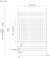
- FIG. 2 illustrates a resource grid during the duration of one slot.
- a slot includes a plurality of symbols in the time domain. For example, one slot includes 14 symbols in a normal CP case and 12 symbols in an extended CP case.
- a carrier includes a plurality of subcarriers in the frequency domain.
- a resource block (RB) may be defined by a plurality of (e.g., 12) consecutive subcarriers in the frequency domain.
- a plurality of RB interlaces (simply, interlaces) may be defined in the frequency domain. Interlace m ⁇ ⁇ 0, 1, ..., M-1 ⁇ may be composed of (common) RBs ⁇ m, M+m, 2M+m, 3M+m,... ⁇ . M denotes the number of interlaces.
- a bandwidth part may be defined by a plurality of consecutive (physical) RBs ((P)RBs) in the frequency domain and correspond to one numerology (e.g., SCS, CP length, and so on).
- a carrier may include up to N (e.g., 5) BWPs.
- Data communication may be conducted in an active BWP, and only one BWP may be activated for one UE.
- Each element in a resource grid may be referred to as a resource element (RE), to which one complex symbol may be mapped.
- RE resource element
- a user equipment receives information from a base station (BS) in downlink (DL), and the UE transmits information to the BS in uplink (UL).
- the information exchanged between the BS and UE includes data and various control information, and various physical channels/signals are present depending on the type/usage of the information exchanged therebetween.
- a physical channel corresponds to a set of resource elements (REs) carrying information originating from higher layers.
- a physical signal corresponds to a set of REs used by physical layers but does not carry information originating from the higher layers.
- the higher layers include a medium access control (MAC) layer, a radio link control (RLC) layer, a packet data convergence protocol (PDCP) layer, a radio resource control (RRC) layer, and so on.
- MAC medium access control
- RLC radio link control
- PDCP packet data convergence protocol
- RRC radio resource control
- DL physical channels include a physical broadcast channel (PBCH), a physical downlink shared channel (PDSCH), and a physical downlink control channel (PDCCH).
- DL physical signals include a DL reference signal (RS), a primary synchronization signal (PSS), and a secondary synchronization signal (SSS).
- the DL RS includes a demodulation reference signal (DM-RS), a phase tracking reference signal (PT-RS), and a channel state information reference signal (CSI-RS).
- UL physical channel include a physical random access channel (PRACH), a physical uplink shared channel (PUSCH), and a physical uplink control channel (PUCCH).
- UL physical signals include a UL RS.
- the UL RS includes a DM-RS, a PT-RS, and a sounding reference signal (SRS).
- FIG. 3 illustrates a structure of a self-contained slot.
- a frame has a self-contained structure in which a DL control channel, DL or UL data, a UL control channel, and the like may all be contained in one slot.
- the first N symbols (hereinafter, DL control region) in the slot may be used to transmit a DL control channel
- the last M symbols (hereinafter, UL control region) in the slot may be used to transmit a UL control channel.
- N and M are integers greater than or equal to 0.
- a resource region hereinafter, a data region
- a data region that is between the DL control region and the UL control region may be used for DL data transmission or UL data transmission.
- Respective sections are listed in a temporal order.
- the term 'cell/CC' in the methods described later may be used as a concept encompassing a primary cell (PCell), a secondary cell (SCell), primary SCell (PSCell), etc., which may be configured/expressed in CA/DC (dual connectivity) scenarios.
- PCell primary cell
- SCell secondary cell
- PSCell primary SCell
- a cell (or CC) that schedules a PDSCH/PUSCH (DL assignment or UL grant) may be referred to as a scheduling cell (or scheduling CC).
- a cell where the PDSCH/PUSCH scheduled through the scheduling cell is actually transmitted may be referred to as a scheduled cell (or scheduled CC).
- the scheduling cell and the scheduled cell are the same, it is called self-carrier scheduling, and when the scheduling cell and the scheduled cell are different, it is referred to as cross-carrier scheduling.
- Tables 8 and 9 illustrate information elements (IEs) related to cross-carrier scheduling specified in 3GPP TS 38.331.
- CrossCarrierSchedulingConfig field descriptions cif-Presence The field is used to indicate whether carrier indicator field is present (value true) or not (value false) in PDCCH DCI formats, see TS 38.213 [13]. If cif-Presence is set to true, the CIF value indicating a grant or assignment for this cell is 0. cif-InSchedulingCell The field indicates the CIF value used in the scheduling cell to indicate a grant or assignment applicable for this cell, see TS 38.213 [13].
- a serving cell is scheduled by a PDCCH on another (scheduling) cell.
- the network configures this field only for SCells.
- own Parameters for self-scheduling i.e., a serving cell is scheduled by its own PDCCH.
- schedulingCellId Indicates which cell signals the downlink allocations and uplink grants, if applicable, for the concerned SCell.
- the scheduling cell is part of the same cell group (i.e. MCG or SCG) as the scheduled cell.
- a cross-carrier scheduling (CCS) configuration may be configured by a higher layer parameter, CrossCarrierSchedulingConfig as shown in Tables 8 and 9.
- DCI that schedules a PDSCH or PUSCH (e.g., DCI format 0_1/0_2/1_1/1_2)
- a carrier indicator field (CIF) value is configured. This value becomes 0 for its own cell and ranges from 1 to 7 for other cells (configured by cif-InSchedulingCell).
- a configured CIF value corresponds to the value of n_CI and is used for determining PDCCH candidates.
- the UE For each DL BWP configured to a UE in a serving cell, the UE is provided by higher layers with S ⁇ 10 search space sets where, for each search space set from the S search space sets, the UE is provided the following by SearchSpace: - a PDCCH monitoring periodicity of k s slots and a PDCCH monitoring offset of o s slots, by monitoringSlotPeriodicityAndOffset or by monitoringSlotPeriodicityAndOffset-r17 - a PDCCH monitoring pattern within a slot, indicating first symbol(s) of the CORESET for PDCCH monitoring within each slot where the UE monitors PDCCH, by monitoringSymbolsWithinSlot - a duration of T s ⁇ k s indicating a number of slots that the search space set s exists by duration, or a number of slots in consecutive groups of slots where the search space set s can exist by duration-r17
- a UE determines a PDCCH monitoring occasion on an active DL BWP
- the UE monitors PDCCH candidates for search space set s for T s consecutive slots, starting from slot n s , f ⁇ , and does not monitor PDCCH candidates for search space set s for the next k s - T s consecutive slots.
- the UE monitors PDCCH candidates for search space set s within each of the T s / L s consecutive groups of slots according to monitoringSlotsWithinSlotGroup, starting from slot n s , f ⁇ , and does not monitor PDCCH candidates for search space set s for the next k s - T s consecutive slots.
- SS set #s may be configured as follows for cell #1 and cell #2.
- the UE may perform monitoring of PDCCHs at the PDCCH MOs configured in SS set #s on cell #1 as follows. Specifically, a PDCCH transmitted on cell #1 may schedule data transmitted on cell #2 (e.g., PDSCH or PUSCH). The relationship established between cell #1 and cell #2 as described above may conveniently be referred to as a CCS relationship. Additionally, monitoring PDCCHs may imply monitoring PDCCH candidates.
- a connection relationship e.g., CCS relationship
- M an integer greater than or equal to 1
- m-cc DCI which is capable of scheduling multiple cells
- s-cc DCI which is capable of scheduling schedule a single cell.
- a single cell is denoted as cell #k (where k represents a cell index or k-th cell)
- a set of two or more cells is denoted using a symbol of ⁇ ⁇ .
- ⁇ cell #1, cell #2 ⁇ means cell #1 and cell #2.
- An arbitrary set of M cells is denoted as ⁇ cell #m ⁇ , M ⁇ .
- M-cc DCI may always be defined to schedule ⁇ cell #m ⁇ , M ⁇ .
- M refers to an integer greater than or equal to 2.
- the m-cc DCI always schedules multiple cells simultaneously, and an operation of scheduling only a single cell through m-cc DCI may not be allowed.
- Cell #m may be a scheduling cell that receives the m-cc DCI (PDCCH) or a scheduled cell that is scheduled by the m-cc DCI.
- M-cc DCI may be defined to schedule either ⁇ cell #m ⁇ , M ⁇ or a single cell (ref-cc) among ⁇ cell #m ⁇ , M ⁇ .
- the m-cc DCI may schedule multiple cells simultaneously (multi-cell scheduling) or may schedule only one cell (single-cell scheduling).
- the single cell may be fixed to a specific cell (ref-cc).
- Single-cell scheduling through the m-cc DCI may not be allowed for cells other than the specific cell.
- M refers to an integer greater than or equal to 2.
- Cell #m may be a scheduling cell that receives the m-cc DCI (PDCCH) or a scheduled cell that is scheduled by the m-cc DCI.
- the reference CC (ref-cc) refers to a specific cell among ⁇ cell #m ⁇ , M ⁇ and may be predefined or configured implicitly or explicitly.
- the PDCCH monitoring operation of the UE in a cell scheduling the m-cc DCI may be defined as follows.
- a CIF may be configured in s-cc DCI.
- the CIF value allows a scheduling cell and a scheduled cell to be connected during CCS.
- the number of scheduled cells related to conventional s-cc DCI is one.
- An SS set and/or a CCS-related configuration have been made for each cell.
- m-cc DCI may simultaneously schedule a PDSCH/PUSCH for multiple cells, it may be necessary to determine which cell should be used as a reference for the SS set and/or CCS-related configuration among multiple scheduled cells.
- proposed operations will be described for cases where m-cc DCI scheduling is configured for M cells, ⁇ cell #m ⁇ , M ⁇ .
- n_CI and/or the CCE positions of PDCCH candidates (sets) may be determined (according to the methods described later).
- the PDCCH candidates (sets) determined from the CIF (and n_CI) values configured based on Criterion 1, Criterion 2, or Criterion 3 (corresponding to each n_CI value for the m-cc DCI) may be shared (SS sharing) regardless of the cell (combination) scheduled by the m-cc DCI.
- one or multiple (e.g., N) n_CI values may be determined.
- N positions of the PDCCH candidate sets, which respectively correspond to the N n_CI values are determined, m-cc DCI scheduling a specific cell (combination) corresponding to a specific CIF/n_CI value may be transmitted/received through any PDCCH candidate within the N PDCCH candidate sets.
- m-cc DCI scheduling a cell (combination) corresponding to a specific CIF/n_CI value of A may be transmitted/received through a PDCCH candidate set corresponding to a different CIF/n_CI value of B.
- CCs capable of being scheduled by m-cc DCI may also be configured to be schedulable by s-cc DCI.
- a CIF value for each CC capable of being scheduled by the m-cc DCI may be independently configured. That is, even when SS sets and/or CIF values are capable of being configured for multiple CCs according to [Criterion 1] or [Criterion 2], a CIF value for each CC may be separately configured for each of the multiple CCs. Therefore, it is necessary to distinguish between the CIF values for the m-cc DCI and the CIF values for the s-cc DCI.
- a CIF value When a CIF value is configured according to a CC combination scheduled by m-cc DCI based on [Criterion 2], one of the following methods may be applied.
- - Method 1B The CIF value may be independently configured for each CC combination. That is, the CIF value may be configured through a separate SS set configuration for each CC combination. For example, for m-cc DCI capable of scheduling up to ⁇ cell #1, cell #2, cell #3 ⁇ simultaneously, a CIF value may be configured for each actually scheduled CC combination as shown in the following example.
- the CIF value for each CC combination may be set to a CIF value of a specific representative cell (ref-cc) among cells in the corresponding CC combination.
- the ref-cc may be predefined or configured implicitly or explicitly.
- - Method for predefining or implicitly configuring ref-cc The ref-cc may be a cell with the lowest or highest index among ⁇ cell #m ⁇ , M ⁇ .
- the corresponding cell may be selected as the ref-cc.
- a scheduling cell may also be selected as the ref-cc.
- a cell that serves as the reference of CIF values may be determined as the ref-cc.
- the ref-cc may be semi-statically configured through higher layer signaling such as RRC or a MAC-CE.
- the ref-cc may also be dynamically configured through DCI.
- the signaled cell index may indicate a cell based on the pre-defined rule (or implicit configuration) described above.
- the CIF value for each CC combination may be set to a value obtained by adding an offset to a CIF value of a specific representative cell (ref-cc) among cells in the corresponding CC combination.
- the ref-cc may be defined/configured using the method described in [Method 2B], and the offset may also be predefined or separately configured (e.g., through higher layer signaling).
- the number of PDCCH candidates for each AL n for m-cc DCI may also be configured differently according to the above criteria. That is, similar to [Criterion 1], SS set #s for the m-cc DCI may be configured, and the number of PDCCH candidates for each AL n may be configured for SS set #s. Alternatively, similar to [Criterion 2], the SS set and/or the number of PDCCH candidates for each AL n may be configured for each CC combination that is simultaneously scheduled by the m-cc DCI. Alternatively, similar to [Criterion 3], the SS set and/or the number of PDCCH candidates for each AL n may be configured for each CC scheduled by the m-cc DCI.
- the SS set configuration for the m-cc DCI, and/or the number of PDCCH candidates for each AL n for the SS set, and/or the CIF value for the SS set may be configured based on the same set of CCs.
- the SS set, the number of PDCCH candidates for each AL n, and the CIF value for the m-cc DCI may be configured based on the entire set/number of CCs capable of being scheduled by the m-cc DCI.
- the SS set, the number of PDCCH candidates for each AL n, and the CIF value may be configured for each CC combination capable of being simultaneously scheduled by the m-cc DCI.
- the SS set, the number of PDCCH candidates for each AL n, and the CIF value may be configured for each CC capable of being scheduled by the m-cc DCI.
- the CIF value may be configured/reconfigured through higher layer signaling such as RRC or a MAC-CE.
- the CIF value may be configured/reconfigured based on dynamic methods such as DCI. For example, when CA is (re)configured or when each SCell is activated, the CIF value for the cells may be configured/reconfigured.
- a CIF value in DCI may be used to determine n CI (hereafter referred to as n_CI) used to determine the CCE positions of PDCCH candidates.
- n_CI may be determined through the CIF value.
- different n_CI (or CIF) values may be configured to establish different CCE positions for different scheduled CCs.
- the CIF value for m-cc DCI may be set to a single value for the entire set of scheduled CCs, configured for each combination of scheduled CCs, or configured for each scheduled CC.
- n_CI related to the CIF value may be determined by one of the following methods.
- the configuration of the CIF value may follow one of the methods described in [1].
- a set of PDCCH candidates for m-cc DCI determined from Criteria 1/2/3 described in [1] and the CIF value (and/or n_CI) based thereon does not need to be restricted to being used only for m-cc DCI transmission/reception that schedules a specific cell (or a combination of cells).
- the PDCCH candidates (or PDCCH candidate set) that may be determined by a specific combination of 'Criteria 1/2/3,' 'CIF value determination methods,' and 'n_CI value determination methods' described in [1] may be shared (SS sharing) regardless of the cells (cell combinations) scheduled by the m-cc DCI.
- the descriptions, functions, procedures, proposals, methods, and/or operation flowcharts disclosed in this document may be implemented using firmware or software, and the firmware or software may be configured to include the modules, procedures, or functions.
- Firmware or software configured to perform the descriptions, functions, procedures, proposals, methods, and/or operation flowcharts disclosed in this document may be included in the one or more processors 102 and 202 or may be stored in the one or more memories 104 and 204 and executed by the one or more processors 102 and 202.
- the descriptions, functions, procedures, proposals, methods, and/or operation flowcharts disclosed in this document may be implemented using firmware or software in the form of code, an instruction, and/or a set of instructions.
- the one or more memories 104 and 204 may be connected to the one or more processors 102 and 202 and store various types of data, signals, messages, information, programs, code, instructions, and/or commands.
- the one or more memories 104 and 204 may be configured to include read-only memories (ROMs), random access memories (RAMs), electrically erasable programmable read-only memories (EPROMs), flash memories, hard drives, registers, cash memories, computer-readable storage media, and/or combinations thereof.
- the one or more memories 104 and 204 may be located at the interior and/or exterior of the one or more processors 102 and 202.
- the one or more memories 104 and 204 may be connected to the one or more processors 102 and 202 through various technologies such as wired or wireless connection.
- the one or more transceivers 106 and 206 may be connected to the one or more antennas 108 and 208 and the one or more transceivers 106 and 206 may be configured to transmit and receive user data, control information, and/or wireless signals/channels, mentioned in the descriptions, functions, procedures, proposals, methods, and/or operation flowcharts disclosed in this document, through the one or more antennas 108 and 208.
- the one or more antennas may be a plurality of physical antennas or a plurality of logical antennas (e.g., antenna ports).
- the one or more transceivers 106 and 206 may convert received wireless signals/channels from RF band signals into baseband signals in order to process received user data, control information, and wireless signals/channels using the one or more processors 102 and 202.
- the one or more transceivers 106 and 206 may convert the user data, control information, and wireless signals/channels processed using the one or more processors 102 and 202 from the baseband signals into the RF band signals.
- the one or more transceivers 106 and 206 may include (analog) oscillators and/or filters.
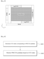
- FIG. 7 illustrates another example of a wireless device applied to the present disclosure.
- the wireless device may be implemented in various forms according to a use case/service (refer to FIG. 5 ).
- control unit 120 may be configured with a set of a communication control processor, an application processor, an electronic control unit (ECU), a graphical processing unit, and a memory control processor.
- the memory 130 may be configured with a RAM, a dynamic RAM (DRAM), a ROM, a flash memory, a volatile memory, a non-volatile memory, and/or a combination thereof.
- FIG. 8 illustrates a vehicle or an autonomous driving vehicle applied to the present disclosure.
- the vehicle or autonomous driving vehicle may be implemented as a mobile robot, a car, a train, a manned/unmanned aerial vehicle (AV), a ship, or the like.
- AV manned/unmanned aerial vehicle
- the communication unit 110 may transmit and receive signals (e.g., data and control signals) to and from external devices such as other vehicles, BSs (e.g., gNBs and road side units), and servers.
- the control unit 120 may perform various operations by controlling elements of the vehicle or the autonomous driving vehicle 100.
- the control unit 120 may include an ECU.
- the driving unit 140a may enable the vehicle or the autonomous driving vehicle 100 to drive on a road.
- the driving unit 140a may include an engine, a motor, a powertrain, a wheel, a brake, a steering device, and so on.
- the power supply unit 140b may supply power to the vehicle or the autonomous driving vehicle 100 and include a wired/wireless charging circuit, a battery, and so on.
- the autonomous driving unit 140d may implement technology for maintaining a lane on which the vehicle is driving, technology for automatically adjusting speed, such as adaptive cruise control, technology for autonomously driving along a determined path, technology for driving by automatically setting a route if a destination is set, and the like.
Landscapes
- Engineering & Computer Science (AREA)
- Signal Processing (AREA)
- Computer Networks & Wireless Communication (AREA)
- Quality & Reliability (AREA)
- Mobile Radio Communication Systems (AREA)
Applications Claiming Priority (5)
| Application Number | Priority Date | Filing Date | Title |
|---|---|---|---|
| KR20220052396 | 2022-04-27 | ||
| US202263339508P | 2022-05-08 | 2022-05-08 | |
| KR20220100896 | 2022-08-11 | ||
| KR20220124753 | 2022-09-29 | ||
| PCT/KR2023/005793 WO2023211210A1 (ko) | 2022-04-27 | 2023-04-27 | 무선 통신 시스템에서 신호를 모니터링하는 방법 및 장치 |
Publications (2)
| Publication Number | Publication Date |
|---|---|
| EP4518518A1 true EP4518518A1 (de) | 2025-03-05 |
| EP4518518A4 EP4518518A4 (de) | 2026-04-29 |
Family
ID=88519275
Family Applications (1)
| Application Number | Title | Priority Date | Filing Date |
|---|---|---|---|
| EP23796852.4A Pending EP4518518A4 (de) | 2022-04-27 | 2023-04-27 | Verfahren und vorrichtung zur überwachung eines signals in einem drahtloskommunikationssystem |
Country Status (6)
| Country | Link |
|---|---|
| US (1) | US20250301482A1 (de) |
| EP (1) | EP4518518A4 (de) |
| JP (1) | JP2025514981A (de) |
| KR (1) | KR20250007574A (de) |
| CN (1) | CN119096663A (de) |
| WO (1) | WO2023211210A1 (de) |
Families Citing this family (1)
| Publication number | Priority date | Publication date | Assignee | Title |
|---|---|---|---|---|
| CN117580171A (zh) * | 2022-08-04 | 2024-02-20 | 中国移动通信有限公司研究院 | 信道检测方法、装置、终端、网络设备及存储介质 |
Family Cites Families (3)
| Publication number | Priority date | Publication date | Assignee | Title |
|---|---|---|---|---|
| US10674519B2 (en) * | 2015-01-12 | 2020-06-02 | Lg Electronics Inc. | Method for monitoring downlink control information wireless communication system, and device therefor |
| CN113316258B (zh) * | 2018-07-20 | 2023-11-07 | 维沃移动通信有限公司 | 一种用于监听pdcch的方法、终端及网络设备 |
| US12207109B2 (en) * | 2020-06-26 | 2025-01-21 | Qualcomm Incorporated | Techniques for PDCCH monitoring aggregation |
-
2023
- 2023-04-27 CN CN202380036623.1A patent/CN119096663A/zh active Pending
- 2023-04-27 KR KR1020247038404A patent/KR20250007574A/ko active Pending
- 2023-04-27 JP JP2024563737A patent/JP2025514981A/ja active Pending
- 2023-04-27 US US18/859,366 patent/US20250301482A1/en active Pending
- 2023-04-27 EP EP23796852.4A patent/EP4518518A4/de active Pending
- 2023-04-27 WO PCT/KR2023/005793 patent/WO2023211210A1/ko not_active Ceased
Also Published As
| Publication number | Publication date |
|---|---|
| WO2023211210A1 (ko) | 2023-11-02 |
| EP4518518A4 (de) | 2026-04-29 |
| KR20250007574A (ko) | 2025-01-14 |
| CN119096663A (zh) | 2024-12-06 |
| JP2025514981A (ja) | 2025-05-13 |
| US20250301482A1 (en) | 2025-09-25 |
Similar Documents
| Publication | Publication Date | Title |
|---|---|---|
| US20260006617A1 (en) | Method and apparatus for transmitting and receiving wireless signal in wireless communication system | |
| EP4322663A1 (de) | Verfahren und vorrichtung zum senden und empfangen eines signals in einem drahtloskommunikationssystem | |
| EP4195856B1 (de) | Verfahren und vorrichtung zum senden und empfangen eines drahtlosen signals in einem drahtloskommunikationssystem | |
| US12192809B2 (en) | Method and apparatus for monitoring signals in a wireless communication system | |
| US11785539B2 (en) | Method, UE, apparatus, and storage medium for monitoring control channel in wireless communication system, and method and BS for transmitting control channel | |
| US12402145B2 (en) | Method for monitoring control channel, user equipment, device and storage medium, and method for transmitting control channel | |
| EP4518517A1 (de) | Verfahren und vorrichtung zur überwachung von signalen in einem drahtloskommunikationssystem | |
| EP4380093B1 (de) | Verfahren und vorrichtung zur überwachung eines steuersignals in einem drahtloskommunikationssystem | |
| EP4518518A1 (de) | Verfahren und vorrichtung zur überwachung eines signals in einem drahtloskommunikationssystem | |
| EP4572494A1 (de) | Verfahren und vorrichtung zum senden und empfangen von signalen in einem drahtloskommunikationssystem | |
| EP4598212A1 (de) | Verfahren und vorrichtung zur überwachung von signalen in einem drahtloskommunikationssystem | |
| US20250212229A1 (en) | Method and device for transmitting/receiving signal in wireless communication system | |
| EP4280492A1 (de) | Verfahren und vorrichtung zum senden und empfangen eines signals in einem drahtloskommunikationssystem | |
| EP4322675A1 (de) | Verfahren und vorrichtung zum senden und empfangen von signalen in einem drahtloskommunikationssystem | |
| EP4280521A1 (de) | Verfahren und vorrichtung zum senden/empfangen eines signals in einem drahtloskommunikationssystem | |
| US20250227699A1 (en) | Method and device for transmitting/receiving signals in wireless communication system | |
| EP4231577A1 (de) | Verfahren, benutzergerät, vorrichtung und speichermedium zur überwachung eines steuerkanals und basisstation zur übertragung eines steuerkanals | |
| US20250081202A1 (en) | Method, terminal, device, and storage medium for monitoring control channel, and method and base station for transmitting control channel | |
| CN117099332A (zh) | 在无线通信系统中监测信号的方法和装置 |
Legal Events
| Date | Code | Title | Description |
|---|---|---|---|
| STAA | Information on the status of an ep patent application or granted ep patent |
Free format text: STATUS: THE INTERNATIONAL PUBLICATION HAS BEEN MADE |
|
| PUAI | Public reference made under article 153(3) epc to a published international application that has entered the european phase |
Free format text: ORIGINAL CODE: 0009012 |
|
| STAA | Information on the status of an ep patent application or granted ep patent |
Free format text: STATUS: REQUEST FOR EXAMINATION WAS MADE |
|
| 17P | Request for examination filed |
Effective date: 20241122 |
|
| AK | Designated contracting states |
Kind code of ref document: A1 Designated state(s): AL AT BE BG CH CY CZ DE DK EE ES FI FR GB GR HR HU IE IS IT LI LT LU LV MC ME MK MT NL NO PL PT RO RS SE SI SK SM TR |
|
| DAV | Request for validation of the european patent (deleted) | ||
| DAX | Request for extension of the european patent (deleted) |