EP4518337A1 - Autofokuseinstellverfahren und kameravorrichtung damit - Google Patents
Autofokuseinstellverfahren und kameravorrichtung damit Download PDFInfo
- Publication number
- EP4518337A1 EP4518337A1 EP22940350.6A EP22940350A EP4518337A1 EP 4518337 A1 EP4518337 A1 EP 4518337A1 EP 22940350 A EP22940350 A EP 22940350A EP 4518337 A1 EP4518337 A1 EP 4518337A1
- Authority
- EP
- European Patent Office
- Prior art keywords
- camera device
- captured image
- objects
- size
- distance
- Prior art date
- Legal status (The legal status is an assumption and is not a legal conclusion. Google has not performed a legal analysis and makes no representation as to the accuracy of the status listed.)
- Pending
Links
Images


Classifications
-
- H—ELECTRICITY
- H04—ELECTRIC COMMUNICATION TECHNIQUE
- H04N—PICTORIAL COMMUNICATION, e.g. TELEVISION
- H04N23/00—Cameras or camera modules comprising electronic image sensors; Control thereof
- H04N23/95—Computational photography systems, e.g. light-field imaging systems
- H04N23/958—Computational photography systems, e.g. light-field imaging systems for extended depth of field imaging
- H04N23/959—Computational photography systems, e.g. light-field imaging systems for extended depth of field imaging by adjusting depth of field during image capture, e.g. maximising or setting range based on scene characteristics
-
- G—PHYSICS
- G03—PHOTOGRAPHY; CINEMATOGRAPHY; ANALOGOUS TECHNIQUES USING WAVES OTHER THAN OPTICAL WAVES; ELECTROGRAPHY; HOLOGRAPHY
- G03B—APPARATUS OR ARRANGEMENTS FOR TAKING PHOTOGRAPHS OR FOR PROJECTING OR VIEWING THEM; APPARATUS OR ARRANGEMENTS EMPLOYING ANALOGOUS TECHNIQUES USING WAVES OTHER THAN OPTICAL WAVES; ACCESSORIES THEREFOR
- G03B13/00—Viewfinders; Focusing aids for cameras; Means for focusing for cameras; Autofocus systems for cameras
- G03B13/18—Focusing aids
- G03B13/20—Rangefinders coupled with focusing arrangements, e.g. adjustment of rangefinder automatically focusing camera
-
- G—PHYSICS
- G03—PHOTOGRAPHY; CINEMATOGRAPHY; ANALOGOUS TECHNIQUES USING WAVES OTHER THAN OPTICAL WAVES; ELECTROGRAPHY; HOLOGRAPHY
- G03B—APPARATUS OR ARRANGEMENTS FOR TAKING PHOTOGRAPHS OR FOR PROJECTING OR VIEWING THEM; APPARATUS OR ARRANGEMENTS EMPLOYING ANALOGOUS TECHNIQUES USING WAVES OTHER THAN OPTICAL WAVES; ACCESSORIES THEREFOR
- G03B13/00—Viewfinders; Focusing aids for cameras; Means for focusing for cameras; Autofocus systems for cameras
- G03B13/32—Means for focusing
-
- G—PHYSICS
- G03—PHOTOGRAPHY; CINEMATOGRAPHY; ANALOGOUS TECHNIQUES USING WAVES OTHER THAN OPTICAL WAVES; ELECTROGRAPHY; HOLOGRAPHY
- G03B—APPARATUS OR ARRANGEMENTS FOR TAKING PHOTOGRAPHS OR FOR PROJECTING OR VIEWING THEM; APPARATUS OR ARRANGEMENTS EMPLOYING ANALOGOUS TECHNIQUES USING WAVES OTHER THAN OPTICAL WAVES; ACCESSORIES THEREFOR
- G03B3/00—Focusing arrangements of general interest for cameras, projectors or printers
-
- G—PHYSICS
- G06—COMPUTING OR CALCULATING; COUNTING
- G06T—IMAGE DATA PROCESSING OR GENERATION, IN GENERAL
- G06T7/00—Image analysis
- G06T7/50—Depth or shape recovery
-
- G—PHYSICS
- G06—COMPUTING OR CALCULATING; COUNTING
- G06T—IMAGE DATA PROCESSING OR GENERATION, IN GENERAL
- G06T7/00—Image analysis
- G06T7/60—Analysis of geometric attributes
-
- G—PHYSICS
- G06—COMPUTING OR CALCULATING; COUNTING
- G06V—IMAGE OR VIDEO RECOGNITION OR UNDERSTANDING
- G06V10/00—Arrangements for image or video recognition or understanding
- G06V10/70—Arrangements for image or video recognition or understanding using pattern recognition or machine learning
- G06V10/77—Processing image or video features in feature spaces; using data integration or data reduction, e.g. principal component analysis [PCA] or independent component analysis [ICA] or self-organising maps [SOM]; Blind source separation
- G06V10/776—Validation; Performance evaluation
-
- G—PHYSICS
- G06—COMPUTING OR CALCULATING; COUNTING
- G06V—IMAGE OR VIDEO RECOGNITION OR UNDERSTANDING
- G06V10/00—Arrangements for image or video recognition or understanding
- G06V10/70—Arrangements for image or video recognition or understanding using pattern recognition or machine learning
- G06V10/82—Arrangements for image or video recognition or understanding using pattern recognition or machine learning using neural networks
-
- G—PHYSICS
- G06—COMPUTING OR CALCULATING; COUNTING
- G06V—IMAGE OR VIDEO RECOGNITION OR UNDERSTANDING
- G06V20/00—Scenes; Scene-specific elements
- G06V20/60—Type of objects
-
- G—PHYSICS
- G06—COMPUTING OR CALCULATING; COUNTING
- G06V—IMAGE OR VIDEO RECOGNITION OR UNDERSTANDING
- G06V20/00—Scenes; Scene-specific elements
- G06V20/60—Type of objects
- G06V20/62—Text, e.g. of license plates, overlay texts or captions on TV images
- G06V20/625—License plates
-
- G—PHYSICS
- G06—COMPUTING OR CALCULATING; COUNTING
- G06V—IMAGE OR VIDEO RECOGNITION OR UNDERSTANDING
- G06V40/00—Recognition of biometric, human-related or animal-related patterns in image or video data
- G06V40/10—Human or animal bodies, e.g. vehicle occupants or pedestrians; Body parts, e.g. hands
- G06V40/16—Human faces, e.g. facial parts, sketches or expressions
- G06V40/161—Detection; Localisation; Normalisation
-
- H—ELECTRICITY
- H04—ELECTRIC COMMUNICATION TECHNIQUE
- H04N—PICTORIAL COMMUNICATION, e.g. TELEVISION
- H04N23/00—Cameras or camera modules comprising electronic image sensors; Control thereof
- H04N23/50—Constructional details
- H04N23/54—Mounting of pick-up tubes, electronic image sensors, deviation or focusing coils
-
- H—ELECTRICITY
- H04—ELECTRIC COMMUNICATION TECHNIQUE
- H04N—PICTORIAL COMMUNICATION, e.g. TELEVISION
- H04N23/00—Cameras or camera modules comprising electronic image sensors; Control thereof
- H04N23/50—Constructional details
- H04N23/55—Optical parts specially adapted for electronic image sensors; Mounting thereof
-
- H—ELECTRICITY
- H04—ELECTRIC COMMUNICATION TECHNIQUE
- H04N—PICTORIAL COMMUNICATION, e.g. TELEVISION
- H04N23/00—Cameras or camera modules comprising electronic image sensors; Control thereof
- H04N23/60—Control of cameras or camera modules
- H04N23/61—Control of cameras or camera modules based on recognised objects
- H04N23/611—Control of cameras or camera modules based on recognised objects where the recognised objects include parts of the human body
-
- H—ELECTRICITY
- H04—ELECTRIC COMMUNICATION TECHNIQUE
- H04N—PICTORIAL COMMUNICATION, e.g. TELEVISION
- H04N23/00—Cameras or camera modules comprising electronic image sensors; Control thereof
- H04N23/60—Control of cameras or camera modules
- H04N23/67—Focus control based on electronic image sensor signals
- H04N23/673—Focus control based on electronic image sensor signals based on contrast or high frequency components of image signals, e.g. hill climbing method
-
- H—ELECTRICITY
- H04—ELECTRIC COMMUNICATION TECHNIQUE
- H04N—PICTORIAL COMMUNICATION, e.g. TELEVISION
- H04N23/00—Cameras or camera modules comprising electronic image sensors; Control thereof
- H04N23/60—Control of cameras or camera modules
- H04N23/67—Focus control based on electronic image sensor signals
- H04N23/675—Focus control based on electronic image sensor signals comprising setting of focusing regions
-
- H—ELECTRICITY
- H04—ELECTRIC COMMUNICATION TECHNIQUE
- H04N—PICTORIAL COMMUNICATION, e.g. TELEVISION
- H04N5/00—Details of television systems
- H04N5/76—Television signal recording
- H04N5/765—Interface circuits between an apparatus for recording and another apparatus
- H04N5/77—Interface circuits between an apparatus for recording and another apparatus between a recording apparatus and a television camera
-
- G—PHYSICS
- G06—COMPUTING OR CALCULATING; COUNTING
- G06T—IMAGE DATA PROCESSING OR GENERATION, IN GENERAL
- G06T2207/00—Indexing scheme for image analysis or image enhancement
- G06T2207/30—Subject of image; Context of image processing
- G06T2207/30196—Human being; Person
- G06T2207/30201—Face
Definitions
- the present disclosure relates to autofocus adjustment technology, and more particularly, to an autofocus adjustment method and device capable of performing rapid autofocus adjustment by estimating a distance between a lens and a subject.
- image capturing devices such as charge coupled device (CCD) or complementary metal oxide semiconductor (CMOS) image sensors.
- CCD charge coupled device
- CMOS complementary metal oxide semiconductor
- the image capturing device has an autofocus (AF) function that automatically adjusts a focus. In autofocus, the focus is appropriately adjusted by driving a lens, and it is possible to acquire such a focused image.
- AF autofocus
- the focus cannot be automatically adjusted to a part desired by a user depending on a subject, which is a target.
- the user has got to perform a manipulation for focus adjustment when an image is captured, and thus, the user may not capture an image when devoting himself/herself to the image capturing itself.
- a camera includes a lens 1, an image sensor 2 capturing an image of a subject transmitted through the lens, an image processor 3 processing information on the image captured by the image sensor to generate sharpness indicating a degree of focusing of the image, a controller 5 calculating an appropriate location of the lens 1 according to the sharpness of the image processor 3, and a lens driving means 4 for moving the lens 1 to the location calculated by the controller 5.
- the controller 5 when an autofocus command is input by a user's camera manipulation or the like, the controller 5 initializes a location of the lens 1 by moving the lens 1 to an initial location, which is either the farthest distance location, which is a location closest to the image sensor (a location farthest from the subject) or the nearest distance location, which is a location farthest from the image sensor (a location closest to the subject). Thereafter, the controller 5 calculates sharpness (e.g., contrast data) at respective locations of the lens 1 while moving the lens 1 at regular intervals, and determines a location of the lens 1 having maximum sharpness of the sharpness values.
- sharpness e.g., contrast data
- the controller 5 moves the lens 1 again to the vicinity of a point having the maximum sharpness, calculates sharpness at respective locations of the lens 1 while short moving the lens 1 in a predetermined range of the vicinity of the point having the maximum sharpness, and finally determines a point having maximum sharpness of the sharpness values.
- controller 5 moves the lens 1 to the point having the maximum sharpness and then completes autofocusing.
- the autofocus function according to the related art should calculate sharpness for all regions where the location of the lens is changed, and thus, a time required for autofocusing increases, and when rapid autofocusing is performed in order to decrease the time required for autofocusing, accuracy of the autofocusing decreases.
- aspects of the present disclosure improve contrast-based autofocus performance through artificial intelligence deep learning-based thing detection technology.
- aspects of the present disclosure also improve an autofocus speed by estimating a distance between a subject and a lens using detected object information and lens/sensor information.
- aspects of the present disclosure also further improve autofocus performance using object detection information during an autofocusing operation.
- a camera device comprising a processor and a memory storing instructions executable by the processor, comprising: an image sensor capturing an image of a subject; an object identifier identifying an object included in the captured image; a distance calculator calculating a distance between the camera device and the identified object based on an occupancy percentage of the identified object in the captured image; and a controller searching for an optimal focus location where a reference value is the largest while moving a lens in a focus range including at least a focus location of the lens corresponding to the calculated distance.
- the reference value is contrast data or edge data.
- the camera device further includes a storage for storing specification information of the camera device, wherein the distance calculator acquires an angle of view in a vertical direction included in the specification information, and calculates the distance between the camera device and the identified object using the acquired angle of view in the vertical direction, a ratio of a size of the object, and a physical size of the object, and the ratio of the size of the object is a ratio of a size of the entirety or a part of the object in the vertical direction to a size of the captured image in the vertical direction.
- the object is a person, and the part of the object is a face.
- the object is a vehicle, and the part of the object is a license plate of the vehicle.
- the controller reads locus data included in the specification information stored in the storage and determines the focus range from the calculated distance with reference to the locus data, and the locus data is expressed as a focus location according to a distance to the subject at a specific zoom magnification.
- the object is an object selected among a plurality of objects included in the captured image.
- the selected object is an object closest to a center of the captured image among the plurality of objects.
- the plurality of objects include different types of two or more objects, and the selected object is an object whose size of the entirety or a part is standardized among the two or more objects.
- the identification of the object is performed by a deep learning-based thing detection algorithm, and accuracy for the identification of the object is obtained as a result of the identification, and the selected object is an object having higher accuracy among the plurality of objects.
- the controller sets a window in the captured image and searches for the optimal focus location in the set window, and the set window is set around the selected object.
- the identification of the object is performed by a deep learning-based thing detection algorithm, and accuracy for the identification of the object is obtained as a result of the identification, and as the accuracy becomes higher, the focus range is set to be narrower, and as the accuracy becomes lower, the focus range is set to be wider.
- the controller sets a window in the captured image and searches for the optimal focus location in the set window, and when there is movement of the identified object, the controller sets the window in consideration of the movement of the object.
- the controller changes a size of the window when the movement of the object is movement of the object that becomes close to or far from the image sensor.
- the controller moves and set the window to a predicted location according to the movement when the movement of the object is movement of the object to another location in the captured image.
- an autofocus adjustment method performed by instructions under the control of a processor in a camera device comprising the processor and a memory storing the instructions executable by the processor, the autofocus adjustment method including: capturing an image of a subject; identifying an object included in the captured image; calculating a distance between the camera device and the identified object based on an occupancy percentage of the identified object in the captured image; and moving a lens in a focus range including at least a focus location of the lens corresponding to the calculated distance; and searching for an optimal focus location where a reference value is the largest while moving the lens.
- the autofocus adjustment method further includes, acquiring an angle of view in a vertical direction included in specification information of the camera device; and calculating the distance between the camera device and the identified object using the acquired angle of view in the vertical direction, a ratio of a size of the object, and a physical size of the object, wherein the ratio of the size of the object is a ratio of a size of the entirety or a part of the object in the vertical direction to a size of the captured image in the vertical direction.
- the object is an object selected among a plurality of objects included in the captured image, and the selected object is an object closest to a center of the captured image among the plurality of objects.
- the object is an object selected among a plurality of objects included in the captured image, the plurality of objects include different types of two or more objects, and the selected object is an object whose size of the entirety or a part is standardized among the two or more objects.
- the identification of the object is performed by a deep learning-based thing detection algorithm, and accuracy for the identification of the object is obtained as a result of the identification, and an object having higher accuracy among a plurality of objects included in the captured image is selected as the identified object.
- GUI graphic user interface
- FIG. 2 is a block diagram illustrating a configuration of a camera device 100 according to an embodiment of the present disclosure.
- the camera device 100 may be configured to include a lens 105, an image sensor 110, an image processor 115, a lens driver 120, an object identifier 130, an artificial intelligence (AI) device 20, a controller 150, a distance calculator 160, and a storage 170.
- AI artificial intelligence
- the controller 150 may serve as a controller controlling operations of other components of the camera device 100, and may generally be implemented as a central processing unit (CPU), a microprocessor, or the like.
- the storage 170 is a storage medium storing a result performed by the controller 150 or data necessary for an operation of the controller 150, and may be implemented as a volatile memory or a non-volatile memory.
- the lens 105 may be opened or closed by a shutter (not illustrated), and introduces light reflected from a subject in a state where the shutter is opened.
- the lens 105 may move (forward or backward) in a predetermined range by the lens driver 120 for focus adjustment.
- the lens driver 120 may generally be implemented as a rotary motor, a linear motor, or various other types of actuators.
- the image sensor 110 captures an image in a manner of capturing light input to the lens 105 in the state where the shutter is opened and outputting the captured light as an electrical signal.
- Such an image may be displayed as an analog signal or a digital signal, but recently, it is general that such an image is displayed as a digital signal.
- the digital signal is pre-processed by the image processor or an image signal processor (ISP) and then provided to the controller 150, and is temporarily or permanently stored in the storage 170.
- ISP image signal processor
- the object identifier 130 identifies an object included in the captured image.
- the object refers to a target that may be distinguished from a background and has independent movement, such as a person or a thing included in an image. Such identification of the object may be performed through a deep learning algorithm by the Al device 20.
- the Al device 20 will be described in more detail later with reference to FIGS. 8A and 8B .
- the object identified by the object identifier 130 may generally be defined by an object ID, a type of object, an object probability, an object size, and the like.
- the object ID is an arbitrary identifier indicating whether or not the object is identical, and the type of object indicates a class that may be distinguished by a person, such as a person, an animal, and a vehicle.
- the object probability is a numerical value indicating accuracy with which the object would have been correctly identified. For example, when a type of specific object is a person and the object probability is 80%, it means that a probability that the object will be the person is 80%
- the distance calculator 160 calculates a distance between the camera device and the identified object based on an occupancy percentage of the identified object in the captured image.
- the distance calculator 160 may also directly measure a distance to the identified object like a laser-based distance measuring device.
- the present disclosure will be described on the assumption that the distance is calculated only by analysis of the image such as the occupancy percentage of the object in the image.
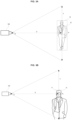
- FIGS. 3A to 3C are diagrams illustrating examples of calculating distances to specific objects using only images captured by the camera device 100. Among them,
- FIG. 3A illustrates an example of calculating a distance between the camera device 100 and a person on the basis of an entire size of an object, for example, the person, included in the image.
- a value to be calculated is a distance D between the camera device 100 and the person 10.
- an angle of view of the camera device 100 in a vertical direction is expressed as ⁇
- a size in the vertical direction that may be image-captured by the camera device 100 according to the angle of view ⁇ is expressed as V.
- the size of the object such as the person may be displayed in the form of a box 15 by the object identifier 130 described above, and the size of the object in the vertical direction may be defined as H.
- the angle of view ⁇ of the camera device 100 may be obtained from specification information of the camera device 100, and the specification information may be stored in advance in the storage 170.
- Equation 2 is satisfied between the distance D and the size V in the vertical direction that may be image-captured.
- ⁇ refers to the angle of view of the camera device 100 in the vertical direction, more precisely, an angle of view in the vertical direction at a specific magnification.
- V 2 ⁇ D ⁇ tan ⁇ 2
- Equation 3 50 ⁇ H P ⁇ tan ⁇ 2
- the angle of view ⁇ may be known from specifications of the camera device 100, and the ratio P of the size of the object may be simply known by confirming the image captured by the image sensor 110. For example, when the number of vertical pixels in the captured image is 1080 and the number of vertical pixels occupied by a specific object in the captured image is 216, the ratio P of the size of the object will be 20.
- H corresponding to the height of the person may be considered to be approximately 1 m to 2 m, and thus, a minimum value of D will be 9.25m and a maximum value of D will be 18.5m.
- a more accurate calculation may be made by additionally reflecting a location of the object, lens distortion information, and the like, and in the case of a zoom camera whose angle of view changes, the distance may be rapidly calculated by storing distance values for each object size in a table according to each magnification.
- distance calculation is enough to narrow a focus search range during the autofocusing operation, and may thus be sufficiently utilized even though accuracy is not perfect.
- the distance D between the camera device 100 and the object 10 has been calculated on the basis of the entire size of the object such as the height of the person.
- the height of the person may have considerably various ranges and may change depending on a posture even in the case of the same person. Therefore, in FIG. 3B , the distance D may be calculated by applying Equation 3 described above on the basis of a size H a of a part of the object, for example, a face 17 of the person, in the vertical direction.
- a size H a of a part of the object for example, a face 17 of the person, in the vertical direction.
- a face 17 of the person feature points of the face such as eyes, a nose, and a mouth are clear and a deviation between sizes of the feature points is small, and thus, a more accurate result may be obtained.
- the distance D may be calculated by applying Equation 3 described above on the basis of a size H b of the license plate 19 of the vehicle in the vertical direction. In this case, accuracy of the calculated distance D will be higher than that in other embodiments.
- the controller 150 drives the lens driver 120 so as to move the lens in a focus range including at least a focus location of the lens 105 corresponding to the distance D calculated by the distance calculator 160.
- the controller 150 searches for an optimal focus location where a reference value is largest in the focus range.
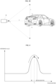
- FIG. 4 is a diagram illustrating a process of finding the optimal focus location F o where the reference value is the largest as described above.
- the controller 150 continuously checks a change in the reference value while the focus location of the lens 105 moves.
- the controller first finds a peak section including a point where a peak value occurs (peak point) while moving in a relatively large step. Once the peak section is found, the controller may find a final peak point k while finely moving in the peak section, and a focus location at such a peak point k is set to the optimal focus location F o .
- controller 150 drives the lens driver 120 to move the lens 105 to the optimal focus location F o , such that the autofocusing operation is completed.
- Contrast data or edge data may generally be used as the reference value.
- Such contrast data may be defined as the sum of absolute differences (SAD) between pixels in a region of interest and surrounding pixels, and the larger the SAD, the more the edge data or the details of the image.
- SAD absolute differences
- the more accurate the focus the higher the value of the edge data.
- FIG. 5 is graphs of locus data illustrating a change in focus location at a specific magnification.
- locus data may be stored in advance in the storage 170 as specification information of the camera device 100.
- a horizontal axis is a zoom magnification of the camera device 100
- a vertical axis is a focus location of the camera device 100.
- FIG. 5 exemplarily illustrates only locus data (solid line) at an infinite Inf distance and locus data (dotted line) at a distance of 1.5 m.
- the focus location at the distance of 1.5 m is approximately 300
- the focus location at the infinite distance is approximately 500.
- the optimal focus location should be searched from a very close distance to the infinite distance, that is, in a range N of 0 to 500.
- the optimal focus location needs to be searched only in a reduced margin range, that is, a focus range M, including at least the calculated focus location b, and thus, a time required for the autofocusing operation decreases, such that rapid autofocusing becomes possible.
- an object that is a basis for calculating the distance D in the captured image is some objects or one object selected among the plurality of objects.
- the selected object may be an object closest to the center of the captured image among the plurality of objects.
- FIG. 6 is a diagram illustrating an example of calculating a distance D on the basis of an object close to the center of an image among a plurality of objects.
- the camera device 100 When a camera simply performs autofocus on the basis of the center of the image, in the case where there are no objects at the center p c of the image, things are out of focus through the autofocus, such that a blurry image may be obtained.
- the camera device 100 includes the object identifier 130 as illustrated in FIG. 2 , it is preferable to calculate the distance D on the basis of an object p o selected among the plurality of objects.
- a user places a target for which he/she wants to capture an image at the center of the image. Therefore, in an embodiment, the object p o closest to the center p c of the image among the plurality of objects is selected.
- all of the plurality of objects are persons in FIG. 6 , but persons and other things may be mixed in the image. That is, when the plurality of objects in the image include different types of two or more objects, the basis for selecting the object may be differently determined. For example, in an image in which the object having the part (e.g., the license plate) having the standardized size as illustrated in FIG. 3C and the other object are mixed, the distance D may be calculated on the basis of the object having the part of the standardized size rather than whether or the object is close to the center of the image.
- the part e.g., the license plate
- the object identifier 130 may identify the object using a deep learning-based thing detection algorithm, and as a result, obtain accuracy of object identification, that is, an object probability.
- the distance D may be calculated on the basis of object having the highest object probability or accuracy among the plurality of objects in the image. This is to prevent the distance D from being completely incorrectly calculated to hinder a rapid autofocusing operation when the type of object is misjudged.
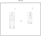
- FIGS. 7A and 7B are diagrams illustrating a method of setting an AF window used when a controller 150 determines a location of a lens 11 having maximum sharpness from contrast data.
- FIG. 6 is used in a process of selecting the object as the basis for calculating the distance D by the distance calculator 160, while FIGS. 7A and 7B are used in a process of searching for the optimal focus location on the basis of the contrast data subsequently performed by the controller 150 and are thus distinguished from FIG. 6 .
- an optimal focus search is performed in an AF window set in the image rather than the entire image. That is, the controller 150 computes the contrast data in order to search for the optimal focus location in the AF window. Accuracy of the search for the optimal focus location may change depending on how such an AF window is set. For example, when the AF window is simply set at the center p c of the image as illustrated in FIG. 7A , two objects may be included in the AF window, and when edge data are more in an object of a distant location than in an object of a close location, the optimal focus location may be misjudged.
- the object identifier 130 identifies the objects by the deep learning-based thing detection algorithm and already knows size information of the objects, and thus, regions 31 and 32 occupied by respective objects may be set as the AF window or a region 31 of one of the respective objects may be set as the AF window.
- Such object-based AF window setting helps increase accuracy and rapidness of the autofocus.
- the accuracy of the object that is, the object probability
- the focus range is set to be narrower (the margin is set to be smaller), and as the accuracy becomes lower, the focus range is set to be wider (the margin is set to be larger).
- Such a variable margin changes depending on the object probability according to the deep learning-based thing detection algorithm, and may thus be appropriately adjusted according to situations of the objects in the image.
- an embodiment of the present disclosure proposes a method of setting an AF window at a predicted location to be moved according to a moving speed of a moving object.
- the controller 150 sets an AF window in the captured image and searches for the optimal focus location in the set AF window.
- the controller 150 sets the AF window in consideration of the movement of the object.
- the controller 150 changes and sets a size of the AF window when the movement of the object is movement of the object that becomes close to or far from the image sensor 110 (close or far movement).
- the size of the AF window may be significantly changed in advance, and when the object moves to become far from the image sensor 110, the size of the AF window may be significantly changed in advance.
- the controller 150 may move and set the AF window in advance to a predicted location according to the movement.
- the controller 150 may change a size and a location of the AF window in consideration of both the close or far movement and the two-dimensional movement.
- FIG. 8A is a block diagram of an artificial intelligence (AI) device in accordance with an exemplary embodiment of the present disclosure
- FIG. 8B is an example of a deep neural network (DNN) model to which the present disclosure may be applied.
- AI artificial intelligence
- DNN deep neural network
- An Al device 20 may include a communication device including an Al module capable of performing Al processing, a server including the Al module, or the like.
- the Al device 20 may be included as at least a part in a communication device and may be provided to perform at least some of Al processing together.
- the Al device 20 may include an Al processor 21, a memory 25 and/or a communication unit 27.
- the Al device 20 is a computing device capable of learning a neural network, and may be implemented as various electronic devices such as a server, a desktop PC, a notebook PC, and a tablet PC.
- the Al processor 21 may learn a neural network by using a program stored in the memory 25.
- the Al processor 21 may learn a neural network for recognizing object-related data.
- the neural network for recognizing object-related data may be designed to simulate a human brain structure on a computer, and may include a plurality of network nodes with weights that simulate neurons of the human neural network.
- the plurality of network modes may exchange data according to their respective connection relationships such that neurons may simulate the synaptic activity of neurons for sending and receiving signals through synapses.
- the neural network may include a deep learning model developed from a neural network model. In the deep learning model, a plurality of network nodes may be located in different layers and exchange data according to a convolutional connection relationship.
- neural network models include various deep learning techniques, such as deep neural networks (DNN), convolutional deep neural networks (CNN), recurrent neural networks (RNN), restricted Boltzmann machine (RBM), deep belief networks (DBN), or Deep Q-Networks, and may be applied to fields such as computer vision, speech recognition, natural language processing, and speech/signal processing.
- DNN deep neural networks
- CNN convolutional deep neural networks
- RNN recurrent neural networks
- RBM restricted Boltzmann machine
- DNN deep belief networks
- Deep Q-Networks Deep Q-Networks
- the processor that performs the functions as described above may be a general-purpose processor (e.g., CPU), but may be an Al dedicated processor (e.g., GPU) for artificial intelligence learning.
- the memory 25 may store various programs and data required for the operation of the Al device 20.
- the memory 25 may be implemented by a non-volatile memory, a volatile memory, a flash memory, a hard disk drive (HDD), a solid state drive (SDD), or the like.
- the memory 25 is accessed by the Al processor 21, and data read/write/edit/delete/update by the Al processor 21 may be performed.
- the memory 25 may store a neural network model (e.g., a deep learning model 26) generated through a learning algorithm for data classification/recognition in accordance with an exemplary embodiment of the present disclosure.
- a neural network model e.g., a deep learning model 26
- the Al processor 21 may include a data learning unit 22 for learning a neural network for data classification/recognition.
- the data learning unit 22 may learn a criterion on which training data to use and how to classify and recognize data using the training data in order to determine data classification/recognition.
- the data learning unit 22 may learn the deep learning model by acquiring training data to be used for learning and applying the acquired training data to the deep learning model.
- the data learning unit 22 may be manufactured in the form of at least one hardware chip and mounted on the Al device 20.
- the data learning unit 22 may be manufactured in the form of a dedicated hardware chip for artificial intelligence (AI), or may be manufactured as a part of a general-purpose processor (CPU) or a dedicated graphics processor (GPU) and mounted on the Al device 20.
- AI artificial intelligence
- CPU general-purpose processor
- GPU dedicated graphics processor
- the data learning unit 22 may be implemented as a software module.
- the software module When implemented as a software module (or a program module including an instruction), the software module may be stored in a non-transitory computer-readable medium. In this case, at least one software module may be provided by an operating system (OS) or an application.
- OS operating system
- application application
- the data learning unit 22 may include a training data acquisition unit 23 and a model learning unit 24.
- the training data acquisition unit 23 may acquire training data requested for the neural network model for classifying and recognizing data.
- the training data acquisition unit 23 may acquire object data and/or sample data for input into the neural network model as training data.
- the model learning unit 24 may learn to have a criterion for determining how the neural network model classifies predetermined data by using the acquired training data.
- the model learning unit 24 may train the neural network model through supervised learning using at least a portion of the training data as a criterion for determination.
- the model learning unit 24 may train the neural network model through unsupervised learning to discover a criterion by self-learning using the training data without being supervised.
- the model learning unit 24 may train the neural network model through reinforcement learning by using feedback on whether the result of situation determination based on the learning is correct.
- the model learning unit 24 may train the neural network model by using a learning algorithm including an error back-propagation method or a gradient decent method.
- the model learning unit 24 may store the learned neural network model in the memory.
- the model learning unit 24 may store the learned neural network model in a memory of a server connected to the Al device 20 via a wired or wireless network.
- the data learning unit 22 may further include a training data preprocessor (not illustrated) and a training data selection unit (not illustrated) in order to improve the analysis result of the recognition model or to save resources or time required for generating the recognition model.
- the training data preprocessor may preprocess the acquired data such that the acquired data may be used for learning to determine the situation. For example, the training data preprocessor may process the acquired data into a preset format such that the model learning unit 24 may use the training data acquired for learning for image recognition.
- the training data selection unit may select data required for training from the training data acquired by the training data acquisition unit 23 or the training data preprocessed by the preprocessor.
- the selected training data may be provided to the model learning unit 24.
- the training data selection unit may select only data on an object included in a specific region as the training data by detecting the specific region among images acquired through a camera device.
- the data learning unit 22 may further include a model evaluation unit (not illustrated) to improve the analysis result of the neural network model.
- the model evaluation unit may input evaluation data to the neural network model, and may cause the model learning unit 24 to retrain the neural network model when an analysis result output from the evaluation data does not satisfy a predetermined criterion.
- the evaluation data may be predefined data for evaluating the recognition model.
- the model evaluation unit may evaluate the model as not satisfying a predetermined criterion when, among the analysis results of the trained recognition model for the evaluation data, the number or ratio of evaluation data for which the analysis result is inaccurate exceeds a preset threshold.
- the communication unit 27 may transmit the Al processing result by the Al processor 21 to an external communication device.
- the deep neural network is an artificial neural network (ANN) including several hidden layers between an input layer and an output layer.
- the deep neural network may model complex non-linear relationships, as in typical artificial neural networks.
- each object may be represented as a hierarchical configuration of basic image elements.
- the additional layers may aggregate the characteristics of the gradually gathered lower layers.
- the artificial neural network is called 'deep', and machine learning paradigm that uses such a sufficiently deepened artificial neural network as a learning model is called deep learning.
- the sufficiently deep artificial neural network used for the deep learning is commonly referred to as the deep neural network (DNN).
- data required to train an object data generation model may be input to the input layer of the DNN, and meaningful evaluation data that may be used by a user may be generated through the output layer while the data pass through the hidden layers.
- the accuracy of the evaluation data trained through the neural network model can be represented by a probability, and the higher the probability, the higher the accuracy of the evaluated result.
- FIG. 9 is a block diagram illustrating the hardware configuration of a computing device 200 that implements a camera device 100.
- a computing device 200 includes a bus 220, a processor 230, a memory 240, a storage 250, an input/output interface 210, and a network interface 260.
- the bus 220 is a path for the transmission of data between the processor 230, the memory 240, the storage 250, the input/output interface 210, and the network interface 260.
- the processor 230 is an arithmetic processing unit such as a central processing unit (CPU) or a graphics processing unit (GPU).
- the memory 240 is a memory such as a random-access memory (RAM) or a read-only memory (ROM).
- the storage 250 is a storage device such as a hard disk, a solid state drive (SSD), or a memory card.
- the storage 250 may also be a memory such as a RAM or a ROM.
- the input/output interface 210 is an interface for connecting the computing device 200 and an input/output device.
- a keyboard or a mouse is connected to the input/output interface 210.
- the network interface 260 is an interface for communicatively connecting the computing device 200 and an external device to exchange transport packets with each other.
- the network interface 260 may be a network interface for connection to a wired line or for connection to a wireless line.
- the computing device 200 may be connected to another computing device 200-1 via a network 50.
- the storage 250 stores program modules that implement the functions of the computing device 200.
- the processor 230 implements the functions of the computing device 200 by executing the program modules.
- the processor 230 may read the program modules into the memory 240 and may then execute the program modules.
- the hardware configuration of the computing device 200 is not particularly limited to the construction illustrated in FIG. 9 .
- the program modules may be stored in the memory 240.
- the computing device 200 may not include the storage 250.
- the camera device 100 may at least include the processor 230 and the memory 240, which stores instructions that can be executed by the processor 230.
- the camera device 100 of FIG. 2 in particular, can be driven by executing instructions including a variety of functional blocks or steps included in the camera device 100, via the processor 230.
- FIG. 10 is a schematic flowchart illustrating an autofocus adjustment method in the camera device 100 according to an embodiment of the present disclosure.
- the image sensor 110 captures an image of the subject (S51).
- the object identifier 130 identifies an object included in the captured image using the deep learning-based thing detection algorithm (S52).
- the distance calculator 160 calculates a distance between the camera device and the identified object based on an occupancy percentage of the identified object in the captured image (S53).
- the controller 150 moves the lens in a focus range including at least a focus location of the lens corresponding to the calculated distance (S54).
- controller 150 searches for an optimal focus location at which a reference value is the largest while the lens is moving (S55).
- the distance calculator 160 acquires an angle of view in the vertical direction included in specification information of the camera device, and calculates the distance between the camera device and the identified object using the acquired angle of view in the vertical direction, a ratio of a size of the object, and a physical size of the object.
- the ratio of the size of the object may be a ratio of a size of the entirety or a part of the object in the vertical direction to a size of the captured image in the vertical direction.
- the object may be an object selected among a plurality of objects included in the captured image, and the selected object may be an object closest to the center of the captured image among the plurality of objects.
- the object may be an object selected among a plurality of objects included in the captured image, the plurality of objects may include different types of two or more objects, and the selected object may be an object whose size of the entirety or a part is standardized among the two or more objects.
- the identification of the object may be performed by the deep learning-based thing detection algorithm, accuracy for the identification of the object may be obtained as a result of the identification, and an object having higher accuracy among the plurality of objects included in the captured image may be selected as the identified object.
Landscapes
- Engineering & Computer Science (AREA)
- Multimedia (AREA)
- Physics & Mathematics (AREA)
- General Physics & Mathematics (AREA)
- Theoretical Computer Science (AREA)
- Signal Processing (AREA)
- Computer Vision & Pattern Recognition (AREA)
- Evolutionary Computation (AREA)
- Computing Systems (AREA)
- Health & Medical Sciences (AREA)
- General Health & Medical Sciences (AREA)
- Artificial Intelligence (AREA)
- Databases & Information Systems (AREA)
- Medical Informatics (AREA)
- Software Systems (AREA)
- Geometry (AREA)
- Oral & Maxillofacial Surgery (AREA)
- Human Computer Interaction (AREA)
- Studio Devices (AREA)
Applications Claiming Priority (2)
| Application Number | Priority Date | Filing Date | Title |
|---|---|---|---|
| KR1020220053253A KR20230153626A (ko) | 2022-04-29 | 2022-04-29 | 오토 포커스 조절 방법 및 이를 이용한 카메라 장치 |
| PCT/KR2022/007016 WO2023210856A1 (ko) | 2022-04-29 | 2022-05-17 | 오토 포커스 조절 방법 및 이를 이용한 카메라 장치 |
Publications (2)
| Publication Number | Publication Date |
|---|---|
| EP4518337A1 true EP4518337A1 (de) | 2025-03-05 |
| EP4518337A4 EP4518337A4 (de) | 2026-04-08 |
Family
ID=88518980
Family Applications (1)
| Application Number | Title | Priority Date | Filing Date |
|---|---|---|---|
| EP22940350.6A Pending EP4518337A4 (de) | 2022-04-29 | 2022-05-17 | Autofokuseinstellverfahren und kameravorrichtung damit |
Country Status (5)
| Country | Link |
|---|---|
| US (1) | US20240223885A1 (de) |
| EP (1) | EP4518337A4 (de) |
| KR (1) | KR20230153626A (de) |
| CN (1) | CN117957850A (de) |
| WO (1) | WO2023210856A1 (de) |
Families Citing this family (3)
| Publication number | Priority date | Publication date | Assignee | Title |
|---|---|---|---|---|
| DE102022207014A1 (de) * | 2022-07-08 | 2024-01-11 | Arnold & Richter Cine Technik Gmbh & Co. Betriebs Kg | Kamera-Assistenzsystem |
| JP2024164524A (ja) * | 2023-05-15 | 2024-11-27 | キヤノン株式会社 | 制御装置、撮像装置、制御方法およびプログラム |
| KR20250083640A (ko) * | 2023-12-01 | 2025-06-10 | 한화비전 주식회사 | 영상 촬영 장치 및 방법 |
Family Cites Families (11)
| Publication number | Priority date | Publication date | Assignee | Title |
|---|---|---|---|---|
| US5764290A (en) * | 1993-11-26 | 1998-06-09 | Sony Corporation | Flange-back adjusting method and apparatus for a video camera using an inner focus lens assembly |
| JP4207980B2 (ja) * | 2006-06-09 | 2009-01-14 | ソニー株式会社 | 撮像装置、および撮像装置制御方法、並びにコンピュータ・プログラム |
| JP2009031760A (ja) | 2007-07-04 | 2009-02-12 | Sanyo Electric Co Ltd | 撮像装置及びオートフォーカス制御方法 |
| KR20100068717A (ko) * | 2008-12-15 | 2010-06-24 | 삼성전자주식회사 | 촬영 장치에서의 오토포커스 방법 및 장치 |
| US9077890B2 (en) * | 2011-02-24 | 2015-07-07 | Qualcomm Incorporated | Auto-focus tracking |
| US20130258167A1 (en) * | 2012-03-28 | 2013-10-03 | Qualcomm Incorporated | Method and apparatus for autofocusing an imaging device |
| KR101758684B1 (ko) * | 2012-07-23 | 2017-07-14 | 한화테크윈 주식회사 | 객체 추적 장치 및 방법 |
| KR101932546B1 (ko) * | 2014-09-30 | 2018-12-27 | 한화테크윈 주식회사 | Af 카메라에 있어서, 최적의 주밍 속도를 찾는 장치 및 방법 |
| US9854155B1 (en) * | 2015-06-16 | 2017-12-26 | Amazon Technologies, Inc. | Determining camera auto-focus settings |
| KR102407624B1 (ko) * | 2015-10-06 | 2022-06-10 | 삼성전자주식회사 | 전자 장치의 영상 처리 방법 및 그 전자 장치 |
| EP3936917B1 (de) * | 2020-07-09 | 2024-05-01 | Beijing Xiaomi Mobile Software Co., Ltd. | Digitale bilderfassungsvorrichtung und autofokusverfahren |
-
2022
- 2022-04-29 KR KR1020220053253A patent/KR20230153626A/ko active Pending
- 2022-05-17 CN CN202280060550.5A patent/CN117957850A/zh active Pending
- 2022-05-17 EP EP22940350.6A patent/EP4518337A4/de active Pending
- 2022-05-17 WO PCT/KR2022/007016 patent/WO2023210856A1/ko not_active Ceased
-
2024
- 2024-03-11 US US18/601,362 patent/US20240223885A1/en active Pending
Also Published As
| Publication number | Publication date |
|---|---|
| EP4518337A4 (de) | 2026-04-08 |
| KR20230153626A (ko) | 2023-11-07 |
| US20240223885A1 (en) | 2024-07-04 |
| WO2023210856A1 (ko) | 2023-11-02 |
| CN117957850A (zh) | 2024-04-30 |
Similar Documents
| Publication | Publication Date | Title |
|---|---|---|
| US12314342B2 (en) | Object recognition method and apparatus | |
| EP4518337A1 (de) | Autofokuseinstellverfahren und kameravorrichtung damit | |
| US20250054187A1 (en) | Main subject determining apparatus, image capturing apparatus, main subject determining method, and storage medium | |
| CN106657812B (zh) | 一种相机系统及动态物件分类方法 | |
| KR102548732B1 (ko) | 신경망 학습 방법 및 이를 적용한 장치 | |
| KR101441333B1 (ko) | 인체 부분 검출 장치 및 그 방법 | |
| CN110163114A (zh) | 一种人脸角度及人脸模糊度分析方法、系统和计算机设备 | |
| CN115661246B (zh) | 一种基于自监督学习的姿态估计方法 | |
| US12417634B2 (en) | Occlusion detection and object coordinate correction for estimating the position of an object | |
| CN111881849A (zh) | 图像场景检测方法、装置、电子设备及存储介质 | |
| CN119729207A (zh) | 一种基于机器视觉的摄影聚焦控制方法 | |
| US20230386185A1 (en) | Statistical model-based false detection removal algorithm from images | |
| CN111598065A (zh) | 深度图像获取方法及活体识别方法、设备、电路和介质 | |
| US12184966B2 (en) | Method and electronic device for photographing object for identification of companion animal | |
| CN119149856B (zh) | 一种用于复杂背景下的无人机检测跟踪方法及装置 | |
| US20230073357A1 (en) | Information processing apparatus, machine learning model, information processing method, and storage medium | |
| CN119788969B (zh) | 用于扫码摄像头角度自适应调节方法、系统及电子设备 | |
| CN112784494B (zh) | 假阳性识别模型的训练方法、目标识别方法及装置 | |
| US20230386164A1 (en) | Method for training an object recognition model in a computing device | |
| CN117475358B (zh) | 一种基于无人机视觉的碰撞预测方法及装置 | |
| KR20230166865A (ko) | 영상에서 통계모델기반 오검출 제거 알고리즘 | |
| KR20230131601A (ko) | 파노라마 감시 영상의 생성 | |
| CN117523428B (zh) | 基于飞行器平台的地面目标检测方法和装置 | |
| US20250184606A1 (en) | Image capturing apparatus and method | |
| KR20240008091A (ko) | 디포커스 학습 장치 및 이와 통신하는 카메라 장치 |
Legal Events
| Date | Code | Title | Description |
|---|---|---|---|
| STAA | Information on the status of an ep patent application or granted ep patent |
Free format text: STATUS: THE INTERNATIONAL PUBLICATION HAS BEEN MADE |
|
| PUAI | Public reference made under article 153(3) epc to a published international application that has entered the european phase |
Free format text: ORIGINAL CODE: 0009012 |
|
| STAA | Information on the status of an ep patent application or granted ep patent |
Free format text: STATUS: REQUEST FOR EXAMINATION WAS MADE |
|
| 17P | Request for examination filed |
Effective date: 20240718 |
|
| AK | Designated contracting states |
Kind code of ref document: A1 Designated state(s): AL AT BE BG CH CY CZ DE DK EE ES FI FR GB GR HR HU IE IS IT LI LT LU LV MC MK MT NL NO PL PT RO RS SE SI SK SM TR |
|
| DAV | Request for validation of the european patent (deleted) | ||
| DAX | Request for extension of the european patent (deleted) | ||
| REG | Reference to a national code |
Ref country code: DE Ref legal event code: R079 Free format text: PREVIOUS MAIN CLASS: H04N0023600000 Ipc: H04N0023670000 |
|
| A4 | Supplementary search report drawn up and despatched |
Effective date: 20260309 |
|
| RIC1 | Information provided on ipc code assigned before grant |
Ipc: H04N 23/67 20230101AFI20260303BHEP Ipc: H04N 23/60 20230101ALI20260303BHEP Ipc: G06V 20/60 20220101ALI20260303BHEP Ipc: G06V 10/82 20220101ALI20260303BHEP Ipc: H04N 23/61 20230101ALI20260303BHEP |