EP4518303A1 - Image management apparatus, method of controlling image management apparatus, and computer program - Google Patents
Image management apparatus, method of controlling image management apparatus, and computer program Download PDFInfo
- Publication number
- EP4518303A1 EP4518303A1 EP24195416.3A EP24195416A EP4518303A1 EP 4518303 A1 EP4518303 A1 EP 4518303A1 EP 24195416 A EP24195416 A EP 24195416A EP 4518303 A1 EP4518303 A1 EP 4518303A1
- Authority
- EP
- European Patent Office
- Prior art keywords
- image
- analysis
- management apparatus
- failure
- result
- Prior art date
- Legal status (The legal status is an assumption and is not a legal conclusion. Google has not performed a legal analysis and makes no representation as to the accuracy of the status listed.)
- Pending
Links
Images






Classifications
-
- H—ELECTRICITY
- H04—ELECTRIC COMMUNICATION TECHNIQUE
- H04N—PICTORIAL COMMUNICATION, e.g. TELEVISION
- H04N1/00—Scanning, transmission or reproduction of documents or the like, e.g. facsimile transmission; Details thereof
- H04N1/32—Circuits or arrangements for control or supervision between transmitter and receiver or between image input and image output device, e.g. between a still-image camera and its memory or between a still-image camera and a printer device
- H04N1/32609—Fault detection or counter-measures, e.g. original mis-positioned, shortage of paper
- H04N1/32625—Fault detection
- H04N1/32641—Fault detection of transmission or transmitted data, e.g. interruption or wrong number of pages
-
- H—ELECTRICITY
- H04—ELECTRIC COMMUNICATION TECHNIQUE
- H04N—PICTORIAL COMMUNICATION, e.g. TELEVISION
- H04N1/00—Scanning, transmission or reproduction of documents or the like, e.g. facsimile transmission; Details thereof
- H04N1/00127—Connection or combination of a still picture apparatus with another apparatus, e.g. for storage, processing or transmission of still picture signals or of information associated with a still picture
- H04N1/00204—Connection or combination of a still picture apparatus with another apparatus, e.g. for storage, processing or transmission of still picture signals or of information associated with a still picture with a digital computer or a digital computer system, e.g. an internet server
- H04N1/00209—Transmitting or receiving image data, e.g. facsimile data, via a computer, e.g. using e-mail, a computer network, the internet, I-fax
- H04N1/00214—Transmitting or receiving image data, e.g. facsimile data, via a computer, e.g. using e-mail, a computer network, the internet, I-fax details of transmission
-
- G—PHYSICS
- G06—COMPUTING OR CALCULATING; COUNTING
- G06F—ELECTRIC DIGITAL DATA PROCESSING
- G06F3/00—Input arrangements for transferring data to be processed into a form capable of being handled by the computer; Output arrangements for transferring data from processing unit to output unit, e.g. interface arrangements
- G06F3/12—Digital output to print unit, e.g. line printer, chain printer
- G06F3/1293—Printer information exchange with computer
- G06F3/1294—Status or feedback related to information exchange
-
- H—ELECTRICITY
- H04—ELECTRIC COMMUNICATION TECHNIQUE
- H04N—PICTORIAL COMMUNICATION, e.g. TELEVISION
- H04N1/00—Scanning, transmission or reproduction of documents or the like, e.g. facsimile transmission; Details thereof
- H04N1/00095—Systems or arrangements for the transmission of the picture signal
-
- G—PHYSICS
- G06—COMPUTING OR CALCULATING; COUNTING
- G06F—ELECTRIC DIGITAL DATA PROCESSING
- G06F3/00—Input arrangements for transferring data to be processed into a form capable of being handled by the computer; Output arrangements for transferring data from processing unit to output unit, e.g. interface arrangements
- G06F3/12—Digital output to print unit, e.g. line printer, chain printer
- G06F3/1201—Dedicated interfaces to print systems
- G06F3/1202—Dedicated interfaces to print systems specifically adapted to achieve a particular effect
- G06F3/1203—Improving or facilitating administration, e.g. print management
- G06F3/1204—Improving or facilitating administration, e.g. print management resulting in reduced user or operator actions, e.g. presetting, automatic actions, using hardware token storing data
-
- G—PHYSICS
- G06—COMPUTING OR CALCULATING; COUNTING
- G06F—ELECTRIC DIGITAL DATA PROCESSING
- G06F3/00—Input arrangements for transferring data to be processed into a form capable of being handled by the computer; Output arrangements for transferring data from processing unit to output unit, e.g. interface arrangements
- G06F3/12—Digital output to print unit, e.g. line printer, chain printer
- G06F3/1201—Dedicated interfaces to print systems
- G06F3/1202—Dedicated interfaces to print systems specifically adapted to achieve a particular effect
- G06F3/121—Facilitating exception or error detection and recovery, e.g. fault, media or consumables depleted
-
- H—ELECTRICITY
- H04—ELECTRIC COMMUNICATION TECHNIQUE
- H04N—PICTORIAL COMMUNICATION, e.g. TELEVISION
- H04N1/00—Scanning, transmission or reproduction of documents or the like, e.g. facsimile transmission; Details thereof
- H04N1/00095—Systems or arrangements for the transmission of the picture signal
- H04N1/00114—Systems or arrangements for the transmission of the picture signal with transmission of additional information signals
-
- H—ELECTRICITY
- H04—ELECTRIC COMMUNICATION TECHNIQUE
- H04N—PICTORIAL COMMUNICATION, e.g. TELEVISION
- H04N1/00—Scanning, transmission or reproduction of documents or the like, e.g. facsimile transmission; Details thereof
- H04N1/00127—Connection or combination of a still picture apparatus with another apparatus, e.g. for storage, processing or transmission of still picture signals or of information associated with a still picture
- H04N1/00344—Connection or combination of a still picture apparatus with another apparatus, e.g. for storage, processing or transmission of still picture signals or of information associated with a still picture with a management, maintenance, service or repair apparatus
-
- H—ELECTRICITY
- H04—ELECTRIC COMMUNICATION TECHNIQUE
- H04N—PICTORIAL COMMUNICATION, e.g. TELEVISION
- H04N1/00—Scanning, transmission or reproduction of documents or the like, e.g. facsimile transmission; Details thereof
- H04N1/32—Circuits or arrangements for control or supervision between transmitter and receiver or between image input and image output device, e.g. between a still-image camera and its memory or between a still-image camera and a printer device
- H04N1/32609—Fault detection or counter-measures, e.g. original mis-positioned, shortage of paper
- H04N1/32614—Fault detection or counter-measures, e.g. original mis-positioned, shortage of paper related to a single-mode communication, e.g. at the transmitter or at the receiver
-
- G—PHYSICS
- G06—COMPUTING OR CALCULATING; COUNTING
- G06F—ELECTRIC DIGITAL DATA PROCESSING
- G06F3/00—Input arrangements for transferring data to be processed into a form capable of being handled by the computer; Output arrangements for transferring data from processing unit to output unit, e.g. interface arrangements
- G06F3/12—Digital output to print unit, e.g. line printer, chain printer
- G06F3/1201—Dedicated interfaces to print systems
- G06F3/1202—Dedicated interfaces to print systems specifically adapted to achieve a particular effect
- G06F3/1203—Improving or facilitating administration, e.g. print management
- G06F3/1207—Improving or facilitating administration, e.g. print management resulting in the user being informed about print result after a job submission
-
- G—PHYSICS
- G06—COMPUTING OR CALCULATING; COUNTING
- G06F—ELECTRIC DIGITAL DATA PROCESSING
- G06F3/00—Input arrangements for transferring data to be processed into a form capable of being handled by the computer; Output arrangements for transferring data from processing unit to output unit, e.g. interface arrangements
- G06F3/12—Digital output to print unit, e.g. line printer, chain printer
- G06F3/1201—Dedicated interfaces to print systems
- G06F3/1223—Dedicated interfaces to print systems specifically adapted to use a particular technique
- G06F3/1229—Printer resources management or printer maintenance, e.g. device status, power levels
- G06F3/1234—Errors handling and recovery, e.g. reprinting
-
- G—PHYSICS
- G06—COMPUTING OR CALCULATING; COUNTING
- G06F—ELECTRIC DIGITAL DATA PROCESSING
- G06F3/00—Input arrangements for transferring data to be processed into a form capable of being handled by the computer; Output arrangements for transferring data from processing unit to output unit, e.g. interface arrangements
- G06F3/12—Digital output to print unit, e.g. line printer, chain printer
- G06F3/1201—Dedicated interfaces to print systems
- G06F3/1223—Dedicated interfaces to print systems specifically adapted to use a particular technique
- G06F3/1236—Connection management
-
- G—PHYSICS
- G06—COMPUTING OR CALCULATING; COUNTING
- G06F—ELECTRIC DIGITAL DATA PROCESSING
- G06F3/00—Input arrangements for transferring data to be processed into a form capable of being handled by the computer; Output arrangements for transferring data from processing unit to output unit, e.g. interface arrangements
- G06F3/12—Digital output to print unit, e.g. line printer, chain printer
- G06F3/1201—Dedicated interfaces to print systems
- G06F3/1223—Dedicated interfaces to print systems specifically adapted to use a particular technique
- G06F3/1237—Print job management
- G06F3/1259—Print job monitoring, e.g. job status
-
- G—PHYSICS
- G06—COMPUTING OR CALCULATING; COUNTING
- G06F—ELECTRIC DIGITAL DATA PROCESSING
- G06F3/00—Input arrangements for transferring data to be processed into a form capable of being handled by the computer; Output arrangements for transferring data from processing unit to output unit, e.g. interface arrangements
- G06F3/12—Digital output to print unit, e.g. line printer, chain printer
- G06F3/1201—Dedicated interfaces to print systems
- G06F3/1278—Dedicated interfaces to print systems specifically adapted to adopt a particular infrastructure
- G06F3/1285—Remote printer device, e.g. being remote from client or server
-
- H—ELECTRICITY
- H04—ELECTRIC COMMUNICATION TECHNIQUE
- H04N—PICTORIAL COMMUNICATION, e.g. TELEVISION
- H04N2201/00—Indexing scheme relating to scanning, transmission or reproduction of documents or the like, and to details thereof
- H04N2201/0077—Types of the still picture apparatus
- H04N2201/0084—Digital still camera
Definitions
- the present invention relates to an image management apparatus that manages images transferred from an imaging apparatus, an image analysis apparatus that analyzes images, a determination and control method for determining a subsequent process based on a result of an analysis process, and a computer program.
- microservice architecture As a development method of software systems, there is a development method called "microservice architecture" by which the functions of an application are divided into small “services” and the services are collaborated to operate the system.
- the services operated by respective independent processes collaborate through remote communication using a lightweight mechanism such as RESTful Application Programming Interface (API).
- API Application Programming Interface
- a service communicates with another service via, for example, a RESTful API to make a call.
- a call between services may fail for various reasons, such as a setting error on the caller side, a network error, or a failure in the called service. If a call to a service fails, the functions of the application cannot be provided, causing inconvenience to users. For this reason, it is desirable to prevent a failure of a call between services as much as possible.
- Japanese Patent Application Laid-Open No. 2022-109916 discusses a technique for increasing the possibility of obtaining a printed material while reducing the burden on a user in a printing system having a plurality of processing paths between a printer and an information processing apparatus. If processing on the first processing path fails, the system switches to the second processing path and retries printing, thereby reducing the number of printing failures.
- the present invention has been made in view of the above-described problems and is directed to reducing failures in retrying an analysis request in an image management apparatus that communicates with an image analysis apparatus.
- an image management apparatus as specified in claims 1 to 11.
- a method as specified in claim 12.
- a computer program as specified in claim 13.
- an image management apparatus that manages an image uploaded from an imaging apparatus communicates with an image analysis apparatus that performs an analysis process on the image and determines a subsequent process based on a result code received along with a result of the analysis process.
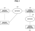
- the overall configuration includes at least one imaging apparatus 101, an image management apparatus 102, and an image analysis apparatus 103.
- the components are connected via a network 104.
- the imaging apparatus 101 is an information processing apparatus, such as a camera, a mobile phone, a smartphone, or a tablet.
- the image management apparatus 102 manages an image transferred from the imaging apparatus 101.
- the image analysis apparatus 103 When a processing request is made for image analysis on an image managed by the image management apparatus 102, the image analysis apparatus 103 accepts the processing request for image analysis and executes an image analysis process. After completion of the image analysis process, the image analysis apparatus 103 returns a result of the analysis to the image management apparatus 102.
- FIG. 2 A hardware configuration of the image management apparatus 102 according to the present embodiment will be described with reference to Fig. 2 .
- the image management apparatus 102 includes at least a central processing unit (CPU) 201, a random access memory (RAM) 202, a read only memory (ROM) 203, a network interface 204, an external storage device 205, a display device 206, and an input device 207.
- CPU central processing unit
- RAM random access memory
- ROM read only memory
- the CPU 201 controls the operations of the units constituting the image management apparatus 102 and serves as the main component that executes various processes (described below) as processes to be performed by the image management apparatus 102.
- the RAM 202 is a memory that temporarily stores data and control information, and serves as a work area to be used by the CPU 201 when various processes are executed.
- the ROM 203 stores fixed operation setting values, operation programs, and any other similar data of the image management apparatus 102.
- the network interface 204 provides a function for connecting to a network to perform communication.
- the network interface 204 allows the image management apparatus 102 to transmit and receive data to and from an external apparatus.
- the external storage device 205 is a device for storing data, and has an interface for receiving input/output (I/O) commands for reading and writing data.
- the external storage device 205 may be, for example, a hard disk drive (HDD), a solid state drive (SSD), an optical disk drive, a semiconductor storage device, or another type of a storage device.
- the external storage device 205 stores computer programs and data for causing the CPU 201 to execute processes (described below) as process to be performed by the image management apparatus 102.
- the display device 206 is a liquid crystal display (LCD), for example, and displays various information to the user.
- LCD liquid crystal display
- the input device 207 is a keyboard, a mouse or a touch panel, for example, and receives an input from the user.
- a configuration of the image management apparatus 102 according to the present embodiment will be described with reference to Fig. 3 .
- the image management apparatus 102 in the present embodiment has an image management unit 301, a transmission unit 302, a reception unit 303, a result code determination unit 304, a subsequent process determination unit 305, a retry control unit 306, an analysis image information management unit 307, a job management unit 308, and an analysis result management unit 309.
- the image management unit 301 stores images.
- the images transferred from the imaging apparatus 101 are managed by the image management unit 301.
- the transmission unit 302 transmits, to the image analysis apparatus 103, a processing request for analyzing an image managed by the image management unit 301.
- the reception unit 303 receives a result of an image analysis process from the image management apparatus 102.
- the result code determination unit 304 determines whether the process has ended normally or abnormally by referring to a result code included in the result of the image analysis process received by the reception unit 303. If the process has ended abnormally, the result code determination unit 304 further determines a cause category.
- the subsequent process determination unit 305 determines a subsequent process based on the result of the determination by the result code determination unit 304.
- the retry control unit 306 in the subsequent process determination unit 305 determines whether to make a retry, depending on the cause category.
- the retry control unit 306 also determines whether the upper limit of retries set in the system has been reached.
- the analysis image information management unit 307 manages information on an image to be analyzed when an image analysis request is made to the image analysis apparatus 103.
- the job management unit 308 manages an association between an image to be analyzed and an analysis process to be executed when an image analysis request is made to the image analysis apparatus 103.
- an analysis process to be executed on one image is called a "job”, and a job identification (ID) that uniquely identifies the job is assigned each time an analysis process is executed.
- ID job identification
- the analysis result management unit 309 manages analysis results received from the image analysis apparatus 103.
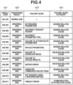
- a result code is an identification code, such as A01-002, and is associated with a cause of failure and a category of a cause of failure.
- a result code 401 is included in the analysis result received from the image analysis apparatus 103.
- Processing result 402 indicates a result of an image analysis process and takes the value of either "normal end” or "abnormal end”.
- a failure cause 403 indicates a failure cause in the image analysis process and also indicates the content of the failure cause. If the processing result indicates "normal end", this item has no value.
- a failure cause category 404 indicates a cause category for classifying failure causes and takes one of the values "sender-related cause,” “receiver-related cause”, and "communication path-related cause”.
- the sender-related cause among the failure cause categories indicates a cause of a failure resulting from the sender side, and sender-related failure causes include "no required parameters”, “incorrect (invalid) request header”, “not valid parameters”, and "not a request using a specified method”.
- the communication path-related cause among the failure cause categories indicates a cause of a failure resulting from a communication path, and communication path-related failure causes include "timeout error".
- receiver-related cause among the failure cause categories indicates a cause of a failure resulting from the receiver side
- receiver-related failure causes include "failure to download image”, “image in an unsupported format”, and "corrupted image”, "server error”.
- Figs. 5A and 5B illustrate a flowchart with a series of steps from when an image is transferred from the imaging apparatus 101 to the image management apparatus 102 to when the image analysis apparatus 103 executes an analysis process and the image management apparatus 102 stores a result of the analysis.
- step S501 an image captured by the imaging apparatus 101 is transferred to the image management apparatus 102.
- the process in this step causes the image to be stored in the image management unit 301.
- the image is assigned an image ID that uniquely identifies the image.
- the storage of the image starts an image analysis process.
- step S502 information on the image to be analyzed is written in the analysis image information management unit 307.
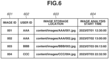
- Fig. 6 illustrates an example of the information stored in the analysis image information management unit 307.
- the information stored includes an image ID 601 of the to be analyzed, a user ID 602 that is an identifier of a user who is the owner of the image, an image storage location 603 that indicates the storage location of the image, and an image analysis start time 604 that is a time when the image analysis is started.
- the image storage location 603 is, for example, a path on a cloud storage or a path to a storage area in the image management apparatus 102.
- the image analysis start time 604 is a time when the information is written in the analysis image information management unit 307.
- a signed uniform resource location (URL) of the image to be analyzed is issued.
- the signed URL of the image is transmitted to the image analysis apparatus 103 as a request parameter for an image analysis request.
- the image analysis apparatus 103 accesses the URL to download the image.
- the method of transferring the image is not limited to the above method.
- Image data may be directly transmitted to the image analysis apparatus 103, or the image may be placed in a storage area accessible by the image analysis apparatus 103.
- step S504 the image analysis apparatus 103 is requested to perform an analysis process.
- the request includes the signed URL issued in step S503 and a notification destination (end point) that receives a result of the analysis, as request parameters.
- the image analysis apparatus 103 makes two types of responses: a synchronous response and an asynchronous response that returns a result of analysis after an analysis process is completed.
- Each response includes a job ID and a result code.
- Figs. 7A to 7D illustrate examples of response information from the image analysis apparatus 103.
- Figs. 7A to 7D illustrate examples of synchronous responses of "normal end" and "abnormal end” and asynchronous responses of "normal end” and "abnormal end", respectively.
- step S505 a synchronous response is received from the image analysis apparatus 103. Then, in step S506, the result code included in the response is determined. In steps S507 and S508, the result codes in Fig. 4 are referenced to determine whether the image analysis process has been successful (normal end) or has failed (abnormal end). If the image analysis process has failed, a subsequent process is determined based on the failure cause category 404. If the failure cause category is a sender-related cause (YES in step S507), the process proceeds to step S509. If the failure cause category is not a sender-related cause (NO in step S507), the process proceeds to step S508.
- step S508 If the failure cause category is a receiver-related cause or a communication path-related cause (YES in step S508), the process proceeds to step S510. If the failure cause category is not a receiver-related cause or a communication path-related cause (NO in step S508), the process proceeds to step S513.
- the image stored in the image management apparatus 102 is temporarily copied to another area in the image management apparatus 102.
- the image to be investigated may no longer exist e.g. due to deletion of the image from the image management apparatus 102 by a user, user's withdrawal from membership.
- the process content of step S509 and the process content of step S510 may be different. For example, in step S509, a notification of occurrence of an error may be made to an administrator of the image management apparatus 102.
- step S510 a retry process is performed.
- the upper limit of the number of retires (retry count) of an analysis process on each image is set to three. If the analysis process fails after three retries, the analysis process is determined to have "failed”.
- step S511 the number of retires is incremented by one, and in step S512, it is determined whether the number of retires has exceeded the upper limit of three. If it is determined in step S512 that the upper limit has not been exceeded (NO in step S512), the processing returns to step S504. In step S504, an image analysis request is transmitted to the image analysis apparatus 103 again.
- step S513 the image and job-related information are written to the job management unit 308.
- Fig. 8 illustrates an example of the information to be stored in the job management unit 308.
- the information includes a processing count 803 that indicates the number of times an analysis process has been performed with a combination of job ID 801 and image ID 802.
- the initial value of the processing count 803 is "1", and the processing count is incremented each time a retry process is performed. When the retry is made three times that is the upper limit, the processing count becomes "4".
- step S504 the image analysis apparatus 103 accesses the received signed URL, downloads the image, and starts an analysis process. Upon completion of the analysis process, the image analysis apparatus 103 transmits a result of the analysis process as an asynchronous response to the result notification destination.
- step S514 the image management apparatus 102 receives the asynchronous response from the image analysis apparatus 103.
- step S515 the job ID included in the received asynchronous response is read from the job management unit 308 to acquire the image information and the number of retries.
- step S516 the result code included in the asynchronous response is determined.
- steps S507 and S508 in steps S517 and S518, the result codes in Fig. 4 are referenced to determine whether the image analysis process has been successful (normal end) or has failed (abnormal end).
- step S519 the analysis result is stored in the analysis result management unit 309.
- the received analysis result includes information illustrated in Fig. 7C .
- the above is the flow of the series of processing steps from the transfer of the image from the imaging apparatus 101 to the image management apparatus 102, to the execution of the analysis process by the image analysis apparatus 103 and the storage of the analysis result by the image management apparatus 102.
- a request for one analysis process is made to the image analysis apparatus 103.
- a plurality of calls may be made in a multi-stage manner.
- a result code is issued in the same manner for each of results of a first analysis process (for example, an object analysis process) and a second analysis process (for example, a face recognition process), and a subsequent process is determined.
- the failure cause category is determined based on the result code received together with the result of the image analysis, and the subsequent process is determined. This makes it possible to, in analyzing an image, reduce failures in the analysis process without unnecessary retries.
- Embodiment(s) of the present invention can also be realized by a computer of a system or apparatus that reads out and executes computer executable instructions (e.g., one or more programs) recorded on a storage medium (which may also be referred to more fully as a 'non-transitory computer-readable storage medium') to perform the functions of one or more of the above-described embodiment(s) and/or that includes one or more circuits (e.g., application specific integrated circuit (ASIC)) for performing the functions of one or more of the above-described embodiment(s), and by a method performed by the computer of the system or apparatus by, for example, reading out and executing the computer executable instructions from the storage medium to perform the functions of one or more of the above-described embodiment(s) and/or controlling the one or more circuits to perform the functions of one or more of the above-described embodiment(s).
- computer executable instructions e.g., one or more programs
- a storage medium which may also be referred to more fully as
- the computer may comprise one or more processors (e.g., central processing unit (CPU), micro processing unit (MPU)) and may include a network of separate computers or separate processors to read out and execute the computer executable instructions.
- the computer executable instructions may be provided to the computer, for example, from a network or the storage medium.
- the storage medium may include, for example, one or more of a hard disk, a random-access memory (RAM), a read only memory (ROM), a storage of distributed computing systems, an optical disk (such as a compact disc (CD), digital versatile disc (DVD), or Blu-ray Disc (BD) TM ), a flash memory device, and a memory card.
Landscapes
- Engineering & Computer Science (AREA)
- Theoretical Computer Science (AREA)
- Multimedia (AREA)
- Signal Processing (AREA)
- General Engineering & Computer Science (AREA)
- Human Computer Interaction (AREA)
- Physics & Mathematics (AREA)
- General Physics & Mathematics (AREA)
- Computing Systems (AREA)
- Facsimiles In General (AREA)
- Debugging And Monitoring (AREA)
Abstract
Description
- The present invention relates to an image management apparatus that manages images transferred from an imaging apparatus, an image analysis apparatus that analyzes images, a determination and control method for determining a subsequent process based on a result of an analysis process, and a computer program.
- As a development method of software systems, there is a development method called "microservice architecture" by which the functions of an application are divided into small "services" and the services are collaborated to operate the system. The services operated by respective independent processes collaborate through remote communication using a lightweight mechanism such as RESTful Application Programming Interface (API). For example, even if a failure occurs in a certain service, the effect of the failure can be suppressed locally, which brings about an advantage that the fault tolerance of the entire application is improved.
- In recent years, applications that adopt this microservice architecture have increasingly become popular. For example, in image management services that manage images, there is an application configured such that its functions, such as an image analysis function and an image transfer function of transferring images to external storage or social networking service (SNS), are provided independently as separate services.
- In an application configured with a microservice architecture as described above, a service communicates with another service via, for example, a RESTful API to make a call. A call between services may fail for various reasons, such as a setting error on the caller side, a network error, or a failure in the called service. If a call to a service fails, the functions of the application cannot be provided, causing inconvenience to users. For this reason, it is desirable to prevent a failure of a call between services as much as possible.
-
Japanese Patent Application Laid-Open No. 2022-109916 - However, according to the technique discussed in
Japanese Patent Application Laid-Open No. 2022-109916 - The present invention has been made in view of the above-described problems and is directed to reducing failures in retrying an analysis request in an image management apparatus that communicates with an image analysis apparatus.
- According to a first aspect of the present invention, there is provided an image management apparatus as specified in
claims 1 to 11. According to a second aspect of the present invention, there is provided a method as specified in claim 12. According to a third aspect of the present invention, there is provided a computer program as specified in claim 13. - Further features of the present invention will become apparent from the following description of embodiments with reference to the attached drawings.
-
-
Fig. 1 is a diagram illustrating an overall configuration. -
Fig. 2 is a diagram illustrating a hardware configuration of an image management apparatus. -
Fig. 3 is a diagram illustrating a functional configuration of the image management apparatus. -
Fig. 4 is a diagram illustrating an example of result codes and information associated with the result codes. -
Figs. 5A and5B are a flowchart illustrating a process flow from an image transfer process to a process of saving analysis results. -
Fig. 6 is a diagram illustrating an example of information stored in an analysis image management unit. -
Figs. 7A to 7D illustrate examples of response information from the image analysis apparatus. -
Fig. 8 is a diagram illustrating an example of information stored in a job management unit. - Hereinafter, an embodiment will be described in detail with reference to the accompanying drawings. The configuration described in the following embodiment is merely an example, and the present invention is not limited to the configuration illustrated in the drawings.
- In the present embodiment described below, an example is described in which an image management apparatus that manages an image uploaded from an imaging apparatus communicates with an image analysis apparatus that performs an analysis process on the image and determines a subsequent process based on a result code received along with a result of the analysis process.
- An overall configuration according to the present embodiment will be described with reference to
Fig. 1 . - As illustrated in
Fig. 1 , the overall configuration includes at least oneimaging apparatus 101, animage management apparatus 102, and animage analysis apparatus 103. The components are connected via anetwork 104. - The
imaging apparatus 101 is an information processing apparatus, such as a camera, a mobile phone, a smartphone, or a tablet. - The
image management apparatus 102 manages an image transferred from theimaging apparatus 101. - When a processing request is made for image analysis on an image managed by the
image management apparatus 102, theimage analysis apparatus 103 accepts the processing request for image analysis and executes an image analysis process. After completion of the image analysis process, theimage analysis apparatus 103 returns a result of the analysis to theimage management apparatus 102. - The above is the overall configuration of the present embodiment.
- A hardware configuration of the
image management apparatus 102 according to the present embodiment will be described with reference toFig. 2 . - As illustrated in
Fig. 2 , theimage management apparatus 102 includes at least a central processing unit (CPU) 201, a random access memory (RAM) 202, a read only memory (ROM) 203, anetwork interface 204, anexternal storage device 205, adisplay device 206, and aninput device 207. - The
CPU 201 controls the operations of the units constituting theimage management apparatus 102 and serves as the main component that executes various processes (described below) as processes to be performed by theimage management apparatus 102. - The
RAM 202 is a memory that temporarily stores data and control information, and serves as a work area to be used by theCPU 201 when various processes are executed. - The
ROM 203 stores fixed operation setting values, operation programs, and any other similar data of theimage management apparatus 102. - The
network interface 204 provides a function for connecting to a network to perform communication. Thenetwork interface 204 allows theimage management apparatus 102 to transmit and receive data to and from an external apparatus. - The
external storage device 205 is a device for storing data, and has an interface for receiving input/output (I/O) commands for reading and writing data. Theexternal storage device 205 may be, for example, a hard disk drive (HDD), a solid state drive (SSD), an optical disk drive, a semiconductor storage device, or another type of a storage device. Theexternal storage device 205 stores computer programs and data for causing theCPU 201 to execute processes (described below) as process to be performed by theimage management apparatus 102. - The
display device 206 is a liquid crystal display (LCD), for example, and displays various information to the user. - The
input device 207 is a keyboard, a mouse or a touch panel, for example, and receives an input from the user. - A configuration of the
image management apparatus 102 according to the present embodiment will be described with reference toFig. 3 . - The
image management apparatus 102 in the present embodiment has animage management unit 301, atransmission unit 302, areception unit 303, a resultcode determination unit 304, a subsequentprocess determination unit 305, aretry control unit 306, an analysis imageinformation management unit 307, ajob management unit 308, and an analysisresult management unit 309. - The
image management unit 301 stores images. The images transferred from theimaging apparatus 101 are managed by theimage management unit 301. - The
transmission unit 302 transmits, to theimage analysis apparatus 103, a processing request for analyzing an image managed by theimage management unit 301. - The
reception unit 303 receives a result of an image analysis process from theimage management apparatus 102. - The result
code determination unit 304 determines whether the process has ended normally or abnormally by referring to a result code included in the result of the image analysis process received by thereception unit 303. If the process has ended abnormally, the resultcode determination unit 304 further determines a cause category. - The subsequent
process determination unit 305 determines a subsequent process based on the result of the determination by the resultcode determination unit 304. - The retry
control unit 306 in the subsequentprocess determination unit 305 determines whether to make a retry, depending on the cause category. The retrycontrol unit 306 also determines whether the upper limit of retries set in the system has been reached. - The analysis image
information management unit 307 manages information on an image to be analyzed when an image analysis request is made to theimage analysis apparatus 103. - The
job management unit 308 manages an association between an image to be analyzed and an analysis process to be executed when an image analysis request is made to theimage analysis apparatus 103. In the present embodiment, an analysis process to be executed on one image is called a "job", and a job identification (ID) that uniquely identifies the job is assigned each time an analysis process is executed. - The analysis
result management unit 309 manages analysis results received from theimage analysis apparatus 103. - Next, result codes and information associated with the result codes in the present embodiment will be described with reference to
Fig. 4 . A result code is an identification code, such as A01-002, and is associated with a cause of failure and a category of a cause of failure. - A
result code 401 is included in the analysis result received from theimage analysis apparatus 103. -
Processing result 402 indicates a result of an image analysis process and takes the value of either "normal end" or "abnormal end". - A
failure cause 403 indicates a failure cause in the image analysis process and also indicates the content of the failure cause. If the processing result indicates "normal end", this item has no value. - A
failure cause category 404 indicates a cause category for classifying failure causes and takes one of the values "sender-related cause," "receiver-related cause", and "communication path-related cause". - The sender-related cause among the failure cause categories indicates a cause of a failure resulting from the sender side, and sender-related failure causes include "no required parameters", "incorrect (invalid) request header", "not valid parameters", and "not a request using a specified method".
- The communication path-related cause among the failure cause categories indicates a cause of a failure resulting from a communication path, and communication path-related failure causes include "timeout error".
- The receiver-related cause among the failure cause categories indicates a cause of a failure resulting from the receiver side, and receiver-related failure causes include "failure to download image", "image in an unsupported format", and "corrupted image", "server error".
- In the present embodiment, a series of processing steps from when an image is transferred from the
imaging apparatus 101 to theimage management apparatus 102 to when theimage analysis apparatus 103 executes an analysis process and theimage management apparatus 102 stores a result of the analysis will be described. -
Figs. 5A and5B illustrate a flowchart with a series of steps from when an image is transferred from theimaging apparatus 101 to theimage management apparatus 102 to when theimage analysis apparatus 103 executes an analysis process and theimage management apparatus 102 stores a result of the analysis. - In step S501, an image captured by the
imaging apparatus 101 is transferred to theimage management apparatus 102. The process in this step causes the image to be stored in theimage management unit 301. When the image is stored in theimage management apparatus 102, the image is assigned an image ID that uniquely identifies the image. The storage of the image starts an image analysis process. In step S502, information on the image to be analyzed is written in the analysis imageinformation management unit 307.Fig. 6 illustrates an example of the information stored in the analysis imageinformation management unit 307. - The information stored includes an
image ID 601 of the to be analyzed, auser ID 602 that is an identifier of a user who is the owner of the image, animage storage location 603 that indicates the storage location of the image, and an imageanalysis start time 604 that is a time when the image analysis is started. Theimage storage location 603 is, for example, a path on a cloud storage or a path to a storage area in theimage management apparatus 102. The imageanalysis start time 604 is a time when the information is written in the analysis imageinformation management unit 307. - Next, in step S503, a signed uniform resource location (URL) of the image to be analyzed is issued. In the present embodiment, the signed URL of the image is transmitted to the
image analysis apparatus 103 as a request parameter for an image analysis request. Theimage analysis apparatus 103 accesses the URL to download the image. The method of transferring the image is not limited to the above method. Image data may be directly transmitted to theimage analysis apparatus 103, or the image may be placed in a storage area accessible by theimage analysis apparatus 103. - In step S504, the
image analysis apparatus 103 is requested to perform an analysis process. The request includes the signed URL issued in step S503 and a notification destination (end point) that receives a result of the analysis, as request parameters. In the present embodiment, when an analysis process request is made to theimage analysis apparatus 103, theimage analysis apparatus 103 makes two types of responses: a synchronous response and an asynchronous response that returns a result of analysis after an analysis process is completed. Each response includes a job ID and a result code.Figs. 7A to 7D illustrate examples of response information from theimage analysis apparatus 103.Figs. 7A to 7D illustrate examples of synchronous responses of "normal end" and "abnormal end" and asynchronous responses of "normal end" and "abnormal end", respectively. - In step S505, a synchronous response is received from the
image analysis apparatus 103. Then, in step S506, the result code included in the response is determined. In steps S507 and S508, the result codes inFig. 4 are referenced to determine whether the image analysis process has been successful (normal end) or has failed (abnormal end). If the image analysis process has failed, a subsequent process is determined based on thefailure cause category 404. If the failure cause category is a sender-related cause (YES in step S507), the process proceeds to step S509. If the failure cause category is not a sender-related cause (NO in step S507), the process proceeds to step S508. If the failure cause category is a receiver-related cause or a communication path-related cause (YES in step S508), the process proceeds to step S510. If the failure cause category is not a receiver-related cause or a communication path-related cause (NO in step S508), the process proceeds to step S513. - In the present embodiment, in steps S509 and S510, the image stored in the
image management apparatus 102 is temporarily copied to another area in theimage management apparatus 102. In investigating an image for which an image analysis process has failed, there is a possibility that the image to be investigated may no longer exist e.g. due to deletion of the image from theimage management apparatus 102 by a user, user's withdrawal from membership. In order to enable the investigation of the image for which the analysis has failed even in such a case, if an error occurs in the image analysis process, the image is temporarily copied to another area. At this time, the process content of step S509 and the process content of step S510 may be different. For example, in step S509, a notification of occurrence of an error may be made to an administrator of theimage management apparatus 102. - After step S510, a retry process is performed. In the present embodiment, the upper limit of the number of retires (retry count) of an analysis process on each image is set to three. If the analysis process fails after three retries, the analysis process is determined to have "failed". In step S511, the number of retires is incremented by one, and in step S512, it is determined whether the number of retires has exceeded the upper limit of three. If it is determined in step S512 that the upper limit has not been exceeded (NO in step S512), the processing returns to step S504. In step S504, an image analysis request is transmitted to the
image analysis apparatus 103 again. - If the analysis process is determined to have been "successful" based on the result code of the synchronization response, then in step S513, the image and job-related information are written to the
job management unit 308.Fig. 8 illustrates an example of the information to be stored in thejob management unit 308. - The information includes a
processing count 803 that indicates the number of times an analysis process has been performed with a combination ofjob ID 801 andimage ID 802. The initial value of theprocessing count 803 is "1", and the processing count is incremented each time a retry process is performed. When the retry is made three times that is the upper limit, the processing count becomes "4". - After an analysis process request is made in step S504, the
image analysis apparatus 103 accesses the received signed URL, downloads the image, and starts an analysis process. Upon completion of the analysis process, theimage analysis apparatus 103 transmits a result of the analysis process as an asynchronous response to the result notification destination. In step S514, theimage management apparatus 102 receives the asynchronous response from theimage analysis apparatus 103. In step S515, the job ID included in the received asynchronous response is read from thejob management unit 308 to acquire the image information and the number of retries. In step S516, the result code included in the asynchronous response is determined. As in steps S507 and S508, in steps S517 and S518, the result codes inFig. 4 are referenced to determine whether the image analysis process has been successful (normal end) or has failed (abnormal end). - If the result code in the asynchronous response is "normal end" and the analysis process has been "successful" (NO in steps S517 and S518), then in step S519, the analysis result is stored in the analysis
result management unit 309. The received analysis result includes information illustrated inFig. 7C . - In the present embodiment, the number of retries (retry count) per image is controlled in the series of steps in the analysis process (steps S504 to S518). For example, it is assumed that an analysis process of an image with image ID of "002" (image ID = 002) is started. If the analysis result is determined as "failed" based on the result code in the synchronous response in step S508 and a retry is performed, the number of retires becomes "1" in step S511. If the analysis result is determined as "successful" based on the result code in the synchronous response after steps S504 to S508 (NO in step S508), the process proceeds to step S513. In step S513, the processing count "2" is written to the job management unit 308 (job ID = J003 in
Fig. 8 ). If the analysis result is determined as "failed" based on the result code in the asynchronous response in step S518 and a retry is performed again, the number of reties becomes "2" in step S511. If the analysis result is determined as "successful" based on the result code in the synchronous response again, then in step S513, the process count "3" is written to the job management unit 308 (job ID = J004 inFig. 8 ). Similarly, if the analysis result is determined as "failed" based on the result code in the asynchronous response again in step S518 and a retry is performed again, the number of retries becomes "3" in step S511. If the analysis result is determined as "successful" based on the result code in the synchronous response again, in step S513, the process count "4" is written to the job management unit 308 (job ID = J005 inFig. 8 ). Finally, if the analysis result is determined as "failed" based on the result code in the asynchronous response again in step S518, the number of retries becomes "4" in step S511. In step S512, if it is determined that the number of retires exceeds the upper limit (YES in step S512), and the analysis process is determined to have "failed". - The above is the flow of the series of processing steps from the transfer of the image from the
imaging apparatus 101 to theimage management apparatus 102, to the execution of the analysis process by theimage analysis apparatus 103 and the storage of the analysis result by theimage management apparatus 102. - In the present embodiment, an example in which a request for one analysis process is made to the
image analysis apparatus 103. Alternatively, a plurality of calls may be made in a multi-stage manner. In this case, a result code is issued in the same manner for each of results of a first analysis process (for example, an object analysis process) and a second analysis process (for example, a face recognition process), and a subsequent process is determined. - In this manner, in the
image management apparatus 102 and theimage analysis apparatus 103 according to the present embodiment, the failure cause category is determined based on the result code received together with the result of the image analysis, and the subsequent process is determined. This makes it possible to, in analyzing an image, reduce failures in the analysis process without unnecessary retries. - Embodiment(s) of the present invention can also be realized by a computer of a system or apparatus that reads out and executes computer executable instructions (e.g., one or more programs) recorded on a storage medium (which may also be referred to more fully as a 'non-transitory computer-readable storage medium') to perform the functions of one or more of the above-described embodiment(s) and/or that includes one or more circuits (e.g., application specific integrated circuit (ASIC)) for performing the functions of one or more of the above-described embodiment(s), and by a method performed by the computer of the system or apparatus by, for example, reading out and executing the computer executable instructions from the storage medium to perform the functions of one or more of the above-described embodiment(s) and/or controlling the one or more circuits to perform the functions of one or more of the above-described embodiment(s). The computer may comprise one or more processors (e.g., central processing unit (CPU), micro processing unit (MPU)) and may include a network of separate computers or separate processors to read out and execute the computer executable instructions. The computer executable instructions may be provided to the computer, for example, from a network or the storage medium. The storage medium may include, for example, one or more of a hard disk, a random-access memory (RAM), a read only memory (ROM), a storage of distributed computing systems, an optical disk (such as a compact disc (CD), digital versatile disc (DVD), or Blu-ray Disc (BD)™), a flash memory device, and a memory card.
- According to the present invention, it is possible to reduce failures in retrying an analysis request in an image management apparatus that communicates with an image analysis apparatus.
- While the present invention has been described with reference to embodiments, it is to be understood that the invention is not limited to the disclosed embodiments.
Claims (13)
- An image management apparatus for managing an image, comprising:transmission means for transmitting an image analysis request to an image analysis apparatus for analyzing the image;reception means for receiving an analysis result, including a result code, from the image analysis apparatus;processing result determination means for determining a processing result based on the result code; andsubsequent process determination means for determining a subsequent process related to analysis of the image based on the processing result.
- The image management apparatus according to claim 1, wherein in a case where the processing result determination means determines that the analysis of the image has failed, the processing result determination means classifies, based on the result code, a failure of the analysis of the image into one of a failure resulting from a sender side of the image analysis request, a failure resulting from a communication path, and a failure resulting from a receiver side of the image analysis request.
- The image management apparatus according to claim 1, wherein the subsequent process determination means includes a retry control means for determining whether to retry the image analysis request.
- The image management apparatus according to claim 3, wherein the retry control means is arranged to retry the image analysis request in at least one of a case where a failure of the analysis of the image is classified as a failure resulting from a communication path and a case where a failure of the analysis of the image is a failure resulting from a receiver side of the image analysis request.
- The image management apparatus according to claim 3, wherein the retry control means does not retry the image analysis request in a case where a failure of the analysis of the image is classified as a failure resulting from a sender side of the image analysis request.
- The image management apparatus according to claim 3, wherein in a case where the retry control means determines not to retry the image analysis request, the subsequent process determination means is arranged to determine, as the subsequent process, o make a notification to an administrator.
- The image management apparatus according to claim 2, wherein the failure resulting from the sender side of the image analysis request is at least one of no required parameter, an invalid request header, an invalid parameter type, not a valid parameter, and a request not using a specified method.
- The image management apparatus according to claim 2, wherein the failure resulting from the communication path is a timeout error.
- The image management apparatus according to claim 2, wherein the failure resulting from the receiver side of the image analysis request is at least one of a failure to download an image, a failure to upload a result, an image in an unsupported format, an image corrupted, and a server error.
- The image management apparatus according to claim 1, wherein the result code is an identification code of A01-002 and is associated with a failure cause or a failure cause category.
- The image management apparatus according to claim 1, wherein the subsequent process determination means is arranged to determine, as the subsequent process, to copy the image in a case where the processing result determination means determines that the analysis of the image has failed.
- A method of controlling an image management apparatus for managing an image, the method comprising:transmitting an image analysis request to an image analysis apparatus for analyzing an image;receiving an analysis result, including a result code, from the image analysis apparatus;determining a processing result based on the result; anddetermining a subsequent process related to analysis of the image based on the processing result.
- A computer program for causing a computer to execute a method of controlling an image management apparatus according to claim 12.
Applications Claiming Priority (1)
| Application Number | Priority Date | Filing Date | Title |
|---|---|---|---|
| JP2023142031A JP7767367B2 (en) | 2023-09-01 | 2023-09-01 | Image management device, image management device control method, and computer program |
Publications (1)
| Publication Number | Publication Date |
|---|---|
| EP4518303A1 true EP4518303A1 (en) | 2025-03-05 |
Family
ID=92494618
Family Applications (1)
| Application Number | Title | Priority Date | Filing Date |
|---|---|---|---|
| EP24195416.3A Pending EP4518303A1 (en) | 2023-09-01 | 2024-08-20 | Image management apparatus, method of controlling image management apparatus, and computer program |
Country Status (5)
| Country | Link |
|---|---|
| US (1) | US20250080679A1 (en) |
| EP (1) | EP4518303A1 (en) |
| JP (1) | JP7767367B2 (en) |
| KR (1) | KR20250033947A (en) |
| CN (1) | CN119562010A (en) |
Citations (3)
| Publication number | Priority date | Publication date | Assignee | Title |
|---|---|---|---|---|
| JP2010225082A (en) * | 2009-03-25 | 2010-10-07 | Noritsu Koki Co Ltd | Image data management system and image data management method |
| US20210303895A1 (en) * | 2020-03-31 | 2021-09-30 | Canon Kabushiki Kaisha | Information processing apparatus for obtaining character string |
| JP2022109916A (en) | 2017-08-31 | 2022-07-28 | ブラザー工業株式会社 | Program and printing system |
Family Cites Families (7)
| Publication number | Priority date | Publication date | Assignee | Title |
|---|---|---|---|---|
| JPH10228365A (en) * | 1997-02-14 | 1998-08-25 | Canon Inc | Printing apparatus, printing system, and printing method |
| JP2002196916A (en) * | 2000-12-25 | 2002-07-12 | Ricoh Co Ltd | Printing system |
| DE60130341T2 (en) * | 2001-10-25 | 2009-04-16 | Hewlett-Packard Development Co., L.P., Houston | Remote network printing |
| JP2008293282A (en) * | 2007-05-24 | 2008-12-04 | Fuji Xerox Co Ltd | Data processing apparatus, data processing program, and data processing system |
| JP2011011427A (en) * | 2009-07-01 | 2011-01-20 | Oki Data Corp | Electronic device and electronic system |
| US9098226B2 (en) * | 2012-08-14 | 2015-08-04 | Seiko Epson Corporation | ePOS printing over a network |
| JP6214581B2 (en) * | 2015-01-30 | 2017-10-18 | キヤノン株式会社 | Document analysis system, document analysis apparatus, document analysis method, and program |
-
2023
- 2023-09-01 JP JP2023142031A patent/JP7767367B2/en active Active
-
2024
- 2024-08-20 EP EP24195416.3A patent/EP4518303A1/en active Pending
- 2024-08-22 KR KR1020240112555A patent/KR20250033947A/en active Pending
- 2024-08-27 US US18/816,664 patent/US20250080679A1/en active Pending
- 2024-08-29 CN CN202411194707.0A patent/CN119562010A/en active Pending
Patent Citations (3)
| Publication number | Priority date | Publication date | Assignee | Title |
|---|---|---|---|---|
| JP2010225082A (en) * | 2009-03-25 | 2010-10-07 | Noritsu Koki Co Ltd | Image data management system and image data management method |
| JP2022109916A (en) | 2017-08-31 | 2022-07-28 | ブラザー工業株式会社 | Program and printing system |
| US20210303895A1 (en) * | 2020-03-31 | 2021-09-30 | Canon Kabushiki Kaisha | Information processing apparatus for obtaining character string |
Also Published As
| Publication number | Publication date |
|---|---|
| KR20250033947A (en) | 2025-03-10 |
| JP2025035166A (en) | 2025-03-13 |
| CN119562010A (en) | 2025-03-04 |
| US20250080679A1 (en) | 2025-03-06 |
| JP7767367B2 (en) | 2025-11-11 |
Similar Documents
| Publication | Publication Date | Title |
|---|---|---|
| US10694057B2 (en) | Apparatus, method and storage medium that stores program | |
| US9720776B2 (en) | Server system, method for controlling the same, and program for executing parallel distributed processing | |
| US9658805B2 (en) | Information processing apparatus, system, storage medium, and information processing method for establishing communication path | |
| US11182118B2 (en) | Image forming apparatus, control method for the same, image forming system and storage medium | |
| US9917959B2 (en) | System, method and apparatus for managing job processing between a processing apparatus and server | |
| US20210132886A1 (en) | Printing system, server, and printing method | |
| US20170353432A1 (en) | Network device that registers event, method of controlling the same, and storage medium | |
| US20150046556A1 (en) | Information processing apparatus, method of controlling the same, non-transitory computer-readable storage medium, and information processing system | |
| US9838397B2 (en) | Information processing apparatus and control method thereof | |
| US10846033B2 (en) | Print server, control method, and storage medium | |
| US11695886B2 (en) | Information processing system, method and storage medium | |
| US20250080679A1 (en) | Image management apparatus, method of controlling image management apparatus, and storage medium | |
| US12541314B2 (en) | Information processing apparatus, and control method for managing log information that provides a storage function connected to a network | |
| EP4303712B1 (en) | Printing apparatus, control method, and program | |
| US12113940B2 (en) | Information processing apparatus, control method therefor, and storage medium | |
| US11442812B2 (en) | System and method | |
| US10834276B2 (en) | System, management server system and control method | |
| JP7119582B2 (en) | Information processing system and management server | |
| US10567341B2 (en) | Information processing apparatus capable of receiving event, method of controlling the same, and storage medium | |
| US12556807B2 (en) | Display control device, display control method, and storage medium | |
| US12177393B2 (en) | Document processing system and control method thereof | |
| JP2014170424A (en) | Information processing system, job management device, and program | |
| JP7435061B2 (en) | Information processing system, information processing device, equipment and information processing method |
Legal Events
| Date | Code | Title | Description |
|---|---|---|---|
| PUAI | Public reference made under article 153(3) epc to a published international application that has entered the european phase |
Free format text: ORIGINAL CODE: 0009012 |
|
| STAA | Information on the status of an ep patent application or granted ep patent |
Free format text: STATUS: THE APPLICATION HAS BEEN PUBLISHED |
|
| AK | Designated contracting states |
Kind code of ref document: A1 Designated state(s): AL AT BE BG CH CY CZ DE DK EE ES FI FR GB GR HR HU IE IS IT LI LT LU LV MC ME MK MT NL NO PL PT RO RS SE SI SK SM TR |
|
| STAA | Information on the status of an ep patent application or granted ep patent |
Free format text: STATUS: REQUEST FOR EXAMINATION WAS MADE |
|
| 17P | Request for examination filed |
Effective date: 20250905 |
|
| STAA | Information on the status of an ep patent application or granted ep patent |
Free format text: STATUS: EXAMINATION IS IN PROGRESS |
|
| 17Q | First examination report despatched |
Effective date: 20260130 |