EP4518221A1 - Verfahren zur übertragung eines gemeinsam genutzten physikalischen uplink-kanals sowie vorrichtung und speichermedium - Google Patents
Verfahren zur übertragung eines gemeinsam genutzten physikalischen uplink-kanals sowie vorrichtung und speichermedium Download PDFInfo
- Publication number
- EP4518221A1 EP4518221A1 EP23795101.7A EP23795101A EP4518221A1 EP 4518221 A1 EP4518221 A1 EP 4518221A1 EP 23795101 A EP23795101 A EP 23795101A EP 4518221 A1 EP4518221 A1 EP 4518221A1
- Authority
- EP
- European Patent Office
- Prior art keywords
- srs resource
- resource set
- configuration
- coreset
- index
- Prior art date
- Legal status (The legal status is an assumption and is not a legal conclusion. Google has not performed a legal analysis and makes no representation as to the accuracy of the status listed.)
- Pending
Links
Images


Classifications
-
- H—ELECTRICITY
- H04—ELECTRIC COMMUNICATION TECHNIQUE
- H04L—TRANSMISSION OF DIGITAL INFORMATION, e.g. TELEGRAPHIC COMMUNICATION
- H04L5/00—Arrangements affording multiple use of the transmission path
- H04L5/003—Arrangements for allocating sub-channels of the transmission path
- H04L5/0048—Allocation of pilot signals, i.e. of signals known to the receiver
- H04L5/0051—Allocation of pilot signals, i.e. of signals known to the receiver of dedicated pilots, i.e. pilots destined for a single user or terminal
-
- H—ELECTRICITY
- H04—ELECTRIC COMMUNICATION TECHNIQUE
- H04L—TRANSMISSION OF DIGITAL INFORMATION, e.g. TELEGRAPHIC COMMUNICATION
- H04L5/00—Arrangements affording multiple use of the transmission path
- H04L5/0091—Signalling for the administration of the divided path, e.g. signalling of configuration information
- H04L5/0094—Indication of how sub-channels of the path are allocated
-
- H—ELECTRICITY
- H04—ELECTRIC COMMUNICATION TECHNIQUE
- H04W—WIRELESS COMMUNICATION NETWORKS
- H04W72/00—Local resource management
- H04W72/04—Wireless resource allocation
- H04W72/115—Grant-free or autonomous transmission
-
- H—ELECTRICITY
- H04—ELECTRIC COMMUNICATION TECHNIQUE
- H04W—WIRELESS COMMUNICATION NETWORKS
- H04W72/00—Local resource management
- H04W72/12—Wireless traffic scheduling
- H04W72/1263—Mapping of traffic onto schedule, e.g. scheduled allocation or multiplexing of flows
- H04W72/1268—Mapping of traffic onto schedule, e.g. scheduled allocation or multiplexing of flows of uplink data flows
-
- H—ELECTRICITY
- H04—ELECTRIC COMMUNICATION TECHNIQUE
- H04L—TRANSMISSION OF DIGITAL INFORMATION, e.g. TELEGRAPHIC COMMUNICATION
- H04L5/00—Arrangements affording multiple use of the transmission path
- H04L5/003—Arrangements for allocating sub-channels of the transmission path
- H04L5/0044—Allocation of payload; Allocation of data channels, e.g. PDSCH or PUSCH
-
- H—ELECTRICITY
- H04—ELECTRIC COMMUNICATION TECHNIQUE
- H04L—TRANSMISSION OF DIGITAL INFORMATION, e.g. TELEGRAPHIC COMMUNICATION
- H04L5/00—Arrangements affording multiple use of the transmission path
- H04L5/003—Arrangements for allocating sub-channels of the transmission path
- H04L5/0053—Allocation of signalling, i.e. of overhead other than pilot signals
-
- H—ELECTRICITY
- H04—ELECTRIC COMMUNICATION TECHNIQUE
- H04W—WIRELESS COMMUNICATION NETWORKS
- H04W72/00—Local resource management
- H04W72/20—Control channels or signalling for resource management
- H04W72/23—Control channels or signalling for resource management in the downlink direction of a wireless link, i.e. towards a terminal
- H04W72/232—Control channels or signalling for resource management in the downlink direction of a wireless link, i.e. towards a terminal the control data signalling from the physical layer, e.g. DCI signalling
Definitions
- the present disclosure relates to the technical field of communications, in particular to a transmission method for a physical uplink shared channel, a device, and a storage medium.
- a sounding reference signal resource set includes a plurality of SRS resources.
- DCI downlink control information
- CG configured grant
- SRI sounding reference signal resource indicator
- Which SRS resource to use may be determined according to the SRI, and then a physical uplink shared channel (PUSCH) is transmitted to a network side based on the SRS resource.
- PUSCH physical uplink shared channel
- the PUSCH is scheduled independently by using a multi-downlink control information (DCI) framework, or the PUSCH is transmitted simultaneously through a plurality of CG configurations, or the PUSCH is scheduled through the DCI and the PUSCH is transmitted through the CG configuration simultaneously, if a plurality of SRS resource sets are configured, which SRS resource set the SRI in the DCI or the CG configuration acts on cannot be determined by a terminal. As a result, correct transmission of the PUSCH cannot be effectively ensured, and a transmission performance of the PUSCH is reduced.
- DCI multi-downlink control information
- the present disclosure provides a transmission method for a physical uplink shared channel, a device, and a storage medium, which may enable a terminal device to determine an SRS resource set indicated by an SRI in DCI or in a CG configuration, thereby ensuring correct transmission of the PUSCH is ensured, and improving a transmission performance of the PUSCH.
- the present disclosure provides a transmission method for a physical uplink shared channel, applied to a terminal device, comprising:
- the SRS resource set indicated by the SRI in the DCI or in the CG configuration is determined, thereby ensuring correct transmission of the PUSCH, and improving a transmission performance of the PUSCH.
- the specified parameter includes at least one of the following: a high-level parameter CORESETPoolIndex, a detected control resource set (CORESET) used to transmit the DCI or a physical downlink control channel (PDCCH), a transmission configuration indication (TCI) state configuration, a specified information field in the DCI, a capability value index of a terminal device, an SRS resource set index, a CG index, or a specified radio resource control (RRC) parameter.
- a high-level parameter CORESETPoolIndex a detected control resource set (CORESET) used to transmit the DCI or a physical downlink control channel (PDCCH), a transmission configuration indication (TCI) state configuration, a specified information field in the DCI, a capability value index of a terminal device, an SRS resource set index, a CG index, or a specified radio resource control (RRC) parameter.
- a correspondence with the adopted SRS resource set can be established through the indication information on a network side or the predefined rule by adopting corresponding parameters, which is more convenient to implement, and a capability to determine the SRS resource set may be realized by multiplexing the existing parameters.
- which SRS resource set is adopted to transmit the PUSCH can be indicated to the terminal device by configuring some parameters, and the configuration of these parameters is simpler to realize, which can facilitate the realization of the indication to the terminal device.
- the indication information includes at least one of the following:
- the specified information field in the DCI includes at least one of the following:
- which SRS resource set is adopted may be indicated to the terminal device through some information fields in the DCI, so that multiplexing of DCI information is realized.
- the indication information includes the CORESETPoolIndex configured in the high-level parameter of the SRS resource set, and determining the SRS resource set comprises:
- the adopted SRS resource may be determined based on the SRS resource set associated with the CORESET or the CORESETPoolIndex, and only the CORESET or the CORESETPoolIndex needs to be known during realization to determine the SRS resource, which is easy to realize.
- the SRS resource set may be determined from the high-level parameter of the SRS resource set, and a realization mode is simple.
- the indication information includes the capability value index of the terminal device configured for the CORESET, and determining the SRS resource set comprises:
- the SRS resource set may be determined based on the CORESET, and a realization mode is simple.
- the indication information of the network device includes the capability value index of the terminal device configured for the CORESET, and determining the SRS resource set comprises:
- the capability value index of the terminal device may be configured for the CORESET, then the SRS resource set is determined, and a realization mode is simple.
- the indication information includes the specified information field in the DCI, and determining the SRS resource set comprises:
- the SRS resource set may be determined based on the information field of the DCI, and a realization mode is simple.
- the indication information includes the specified information field in the DCI, and before obtaining the specified information field in the DCI, the method further comprises: transmitting capability information for supporting the specified information field in the DCI to the network device.
- each of the TRPs performs an indication of the SRS resource set or an indication of the capability value independently, which may lead to the indication of the same SRS resource set by a plurality of pieces of DCI.
- the indication information includes the TCI state configuration
- determining the SRS resource set comprises:
- the SRS resource set may be determined based on the TCI state configuration, and a realization mode is simple.
- the TCI state configuration associated with the DCI includes at least one of the following:
- the adopted SRS resource set may be determined by configuring different TCI state configurations, and a realization mode is simple.
- the SRS resource set associated with the TCI state configuration includes at least one of the following:
- the adopted SRS resource set may be determined by configuring different TCI state configurations, and a realization mode is simple.
- the specified parameter includes the detected CORESET used to transmit the DCI or the PDCCH, and determining the SRS resource set based on the association comprises:
- the association is determined based on the configured SRS resource set or based on the capability value index reported by the terminal device.
- the specified parameter includes the CORESET used to transmit the DCI or the physical downlink control channel (PDCCH)
- the association includes an association between the CORESET and the SRS resource set
- determining the association based on the configured SRS resource set comprises:
- the association includes a first relationship between the CORESET and the capability value index, and includes a second relationship between the capability value index and the SRS resource set, and determining the association based on a capability value reported by the terminal device comprises:
- selecting the SRS resource set associated with the CORESET or the CORESETPoolIndex of the CORESET from the at least one SRS resource set comprises:
- the indication information includes the CORESETPoolIndex configured in the high-level parameter of the SRS resource set, and determining the SRS resource set comprises:
- the indication information includes the SRS resource set index associated with the CG configuration or the SRI
- determining the SRS resource set comprises: determining an SRS resource set corresponding to the SRS resource set index associated with the CG configuration or the SRI for transmitting the PUSCH.
- the indication information includes the TCI state configuration
- determining the SRS resource set comprises:
- the association includes:
- the association between the CG index configured in the CG configuration and the SRS resource set includes: an odd CG index corresponds to one SRS resource set of two SRS resource sets configured by the network device, and an even CG index corresponds to the other SRS resource set.
- the SRS resource set is determined based on the CG index, and a realization mode is simple.
- the CG configuration includes a second CG index of another associated CG.
- the association between the specified RRC parameter configured in the CG configuration and the SRS resource set includes:
- the SRS resource set is determined based on the second CG index (the specified RRC parameter), and a realization mode is simple.
- the association between the specified RRC parameter configured in the CG configuration and the SRS resource set includes: a first RRC parameter configured in the CG configuration corresponds to one SRS resource set of two SRS resource sets configured by the network device, and a second RRC parameter corresponds to the other SRS resource set; wherein one or two of the first RRC parameter and the second RRC parameter are configured in the CG configuration.
- the SRS resource set is determined based on the specified RRC parameters (the first RRC parameter and the second RRC parameter), and a realization mode is simple.
- the CG configuration does not include information associated with other CGs, and the association includes: the CG configuration corresponds to one SRS resource set of a plurality of SRS resource sets configured by the network device.
- a transmission method for a physical uplink shared channel is provided and applied to a network device, and comprises:
- the specified parameter includes at least one of the following: a high-level parameter CORESETPoolIndex, a detected CORESET used to transmit DCI or a physical downlink control channel (PDCCH), a transmission configuration indication (TCI) state configuration, a specified information field in the DCI, a capability value index of the terminal device, an SRS resource set index, a configured grant (CG) index, or a specified radio resource control (RRC) parameter.
- a high-level parameter CORESETPoolIndex a detected CORESET used to transmit DCI or a physical downlink control channel (PDCCH)
- TCI transmission configuration indication
- TCI transmission configuration indication
- a specified information field in the DCI a capability value index of the terminal device
- SRS resource set index a configured grant index
- RRC radio resource control
- the indication information includes at least one of the following:
- the specified information field in the DCI includes at least one of the following:
- the method further comprises:
- the indication information includes a TCI state configuration
- configuring the indication information used to indicate the SRS resource set for the terminal device comprises:
- the method further comprises: configuring at least two physical uplink shared channel (PUSCH) transmission parameters for the terminal device, wherein values of the at least two PUSCH transmission parameters is the same or different.
- PUSCH physical uplink shared channel
- the terminal device may be scheduled by two pieces of DCI or PDCCHs (i.e., TRPs) independently to perform transmission by adopting different transmission methods.
- TRPs DCI or PDCCHs
- the terminal device is scheduled to perform transmission by adopting a codebook-based PUSCH transmission mode and a non-codebook-based PUSCH transmission mode respectively, thus the flexibility of scheduling of the network device is increased, and a system performance is improved.
- the method further comprises: configuring CG indexes of other associated CGs in a CG configuration.
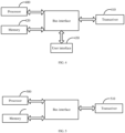
- the present disclosure provides a terminal device, comprising a memory, a transceiver, and a processor.
- the memory is configured to store a computer program.
- the transceiver is configured to receive and transmit information under control of the processor.
- the processor is configured to read the computer program in the memory and execute following steps:
- the specified parameter includes at least one of the following: a high-level parameter CORESETPoolIndex, a detected control resource set (CORESET) used to transmit the DCI or a physical downlink control channel (PDCCH), a transmission configuration indication (TCI) state configuration, a specified information field in the DCI, a capability value index of a terminal device, an SRS resource set index, a CG index, or a specified radio resource control (RRC) parameter.
- a high-level parameter CORESETPoolIndex a detected control resource set (CORESET) used to transmit the DCI or a physical downlink control channel (PDCCH), a transmission configuration indication (TCI) state configuration, a specified information field in the DCI, a capability value index of a terminal device, an SRS resource set index, a CG index, or a specified radio resource control (RRC) parameter.
- the indication information includes at least one of the following:
- the specified information field in the DCI includes at least one of the following:
- the indication information includes the CORESETPoolIndex configured in the high-level parameter of the SRS resource set, and the processor is specifically configured to:
- the indication information includes the SRS resource set index configured under the CORESET, and the processor is specifically configured to:
- the indication information includes the capability value index of the terminal device configured for the CORESET, and the processor is specifically configured to:
- the indication information includes the specified information field in the DCI, and the processor is specifically configured to:
- the indication information includes the specified information field in the DCI, and before obtaining the specified information field in the DCI, the processor is further configured to: transmit capability information for supporting the specified information field in the DCI to the network device.
- the indication information includes the TCI state configuration
- the processor is specifically configured to:
- the TCI state configuration associated with the DCI includes at least one of the following:
- the SRS resource set associated with the TCI state configuration includes at least one of the following:
- the specified parameter includes the detected CORESET used to transmit the DCI or the PDCCH, and the processor is specifically configured to:
- the association is determined based on the configured SRS resource set or based on the capability value index reported by the terminal device.
- the specified parameter includes the CORESET used to transmit the DCI or the physical downlink control channel (PDCCH)
- the association includes an association between the CORESET and the SRS resource set
- the processor is further configured to:
- the association includes a first relationship between the CORESET and the capability value index, and includes a second relationship between the capability value index and the SRS resource set, and the processor is further configured to:
- the processor is specifically configured to
- the indication information includes the CORESETPoolIndex configured in the high-level parameter of the SRS resource set, and the processor is specifically configured to:
- the indication information includes the SRS resource set index associated with the CG configuration or the SRI
- the processor is specifically configured to: determine an SRS resource set corresponding to the SRS resource set index associated with the CG configuration or the SRI for transmitting the PUSCH.
- the indication information includes the capability value index of the terminal device associated with the CG configuration or the SRI
- the processor is specifically configured to: determine an SRS resource set corresponding to the capability value index of the terminal device associated with the CG configuration or the SRI for transmitting the PUSCH.
- the indication information includes the TCI state configuration
- the processor is specifically configured to:
- the association includes:
- the association between the CG index configured in the CG configuration and the SRS resource set includes: an odd CG index corresponds to one SRS resource set of two SRS resource sets configured by the network device, and an even CG index corresponds to the other SRS resource set.
- the CG configuration includes a second CG index of another associated CG.
- the association between the specified RRC parameter configured in the CG configuration and the SRS resource set includes:
- the CG configuration does not include information associated with other CGs, and the association includes: the CG configuration corresponds to one SRS resource set of a plurality of SRS resource sets configured by the network device.
- the transceiver is configured to receive and transmit information under control of the processor.
- the processor is configured to read the computer program in the memory and execute following steps:
- the specified parameter includes at least one of the following: a high-level parameter CORESETPoolIndex, a detected CORESET used to transmit DCI or a physical downlink control channel (PDCCH), a transmission configuration indication (TCI) state configuration, a specified information field in the DCI, a capability value index of the terminal device, an SRS resource set index, a CG index, or a specified radio resource control (RRC) parameter.
- the indication information includes at least one of the following:
- the specified information field in the DCI includes at least one of the following:
- the processor is further configured to:
- the indication information includes the TCI state configuration
- the processor is specifically configured to:
- the processor is further configured to: configure at least two PUSCH transmission parameters for the terminal device, wherein values of the at least two PUSCH transmission parameters is the same or different.
- the processor is further configured to: configure CG indexes of other associated CGs in the CG configuration.
- a transmission apparatus for a physical uplink shared channel comprises:
- the specified parameter includes at least one of the following: a high-level parameter CORESETPoolIndex, a detected CORESET used to transmit DCI or a physical downlink control channel (PDCCH), a transmission configuration indication (TCI) state configuration, a specified information field in the DCI, a capability value index of the terminal device, an SRS resource set index, a CG index, or a specified radio resource control (RRC) parameter.
- the indication information includes at least one of the following:
- the specified information field in the DCI includes at least one of the following:
- the indication information includes the CORESETPoolIndex configured in the high-level parameter of the SRS resource set, and the resource set determining module is specifically configured to:
- the indication information includes the SRS resource set index configured under the CORESET, and the resource set determining module is specifically configured to:
- the indication information includes the capability value index of the terminal device configured for the CORESET, and the resource set determining module is specifically configured to:
- the indication information includes the specified information field in the DCI, and the resource set determining module is specifically configured to:
- the indication information includes the TCI state configuration, and the resource set determining module is specifically configured to:
- the TCI state configuration associated with the DCI includes at least one of the following:
- the SRS resource set associated with the TCI state configuration includes at least one of the following:
- the specified parameter includes the detected CORESET used to transmit the DCI or the PDCCH, and the resource set determining module is specifically configured to:
- the association is determined based on the configured SRS resource set or based on the capability value index reported by the terminal device.
- the specified parameter includes the CORESET used to transmit the DCI or the physical downlink control channel (PDCCH), and the association includes an association between the CORESET and the SRS resource set.
- the apparatus further comprises:
- the association in a case that the specified parameter includes the CORESET, the association includes a first relationship between the CORESET and the capability value index, and includes a second relationship between the capability value index and the SRS resource set.
- the apparatus further comprises:
- the resource set determining module is specifically configured to:
- the indication information includes the CORESETPoolIndex configured in the high-level parameter of the SRS resource set, and the resource set determining module is specifically configured to:
- the indication information includes the SRS resource set index associated with the CG configuration or the SRI
- the resource set determining module is specifically configured to: determine an SRS resource set corresponding to the SRS resource set index associated with the CG configuration or the SRI for transmitting the PUSCH.
- the indication information includes the capability value index of the terminal device associated with the CG configuration or the SRI
- the resource set determining module is specifically configured to: determine an SRS resource set corresponding to the capability value index of the terminal device associated with the CG configuration or the SRI for transmitting the PUSCH.
- the indication information includes the TCI state configuration, and the resource set determining module is specifically configured to:
- the association includes:
- the association between the CG index configured in the CG configuration and the SRS resource set includes: an odd CG index corresponds to one SRS resource set of two SRS resource sets configured by the network device, and an even CG index corresponds to the other SRS resource set.
- the CG configuration includes a second CG index of another associated CG.
- the association between the specified RRC parameter configured in the CG configuration and the SRS resource set includes:
- the association between the specified RRC parameter configured in the CG configuration and the SRS resource set includes: a first RRC parameter configured in the CG configuration corresponds to one SRS resource set of two SRS resource sets configured by the network device, and a second RRC parameter corresponds to the other SRS resource set; wherein one or two of the first RRC parameter and the second RRC parameter are configured in the CG configuration.
- the CG configuration does not include information associated with other CGs, and the association includes: the CG configuration corresponds to one SRS resource set of a plurality of SRS resource sets configured by the network device.
- the present disclosure further provides a transmission apparatus for a physical uplink shared channel, comprising:
- the specified parameter includes at least one of the following: a high-level parameter CORESETPoolIndex, a detected CORESET used to transmit DCI or a physical downlink control channel (PDCCH), a transmission configuration indication (TCI) state configuration, a specified information field in the DCI, a capability value index of the terminal device, an SRS resource set index, a CG index, or a specified radio resource control (RRC) parameter.
- the indication information includes at least one of the following:
- the specified information field in the DCI includes at least one of the following:
- the apparatus further includes: a receiving module, configured to receive capability information about whether the specified information field in the DCI is supported transmitted by the terminal device.
- the configuring module is specifically configured to configure, in a case that the capability information indicates that the terminal device supports the specified information field in the DCI, the indication information based on the specified information field in the DCI.
- the indication information includes the TCI state configuration, and then the configuring module is specifically configured to:
- the configuring module is further configured to: configure at least two PUSCH transmission parameters for the terminal device, wherein values of the at least two PUSCH transmission parameters is the same or different.
- the configuring module is further configured to: configure CG indexes of other associated CGs in the CG configuration.
- an embodiment of the present disclosure provides a computer readable storage medium, storing a computer program therein.
- a processor executes the computer program, the method according to any one of the first aspect and second aspect is implemented.
- an embodiment of the present disclosure provides a computer program product, comprising a computer program code.
- a computer program product comprising a computer program code.
- a term "and/or" describes an association of associated objects, which means that there may be three kinds of relationships, for example, A and/or B may mean that there are three kinds of situations: A alone, A and B at the same time, and B alone.
- a character "/" universally indicates that front and back associated objects are in an "or” relationship.
- a term "a plurality of” in the embodiments of the present disclosure means two or more, and other quantifiers are similar to it.
- a terminal device involved in the embodiments of the present disclosure may be a device that provides voice and/or data connectivity to a user, a handheld device with a wireless connection function, or other processing devices connected to a wireless modem, etc.
- names of terminal devices may also be different.
- the terminal devices may be called user equipment (UE).
- a wireless terminal device may communicate with one or more core networks (CNs) via a radio access network (RAN) and may be a mobile terminal device such as a mobile phone (or a "cellular" phone) and a computer with a mobile terminal device, for example, a portable, pocket-sized, handheld, computer-built-in, or vehicle-mounted mobile apparatus that exchanges language and/or data with the RAN, and for example, a personal communication service (PCS) phone, a cordless phone, a session initiated protocol (SIP) phone, a wireless local loop (WLL) station, a personal digital assistant (PDA), and other devices.
- PCS personal communication service
- SIP session initiated protocol
- WLL wireless local loop
- PDA personal digital assistant
- the wireless terminal device may also be called a system, a subscriber unit, a subscriber station, a mobile station, a mobile, a remote station, an access point, a remote terminal, an access terminal, a user terminal, a user agent, and a user device, which is not limited in the embodiments of the present disclosure.
- a network device involved in the embodiments of the present disclosure may be a base station which may include a plurality of cells that provide services to a terminal.
- the base station may also be called an access point, or may be a device in an access network that communicates with a wireless terminal device through one or more sectors on an air interface, or other names.
- the network device may be configured to interchange a received air frame with an Internet protocol (IP) packet, acting as a router between the wireless terminal device and the rest of the access network, wherein the rest of the access network may include an Internet protocol (IP) communication network.
- IP Internet protocol
- the network device may also coordinate management of attributes of the air interface.
- the network device involved in the embodiments of the present disclosure may be a network device (a base transceiver station (BTS)) in a global system for mobile communications (GSM) or code division multiple access (CDMA), may also be a network device (NodeB) in wide-band code division multiple access (WCDMA), may further be an evolutional network device (an evolutional Node B, eNB or e-NodeB) in a long term evolution (LTE) system, a 5G base station (gNB) in a 5G network architecture (a next generation system), and may also be a home evolved base station (a home evolved Node B, HeNB), a relay node, a home base station (a femto), a pico base station (a pico), etc., which is not limited in the embodiments of the present disclosure.
- the network device may include a centralized unit (CU) node and a distributed unit (DU) node, and a centralized unit and a distributed unit may also be geographical
- Multi input multi output (MIMO) transmission may be performed between the network device and the terminal device by using one or more antennas each, and the MIMO transmission may be single user MIMO (SU-MIMO) or multiple user MIMO (MU-MIMO). According to the shape and number of root antenna combinations, the MIMO transmission may be 2D-MIMO, 3D-MIMO, FD-MIMO, or massive-MIMO, or may be diversity transmission or precoded transmission or beam forming transmission, etc.
- SU-MIMO single user MIMO
- MU-MIMO multiple user MIMO
- the MIMO transmission may be 2D-MIMO, 3D-MIMO, FD-MIMO, or massive-MIMO, or may be diversity transmission or precoded transmission or beam forming transmission, etc.
- the PUSCH When the PUSCH is scheduled independently by using a multi-DCI framework, or the PUSCH is transmitted simultaneously through a plurality of CG configurations, or the PUSCH is scheduled through the DCI and the PUSCH is transmitted through the configured grant (CG) configuration simultaneously, if a plurality of SRS resource sets are configured, which SRS resource set the SRI indicated by the SRI in the DCI or the CG configuration acts on cannot be determined by the terminal device. As a result, correct transmission of the PUSCH cannot be effectively ensured, and a transmission performance is reduced.
- CG configured grant
- the SRS resource set determined by the terminal device may not be consistent with the SRS resource set understood by a network side. As a result, the correct transmission of the PUSCH cannot be effectively ensured.
- the terminal device transmits the PUSCH through the plurality of CG configurations simultaneously, if it is determined that all the CG configurations are associated with a first SRS resource set, since each SRS resource set is usually associated with a panel (antenna panel), as a result, the PUSCH may be transmitted simultaneously by the terminal device only through one single panel, and thus the transmission performance of the PUSCH is reduced.
- an embodiment of the present disclosure proposes a transmission method for a PUSCH, a device, and a storage medium.
- an SRS resource set used to transmit the PUSCH may be understood by a terminal device according to a predefined rule, i.e., which PUSCH the SRS resource set acts on is determined.
- a predefined rule i.e., which PUSCH the SRS resource set acts on is determined.
- the PUSCH When the PUSCH is scheduled through the DCI and the PUSCH is transmitted through the CG configuration simultaneously, or the PUSCH is transmitted through a plurality of CG configurations, different SRS resource sets may be determined, thus it is ensured that a plurality of panels perform transmission simultaneously, and improving the transmission performance of the PUSCH.
- the network device may indicate which SRS resource set is adopted to the terminal device.
- This indication mode may be explicit or implicit, thereby also ensuring correct transmission of the PUSCH, and improving the transmission performance of the PUSCH.
- the transmission method for the PUSCH provided by the embodiment of the present disclosure is described below by way of specific implementations. For ease of understanding, modes of determining the SRS resource set based on the predefined rule and/or determining the SRS resource set based on an indication are described below respectively.
- An SRS resource set is determined based on a predefined rule
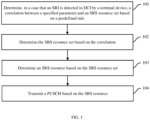
- FIG. 1 is a flowchart of a method for determining an SRS resource set by a terminal device based on a predefined rule
- the method is applied to a scenario in which at least one piece of DCI schedules a PUSCH, and comprises the following steps.
- Step 101 in a case that the terminal device detects an SRI in the DCI, determining an association between a specified parameter and the SRS resource set based on a predefined rule. In addition, in step 102, determining the SRS resource set based on the association.
- the predefined rule is used to determine the association between the specified parameter and the SRS resource set.
- the specified parameter includes at least one of the following: a high-level parameter CORESETPoolIndex, a detected control resource set (CORESET) used to transmit the DCI or a physical downlink control channel (PDCCH), a transmission configuration indication (TCI) state configuration, a specified information field in the DCI, or a capability value index of the terminal device.
- the capability value index of the terminal device above is a capability value related to a panel (antenna panel) of the terminal device, and the capability value is used to indicate a maximum number of SRS antenna ports.
- a panel-related capability value set index: capability [set] index may be reported by the terminal device, and the capability value set index may also be referred to simply as a capability value index.
- Each capability value index includes a maximum number of supported SRS ports (which may also be referred to as a capability value), and any two capability value indexes correspond to different numbers of SRS ports.
- How many panels of SRS ports the terminal has may be determined by a network side device according to the capability value index reported by the terminal. For example, the terminal device has three panels with 2, 2, and 4 SRS antenna ports respectively, and then 2 capability value indexes may be reported by the terminal device and correspond to 2 SRS ports and 4 SRS ports respectively.
- the network side may determine that the terminal device at least has 2-port and 4-port panels after receiving the capability value indexes reported by the terminal device. In Rel-17, the capability value index reported by the terminal may only be used for beam measurement reporting.
- Example 1) to Example 5) are given below to illustrate how a terminal device determines an SRS resource set based on a predefined rule and an association between a specified parameter and the SRS resource set.
- Example 1 when a specified parameter includes a CORESET, an SRS resource set is determined based on an association:
- the CORESET in the specified parameter and the SRS resource set have a default association.
- the SRS resource set When the SRS resource set is determined based on the association, it may be implemented as follows: the CORESET used to transmit DCI or a PDCCH is detected; and then an SRS resource set associated with the CORESET is selected from at least one SRS resource set for transmitting the PUSCH.
- the CORESET used to transmit the DCI or the PDCCH is first determined, and then the SRS resource set for the CORESET is determined based on the association.
- Example 2 when a specified parameter includes a CORESET and CORESETPoolIndex, an SRS resource set is determined based on an association: in this case, it may be implemented as follows: the CORESET used to transmit DCI or a PDCCH is detected; and then an SRS resource set associated with the CORESET or the CORESETPoolIndex of the CORESET is selected from at least one SRS resource set used to transmit a PUSCH.
- a CORESET1 used to transmit the DCI or the PDCCH may be determined first, then CORESETPoolIndex1 of the CORESET1 is determined, and then an SRS resource set associated with the CORESETPoolIndex1 is selected for subsequent transmission of the PUSCH.
- an SRS resource is determined based on an association of a CORESET or CORESETPoolIndex:
- the association between the specified parameter in the predefined rule and the SRS resource set may be determined based on the configured SRS resource set or based on the capability value index reported by the terminal device.
- determining the association based on the configured SRS resource set may be implemented as follows:
- the second specified CORESET is associated with a first SRS resource set and a second SRS resource set
- the third specified CORESET is associated with a third SRS resource set and a fourth SRS resource set.
- the second specified CORESET is associated with the first SRS resource set and the third SRS resource set
- the third specified CORESET is associated with the second SRS resource set and the fourth SRS resource set.
- the second specified CORESET is associated with the first SRS resource set to an Nth SRS resource set
- the third specified CORESET is associated with an (N+1)th SRS resource set to a 2Nth or Mth SRS resource set.
- the second specified CORESET is associated with the first SRS resource set, the third SRS resource set, ..., to a (2N-1)th or (2N+1)th SRS resource set
- the third specified CORESET is associated with the second SRS resource set, the fourth SRS resource set, ..., and the 2Nth SRS resource set.
- the network device configures one SRS resource set for the terminal device
- the one SRS resource set is associated with the first specified CORESET, or the one SRS resource set is associated with all CORESETs.
- a-2-2 two SRS resource sets are configured.
- the CORESET not configured with the CORESETPoolIndex or the CORESET whose CORESETPoolIndex value is 0 corresponds to one SRS resource set of the two SRS resource sets, and the CORESET whose CORESETPoolIndex value is 1 corresponds to the other SRS resource set.
- the two SRS resource sets are an SRS resource set 1 and an SRS resource set 2, then the SRS resource set 1 is associated with the CORESET whose CORESETPoolIndex value is 0, and the SRS resource set 2 is associated with the CORESET whose CORESETPoolIndex value is 1.
- a-2-3 a plurality of SRS resource sets are configured.
- the CORESET not configured with the CORESETPoolIndex or the CORESET whose CORESETPoolIndex value is 0 corresponds to the first SRS resource set and the second SRS resource set
- the CORESET whose CORESETPoolIndex value is 1 corresponds to the third SRS resource set and the fourth SRS resource set.
- the predefined rule specifies that the one SRS resource set is associated with all CORESETs, or with some CORESETs, or with the CORESET not configured with the CORESETPoolIndex, or with the CORESET whose CORESETPoolIndex value is 0, or with the CORESET whose CORESETPoolIndex value is 1.
- each SRS resource set is associated with one or more CORESET or CORESETPoolIndex by default.
- a following assumption is made about how to establish a predefined rule according to the number of SRS resource sets. If a parameter srs-ResourceSetToAddModList or srs-ResourceSetToAddModListDCI-0-2 is configured with two SRS resource sets for 'codebook' or 'noncodebook' usage, the first SRS resource set is associated with the CORESET whose CORESETPoolIndex value is 0, and the second SRS resource set is associated with the CORESET whose CORESETPoolIndex value is 1.
- the parameter srs-ResourceSetToAddModList or srs-ResourceSetToAddModListDCI-0-2 is configured with three or four SRS resource sets for 'codebook' or 'noncodebook' usage
- the first and/or the third SRS resource set is associated with the CORESET whose CORESETPoolIndex value is
- the second and/or the fourth SRS resource set is associated with the CORESET whose CORESETPoolIndex value is 1.
- the CORESET whose CORESETPoolIndex value is 0 and the CORESET whose CORESETPoolIndex value is 1 may also be interchanged.
- the CORESET whose CORESETPoolIndex value is 0 contains both a CORESET that is configured with CORESETPoolindex with the parameter value of 0, and a CORESET that is not configured with the CORESETPoolindex parameter.
- a parameter srs-ResourceSetId For example, when a high-level parameter 'txconfig' is configured as 'codebook', the first SRS resource set is an SRS resource set with a lowest srs-ResourceSetId value in SRS resource sets whose usage is 'codebook'.
- the high-level parameter 'txconfig' is configured as 'noncodebook', the first SRS resource set is an SRS resource set with a lowest srs-ResourceSetId value in SRS resource sets whose usage is 'noncodebook'.
- the SRS resource set associated with the CORESET may be determined according to the above predefined rule, and thus the corresponding SRS resource as well as a transmission port of the PUSCH are determined according to an indication of the SRI. For example, when the SRS resource set for transmitting the PUSCH is determined, the CORESET used to transmit the DCI may be detected first, and then if the predefined rule is the association between the CORESET and the SRS resource set, the SRS resource set for transmitting the PUSCH may be determined based on the association.
- the network device configures one SRS resource set for the terminal device
- the one SRS resource set is associated with the first specified CORESETPoolIndex value, or the one SRS resource set is associated with all CORESETPoolIndex values.
- two SRS resource sets are configured.
- the second specified CORESETPoolIndex value corresponds to one SRS resource set of the two SRS resource sets
- the third specified CORESETPoolIndex value corresponds to the other SRS resource set.
- the second specified CORESETPoolIndex value corresponds to the first SRS resource set and the second SRS resource set
- the third specified CORESETPoolIndex value corresponds to the third SRS resource set and the fourth SRS resource set.
- the SRS resource set the DCI acts on may be determined by the terminal according to the CORESETPoolIndex value of the CORESET where the DCI is detected, and thus a corresponding SRS resource is determined to be used for transmission of the PUSCH.
- the terminal device reports one capability value index
- the one capability value index and a second specified CORESET or all CORESETs establish the first relationship
- the one capability value index and a specified SRS resource set establish the second relationship.
- the capability value index When one capability value index is reported, by default the capability value index has the first relationship with the CORESET whose CORESETPoolindex value is 0, or by default the one capability value index has the first relationship with all CORESETs, and then the one capability value index has the second relationship with the specified SRS resource set.
- the SRS resource set is determined, the CORESET where the DCI or PDCCH is detected is first determined, then the capability value corresponding to the CORESET is determined based on the first relationship, and then the SRS resource set corresponding to the capability value is determined based on the second relationship.
- c-2 a case that the terminal device reports a plurality of capability value indexes
- the first relationship is established between a part of the plurality of capability values indexes and a CORESET that is not configured with CORESETPoolIndex or a CORESET whose CORESETPoolIndex value is a first value
- the first relationship is established between a remaining other part of the plurality of capability value indexes and a CORESET whose CORESETPoolIndex value is a second value
- the second relationship is established between each capability value index and an SRS resource set specified by each capability value index.
- the terminal device reports a plurality of capability value indexes
- a first capability value is associated with a CORESET whose CORESETPoolindex value is 0 or a CORESET that is not configured with a parameter CORESETPoolindex
- a second capability value is associated with a CORESET whose CORESETPoolindex value is 1.
- the first capability value is associated with a CORESET whose CORESETPoolindex value is 1
- the second capability value is associated with a CORESET whose CORESETPoolindex value is 0 or a CORESET that is not configured with a parameter CORESETPoolindex.
- the 2nth (n 0, 1, 2, ...
- capability value is associated with a CORESET whose CORESETPoolindex value is 0 or a CORESET that is not configured with a parameter CORESETPoolindex.
- the terminal device reports one capability value index
- the one capability value index and a second specified CORESETPoolIndex value or all CORESETPoolIndex values establish the first relationship
- the one capability value index and a specified SRS resource set establish the second relationship.
- the second specified CORESETPoolIndex value may be 0 or 1.
- the first relationship is established between a part of the plurality of capability value indexes and a third specified CORESETPoolIndex value, and the first relationship is established between the remaining other part of the plurality of the capability value indexes and a fourth specified CORESETPoolIndex value.
- the third specified CORESETPoolIndex value may be 0 or 1
- the fourth specified CORESETPoolIndex value may be 1 or 0.
- the CORESETPoolIndex value of the CORESET where the DCI or PDCCH is detected is first determined, then the corresponding capability value is determined based on the CORESETPoolIndex value, and then the corresponding SRS resource set is determined based on the association of the capability value and the SRS resource set.
- the following is a further example of how to determine the SRS resource set based on the association determined by the capability value.
- the capability value is associated with a CORESET whose CORESETPoolindex value is 0.
- a first capability value is associated with a CORESET whose CORESETPoolindex value is 0, and a second capability value is associated with a CORESET whose CORESETPoolindex value is 1.
- the CORESET whose CORESETPoolIndex value is 0 and the CORESET whose CORESETPoolIndex value is 1 may also be interchanged.
- the capacity value associated with the CORESET may be determined according to the above predefined rule, thus a maximum SRS port corresponding to the capability value as well as the SRS resource set are determined, and the corresponding SRS resource as well as a transmission port of the PUSCH are determined according to an indication of the SRI.
- an SRS resource is determined based on a TCI state configuration in a specified parameter and a predefined rule: different TCI state configurations may be predefined to associate different SRS resource sets.
- the TCI state configuration may be a state bit in a TCI field in the DCI.
- a TCI field indicates N TCI states.
- the predefined rule may be that each TCI state bit corresponds to an SRS resource set.
- the TCI field indicates four TCI states, wherein a first TCI state bit and a second TCI state bit are used for a downlink TCI state indication, and a third TCI state bit and a fourth TCI state bit are used for an uplink TCI state indication.
- the terminal may determine that the third TCI state bit is associated with the first SRS resource set and the fourth TCI state bit is associated with the second SRS resource set.
- the TCI state bit When an indication of the TCI state bit is a first particular value (e.g., '111') or a reserved value ('Reserved'), then it means that the TCI state bit is not used. When an indication of the TCI state bit is a second particular value (e.g., '000' to '110'), then it means that the TCI state bit indicates a specific TCI state.
- the SRS resource set the DCI acts on may be determined by the terminal according to the indication of the TCI in the DCI and an association of the TCI state bit with the SRS resource set, and thus the corresponding SRS resource is determined for transmission of the PUSCH.
- one or more TCI state bits each correspond to one SRS resource set.
- an SRS resource set field or another information field is used to indicate which information bit is activated, e.g., a first TCI state bit is activated, or a second TCI state bit is activated, or two TCI state bits are both activated. If the SRS resource set is used, e.g., when the SRS resource set indicates '0', it means that the first TCI state is activated. When the SRS resource set indicates '1', it means that the second TCI state is activated.
- an SRS resource set is determined based on a capability value index in a specified parameter: different capability value indexes may be predefined to associate different SRS resource sets.
- the capability value reported by the terminal device may be first determined, and then which SRS resource set is adopted to determine the SRS resource may be determined according to the predefined rule.
- a first capability value index is associated with an SRS resource set 0, and a second capability value index is associated with an SRS resource set 1.
- the first capability value index and the second capability value index are sorted from smallest to largest or from largest to smallest respectively in accordance with values of SRS ports. For example, the number of SRS ports corresponding to the capability value indexes reported by the terminal are 2 and 4 respectively, then the first capability value index refers to the capability value index for the number of SRS ports of 2, and the second capability value index refers to the capability value index for the number of SRS ports of 4.
- the terminal reports a capability value index (e.g. a corresponding CORESETPoolIndex value is 0 or 1) for scheduling of each transmission and receiving point (TRP) respectively, and thus an SRS resource set corresponding to the scheduling of the TRP may be determined by both the network device and the terminal.
- a capability value index e.g. a corresponding CORESETPoolIndex value is 0 or 1
- Step 103 determining an SRS resource based on the SRS resource set.
- the SRS resource is determined based on the SRI field in the DCI.
- Step 104 transmitting the PUSCH based on the SRS resource.
- the adopted predefined rules may be determined according to actual needs during implementation.
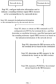
- FIG. 2 which is a flowchart of a method for determining an SRS resource set by a terminal device based on a predefined rule, the method is applied to a scenario where a PUSCH is transmitted through at least one CG configuration and includes the following steps 201-204.
- Step 201 in a case that the terminal device obtains an SRI included in the CG configuration, determining an association between a specified parameter and the SRS resource set based on the predefined rule. In addition, in step 202, determining the SRS resource set based on the association.
- the predefined rule is used to determine the association between the specified parameter and the SRS resource set.
- the specified parameter includes at least one of the following: a high-level parameter CORESETPoolIndex, a transmission configuration indication (TCI) state configuration, a capability value index of the terminal device, an SRS resource set index, a CG index, or a specified radio resource control (RRC) parameter.
- TCI transmission configuration indication
- RRC radio resource control
- the above specified parameters may be configured by RRC parameters.
- the RRC parameters may be configured under rrc-ConfiguredUplinkGrant or under srs-ResourceIndicator or srs-ResourceIndicator2-r17.
- the SRI included in the CG configuration may be configured by srs-ResourceIndicator or srs-ResourceIndicator2-r17, and indicates the SRS resource in the SRS resource set with which it is associated.
- the CG index may be a CG configuration ID, such as configuredGrantConfigIndex-r16 (32 at most).
- determining the SRS resource set based on the association may be implemented as follows.
- the CORESETPoolIndex associated with the CG configuration or the SRI is obtained. selecting an SRS resource set whose CORESETPoolIndex configured in the high-level parameter of the SRS resource set is the same as the CORESETPoolIndex associated with the CG configuration or the SRI from at least one SRS resource set for transmitting the PUSCH.
- a CORESETPoolINdex value associated with a CG configuration or an SRI may be configured under the CG configuration or the SRI, and the SRS resource set is also associated with a CORESETPoolINdex value, so the CG configuration or the SRI and the SRS resource set associated with the same CORESETPoolINdex value are associated.
- a CG configuration includes an SRI (srs-ResourceIndicator or srs-ResourceIndicator2-r17)
- the SRS resource set corresponding to the CORESETPoolIndex value associated with the CG configuration is the SRS resource set associated with the SRI.
- each SRI may be associated with different CORESETPoolIndex values respectively, i.e., associated with different SRS resource sets.
- determining the SRS resource set based on the association may be implemented as follows. An SRS resource set corresponding to the SRS resource set index associated with the CG configuration or the SRI is used for transmitting the PUSCH.
- an SRS resource set index associated therewith may be configured and may correspond to a high-level parameter srs-ResourceSetId. If a CG configuration includes an SRI, the SRS resource set corresponding to the SRS resource set index associated with the CG configuration is the SRS resource set associated with the SRI. If a CG includes a plurality of SRIs, each SRI may be respectively associated with different SRS resource set indexes, i.e., associated with different SRS resource sets.
- determining the SRS resource set based on the association may be implemented as follows. An SRS resource set corresponding to the capability value index of the terminal device associated with the CG configuration or the SRI is determined for transmitting the PUSCH.
- the capability value index of the terminal device associated therewith may be configured, and the SRS resource set is also associated with a capability value index, so that the CG configuration or the SRI and the SRS resource set associated with the same capability value index are associated.
- the SRS resource set corresponding to the capability value index associated with the CG configuration is the SRS resource set associated with the SRI.
- each SRI may be associated with different capability value indexes respectively, i.e., associated with different SRS resource sets.
- An associated TCI state may be configured under a CG configuration or an SRI, and the SRS resource set is also associated with a TCI state (e.g. a first TCI state configured or indicated, or a second TCI state, etc.), so the CG configuration or the SRI and the SRS resource set associated with the same TCI state are associated.
- a CG configuration includes an SRI
- the SRS resource set corresponding to the TCI state associated with the CG configuration is the SRS resource set associated with the SRI.
- each SRI may be associated with different TCI states respectively, i.e., associated with different SRS resource sets.
- the association may include: an association between the CG index configured in the CG configuration and the SRS resource set.
- the CG index configured in the CG configuration may be understood as a specified RRC parameter.
- the association between the CG index configured in the CG configuration and the SRS resource set includes that: an odd CG index corresponds to one SRS resource set of two SRS resource sets configured by the network device, and an even CG index corresponds to the other SRS resource set.
- the CG index (configuredGrantConfigIndex-r16) has a predefined correspondence with the SRS resource set index, the odd CG index corresponds to a first SRS resource set, and the even CG index corresponds to a second SRS resource set.
- the corresponding SRS resource set may be determined according to the CG index configured in the CG configuration.
- the association may include: an association between the specified RRC parameter configured in the CG configuration and the SRS resource set.
- the CG configuration includes a second CG index of another associated CG
- the association between the specified RRC parameter configured in the CG configuration and the SRS resource set includes the following two cases.
- a first CG index corresponding to the CG configuration is smaller than the second CG index, then the first CG index corresponds to a first SRS resource set of two SRS resource sets configured by the network device.
- the first CG index corresponding to the CG configuration is greater than the second CG index, then the first CG index corresponds to a second SRS resource set of the two SRS resource sets configured by the network device.
- the second CG index of another associated CG in the CG configuration may be understood as the specified RRC parameter, or both the first CG index and the second CG index may be understood as specified RRC parameters associated with two SRS resource sets respectively.
- the association includes that: the CG configuration corresponds to one SRS resource set, e.g. a first SRS resource set, of a plurality of SRS resource sets configured by the network device.
- an association between two CGs may be pre-established by the network device.
- the network device configures that a combination of some of CGs may do simultaneous transmission (or repetitive transmission).
- the CG configuration includes an ID of the CG, and an ID of a CG that jointly performs simultaneous transmission or repetitive transmission with the CG, such as the following configuration code: wherein associatedconfiguredGrantConfigIndex is used to configure the CG indexes of other associated CGs.
- the CG with a lower CG index may be associated with the first SRS resource set, and the CG with a higher CG index may be associated with the second SRS resource set.
- a CG that is not associated with other CGs may be associated with only the first SRS resource set.
- the association between the specified RRC parameter configured in the CG configuration and the SRS resource set includes that: a first RRC parameter configured in the CG configuration corresponds to one SRS resource set of two SRS resource sets configured by the network device, and a second RRC parameter corresponds to the other SRS resource set; wherein one or two of the first RRC parameter and the second RRC parameter are configured in the CG configuration.
- the first RRC parameter corresponds to a first SRI (srs-ResourceIndicator)
- the first SRI indication corresponds to the first SRS resource set
- the second RRC parameter corresponds to a second SRI (srs-ResourceIndicator2-r17)
- the second SRI corresponds to the second SRS resource set.
- the network device may configure only srs-ResourceIndicator or srs-ResourceIndicator2-r17, or both srs-ResourceIndicator and srs-ResourceIndicator2-r17 under the CG configuration.
- Step 203 determining an SRS resource based on the SRS resource set.
- the SRS resource is determined based on the SRI in the CG configuration.
- the SRI (srs-ResourceIndicator or srs-ResourceIndicator2-r17) indicates the SRS resource in the SRS resource set associated therewith.
- Step 204 transmitting the PUSCH based on the SRS resource.
- the method for determining the SRS resource set by the terminal device based on the predefined rule may further be applied to a scenario in which a PUSCH is scheduled through DCI and a PUSCH is transmitted through a CG configuration simultaneously.
- an SRS resource set may be determined by the method shown in FIG. 1 in the above embodiment.
- an SRS resource set may be determined by the method shown in FIG. 2 in the above embodiment, which will not be repeated here.
- Step 301 the network device configures the indication information used to indicate the sounding reference signal (SRS) resource set for the terminal device.
- SRS sounding reference signal
- the indication information of the network device is used to determine an association between a specified parameter and the SRS resource set.
- the specified parameter includes at least one of the following: CORESETPoolIndex, a detected CORESET used to transmit the DCI or the PDCCH, a TCI state configuration, a specified information field in the DCI, a capability value index of the terminal device, an SRS resource set index, a CG index, or a specified radio resource control (RRC) parameter.
- the indication information of the network device includes at least one of 1) to 8) below. 1), CORESETPoolIndex configured in a high-level parameter of the SRS resource set.
- the SRS resource set indicated by the indication information may be obtained through the high-level parameter of the SRS resource set during implementation.
- determining the SRS resource set by the terminal device according to the association may be implemented as follows.
- the CORESET used to transmit the DCI or the PDCCH is detected.
- An SRS resource set whose CORESETPoolIndex configured in the high-level parameter of the SRS resource set is the same as the CORESETPoolIndex of the CORESET is selected from at least one SRS resource set for transmitting the PUSCH.
- the terminal device obtains an SRI included in the CG configuration, and determining the SRS resource set may be implemented as follows.
- the CORESETPoolIndex associated with the CG configuration or the SRI is obtained.
- a CORESETPoolINdex value associated with a CG configuration or an SRI may be configured under the CG configuration or the SRI, and the SRS resource set is also associated with a CORESETPoolINdex value, so the CG configuration or the SRI and the SRS resource set associated with the same CORESETPoolINdex value are associated.
- a CG configuration includes an SRI (srs-ResourceIndicator or srs-ResourceIndicator2-r17)
- the SRS resource set corresponding to the CORESETPoolIndex value associated with the CG configuration is the SRS resource set associated with the SRI.
- each SRI may be associated with different CORESETPoolIndex values respectively, i.e., associated with different SRS resource sets.
- the high-level parameter corresponding to the SRS resource set is SRS-ResourceSet, configured in a parameter srs-ResourceSetToAddModList or srs-ResourceSetToAddModListDCI-0-2, and the usage of the SRS resource set is configured as 'codebook' or 'nonCodebook'.
- the parameter srs-ResourceSetToAddModList or srs-ResourceSetToAddModListDCI-0-2 corresponds to a DCI format 0_1 or 0_2 respectively, and two or more SRS resource sets with usage of 'codebook' or 'nonCodebook' may be configured.
- the SRI is an 'SRS resource indicator' field or a 'Second SRS resource indicator' field and may be carried by the DCI format 0_1 or 0_2, and a DCI format 0_0 has no SRI.
- the associated CORESETPoolIndex parameter is configured under the high-level parameter SRS-ResourceSet corresponding to the SRS resource set.
- the associated CORESETPoolIndex parameter is configured only under the high-level parameter SRS-ResourceSet corresponding to the SRS resource set with usage of 'codebook' or 'nonCodebook'. That is, a condition for configuring the CORESETPoolIndex parameter under the SRS-ResourceSet is that the usage of the SRS-ResourceSet is 'codebook' or 'nonCodebook'. For the SRS resource set with the usage of 'codebook' or 'nonCodebook', if the parameter CORESETPoolIndex is not configured, it may also be considered that a value of the CORESETPoolIndex is 0.
- the terminal may determine the SRS resource set, associated with the SRI, whose CORESETPoolIndex value is k and whose usage is also 'codebook' or 'nonCodebook' at the same time.
- the above method is applicable for all cases that one or more SRS resource sets with usage 'codebook' or 'nonCodebook' are configured in the high-level parameter srs-ResourceSetToAddModList or srs-ResourceSetToAddModListDCI-0-2.
- the terminal expects that there is no more than one SRS resource set whose usage is 'codebook' or 'nonCodebook' and whose CORESETPoolIndex value is k within a BWP or a cell, or that there is no more than one SRS resource set whose usage is 'codebook' or 'nonCodebook' and whose CORESETPoolIndex value is k configured in the high-level parameter srs-ResourceSetToAddModList or srs-ResourceSetToAddModListDCI-0-2.
- the SRS resource set associated with the SRI in the DCI may be determined by adopting this method in conjunction with other methods described later.
- the parameter CORESETPoolIndex may also be configured in an SRS resource set whose usage is 'beamManagement' or 'antennaSwitching' to indicate an association of this SRS resource set with a CORESET (TRP) for uplink beam management or uplink antenna switching, which facilitates subsequent multi-panel transmission.
- TRP CORESET
- the SRS resource set refers to an SRS resource set whose usage is 'codebook' or 'nonCodebook'.
- the SRS resource set may be determined by the terminal device according to the capability value index by configuring the capability value index of the terminal device under the CORESET.
- determining the SRS resource set may be implemented as follows.
- the CORESET used to transmit the DCI or the PDCCH is detected.
- the capability value index of the terminal device configured for the CORESET is obtained.
- An SRS resource set corresponding to the capability value index of the terminal device configured for the CORESET is determined for transmitting the PUSCH.
- a parameter Capability[Set]Index is configured under each CORESET, and UE determines a corresponding SRS resource set according to the number of SRS ports corresponding to the Capability[Set]Index (corresponding to the third case in mode II).
- a panel-related capability value (e.g., the parameter Capability[Set]Index) is configured below each CORESET to indicate that a certain panel of the UE may be scheduled for transmission by the CORESET.
- the numbers of SRS ports included in the SRS resource sets whose usage is 'codebook' or 'nonCodebook' configured in srs-ResourceSetToAddModList or srs-ResourceSetToAddModListDCI-0-2 are different, e.g.
- a capability value e.g., the capability value 2 associated with the SRI is determined according to the association, thus the number of associated SRS ports (four ports) is determined, and thus the SRS resource set (i.e., the SRS resource set 2) associated with the SRI is indirectly determined.
- the capability value index of the terminal device is determined based on the second information indication field, and then based on a pre-established association between the capability value index and the SRS resource set, the SRS resource set to be adopted may be determined.
- determining the SRS resource set by the terminal device may be implemented as follows.
- determining the SRS resource set may be implemented as follows.
- the TCI state configuration associated with the DCI is determined.
- An SRS resource set associated with the TCI state configuration is determined for transmitting the PUSCH.
- An SRS resource set associated with the TCI state configuration is determined for transmitting the PUSCH.
- the SRS resource set associated with the TCI state configuration includes at least one of the following:
- associations of different TCI state configurations with the SRS resource set is configured on the network side, and then the UE determines the (associated) SRS resource set the SRI acts on through the TCI state configurations.
- each TCI state is associated with an index of an SRS resource set.
- the SRS resource set index is included (similar to the Rel-16 TCI activation/update MAC CE carrying the CORESETPoolIndex parameter similarly).
- each TCI state bit corresponds to an SRS resource set (predefined rule)
- the indication of the other TCI state bit is a particular value, such as '111', which is equivalent to a reserved bit, and the terminal determines the SRS resource set the SRI acts on according to the TCI state indication.
- the SRS resource set index may be indicated by the network device to the terminal device, and then the SRS resource set may be determined by the terminal device according to the DCI and the resource set index.
- the SRS resource set index indicated by the network device includes the SRS resource set index configured for the CORESET.
- the CORESET used to transmit the DCI or the PDCCH may be detected by the terminal device.
- An SRS resource set corresponding to the SRS resource set index of the CORESET is used for transmitting the PUSCH.
- the associated SRS resource set index is configured under each CORESET, and each CORESET may be associated with an SRS resource set whose usage is codebook and/or non-codebook.
- the associated SRS resource set index may be configured in a high-level parameter ControlResourceSet corresponding to the CORESET.
- the SRS resource set index may be a high-level parameter srs-ResourceSetId, i.e., an absolute index of the SRS resource set (e.g., 0-15, sorted in a BWP), and may also be a relative index of the SRS resource set.
- the relative index is the first SRS resource set or the second SRS resource set, and these two indexes respectively correspond to the SRS resource set with a lower index or a higher index in the SRS resource set configured in srs-ResourceSetToAddModList or srs-ResourceSetToAddModListDCI-0-2 whose usage is 'codebook' or 'nonCodebook'.
- the terminal device may determine the SRS resource set associated with the SRI according to the CORESET where the DCI is located, and thus the corresponding SRS resource is determined.
- the SRS resource set indexes associated with CORESETs with the same CORESETPoolIndex parameter may be the same or different, and if they are the same, it means that one TRP is associated with one SRS resource set, i.e., this TRP only schedules this SRS resource set for transmission. If they are different, it means that a plurality of SRS resource sets may be scheduled for transmission by one TRP.
- the indication information includes the SRS resource set index associated with the CG configuration or the SRI, and when the terminal device obtains the SRI included in the CG configuration, determining the SRS resource set may be implemented as follows.
- An SRS resource set corresponding to the SRS resource set index associated with the CG configuration or the SRI is used for transmitting the PUSCH.
- an SRS resource set index associated therewith may be configured and may correspond to a high-level parameter srs-ResourceSetId. If a CG configuration includes an SRI, the SRS resource set corresponding to the SRS resource set index associated with the CG configuration is the SRS resource set associated with the SRI. If a CG includes a plurality of SRIs, each SRI may be respectively associated with different SRS resource set indexes, i.e., associated with different SRS resource sets.
- the indication information includes the capability value index of the terminal device associated with the CG configuration or the SRI, and when the terminal device obtains the SRI included in the CG configuration, determining the SRS resource set may be implemented as follows.
- An SRS resource set corresponding to the capability value index of the terminal device associated with the CG configuration or the SRI is determined for transmitting the PUSCH.
- the capability value index of the terminal device associated therewith may be configured, and the SRS resource set is also associated with a capability value index, so that the CG configuration or the SRI and the SRS resource set associated with the same capability value index are associated.
- the SRS resource set corresponding to the capability value index associated with the CG configuration is the SRS resource set associated with the SRI.
- each SRI may be associated with different capability value indexes respectively, i.e., associated with different SRS resource sets.
- the indication information includes the CG index associated in the CG configuration; and the association may include: an association between the CG index configured in the CG configuration and the SRS resource set.
- the CG index configured in the CG configuration may be understood as a specified RRC parameter.
- an association between the CG index configured in the CG configuration and the SRS resource set may be determined based on the following mode, and then the SRS resource set is determined based on the association: an odd CG index corresponds to one SRS resource set of two SRS resource sets configured by the network device, and an even CG index corresponds to the other SRS resource set.
- the association may include: an association between the specified RRC parameter configured in the CG configuration and the SRS resource set.
- the association between the specified RRC parameter configured in the CG configuration and the SRS resource set may be determined based on the following two cases, and then the SRS resource set is determined based on the association.
- a first CG index corresponding to the CG configuration is smaller than the second CG index, then the first CG index corresponds to a first SRS resource set of two SRS resource sets configured by the network device.
- the first CG index corresponding to the CG configuration is greater than the second CG index, then the first CG index corresponds to a second SRS resource set of the two SRS resource sets configured by the network device.
- the second CG index of another associated CG in the CG configuration may be understood as the specified RRC parameter, or both the first CG index and the second CG index may be understood as specified RRC parameters associated with two SRS resource sets respectively.
- the CG with a lower CG index may be associated with the first SRS resource set, and the CG with a higher CG index may be associated with the second SRS resource set.
- a CG that is not associated with other CGs may be associated with only the first SRS resource set.
- Step 305 the terminal device determines an SRS resource based on the SRS resource set.
- Step 306 the terminal device transmits the PUSCH based on the SRS resource.
- two PUSCH transmission parameters may be configured for the terminal device by the network device, and the two PUSCH transmission parameters take the same or different values.
- the terminal device may be scheduled by two pieces of DCI or PDCCHs (i.e., TRPs) independently to perform transmission by adopting different transmission methods.
- TRPs DCI or PDCCHs
- the terminal device is scheduled to perform transmission by adopting a codebook-based PUSCH transmission mode and a non-codebook-based PUSCH transmission mode respectively, thus the flexibility of scheduling of the network device is increased, and a system performance is improved.
- the SRS resource sets associated with two pieces of DCI are different when the SRS resource set is indicated dynamically using an 'SRS resource set' indication field or other information fields in the DCI signaling, i.e., the SRS resource sets whose usage is codebook and non-codebook respectively.
- the SRS resource sets indicated by the two pieces of DCI signaling are not in conflict, i.e., there is no situation where the PUSCH transmission corresponding to the two-DCI-indicated SRI resources exceed the capability of the terminal.
- an embodiment of the present disclosure further provides a terminal device, as shown in FIG. 4 , comprising: a transceiver 410, configured to receive and transmit data under control of a processor 400.
- a bus interface may include interconnected buses of any number and bridges of any number, which are specifically linked together through various circuits of one or more processors represented by the processor 400 and various circuits of memories represented by a memory 420.
- a bus architecture may also link various other circuits such as peripheral devices, voltage regulators, and power management circuits, which are well known in the field, and therefore are not further described herein.
- a bus interface provides an interface.
- the transceiver 410 may be a plurality of elements, i.e., it includes a transmitter and a receiver and provides units for communicating with various other devices over transmission media that include wireless channels, wired channels, optical cables, and other transmission media.
- the user interface 430 may further be an interface capable of externally and internally connecting desired devices.
- the connected devices include, but are not limited to, a keypad, a monitor, a speaker, a microphone, a joystick, etc.
- the processor 400 is responsible for managing the bus architecture and general processing, and the memory 420 may store data used when the processor 400 executes operations.
- the processor 400 may be a central processing unit (CPU), an application specific integrated circuit (ASIC), a field-programmable gate array (FPGA), or a complex programmable logic device (CPLD), and the processor may also adopt a multi-core architecture.
- CPU central processing unit
- ASIC application specific integrated circuit
- FPGA field-programmable gate array
- CPLD complex programmable logic device
- the processor is configured to execute any of the methods provided by the embodiments of the present disclosure in accordance with obtained executable instructions by calling a computer program stored in the memory.
- the processor and memory may also be arranged physically separately.
- the processor 400 is configured to execute that:
- the specified parameter includes at least one of the following: a high-level parameter CORESETPoolIndex, a detected CORESET used to transmit DCI or a physical downlink control channel (PDCCH), a transmission configuration indication (TCI) state configuration, a specified information field in the DCI, a capability value index of the terminal device, an SRS resource set index, a CG index, or a specified radio resource control (RRC) parameter.
- the indication information includes at least one of the following:
- the specified information field in the DCI includes at least one of the following:
- the indication information includes the CORESETPoolIndex configured in the high-level parameter of the SRS resource set, and the processor is specifically configured to:
- the indication information includes the TCI state configuration
- the processor is specifically configured to:
- the SRS resource set associated with the TCI state configuration includes at least one of the following:
- the specified parameter includes the detected CORESET used to transmit the DCI or the PDCCH, and the processor is specifically configured to:
- the specified parameter includes the CORESET used to transmit the DCI or the physical downlink control channel (PDCCH), and the association includes an association between the CORESET and the SRS resource set.
- the processor is further configured to:
- the processor is specifically configured to:
- the indication information includes the capability value index of the terminal device associated with the CG configuration or the SRI
- the processor is specifically configured to: determine an SRS resource set corresponding to the capability value index of the terminal device associated with the CG configuration or the SRI for transmitting the PUSCH.
- the indication information includes the TCI state configuration
- the processor is specifically configured to:
- the association includes:
- the association between the CG index configured in the CG configuration and the SRS resource set includes that: an odd CG index corresponds to one SRS resource set of two SRS resource sets configured by the network device, and an even CG index corresponds to the other SRS resource set.
- the CG configuration includes a second CG index of another associated CG.
- the association between the specified RRC parameter configured in the CG configuration and the SRS resource set includes that:
- the association between the specified RRC parameter configured in the CG configuration and the SRS resource set includes that: a first RRC parameter configured in the CG configuration corresponds to one SRS resource set of two SRS resource sets configured by the network device, and a second RRC parameter corresponds to the other SRS resource set; wherein one or two of the first RRC parameter and the second RRC parameter are configured in the CG configuration.
- the CG configuration does not include information associated with other CGs, and the association includes that: the CG configuration corresponds to one SRS resource set of a plurality of SRS resource sets configured by the network device.
- an embodiment of the present disclosure further provides a network device.
- the network device comprises: a transceiver 510, configured to receive and transmit data under control of a processor 500.
- a bus architecture may include interconnected buses of any number and bridges of any number, which are specifically linked together through various circuits of one or more processors represented by the processor 500 and various circuits of memories represented by a memory 520.
- the bus architecture may also link various other circuits such as peripheral devices, voltage regulators, and power management circuits, which are well known in the field, and therefore are not further described herein.
- a bus interface provides an interface.
- the transceiver 510 may be a plurality of elements, i.e., it includes a transmitter and a receiver and provides units for communicating with various other devices over transmission media that include wireless channels, wired channels, optical cables, and other transmission media.
- the processor 500 is responsible for managing the bus architecture and general processing, and the memory 520 may store data used when the processor 500 executes operations.
- the processor 500 may be a central processing unit (CPU), an application specific integrated circuit (ASIC), a field-programmable gate array (FPGA), or a complex programmable logic device (CPLD), and the processor may also adopt a multi-core architecture.
- CPU central processing unit
- ASIC application specific integrated circuit
- FPGA field-programmable gate array
- CPLD complex programmable logic device
- the processor 500 is configured to:
- the specified parameter includes at least one of the following: a high-level parameter CORESETPoolIndex, a detected CORESET used to transmit DCI or a physical downlink control channel (PDCCH), a transmission configuration indication (TCI) state configuration, a specified information field in the DCI, a capability value index of the terminal device, an SRS resource set index, a CG index, or a specified radio resource control (RRC) parameter.
- the indication information includes at least one of the following:
- the specified information field in the DCI includes at least one of the following:
- the processor is further configured to:
- the indication information includes the TCI state configuration
- the processor is specifically configured to:
- the processor is further configured to: configure at least two physical uplink shared channel (PUSCH) transmission parameters for the terminal device, wherein values of the at least two PUSCH transmission parameters is the same or different.
- PUSCH physical uplink shared channel
- the processor is further configured to: configure CG indexes of other associated CGs in the CG configuration.
- an embodiment of the present disclosure further provides a transmission apparatus for a physical uplink shared channel, as shown in FIG. 6 , comprising:
- the specified parameter includes at least one of the following: a high-level parameter CORESETPoolIndex, a detected control resource set (CORESET) used to transmit DCI or a physical downlink control channel (PDCCH), a transmission configuration indication (TCI) state configuration, a specified information field in the DCI, a capability value index of the terminal device, an SRS resource set index, a CG index, or a specified radio resource control (RRC) parameter.
- CORESETPoolIndex a detected control resource set (CORESET) used to transmit DCI or a physical downlink control channel (PDCCH), a transmission configuration indication (TCI) state configuration, a specified information field in the DCI, a capability value index of the terminal device, an SRS resource set index, a CG index, or a specified radio resource control (RRC) parameter.
- CORESETPoolIndex a detected control resource set (CORESET) used to transmit DCI or a physical downlink control channel (PDCCH)
- the indication information includes at least one of the following:
- the specified information field in the DCI includes at least one of the following:
- the indication information includes the CORESETPoolIndex configured in the high-level parameter of the SRS resource set, and the resource set determining module is specifically configured to:
- the indication information includes the SRS resource set index configured under the CORESET, and the resource set determining module is specifically configured to:
- the indication information includes the capability value index of the terminal device configured for the CORESET, and the resource set determining module is specifically configured to:
- the indication information includes the specified information field in the DCI, and the resource set determining module is specifically configured to:
- the indication information includes the specified information field in the DCI, and before obtaining the specified information field in the DCI, the transmitting module is further configured to: transmit capability information for supporting the specified information field in the DCI to the network device.
- the indication information includes the TCI state configuration, and the resource set determining module is specifically configured to:
- the TCI state configuration associated with the DCI includes at least one of the following:
- the association in a case that the specified parameter includes the CORESET, the association includes a first relationship between the CORESET and the capability value index, and includes a second relationship between the capability value index and the SRS resource set.
- the apparatus further comprises:
- the indication information includes the SRS resource set index associated with the CG configuration or the SRI
- the resource set determining module is specifically configured to: determine an SRS resource set corresponding to the SRS resource set index associated with the CG configuration or the SRI for transmitting the PUSCH.
- the indication information includes the TCI state configuration, and the resource set determining module is specifically configured to:
- the CG configuration includes a second CG index of another associated CG.
- the association between the specified RRC parameter configured in the CG configuration and the SRS resource set includes that:
- the association between the specified RRC parameter configured in the CG configuration and the SRS resource set includes that: a first RRC parameter configured in the CG configuration corresponds to one SRS resource set of two SRS resource sets configured by the network device, and a second RRC parameter corresponds to the other SRS resource set; wherein one or two of the first RRC parameter and the second RRC parameter are configured in the CG configuration.
- the CG configuration does not include information associated with other CGs, and the association includes that: the CG configuration corresponds to one SRS resource set of a plurality of SRS resource sets configured by the network device.
- the present disclosure further provides a transmission apparatus for a physical uplink shared channel, as shown in FIG. 7 , comprising:
- the specified parameter includes at least one of the following: a high-level parameter CORESETPoolIndex, a detected control resource set (CORESET) used to transmit DCI or a physical downlink control channel (PDCCH), a transmission configuration indication (TCI) state configuration, a specified information field in the DCI, a capability value index of the terminal device, an SRS resource set index, a CG index, or a specified radio resource control (RRC) parameter.
- CORESETPoolIndex a detected control resource set (CORESET) used to transmit DCI or a physical downlink control channel (PDCCH), a transmission configuration indication (TCI) state configuration, a specified information field in the DCI, a capability value index of the terminal device, an SRS resource set index, a CG index, or a specified radio resource control (RRC) parameter.
- CORESETPoolIndex a detected control resource set (CORESET) used to transmit DCI or a physical downlink control channel (PDCCH)
- the indication information includes at least one of the following:
- the specified information field in the DCI includes at least one of the following:
- the apparatus further comprises: a receiving module, configured to receive capability information about whether the specified information field in the DCI is supported transmitted by the terminal device.
- the configuring module is specifically configured to configure, in a case that the capability information indicates that the terminal device supports the specified information field in the DCI, the indication information based on the specified information field in the DCI.
- the indication information includes the TCI state configuration, and then the configuring module is specifically configured to:
- the configuring module is further configured to: configure at least two PUSCH transmission parameters for the terminal device, wherein values of the at least two PUSCH transmission parameters is the same or different.
- the configuring module is further configured to: configure CG indexes of other associated CGs in the CG configuration.
- the division of the units in the embodiments of the present disclosure is schematic and is only a logical functional division, and there may be other division modes when actually realized.
- the various functional units in various embodiments of the present disclosure may be integrated in a single processing unit, or each unit may exist physically separately, or two or more units may be integrated in a single unit.
- the above integrated unit may be realized either in the form of hardware or in the form of a software functional unit.
- the integrated unit may be stored in a processor-readable storage medium if implemented in the form of a software functional unit and sold or used as a stand-alone product. Based on this understanding, the technical solution of the present disclosure may be embodied in the form of a software product essentially or on the part of contributions to the prior art or all or part of the technical solution.
- the computer software product is stored in a storage medium and includes a plurality of instructions configured to enable a computer device (a personal computer, or a server or a network device, etc.) to execute all or part of the steps of the method of all the embodiments of the present disclosure.
- the aforementioned storage media include: a USB flash disk, a mobile hard disk, a read-only memory (ROM), a random access memory (RAM), a magnetic disk or an optical disk and other media that can store program codes.
- the processor-readable storage medium may be any usable medium or data storage device that the processor is able to access, including, but not limited to, a magnetic memory (e.g., a floppy disk, a hard disk, a magnetic tape, a magnetic optical disk (MO), etc.), an optical memory (e.g., a CD, a DVD, a BD, an HVD, etc.), and a semiconductor memory (e.g., a ROM, an EPROM, an EEPROM, a non-volatile memory (NAND FLASH), and a solid-state drive (SSD)).
- a magnetic memory e.g., a floppy disk, a hard disk, a magnetic tape, a magnetic optical disk (MO), etc.
- an optical memory e.g., a CD, a DVD, a BD, an HVD, etc.
- a semiconductor memory e.g., a ROM, an EPROM, an EEPROM, a non-volatile
- the embodiments of the present disclosure may be provided as methods, systems, or computer program products. Therefore, the present disclosure may take the form of a full hardware embodiment, a full software embodiment, or an embodiment combining software and hardware. Besides, the present disclosure may adopt the form of a computer program product implemented on one or more computer available storage media (including but not limited to a disk memory, an optical memory and the like) containing computer available program codes.
- a computer available storage media including but not limited to a disk memory, an optical memory and the like
- each flow and/or block in the flowchart and/or block diagram and the combination of flows and/or blocks in the flowchart and/or block diagram can be implemented by computer-executable instructions.
- These computer-executable instructions may be provided to a processor of a general-purpose computer, a special-purpose computer, an embedded processor, or other programmable data-processing devices to produce a machine such that the instructions executed by the processor of the computer or other programmable data-processing devices produce an apparatus for implementing the functions specified in one process or more processes of the flowchart and/or one block or more blocks of the block diagram.
- processor-executable instructions can also be stored in a processor-readable memory capable of guiding a computer or other programmable data processing devices to work in a specific manner, so that instructions stored in the processor-readable memory generate a manufacturing product including an instruction apparatus, and the instruction apparatus implements the functions specified in one or more flows of the flowchart and/or one or more blocks of the block diagram.
- processor-executable instructions can also be loaded on a computer or other programmable data processing devices, so that a series of operation steps are executed on the computer or other programmable devices to produce computer-implemented processing, and thus, the instructions executed on the computer or other programmable devices provide steps for implementing the functions specified in one or more flows of the flowchart and/or one or more blocks of the block diagram.
Landscapes
- Engineering & Computer Science (AREA)
- Signal Processing (AREA)
- Computer Networks & Wireless Communication (AREA)
- Mobile Radio Communication Systems (AREA)
Applications Claiming Priority (3)
| Application Number | Priority Date | Filing Date | Title |
|---|---|---|---|
| CN202210444427 | 2022-04-25 | ||
| CN202211228991.XA CN117014122A (zh) | 2022-04-25 | 2022-10-09 | 一种物理上行共享信道的传输方法、设备及存储介质 |
| PCT/CN2023/088905 WO2023207668A1 (zh) | 2022-04-25 | 2023-04-18 | 一种物理上行共享信道的传输方法、设备及存储介质 |
Publications (2)
| Publication Number | Publication Date |
|---|---|
| EP4518221A1 true EP4518221A1 (de) | 2025-03-05 |
| EP4518221A4 EP4518221A4 (de) | 2025-07-30 |
Family
ID=88517587
Family Applications (1)
| Application Number | Title | Priority Date | Filing Date |
|---|---|---|---|
| EP23795101.7A Pending EP4518221A4 (de) | 2022-04-25 | 2023-04-18 | Verfahren zur übertragung eines gemeinsam genutzten physikalischen uplink-kanals sowie vorrichtung und speichermedium |
Country Status (4)
| Country | Link |
|---|---|
| US (1) | US20260106702A1 (de) |
| EP (1) | EP4518221A4 (de) |
| TW (1) | TWI877604B (de) |
| WO (1) | WO2023207668A1 (de) |
Family Cites Families (7)
| Publication number | Priority date | Publication date | Assignee | Title |
|---|---|---|---|---|
| KR102662176B1 (ko) * | 2019-01-08 | 2024-04-29 | 지티이 코포레이션 | 무선 링크 복구 |
| US11398930B2 (en) * | 2019-05-02 | 2022-07-26 | Ofinno, Llc | Uplink operations of multi-transmission reception points and panel |
| US11785594B2 (en) * | 2020-03-16 | 2023-10-10 | Qualcomm Incorporated | Multi-downlink control information message related to physical uplink shared channels |
| US11894952B2 (en) * | 2020-03-19 | 2024-02-06 | Acer Incorporated | Device and method of handling an uplink transmission with sounding reference signals |
| EP4192071A4 (de) * | 2020-07-31 | 2024-05-01 | Ntt Docomo, Inc. | Endgerät, drahtloskommunikationsverfahren und basisstation |
| US20230370219A1 (en) * | 2020-09-11 | 2023-11-16 | Lenovo (Beijing) Limited | Pusch transmission in multi-dci based multi-trp |
| CN114337953B (zh) * | 2020-09-30 | 2024-05-17 | 维沃移动通信有限公司 | 上行信道参数的确定和配置方法及装置 |
-
2023
- 2023-04-18 WO PCT/CN2023/088905 patent/WO2023207668A1/zh not_active Ceased
- 2023-04-18 US US18/859,537 patent/US20260106702A1/en active Pending
- 2023-04-18 EP EP23795101.7A patent/EP4518221A4/de active Pending
- 2023-04-24 TW TW112115095A patent/TWI877604B/zh active
Also Published As
| Publication number | Publication date |
|---|---|
| EP4518221A4 (de) | 2025-07-30 |
| TWI877604B (zh) | 2025-03-21 |
| TW202344121A (zh) | 2023-11-01 |
| WO2023207668A1 (zh) | 2023-11-02 |
| US20260106702A1 (en) | 2026-04-16 |
Similar Documents
| Publication | Publication Date | Title |
|---|---|---|
| EP4580245A1 (de) | Messberichtsverfahren und -vorrichtung sowie endgerät und netzwerkvorrichtung | |
| US20240080077A1 (en) | Information reporting and receiving method, terminal device and network device | |
| CN115176492B (zh) | 通信方法、装置及设备 | |
| KR20250004016A (ko) | 정보 처리 방법, 장치, 네트워크 기기 및 단말 | |
| US20230299919A1 (en) | Signal transmission method, terminal and network device | |
| TWI881699B (zh) | 資訊傳輸方法、裝置、終端及網路設備 | |
| EP4518174A1 (de) | Verfahren und vorrichtung zur informationsbestimmung | |
| WO2023202693A1 (zh) | 一种信息传输方法、装置、网络设备及终端 | |
| TWI880003B (zh) | 測量結果上報方法、接收方法、終端和網路設備 | |
| EP4518221A1 (de) | Verfahren zur übertragung eines gemeinsam genutzten physikalischen uplink-kanals sowie vorrichtung und speichermedium | |
| US20240187996A1 (en) | Uplink channel power control method, apparatus, network device and terminal | |
| EP4664810A1 (de) | Informationsverarbeitungsverfahren, vorrichtung, endgerät und netzwerkvorrichtung | |
| EP4615099A1 (de) | Anzeigeverfahren und -vorrichtung für zeitbereichsinformationen | |
| US20250343652A1 (en) | Resource indication method and apparatus, terminal, network side device, and storage medium | |
| EP4518223A1 (de) | Csi-meldeverfahren, endgerät, netzwerkvorrichtung, vorrichtung und speichermedium | |
| US20250338267A1 (en) | Beam indication method and apparatus, and repeater, host base station and storage medium | |
| TWI835088B (zh) | 一種測量上報方法及裝置 | |
| WO2023078429A1 (zh) | Srs传输功率确定方法、设备、装置及存储介质 | |
| US20240306136A1 (en) | Beam indication method and apparatus, and storage medium | |
| CN116095802A (zh) | Srs传输功率确定方法、装置及存储介质 | |
| US20250150227A1 (en) | Information transmission method and apparatus, and storage medium | |
| CN114554600A (zh) | 一种分配pucch资源的方法、基站及存储介质 | |
| EP4668952A1 (de) | Informationsverarbeitungsverfahren und -vorrichtung, endgerät und netzwerkvorrichtung | |
| CN118785477B (zh) | 信息处理方法、装置、终端及网络设备 | |
| EP4598199A1 (de) | Informationsbestimmungsverfahren, vorrichtung, endgerät und netzwerkvorrichtung |
Legal Events
| Date | Code | Title | Description |
|---|---|---|---|
| STAA | Information on the status of an ep patent application or granted ep patent |
Free format text: STATUS: THE INTERNATIONAL PUBLICATION HAS BEEN MADE |
|
| PUAI | Public reference made under article 153(3) epc to a published international application that has entered the european phase |
Free format text: ORIGINAL CODE: 0009012 |
|
| STAA | Information on the status of an ep patent application or granted ep patent |
Free format text: STATUS: REQUEST FOR EXAMINATION WAS MADE |
|
| 17P | Request for examination filed |
Effective date: 20241017 |
|
| AK | Designated contracting states |
Kind code of ref document: A1 Designated state(s): AL AT BE BG CH CY CZ DE DK EE ES FI FR GB GR HR HU IE IS IT LI LT LU LV MC ME MK MT NL NO PL PT RO RS SE SI SK SM TR |
|
| A4 | Supplementary search report drawn up and despatched |
Effective date: 20250627 |
|
| DAV | Request for validation of the european patent (deleted) | ||
| DAX | Request for extension of the european patent (deleted) | ||
| RIC1 | Information provided on ipc code assigned before grant |
Ipc: H04L 5/00 20060101AFI20250623BHEP Ipc: H04W 72/1268 20230101ALI20250623BHEP |