EP4518113A1 - An air cooled electric motor having an increased airflow and a method for increasing the airflow therein - Google Patents
An air cooled electric motor having an increased airflow and a method for increasing the airflow therein Download PDFInfo
- Publication number
- EP4518113A1 EP4518113A1 EP24197092.0A EP24197092A EP4518113A1 EP 4518113 A1 EP4518113 A1 EP 4518113A1 EP 24197092 A EP24197092 A EP 24197092A EP 4518113 A1 EP4518113 A1 EP 4518113A1
- Authority
- EP
- European Patent Office
- Prior art keywords
- cavity
- motor
- separator plate
- separator
- outlet
- Prior art date
- Legal status (The legal status is an assumption and is not a legal conclusion. Google has not performed a legal analysis and makes no representation as to the accuracy of the status listed.)
- Pending
Links
Images


Classifications
-
- H—ELECTRICITY
- H02—GENERATION; CONVERSION OR DISTRIBUTION OF ELECTRIC POWER
- H02K—DYNAMO-ELECTRIC MACHINES
- H02K5/00—Casings; Enclosures; Supports
- H02K5/04—Casings or enclosures characterised by the shape, form or construction thereof
- H02K5/20—Casings or enclosures characterised by the shape, form or construction thereof with channels or ducts for flow of cooling medium
- H02K5/207—Casings or enclosures characterised by the shape, form or construction thereof with channels or ducts for flow of cooling medium with openings in the casing specially adapted for ambient air
-
- F—MECHANICAL ENGINEERING; LIGHTING; HEATING; WEAPONS; BLASTING
- F04—POSITIVE - DISPLACEMENT MACHINES FOR LIQUIDS; PUMPS FOR LIQUIDS OR ELASTIC FLUIDS
- F04D—NON-POSITIVE-DISPLACEMENT PUMPS
- F04D25/00—Pumping installations or systems
- F04D25/02—Units comprising pumps and their driving means
- F04D25/06—Units comprising pumps and their driving means the pump being electrically driven
-
- F—MECHANICAL ENGINEERING; LIGHTING; HEATING; WEAPONS; BLASTING
- F04—POSITIVE - DISPLACEMENT MACHINES FOR LIQUIDS; PUMPS FOR LIQUIDS OR ELASTIC FLUIDS
- F04D—NON-POSITIVE-DISPLACEMENT PUMPS
- F04D29/00—Details, component parts, or accessories
- F04D29/58—Cooling; Heating; Diminishing heat transfer
- F04D29/5806—Cooling the drive system
-
- H—ELECTRICITY
- H02—GENERATION; CONVERSION OR DISTRIBUTION OF ELECTRIC POWER
- H02K—DYNAMO-ELECTRIC MACHINES
- H02K5/00—Casings; Enclosures; Supports
- H02K5/04—Casings or enclosures characterised by the shape, form or construction thereof
- H02K5/16—Means for supporting bearings, e.g. insulating supports or means for fitting bearings in the bearing-shields
- H02K5/161—Means for supporting bearings, e.g. insulating supports or means for fitting bearings in the bearing-shields radially supporting the rotary shaft at both ends of the rotor
-
- H—ELECTRICITY
- H02—GENERATION; CONVERSION OR DISTRIBUTION OF ELECTRIC POWER
- H02K—DYNAMO-ELECTRIC MACHINES
- H02K7/00—Arrangements for handling mechanical energy structurally associated with dynamo-electric machines, e.g. structural association with mechanical driving motors or auxiliary dynamo-electric machines
- H02K7/14—Structural association with mechanical loads, e.g. with hand-held machine tools or fans
-
- H—ELECTRICITY
- H02—GENERATION; CONVERSION OR DISTRIBUTION OF ELECTRIC POWER
- H02K—DYNAMO-ELECTRIC MACHINES
- H02K9/00—Arrangements for cooling or ventilating
- H02K9/02—Arrangements for cooling or ventilating by ambient air flowing through the machine
- H02K9/04—Arrangements for cooling or ventilating by ambient air flowing through the machine having means for generating a flow of cooling medium
- H02K9/06—Arrangements for cooling or ventilating by ambient air flowing through the machine having means for generating a flow of cooling medium with fans or impellers driven by the machine shaft
-
- B—PERFORMING OPERATIONS; TRANSPORTING
- B64—AIRCRAFT; AVIATION; COSMONAUTICS
- B64D—EQUIPMENT FOR FITTING IN OR TO AIRCRAFT; FLIGHT SUITS; PARACHUTES; ARRANGEMENT OR MOUNTING OF POWER PLANTS OR PROPULSION TRANSMISSIONS IN AIRCRAFT
- B64D13/00—Arrangements or adaptations of air-treatment apparatus for aircraft crew or passengers, or freight space
- B64D13/06—Arrangements or adaptations of air-treatment apparatus for aircraft crew or passengers, or freight space the air being conditioned
- B64D2013/0603—Environmental Control Systems
- B64D2013/0644—Environmental Control Systems including electric motors or generators
-
- F—MECHANICAL ENGINEERING; LIGHTING; HEATING; WEAPONS; BLASTING
- F04—POSITIVE - DISPLACEMENT MACHINES FOR LIQUIDS; PUMPS FOR LIQUIDS OR ELASTIC FLUIDS
- F04F—PUMPING OF FLUID BY DIRECT CONTACT OF ANOTHER FLUID OR BY USING INERTIA OF FLUID TO BE PUMPED; SIPHONS
- F04F5/00—Jet pumps, i.e. devices in which flow is induced by pressure drop caused by velocity of another fluid flow
- F04F5/14—Jet pumps, i.e. devices in which flow is induced by pressure drop caused by velocity of another fluid flow the inducing fluid being elastic fluid
- F04F5/16—Jet pumps, i.e. devices in which flow is induced by pressure drop caused by velocity of another fluid flow the inducing fluid being elastic fluid displacing elastic fluids
-
- H—ELECTRICITY
- H02—GENERATION; CONVERSION OR DISTRIBUTION OF ELECTRIC POWER
- H02K—DYNAMO-ELECTRIC MACHINES
- H02K1/00—Details of the magnetic circuit
- H02K1/06—Details of the magnetic circuit characterised by the shape, form or construction
- H02K1/12—Stationary parts of the magnetic circuit
- H02K1/20—Stationary parts of the magnetic circuit with channels or ducts for flow of cooling medium
-
- H—ELECTRICITY
- H02—GENERATION; CONVERSION OR DISTRIBUTION OF ELECTRIC POWER
- H02K—DYNAMO-ELECTRIC MACHINES
- H02K9/00—Arrangements for cooling or ventilating
- H02K9/14—Arrangements for cooling or ventilating wherein gaseous cooling medium circulates between the machine casing and a surrounding mantle
- H02K9/16—Arrangements for cooling or ventilating wherein gaseous cooling medium circulates between the machine casing and a surrounding mantle wherein the cooling medium circulates through ducts or tubes within the casing
Definitions
- ECS Environmental Control System
- the ECS includes an air-conditioning system which uses an air compressor that is powered by an electric motor. This is because the cabin air is not drawn from the jet engines under pressure. Rather, the cabin air is fresh air from the outside atmosphere and must be conditioned and prepared for use within the cabin.
- such an electric motor works by converting electrical energy into mechanical energy by using the interaction of a magnetic field and an electrical current that is flowing through a wire winding to generate torque, or rotation, on a motor shaft.
- the torque of the motor shaft is then used to perform desired functions, such as the operation of the air compressor for the generation of compressed air.
- a stator is a stationary component located within the compressor outlet housing that typically includes a laminated core and coils of insulated wire, or windings. When a current is applied to the stator, a rotating magnetic field is created.
- Stator motors utilize the electric current flowing through its copper wire windings to generate the rotational torque on the compressor shaft. This electric current generates a significant amount of heat that needs to be removed or rejected out of the windings and through the stator housing.
- an air cooled electric motor which includes a compressor outlet housing, wherein the compressor outlet housing includes a motor cavity separator wall and a separator plate defining a separator plate opening and a separator plate cavity, wherein the compressor outlet housing defines a separator plate cavity and a compressor rotor back-face cavity configured to receive a back-face cavity airflow, and wherein the motor cavity separator wall separates the separator plate cavity from the compressor rotor back-face cavity and defines at least one motor cavity separator wall through-hole which communicates the compressor rotor back-face cavity with the separator plate cavity and a motor cooling housing including a motor cooling outlet structure which defines a motor cooling outlet structure inlet, a motor cooling outlet, a stator motor cooling flow path and a stator outlet cavity, wherein the stator outlet cavity communicates the stator motor cooling flow path with the motor cooling outlet structure inlet, and wherein the separator plate is disposed to separate the stator outlet cavity from the separator plate cavity, and wherein the separator plate opening is configured to allow
- the at least one motor cavity separator wall through-hole includes a plurality of motor cavity separator wall through-holes.
- separator plate is disposed to create high pressure area within the separator plate cavity and a low pressure area proximate the stator outlet cavity.
- compressor rotor back-face cavity is configured to combine the motor seal airflow leakage and the bearing cooling airflow to create the back-face cavity airflow.
- the at least one motor cavity separator wall through-hole includes a motor cavity separator wall through-hole total cross-sectional area
- the separator plate opening includes a separator plate opening total cross-sectional area
- separator plate opening total cross-sectional area is less than or equal to the motor cavity separator wall through-hole total cross-sectional area.
- an electric compressor motor which includes compressor outlet housing, wherein the compressor outlet housing includes a motor cavity separator wall and a separator plate defining a separator plate cavity and a separator plate opening having a separator plate opening cross-sectional area, wherein the compressor outlet housing defines a compressor rotor back-face cavity configured to receive a back-face cavity airflow, and wherein the motor cavity separator wall separates the separator plate cavity from the compressor rotor back-face cavity and defines a motor cavity separator wall through-hole which communicates the compressor rotor back-face cavity with the separator plate cavity, wherein the motor cavity separator wall through-hole includes a motor cavity separator wall through-hole cross-sectional area, wherein the separator plate opening cross-sectional area is less than or equal to the motor cavity separator wall through-hole cross-sectional area, and a motor cooling housing including a motor cooling outlet structure which defines a stator outlet cavity, wherein the separator plate is disposed to separate the stator outlet cavity from the separator plate cavity
- separator plate opening is configured to allow the back-face cavity airflow to flow into the stator outlet cavity.
- the motor cavity separator wall through-hole includes a plurality of motor cavity separator wall through-holes.
- separator plate is disposed to create a high pressure area within the separator plate cavity and a low pressure area proximate the stator outlet cavity.
- compressor rotor back-face cavity is configured to combine the motor seal airflow leakage and the bearing cooling airflow to create the back-face cavity airflow.
- the motor cooling outlet structure includes a motor cooling outlet, wherein the stator outlet cavity communicates a stator motor cooling flow path with the motor cooling outlet.
- a method for increasing stator cooling airflow in an electric compressor motor having a compressor outlet housing and a motor cooling housing wherein the compressor outlet housing includes a motor cavity separator wall and defines a separator plate cavity and a compressor rotor back-face cavity and wherein the motor cooling housing defines a motor cooling outlet and includes a stator outlet cavity
- the method comprising: separating the stator outlet cavity from the compressor rotor back-face cavity via the motor cavity separator wall, wherein the motor cavity separator wall defines one or more motor cavity separator wall through-holes which communicate the compressor rotor back-face cavity with the separator plate cavity; and disposing the separator plate between the motor cavity separator wall and the stator outlet cavity to enclose the separator plate cavity located between the separator plate and the motor cavity separator wall, wherein the separator plate defines a separator plate opening which communicates the separator plate cavity with the stator outlet cavity.
- the compressor rotor back-face cavity is configured to receive a compressor seal airflow leakage and a bearing cooling airflow, and wherein the compressor seal airflow leakage and the bearing cooling airflow are combined within the compressor rotor back-face cavity to create the back-face cavity airflow.
- separator plate opening includes a separator plate opening cross sectional area and the one or more motor cavity separator wall through-hole includes a motor cavity separator wall through-hole cross-sectional area, and wherein the separator plate opening cross sectional area is less than or equal to the motor cavity separator wall through-hole cross-sectional area.
- separator plate is disposed to create a high pressure area within the separator plate cavity and a low pressure area proximate the stator outlet cavity.
- the present invention provides a separator plate for use with an air cooled electric motor of an ECS compressor to utilize compressor seal leakage and bearing cooling flow as a second airflow stream, wherein the second airflow stream is injected into the motor cooling outlet port at a higher velocity than the base cooling flow to increase the overall cooling flow.
- the momentum from the second airflow stream 'pulls' air through the motor stator thereby increasing the total stator cooling mass airflow.
- the method ' utilizes' a weak ejector effect to create a low pressure area around the stator heat exchanger exit.
- the method and design of the invention increases the stator cooling airflow while having no negative impact on the performance of the CAC and/or the aircraft ECS.
- the invention accomplishes an increased stator cooling airflow using a low weight design that will have no negative impact on the CAC aircraft interface and the CAC air supply to the aircraft, and that does not increase CAC power consumption.
- the invention may provide an increase in motor airflow of about 10% over current methods while separating the higher temperature seal leakage airflow from the motor stator plenum (i.e., stator outlet cavity).
- the air cooled electric motor 100 includes a compressor outlet housing 102 which includes a compressor seal 104, a motor cavity separator wall 106 and a separator plate 108 which defines a separator plate opening 109.
- the compressor outlet housing 102 defines a separator plate cavity 110 and a compressor rotor back-face cavity 112.
- the motor cavity separator wall 106 is disposed to separate the separator plate cavity 110 from the compressor rotor back-face cavity 112, wherein the motor cavity separator wall 106 defines one or more motor cavity separator wall through-holes 114 which communicate the separator plate cavity 110 with the compressor rotor back-face cavity 112. It should be appreciated that the motor cavity separator wall 106 also separates the bearing cooling and seal leakage flow from the stator outlet flow. The separator plate 108 further separates this flow from the stator outlet flow until it is far enough downstream that it no longer inhibits the stator cooling flow. The separator plate 108 also introduces the ejector effect, referenced hereinabove, to create a low pressure area around the stator heat exchanger exit 115.
- the one or more motor cavity separator wall through-holes 114 allow the airflow to travel between the compressor rotor back-face cavity 112 and the separator plate cavity 110.
- the motor cooling housing 200 includes a motor cooling outlet structure 202 which defines a motor cooling outlet structure inlet 204, a motor cooling outlet 206, a stator motor cooling flow path 208 and a stator outlet cavity 210, wherein the stator outlet cavity 210 communicates the stator motor cooling flow path 208 with the motor cooling outlet structure inlet 204.
- the separator plate 108 is disposed to separate the stator outlet cavity 210 from the separator plate cavity 110 and also acts to direct the stator motor cooling flow path 208 into the motor cooling outlet structure inlet 204.
- the invention allows for the compressor seal leakage airflow 300 and the bearing cooling airflow 302 to be combined within the compressor bearing back-face cavity 112 before flowing through the one or more motor cavity separator wall through-holes 114, into the separator plate cavity 110 and injected into the stator outlet cavity 210 via the separator plate opening 109 which communicates the separator plate cavity 110 with the stator outlet cavity 210.
- the airflow is further combined with the stator motor cooling airflow that is flowing into the stator outlet cavity 210 from the stator motor cooling flow path 208.
- the combination airflow is then pulled into the motor cooling outlet structure inlet 204 and out of the motor cooling outlet 206.
- the separator plate opening 109 should be sized such that the total cross-sectional area of the separator plate opening 109 is less than or equal to the total cross-sectional area of the one or more separator wall through-holes 114. This keeps the pressure within the separator plate cavity 110 higher than the pressure within the stator outlet cavity 210 to drive a higher exit velocity of the airflow out of the separator plate opening 109 and into the stator outlet cavity 210 thereby increasing the ejector effect.
- the size of the cavity openings i.e., separator plate opening 109, motor cavity separator wall through-holes 114, etc.
- the pressure control and airflow rate velocity may be controlled.
- the shape of the separator plate opening 109 and/or the positioning of the one or more motor cavity separator wall through-holes 114 may also be configured to improve the performance of the ejector effect. It should be appreciated that the size and number of separator wall through-holes 114 and the size of the separator plate opening 109 may be different for each application. The size and number of separator wall through-holes 114 may be determined through an iterative process that defines the total cross sectional area as a function of inlet flow rates and cavity pressures with considerations being made for aerodynamic thrust loads and the structural capabilities of the assembly. Similarly, the size of the separator plate opening 109 may be determined through an iterative process that defines the total cross sectional area as a function of inlet flow rates, cavity pressures, and desired flow velocities.
- FIG. 4 an operational block diagram illustrating a method 400 for increasing stator cooling airflow in an air cooled electric motor 100 is shown, in accordance with an embodiment.
- the method 400 includes separating the stator outlet cavity 210 from the compressor rotor back-face cavity 112 via a motor cavity separator wall 106, as shown in operational block 402, wherein the motor cavity separator wall 106 defines one or more motor cavity separator wall through-holes 114.
- a separator plate 108 is securely disposed proximate the motor cavity separator wall 106 to separate the motor cavity separator wall 106 from the stator outlet cavity 210 and to create a separator plate cavity 110 between the separator plate 108 and the motor cavity separator wall 106, as shown in operational block 404.
- the separator plate 108 defines a separator plate opening 109 which communicates the separator plate cavity 110 with the stator outlet cavity 210 and the motor cooling outlet structure inlet 204.
- the compressor rotor back-face cavity 112 is in flow communication with the separator plate cavity 110 via the one or more motor cavity separator wall through-holes 114, and the separator plate cavity 110 is in flow communication with the stator outlet cavity 210 via the separator plate opening 109.
- the separator plate opening 109 should be sized such that the total cross-sectional area of the separator plate opening 109 is less than or equal to the total cross-sectional area of the one or more motor cavity separator wall through-holes 114. It should be appreciated that the invention allows the compressor seal leakage airflow 300 and the bearing cooling airflow 302 to be combined in the compressor rotor back-face cavity 112, communicated to the separator plate cavity 110 via the one or more motor cavity separator wall through-holes 114 and communicated into the stator outlet cavity 210 via the separator plate opening 109, wherein the velocity of air exiting the motor cooling outlet 206 creates a lower pressure region behind the stator which increases the stator Outer Diameter (OD) airflow.
- OD stator Outer Diameter
Landscapes
- Engineering & Computer Science (AREA)
- Power Engineering (AREA)
- Mechanical Engineering (AREA)
- General Engineering & Computer Science (AREA)
- Physics & Mathematics (AREA)
- Thermal Sciences (AREA)
- Motor Or Generator Cooling System (AREA)
Abstract
Description
- Large commercial aircraft, such as the Boeing 787, routinely fly at heights that reach 36,000 feet or more. At that height the air is very thin and the aircraft needs to be pressurized to allow passengers to safely travel within the cabin. Accordingly, these aircraft have an Environmental Control System (ECS) which maintains an atmosphere within the cabin that allows passengers to have a safe, comfortable and pleasant flight. In order to accomplish this, the ECS includes an air-conditioning system which uses an air compressor that is powered by an electric motor. This is because the cabin air is not drawn from the jet engines under pressure. Rather, the cabin air is fresh air from the outside atmosphere and must be conditioned and prepared for use within the cabin.
- Generally, such an electric motor works by converting electrical energy into mechanical energy by using the interaction of a magnetic field and an electrical current that is flowing through a wire winding to generate torque, or rotation, on a motor shaft. The torque of the motor shaft is then used to perform desired functions, such as the operation of the air compressor for the generation of compressed air. A stator is a stationary component located within the compressor outlet housing that typically includes a laminated core and coils of insulated wire, or windings. When a current is applied to the stator, a rotating magnetic field is created. Stator motors utilize the electric current flowing through its copper wire windings to generate the rotational torque on the compressor shaft. This electric current generates a significant amount of heat that needs to be removed or rejected out of the windings and through the stator housing. One way to reject this generated heat is to direct a cooling airflow over the stator outer diameter to cool the stator. Unfortunately, however, cooling airflow is limited around the stator by current design deficiencies which lead to overheating and Cabin Air Compressor (CAC) operational failures.
- Disclosed is an air cooled electric motor, which includes a compressor outlet housing, wherein the compressor outlet housing includes a motor cavity separator wall and a separator plate defining a separator plate opening and a separator plate cavity, wherein the compressor outlet housing defines a separator plate cavity and a compressor rotor back-face cavity configured to receive a back-face cavity airflow, and wherein the motor cavity separator wall separates the separator plate cavity from the compressor rotor back-face cavity and defines at least one motor cavity separator wall through-hole which communicates the compressor rotor back-face cavity with the separator plate cavity and a motor cooling housing including a motor cooling outlet structure which defines a motor cooling outlet structure inlet, a motor cooling outlet, a stator motor cooling flow path and a stator outlet cavity, wherein the stator outlet cavity communicates the stator motor cooling flow path with the motor cooling outlet structure inlet, and wherein the separator plate is disposed to separate the stator outlet cavity from the separator plate cavity, and wherein the separator plate opening is configured to allow the back-face cavity airflow to flow into the stator outlet cavity and into the motor cooling outlet structure inlet.
- In addition to one or more of the features described above, or as an alternative to any of the foregoing embodiments, wherein the at least one motor cavity separator wall through-hole includes a plurality of motor cavity separator wall through-holes.
- In addition to one or more of the features described above, or as an alternative to any of the foregoing embodiments, wherein the separator plate is disposed to create high pressure area within the separator plate cavity and a low pressure area proximate the stator outlet cavity.
- In addition to one or more of the features described above, or as an alternative to any of the foregoing embodiments, where the compressor rotor back-face cavity is communicated with a compressor seal to receive a motor seal airflow leakage.
- In addition to one or more of the features described above, or as an alternative to any of the foregoing embodiments, wherein the compressor rotor back-face cavity is further communicated with a bearing cooling airflow path to receive a bearing cooling airflow.
- In addition to one or more of the features described above, or as an alternative to any of the foregoing embodiments, wherein the compressor rotor back-face cavity is configured to combine the motor seal airflow leakage and the bearing cooling airflow to create the back-face cavity airflow.
- In addition to one or more of the features described above, or as an alternative to any of the foregoing embodiments, wherein the at least one motor cavity separator wall through-hole includes a motor cavity separator wall through-hole total cross-sectional area, and wherein the separator plate opening includes a separator plate opening total cross-sectional area.
- In addition to one or more of the features described above, or as an alternative to any of the foregoing embodiments, wherein the separator plate opening total cross-sectional area is less than or equal to the motor cavity separator wall through-hole total cross-sectional area.
- Further disclosed is an electric compressor motor which includes compressor outlet housing, wherein the compressor outlet housing includes a motor cavity separator wall and a separator plate defining a separator plate cavity and a separator plate opening having a separator plate opening cross-sectional area, wherein the compressor outlet housing defines a compressor rotor back-face cavity configured to receive a back-face cavity airflow, and wherein the motor cavity separator wall separates the separator plate cavity from the compressor rotor back-face cavity and defines a motor cavity separator wall through-hole which communicates the compressor rotor back-face cavity with the separator plate cavity, wherein the motor cavity separator wall through-hole includes a motor cavity separator wall through-hole cross-sectional area, wherein the separator plate opening cross-sectional area is less than or equal to the motor cavity separator wall through-hole cross-sectional area, and a motor cooling housing including a motor cooling outlet structure which defines a stator outlet cavity, wherein the separator plate is disposed to separate the stator outlet cavity from the separator plate cavity
- In addition to one or more of the features described above, or as an alternative to any of the foregoing embodiments, wherein the separator plate opening is configured to allow the back-face cavity airflow to flow into the stator outlet cavity.
- In addition to one or more of the features described above, or as an alternative to any of the foregoing embodiments, wherein the motor cavity separator wall through-hole includes a plurality of motor cavity separator wall through-holes.
- In addition to one or more of the features described above, or as an alternative to any of the foregoing embodiments, wherein the separator plate is disposed to create a high pressure area within the separator plate cavity and a low pressure area proximate the stator outlet cavity.
- In addition to one or more of the features described above, or as an alternative to any of the foregoing embodiments, wherein the compressor rotor back-face cavity is communicated with a compressor seal to receive a motor seal airflow leakage.
- In addition to one or more of the features described above, or as an alternative to any of the foregoing embodiments, wherein the compressor rotor back-face cavity is further communicated with a bearing cooling airflow path to receive a bearing cooling airflow.
- In addition to one or more of the features described above, or as an alternative to any of the foregoing embodiments, wherein the compressor rotor back-face cavity is configured to combine the motor seal airflow leakage and the bearing cooling airflow to create the back-face cavity airflow.
- In addition to one or more of the features described above, or as an alternative to any of the foregoing embodiments, wherein the motor cooling outlet structure includes a motor cooling outlet, wherein the stator outlet cavity communicates a stator motor cooling flow path with the motor cooling outlet.
- A method for increasing stator cooling airflow in an electric compressor motor having a compressor outlet housing and a motor cooling housing, wherein the compressor outlet housing includes a motor cavity separator wall and defines a separator plate cavity and a compressor rotor back-face cavity and wherein the motor cooling housing defines a motor cooling outlet and includes a stator outlet cavity, the method comprising: separating the stator outlet cavity from the compressor rotor back-face cavity via the motor cavity separator wall, wherein the motor cavity separator wall defines one or more motor cavity separator wall through-holes which communicate the compressor rotor back-face cavity with the separator plate cavity; and disposing the separator plate between the motor cavity separator wall and the stator outlet cavity to enclose the separator plate cavity located between the separator plate and the motor cavity separator wall, wherein the separator plate defines a separator plate opening which communicates the separator plate cavity with the stator outlet cavity.
- In addition to one or more of the features described above, or as an alternative to any of the foregoing embodiments, wherein the compressor rotor back-face cavity is configured to receive a compressor seal airflow leakage and a bearing cooling airflow, and wherein the compressor seal airflow leakage and the bearing cooling airflow are combined within the compressor rotor back-face cavity to create the back-face cavity airflow.
- In addition to one or more of the features described above, or as an alternative to any of the foregoing embodiments, wherein the separator plate opening includes a separator plate opening cross sectional area and the one or more motor cavity separator wall through-hole includes a motor cavity separator wall through-hole cross-sectional area, and wherein the separator plate opening cross sectional area is less than or equal to the motor cavity separator wall through-hole cross-sectional area.
- In addition to one or more of the features described above, or as an alternative to any of the foregoing embodiments, wherein the separator plate is disposed to create a high pressure area within the separator plate cavity and a low pressure area proximate the stator outlet cavity.
- The following descriptions should not be considered limiting in any way. With reference to the accompanying drawings, like elements are numbered alike:
-
FIG. 1 is a sectional view of an electric compressor motor and a motor cooling housing having increased stator cooling airflow, in accordance with an embodiment; -
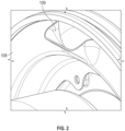
FIG. 2 is a front view of a separator plate used in the electric compressor motor ofFIG. 1 , in accordance with an embodiment; -
FIG. 3 is a front view of a motor cooling outlet of a motor cooling outlet structure electric compressor motor ofFIG. 1 , in accordance with an embodiment; and -
FIG. 4 is an operational block diagram illustrating a method for increasing stator cooling airflow in an electric compressor motor is shown, in accordance with an embodiment. - A detailed description of one or more embodiments of the disclosed apparatus and method are presented herein by way of exemplification and not limitation with reference to the several Figures. In accordance with an embodiment, the present invention provides a separator plate for use with an air cooled electric motor of an ECS compressor to utilize compressor seal leakage and bearing cooling flow as a second airflow stream, wherein the second airflow stream is injected into the motor cooling outlet port at a higher velocity than the base cooling flow to increase the overall cooling flow. The momentum from the second airflow stream 'pulls' air through the motor stator thereby increasing the total stator cooling mass airflow. Essentially, the method 'utilizes' a weak ejector effect to create a low pressure area around the stator heat exchanger exit. It should be appreciated that the method and design of the invention, increases the stator cooling airflow while having no negative impact on the performance of the CAC and/or the aircraft ECS. As such, the invention accomplishes an increased stator cooling airflow using a low weight design that will have no negative impact on the CAC aircraft interface and the CAC air supply to the aircraft, and that does not increase CAC power consumption. In an embodiment, the invention may provide an increase in motor airflow of about 10% over current methods while separating the higher temperature seal leakage airflow from the motor stator plenum (i.e., stator outlet cavity).
- Referring to
FIG. 1 ,FIG. 2 andFIG. 3 , a sectional view of an air cooledelectric motor 100 and amotor cooling housing 200 is shown, in accordance with an embodiment. The air cooledelectric motor 100 includes acompressor outlet housing 102 which includes acompressor seal 104, a motorcavity separator wall 106 and aseparator plate 108 which defines aseparator plate opening 109. Thecompressor outlet housing 102 defines aseparator plate cavity 110 and a compressor rotor back-face cavity 112. The motorcavity separator wall 106 is disposed to separate theseparator plate cavity 110 from the compressor rotor back-face cavity 112, wherein the motorcavity separator wall 106 defines one or more motor cavity separator wall through-holes 114 which communicate theseparator plate cavity 110 with the compressor rotor back-face cavity 112. It should be appreciated that the motorcavity separator wall 106 also separates the bearing cooling and seal leakage flow from the stator outlet flow. Theseparator plate 108 further separates this flow from the stator outlet flow until it is far enough downstream that it no longer inhibits the stator cooling flow. Theseparator plate 108 also introduces the ejector effect, referenced hereinabove, to create a low pressure area around the statorheat exchanger exit 115. - The one or more motor cavity separator wall through-
holes 114 allow the airflow to travel between the compressor rotor back-face cavity 112 and theseparator plate cavity 110. Themotor cooling housing 200 includes a motorcooling outlet structure 202 which defines a motor coolingoutlet structure inlet 204, amotor cooling outlet 206, a stator motorcooling flow path 208 and astator outlet cavity 210, wherein thestator outlet cavity 210 communicates the stator motorcooling flow path 208 with the motor coolingoutlet structure inlet 204. Theseparator plate 108 is disposed to separate thestator outlet cavity 210 from theseparator plate cavity 110 and also acts to direct the stator motorcooling flow path 208 into the motor coolingoutlet structure inlet 204. - Accordingly, the invention allows for the compressor
seal leakage airflow 300 and thebearing cooling airflow 302 to be combined within the compressor bearing back-face cavity 112 before flowing through the one or more motor cavity separator wall through-holes 114, into theseparator plate cavity 110 and injected into thestator outlet cavity 210 via theseparator plate opening 109 which communicates theseparator plate cavity 110 with thestator outlet cavity 210. Once in thestator outlet cavity 210, the airflow is further combined with the stator motor cooling airflow that is flowing into thestator outlet cavity 210 from the stator motorcooling flow path 208. The combination airflow is then pulled into the motor coolingoutlet structure inlet 204 and out of themotor cooling outlet 206. - It should be appreciated that the separator plate opening 109 should be sized such that the total cross-sectional area of the separator plate opening 109 is less than or equal to the total cross-sectional area of the one or more separator wall through-
holes 114. This keeps the pressure within theseparator plate cavity 110 higher than the pressure within thestator outlet cavity 210 to drive a higher exit velocity of the airflow out of theseparator plate opening 109 and into thestator outlet cavity 210 thereby increasing the ejector effect. By controlling the size of the cavity openings (i.e.,separator plate opening 109, motor cavity separator wall through-holes 114, etc.) the pressure control and airflow rate velocity may be controlled. Moreover, in an embodiment, the shape of theseparator plate opening 109 and/or the positioning of the one or more motor cavity separator wall through-holes 114 may also be configured to improve the performance of the ejector effect. It should be appreciated that the size and number of separator wall through-holes 114 and the size of the separator plate opening 109 may be different for each application. The size and number of separator wall through-holes 114 may be determined through an iterative process that defines the total cross sectional area as a function of inlet flow rates and cavity pressures with considerations being made for aerodynamic thrust loads and the structural capabilities of the assembly. Similarly, the size of the separator plate opening 109 may be determined through an iterative process that defines the total cross sectional area as a function of inlet flow rates, cavity pressures, and desired flow velocities. - Referring to
FIG. 4 , an operational block diagram illustrating amethod 400 for increasing stator cooling airflow in an air cooledelectric motor 100 is shown, in accordance with an embodiment. Themethod 400 includes separating thestator outlet cavity 210 from the compressor rotor back-face cavity 112 via a motorcavity separator wall 106, as shown inoperational block 402, wherein the motorcavity separator wall 106 defines one or more motor cavity separator wall through-holes 114. Aseparator plate 108 is securely disposed proximate the motorcavity separator wall 106 to separate the motorcavity separator wall 106 from thestator outlet cavity 210 and to create aseparator plate cavity 110 between theseparator plate 108 and the motorcavity separator wall 106, as shown inoperational block 404. Theseparator plate 108 defines a separator plate opening 109 which communicates theseparator plate cavity 110 with thestator outlet cavity 210 and the motor coolingoutlet structure inlet 204. The compressor rotor back-face cavity 112 is in flow communication with theseparator plate cavity 110 via the one or more motor cavity separator wall through-holes 114, and theseparator plate cavity 110 is in flow communication with thestator outlet cavity 210 via theseparator plate opening 109. - Moreover, as discussed above, the separator plate opening 109 should be sized such that the total cross-sectional area of the separator plate opening 109 is less than or equal to the total cross-sectional area of the one or more motor cavity separator wall through-
holes 114. It should be appreciated that the invention allows the compressorseal leakage airflow 300 and the bearingcooling airflow 302 to be combined in the compressor rotor back-face cavity 112, communicated to theseparator plate cavity 110 via the one or more motor cavity separator wall through-holes 114 and communicated into thestator outlet cavity 210 via theseparator plate opening 109, wherein the velocity of air exiting themotor cooling outlet 206 creates a lower pressure region behind the stator which increases the stator Outer Diameter (OD) airflow. - The term "about" is intended to include the degree of error associated with measurement of the particular quantity based upon the equipment available at the time of filing the application.
- The terminology used herein is for the purpose of describing particular embodiments only and is not intended to be limiting of the present disclosure. As used herein, the singular forms "a", "an" and "the" are intended to include the plural forms as well, unless the context clearly indicates otherwise. It will be further understood that the terms "comprises" and/or "comprising," when used in this specification, specify the presence of stated features, integers, steps, operations, elements, and/or components, but do not preclude the presence or addition of one or more other features, integers, steps, operations, element components, and/or groups thereof.
- While the present disclosure has been described with reference to an exemplary embodiment or embodiments, it will be understood by those skilled in the art that various changes may be made and equivalents may be substituted for elements thereof without departing from the scope of the present disclosure. Moreover, the embodiments or parts of the embodiments may be combined in whole or in part without departing from the scope of the invention. In addition, many modifications may be made to adapt a particular situation or material to the teachings of the present disclosure without departing from the essential scope thereof. Therefore, it is intended that the present disclosure not be limited to the particular embodiment disclosed as the best mode contemplated for carrying out this disclosure, but that the present disclosure will include all embodiments falling within the scope of the claims.
Claims (15)
- An air cooled electric motor, comprising:a compressor outlet housing, wherein the compressor outlet housing includes a motor cavity separator wall and a separator plate defining a separator plate opening and a separator plate cavity,wherein the compressor outlet housing defines a compressor rotor back-face cavity configured to receive a back-face cavity airflow, andwherein the motor cavity separator wall separates the separator plate cavity from the compressor rotor back-face cavity and defines at least one motor cavity separator wall through-hole which communicates the compressor rotor back-face cavity with the separator plate cavity; anda motor cooling housing including a motor cooling outlet structure which defines a motor cooling outlet structure inlet, a motor cooling outlet, a stator motor cooling flow path and a stator outlet cavity, wherein the stator outlet cavity communicates the stator motor cooling flow path with the motor cooling outlet structure inlet, andwherein the separator plate is disposed to separate the stator outlet cavity from the separator plate cavity, and wherein the separator plate opening is configured to allow the back-face cavity airflow to flow into the stator outlet cavity and into the motor cooling outlet structure inlet.
- The air cooled electric motor of claim 1, wherein the at least one motor cavity separator wall through-hole includes a plurality of motor cavity separator wall through-holes.
- The air cooled electric motor of claim 1 or 2, wherein the separator plate is disposed to create a high pressure area within the separator plate cavity and a low pressure area proximate the stator outlet cavity.
- The air cooled electric motor of claim 1, 2 or 3, where the compressor rotor back-face cavity is communicated with a compressor seal to receive a motor seal airflow leakage.
- The air cooled electric motor of claim 4, wherein the compressor rotor back-face cavity is further communicated with a bearing cooling airflow path to receive a bearing cooling airflow.
- The air cooled electric motor of claim 5, wherein the compressor rotor back-face cavity is configured to combine the motor seal airflow leakage and the bearing cooling airflow to create the back-face cavity airflow.
- The air cooled electric motor of any preceding claim, wherein the at least one motor cavity separator wall through-hole includes a motor cavity separator wall through-hole total cross-sectional area, and wherein the separator plate opening includes a separator plate opening total cross-sectional area.
- The air cooled electric motor of claim 7, wherein the separator plate opening total cross-sectional area is less than or equal to the motor cavity separator wall through-hole total cross-sectional area.
- An air cooled electric motor, comprising:a compressor outlet housing, wherein the compressor outlet housing includes a motor cavity separator wall and a separator plate defining a separator plate cavity and a separator plate opening having a separator plate opening cross-sectional area,wherein the compressor outlet housing defines a compressor rotor back-face cavity configured to receive a back-face cavity airflow, andwherein the motor cavity separator wall separates the separator plate cavity from the compressor rotor back-face cavity and defines a motor cavity separator wall through-hole which communicates the compressor rotor back-face cavity with the separator plate cavity, wherein the motor cavity separator wall through-hole includes a motor cavity separator wall through-hole cross-sectional area, wherein the separator plate opening cross-sectional area is less than or equal to the motor cavity separator wall through-hole cross-sectional area; anda motor cooling housing including a motor cooling outlet structure which defines a stator outlet cavity, wherein the separator plate is disposed to separate the stator outlet cavity from the separator plate cavity.
- The air cooled electric motor of claim 9, wherein the separator plate opening is configured to allow the back-face cavity airflow to flow into the stator outlet cavity; and/orwherein the motor cavity separator wall through-hole includes a plurality of motor cavity separator wall through-holes; and/orwherein the separator plate is disposed to create a high pressure area within the separator plate cavity and a low pressure area proximate the stator outlet cavity.
- The air cooled electric motor of claim 9 or 10, wherein the compressor rotor back-face cavity is communicated with a compressor seal to receive a motor seal airflow leakage.
- The air cooled electric motor of claim 11, wherein the compressor rotor back-face cavity is further communicated with a bearing cooling airflow path to receive a bearing cooling airflow, optionally wherein the compressor rotor back-face cavity is configured to combine the motor seal airflow leakage and the bearing cooling airflow to create the back-face cavity airflow.
- The air cooled electric motor of any of claims 9 to 12, wherein the motor cooling outlet structure includes a motor cooling outlet, and wherein the stator outlet cavity communicates a stator motor cooling flow path with the motor cooling outlet.
- A method for increasing stator cooling airflow in an air cooled electric motor having a compressor outlet housing and a motor cooling housing, wherein the compressor outlet housing includes a motor cavity separator wall and defines a separator plate cavity and a compressor rotor back-face cavity and wherein the motor cooling housing defines a motor cooling outlet and includes a stator outlet cavity, the method comprising:separating the stator outlet cavity from the compressor rotor back-face cavity via the motor cavity separator wall, wherein the motor cavity separator wall defines one or more motor cavity separator wall through-holes which communicate the compressor rotor back-face cavity with the separator plate cavity; anddisposing the separator plate between the motor cavity separator wall and the stator outlet cavity to enclose the separator plate cavity located between the separator plate and the motor cavity separator wall, wherein the separator plate defines a separator plate opening which communicates the separator plate cavity with the stator outlet cavity.
- The method of claim 14,wherein the compressor rotor back-face cavity is configured to receive a compressor seal airflow leakage and a bearing cooling airflow, andwherein the compressor seal airflow leakage and the bearing cooling airflow are combined within the compressor rotor back-face cavity to create a back-face cavity airflow; and/orwherein the separator plate opening includes a separator plate opening cross sectional area and the one or more motor cavity separator wall through-hole includes a motor cavity separator wall through-hole cross-sectional area, andwherein the separator plate opening cross sectional area is less than or equal to the motor cavity separator wall through-hole cross-sectional area; and/orwherein the separator plate is disposed to create a high pressure area within the separator plate cavity and a low pressure area proximate the stator outlet cavity.
Applications Claiming Priority (1)
| Application Number | Priority Date | Filing Date | Title |
|---|---|---|---|
| US18/239,639 US12531454B2 (en) | 2023-08-29 | 2023-08-29 | Air cooled electric motor having an increased airflow and a method for increasing the airflow therein |
Publications (1)
| Publication Number | Publication Date |
|---|---|
| EP4518113A1 true EP4518113A1 (en) | 2025-03-05 |
Family
ID=92593355
Family Applications (1)
| Application Number | Title | Priority Date | Filing Date |
|---|---|---|---|
| EP24197092.0A Pending EP4518113A1 (en) | 2023-08-29 | 2024-08-28 | An air cooled electric motor having an increased airflow and a method for increasing the airflow therein |
Country Status (2)
| Country | Link |
|---|---|
| US (1) | US12531454B2 (en) |
| EP (1) | EP4518113A1 (en) |
Citations (5)
| Publication number | Priority date | Publication date | Assignee | Title |
|---|---|---|---|---|
| US20140357176A1 (en) * | 2013-05-28 | 2014-12-04 | Hamilton Sundstrand Corporation | Motor cooling blower and containment structure |
| US20160218590A1 (en) * | 2013-09-03 | 2016-07-28 | Nuovo Pignone Srl | Fancooled electrical machine with axial thrust compensation |
| EP3173336A1 (en) * | 2015-11-25 | 2017-05-31 | Hamilton Sundstrand Corporation | Supply tube for sensor |
| WO2020052011A1 (en) * | 2018-09-10 | 2020-03-19 | 石家庄金士顿轴承科技有限公司 | High-speed motor cooling mechanism for fuel cell air compressor |
| US11365742B2 (en) * | 2015-12-21 | 2022-06-21 | Hamilton Sundstrand Corporation | Thermal enhancement of cabin air compressor motor cooling |
Family Cites Families (7)
| Publication number | Priority date | Publication date | Assignee | Title |
|---|---|---|---|---|
| US7302804B2 (en) | 2003-06-24 | 2007-12-04 | Honeywell International, Inc. | Cabin air compressor cooling system |
| US20060067833A1 (en) * | 2004-09-22 | 2006-03-30 | Hamilton Sundstrand | Integral add heat and surge control valve for compressor |
| US8863548B2 (en) * | 2010-07-16 | 2014-10-21 | Hamilton Sundstrand Corporation | Cabin air compressor motor cooling |
| US9243643B2 (en) * | 2012-07-27 | 2016-01-26 | Hamilton Sundstrand Corporation | Cabin air compressor housing |
| US11261880B2 (en) | 2019-08-02 | 2022-03-01 | Hamilton Sundstrand Corporation | Motor and bearing cooling paths |
| US11143203B2 (en) | 2019-08-02 | 2021-10-12 | Hamilton Sundstrand Corporation | Motor and bearing cooling paths |
| US11530705B2 (en) | 2020-11-17 | 2022-12-20 | Hamilton Sundstrand Corporation | Bearing cooling schemes for aircraft fans |
-
2023
- 2023-08-29 US US18/239,639 patent/US12531454B2/en active Active
-
2024
- 2024-08-28 EP EP24197092.0A patent/EP4518113A1/en active Pending
Patent Citations (5)
| Publication number | Priority date | Publication date | Assignee | Title |
|---|---|---|---|---|
| US20140357176A1 (en) * | 2013-05-28 | 2014-12-04 | Hamilton Sundstrand Corporation | Motor cooling blower and containment structure |
| US20160218590A1 (en) * | 2013-09-03 | 2016-07-28 | Nuovo Pignone Srl | Fancooled electrical machine with axial thrust compensation |
| EP3173336A1 (en) * | 2015-11-25 | 2017-05-31 | Hamilton Sundstrand Corporation | Supply tube for sensor |
| US11365742B2 (en) * | 2015-12-21 | 2022-06-21 | Hamilton Sundstrand Corporation | Thermal enhancement of cabin air compressor motor cooling |
| WO2020052011A1 (en) * | 2018-09-10 | 2020-03-19 | 石家庄金士顿轴承科技有限公司 | High-speed motor cooling mechanism for fuel cell air compressor |
Also Published As
| Publication number | Publication date |
|---|---|
| US20250079930A1 (en) | 2025-03-06 |
| US12531454B2 (en) | 2026-01-20 |
Similar Documents
| Publication | Publication Date | Title |
|---|---|---|
| CN114144355B (en) | Electric Aircraft Propulsion Systems | |
| US11655043B2 (en) | Electric aircraft propulsion system | |
| US11159074B1 (en) | Cooling motor controller with a motor including wedge-shaped heat sinks | |
| EP3667875B1 (en) | Motor cooling system and method | |
| US6058715A (en) | Environmental control system including air cycle machine and electrical machine | |
| EP2407380B1 (en) | Cabin air compressor motor cooling | |
| US7302804B2 (en) | Cabin air compressor cooling system | |
| US5709103A (en) | Electrically powered differential air-cycle air conditioning machine | |
| EP3626611B1 (en) | Aircraft propulsion system | |
| US11851197B2 (en) | Motor-integrated fan, and vertical takeoff and landing craft | |
| EP3401223A1 (en) | Motor cooling utilizing cabin air | |
| CN112377267B (en) | Self-cooling high-speed ram air turbine generator | |
| EP2808257B1 (en) | Motor cooling blower and containment structure | |
| GB2565886B (en) | Electric engine | |
| US11897618B2 (en) | Cabin air compressor with liquid cooled passage formed in the case | |
| EP3764523B1 (en) | Electric machine with integrated cooling system | |
| CN106930835A (en) | For the method and system that precooler exhaust energy is reclaimed | |
| EP4019785A1 (en) | Cabin air compressor with liquid cooled jacket | |
| US12531454B2 (en) | Air cooled electric motor having an increased airflow and a method for increasing the airflow therein | |
| CN107171494B (en) | A kind of compressed air turbodynamo system | |
| WO2022154059A1 (en) | Fan device and aircraft provided with same | |
| EP3757389B1 (en) | Motor cooling systems | |
| EP4328453A1 (en) | Rotor integrated axial flux electric motor | |
| EP4328454A1 (en) | Rotor integrated axial flux electric motor | |
| CN117627813A (en) | Electric drive type outer stator coil turbine bypass engine and aircraft |
Legal Events
| Date | Code | Title | Description |
|---|---|---|---|
| PUAI | Public reference made under article 153(3) epc to a published international application that has entered the european phase |
Free format text: ORIGINAL CODE: 0009012 |
|
| STAA | Information on the status of an ep patent application or granted ep patent |
Free format text: STATUS: THE APPLICATION HAS BEEN PUBLISHED |
|
| AK | Designated contracting states |
Kind code of ref document: A1 Designated state(s): AL AT BE BG CH CY CZ DE DK EE ES FI FR GB GR HR HU IE IS IT LI LT LU LV MC ME MK MT NL NO PL PT RO RS SE SI SK SM TR |
|
| STAA | Information on the status of an ep patent application or granted ep patent |
Free format text: STATUS: REQUEST FOR EXAMINATION WAS MADE |
|
| 17P | Request for examination filed |
Effective date: 20250904 |
|
| GRAP | Despatch of communication of intention to grant a patent |
Free format text: ORIGINAL CODE: EPIDOSNIGR1 |
|
| STAA | Information on the status of an ep patent application or granted ep patent |
Free format text: STATUS: GRANT OF PATENT IS INTENDED |
|
| INTG | Intention to grant announced |
Effective date: 20260331 |
|
| RIC1 | Information provided on ipc code assigned before grant |
Ipc: H02K 9/06 20060101AFI20260326BHEP Ipc: H02K 5/20 20060101ALI20260326BHEP Ipc: H02K 7/14 20060101ALI20260326BHEP Ipc: H02K 5/16 20060101ALI20260326BHEP Ipc: F04D 29/58 20060101ALI20260326BHEP Ipc: F04D 25/06 20060101ALI20260326BHEP Ipc: H02K 1/20 20060101ALN20260326BHEP Ipc: H02K 9/16 20060101ALN20260326BHEP Ipc: B64D 13/06 20060101ALN20260326BHEP Ipc: F04F 5/16 20060101ALN20260326BHEP |