EP4518065A1 - Charger and control method of the same - Google Patents
Charger and control method of the same Download PDFInfo
- Publication number
- EP4518065A1 EP4518065A1 EP24150027.1A EP24150027A EP4518065A1 EP 4518065 A1 EP4518065 A1 EP 4518065A1 EP 24150027 A EP24150027 A EP 24150027A EP 4518065 A1 EP4518065 A1 EP 4518065A1
- Authority
- EP
- European Patent Office
- Prior art keywords
- guide
- electromagnets
- cable
- guides
- mode
- Prior art date
- Legal status (The legal status is an assumption and is not a legal conclusion. Google has not performed a legal analysis and makes no representation as to the accuracy of the status listed.)
- Withdrawn
Links
Images






Classifications
-
- H—ELECTRICITY
- H02—GENERATION; CONVERSION OR DISTRIBUTION OF ELECTRIC POWER
- H02G—INSTALLATION OF ELECTRIC CABLES OR LINES, OR OF COMBINED OPTICAL AND ELECTRIC CABLES OR LINES
- H02G11/00—Arrangements of electric cables or lines between relatively-movable parts
- H02G11/003—Arrangements of electric cables or lines between relatively-movable parts using gravity-loaded or spring-loaded loop
-
- B—PERFORMING OPERATIONS; TRANSPORTING
- B60—VEHICLES IN GENERAL
- B60L—PROPULSION OF ELECTRICALLY-PROPELLED VEHICLES; SUPPLYING ELECTRIC POWER FOR AUXILIARY EQUIPMENT OF ELECTRICALLY-PROPELLED VEHICLES; ELECTRODYNAMIC BRAKE SYSTEMS FOR VEHICLES IN GENERAL; MAGNETIC SUSPENSION OR LEVITATION FOR VEHICLES; MONITORING OPERATING VARIABLES OF ELECTRICALLY-PROPELLED VEHICLES; ELECTRIC SAFETY DEVICES FOR ELECTRICALLY-PROPELLED VEHICLES
- B60L53/00—Methods of charging batteries, specially adapted for electric vehicles; Charging stations or on-board charging equipment therefor; Exchange of energy storage elements in electric vehicles
- B60L53/30—Constructional details of charging stations
- B60L53/35—Means for automatic or assisted adjustment of the relative position of charging devices and vehicles
-
- B—PERFORMING OPERATIONS; TRANSPORTING
- B60—VEHICLES IN GENERAL
- B60L—PROPULSION OF ELECTRICALLY-PROPELLED VEHICLES; SUPPLYING ELECTRIC POWER FOR AUXILIARY EQUIPMENT OF ELECTRICALLY-PROPELLED VEHICLES; ELECTRODYNAMIC BRAKE SYSTEMS FOR VEHICLES IN GENERAL; MAGNETIC SUSPENSION OR LEVITATION FOR VEHICLES; MONITORING OPERATING VARIABLES OF ELECTRICALLY-PROPELLED VEHICLES; ELECTRIC SAFETY DEVICES FOR ELECTRICALLY-PROPELLED VEHICLES
- B60L53/00—Methods of charging batteries, specially adapted for electric vehicles; Charging stations or on-board charging equipment therefor; Exchange of energy storage elements in electric vehicles
- B60L53/10—Methods of charging batteries, specially adapted for electric vehicles; Charging stations or on-board charging equipment therefor; Exchange of energy storage elements in electric vehicles characterised by the energy transfer between the charging station and the vehicle
- B60L53/14—Conductive energy transfer
- B60L53/16—Connectors, e.g. plugs or sockets, specially adapted for charging electric vehicles
-
- B—PERFORMING OPERATIONS; TRANSPORTING
- B60—VEHICLES IN GENERAL
- B60L—PROPULSION OF ELECTRICALLY-PROPELLED VEHICLES; SUPPLYING ELECTRIC POWER FOR AUXILIARY EQUIPMENT OF ELECTRICALLY-PROPELLED VEHICLES; ELECTRODYNAMIC BRAKE SYSTEMS FOR VEHICLES IN GENERAL; MAGNETIC SUSPENSION OR LEVITATION FOR VEHICLES; MONITORING OPERATING VARIABLES OF ELECTRICALLY-PROPELLED VEHICLES; ELECTRIC SAFETY DEVICES FOR ELECTRICALLY-PROPELLED VEHICLES
- B60L53/00—Methods of charging batteries, specially adapted for electric vehicles; Charging stations or on-board charging equipment therefor; Exchange of energy storage elements in electric vehicles
- B60L53/10—Methods of charging batteries, specially adapted for electric vehicles; Charging stations or on-board charging equipment therefor; Exchange of energy storage elements in electric vehicles characterised by the energy transfer between the charging station and the vehicle
- B60L53/14—Conductive energy transfer
- B60L53/18—Cables specially adapted for charging electric vehicles
-
- B—PERFORMING OPERATIONS; TRANSPORTING
- B60—VEHICLES IN GENERAL
- B60L—PROPULSION OF ELECTRICALLY-PROPELLED VEHICLES; SUPPLYING ELECTRIC POWER FOR AUXILIARY EQUIPMENT OF ELECTRICALLY-PROPELLED VEHICLES; ELECTRODYNAMIC BRAKE SYSTEMS FOR VEHICLES IN GENERAL; MAGNETIC SUSPENSION OR LEVITATION FOR VEHICLES; MONITORING OPERATING VARIABLES OF ELECTRICALLY-PROPELLED VEHICLES; ELECTRIC SAFETY DEVICES FOR ELECTRICALLY-PROPELLED VEHICLES
- B60L53/00—Methods of charging batteries, specially adapted for electric vehicles; Charging stations or on-board charging equipment therefor; Exchange of energy storage elements in electric vehicles
- B60L53/30—Constructional details of charging stations
- B60L53/305—Communication interfaces
-
- B—PERFORMING OPERATIONS; TRANSPORTING
- B60—VEHICLES IN GENERAL
- B60L—PROPULSION OF ELECTRICALLY-PROPELLED VEHICLES; SUPPLYING ELECTRIC POWER FOR AUXILIARY EQUIPMENT OF ELECTRICALLY-PROPELLED VEHICLES; ELECTRODYNAMIC BRAKE SYSTEMS FOR VEHICLES IN GENERAL; MAGNETIC SUSPENSION OR LEVITATION FOR VEHICLES; MONITORING OPERATING VARIABLES OF ELECTRICALLY-PROPELLED VEHICLES; ELECTRIC SAFETY DEVICES FOR ELECTRICALLY-PROPELLED VEHICLES
- B60L53/00—Methods of charging batteries, specially adapted for electric vehicles; Charging stations or on-board charging equipment therefor; Exchange of energy storage elements in electric vehicles
- B60L53/30—Constructional details of charging stations
- B60L53/31—Charging columns specially adapted for electric vehicles
-
- H—ELECTRICITY
- H02—GENERATION; CONVERSION OR DISTRIBUTION OF ELECTRIC POWER
- H02J—ELECTRIC POWER NETWORKS; CIRCUIT ARRANGEMENTS OR SYSTEMS FOR SUPPLYING OR DISTRIBUTING ELECTRIC POWER; SYSTEMS FOR STORING ELECTRIC ENERGY
- H02J7/00—Circuit arrangements for charging or discharging batteries or for supplying loads from batteries
- H02J7/70—Circuit arrangements for charging or discharging batteries or for supplying loads from batteries characterised by the mechanical construction
-
- B—PERFORMING OPERATIONS; TRANSPORTING
- B60—VEHICLES IN GENERAL
- B60Y—INDEXING SCHEME RELATING TO ASPECTS CROSS-CUTTING VEHICLE TECHNOLOGY
- B60Y2200/00—Type of vehicle
- B60Y2200/90—Vehicles comprising electric prime movers
- B60Y2200/91—Electric vehicles
-
- B—PERFORMING OPERATIONS; TRANSPORTING
- B60—VEHICLES IN GENERAL
- B60Y—INDEXING SCHEME RELATING TO ASPECTS CROSS-CUTTING VEHICLE TECHNOLOGY
- B60Y2300/00—Purposes or special features of road vehicle drive control systems
- B60Y2300/91—Battery charging
-
- Y—GENERAL TAGGING OF NEW TECHNOLOGICAL DEVELOPMENTS; GENERAL TAGGING OF CROSS-SECTIONAL TECHNOLOGIES SPANNING OVER SEVERAL SECTIONS OF THE IPC; TECHNICAL SUBJECTS COVERED BY FORMER USPC CROSS-REFERENCE ART COLLECTIONS [XRACs] AND DIGESTS
- Y02—TECHNOLOGIES OR APPLICATIONS FOR MITIGATION OR ADAPTATION AGAINST CLIMATE CHANGE
- Y02T—CLIMATE CHANGE MITIGATION TECHNOLOGIES RELATED TO TRANSPORTATION
- Y02T10/00—Road transport of goods or passengers
- Y02T10/60—Other road transportation technologies with climate change mitigation effect
- Y02T10/70—Energy storage systems for electromobility, e.g. batteries
-
- Y—GENERAL TAGGING OF NEW TECHNOLOGICAL DEVELOPMENTS; GENERAL TAGGING OF CROSS-SECTIONAL TECHNOLOGIES SPANNING OVER SEVERAL SECTIONS OF THE IPC; TECHNICAL SUBJECTS COVERED BY FORMER USPC CROSS-REFERENCE ART COLLECTIONS [XRACs] AND DIGESTS
- Y02—TECHNOLOGIES OR APPLICATIONS FOR MITIGATION OR ADAPTATION AGAINST CLIMATE CHANGE
- Y02T—CLIMATE CHANGE MITIGATION TECHNOLOGIES RELATED TO TRANSPORTATION
- Y02T10/00—Road transport of goods or passengers
- Y02T10/60—Other road transportation technologies with climate change mitigation effect
- Y02T10/7072—Electromobility specific charging systems or methods for batteries, ultracapacitors, supercapacitors or double-layer capacitors
-
- Y—GENERAL TAGGING OF NEW TECHNOLOGICAL DEVELOPMENTS; GENERAL TAGGING OF CROSS-SECTIONAL TECHNOLOGIES SPANNING OVER SEVERAL SECTIONS OF THE IPC; TECHNICAL SUBJECTS COVERED BY FORMER USPC CROSS-REFERENCE ART COLLECTIONS [XRACs] AND DIGESTS
- Y02—TECHNOLOGIES OR APPLICATIONS FOR MITIGATION OR ADAPTATION AGAINST CLIMATE CHANGE
- Y02T—CLIMATE CHANGE MITIGATION TECHNOLOGIES RELATED TO TRANSPORTATION
- Y02T90/00—Enabling technologies or technologies with a potential or indirect contribution to GHG emissions mitigation
- Y02T90/10—Technologies relating to charging of electric vehicles
- Y02T90/12—Electric charging stations
Definitions
- the present invention relates to a charger and a control method of the same
- a charger is a device used to charge a storage battery.
- An example of the charger may be an electric vehicle charger that charges a vehicle such as an electric vehicle, and electrical energy is supplied to a battery of the electric vehicle by connecting a charging connector provided at an end of a charging cable to a connection inlet installed in the electric vehicle.
- the charging cable When not in use, the charging cable may be wound or coiled, and the charging cable may be used after unwinding the coiled charging cable and withdrawing the charging cable from a dock or holder. Due to a length of a pulled-out or withdrawn charging cable, a middle portion of the charging cable may touch a floor or ground, and the portion touching the floor or ground may be damaged by repeated use, such as by being worn out or contaminated by contact with contaminants on the floor.
- the charging device for an electric vehicle comprises a charging body; a charging cable connected to the charging body and having a charging gun, connector or coupler at an end; a guide frame installed on one side of the charging body and on which a rail guide is formed; first and second roller modules formed to travel along the rail guide of the guide frame; and a mounting bracket that is connected to the first and second roller modules and transported together, and the first and second roller modules travel on the rail guide according to the stopping position of the electric vehicle that needs to be charged, and can move the position of the charging cable.
- the charging facility for electric vehicles comprises a cable guide unit installed on the ceiling of the car deck where electric vehicles are loaded; a vehicle charging device that charges the driving battery of the electric vehicle while moving back and forth along the cable guide; and a power management device that supplies power to the driving battery.
- the cable guide part comprises a rail that provides a path along which the running part of the vehicle charging device moves and installed on the ceiling in the length direction of the car deck on which the electric vehicle is arranged in a straight line; and a plurality of guide rings installed to slide along the rail and configured to allow the charging cable of the vehicle charging device to be suspended at regular intervals.
- the vehicle charging device comprises a charging cable having one end connected to the power management device and a plug at the other end to charge the driving battery; and a traveling part that is movably installed on the cable guide part and moves the charging cable.
- a purpose of this embodiment is to provide a charger and a control method of the same that can minimize the force with which the user pulls the charging cable.
- a purpose of this embodiment is to provide a charger and a control method of the same through which a charging cable can be reliably pull in.
- a charger comprises a rail body on which a plurality of rails is formed; a plurality of guides that are slidably arranged on each of the plurality of rails and on which the charging cable is suspended; a plurality of electromagnets disposed on each of the plurality of guides; and a control unit configured to control the plurality of electromagnets.
- the control unit may be configured to control a position of the charging cable by controlling the plurality of electromagnets.
- Each of the plurality of guides may comprise an overlap area that overlaps another adjacent guide in the longitudinal direction of the guide and a non-overlap area that does not overlap another adjacent guide in the longitudinal direction of the guide.
- a first guide of the plurality of guides may be disposed such that an overlap area of the first guide overlaps an overlap area of an adjacent second guide with respect to a longitudinal direction of the rail body.
- the guide may comprise a base.
- a supporter may be formed on a bottom of the base and on which the charging cable is suspended.
- the overlap area may be formed in the base, and supporters of the plurality of guides may not overlap.
- the charger may further comprise a guide communication module disposed in the guide.
- a receiving portion in which the guide communication module is accommodated may be formed inside the guide.
- the charger may further comprise a flat cable disposed between the rail body and the guide and configured to supply power to the plurality of electromagnets.
- the charger may further comprise at least one ball disposed on an upper surface of the guide.
- the ball may be in contact with the flat cable.
- the at least one ball may be disposed between the upper surface of the guide and the flat cable.
- the control unit may be configured to perform a pull-out mode in which the control unit is configured to control a plurality of electromagnets such that the plurality of guides moves away from each other.
- the charger may comprise a main body to which a charging cable is connected.
- the main body may comprise a holster on which a coupler of the charging cable is mounted.
- a coupler sensor may be installed in the holster to detect the coupler.
- the main body may further comprise a coupler holder rotatably or slidably disposed in the holster.
- the pull-out mode may be initiated when the coupler sensor detects pulling out of the coupler.
- the charger may comprise a coupler holder rotatably or slidably disposed in the holster.
- the pull-out mode may comprise a first mode in which the control unit is configured to turn on a first electromagnet and a second electromagnet among the plurality of electromagnets with the same polarity. It may further comprise a second mode in which the control unit is configured to turn on the first and second electromagnets among the plurality of electromagnets with opposite polarities after the first mode.
- the control unit may be configured to turn on the second and the third electromagnets among the plurality of electromagnets with the same polarity during the second mode.
- the pull-out mode may further comprise a third mode in which the control unit is configured to turn on the first and second electromagnets among the plurality of electromagnets to the same polarity after the second mode.
- the control unit may be configured to turn on the second and the third electromagnets among the plurality of electromagnets with the same polarity during third mode.
- the control unit may be configured to perform a pull-in mode in which a plurality of electromagnets is controlled so that the plurality of guides is moved closer to each other.
- the pull-in mode may be initiated when the charging cable is disconnected from the electric vehicle.
- the control unit may be configured to perform a locking mode that controls the plurality of electromagnets to keep the plurality of guides close to each other.
- the control unit may be configured to generate a cable-out signal that controls a plurality of electromagnets so that the plurality of guides moves away from each other, if the coupler of the charging cable is separated from the main body. It may further be configured to generate a first cable stop signal, if the coupler of the charging cable is connected to an electric vehicle. It may further be configured to generate a cable-in signal that controls a plurality of electromagnets so that the plurality of guides are moved closer to each other, if the coupler of the charging cable is separated from the electric vehicle. It may further be configured to generate a second cable stop signal, if the coupler of the charging cable is mounted on the main body.
- a control method of the charger comprises generating a cable-out signal that controls a plurality of electromagnets so that the plurality of guides moves away from each other, if the coupler of the charging cable is separated from a main body; generating a first cable stop signal if the coupler of the charging cable is connected to an electric vehicle; generating a cable-in signal to control a plurality of electromagnets so that the plurality of guides are moved closer to each other, if the coupler of the charging cable is separated from the electric vehicle; and generating a second cable stop signal, if the coupler of the charging cable is mounted on the main body.
- FIG. 1 is a perspective view showing a charger when a charging cable according to an embodiment is pulled in;
- FIG. 2 is a perspective view showing the charger when the charging cable according to an embodiment is pulled out,
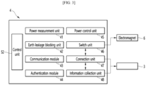
- FIG. 3 is a view showing the configuration of the main body according to an embodiment, and
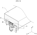
- FIG. 4 is a view of a holster provided in the main body according to an embodiment.
- the charger may be a charging station that charges an electric vehicle.
- the charger may comprise a rail body 1, a plurality of guides 2, a charging cable 3, and a main body 4.
- the rail body 1 may be placed on the main body 4 or placed close to the main body 4.
- the rail body 1 may be placed on a pair of posts 11 and 12 spaced apart from each other.
- the rail body 1 may be elongated along the front and rear direction X as shown in Fig. 2 .
- a rail on which the guide 2 slides may be formed on the rail body 1.
- a plurality of guides 2 can slide along the rail body 1.
- a plurality of guides 2 may be disposed on the rail body 1 to slide independently of each other.
- the plurality of guides 2 may be spaced apart from each other in the longitudinal direction X of the rail body 1.
- Each of the plurality of guides 2 may be a non-magnetic material.
- Each of the plurality of guides 2 may be a non-conductor.
- a plurality of guides 2 may be arranged in a row on the rail body 1.
- a plurality of guides 2 may be disposed in a row in the longitudinal direction X of the rail body 1.
- the charging cable 3 may be sequentially mounted on a plurality of guides 2.
- the plurality of guides 2 may be disposed to be spaced apart from each other in the longitudinal direction X of the rail body 1.
- Each of the plurality of guides 2 may have the same or similar component.
- the number of guides 2 may be 2, 3, 4, etc.
- an exemplary embodiment having three guides will be described below, but of course, the number of guides 2 is not limited thereto.
- the guides 2 when explaining a common configuration of the plurality of guides 2, it is referred to as a guide 2, and when explaining a configuration separately, the guides 2 may be referred to as the first guide 21, the second guide 22, and the third guide 23, respectively, for individual description.
- the plurality of guides 2 can distribute the load for mounting the charging cable 3, and the user can pull or push the charging cable 3 with a small force.
- the plurality of guides 2 can move sequentially and can be changed to various positions along the rail body 1.
- the plurality of guides 2 may be gathered as close as possible to the post 11 that is closer to the main body 4 among the pair of posts 11 and 12 and a coupler 31 of the charging cable 3 may be positioned close to the main body 4.
- the charging cable 3 can be defined as being pulled in.
- the plurality of guides 2 may be spaced apart from each other so that the coupler 31 of the charging cable 3 is positioned away from the main body 4, and in this case, the charging cable 3 can be defined as being pulled out.
- the charging cable 3 may extend from the main body 4 and may be suspended on each of a plurality of guides 2. One end of the charging cable 3 may be connected to the connection unit 47 (refer to FIG. 3 ) of the main body 4, and a coupler 31 may be provided on the other end of the charging cable 3.
- An example of the coupler 31 may be a rechargeable/charging gun or coupler that a user can hold.
- the charger may comprise a communication module that is configured to communicate with the electric vehicle being charged by the charging cable 3.
- the communication module may be a power line communication (PLC) module, or the like.
- a communication module may be provided in the coupler 31.
- the communication module placed in the coupler 31 may be configured to receive information related to charging from the electric vehicle.
- the communication module of the coupler 31 can be configured to communicate with the control unit 52.
- the charging cable 3 can be connected to the main body 4.
- the main body 4 may be a charger body, and the main body 4 may comprise a housing or case that forms the exterior of the charger.
- the main body 4 comprises a power measurement unit 41, an earth leakage blocking unit 42, a communication module 43, an authentication module 44, a power control unit 45, a switch unit 46, a connection unit 47, and an information collection unit 48 may be provided.
- the power measurement unit 41 may be configured to measure the power supplied to the electric vehicle through the charging cable 3.
- the earth leakage blocking unit 42 may comprise a circuit that blocks earth leakage in the main body 4 or the charging cable 3.
- the communication module 43 may comprise a module configured to communicate with a mobile terminal or server.
- the authentication module 44 may be configured to authenticate the user using the charger.
- the power control unit 45 may be configured to control the power of the main body 4 or the charging cable 3.
- the switch unit 46 may be electrically connected to a power supply (not shown) provided to the guide 2, and the switch unit 46 may allow current to be applied to or blocked from the power supply provided to the guide 2.
- the power supply may be, e.g., the flat cable 8 as shown in Fig. 8 ).
- the switch unit 46 can allow current to be applied in the opposite direction.
- the switch unit 46 may comprise a first switch capable of blocking the current applied to the power supply unit.
- the switch unit 46 may comprise a second switch capable of switching the current applied to the power supply unit in the opposite direction.
- first switch and the second switch prefferably be provided together in one switch element, and it is also possible for one switch element to apply and block current and change the direction of the current.
- the charging cable 3 may be connected to the connection unit 47.
- the information collection unit 48 may collect and store information on the charging cable 3.
- the information of the charging cable 3 may comprise connection information of the charging cable 3, charging information, suspending information, standby information, or the like.
- the connection information may be information about whether the coupler 31 of the charging cable 3 is connected to or disconnected from the electric vehicle.
- the charging information may comprise information about whether the charging cable 3 is currently charging and information about a charge level of the battery of the electric vehicle.
- the suspending information may comprise information such as whether the coupler 31 of the charging cable 3 is suspended on the holster 50 or separated from the holster 50.
- a screen 49 (as shown in FIGS. 1 and 2 ) may be disposed on the main body 4.
- the user can check charging information through the screen 49 and input charging commands or payment information through the screen 49.
- the main body 4 may comprise a holster 50 on which the coupler 31 of the charging cable 3 is mounted.
- the holster 50 may be a coupler holder or a charging gun holder.
- a coupler sensor 51 that senses the coupler 31 may be installed in the holster 50.
- coupler sensors may be distance sensors or hall sensors or other sensors configured to sense the presence or absence of the coupler 31.
- the coupler sensor 51 is not limited to the above-mentioned types, and of course, any sensor that can sense the presence or absence of the coupler 31 may be applied.
- the coupler sensor 51 is a Hall sensor, a magnet may be installed in the coupler 31, and the coupler sensor 51 may detect a magnetic field when the coupler 31 is completely mounted on the holster 50.
- the coupler sensor 51 may transmit the detection result to the control unit 52.
- the coupler sensor 51 may transmit mounting information to the control unit 52.
- the coupler sensor 51 can transmit an ON signal to the control unit 52.
- the coupler sensor 51 may transmit an OFF signal to the control unit 52.
- the charger may further comprise a control unit 52 that controls the overall operation of the charger.
- the control unit 52 may be installed in the main body 4.
- An example of the control unit 52 may comprise a processor or microcomputer that controls the overall operation of the charger.
- An outlet (not shown) through which the charging cable 3 extends outside the main body 4 may be formed on one side of the main body 4.
- FIG. 5 is a view showing a coupler holder according to an embodiment.
- the charger may comprise a coupler holder 53.
- a groove may be formed in the coupler 31 that may be seated in the coupler holder 53 or configured to receive the coupler holder 53.
- FIG. 5 (a) is a view showing the coupler holder 53 being disposed to protrude inside the holster 50
- FIG. 5 (b) is a view showing an example of the coupler holder being rotated.
- the coupler holder 53 may be placed in the holster 50 to rotate or slide.
- the charger may further comprise a driving source 54 such as a motor capable of rotating the coupler holder 53.
- a driving source 54 such as a motor capable of rotating the coupler holder 53.
- FIG. 6 is a bottom view showing the rail body according to an embodiment
- FIG. 7 is a perspective view of a guide according to an embodiment
- FIG. 8 is a partially cut away (cross sectional) perspective view showing the rail body and guide according to an embodiment.
- the rail body 1 may comprise a beam with a space formed therein, and an opening for forming a rail may be formed in the lower plate of the beam.
- the upper portion of the guide 2 can be movably accommodated in the space of the beam.
- the opening of the beam may be located on the lower side of the space of the beam, and the guide 2 may be moved along the opening in the longitudinal direction of the rail body 1.
- a plurality of rails 13, 14, and 15 may be formed on the rail body 1.
- Each of the plurality of rails 13, 14, and 15 may be formed to be elongated along the longitudinal direction X of the rail body 1.
- the plurality of rails 13, 14, and 15 may be spaced apart from each other in a direction Y perpendicular to the longitudinal direction X of the rail body 1.
- the plurality of guides 2 may be disposed to slide on each of the plurality of rails 13, 14, and 15, respectively.
- the plurality of rails 13, 14, and 15 may correspond to the plurality of guides 2, and the charger may comprise a first guide 21, a second guide 22, and a third guide 23. That is, one rail per guide may be provided.
- the plurality of rails 13, 14, and 15 comprise a first rail 13 on which the first guide 21 is slidably guided, and a second rail 14 on which the second guide 22 is slidably guided, and a third rail 15 on which the third guide 23 is slidably guided.
- the upper plate of each of the plurality of guides 2 may be seated on a rail.
- the plane of each of the plurality of guides 2 may be rectangular, and the length a may be greater than the width b.
- Each of the plurality of guides 2 may comprise an overlap area O and a non-overlap area N.
- the overlap area O may be an area that overlaps a sliding area of another adjacent guide among the guides 2 in the longitudinal direction X of the guide 2.
- the overlap area O may align with another adjacent guide in the longitudinal direction X of the guide 2.
- the overlap area O of the first guide 21 may overlap the second guide 22 in the longitudinal direction X of the first guide 21 and may align with the second guide 22 in the longitudinal direction X of the first guide 21.
- the overlap area O of the second guide 22 may overlap the third guide 23 in the longitudinal direction X of the second guide 22 and may align with the third guide 23 in the longitudinal direction X of the second guide 22.
- the non-overlap area N may be an area that does not overlap with another adjacent guide in the longitudinal direction X of the guide.
- the non-overlap area N of the first guide 21 may not overlap the second guide 22 in the longitudinal direction X of the first guide 21.
- the non-overlap area N of the second guide 22 may not overlap the third guide 23 in the longitudinal direction X of the second guide 22.
- the first guide 21 may comprise a non-overlap area N and an overlap area O.
- the second guide 23 may comprise a pair of overlap areas O and a non-overlap area N located between the pair of overlap areas O.
- One of the pair of overlap areas O may overlap the overlap area O of the first guide 21, and the other of the pair of overlap areas O may overlap the overlap area O of the third guide 23.
- the third guide 23 may comprise an overlap area O and a non-overlap area N.
- each of the plurality of guides 2 comprises an overlap area O and a non-overlap area N, the plurality of guides 2 can move sequentially in the order disposed on the rail body 1, and the entanglement of the charging cable 3 can be minimized.
- An electromagnet 6 (see FIG. 8 ) may be disposed in each of the plurality of guides 2.
- An electromagnet receiving portion 28 in which the electromagnet 6 is accommodated may be formed inside the guide 2.
- the control unit 52 can control a plurality of electromagnets 6.
- the control unit 52 may be configured to control adjacent electromagnets 6 to have the same polarity or the opposite polarity.
- the control unit 52 may be configured to control the switch unit 46 to change adjacent electromagnets 6 to have the same polarity or the opposite polarity.
- Controlling adjacent electromagnets 6 to the same polarity may mean controlling each of the adjacent electromagnets 6 so that the areas facing each other among the adjacent electromagnets 6 have the same polarity (N-N or S-S).
- Controlling adjacent electromagnets 6 to opposite polarities may mean controlling each of the adjacent electromagnets 6 so that the areas facing each other among the adjacent electromagnets 6 have opposite polarities (N-S or S-N).
- the guide 2 may comprise a base 24 and a supporter 26.
- the base 24 may be guided along the rail body 1 in the longitudinal direction X of the rail body 1, and the guide 2 may be a linear moving guide.
- the supporter 26 may support the suspended portion of the charging cable 3.
- the supporter 26 may protrude downward from the bottom of the base 24.
- the supporter 26 may have a ring shape, as shown in FIG. 7 .
- the supporter 26 may have the shape of an open ring or a C-shape.
- the supporter 26 may have an opening 27 through which the charging cable 3 can pass.
- the opening 27 may be opened in a horizontal direction on either the left or right side of the supporter 26.
- the opening 27 may be opened in the left and right direction Y on either the left or right side of the supporter 26.
- the charging cable 3 can be inserted through the opening 27 at the side of the supporter 26 and suspended in the supporter 26.
- the opening directions of the openings 27 of the supporters 26 of the plurality of guides 2 may be alternately opposite to each other.
- the opening 27 formed in the supporter 26 of the first guide 21 is formed on the left side of the supporter 26
- the opening 27 formed in the supporter 26 of the second guide 22 may be formed on the right side of the supporter 26
- the opening 27 formed on the supporter 26 of the third guide 23 may be formed on the left side of the supporter 26.
- the charging cable 3 can be reliably mounted on the plurality of guides 2.
- the supporters 26 of the plurality of guides 2 may be parallel to each other.
- the overlap area O may correspond to an area of the base 24, and the area of the supporters 26 of the plurality of guides 2 may not overlap. In this case, entanglement of the charging cable 3 can be minimized.
- the charger may comprise a guide communication module 7 disposed on the guide 2.
- a communication module receiving portion 29 in which the guide communication module 7 is accommodated may be formed inside the guide 2.
- Examples of the communication module 7 may be a Bluetooth (BT) communication module, an ultra-wideband (UWB) communication module, or the like.
- BT Bluetooth
- UWB ultra-wideband
- a user or an administrator may communicate with the guide communication module 7 through a mobile terminal external to the charger, and the guide communication module 7 may receive signals and other data from the mobile terminal, etc.
- the guide communication module 7 may be configured to communicate with the communication module provided in the coupler 31, and the electromagnet 6 provided in the guide 2 can be turned on or off according to the command received by the guide communication module 7.
- the charger may further comprise a flat cable 8.
- the flat cable 8 may supply power to the electromagnet 6.
- the flat cable 8 may be elongated along the longitudinal direction X of the rail body 1.
- the flat cable 8 may be strip-shaped or plate-shaped.
- the flat cable 8 can be accommodated in the space of the beam.
- the flat cable 8 may be placed between the rail body 1 and the guide 2.
- the flat cable 8 may be placed above or on the upper surface of the guide 2.
- the flat cable 8 may extend horizontally, particularly in the front and rear direction.
- the flat cable 8 can apply current to the electromagnet 6 of the guide 2 in a state its position is fixed to the rail body 1.
- the charger may further comprise bearings, e.g., balls 9.
- the ball 9 may be placed on the upper surface of the guide 2.
- the ball 9 can be brought into contact with the flat cable 8.
- a ball receiving portion 24a in which a portion of the ball 9 is accommodated may be formed on the upper surface of the guide 2.
- the ball 9 can roll when the guide 2 moves.
- a plurality of balls 9 may be placed in the charger, and the guide 2 may slide smoothly on the rail body 1 via the balls 9.
- An example of the guide 2 may be provided with an electrical contact point electrically connected to the electromagnet 6, and the electrical contact point may be in contact with the flat cable 8. Even if the guide 2 slides along the rail body 1, the electrical contact point may remain in contact with the flat cable 8 and apply a current to the electromagnet 6.
- the guide 2 may comprise a wire electrically connected to the electromagnet 6, and the wire may be connected to the flat cable 8. Even if the guide 2 slides along the rail body 1, the wire can remain connected to the flat cable 8, and current can be applied to the electromagnet 6.
- the other example of the guide 2 may comprise a ball 9 electrically connected to the electromagnet 6, and the ball 9 may be in contact with the flat cable 8. Even if the guide 2 slides along the rail body 1, the ball 9 can remain in contact with the flat cable 8 and apply a current to the electromagnet 6.
- FIG. 9 is a view illustrating various modes of the charger according to an embodiment.
- the control unit 52 may be configured to perform a locking mode (refer to (a) of FIG. 9 ).
- the locking mode can be performed in the initial state of the charger.
- control unit 52 may be configured to control the plurality of electromagnets 6 to maintain the plurality of guides 2 to be positioned close to each other, as shown in (a) of FIG. 9 .
- the locking mode may be performed while the coupler 31 is maintained in the holster 50.
- the control unit 52 may be configured to perform a pull-out or withdrawn mode (refer to (b) of FIG. 9 ).
- the pull-out mode may be referred to as a cable-out mode.
- control unit 52 may control the plurality of electromagnets 6 so that the plurality of guides 2 are spaced apart from each other, as shown in (b) of FIG. 9 .
- the pull-out mode may be initiated if the coupler sensor 51 detects separation of the coupler 31 from the holster 50.
- the coupler sensor 51 can detect this and transmit a cable separation signal to the control unit 52. If a cable separation signal is input, the control unit 52 can be configured to control the electromagnets 6 of the two adjacent guides 2 to have the same polarity, and the two adjacent guides 2 can be controlled to be spaced apart from each other.
- the control unit 52 may perform the pull-in or retracting mode (refer to (c) of FIG. 9 ).
- the pull-in mode may be referred to as a cable-in mode.
- control unit 52 may control the plurality of electromagnets 6 so that the plurality of guides 2 are positioned to be closer to each other, as shown in (c) of FIG. 9 .
- the pull-in mode may be initiated if the charging cable 3 is disconnected from the electric vehicle.
- the coupler 31 can communicate with the electric vehicle through PLC communication, or the like, and when the coupler 31 is separated from the electric vehicle, the control unit 52 may be configured to control the electromagnets 6 of the two adjacent guides 2 to have the opposite polarity. This can be done, and the two adjacent guides (2) can be controlled to be moved towards each other or positioned close to each other.
- FIG. 10 is a view showing the pull-out mode of the charger according to an embodiment.
- the electromagnet installed in the first guide 21 will be referred to as 61
- the electromagnet installed in the second guide 22 will be referred to as 62
- the electromagnet installed in the third guide 23 will be referred to as 63.
- the pull-out mode can be performed during the locking mode, i.e., when the charger is in the locking mode (refer to (a) of FIG. 10 ).
- the pull-out mode may include sequentially performing the first mode (refer to (b) of FIG. 10 ), the second mode (refer to (c) of FIG. 10 ), and the third mode (refer to (d) of FIG. 10 ).
- the first mode may be initiated during the locking mode.
- the first electromagnet 61 and the second electromagnet 62 among the plurality of electromagnets 6 may be controlled to have the same polarity, i.e., to be turned on with the same polarity, as shown in (b) of FIG. 10 .
- the first guide 21 and the second guide 22 can move away from each other, as shown in (b) of FIG. 10 .
- control unit 52 may be configured to control, e.g., turn on, the second electromagnet 62 and the third electromagnet 63 to have opposite polarities or may not apply current to the third electromagnet 63.
- the first guide 21 can be moved along the rail body 1, as shown in (b) of FIG. 10 , and the first guide 21 and the second guide 22 may be spaced apart from each other.
- the second mode may be performed after the first mode.
- the first electromagnet 61 and the second electromagnet 62 among the plurality of electromagnets 6 may be controlled to have opposite polarities.
- the first guide 21 and the second guide 22 can be attracted to each other, i.e., moved towards each other, due to an attractive magnetic force between the first and second electromagnets 61, 62.
- control unit 52 may control the second electromagnet 62 and the third electromagnet 63 among the plurality of electromagnets 6 to have the same polarity.
- the second guide 22 can be moved along the rail body 1, as shown in (c) of FIG. 10 , and the second guide 22 and the first guide 21 may be positioned close to each other, and the second guide 22 may be spaced apart from the third guide 23.
- the third mode may be performed after the second mode, and during the third mode, the first electromagnet 61 and the second electromagnet 62 among the plurality of electromagnets 6 may be controlled to have the same polarity.
- the first guide 21 and the second guide 22 can move away from each other.
- the first guide 21 can be moved along the rail body 1, as shown in (d) of FIG. 10 , and the first guide 21 and the second guide 22 may be spaced apart from each other.
- each of the first guide 21, the second guide 22, and the third guide 23 can be spaced apart from other adjacent guides by a set distance or more.
- the pull-out mode may be terminated.
- the pull-in mode may proceed in the reverse order of the pull-out mode and may be initiated in the third mode state.
- the charger can sequentially perform the third mode, the second mode, and the first mode, and the charger can perform the locking mode after the pull-in mode.
- the first, second, and third guides 21, 22, 23 may be positioned as shown in (a) of FIG. 10 .
- the control unit 52 may generate a cable out signal that controls a plurality of electromagnets 61 and 62 so that the plurality of guides 21, 22 and 23 are moved away from each other, if the coupler 31 of the charging cable 3 is separated from the main body 4.
- the plurality of guides 21, 22, and 23 may be moved as shown in FIG. 2 , and the cable 3 connected to the main body 4 may be extended.
- control unit 52 may generate a first cable stop signal if the coupler 31 of the charging cable 3 is connected to the electric vehicle, and movement of the plurality of guides 21, 22, and 23 may be stopped.
- the charging cable 3 may not be extended any further while connected to the main body 4 and the electric vehicle.
- An example of the first cable stop signal may be a signal that turns off the plurality of electromagnets 61, 62, and 63.
- control unit 52 can be configured to generate a cable in signal that controls a plurality of electromagnets 61, 62 (62) so that the plurality of guides 21, 22, and 23 are positioned/moved closer to each other, if the coupler 31 of the charging cable 3 is separated from the electric vehicle.
- the plurality of guides 21, 22, and 23 can be moved as shown in FIG. 1 , and the cable 3 connected to the main body 4 may be pulled as close to the main body (4) as possible.
- control unit 52 may be configured to generate a second cable stop signal, if the coupler 31 of the charging cable 3 is mounted on the main body 4, and movement of the plurality of guides 21, 22, and 23 may be stopped.
- the charging cable 3 can be maintained as close to the main body 4 as possible while connected to the main body 4.
- the second cable stop signal may be the same or different from the first cable stop signal.
- An example of the second cable stop signal may be a signal that turns off the plurality of electromagnets 61, 62, and 63.
- Another example of the second cable stop signal may be a signal that controls a plurality of electromagnets 61, 62, and 63 so that the electromagnets 61, 62, and 63 attract each other.
- the cable out step may be initiated if the coupler 31 of the charging cable 3 is separated from the body 4.
- the control unit 52 may generate a cable out signal to control the plurality of electromagnets 61, 62, and 63 so that the plurality of guides 21, 22, and 23 are positioned/moved to be spaced apart from each other.
- the cable in step can be initiated once the coupler 31 of the charging cable 3 is disconnected from the electric vehicle.
- the control unit 52 may generate a cable-in signal to control the plurality of electromagnets 61, 62, and 63 so that the plurality of guides 21, 22, and 23 are positioned/moved to be closer to each other.
- the guide on which the charging cable is mounted moves along the rail body to gather the charging cable, the force required by the user to return the charging cable can be minimized, and the charging cable can be returned to an original position with high reliability.
- each of the plurality of guides comprises an overlap area, the order of the plurality of guides does not change, and twisting of the charging cable can be minimized.
Landscapes
- Engineering & Computer Science (AREA)
- Power Engineering (AREA)
- Transportation (AREA)
- Mechanical Engineering (AREA)
- Charge And Discharge Circuits For Batteries Or The Like (AREA)
Abstract
The charger according to this disclosure comprises a rail body in which a plurality of rails is formed; a plurality of guides that are slidably arranged on each of the plurality of rails and on which the charging cable is suspended; a plurality of electromagnets disposed on each of the plurality of guides; and a control unit configured to control the plurality of electromagnets.
Description
- The present invention relates to a charger and a control method of the same
- A charger is a device used to charge a storage battery.
- An example of the charger may be an electric vehicle charger that charges a vehicle such as an electric vehicle, and electrical energy is supplied to a battery of the electric vehicle by connecting a charging connector provided at an end of a charging cable to a connection inlet installed in the electric vehicle.
- When not in use, the charging cable may be wound or coiled, and the charging cable may be used after unwinding the coiled charging cable and withdrawing the charging cable from a dock or holder. Due to a length of a pulled-out or withdrawn charging cable, a middle portion of the charging cable may touch a floor or ground, and the portion touching the floor or ground may be damaged by repeated use, such as by being worn out or contaminated by contact with contaminants on the floor.
- An example of a charger is a charging device for an electric vehicle as disclosed in
Korean Patent Publication No. 10-2021-0026907A (published on March 10, 2021 - Another example of a charger is a charging facility for electric vehicles as disclosed in
Korean Patent Publication No. 10-2019-0091673A (published on August 7, 2019 - A purpose of this embodiment is to provide a charger and a control method of the same that can minimize the force with which the user pulls the charging cable.
- A purpose of this embodiment is to provide a charger and a control method of the same through which a charging cable can be reliably pull in.
- The invention is defined in the independent claims. Dependent claims describe preferred embodiments.
- A charger according to this embodiment comprises a rail body on which a plurality of rails is formed; a plurality of guides that are slidably arranged on each of the plurality of rails and on which the charging cable is suspended; a plurality of electromagnets disposed on each of the plurality of guides; and a control unit configured to control the plurality of electromagnets.
- The control unit may be configured to control a position of the charging cable by controlling the plurality of electromagnets.
- Each of the plurality of guides may comprise an overlap area that overlaps another adjacent guide in the longitudinal direction of the guide and a non-overlap area that does not overlap another adjacent guide in the longitudinal direction of the guide.
- A first guide of the plurality of guides may be disposed such that an overlap area of the first guide overlaps an overlap area of an adjacent second guide with respect to a longitudinal direction of the rail body.
- The guide may comprise a base. A supporter may be formed on a bottom of the base and on which the charging cable is suspended.
- The overlap area may be formed in the base, and supporters of the plurality of guides may not overlap.
- The charger may further comprise a guide communication module disposed in the guide. A receiving portion in which the guide communication module is accommodated may be formed inside the guide.
- The charger may further comprise a flat cable disposed between the rail body and the guide and configured to supply power to the plurality of electromagnets.
- The charger may further comprise at least one ball disposed on an upper surface of the guide. The ball may be in contact with the flat cable. The at least one ball may be disposed between the upper surface of the guide and the flat cable.
- The control unit may be configured to perform a pull-out mode in which the control unit is configured to control a plurality of electromagnets such that the plurality of guides moves away from each other.
- The charger may comprise a main body to which a charging cable is connected.
- The main body may comprise a holster on which a coupler of the charging cable is mounted. A coupler sensor may be installed in the holster to detect the coupler.
- The main body may further comprise a coupler holder rotatably or slidably disposed in the holster.
- The pull-out mode may be initiated when the coupler sensor detects pulling out of the coupler.
- The charger may comprise a coupler holder rotatably or slidably disposed in the holster.
- The pull-out mode may comprise a first mode in which the control unit is configured to turn on a first electromagnet and a second electromagnet among the plurality of electromagnets with the same polarity. It may further comprise a second mode in which the control unit is configured to turn on the first and second electromagnets among the plurality of electromagnets with opposite polarities after the first mode.
- The control unit may be configured to turn on the second and the third electromagnets among the plurality of electromagnets with the same polarity during the second mode.
- The pull-out mode may further comprise a third mode in which the control unit is configured to turn on the first and second electromagnets among the plurality of electromagnets to the same polarity after the second mode.
- The control unit may be configured to turn on the second and the third electromagnets among the plurality of electromagnets with the same polarity during third mode.
- The control unit may be configured to perform a pull-in mode in which a plurality of electromagnets is controlled so that the plurality of guides is moved closer to each other.
- The pull-in mode may be initiated when the charging cable is disconnected from the electric vehicle.
- The control unit may be configured to perform a locking mode that controls the plurality of electromagnets to keep the plurality of guides close to each other.
- The control unit may be configured to generate a cable-out signal that controls a plurality of electromagnets so that the plurality of guides moves away from each other, if the coupler of the charging cable is separated from the main body. It may further be configured to generate a first cable stop signal, if the coupler of the charging cable is connected to an electric vehicle. It may further be configured to generate a cable-in signal that controls a plurality of electromagnets so that the plurality of guides are moved closer to each other, if the coupler of the charging cable is separated from the electric vehicle. It may further be configured to generate a second cable stop signal, if the coupler of the charging cable is mounted on the main body.
- A control method of the charger according to this disclosure comprises generating a cable-out signal that controls a plurality of electromagnets so that the plurality of guides moves away from each other, if the coupler of the charging cable is separated from a main body; generating a first cable stop signal if the coupler of the charging cable is connected to an electric vehicle; generating a cable-in signal to control a plurality of electromagnets so that the plurality of guides are moved closer to each other, if the coupler of the charging cable is separated from the electric vehicle; and generating a second cable stop signal, if the coupler of the charging cable is mounted on the main body.
-
-
FIG. 1 is a perspective view showing a charger when a charging cable is pulled in according to an embodiment; -
FIG. 2 is a perspective view showing the charger when the charging cable is pulled out according to an embodiment, -
FIG. 3 is a view showing the configuration of the main body according to an embodiment, -
FIG. 4 is a view of a holster provided in the main body according to an embodiment; -
FIG. 5 is a view showing a coupler holder according to an embodiment; -
FIG. 6 is a bottom view showing the bottom of the rail body according to an embodiment; -
FIG. 7 is a perspective view of a guide according to an embodiment; -
FIG. 8 is a partially cut away perspective view showing the rail body and guide according to an embodiment; -
FIG. 9 is a view illustrating various modes of the charger according to an embodiment; and -
FIG. 10 is a view showing the pull-out mode of the charger according to an embodiment. - Hereinafter, embodiments will be described in detail with reference to the accompanying drawings.
-
FIG. 1 is a perspective view showing a charger when a charging cable according to an embodiment is pulled in;FIG. 2 is a perspective view showing the charger when the charging cable according to an embodiment is pulled out,FIG. 3 is a view showing the configuration of the main body according to an embodiment, andFIG. 4 is a view of a holster provided in the main body according to an embodiment. - The charger may be a charging station that charges an electric vehicle.
- The charger may comprise a
rail body 1, a plurality ofguides 2, acharging cable 3, and amain body 4. - The
rail body 1 may be placed on themain body 4 or placed close to themain body 4. - The
rail body 1 may be placed on a pair ofposts rail body 1 may be elongated along the front and rear direction X as shown inFig. 2 . - A rail on which the
guide 2 slides may be formed on therail body 1. - A plurality of
guides 2 can slide along therail body 1. A plurality ofguides 2 may be disposed on therail body 1 to slide independently of each other. The plurality ofguides 2 may be spaced apart from each other in the longitudinal direction X of therail body 1. - Each of the plurality of
guides 2 may be a non-magnetic material. Each of the plurality ofguides 2 may be a non-conductor. - A plurality of
guides 2 may be arranged in a row on therail body 1. A plurality ofguides 2 may be disposed in a row in the longitudinal direction X of therail body 1. - The charging
cable 3 may be sequentially mounted on a plurality ofguides 2. The plurality ofguides 2 may be disposed to be spaced apart from each other in the longitudinal direction X of therail body 1. - Each of the plurality of
guides 2 may have the same or similar component. The number ofguides 2 may be 2, 3, 4, etc. For convenience of explanation, an exemplary embodiment having three guides will be described below, but of course, the number ofguides 2 is not limited thereto. Meanwhile, when explaining a common configuration of the plurality ofguides 2, it is referred to as aguide 2, and when explaining a configuration separately, theguides 2 may be referred to as thefirst guide 21, thesecond guide 22, and thethird guide 23, respectively, for individual description. - The plurality of
guides 2 can distribute the load for mounting the chargingcable 3, and the user can pull or push the chargingcable 3 with a small force. The plurality ofguides 2 can move sequentially and can be changed to various positions along therail body 1. - As shown in
FIG. 1 , the plurality ofguides 2 may be gathered as close as possible to thepost 11 that is closer to themain body 4 among the pair ofposts coupler 31 of the chargingcable 3 may be positioned close to themain body 4. In this case, the chargingcable 3 can be defined as being pulled in. - As shown in
FIG. 2 , the plurality ofguides 2 may be spaced apart from each other so that thecoupler 31 of the chargingcable 3 is positioned away from themain body 4, and in this case, the chargingcable 3 can be defined as being pulled out. - The charging
cable 3 may extend from themain body 4 and may be suspended on each of a plurality ofguides 2. One end of the chargingcable 3 may be connected to the connection unit 47 (refer toFIG. 3 ) of themain body 4, and acoupler 31 may be provided on the other end of the chargingcable 3. An example of thecoupler 31 may be a rechargeable/charging gun or coupler that a user can hold. - The charger may comprise a communication module that is configured to communicate with the electric vehicle being charged by the charging
cable 3. The communication module may be a power line communication (PLC) module, or the like. A communication module may be provided in thecoupler 31. The communication module placed in thecoupler 31 may be configured to receive information related to charging from the electric vehicle. The communication module of thecoupler 31 can be configured to communicate with thecontrol unit 52. - The charging
cable 3 can be connected to themain body 4. - The
main body 4 may be a charger body, and themain body 4 may comprise a housing or case that forms the exterior of the charger. - Referring to
Fig. 3 , themain body 4 comprises apower measurement unit 41, an earthleakage blocking unit 42, acommunication module 43, anauthentication module 44, apower control unit 45, aswitch unit 46, aconnection unit 47, and aninformation collection unit 48 may be provided. - The
power measurement unit 41 may be configured to measure the power supplied to the electric vehicle through the chargingcable 3. - The earth
leakage blocking unit 42 may comprise a circuit that blocks earth leakage in themain body 4 or the chargingcable 3. - The
communication module 43 may comprise a module configured to communicate with a mobile terminal or server. - The
authentication module 44 may be configured to authenticate the user using the charger. - The
power control unit 45 may be configured to control the power of themain body 4 or the chargingcable 3. - The
switch unit 46 may be electrically connected to a power supply (not shown) provided to theguide 2, and theswitch unit 46 may allow current to be applied to or blocked from the power supply provided to theguide 2. The power supply may be, e.g., theflat cable 8 as shown inFig. 8 ). Theswitch unit 46 can allow current to be applied in the opposite direction. - The
switch unit 46 may comprise a first switch capable of blocking the current applied to the power supply unit. - The
switch unit 46 may comprise a second switch capable of switching the current applied to the power supply unit in the opposite direction. - The first switch and the second switch may also be disposed to be spaced apart from each other along the power system line. It is also possible that one of the first switch or the second switch is placed in the
main body 4, and the other one of the first switch or the second switch is placed in the power supply unit of theguide 2. - It is possible for the first switch and the second switch to be provided together in one switch element, and it is also possible for one switch element to apply and block current and change the direction of the current.
- The charging
cable 3 may be connected to theconnection unit 47. - The
information collection unit 48 may collect and store information on the chargingcable 3. - The information of the charging
cable 3 may comprise connection information of the chargingcable 3, charging information, suspending information, standby information, or the like. - The connection information may be information about whether the
coupler 31 of the chargingcable 3 is connected to or disconnected from the electric vehicle. - The charging information may comprise information about whether the charging
cable 3 is currently charging and information about a charge level of the battery of the electric vehicle. - The suspending information may comprise information such as whether the
coupler 31 of the chargingcable 3 is suspended on theholster 50 or separated from theholster 50. - A screen 49 (as shown in
FIGS. 1 and2 ) may be disposed on themain body 4. - The user can check charging information through the
screen 49 and input charging commands or payment information through thescreen 49. - The
main body 4 may comprise aholster 50 on which thecoupler 31 of the chargingcable 3 is mounted. Theholster 50 may be a coupler holder or a charging gun holder. - A
coupler sensor 51 that senses thecoupler 31 may be installed in theholster 50. Examples of coupler sensors may be distance sensors or hall sensors or other sensors configured to sense the presence or absence of thecoupler 31. Thecoupler sensor 51 is not limited to the above-mentioned types, and of course, any sensor that can sense the presence or absence of thecoupler 31 may be applied. - If the
coupler sensor 51 is a Hall sensor, a magnet may be installed in thecoupler 31, and thecoupler sensor 51 may detect a magnetic field when thecoupler 31 is completely mounted on theholster 50. Thecoupler sensor 51 may transmit the detection result to thecontrol unit 52. Thecoupler sensor 51 may transmit mounting information to thecontrol unit 52. - When the
coupler 31 is completely mounted on theholster 50, thecoupler sensor 51 can transmit an ON signal to thecontrol unit 52. When thecoupler 31 is separated from theholster 50, thecoupler sensor 51 may transmit an OFF signal to thecontrol unit 52. - The charger may further comprise a
control unit 52 that controls the overall operation of the charger. Thecontrol unit 52 may be installed in themain body 4. An example of thecontrol unit 52 may comprise a processor or microcomputer that controls the overall operation of the charger. - An outlet (not shown) through which the charging
cable 3 extends outside themain body 4 may be formed on one side of themain body 4. -
FIG. 5 is a view showing a coupler holder according to an embodiment. - The charger may comprise a
coupler holder 53. - A groove may be formed in the
coupler 31 that may be seated in thecoupler holder 53 or configured to receive thecoupler holder 53. When thecoupler 31 is inserted into the interior of theholster 50 and seated in thecoupler holder 53, an accidental removal of thecoupler 31 may be prevented. -
FIG. 5 (a) is a view showing thecoupler holder 53 being disposed to protrude inside theholster 50, andFIG. 5 (b) is a view showing an example of the coupler holder being rotated. - The
coupler holder 53 may be placed in theholster 50 to rotate or slide. - The charger may further comprise a driving
source 54 such as a motor capable of rotating thecoupler holder 53. -
FIG. 6 is a bottom view showing the rail body according to an embodiment;FIG. 7 is a perspective view of a guide according to an embodiment; andFIG. 8 is a partially cut away (cross sectional) perspective view showing the rail body and guide according to an embodiment. - The
rail body 1 may comprise a beam with a space formed therein, and an opening for forming a rail may be formed in the lower plate of the beam. - The upper portion of the
guide 2 can be movably accommodated in the space of the beam. - The opening of the beam may be located on the lower side of the space of the beam, and the
guide 2 may be moved along the opening in the longitudinal direction of therail body 1. - A plurality of
rails rail body 1. Each of the plurality ofrails rail body 1. The plurality ofrails rail body 1. - The plurality of
guides 2 may be disposed to slide on each of the plurality ofrails - The plurality of
rails guides 2, and the charger may comprise afirst guide 21, asecond guide 22, and athird guide 23. That is, one rail per guide may be provided. - The plurality of
rails first rail 13 on which thefirst guide 21 is slidably guided, and asecond rail 14 on which thesecond guide 22 is slidably guided, and athird rail 15 on which thethird guide 23 is slidably guided. - The upper plate of each of the plurality of
guides 2 may be seated on a rail. - The plane of each of the plurality of
guides 2 may be rectangular, and the length a may be greater than the width b. - Each of the plurality of
guides 2 may comprise an overlap area O and a non-overlap area N. - As shown in
FIG. 6 , the overlap area O may be an area that overlaps a sliding area of another adjacent guide among theguides 2 in the longitudinal direction X of theguide 2. The overlap area O may align with another adjacent guide in the longitudinal direction X of theguide 2. - The overlap area O of the
first guide 21 may overlap thesecond guide 22 in the longitudinal direction X of thefirst guide 21 and may align with thesecond guide 22 in the longitudinal direction X of thefirst guide 21. - The overlap area O of the
second guide 22 may overlap thethird guide 23 in the longitudinal direction X of thesecond guide 22 and may align with thethird guide 23 in the longitudinal direction X of thesecond guide 22. - As shown in
FIG. 6 , the non-overlap area N may be an area that does not overlap with another adjacent guide in the longitudinal direction X of the guide. - The non-overlap area N of the
first guide 21 may not overlap thesecond guide 22 in the longitudinal direction X of thefirst guide 21. - The non-overlap area N of the
second guide 22 may not overlap thethird guide 23 in the longitudinal direction X of thesecond guide 22. - The
first guide 21 may comprise a non-overlap area N and an overlap area O. - The
second guide 23 may comprise a pair of overlap areas O and a non-overlap area N located between the pair of overlap areas O. One of the pair of overlap areas O may overlap the overlap area O of thefirst guide 21, and the other of the pair of overlap areas O may overlap the overlap area O of thethird guide 23. - The
third guide 23 may comprise an overlap area O and a non-overlap area N. - If each of the plurality of
guides 2 comprises an overlap area O and a non-overlap area N, the plurality ofguides 2 can move sequentially in the order disposed on therail body 1, and the entanglement of the chargingcable 3 can be minimized. - An electromagnet 6 (see
FIG. 8 ) may be disposed in each of the plurality ofguides 2. Anelectromagnet receiving portion 28 in which theelectromagnet 6 is accommodated may be formed inside theguide 2. - The
control unit 52 can control a plurality ofelectromagnets 6. - The
control unit 52 may be configured to control theelectromagnet 6 by outputting a control signal to the switch unit 46 (refer toFIG. 3 ). Thecontrol unit 52 may be configured to independently control the plurality ofelectromagnets 6 and independently move the plurality ofguides 2. - The
control unit 52 may be configured to controladjacent electromagnets 6 to have the same polarity or the opposite polarity. Thecontrol unit 52 may be configured to control theswitch unit 46 to changeadjacent electromagnets 6 to have the same polarity or the opposite polarity. - Controlling
adjacent electromagnets 6 to the same polarity may mean controlling each of theadjacent electromagnets 6 so that the areas facing each other among theadjacent electromagnets 6 have the same polarity (N-N or S-S). - Controlling
adjacent electromagnets 6 to opposite polarities may mean controlling each of theadjacent electromagnets 6 so that the areas facing each other among theadjacent electromagnets 6 have opposite polarities (N-S or S-N). - The
guide 2 may comprise abase 24 and asupporter 26. - The base 24 may be guided along the
rail body 1 in the longitudinal direction X of therail body 1, and theguide 2 may be a linear moving guide. - If the charging
cable 3 is suspended on thesupporter 26, thesupporter 26 may support the suspended portion of the chargingcable 3. - The
supporter 26 may protrude downward from the bottom of thebase 24. Thesupporter 26 may have a ring shape, as shown inFIG. 7 . In particular, thesupporter 26 may have the shape of an open ring or a C-shape. Thesupporter 26 may have anopening 27 through which the chargingcable 3 can pass. Theopening 27 may be opened in a horizontal direction on either the left or right side of thesupporter 26. Theopening 27 may be opened in the left and right direction Y on either the left or right side of thesupporter 26. The chargingcable 3 can be inserted through theopening 27 at the side of thesupporter 26 and suspended in thesupporter 26. - The opening directions of the
openings 27 of thesupporters 26 of the plurality ofguides 2 may be alternately opposite to each other. - If the
opening 27 formed in thesupporter 26 of thefirst guide 21 is formed on the left side of thesupporter 26, theopening 27 formed in thesupporter 26 of thesecond guide 22 may be formed on the right side of thesupporter 26, and theopening 27 formed on thesupporter 26 of thethird guide 23 may be formed on the left side of thesupporter 26. - Conversely, if the
opening 27 formed in thesupporter 26 of thefirst guide 21 is formed on the right side of thesupporter 26, theopening 27 formed in thesupporter 26 of thesecond guide 22 may be formed on the left side of thesupporter 26, and theopening 27 formed in thesupporter 26 of thethird guide 23 may be formed on the right side of thesupporter 26. - If the
opening 27 formed in thesupporter 26 of anadjacent guide 2 is opened in the opposite direction with respect to a direction of opening 27 in an adjacent guide 2 (i.e., alternately), the chargingcable 3 can be reliably mounted on the plurality ofguides 2. - The
supporters 26 of the plurality ofguides 2 may be parallel to each other. - The overlap area O may correspond to an area of the
base 24, and the area of thesupporters 26 of the plurality ofguides 2 may not overlap. In this case, entanglement of the chargingcable 3 can be minimized. - The charger may comprise a
guide communication module 7 disposed on theguide 2. A communicationmodule receiving portion 29 in which theguide communication module 7 is accommodated may be formed inside theguide 2. - Examples of the
communication module 7 may be a Bluetooth (BT) communication module, an ultra-wideband (UWB) communication module, or the like. - A user or an administrator may communicate with the
guide communication module 7 through a mobile terminal external to the charger, and theguide communication module 7 may receive signals and other data from the mobile terminal, etc. - The
guide communication module 7 may be configured to communicate with the communication module provided in thecoupler 31, and theelectromagnet 6 provided in theguide 2 can be turned on or off according to the command received by theguide communication module 7. - The charger may further comprise a
flat cable 8. Theflat cable 8 may supply power to theelectromagnet 6. Theflat cable 8 may be elongated along the longitudinal direction X of therail body 1. Theflat cable 8 may be strip-shaped or plate-shaped. Theflat cable 8 can be accommodated in the space of the beam. - The
flat cable 8 may be placed between therail body 1 and theguide 2. Theflat cable 8 may be placed above or on the upper surface of theguide 2. Theflat cable 8 may extend horizontally, particularly in the front and rear direction. - The
flat cable 8 can apply current to theelectromagnet 6 of theguide 2 in a state its position is fixed to therail body 1. - The charger may further comprise bearings, e.g.,
balls 9. - The
ball 9 may be placed on the upper surface of theguide 2. Theball 9 can be brought into contact with theflat cable 8. Aball receiving portion 24a in which a portion of theball 9 is accommodated may be formed on the upper surface of theguide 2. Theball 9 can roll when theguide 2 moves. - A plurality of
balls 9 may be placed in the charger, and theguide 2 may slide smoothly on therail body 1 via theballs 9. - An example of the
guide 2 may be provided with an electrical contact point electrically connected to theelectromagnet 6, and the electrical contact point may be in contact with theflat cable 8. Even if theguide 2 slides along therail body 1, the electrical contact point may remain in contact with theflat cable 8 and apply a current to theelectromagnet 6. - Another example of the
guide 2 may comprise a wire electrically connected to theelectromagnet 6, and the wire may be connected to theflat cable 8. Even if theguide 2 slides along therail body 1, the wire can remain connected to theflat cable 8, and current can be applied to theelectromagnet 6. - The other example of the
guide 2 may comprise aball 9 electrically connected to theelectromagnet 6, and theball 9 may be in contact with theflat cable 8. Even if theguide 2 slides along therail body 1, theball 9 can remain in contact with theflat cable 8 and apply a current to theelectromagnet 6. -
FIG. 9 is a view illustrating various modes of the charger according to an embodiment. - The
control unit 52 may be configured to perform a locking mode (refer to (a) ofFIG. 9 ). The locking mode can be performed in the initial state of the charger. - During the locking mode, the
control unit 52 may be configured to control the plurality ofelectromagnets 6 to maintain the plurality ofguides 2 to be positioned close to each other, as shown in (a) ofFIG. 9 . - The locking mode may be performed while the
coupler 31 is maintained in theholster 50. - The
coupler sensor 51 may be configured to transmit a cable maintenance signal to thecontrol unit 52 while thecoupler 31 is maintained in theholster 50. When or while a cable maintenance signal is input, thecontrol unit 52 may be configured to control theelectromagnets 6 of the twoadjacent guides 2 to have opposite polarities, and the twoadjacent guides 2 can maintain a state in which they are positioned close to each other. - The
control unit 52 may be configured to perform a pull-out or withdrawn mode (refer to (b) ofFIG. 9 ). The pull-out mode may be referred to as a cable-out mode. - During the pull-out mode, the
control unit 52 may control the plurality ofelectromagnets 6 so that the plurality ofguides 2 are spaced apart from each other, as shown in (b) ofFIG. 9 . - The pull-out mode may be initiated if the
coupler sensor 51 detects separation of thecoupler 31 from theholster 50. - If the
coupler 31 is separated from theholster 50, thecoupler sensor 51 can detect this and transmit a cable separation signal to thecontrol unit 52. If a cable separation signal is input, thecontrol unit 52 can be configured to control theelectromagnets 6 of the twoadjacent guides 2 to have the same polarity, and the twoadjacent guides 2 can be controlled to be spaced apart from each other. - The
control unit 52 may perform the pull-in or retracting mode (refer to (c) ofFIG. 9 ). The pull-in mode may be referred to as a cable-in mode. - During the pull-in mode, the
control unit 52 may control the plurality ofelectromagnets 6 so that the plurality ofguides 2 are positioned to be closer to each other, as shown in (c) ofFIG. 9 . - The pull-in mode may be initiated if the charging
cable 3 is disconnected from the electric vehicle. Thecoupler 31 can communicate with the electric vehicle through PLC communication, or the like, and when thecoupler 31 is separated from the electric vehicle, thecontrol unit 52 may be configured to control theelectromagnets 6 of the twoadjacent guides 2 to have the opposite polarity. This can be done, and the two adjacent guides (2) can be controlled to be moved towards each other or positioned close to each other. -
FIG. 10 is a view showing the pull-out mode of the charger according to an embodiment. - Hereinafter, for convenience of explanation, the electromagnet installed in the
first guide 21 will be referred to as 61, the electromagnet installed in thesecond guide 22 will be referred to as 62, and the electromagnet installed in thethird guide 23 will be referred to as 63. - The pull-out mode can be performed during the locking mode, i.e., when the charger is in the locking mode (refer to (a) of
FIG. 10 ). - The pull-out mode may include sequentially performing the first mode (refer to (b) of
FIG. 10 ), the second mode (refer to (c) ofFIG. 10 ), and the third mode (refer to (d) ofFIG. 10 ). - The first mode may be initiated during the locking mode.
- During the first mode, the
first electromagnet 61 and thesecond electromagnet 62 among the plurality ofelectromagnets 6 may be controlled to have the same polarity, i.e., to be turned on with the same polarity, as shown in (b) ofFIG. 10 . When thefirst electromagnet 61 and thesecond electromagnet 62 are turned on with the same polarity, thefirst guide 21 and thesecond guide 22 can move away from each other, as shown in (b) ofFIG. 10 . - During the first mode, the
control unit 52 may be configured to control, e.g., turn on, thesecond electromagnet 62 and thethird electromagnet 63 to have opposite polarities or may not apply current to thethird electromagnet 63. - During the first mode, the
first guide 21 can be moved along therail body 1, as shown in (b) ofFIG. 10 , and thefirst guide 21 and thesecond guide 22 may be spaced apart from each other. - The second mode may be performed after the first mode. During the second mode, the
first electromagnet 61 and thesecond electromagnet 62 among the plurality ofelectromagnets 6 may be controlled to have opposite polarities. When thefirst electromagnet 61 and thesecond electromagnet 62 have opposite polarities, thefirst guide 21 and thesecond guide 22 can be attracted to each other, i.e., moved towards each other, due to an attractive magnetic force between the first andsecond electromagnets - During the second mode, the
control unit 52 may control thesecond electromagnet 62 and thethird electromagnet 63 among the plurality ofelectromagnets 6 to have the same polarity. - Accordingly, during the second mode, the
second guide 22 can be moved along therail body 1, as shown in (c) ofFIG. 10 , and thesecond guide 22 and thefirst guide 21 may be positioned close to each other, and thesecond guide 22 may be spaced apart from thethird guide 23. - The third mode may be performed after the second mode, and during the third mode, the
first electromagnet 61 and thesecond electromagnet 62 among the plurality ofelectromagnets 6 may be controlled to have the same polarity. When thefirst electromagnet 61 and thesecond electromagnet 62 have the same polarity, thefirst guide 21 and thesecond guide 22 can move away from each other. - During the third mode, the
control unit 52 can be configured to control thesecond electromagnet 62 and thethird electromagnet 63 among the plurality ofelectromagnets 6 to have the same polarity. - During the third mode, the
first guide 21 can be moved along therail body 1, as shown in (d) ofFIG. 10 , and thefirst guide 21 and thesecond guide 22 may be spaced apart from each other. - As shown in (d) of
Figure 10 , when thefirst guide 21, thesecond guide 22, and thethird guide 23 are deployed, each of thefirst guide 21, thesecond guide 22, and thethird guide 23 can be spaced apart from other adjacent guides by a set distance or more. Thus, the pull-out mode may be terminated. - The pull-in mode may proceed in the reverse order of the pull-out mode and may be initiated in the third mode state. During the pull-in mode, the charger can sequentially perform the third mode, the second mode, and the first mode, and the charger can perform the locking mode after the pull-in mode. The first, second, and
third guides FIG. 10 . - The
control unit 52 may generate a cable out signal that controls a plurality ofelectromagnets guides coupler 31 of the chargingcable 3 is separated from themain body 4. The plurality ofguides FIG. 2 , and thecable 3 connected to themain body 4 may be extended. - Thereafter, the
control unit 52 may generate a first cable stop signal if thecoupler 31 of the chargingcable 3 is connected to the electric vehicle, and movement of the plurality ofguides cable 3 may not be extended any further while connected to themain body 4 and the electric vehicle. - An example of the first cable stop signal may be a signal that turns off the plurality of
electromagnets - Thereafter, the
control unit 52 can be configured to generate a cable in signal that controls a plurality ofelectromagnets 61, 62 (62) so that the plurality ofguides coupler 31 of the chargingcable 3 is separated from the electric vehicle. The plurality ofguides FIG. 1 , and thecable 3 connected to themain body 4 may be pulled as close to the main body (4) as possible. - Thereafter, the
control unit 52 may be configured to generate a second cable stop signal, if thecoupler 31 of the chargingcable 3 is mounted on themain body 4, and movement of the plurality ofguides cable 3 can be maintained as close to themain body 4 as possible while connected to themain body 4. - The second cable stop signal may be the same or different from the first cable stop signal.
- An example of the second cable stop signal may be a signal that turns off the plurality of
electromagnets electromagnets electromagnets - In an embodiment, the control method of the charger comprises a cable-out step; a first stop step; a cable-in stage; and a second stop step. The cable out step; the first stop step; the cable-in step; and the second stop step may be performed sequentially.
- The cable out step may be initiated if the
coupler 31 of the chargingcable 3 is separated from thebody 4. When the cable out step is initiated, thecontrol unit 52 may generate a cable out signal to control the plurality ofelectromagnets guides - The first stop step can be initiated if the
coupler 31 of the chargingcable 3 is connected to the electric vehicle, and the cable out step can be ended. When the first stop step is initiated, thecontrol unit 52 may generate a first cable stop signal. An example of the first cable stop signal may be a signal that turns off the plurality ofelectromagnets - The cable in step can be initiated once the
coupler 31 of the chargingcable 3 is disconnected from the electric vehicle. When the cable-in step is initiated, thecontrol unit 52 may generate a cable-in signal to control the plurality ofelectromagnets guides - The second stop step can be started when the
coupler 31 of the chargingcable 3 is mounted on themain body 4, and the cable in step can be ended. When the second stop phase is initiated, a second cable stop signal may be generated. An example of the second cable stop signal is a signal that turns off the plurality ofelectromagnets electromagnets electromagnets electromagnets 63. - According to embodiments, as the guide on which the charging cable is mounted moves and extends along the rail body, the force with which the user pulls the charging cable can be minimized.
- In addition, as the guide on which the charging cable is mounted moves along the rail body to gather the charging cable, the force required by the user to return the charging cable can be minimized, and the charging cable can be returned to an original position with high reliability.
- In addition, each of the plurality of guides comprises an overlap area, the order of the plurality of guides does not change, and twisting of the charging cable can be minimized.
- In addition, since the supporter of the guide does not overlap with the supporter of an adjacent guide, twisting of the charging cable can be minimized.
- In addition, when the user disconnects the charging cable from the holster, a pull-out mode is initiated, so no separate operation is required to start the pull-out mode, and convenience of use is high.
- In addition, when the user disconnects the charging cable from the electric vehicle, a pull-in mode is initiated, so no separate operation is required to start the pull-in mode, and convenience of use is high.
- The above description is merely an example of the technical idea of the present invention, and various modifications and variations can be made to those skilled in the art without departing from the essential characteristics of the present invention.
- Therefore, the embodiments disclosed in the present invention are not intended to limit the technical idea of the present invention, but to explain, and the scope of the technical idea of the present invention is not limited by these embodiments. Unless indicated otherwise, the embodiments are fully compatible with each other and may be combined.
- The protection scope of the present invention should be construed according to the claims below, and all technical ideas within the equivalent range should be construed as being comprised in the scope of the present invention.
Claims (15)
- A charger comprising:a rail body (1) on which a plurality of rails (13, 14, 15) is formed;a plurality of guides (2) that are slidably arranged on each of the plurality of rails (13, 14, 15) and on which a charging cable (3) is suspended;a plurality of electromagnets (6) disposed on each of the plurality of guides (2); anda control unit (52) configured to control the plurality of electromagnets (6).
- The charger according to claim 1,
wherein each of the plurality of guides (2) comprises:an overlap area (O) that overlaps another adjacent guide (2) in the longitudinal direction of the guide (2), anda non-overlap area (N) that does not overlap another adjacent guide (2) in the longitudinal direction of the guide (2). - The charger according to claim 1 or 2,
wherein the guide (2) comprises:a base (24); anda supporter (26) formed on a bottom of the base (24) and on which the charging cable (3) is suspended. - The charger according to claim 3,
wherein the overlap area (O) is formed in the base (24), and supporters (26) of the plurality of guides (2) do not overlap. - The charger according to any one of claims 1 to 4, further comprising:a guide communication module (7) disposed in the guide (2),wherein a receiving portion (29) in which the guide communication module (7) is accommodated is formed inside the guide (2).
- The charger according to any one of claims 1 to 5, further comprising:
a flat cable (8) disposed between the rail body (1) and the guide (2) and configured to supply power to the electromagnets (6). - The charger according to any one of claims 1 to 6,
wherein the control unit (52) is configured to perform a pull-out mode in which the control unit (52) is configured to control a plurality of electromagnets (6) such that the plurality of guides (2) moves away from each other. - The charger according to any one of claims 1 to 7, further comprisinga main body (4) to which the charging cable (3) is connected;wherein the main body (4) comprises:a holster (50) on which a coupler (31) of the charging cable (3) is mounted; anda coupler sensor (51) installed in the holster (50) to detect the coupler (31).
- The charger according to claim 7 or 8,
wherein the pull-out mode comprises:a first mode in which the control unit (52) is configured to turn on a first and a second electromagnet among the plurality of electromagnets (6) with the same polarity; anda second mode in which the control unit (52) is configured to turn on the first and the second electromagnets among the plurality of electromagnets (6) with opposite polarities, after the first mode. - The charger according to claim 9,
wherein the control unit (52) is configured to turn on the second and a third electromagnet among the plurality of electromagnets (6) with the same polarity during the second mode. - The charger according to claim 9 or 10,
wherein the pull-out mode further comprises:
a third mode in which the control unit (52) is configured to turn on the first and the second electromagnets among the plurality of electromagnets (6) with the same polarity after the second mode. - The charger according to claim 11,
wherein the control unit (52) is configured to turn on the second and the third electromagnets among the plurality of electromagnets (6) with the same polarity during third mode. - The charger according to any one of claims 1 to 12,
wherein the control unit (52) is configured to perform a pull-in mode in which a plurality of electromagnets (6) is controlled so that the plurality of guides (2) are moved closer to each other. - The charger according to claim 13,
wherein the pull-in mode is initiated when the charging cable (3) is disconnected from an electric vehicle. - A control method of a charger comprising:generating a cable-out signal that controls a plurality of electromagnets (6) so that the plurality of guides (2) moves away from each other, if a coupler (31) of a charging cable (3) is separated from a main body (4);generating a first cable stop signal, if the coupler (31) of the charging cable (3) is connected to an electric vehicle;generating a cable-in signal that controls a plurality of electromagnets (6) so that the plurality of guides (2) are moved closer to each other, if the coupler (31) of the charging cable (3) is separated from the electric vehicle; andgenerating a second cable stop signal, if the coupler (31) of the charging cable (3) is mounted on the main body (4).
Applications Claiming Priority (1)
| Application Number | Priority Date | Filing Date | Title |
|---|---|---|---|
| KR1020230117290A KR102814236B1 (en) | 2023-09-04 | 2023-09-04 | Charger and Control method of the same |
Publications (1)
| Publication Number | Publication Date |
|---|---|
| EP4518065A1 true EP4518065A1 (en) | 2025-03-05 |
Family
ID=89430606
Family Applications (1)
| Application Number | Title | Priority Date | Filing Date |
|---|---|---|---|
| EP24150027.1A Withdrawn EP4518065A1 (en) | 2023-09-04 | 2024-01-02 | Charger and control method of the same |
Country Status (3)
| Country | Link |
|---|---|
| US (1) | US20250074221A1 (en) |
| EP (1) | EP4518065A1 (en) |
| KR (1) | KR102814236B1 (en) |
Families Citing this family (5)
| Publication number | Priority date | Publication date | Assignee | Title |
|---|---|---|---|---|
| USD1089072S1 (en) * | 2023-02-27 | 2025-08-19 | Autel Digital Power Co., Ltd. | Charging station for electric vehicles |
| USD1103908S1 (en) * | 2023-03-29 | 2025-12-02 | Ingeteam Power Technology, S.A. | Recharging terminal for electric vehicles |
| USD1089073S1 (en) * | 2023-04-05 | 2025-08-19 | Autel Digital Power Co., Ltd. | Charging station for electric vehicles |
| USD1099019S1 (en) * | 2023-08-22 | 2025-10-21 | Xcharge Energy Usa Inc. | Charging station |
| US20250262961A1 (en) * | 2023-08-22 | 2025-08-21 | Lg Electronics Inc. | Charger |
Citations (4)
| Publication number | Priority date | Publication date | Assignee | Title |
|---|---|---|---|---|
| CN104505674A (en) * | 2014-12-31 | 2015-04-08 | 张远镇 | Overhead line coiling and uncoiling device of charge connecting line |
| KR20190091673A (en) | 2018-01-29 | 2019-08-07 | 한국조선해양 주식회사 | Charging System for Electromobile and Car Carrier Ship having the same |
| KR20210026907A (en) | 2019-09-02 | 2021-03-10 | 주식회사 스필 | Charging device for electric vehicle |
| WO2022149096A1 (en) * | 2021-01-07 | 2022-07-14 | I-Charging - Mobilidade Elétrica, Sa | Charging cable management system |
Family Cites Families (5)
| Publication number | Priority date | Publication date | Assignee | Title |
|---|---|---|---|---|
| CN206734084U (en) * | 2017-04-20 | 2017-12-12 | 泰州市晟通新能源科技有限公司 | A kind of cabinet type charging pile cable automatic accomodation device |
| CN208978650U (en) * | 2018-10-30 | 2019-06-14 | 河南帝鹏科技有限公司 | A kind of slide rail type charging pile for electric vehicle |
| CN110936837A (en) * | 2019-11-09 | 2020-03-31 | 安徽中科鸿途智能科技有限公司 | Charging pile with movable charging head |
| KR102353509B1 (en) * | 2021-05-04 | 2022-01-20 | 중앙제어 주식회사 | Charging device for electric vehicles with wide-angle joints |
| CN216374209U (en) * | 2021-11-22 | 2022-04-26 | 广东省印象华云数据有限公司 | Mobile intelligent charging system |
-
2023
- 2023-09-04 KR KR1020230117290A patent/KR102814236B1/en active Active
- 2023-12-20 US US18/390,699 patent/US20250074221A1/en active Pending
-
2024
- 2024-01-02 EP EP24150027.1A patent/EP4518065A1/en not_active Withdrawn
Patent Citations (5)
| Publication number | Priority date | Publication date | Assignee | Title |
|---|---|---|---|---|
| CN104505674A (en) * | 2014-12-31 | 2015-04-08 | 张远镇 | Overhead line coiling and uncoiling device of charge connecting line |
| KR20190091673A (en) | 2018-01-29 | 2019-08-07 | 한국조선해양 주식회사 | Charging System for Electromobile and Car Carrier Ship having the same |
| KR20210026907A (en) | 2019-09-02 | 2021-03-10 | 주식회사 스필 | Charging device for electric vehicle |
| WO2022149096A1 (en) * | 2021-01-07 | 2022-07-14 | I-Charging - Mobilidade Elétrica, Sa | Charging cable management system |
| US20240067010A1 (en) * | 2021-01-07 | 2024-02-29 | I-Charging - Mobilidade Elétrica, Sa | Charging cable management system |
Also Published As
| Publication number | Publication date |
|---|---|
| US20250074221A1 (en) | 2025-03-06 |
| KR102814236B1 (en) | 2025-05-30 |
| KR20250034830A (en) | 2025-03-11 |
Similar Documents
| Publication | Publication Date | Title |
|---|---|---|
| EP4518065A1 (en) | Charger and control method of the same | |
| EP4518066A1 (en) | Charger | |
| EP3663126A1 (en) | Battery storage and charge system | |
| US8643329B2 (en) | Overhead mobile charger system for reaching and charging electric vehicles parked in a pair of adjacent and spaced-part rows of side-by-side parking spaces | |
| NO20171763A1 (en) | Storage system comprising a charging station Assembly and a method for exchanging a power source of a vehicle operating in a storage system. | |
| JP2010222793A (en) | Mechanical parking lot | |
| KR20210048153A (en) | Charging system for electric vehicle | |
| KR20220135092A (en) | A Charging Device for Electric Vehicle Capable of Moving along the Parking Area of Charging Connector | |
| JP2018016485A (en) | Charger | |
| JP2017093216A (en) | Electric power supply system and electric power supply method | |
| US11267348B2 (en) | Inductive charging system for a vehicle, and use | |
| KR102192112B1 (en) | Rapidly charging apparatus for electric vehicle | |
| US20240140233A1 (en) | Electric vehicle charging system with charging tray | |
| JP3231546B2 (en) | Automatic power supply system for moving objects | |
| JP2018507681A (en) | Retractable charger | |
| JP2020084663A (en) | Mechanical parking device | |
| CN102383635B (en) | Mechanical parking lot | |
| US20250262961A1 (en) | Charger | |
| CN213026340U (en) | A robot and a robot battery replacement system | |
| CN120341639A (en) | Power supply gun, power supply equipment and power supply method | |
| CN212950176U (en) | An underground mobile charging pile system | |
| KR102514054B1 (en) | Movable apparatus for battery charging of electric vehicle | |
| JP2023120723A (en) | Charging device and parking device with same | |
| JP3765041B2 (en) | Non-contact power feeding device for moving objects | |
| KR20240022289A (en) | battery replacement system |
Legal Events
| Date | Code | Title | Description |
|---|---|---|---|
| PUAI | Public reference made under article 153(3) epc to a published international application that has entered the european phase |
Free format text: ORIGINAL CODE: 0009012 |
|
| STAA | Information on the status of an ep patent application or granted ep patent |
Free format text: STATUS: REQUEST FOR EXAMINATION WAS MADE |
|
| 17P | Request for examination filed |
Effective date: 20241230 |
|
| AK | Designated contracting states |
Kind code of ref document: A1 Designated state(s): AL AT BE BG CH CY CZ DE DK EE ES FI FR GB GR HR HU IE IS IT LI LT LU LV MC ME MK MT NL NO PL PT RO RS SE SI SK SM TR |
|
| STAA | Information on the status of an ep patent application or granted ep patent |
Free format text: STATUS: THE APPLICATION HAS BEEN WITHDRAWN |
|
| 18W | Application withdrawn |
Effective date: 20250804 |