EP4518005A1 - Terminal structure assembly integrally including busbar - Google Patents
Terminal structure assembly integrally including busbar Download PDFInfo
- Publication number
- EP4518005A1 EP4518005A1 EP23883083.0A EP23883083A EP4518005A1 EP 4518005 A1 EP4518005 A1 EP 4518005A1 EP 23883083 A EP23883083 A EP 23883083A EP 4518005 A1 EP4518005 A1 EP 4518005A1
- Authority
- EP
- European Patent Office
- Prior art keywords
- terminal
- secondary batteries
- structure assembly
- terminal structure
- busbar
- Prior art date
- Legal status (The legal status is an assumption and is not a legal conclusion. Google has not performed a legal analysis and makes no representation as to the accuracy of the status listed.)
- Pending
Links
Images


Classifications
-
- H—ELECTRICITY
- H01—ELECTRIC ELEMENTS
- H01M—PROCESSES OR MEANS, e.g. BATTERIES, FOR THE DIRECT CONVERSION OF CHEMICAL ENERGY INTO ELECTRICAL ENERGY
- H01M50/00—Constructional details or processes of manufacture of the non-active parts of electrochemical cells other than fuel cells, e.g. hybrid cells
- H01M50/50—Current conducting connections for cells or batteries
- H01M50/502—Interconnectors for connecting terminals of adjacent batteries; Interconnectors for connecting cells outside a battery casing
- H01M50/509—Interconnectors for connecting terminals of adjacent batteries; Interconnectors for connecting cells outside a battery casing characterised by the type of connection, e.g. mixed connections
- H01M50/51—Connection only in series
-
- H—ELECTRICITY
- H01—ELECTRIC ELEMENTS
- H01M—PROCESSES OR MEANS, e.g. BATTERIES, FOR THE DIRECT CONVERSION OF CHEMICAL ENERGY INTO ELECTRICAL ENERGY
- H01M50/00—Constructional details or processes of manufacture of the non-active parts of electrochemical cells other than fuel cells, e.g. hybrid cells
- H01M50/20—Mountings; Secondary casings or frames; Racks, modules or packs; Suspension devices; Shock absorbers; Transport or carrying devices; Holders
- H01M50/204—Racks, modules or packs for multiple batteries or multiple cells
- H01M50/207—Racks, modules or packs for multiple batteries or multiple cells characterised by their shape
- H01M50/209—Racks, modules or packs for multiple batteries or multiple cells characterised by their shape adapted for prismatic or rectangular cells
-
- H—ELECTRICITY
- H01—ELECTRIC ELEMENTS
- H01M—PROCESSES OR MEANS, e.g. BATTERIES, FOR THE DIRECT CONVERSION OF CHEMICAL ENERGY INTO ELECTRICAL ENERGY
- H01M50/00—Constructional details or processes of manufacture of the non-active parts of electrochemical cells other than fuel cells, e.g. hybrid cells
- H01M50/50—Current conducting connections for cells or batteries
-
- H—ELECTRICITY
- H01—ELECTRIC ELEMENTS
- H01M—PROCESSES OR MEANS, e.g. BATTERIES, FOR THE DIRECT CONVERSION OF CHEMICAL ENERGY INTO ELECTRICAL ENERGY
- H01M50/00—Constructional details or processes of manufacture of the non-active parts of electrochemical cells other than fuel cells, e.g. hybrid cells
- H01M50/50—Current conducting connections for cells or batteries
- H01M50/502—Interconnectors for connecting terminals of adjacent batteries; Interconnectors for connecting cells outside a battery casing
-
- H—ELECTRICITY
- H01—ELECTRIC ELEMENTS
- H01M—PROCESSES OR MEANS, e.g. BATTERIES, FOR THE DIRECT CONVERSION OF CHEMICAL ENERGY INTO ELECTRICAL ENERGY
- H01M50/00—Constructional details or processes of manufacture of the non-active parts of electrochemical cells other than fuel cells, e.g. hybrid cells
- H01M50/50—Current conducting connections for cells or batteries
- H01M50/502—Interconnectors for connecting terminals of adjacent batteries; Interconnectors for connecting cells outside a battery casing
- H01M50/503—Interconnectors for connecting terminals of adjacent batteries; Interconnectors for connecting cells outside a battery casing characterised by the shape of the interconnectors
-
- H—ELECTRICITY
- H01—ELECTRIC ELEMENTS
- H01M—PROCESSES OR MEANS, e.g. BATTERIES, FOR THE DIRECT CONVERSION OF CHEMICAL ENERGY INTO ELECTRICAL ENERGY
- H01M50/00—Constructional details or processes of manufacture of the non-active parts of electrochemical cells other than fuel cells, e.g. hybrid cells
- H01M50/50—Current conducting connections for cells or batteries
- H01M50/502—Interconnectors for connecting terminals of adjacent batteries; Interconnectors for connecting cells outside a battery casing
- H01M50/505—Interconnectors for connecting terminals of adjacent batteries; Interconnectors for connecting cells outside a battery casing comprising a single busbar
-
- H—ELECTRICITY
- H01—ELECTRIC ELEMENTS
- H01M—PROCESSES OR MEANS, e.g. BATTERIES, FOR THE DIRECT CONVERSION OF CHEMICAL ENERGY INTO ELECTRICAL ENERGY
- H01M50/00—Constructional details or processes of manufacture of the non-active parts of electrochemical cells other than fuel cells, e.g. hybrid cells
- H01M50/50—Current conducting connections for cells or batteries
- H01M50/502—Interconnectors for connecting terminals of adjacent batteries; Interconnectors for connecting cells outside a battery casing
- H01M50/507—Interconnectors for connecting terminals of adjacent batteries; Interconnectors for connecting cells outside a battery casing comprising an arrangement of two or more busbars within a container structure, e.g. busbar modules
-
- H—ELECTRICITY
- H01—ELECTRIC ELEMENTS
- H01M—PROCESSES OR MEANS, e.g. BATTERIES, FOR THE DIRECT CONVERSION OF CHEMICAL ENERGY INTO ELECTRICAL ENERGY
- H01M50/00—Constructional details or processes of manufacture of the non-active parts of electrochemical cells other than fuel cells, e.g. hybrid cells
- H01M50/50—Current conducting connections for cells or batteries
- H01M50/502—Interconnectors for connecting terminals of adjacent batteries; Interconnectors for connecting cells outside a battery casing
- H01M50/509—Interconnectors for connecting terminals of adjacent batteries; Interconnectors for connecting cells outside a battery casing characterised by the type of connection, e.g. mixed connections
- H01M50/512—Connection only in parallel
-
- H—ELECTRICITY
- H01—ELECTRIC ELEMENTS
- H01M—PROCESSES OR MEANS, e.g. BATTERIES, FOR THE DIRECT CONVERSION OF CHEMICAL ENERGY INTO ELECTRICAL ENERGY
- H01M50/00—Constructional details or processes of manufacture of the non-active parts of electrochemical cells other than fuel cells, e.g. hybrid cells
- H01M50/50—Current conducting connections for cells or batteries
- H01M50/502—Interconnectors for connecting terminals of adjacent batteries; Interconnectors for connecting cells outside a battery casing
- H01M50/514—Methods for interconnecting adjacent batteries or cells
- H01M50/516—Methods for interconnecting adjacent batteries or cells by welding, soldering or brazing
-
- H—ELECTRICITY
- H01—ELECTRIC ELEMENTS
- H01M—PROCESSES OR MEANS, e.g. BATTERIES, FOR THE DIRECT CONVERSION OF CHEMICAL ENERGY INTO ELECTRICAL ENERGY
- H01M50/00—Constructional details or processes of manufacture of the non-active parts of electrochemical cells other than fuel cells, e.g. hybrid cells
- H01M50/50—Current conducting connections for cells or batteries
- H01M50/502—Interconnectors for connecting terminals of adjacent batteries; Interconnectors for connecting cells outside a battery casing
- H01M50/514—Methods for interconnecting adjacent batteries or cells
- H01M50/517—Methods for interconnecting adjacent batteries or cells by fixing means, e.g. screws, rivets or bolts
-
- H—ELECTRICITY
- H01—ELECTRIC ELEMENTS
- H01M—PROCESSES OR MEANS, e.g. BATTERIES, FOR THE DIRECT CONVERSION OF CHEMICAL ENERGY INTO ELECTRICAL ENERGY
- H01M50/00—Constructional details or processes of manufacture of the non-active parts of electrochemical cells other than fuel cells, e.g. hybrid cells
- H01M50/50—Current conducting connections for cells or batteries
- H01M50/543—Terminals
- H01M50/547—Terminals characterised by the disposition of the terminals on the cells
- H01M50/55—Terminals characterised by the disposition of the terminals on the cells on the same side of the cell
-
- H—ELECTRICITY
- H01—ELECTRIC ELEMENTS
- H01M—PROCESSES OR MEANS, e.g. BATTERIES, FOR THE DIRECT CONVERSION OF CHEMICAL ENERGY INTO ELECTRICAL ENERGY
- H01M50/00—Constructional details or processes of manufacture of the non-active parts of electrochemical cells other than fuel cells, e.g. hybrid cells
- H01M50/50—Current conducting connections for cells or batteries
- H01M50/543—Terminals
- H01M50/552—Terminals characterised by their shape
- H01M50/553—Terminals adapted for prismatic, pouch or rectangular cells
-
- H—ELECTRICITY
- H01—ELECTRIC ELEMENTS
- H01M—PROCESSES OR MEANS, e.g. BATTERIES, FOR THE DIRECT CONVERSION OF CHEMICAL ENERGY INTO ELECTRICAL ENERGY
- H01M50/00—Constructional details or processes of manufacture of the non-active parts of electrochemical cells other than fuel cells, e.g. hybrid cells
- H01M50/50—Current conducting connections for cells or batteries
- H01M50/543—Terminals
- H01M50/552—Terminals characterised by their shape
- H01M50/553—Terminals adapted for prismatic, pouch or rectangular cells
- H01M50/557—Plate-shaped terminals
-
- H—ELECTRICITY
- H01—ELECTRIC ELEMENTS
- H01R—ELECTRICALLY-CONDUCTIVE CONNECTIONS; STRUCTURAL ASSOCIATIONS OF A PLURALITY OF MUTUALLY-INSULATED ELECTRICAL CONNECTING ELEMENTS; COUPLING DEVICES; CURRENT COLLECTORS
- H01R13/00—Details of coupling devices of the kinds covered by groups H01R12/70 or H01R24/00 - H01R33/00
- H01R13/02—Contact members
- H01R13/10—Sockets for co-operation with pins or blades
- H01R13/11—Resilient sockets
- H01R13/113—Resilient sockets co-operating with pins or blades having a rectangular transverse section
-
- H—ELECTRICITY
- H01—ELECTRIC ELEMENTS
- H01R—ELECTRICALLY-CONDUCTIVE CONNECTIONS; STRUCTURAL ASSOCIATIONS OF A PLURALITY OF MUTUALLY-INSULATED ELECTRICAL CONNECTING ELEMENTS; COUPLING DEVICES; CURRENT COLLECTORS
- H01R25/00—Coupling parts adapted for simultaneous co-operation with two or more identical counterparts, e.g. for distributing energy to two or more circuits
- H01R25/14—Rails or bus-bars constructed so that the counterparts can be connected thereto at any point along their length
-
- Y—GENERAL TAGGING OF NEW TECHNOLOGICAL DEVELOPMENTS; GENERAL TAGGING OF CROSS-SECTIONAL TECHNOLOGIES SPANNING OVER SEVERAL SECTIONS OF THE IPC; TECHNICAL SUBJECTS COVERED BY FORMER USPC CROSS-REFERENCE ART COLLECTIONS [XRACs] AND DIGESTS
- Y02—TECHNOLOGIES OR APPLICATIONS FOR MITIGATION OR ADAPTATION AGAINST CLIMATE CHANGE
- Y02E—REDUCTION OF GREENHOUSE GAS [GHG] EMISSIONS, RELATED TO ENERGY GENERATION, TRANSMISSION OR DISTRIBUTION
- Y02E60/00—Enabling technologies; Technologies with a potential or indirect contribution to GHG emissions mitigation
- Y02E60/10—Energy storage using batteries
Definitions
- the present invention relates to a terminal structure assembly integrally provided with a busbar, which is capable of converting an arrangement structure of a positive electrode terminal and/or a negative electrode terminal from unidirectional to bidirectional and at the same time completing an electrical connection between a plurality of secondary batteries.
- secondary batteries can be recharged and have been researched and developed in recent years due to their potential for miniaturization and large capacity.
- the demand for the secondary battery as an energy source is increasing rapidly due to the technological development and increasing demand for mobile devices, electric vehicles, and energy storage systems, which are emerging in response to the need for environmental protection.
- Secondary batteries are categorized into coin batteries, cylindrical batteries, prismatic batteries, and pouch batteries based on the shape of the battery case.
- the electrode assembly mounted inside the battery case is a charging and discharging power generation element consisting of a stacked structure of electrodes and separators.
- prismatic secondary batteries are mostly composed of positive and negative electrode terminals arranged together on one side, or one on each of the two opposing sides.
- the arrangement of the positive and negative electrode terminals is determined by the design specifications of various devices containing prismatic secondary batteries, and it is difficult to design the arrangement structure of the positive and negative electrode terminals separately in the same form factor according to these design specifications.
- the present invention relates to a terminal structure assembly, in one example including a terminal body providing an upper face and side face connected in a bent form with respect to the upper face, a plurality of terminal structures providing an extension terminal exposed on the side face of the terminal body, and a busbar of conductive material coupled to all of the extension terminals provided on the plurality of terminal structures.
- the busbar may be welded to the extension terminals.
- a side end of the terminal structure is provided with a fastening part into which the busbar is inserted.
- connection socket may form a spring structure that elastically secures the busbar, and the free end of the connection socket may form a winding curved surface.
- connection socket may be welded to the extension terminal.
- the present invention provides a secondary battery comprising a plurality of secondary batteries having positive and negative electrode terminals spaced apart on an upper face of a battery case having a hexahedral shape, and a terminal structure assembly having the above configuration, wherein the terminal structure assembly is coupled to the plurality of secondary batteries arranged in a row, and the busbar electrically connects the plurality of secondary batteries.
- the terminal structure assembly provides two terminal structures, wherein the plurality of secondary batteries is aligned along a thickness direction with electrode terminals of different polarities facing electrode terminals of adjacent other secondary batteries, and the plurality of secondary batteries may be connected in series by alternately coupled to both sides of the plurality of secondary batteries.
- the terminal structure assembly provides a number of terminal structures corresponding to a number of the plurality of secondary batteries, wherein the plurality of secondary batteries are aligned along a thickness direction such that electrode terminals of the plurality of secondary batteries face electrode terminals of the same polarity as electrode terminals of other adjacent secondary batteries, and the plurality of secondary batteries may be connected in parallel by coupling each of both sides of the plurality of secondary batteries.
- the present invention relates to a terminal structure assembly, in one example, includes a terminal body providing an upper face and side face connected in a bent form with respect to the upper face, a plurality of terminal structures providing extension terminals exposed on the side face of the terminal body, and a busbar of conductive material coupled to all of the extension terminals provided on the plurality of terminal structures.
- FIG. 1 is an attached drawing to illustrate a configuration for converting a secondary battery 10 already manufactured with a unidirectional terminal arrangement to a bidirectional terminal arrangement, using a terminal structure 210 included in the terminal structure assembly 200 of the present invention.
- the terminal body 212 refers to a body of the terminal structure 210, including an upper face 213 that encloses either the positive electrode terminal 122 or the negative electrode terminal 124 from being exposed to the outside, and a side face 214 that is coupled to a side extending from the upper face of the battery case 100. While the drawings show an example where the terminal structure 210 is coupled to both the positive electrode terminal 122 and the negative electrode terminal 124, respectively, according to an embodiment, the terminal structure 210 may optionally be coupled to only one of the positive electrode terminal 122 and the negative electrode terminal 124.
- the position of the positive electrode terminal 122 and the negative electrode terminal 124, which are disposed together on the upper face of the battery case 100, can be freely changed without a separate design change simply by applying the terminal structure 210.
- the present invention including the terminal structure 210 enables the position of the positive electrode terminal 122 and/or the negative electrode terminal 124 to be changed freely and easily for a secondary battery of the same form factor, thereby reducing the production cost of various types of prismatic secondary batteries.
- a curable insulating layer refers to an insulating layer formed by curing after a flowable insulating resin is applied to the joint part 232, and in FIG. 1 , a configuration in which a film form of insulation tape 234 having an adhesive layer insulates the joint part 232 is shown.
- the plurality of terminal structures 210 are aligned in a row with terminal body 212 facing the same direction, and busbars 240 are coupled to the aligned extension terminals 220 at once.
- the busbars 240 are made of a conductive material, so that the extension terminals 220 of each terminal structure 210 connected by the busbars 240 are electrically connected to each other.
- the busbars 240 may be welded to the extension terminals 220.
- FIG. 5 illustrates one embodiment of bending an extension terminal 220, which is made of metal material, to form a fastening part 216, wherein the fastening part 216 has a connection socket 222 into which the extension terminal 220 is bent.
- the connection socket 222 is a connection groove deep enough to be inserted into substantially all of the busbar 240 and may form a spring structure that elastically secures the busbar 240.
- the connection socket 222 may form a curved, deformable cross-section that is elastic with respect to the busbar 240.
- the support structure of the busbar 240 is enhanced by the connection socket 222 forming a spring structure.
- connection socket 222 may be formed a winding curved surface. This is to prevent the busbar 240 from being scratched by the entrance edge of the connection socket 222 as it is inserted into the connection socket 222, and to prevent the busbar 240 with a damaged surface from being easily corroded.
- the busbar 240 inserted into the connection socket 222 may be welded to the extension terminal 220 for more rigid support of the busbar 240.
- FIGS. 6 and 7 are exemplary drawings of an application of the terminal structure assembly 200 described in detail in the first embodiment to a plurality of secondary batteries 10, and the advantages of the terminal structure assembly 200 of the present invention will be more clearly understood with reference to FIGS. 6 and 7 .
- the depicted secondary battery 10 relates to a unidirectional secondary battery 10 having a positive electrode terminal 122 and a negative electrode terminal 124 spaced apart on an upper face of a battery case 100 forming a hexahedral shape.
- a plurality of such secondary batteries 10 are arranged in a row along a thickness direction.
- the terminal structure assembly 200 is coupled to a plurality of secondary batteries 10 arranged in a row.
- the terminal body 212 of each terminal structure 210 is coupled to wrap around the positive electrode terminal 122 or negative electrode terminal 124 of the upper face of the secondary battery 10 corresponding to itself, and accordingly, the plurality of secondary batteries 10 coupled to the terminal structure assembly 200 are collectively switched in terminal arrangement to a bidirectional secondary battery 10.
- busbar 240 coupled to the extension terminal 220 of each terminal structure 210, all of the terminal structures 210 of the terminal structure assembly 200 are in an electrically connected state, thereby automatically electrically connecting the plurality of secondary batteries 10 by the terminal structure assembly 200.
- the terminal structure assembly 200 provides two terminal structures 210. Further, the plurality of secondary batteries 10 are aligned along a thickness direction such that electrode terminals 120 of different polarities face electrode terminals 120 of other neighboring secondary batteries 10, the terminal structure assembly 200 having two terminal structures 210 are alternately coupled to both sides of the plurality of secondary batteries 10 (alternately coupled one to each side while skipping one secondary battery), thereby the plurality of secondary batteries 10 are connected in series.
- the individual secondary batteries 10 are converted from unidirectional secondary batteries 10 to bidirectional secondary batteries 10 at once, and the electrical connection to the plurality of secondary batteries 10 to which the terminal structure assembly 200 is applied is completed.
- the terminal structure assembly 200 of the present invention is applied to a battery module or pack having a plurality of unidirectional secondary batteries 10, the battery module/pack can reduce manufacturing costs and time, etc.
- connection structures of FIGS. 6 and 7 it is easy to implement a variety of series and parallel connections in addition to series and parallel connections.
Landscapes
- Chemical & Material Sciences (AREA)
- Chemical Kinetics & Catalysis (AREA)
- Electrochemistry (AREA)
- General Chemical & Material Sciences (AREA)
- Connection Of Batteries Or Terminals (AREA)
- Battery Mounting, Suspending (AREA)
Abstract
Description
- The present invention relates to a terminal structure assembly integrally provided with a busbar, which is capable of converting an arrangement structure of a positive electrode terminal and/or a negative electrode terminal from unidirectional to bidirectional and at the same time completing an electrical connection between a plurality of secondary batteries.
- This application claims the benefit of priority based on
Korean Patent Application No. 10-2022-0140666, filed on October 27, 2022 - Unlike primary batteries, secondary batteries can be recharged and have been researched and developed in recent years due to their potential for miniaturization and large capacity. The demand for the secondary battery as an energy source is increasing rapidly due to the technological development and increasing demand for mobile devices, electric vehicles, and energy storage systems, which are emerging in response to the need for environmental protection.
- Secondary batteries are categorized into coin batteries, cylindrical batteries, prismatic batteries, and pouch batteries based on the shape of the battery case. In the secondary battery, the electrode assembly mounted inside the battery case is a charging and discharging power generation element consisting of a stacked structure of electrodes and separators.
- Electrode assemblies can be broadly categorized into Jellyroll type, which is wound with a separator between the positive and negative electrodes of an active material-coated sheet, Stack type, in which a plurality of positive and negative electrodes is sequentially stacked with an interposed separator, and Stack & Folding type, in which stacked unit cells are wound with a long length of separator film.
- Among the various types of secondary batteries, prismatic secondary batteries are mostly composed of positive and negative electrode terminals arranged together on one side, or one on each of the two opposing sides. The arrangement of the positive and negative electrode terminals is determined by the design specifications of various devices containing prismatic secondary batteries, and it is difficult to design the arrangement structure of the positive and negative electrode terminals separately in the same form factor according to these design specifications.
- In addition, in a battery module or pack unit comprising a plurality of secondary batteries, connecting individual unidirectional secondary batteries to a busbar through the side requires a variety of components, which are costly and laborious to mount and connect to the busbar.
- The present invention is directed to provide a terminal structure assembly that can easily change the arrangement structure of the positive and negative electrode terminals provided in a plurality of prismatic secondary batteries to a bidirectional arrangement structure without any design changes, while simultaneously completing the electrical connection between them at once.
- However, the technical problem to be solved by the present invention is not limited to the above-described problem, and other problems not mentioned can be clearly understood by a person skilled in the art from the description of the invention described below.
- The present invention relates to a terminal structure assembly, in one example including a terminal body providing an upper face and side face connected in a bent form with respect to the upper face, a plurality of terminal structures providing an extension terminal exposed on the side face of the terminal body, and a busbar of conductive material coupled to all of the extension terminals provided on the plurality of terminal structures.
- In one embodiment of the present invention, the plurality of terminal structures are aligned in a row, and the busbar is coupled to the aligned extension terminals at once.
- In one example, the busbar may be welded to the extension terminals.
- In another embodiment of the present invention, a side end of the terminal structure is provided with a fastening part into which the busbar is inserted.
- Here, the fastening part may be provided with a connection socket wherein the extension terminals are formed with a bending.
- In addition, the connection socket may form a spring structure that elastically secures the busbar, and the free end of the connection socket may form a winding curved surface.
- Further, the busbar inserted into the connection socket may be welded to the extension terminal.
- Meanwhile, the present invention provides a secondary battery comprising a plurality of secondary batteries having positive and negative electrode terminals spaced apart on an upper face of a battery case having a hexahedral shape, and a terminal structure assembly having the above configuration, wherein the terminal structure assembly is coupled to the plurality of secondary batteries arranged in a row, and the busbar electrically connects the plurality of secondary batteries.
- In one example, the terminal structure assembly provides two terminal structures, wherein the plurality of secondary batteries is aligned along a thickness direction with electrode terminals of different polarities facing electrode terminals of adjacent other secondary batteries, and the plurality of secondary batteries may be connected in series by alternately coupled to both sides of the plurality of secondary batteries.
- In another example, the terminal structure assembly provides a number of terminal structures corresponding to a number of the plurality of secondary batteries, wherein the plurality of secondary batteries are aligned along a thickness direction such that electrode terminals of the plurality of secondary batteries face electrode terminals of the same polarity as electrode terminals of other adjacent secondary batteries, and the plurality of secondary batteries may be connected in parallel by coupling each of both sides of the plurality of secondary batteries.
- The terminal structure assembly of the present invention having the above configuration, wherein a plurality of terminal structures form a single assembly using a busbar as a medium, and by applying the terminal structure assembly to a plurality of secondary batteries, an electrical connection to a plurality of secondary batteries sharing the terminal structure assembly is completed, and an individual secondary battery can be converted to a secondary battery of a bidirectional terminal at once.
- Accordingly, by applying the terminal structure assembly of the present invention to a battery module or pack comprising a plurality of secondary batteries, the terminal arrangement switching and busbar connection work of all secondary batteries can be performed at once at the battery module/pack unit instead of at the individual battery cell unit, thereby reducing the manufacturing cost and labor of the battery module or pack.
- However, the technical effects that can be obtained through the present invention is not limited to the above-described effects, and other effects not mentioned can be clearly understood by a person skilled in the art from the description of the invention described below.
- Because the following drawings attached to the present specification illustrate exemplary embodiments of the present invention and serve to facilitate understanding of the technical idea of the present invention together with the detailed description of the invention described below, the present invention should not be limitedly interpreted on the basis of the drawings.
-
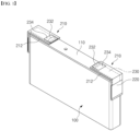
FIG. 1 is a drawing of a structure with a terminal structure applied to a prismatic secondary battery. -
FIG. 2 is a drawing of a plurality of terminal structures coupled to a busbar. -
FIG. 3 is a drawing of one embodiment of a terminal structure assembly. -
FIGS. 4 and 5 illustrate other embodiments of the terminal structure assembly. -
FIGS. 6 and7 illustrate exemplary embodiments of applying the terminal structure assembly to a plurality of secondary batteries. - The present invention may have various modifications and various embodiments, and thus specific embodiments thereof will be described in detail below.
- However, it should be understood that the present invention is not limited to the specific embodiments, and includes all modifications, equivalents, or alternatives within the spirit and technical scope of the present invention.
- The terms "comprise," "include," and "have" used herein designate the presence of characteristics, numbers, steps, actions, components, or members described in the specification or a combination thereof, and it should be understood that the possibility of the presence or addition of one or more other characteristics, numbers, steps, actions, components, members, or a combination thereof is not excluded in advance.
- In addition, in the present invention, when a part of a layer, film, region, plate, or the like is disposed "on" another part, this includes not only a case in which one part is disposed "directly on" another part, but a case in which still another part is interposed therebetween. In contrast, when a part of a layer, film, region, plate, or the like is disposed "under" another part, this includes not only a case in which one part is disposed "directly under" another part, but a case in which still another part is interposed therebetween. In addition, in the present application, "on" may include not only a case of being disposed on an upper portion but also a case of being disposed on a lower portion.
- The present invention relates to a terminal structure assembly, in one example, includes a terminal body providing an upper face and side face connected in a bent form with respect to the upper face, a plurality of terminal structures providing extension terminals exposed on the side face of the terminal body, and a busbar of conductive material coupled to all of the extension terminals provided on the plurality of terminal structures.
- The terminal structure assembly of the present invention, provided with the above configuration, has a plurality of terminal structures forming a single assembly with a busbar as a medium, and by applying the terminal structure assembly to a plurality of secondary batteries, it is possible to convert individual secondary batteries into secondary batteries with bidirectional terminals at once, and an electrical connection to a plurality of secondary batteries sharing the terminal structure assembly is completed.
- Accordingly, by applying the terminal structure assembly of the present invention to a battery module or pack comprising a plurality of secondary batteries, the terminal arrangement switching and busbar connection operation for all secondary batteries can be performed at once at the battery module/pack unit instead of at the individual battery cell unit, thereby reducing the manufacturing cost and labor of the battery module or pack.
- Hereinafter, specific embodiments of a secondary battery of the present invention will be described in detail with reference to the accompanying drawings. For reference, the directions of front, back, up, down, left, and right used in the following description to designate relative positions are for the purpose of understanding the invention and refer to the directions shown in the drawings unless otherwise specified.
-
FIG. 1 is an attached drawing to illustrate a configuration for converting asecondary battery 10 already manufactured with a unidirectional terminal arrangement to a bidirectional terminal arrangement, using aterminal structure 210 included in theterminal structure assembly 200 of the present invention. - Referring to
FIG. 1 , reference is made to asecondary battery 10, particularly a unidirectional prismaticsecondary battery 10 having a pair of electrode terminals 120, that is, a positive electrode terminal 122 and a negative electrode terminal 124, spaced apart on acap plate 110 forming an upper face of abattery case 100 having a hexahedral shape. Here, the prismaticsecondary battery 10 illustrated in the drawings is an example, and the ratio of width to length and height may vary, and for convenience of explanation, the directions of front and rear and up and down and left and right will be referred to with reference to the attached drawings. For example, one side of thebattery case 100 on which the positive electrode terminal 122 and the negative electrode terminal 124 are disposed is called the upper face, and the opposite side facing it is called the lower face. - The illustrated
secondary battery 10 includes aterminal structure 210. Theterminal structure 210 is a right-angled, bent structure that is coupled to at least one upper edge of thebattery case 100, and includes aterminal body 212 and anextension terminal 220. - The
terminal body 212 refers to a body of theterminal structure 210, including anupper face 213 that encloses either the positive electrode terminal 122 or the negative electrode terminal 124 from being exposed to the outside, and aside face 214 that is coupled to a side extending from the upper face of thebattery case 100. While the drawings show an example where theterminal structure 210 is coupled to both the positive electrode terminal 122 and the negative electrode terminal 124, respectively, according to an embodiment, theterminal structure 210 may optionally be coupled to only one of the positive electrode terminal 122 and the negative electrode terminal 124. - The
extension terminal 220 corresponds to a connection terminal that is electrically connected to the positive electrode terminal 122 or the negative electrode terminal 124 and extends to theside face 214 of theterminal body 212. In other words, the positive electrode terminal 122 or negative electrode terminal 124 is enclosed by theterminal body 212 and is not exposed to the outside, so theextension terminal 220 functions as a new positive electrode terminal 122 or negative electrode terminal 124 moved to the side face of thebattery case 100 instead of the upper face. - In addition, the
terminal body 212 is made of an insulating material, such as an electrically insulating resin or rubber material, so that the positive electrode terminal 122 or negative electrode terminal 124 covered on theupper face 213 of the terminal body is in an inactive state electrically isolated from the outside. In other words, in thesecondary battery 10 with theterminal structure 210, the existing positive electrode terminal 122 or negative electrode terminal 124 no longer functions as a connection terminal, and theextension terminal 220 on theterminal structure 210 functions as a new positive electrode terminal 122 or negative electrode terminal 124 that has moved the position. - As such, the position of the positive electrode terminal 122 and the negative electrode terminal 124, which are disposed together on the upper face of the
battery case 100, can be freely changed without a separate design change simply by applying theterminal structure 210. Accordingly, the present invention including theterminal structure 210 enables the position of the positive electrode terminal 122 and/or the negative electrode terminal 124 to be changed freely and easily for a secondary battery of the same form factor, thereby reducing the production cost of various types of prismatic secondary batteries. - In the illustrated embodiment, the positive electrode terminal 122 and/or the negative electrode terminal 124 are electrically connected to the
extension terminal 220 through anextension wire 230, wherein theextension wire 230 leading to theextension terminal 220 forms ajoint part 232 with respect to the positive electrode terminal 122 and/or the negative electrode terminal 124, wherein thejoint part 232 provides a mechanically and electrically robust connection between theextension wire 230 and the electrode terminal 120. For example, thejoint part 232 may be formed by welding. - The
extension wire 230 is not exposed outside of theterminal body 212. For example, theextension wire 230 may be embedded within theterminal body 212 of an electrically insulating resin material, such as by insert molding, etc. In addition, thejoint part 232 is also insulated from the outside. The external insulation of thejoint part 232 may be provided by at least one of an insulating cover, an insulating tape, and a curable insulating layer. - Here, a curable insulating layer refers to an insulating layer formed by curing after a flowable insulating resin is applied to the
joint part 232, and inFIG. 1 , a configuration in which a film form ofinsulation tape 234 having an adhesive layer insulates thejoint part 232 is shown. - Based on such a basic configuration of the
terminal structure 210, aterminal structure assembly 200 according to the present invention will be described.FIGS. 2 and 3 illustrate aterminal structure assembly 200 according to one embodiment of the present invention. - Referring to
FIGS. 2 and 3 , theterminal structure assembly 200 of the present invention includes a plurality ofterminal structures 210, and also includes abusbar 240 made of a conductive material that is coupled to all of theextension terminals 220 provided on the plurality ofterminal structures 210. With the medium of thebusbar 240, the plurality ofterminal structures 210 form a single assembly, and by applying theterminal structure assembly 200 to the plurality ofsecondary batteries 10, an electrical connection is made to the plurality ofsecondary batteries 10 sharing theterminal structure assembly 200, with individualsecondary batteries 10 be able to be converted to bi-directional terminals at once. This will be described in more detail in the corresponding sections below. - As shown, the plurality of
terminal structures 210 are aligned in a row withterminal body 212 facing the same direction, andbusbars 240 are coupled to the alignedextension terminals 220 at once. Thebusbars 240 are made of a conductive material, so that theextension terminals 220 of eachterminal structure 210 connected by thebusbars 240 are electrically connected to each other. In one example, thebusbars 240 may be welded to theextension terminals 220. -
FIGS. 4 and 5 illustrate various coupling structures of theextension terminal 220 and thebusbar 240. According to the embodiment shown inFIG. 4 , a side end of theterminal structure 210 is provided with afastening part 216 into which thebusbar 240 is inserted and coupled. Thefastening part 216 forms a gap corresponding to a thickness of thebusbar 240 with respect to theextension terminal 220, such that thebusbar 240 can be inserted and secured in the gap between thefastening part 216 and theextension terminal 220. Thefastening part 216 may be separately manufactured and mounted to the end of theextension terminal 220, or it may be formed by bending theextension terminal 220, which may be made of metal material. -
FIG. 5 illustrates one embodiment of bending anextension terminal 220, which is made of metal material, to form afastening part 216, wherein thefastening part 216 has aconnection socket 222 into which theextension terminal 220 is bent. Theconnection socket 222 is a connection groove deep enough to be inserted into substantially all of thebusbar 240 and may form a spring structure that elastically secures thebusbar 240. In other words, as shown inFIG. 5 , theconnection socket 222 may form a curved, deformable cross-section that is elastic with respect to thebusbar 240. The support structure of thebusbar 240 is enhanced by theconnection socket 222 forming a spring structure. - In addition, the free end of the
connection socket 222 may be formed a winding curved surface. This is to prevent thebusbar 240 from being scratched by the entrance edge of theconnection socket 222 as it is inserted into theconnection socket 222, and to prevent thebusbar 240 with a damaged surface from being easily corroded. - Here, even in the case of the
terminal structure 210 having thefastening part 216 ofFIGS. 4 and 5 , thebusbar 240 inserted into theconnection socket 222 may be welded to theextension terminal 220 for more rigid support of thebusbar 240. -
FIGS. 6 and7 are exemplary drawings of an application of theterminal structure assembly 200 described in detail in the first embodiment to a plurality ofsecondary batteries 10, and the advantages of theterminal structure assembly 200 of the present invention will be more clearly understood with reference toFIGS. 6 and7 . - The depicted
secondary battery 10 relates to a unidirectionalsecondary battery 10 having a positive electrode terminal 122 and a negative electrode terminal 124 spaced apart on an upper face of abattery case 100 forming a hexahedral shape. A plurality of suchsecondary batteries 10 are arranged in a row along a thickness direction. - The
terminal structure assembly 200, according to a first embodiment, is coupled to a plurality ofsecondary batteries 10 arranged in a row. In other words, as described with reference toFIG. 1 , theterminal body 212 of eachterminal structure 210 is coupled to wrap around the positive electrode terminal 122 or negative electrode terminal 124 of the upper face of thesecondary battery 10 corresponding to itself, and accordingly, the plurality ofsecondary batteries 10 coupled to theterminal structure assembly 200 are collectively switched in terminal arrangement to a bidirectionalsecondary battery 10. - Further, by the
busbar 240 coupled to theextension terminal 220 of eachterminal structure 210, all of theterminal structures 210 of theterminal structure assembly 200 are in an electrically connected state, thereby automatically electrically connecting the plurality ofsecondary batteries 10 by theterminal structure assembly 200. -
FIG. 6 illustrates an example of threesecondary batteries 10 are connected in series by theterminal structure assembly 200. While threesecondary batteries 10 are exemplified in the drawings, it will be apparent to those of ordinary skill in the art that such a series connection structure can be extended to four or moresecondary batteries 10. Also, while theterminal structure assembly 200 ofFIGS. 2 and 3 is shown in the drawings, it will be apparent that theterminal structure assembly 200 ofFIGS. 4 and 5 can be applied. - Referring to
FIG. 6 , theterminal structure assembly 200 provides twoterminal structures 210. Further, the plurality ofsecondary batteries 10 are aligned along a thickness direction such that electrode terminals 120 of different polarities face electrode terminals 120 of other neighboringsecondary batteries 10, theterminal structure assembly 200 having twoterminal structures 210 are alternately coupled to both sides of the plurality of secondary batteries 10 (alternately coupled one to each side while skipping one secondary battery), thereby the plurality ofsecondary batteries 10 are connected in series. -
FIG. 7 illustrates a case where threesecondary batteries 10 are connected in parallel. In an example ofFIG. 7 , theterminal structure assembly 200 has a number ofterminal structures 210 corresponding to the number of the plurality of secondary batteries 10 (three inFIG. 7 ). Further, the plurality ofsecondary batteries 10 are aligned along a thickness direction such that electrode terminals 120 of the same polarity as electrode terminals 120 of other adjacentsecondary batteries 10 face each other, and the plurality ofsecondary batteries 10 are connected in parallel by theterminal structure assembly 200 coupling to each of two sides of the plurality ofsecondary batteries 10. - As such, by applying the
terminal structure assembly 200 of the present invention, the individualsecondary batteries 10 are converted from unidirectionalsecondary batteries 10 to bidirectionalsecondary batteries 10 at once, and the electrical connection to the plurality ofsecondary batteries 10 to which theterminal structure assembly 200 is applied is completed. Thus, when theterminal structure assembly 200 of the present invention is applied to a battery module or pack having a plurality of unidirectionalsecondary batteries 10, the battery module/pack can reduce manufacturing costs and time, etc. - For reference, although not shown, by combining the connection structures of
FIGS. 6 and7 , it is easy to implement a variety of series and parallel connections in addition to series and parallel connections. - As above, the present invention has been described in more detail through the drawings and embodiments. However, since the configuration described in the drawings or embodiments described herein is merely one embodiment of the present invention and do not represent the overall technical spirit of the invention, it should be understood that the invention covers various equivalents, modifications, and substitutions at the time of filing of this application.
-
- 10: secondary battery
- 100: battery case
- 110: cap plate
- 120: electrode terminal
- 122: positive electrode terminal
- 124: negative electrode terminal
- 200: terminal structure assembly
- 210: terminal structure
- 212: terminal body
- 213: upper face
- 214: side face
- 216: fastening part
- 220: extension terminal
- 222: connection socket
- 230: extension wire
- 232: joint part
- 234: insulation tape
- 240: busbar
Claims (11)
- A terminal structure assembly comprising:a plurality of terminal bodies each having an upper face and a side face connected to the upper face, each terminal body being bent at a location where the upper face meets the side face;a plurality of terminal structures including an extension terminal exposed on the side face of each terminal body; anda busbar of conductive material coupled to all of the extension terminals of the plurality of terminal structures.
- The terminal structure assembly of claim 1, wherein the plurality of terminal structures are aligned in a row.
- The terminal structure assembly of claim 2, wherein the busbar is welded to the extension terminals.
- The terminal structure assembly of claim 1, wherein a side end of each terminal structure has a fastening part into which the busbar is inserted.
- The terminal structure assembly of claim 4, wherein each fastening part has a connection socket and the extension terminals each have a bent shape.
- The terminal structure assembly of claim 5, wherein each connection socket has a spring structure that elastically secures the busbar therein.
- The terminal structure assembly of claim 6, wherein a free end of each connection socket has a winding curved surface.
- The terminal structure assembly of claim 5, wherein the busbar is welded to each extension terminal.
- A secondary battery assembly, comprising:the terminal structure assembly of claim 1; anda plurality of secondary batteries arranged in a row, each secondary battery having positive and negative electrode terminals spaced apart on an upper face of a battery case having a hexahedral shape,wherein the terminal structure assembly is coupled to the plurality of secondary batteries, and the busbar electrically connects the plurality of secondary batteries to one another.
- The secondary battery assembly of claim 9, wherein the terminal structure assembly has two terminal structures, and
the plurality of secondary batteries is aligned along a thickness direction with electrode terminals of different polarities facing electrode terminals of adjacent ones of the secondary batteries, and the plurality of secondary batteries is connected in series. - The secondary battery assembly of claim 9, wherein the terminal structure assembly has a number of terminal structures equal to a number of the plurality of secondary batteries,the plurality of secondary batteries are aligned with one another along a thickness direction such that electrode terminals of the plurality of secondary batteries face electrode terminals of the same polarity as electrode terminals of adj acent ones of the secondary batteries, andthe plurality of secondary batteries is connected in parallel.
Applications Claiming Priority (2)
| Application Number | Priority Date | Filing Date | Title |
|---|---|---|---|
| KR1020220140666A KR20240059428A (en) | 2022-10-27 | 2022-10-27 | Terminal structures assembly having integrated bus bar |
| PCT/KR2023/016615 WO2024090978A1 (en) | 2022-10-27 | 2023-10-25 | Terminal structure assembly integrally including busbar |
Publications (2)
| Publication Number | Publication Date |
|---|---|
| EP4518005A4 EP4518005A4 (en) | 2025-03-05 |
| EP4518005A1 true EP4518005A1 (en) | 2025-03-05 |
Family
ID=90831338
Family Applications (1)
| Application Number | Title | Priority Date | Filing Date |
|---|---|---|---|
| EP23883083.0A Pending EP4518005A1 (en) | 2022-10-27 | 2023-10-25 | Terminal structure assembly integrally including busbar |
Country Status (5)
| Country | Link |
|---|---|
| EP (1) | EP4518005A1 (en) |
| JP (1) | JP2025519247A (en) |
| KR (1) | KR20240059428A (en) |
| CN (1) | CN119318071A (en) |
| WO (1) | WO2024090978A1 (en) |
Families Citing this family (1)
| Publication number | Priority date | Publication date | Assignee | Title |
|---|---|---|---|---|
| KR20250177748A (en) * | 2024-06-17 | 2025-12-24 | 주식회사 엘지에너지솔루션 | Battery cell assembly |
Family Cites Families (15)
| Publication number | Priority date | Publication date | Assignee | Title |
|---|---|---|---|---|
| JPS6074473U (en) * | 1983-10-28 | 1985-05-25 | 新神戸電機株式会社 | storage battery |
| KR101627631B1 (en) * | 2012-04-12 | 2016-06-07 | 삼성에스디아이 주식회사 | Rechargeable battery and module thereof |
| JP2014107201A (en) * | 2012-11-29 | 2014-06-09 | Yazaki Corp | Conduction member and manufacturing method of conduction member |
| KR20140094207A (en) * | 2013-01-21 | 2014-07-30 | 삼성에스디아이 주식회사 | Rechargeable battery module |
| DE202013103444U1 (en) * | 2013-07-31 | 2014-11-04 | Weidmüller Interface GmbH & Co. KG | Contact element for a plug-in arrangement of a particular externally guided bus system |
| JP2015179578A (en) * | 2014-03-18 | 2015-10-08 | 株式会社リチウムエナジージャパン | Storage element and power supply module |
| KR102408824B1 (en) * | 2015-06-22 | 2022-06-13 | 삼성에스디아이 주식회사 | Rechargeable battery and rechargeable battery module |
| DE102016116842B3 (en) * | 2016-09-08 | 2018-02-15 | Lisa Dräxlmaier GmbH | Connector for electrically connecting two electrical assemblies |
| KR102425799B1 (en) * | 2017-09-07 | 2022-07-28 | 삼성에스디아이 주식회사 | Secondary Battery |
| KR102578860B1 (en) | 2018-02-27 | 2023-09-13 | 삼성에스디아이 주식회사 | Rechargeable battery |
| JP7407424B2 (en) * | 2018-11-20 | 2024-01-04 | パナソニックIpマネジメント株式会社 | Energy storage module |
| KR102789863B1 (en) * | 2019-09-02 | 2025-03-31 | 주식회사 엘지에너지솔루션 | Connector |
| KR102672499B1 (en) * | 2020-12-21 | 2024-06-07 | 에스케이온 주식회사 | Bus bar and battery module including the same |
| KR20220134301A (en) * | 2021-03-26 | 2022-10-05 | 에스케이온 주식회사 | Battery pack |
| KR20220140666A (en) | 2021-04-10 | 2022-10-18 | 이동진 | Replaceable hydrogen fuel platform |
-
2022
- 2022-10-27 KR KR1020220140666A patent/KR20240059428A/en not_active Ceased
-
2023
- 2023-10-25 EP EP23883083.0A patent/EP4518005A1/en active Pending
- 2023-10-25 WO PCT/KR2023/016615 patent/WO2024090978A1/en not_active Ceased
- 2023-10-25 CN CN202380045155.4A patent/CN119318071A/en active Pending
- 2023-10-25 JP JP2024571388A patent/JP2025519247A/en active Pending
Also Published As
| Publication number | Publication date |
|---|---|
| CN119318071A (en) | 2025-01-14 |
| EP4518005A4 (en) | 2025-03-05 |
| JP2025519247A (en) | 2025-06-24 |
| KR20240059428A (en) | 2024-05-07 |
| WO2024090978A1 (en) | 2024-05-02 |
Similar Documents
| Publication | Publication Date | Title |
|---|---|---|
| KR102461833B1 (en) | Battery module | |
| JP7258278B2 (en) | Battery pack with movable busbar assembly and secondary battery including the same | |
| US11380955B2 (en) | Battery module, and battery pack and vehicle comprising the same | |
| US10236485B2 (en) | Battery module | |
| US11456502B2 (en) | Battery module, battery pack comprising same battery module, and vehicle comprising same battery pack | |
| KR20050121907A (en) | Secondary battery and electrodes assembly using the same | |
| US20110104572A1 (en) | Electrode assembly for secondary battery and method of making the electrode assembly | |
| JP2009059681A (en) | Battery pack and battery case | |
| WO2019031702A1 (en) | Battery cell frame and battery module comprising same | |
| KR102214538B1 (en) | Unit battery module and Battery module having the same | |
| JP2019512863A (en) | Battery module and battery pack including the same | |
| KR20210011641A (en) | Battery module and battery pack including the same | |
| KR20190128812A (en) | Bettery module | |
| EP4518005A1 (en) | Terminal structure assembly integrally including busbar | |
| EP4044348A1 (en) | Battery pack | |
| KR102785764B1 (en) | Secondart Battery | |
| EP4376207B1 (en) | Secondary battery with improved connection structure | |
| KR20230058852A (en) | Battery Module and Battery Pack Having the same | |
| US20250070423A1 (en) | Secondary Battery with Improved Terminal Structure | |
| KR101826862B1 (en) | Battery Pack Having Protection Module | |
| US20230378620A1 (en) | Pouch-type battery cell, and battery cell assembly and battery pack having the same | |
| JP7849480B2 (en) | Secondary battery with improved terminal structure | |
| JP7835900B2 (en) | Battery module | |
| JP7831913B2 (en) | Secondary battery with improved terminal structure | |
| EP4407771A2 (en) | Rechargeable battery pack |
Legal Events
| Date | Code | Title | Description |
|---|---|---|---|
| STAA | Information on the status of an ep patent application or granted ep patent |
Free format text: STATUS: THE INTERNATIONAL PUBLICATION HAS BEEN MADE |
|
| PUAI | Public reference made under article 153(3) epc to a published international application that has entered the european phase |
Free format text: ORIGINAL CODE: 0009012 |
|
| STAA | Information on the status of an ep patent application or granted ep patent |
Free format text: STATUS: REQUEST FOR EXAMINATION WAS MADE |
|
| 17P | Request for examination filed |
Effective date: 20241127 |
|
| A4 | Supplementary search report drawn up and despatched |
Effective date: 20250128 |
|
| AK | Designated contracting states |
Kind code of ref document: A1 Designated state(s): AL AT BE BG CH CY CZ DE DK EE ES FI FR GB GR HR HU IE IS IT LI LT LU LV MC ME MK MT NL NO PL PT RO RS SE SI SK SM TR |
|
| STAA | Information on the status of an ep patent application or granted ep patent |
Free format text: STATUS: EXAMINATION IS IN PROGRESS |
|
| DAV | Request for validation of the european patent (deleted) | ||
| DAX | Request for extension of the european patent (deleted) | ||
| 17Q | First examination report despatched |
Effective date: 20260129 |