EP4517991A1 - Battery and electric apparatus - Google Patents
Battery and electric apparatus Download PDFInfo
- Publication number
- EP4517991A1 EP4517991A1 EP23795299.9A EP23795299A EP4517991A1 EP 4517991 A1 EP4517991 A1 EP 4517991A1 EP 23795299 A EP23795299 A EP 23795299A EP 4517991 A1 EP4517991 A1 EP 4517991A1
- Authority
- EP
- European Patent Office
- Prior art keywords
- treating
- battery
- fluid
- recycling
- space
- Prior art date
- Legal status (The legal status is an assumption and is not a legal conclusion. Google has not performed a legal analysis and makes no representation as to the accuracy of the status listed.)
- Pending
Links
Images


Classifications
-
- H—ELECTRICITY
- H01—ELECTRIC ELEMENTS
- H01M—PROCESSES OR MEANS, e.g. BATTERIES, FOR THE DIRECT CONVERSION OF CHEMICAL ENERGY INTO ELECTRICAL ENERGY
- H01M50/00—Constructional details or processes of manufacture of the non-active parts of electrochemical cells other than fuel cells, e.g. hybrid cells
- H01M50/30—Arrangements for facilitating escape of gases
- H01M50/383—Flame arresting or ignition-preventing means
-
- H—ELECTRICITY
- H01—ELECTRIC ELEMENTS
- H01M—PROCESSES OR MEANS, e.g. BATTERIES, FOR THE DIRECT CONVERSION OF CHEMICAL ENERGY INTO ELECTRICAL ENERGY
- H01M10/00—Secondary cells; Manufacture thereof
- H01M10/42—Methods or arrangements for servicing or maintenance of secondary cells or secondary half-cells
- H01M10/4207—Methods or arrangements for servicing or maintenance of secondary cells or secondary half-cells for several batteries or cells simultaneously or sequentially
-
- H—ELECTRICITY
- H01—ELECTRIC ELEMENTS
- H01M—PROCESSES OR MEANS, e.g. BATTERIES, FOR THE DIRECT CONVERSION OF CHEMICAL ENERGY INTO ELECTRICAL ENERGY
- H01M10/00—Secondary cells; Manufacture thereof
- H01M10/60—Heating or cooling; Temperature control
- H01M10/61—Types of temperature control
- H01M10/613—Cooling or keeping cold
-
- H—ELECTRICITY
- H01—ELECTRIC ELEMENTS
- H01M—PROCESSES OR MEANS, e.g. BATTERIES, FOR THE DIRECT CONVERSION OF CHEMICAL ENERGY INTO ELECTRICAL ENERGY
- H01M10/00—Secondary cells; Manufacture thereof
- H01M10/60—Heating or cooling; Temperature control
- H01M10/62—Heating or cooling; Temperature control specially adapted for specific applications
- H01M10/625—Vehicles
-
- H—ELECTRICITY
- H01—ELECTRIC ELEMENTS
- H01M—PROCESSES OR MEANS, e.g. BATTERIES, FOR THE DIRECT CONVERSION OF CHEMICAL ENERGY INTO ELECTRICAL ENERGY
- H01M10/00—Secondary cells; Manufacture thereof
- H01M10/60—Heating or cooling; Temperature control
- H01M10/65—Means for temperature control structurally associated with the cells
- H01M10/655—Solid structures for heat exchange or heat conduction
- H01M10/6556—Solid parts with flow channel passages or pipes for heat exchange
-
- H—ELECTRICITY
- H01—ELECTRIC ELEMENTS
- H01M—PROCESSES OR MEANS, e.g. BATTERIES, FOR THE DIRECT CONVERSION OF CHEMICAL ENERGY INTO ELECTRICAL ENERGY
- H01M10/00—Secondary cells; Manufacture thereof
- H01M10/60—Heating or cooling; Temperature control
- H01M10/65—Means for temperature control structurally associated with the cells
- H01M10/656—Means for temperature control structurally associated with the cells characterised by the type of heat-exchange fluid
- H01M10/6567—Liquids
-
- H—ELECTRICITY
- H01—ELECTRIC ELEMENTS
- H01M—PROCESSES OR MEANS, e.g. BATTERIES, FOR THE DIRECT CONVERSION OF CHEMICAL ENERGY INTO ELECTRICAL ENERGY
- H01M10/00—Secondary cells; Manufacture thereof
- H01M10/60—Heating or cooling; Temperature control
- H01M10/65—Means for temperature control structurally associated with the cells
- H01M10/656—Means for temperature control structurally associated with the cells characterised by the type of heat-exchange fluid
- H01M10/6567—Liquids
- H01M10/6568—Liquids characterised by flow circuits, e.g. loops, located externally to the cells or cell casings
-
- H—ELECTRICITY
- H01—ELECTRIC ELEMENTS
- H01M—PROCESSES OR MEANS, e.g. BATTERIES, FOR THE DIRECT CONVERSION OF CHEMICAL ENERGY INTO ELECTRICAL ENERGY
- H01M50/00—Constructional details or processes of manufacture of the non-active parts of electrochemical cells other than fuel cells, e.g. hybrid cells
- H01M50/30—Arrangements for facilitating escape of gases
-
- H—ELECTRICITY
- H01—ELECTRIC ELEMENTS
- H01M—PROCESSES OR MEANS, e.g. BATTERIES, FOR THE DIRECT CONVERSION OF CHEMICAL ENERGY INTO ELECTRICAL ENERGY
- H01M50/00—Constructional details or processes of manufacture of the non-active parts of electrochemical cells other than fuel cells, e.g. hybrid cells
- H01M50/30—Arrangements for facilitating escape of gases
- H01M50/317—Re-sealable arrangements
-
- H—ELECTRICITY
- H01—ELECTRIC ELEMENTS
- H01M—PROCESSES OR MEANS, e.g. BATTERIES, FOR THE DIRECT CONVERSION OF CHEMICAL ENERGY INTO ELECTRICAL ENERGY
- H01M50/00—Constructional details or processes of manufacture of the non-active parts of electrochemical cells other than fuel cells, e.g. hybrid cells
- H01M50/30—Arrangements for facilitating escape of gases
- H01M50/342—Non-re-sealable arrangements
- H01M50/3425—Non-re-sealable arrangements in the form of rupturable membranes or weakened parts, e.g. pierced with the aid of a sharp member
-
- H—ELECTRICITY
- H01—ELECTRIC ELEMENTS
- H01M—PROCESSES OR MEANS, e.g. BATTERIES, FOR THE DIRECT CONVERSION OF CHEMICAL ENERGY INTO ELECTRICAL ENERGY
- H01M50/00—Constructional details or processes of manufacture of the non-active parts of electrochemical cells other than fuel cells, e.g. hybrid cells
- H01M50/60—Arrangements or processes for filling or topping-up with liquids; Arrangements or processes for draining liquids from casings
- H01M50/609—Arrangements or processes for filling with liquid, e.g. electrolytes
- H01M50/627—Filling ports
-
- H—ELECTRICITY
- H01—ELECTRIC ELEMENTS
- H01M—PROCESSES OR MEANS, e.g. BATTERIES, FOR THE DIRECT CONVERSION OF CHEMICAL ENERGY INTO ELECTRICAL ENERGY
- H01M50/00—Constructional details or processes of manufacture of the non-active parts of electrochemical cells other than fuel cells, e.g. hybrid cells
- H01M50/60—Arrangements or processes for filling or topping-up with liquids; Arrangements or processes for draining liquids from casings
- H01M50/673—Containers for storing liquids; Delivery conduits therefor
- H01M50/682—Containers for storing liquids; Delivery conduits therefor accommodated in battery or cell casings
-
- H—ELECTRICITY
- H01—ELECTRIC ELEMENTS
- H01M—PROCESSES OR MEANS, e.g. BATTERIES, FOR THE DIRECT CONVERSION OF CHEMICAL ENERGY INTO ELECTRICAL ENERGY
- H01M2220/00—Batteries for particular applications
- H01M2220/20—Batteries in motive systems, e.g. vehicle, ship, plane
-
- Y—GENERAL TAGGING OF NEW TECHNOLOGICAL DEVELOPMENTS; GENERAL TAGGING OF CROSS-SECTIONAL TECHNOLOGIES SPANNING OVER SEVERAL SECTIONS OF THE IPC; TECHNICAL SUBJECTS COVERED BY FORMER USPC CROSS-REFERENCE ART COLLECTIONS [XRACs] AND DIGESTS
- Y02—TECHNOLOGIES OR APPLICATIONS FOR MITIGATION OR ADAPTATION AGAINST CLIMATE CHANGE
- Y02E—REDUCTION OF GREENHOUSE GAS [GHG] EMISSIONS, RELATED TO ENERGY GENERATION, TRANSMISSION OR DISTRIBUTION
- Y02E60/00—Enabling technologies; Technologies with a potential or indirect contribution to GHG emissions mitigation
- Y02E60/10—Energy storage using batteries
Definitions
- the present application relates to the field of battery technologies, in particular to a battery and an electrical device.
- Batteries are widely used in electronic devices, such as mobile phones, laptops, electric scooters, electric cars, electric airplanes, electric ships, electric toy cars, electric toy ships, electric toy planes, and electric tools due to their advantages of high specific energy, high power density, etc.
- lithium-ion batteries have been widely used due to their advantages of high energy density, high output power, long cycle life, low environmental pollution, etc.
- safety performance is also a non-negligible problem. If the safety problem of a battery cannot be guaranteed, the battery cannot be used. How to improve the safety of a battery has always been a research issue for those skilled in the art.
- the present application provides a battery with high safety and an electrical device.
- the present application provides a battery including a battery cell and a release treating device, where the battery cell has a pressure relief mechanism configured to release a substance inside the battery cell; the release treating device includes a treating space configured to be connected to an outer surface of the pressure relief mechanism so as to allow the substance released by the pressure relief mechanism to enter the treating space; and the release treating device further includes a treating member for treating the substance to reduce a specified parameter of the substance, where the treating member is disposed in the treating space.
- the substance released from the battery cell are treated by the treating member to reduce the specified parameter of the substance, and after the specified parameter of the substance is reduced, the possibility of combustion of the substance is greatly reduced, so that the battery is less prone to ignition when thermal runaway occurs, which is conducive to improving the safety of the battery.
- the specified parameter is at least one of temperature, concentration of combustible particles, or concentration of the combustible gas, so that the release treating device can reduce the possibility of combustion of the substance by reducing the specified parameter, and the battery is less prone to ignition, which is conducive to improving the safety of the battery.
- the treating member includes a spray assembly for spraying treating fluid into the treating space and a fluid supply assembly for delivering the treating fluid to the spray assembly, where the spray assembly is disposed in the treating space; and the fluid supply assembly is connected to the spray assembly.
- the battery includes a battery box in which the battery cell is placed, and the release treating device further includes a treating box in which the treating space is formed and which is provided with an opening connected to the treating space, and fits on an end surface of the battery box through the opening.
- the spray assembly is configured to face the end surface to spray the treating fluid towards the end surface, so that the treating fluid sprayed by the spray assembly can reach the end surface of the battery box, exchange heat with the battery box, and take away the heat generated by the battery cell during thermal runaway to cool the battery cell.
- the battery includes a box body in which a divider is provided to divide the box body into two spaces, one of the two spaces being the treating space, and the other of the two spaces being for placing the battery cell.
- the spray assembly is configured to face the divider, for allowing the treating fluid to exchange heat with the divider, and the treating fluid can take away the heat generated by the thermal runaway of the battery cell to cool the battery cell, which is conducive to reducing the possibility of danger and improving the safety of the battery.
- the spray assembly includes a fluid supply pipeline connected to the fluid supply assembly and a nozzle connected to the fluid supply pipeline, and the fluid supply pipeline is used for delivering the treating fluid to the nozzle.
- a connecting portion is disposed on the fluid supply pipeline, a connecting groove is disposed on an inner wall of the treating space, and the connecting portion is connected to the connecting groove, so that the treating member is fixed in the treating space, which can avoid movement of the fluid supply pipeline and the nozzle in the treating space and reduce the possibility of collision.
- the fluid supply pipeline is configured in a spiral shape and a plurality of the nozzles are provided at equal intervals along the fluid supply pipeline, so that the treating fluid sprayed by the nozzles can be uniformly distributed in the treating space, and the path and time for treating the substance by the sprayed treating fluid can be extended, which is conducive to improving the effect of treating the substance by the treating fluid.
- the fluid supply assembly includes a fluid tank and a fluid delivery power member, and the fluid delivery power member is connected between the fluid tank and an inlet of the fluid supply pipeline.
- the release treating device further includes a connecting channel configured to connect the treating space to the outer surface of the pressure relief mechanism, so that the substance released at the pressure relief mechanism can enter the treating space through the connecting channel for treating.
- the battery further includes a recycling module for recycling the treating fluid, and the recycling module is connected to the treating space.
- the release treating device includes a recycling portion disposed in the treating space, the recycling portion is configured to protrude towards a bottom of the release treating device to form a recycling groove, the recycling portion is provided with a recycling hole in the protruding direction, and the recycling hole connects the recycling module with the recycling groove.
- the treating fluid collected by the recycling groove can be introduced into the recycling module via the recycling hole.
- the present application further provides an electrical device.
- the electrical device includes the battery provided in any of the foregoing technical solutions for providing electrical energy.
- the pressure relief mechanism of the battery cell can release a substance inside the battery cell
- the treating space of the release treating device is connected to the pressure relief mechanism
- the treating member in the treating space can treat the substance released by the pressure relief mechanism into the treating space to reduce a specified parameter of the substance.
- the reference numerals in specific implementations are as follows: 20. Battery cell; 21. End cover; 22. Shell; 23. Cell core assembly; 200. Controller; 300. Motor; 1000. Vehicle; 1. Battery cell; 2. Treating space; 3. Treating member; 31. Spray assembly; 311. Fluid supply pipeline; 3112. Connecting portion; 312. Nozzle; 32. Fluid supply assembly; 321. Fluid tank; 322. Fluid delivery power member; 4. Battery box; 5. Treating box; 50. Cover plate; 51. Recycling portion; 511. Recycling hole; 52. Recycling groove; 6. Connecting channel; 61. One-way valve; 62. Bent portion; 7. Discharge channel; 71. Discharge switch; 8. Recycling power member; 9. Recycling tank; 10. Filter member.
- an orientation or positional relationship indicated by the technical term “center”, “longitudinal”, “transverse”, “length”, “width”, “thickness”, “upper”, “lower”, “front”, “back”, “left”, “right”, “vertical”, “horizontal”, “top”, “bottom”, “internal”, “external”, “clockwise”, “counterclockwise”, “axial direction”, “radial direction”, “circumferential direction”, or the like is based on an orientation or positional relationship shown in the accompanying drawings, and is merely for ease of describing the embodiments of the present application and simplifying the description, but does not indicate or imply that an apparatus or an element referred to must have a specific orientation or be constructed and operated in a specific orientation, and therefore cannot be understood as a limitation on the embodiments of the present application.
- the inventor designed a cooling apparatus to cool a battery.
- the inventor further discovered that, even if the battery is cooled, when thermal runaway occurs, the battery still discharges high-temperature mixtures to the outside, posing a safety risk.
- a treatment structure may be disposed to treat the smoke generated by thermal runaway, so as to reduce a parameter related to flammability in the smoke, reduce the possibility of combustion of the smoke, and make the battery less prone to ignition when thermal runaway occurs, thereby improving the safety of the battery.
- the embodiments of the present application provide a battery cell.
- the battery cell may be used in an electrical device such as, but not limited to, a vehicle, a ship, or an aircraft.
- a power system of the electrical device may be constituted by the battery cell, the battery, or the like disclosed in the present application.
- the possibility of combustion of smoke discharged from the battery cell can be reduced, so the battery cell or the battery is less prone to ignition when thermal runaway occurs in the battery cell or the battery, and the safety of the battery cell and the battery can be improved.
- the battery 100 may be used not only as an operation power supply of the vehicle 1000, but also as a driving power supply of the vehicle 1000 to replace or partially replace fuel or natural gas to provide driving power for the vehicle 1000.
- the battery 100 includes a battery cell 20.
- the battery 100 may also include a plurality of battery cells 20, which may be in a series connection, a parallel connection, or a hybrid connection.
- the hybrid connection refers to a combination of series connection and parallel connection among the plurality of battery cells 20.
- the battery 100 may be in a form of a battery module constituted by a plurality of battery cells 20 connected in series, in parallel, or in hybrid, and then a plurality of battery modules are connected in series, in parallel, or in hybrid to form a whole accommodated in a box body 10.
- the battery 100 may further include other structures, for example, the battery 100 may further include a busbar for achieving electrical connection among the plurality of battery cells 20.
- Each battery cell 20 may be a secondary battery or a primary battery, or may be a lithium-sulfur battery, a sodium-ion battery, or a magnesium-ion battery, but is not limited to this.
- the battery cells 20 may be cylindrical, flat, cuboid, or in other shapes.
- Fig. 3 is an exploded structural diagram of a battery cell 20 provided in some embodiments of the present application.
- the battery cell 20 refers to the minimum unit that constitutes a battery.
- the battery cell 20 includes an end cover 21, a shell 22, a cell core assembly 23, a pressure relief mechanism (not shown), and other functional components.
- Fig. 4 is a schematic split diagram of a battery provided in some embodiments of the present application.
- the present application provides a battery which includes a battery cell 1 and a release treating device.
- the battery cell 1 has a pressure relief mechanism configured to be able to release a substance inside the battery cell 1
- the release treating device includes a treating space 2 configured to be able to be connected to an outer surface of the pressure relief mechanism so as to allow the substance released by the pressure relief mechanism to enter the treating space 2.
- the release treating device further includes a treating member 3 for treating the substance to reduce a specified parameter of the substance, and the treating member 3 is disposed in the treating space 2.
- the pressure relief mechanism may refer to a structure disposed on the battery cell 1, which can open when thermal runaway occurs in the battery cell 1 and the internal pressure exceeds a preset value, to release the substance inside the battery cell 1, so as to reduce the internal pressure of the battery cell 1 and improve the safety of the battery cell 1.
- the treating space 2 may refer to a space formed by the release treating device.
- the treating space 2 is connected to the outer surface of the pressure relief mechanism, so that the substance released by the pressure relief mechanism can discharge into the treating space 2.
- the treating space 2 can temporarily accommodate the substance.
- the treating space 2 may be independent of the space for placing the battery cell 1, or the treating space 2 and the space for placing the battery cell 1 may be configured as the same, so the discharged substance can be treated quickly and promptly, thereby improving the safety of the battery.
- the spray assembly 31 may refer to a combined component that can spray the treating fluid and scatter the treating fluid to form fine water drops.
- the spray assembly 31 is mounted in the treating space 2 and can spray the treating fluid into the treating space 2 to increase the contact area between the treating fluid and the substance in the treating space 2, which is conducive to improving the effect and efficiency of treating the substance by the treating member 3.
- the treating fluid After coming into contact with the substance, the treating fluid can not only exchange heat with the substance to reduce the temperature of the substance, but also can capture combustible particles in the substance to reduce the concentration of the combustible particles in the substance.
- the treating fluid may be ultra-pure water, fluorinated fluid, or the like. Such fluid is highly inert and less prone to chemical reaction with the substance, which is conducive to improving the safety of the treating fluid during use. After heated, the treating fluid can quickly vaporize to take away the heat from the substance. Meanwhile, the vaporized treating fluid can also reduce the concentration of the combustible particles or the combustible gas in the substance.
- the battery box 4 may be a structure in form of a box body in which an accommodating space is formed, the battery cell 1 is placed in the accommodating space, and the battery box 4 can protect the battery cell 1.
- the battery cell 1 is in contact with the battery box 4, so that the battery cell 1 and the battery box 4 can exchange heat.
- the treating box 5 may be a structure of box body that encloses the treating space 2 to accommodate and treat the substance released by the pressure relief mechanism.
- the opening may refer to a structure formed at the treating box 5, and it is connected to the treating space 2, so that the treating box 5 has an open structure, and the treating box 5 can cover the outer end surface of the battery box 4 through the opening.
- a cover plate 50 may be disposed on the opening of the treating box 5, the cover plate 50 is fixedly connected to the outer end surface of the battery box 4 by welding, and there is good heat transfer between the cover plate 50 and the battery box 4.
- the release treating device is disposed outside the battery box 4, which facilitates separate assembly of the battery box 4 and the release treating device during production.
- the two are assembled separately and then assembled together, which can effectively improve the manufacturing efficiency of this type of product and is conducive to mass production of the product.
- the spray assembly 31 is configured to face the end surface, so as to spray the treating fluid towards the end surface.
- the spray assembly 31 faces the end surface, so that the treating fluid sprayed by the spray assembly 31 can reach the end surface of the battery box 4, exchange heat with the battery box 4, and take away the heat generated by the battery cell 1 during thermal runaway to cool the battery cell 1, which is conducive to reducing the possibility of danger and improving the safety of the battery.
- the treating fluid can not only treat the substance, but also can cool the battery, which is conducive to improving the safety of the battery.
- the battery includes a box body in which a divider is provided to divide the box body into two spaces, one of the two spaces being the treating space 2, and the other of the two spaces being for placing the battery cell 1.
- the spray assembly 31 is configured to face the divider, for allowing the treating fluid to exchange heat with the divider.
- the spray assembly 31 faces the divider, so that the treating fluid sprayed by the spray assembly 31 can reach the divider, exchange heat with the divider, and take away the heat generated by the battery cell 1 during thermal runaway to cool the battery cell 1, which is conducive to reducing the possibility of danger and improving the safety of the battery.
- the treating fluid can not only treat the substance, but also can cool the battery cell 1, which is conducive to improving the safety of the battery.
- the spray assembly 31 includes a fluid supply pipeline 311 and a nozzle 312, the nozzle 312 is connected to the fluid supply pipeline 311, and the fluid supply pipeline 311 is connected to the fluid supply assembly 32.
- the nozzle 312 may refer to a device disposed in the treating space 2, and can treat the treating fluid into small droplets and spray the small droplets towards the treating space 2 to atomize the treating fluid, so that the treating fluid has a large area of contact with the substance, which is conducive to improving the effect of treating the substance.
- the fluid supply pipeline 311 may refer to a pipeline that can be arranged in the treating space 2, is connected to the nozzle 312, and can deliver the treating fluid with certain pressure to the nozzle 312.
- the nozzle 312 is connected to the fluid supply pipeline 311 to achieve relative fixation between the nozzle 312 and the fluid supply pipeline 311.
- a connecting portion 3112 is disposed on the fluid supply pipeline 311, a connecting groove is disposed on an inner wall of the treating space 2, and the connecting portion 3112 is connected to the connecting groove.
- the connecting portion 3112 may refer to a raised structure disposed on the fluid supply pipeline 311, and it may be formed by connecting a block structure to the fluid supply pipeline 311 through welding or bolt connection, or integrally formed with the fluid supply pipeline 311 in the manufacturing process of the fluid supply pipeline 311. Those skilled in the art can choose a method of forming the connecting portion 3112 according to an actual situation.
- the inner wall of the treating space 2 may refer to a side of the wall enclosing the treating space 2 that is close to the treating space 2.
- the inner wall of the treating space 2 may be a side of the divider that is close to the treating space 2, or a side of the box body that is close to the treating space 2.
- the inner wall of the treating space 2 may be the end surface of the battery box 4 that covers the opening of the treating box 5, or an inner side surface of the treating box 5 that is close to the treating space 2,.
- the connecting groove may refer to a groove structure disposed on the inner wall of the treating space 2 and matches the connecting portion 3112, and the connecting portion 3112 can be inserted into the connecting groove.
- the fluid supply pipeline 311 is configured in a spiral shape, and a plurality of nozzles 312 are provided, and the plurality of nozzles 312 are disposed at equal intervals along the fluid supply pipeline 311.
- the spiral shape may refer to a shape formed by bending the fluid supply pipeline 311 multiple times.
- the fluid supply pipeline 311 is arranged in the spiral shape in the treating space 2, which is conducive to uniform distribution of the fluid supply pipeline 311 in the treating space 2.
- the plurality of nozzles 312 are disposed at equal intervals along the fluid supply pipeline 311, so that the plurality of nozzles 312 on the fluid supply pipeline 311 can be uniformly arranged in the treating space 2, and the treating fluid sprayed by the nozzles 312 can be uniformly distributed in the treating space 2, which is conducive to improving the effect and efficiency of treating the substance by the treating fluid.
- the fluid supply assembly 32 includes a fluid tank 321 and a fluid delivery power member 322, and the fluid delivery power member 322 is connected between the fluid tank 321 and an inlet of the fluid supply pipeline 311.
- the fluid supply assembly 32 is arranged on the battery, and the fluid supply assembly 32 is connected to the battery box 4 by connectors such as connecting bolts, so that the fluid supply assembly 32 can be mounted together with the battery box 4 conveniently.
- the fluid supply assembly 32 may alternatively be arranged on an electrical device such as a vehicle, and the fluid supply assembly 32 is connected to the fluid supply pipeline 311 through a fluid delivery pipeline.
- the fluid supply assembly 32 is arranged on an electrical device for a vehicle, which can reduce the weight and structural redundancy of the battery. Those skilled in the art can choose the position of the fluid supply assembly 32 according to an actual situation.
- the fluid tank 321 may refer to a tank structure with a storage space inside, where the storage space contains the treating fluid.
- the fluid delivery power member 322 may be a fluid delivery pump, which can extract the treating fluid from the fluid tank 321 and deliver the treating fluid from the fluid tank 321 to the fluid supply pipeline 311 at certain pressure through the fluid supply pipeline 311, so that the treating fluid can be uniformly sprayed in the treating space 2 under its own pressure.
- the release treating device further includes a connecting channel 6 configured to connect the treating space 2 to the outer surface of the pressure relief mechanism.
- the connecting channel 6 may refer to a channel structure for connecting the treating space 2 with the outer surface of the pressure relief mechanism, which may be a channel structure formed in a component structure of the battery.
- the connecting channel 6 may be a channel formed on the divider.
- the connecting channel 6 may be a channel formed on the end surface of the box body.
- an additional connecting pipeline may be used as the channel structure to connect the treating space 2 to the outer surface of the pressure relief mechanism.
- a fluid blocking structure for blocking contact of the treating fluid with the battery cell 1 is disposed in the connecting channel 6.
- the fluid blocking structure may refer to a structure, which enables the substance discharged by the battery cell 1 during thermal runaway to flow into the treating space 2, and blocks the treating fluid in the treating space 2 from flowing to the pressure relief mechanism, thereby preventing the contact of the treating fluid with the battery cell 1 and reducing the probability of short-circuiting in the battery cell 1.
- the fluid blocking structure includes a one-way valve 61, an inlet of the one-way valve 61 is connected to the outer surface of the pressure relief mechanism, and an outlet of the one-way valve 61 is connected to the treating space 2.
- the one-way valve 61 connects the inlet with the outer surface of the pressure relief mechanism, and the outlet with the treating space 2, so that the substance can flow only from the pressure relief mechanism to the treating space 2, which can prevent the treating fluid from flowing to the pressure relief mechanism, avoid the contact of the treating fluid with the battery cell 1, and reduce the probability of short-circuiting in the battery cell 1.
- the fluid blocking structure includes a bent portion 62 for blocking the treating fluid from flowing to the pressure relief mechanism along the connecting channel 6.
- the bent portion 62 may be of an S-shaped bent structure disposed in the connecting channel 6, the structure can block the treating fluid, and the treating fluid is blocked from flowing to the pressure relief mechanism when flowing to the bent portion 62 along the connecting channel 6.
Landscapes
- Chemical & Material Sciences (AREA)
- Chemical Kinetics & Catalysis (AREA)
- Electrochemistry (AREA)
- General Chemical & Material Sciences (AREA)
- Engineering & Computer Science (AREA)
- Manufacturing & Machinery (AREA)
- Battery Mounting, Suspending (AREA)
- Secondary Cells (AREA)
- Gas Exhaust Devices For Batteries (AREA)
- Portable Nailing Machines And Staplers (AREA)
- Primary Cells (AREA)
Abstract
Description
- The present application claims priority to
Chinese Patent Application No. 202210447131.9, entitled "BATTERY AND ELECTRICAL DEVICE" filed on April 26, 2022 - The present application relates to the field of battery technologies, in particular to a battery and an electrical device.
- Batteries are widely used in electronic devices, such as mobile phones, laptops, electric scooters, electric cars, electric airplanes, electric ships, electric toy cars, electric toy ships, electric toy planes, and electric tools due to their advantages of high specific energy, high power density, etc.
- In the development of battery technologies, lithium-ion batteries have been widely used due to their advantages of high energy density, high output power, long cycle life, low environmental pollution, etc. At present, in addition to increasing energy densities of batteries, safety performance is also a non-negligible problem. If the safety problem of a battery cannot be guaranteed, the battery cannot be used. How to improve the safety of a battery has always been a research issue for those skilled in the art.
- In view of the above problems, the present application provides a battery with high safety and an electrical device.
- In a first aspect, the present application provides a battery including a battery cell and a release treating device, where the battery cell has a pressure relief mechanism configured to release a substance inside the battery cell; the release treating device includes a treating space configured to be connected to an outer surface of the pressure relief mechanism so as to allow the substance released by the pressure relief mechanism to enter the treating space; and the release treating device further includes a treating member for treating the substance to reduce a specified parameter of the substance, where the treating member is disposed in the treating space.
- With the above structure, the substance released from the battery cell are treated by the treating member to reduce the specified parameter of the substance, and after the specified parameter of the substance is reduced, the possibility of combustion of the substance is greatly reduced, so that the battery is less prone to ignition when thermal runaway occurs, which is conducive to improving the safety of the battery.
- In the battery provided in specific implementations of the present application, the specified parameter is at least one of temperature, concentration of combustible particles, or concentration of the combustible gas, so that the release treating device can reduce the possibility of combustion of the substance by reducing the specified parameter, and the battery is less prone to ignition, which is conducive to improving the safety of the battery.
- In the battery provided in specific implementations of the present application, the treating member includes a spray assembly for spraying treating fluid into the treating space and a fluid supply assembly for delivering the treating fluid to the spray assembly, where the spray assembly is disposed in the treating space; and the fluid supply assembly is connected to the spray assembly.
- In the battery provided in specific implementations of the present application, the battery includes a battery box in which the battery cell is placed, and the release treating device further includes a treating box in which the treating space is formed and which is provided with an opening connected to the treating space, and fits on an end surface of the battery box through the opening.
- In the battery provided in specific implementations of the present application, the spray assembly is configured to face the end surface to spray the treating fluid towards the end surface, so that the treating fluid sprayed by the spray assembly can reach the end surface of the battery box, exchange heat with the battery box, and take away the heat generated by the battery cell during thermal runaway to cool the battery cell.
- In the battery provided in specific implementations of the present application, the battery includes a box body in which a divider is provided to divide the box body into two spaces, one of the two spaces being the treating space, and the other of the two spaces being for placing the battery cell.
- In the battery provided in specific implementations of the present application, the spray assembly is configured to face the divider, for allowing the treating fluid to exchange heat with the divider, and the treating fluid can take away the heat generated by the thermal runaway of the battery cell to cool the battery cell, which is conducive to reducing the possibility of danger and improving the safety of the battery.
- In the battery provided in specific implementations of the present application, the spray assembly includes a fluid supply pipeline connected to the fluid supply assembly and a nozzle connected to the fluid supply pipeline, and the fluid supply pipeline is used for delivering the treating fluid to the nozzle.
- In the battery provided in specific implementations of the present application, a connecting portion is disposed on the fluid supply pipeline, a connecting groove is disposed on an inner wall of the treating space, and the connecting portion is connected to the connecting groove, so that the treating member is fixed in the treating space, which can avoid movement of the fluid supply pipeline and the nozzle in the treating space and reduce the possibility of collision.
- In the battery provided in specific implementations of the present application, the fluid supply pipeline is configured in a spiral shape and a plurality of the nozzles are provided at equal intervals along the fluid supply pipeline, so that the treating fluid sprayed by the nozzles can be uniformly distributed in the treating space, and the path and time for treating the substance by the sprayed treating fluid can be extended, which is conducive to improving the effect of treating the substance by the treating fluid.
- In the battery provided in specific implementations of the present application, the fluid supply assembly includes a fluid tank and a fluid delivery power member, and the fluid delivery power member is connected between the fluid tank and an inlet of the fluid supply pipeline.
- In the battery provided in specific implementations of the present application, the release treating device further includes a connecting channel configured to connect the treating space to the outer surface of the pressure relief mechanism, so that the substance released at the pressure relief mechanism can enter the treating space through the connecting channel for treating.
- In the battery provided in specific implementations of the present application, a fluid blocking structure for blocking contact of the treating fluid with the battery cell is disposed in the connecting channel, which can avoid the impact of the treating fluid on the battery cell and is conducive to avoiding the problems of short-circuiting and the like in the battery cell due to the contact of the treating fluid.
- In the battery provided in specific implementations of the present application, the fluid blocking structure includes a one-way valve, an inlet of the one-way valve is connected to the outer surface of the pressure relief mechanism, and an outlet of the one-way valve is connected to the treating space, so that the substance can flow only from the pressure relief mechanism to the treating space.
- In the battery provided in specific implementations of the present application, the fluid blocking structure includes a bent portion for blocking the treating fluid from flowing to the pressure relief mechanism along the connecting channel.
- In the battery provided in specific implementations of the present application, the battery cell includes a first end surface and a second end surface, the pressure relief mechanism is disposed on the first end surface, an electrode terminal is disposed on the second end surface, and the first end surface is opposite to the connecting channel, so that the electrode terminal can be far away from the pressure relief mechanism, which is conducive to reducing the possibility of contact between the treating fluid and the electrode terminal and improving the safety of the battery.
- In the battery provided in specific implementations of the present application, the projection of the connecting channel at least partially overlaps with the projection of the pressure relief mechanism in a running-through direction of the connecting channel, so that the substance released by the pressure relief mechanism from a release port can flow into the connecting channel through a short path and then enter the treating space.
- In the battery provided in specific implementations of the present application, the release treating device further includes a switch configured to connect the treating space to the outer surface of the pressure relief mechanism after being opened.
- In the battery provided in specific implementations of the present application, the switch includes a weak portion configured to connect the treating space to the outer surface of the pressure relief mechanism after being destroyed.
- In the battery provided in specific implementations of the present application, the battery cell includes a first end surface and a second end surface, the pressure relief mechanism is disposed on the first end surface, an electrode terminal is disposed on the second end surface, the first end surface is opposite to the weak portion, and the pressure relief mechanism and the electrode terminal are disposed at two ends of the battery cell respectively, so that the electrode terminal can be far away from the pressure relief mechanism, which is conducive to reducing the possibility of contact between the treating fluid and the electrode terminal and improving the safety of the battery.
- In the battery provided in specific implementations of the present application, in a thickness direction of the weak portion, a projection of the weak portion at least partially overlaps with a projection of the pressure relief mechanism, so that the substance released by the pressure relief mechanism from the release port can act on the switch formed by the weak portion.
- In the battery provided in specific implementations of the present application, the release treating device further includes a discharge channel configured to connect the treating space to an external space of the battery. The substance treated in the treating space are discharged to the external space of the battery via the discharge channel, thereby reducing accumulation of the released substance in the battery.
- In the battery provided in specific implementations of the present application, the release treating device further includes a discharge switch, the discharge switch is disposed in the discharge channel, and the discharge switch is configured to connect the treating space to the external space of the battery through the discharge channel after being opened.
- In the battery provided in specific implementations of the present application, the battery further includes a recycling module for recycling the treating fluid, and the recycling module is connected to the treating space.
- In the battery provided in specific implementations of the present application, the release treating device includes a recycling portion disposed in the treating space, the recycling portion is configured to protrude towards a bottom of the release treating device to form a recycling groove, the recycling portion is provided with a recycling hole in the protruding direction, and the recycling hole connects the recycling module with the recycling groove. The treating fluid collected by the recycling groove can be introduced into the recycling module via the recycling hole.
- In the battery provided in specific implementations of the present application, the recycling module includes a recycling power member and a recycling tank, an input end of the recycling power member is connected to the recycling hole, and an output end of the recycling power member is connected to the recycling tank, so that the treating fluid can quickly flow to the recycling tank under the action of the recycling power member.
- In the battery provided in specific implementations of the present application, the recycling module further includes a filter member, and the filter member is connected between the recycling hole and the input end of the recycling power member to filter the treating fluid and separate impurities such as combustible particles from the treating fluid, thereby improving the cleanliness of the treating fluid.
- In a second aspect, the present application further provides an electrical device. The electrical device includes the battery provided in any of the foregoing technical solutions for providing electrical energy.
- The technical solutions provided in the embodiments of the present disclosure bring at least the following beneficial effects:
In the battery provided by the present application that includes the battery cell and the release treating device, the pressure relief mechanism of the battery cell can release a substance inside the battery cell, the treating space of the release treating device is connected to the pressure relief mechanism, and the treating member in the treating space can treat the substance released by the pressure relief mechanism into the treating space to reduce a specified parameter of the substance. After the specified parameter of the substance is reduced, the possibility of combustion of the substance is greatly reduced, so that the battery is less prone to ignition when thermal runaway occurs, which is conducive to improving the safety of the battery. - The present application provides an electrical device, which includes the battery provided in the above technical solutions, so the electrical device has high safety.
- The above description is only a summary of the technical solutions of the present application. In order to understand the technical means in the present application more clearly, it can be implemented in accordance with the content of the specification; and in order to make the above and other objectives, features and advantages of the present application more obvious and easier to understand, and specific embodiments of the present application are cited below.
- Other advantages and benefits will become apparent to those of ordinary skill in the art by reading detailed description of the preferred implementations below. The accompanying drawings are only used to illustrate the preferred implementations and are not considered as a limitation on the present application. Throughout the accompanying drawings, the same reference numerals represent the same components. In the accompanying drawings:
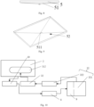
-
Fig. 1 is a schematic structural diagram of a vehicle provided in some embodiments of the present application; -
Fig. 2 is an exploded structural diagram of a battery in some embodiments of the present application; -
Fig. 3 is an exploded structural diagram of a battery cell in some embodiments of the present application; -
Fig. 4 is a split structural diagram of a battery in some embodiments of the present application; -
Fig. 5 is a split structural diagram of structures in a treating box in some embodiments of the present application; -
Fig. 6 is a schematic structural diagram of a one-way valve in a fluid blocking structure in some embodiments of the present application; -
Fig. 7 is a schematic structural diagram of a bent portion in the fluid blocking structure in some embodiments of the present application; -
Fig. 8 is a schematic structural diagram of the treating box in the battery in some embodiments of the present application from a first perspective; -
Fig. 9 is a schematic structural diagram of the treating box in the battery in some embodiments of the present application from a second perspective; and -
Fig. 10 is a schematic structural diagram of a recycling module in the battery in some embodiments of the present application. - The reference numerals in specific implementations are as follows: 20. Battery cell; 21. End cover; 22. Shell; 23. Cell core assembly; 200. Controller; 300. Motor; 1000. Vehicle; 1. Battery cell; 2. Treating space; 3. Treating member; 31. Spray assembly; 311. Fluid supply pipeline; 3112. Connecting portion; 312. Nozzle; 32. Fluid supply assembly; 321. Fluid tank; 322. Fluid delivery power member; 4. Battery box; 5. Treating box; 50. Cover plate; 51. Recycling portion; 511. Recycling hole; 52. Recycling groove; 6. Connecting channel; 61. One-way valve; 62. Bent portion; 7. Discharge channel; 71. Discharge switch; 8. Recycling power member; 9. Recycling tank; 10. Filter member.
- The embodiments of the technical solutions of the present application will be described in detail below with reference to the accompanying drawings. The following embodiments are only used to illustrate the technical solutions of the present application more clearly, and therefore are only examples and cannot be used to limit the protection scope of the present application.
- It should be noted that, unless otherwise specified, the technical or scientific terms used in the embodiments of the present application shall have the ordinary meaning understood by those skilled in the art to which the embodiments of the present application belong.
- In the description of the embodiments of the present application, an orientation or positional relationship indicated by the technical term "center", "longitudinal", "transverse", "length", "width", "thickness", "upper", "lower", "front", "back", "left", "right", "vertical", "horizontal", "top", "bottom", "internal", "external", "clockwise", "counterclockwise", "axial direction", "radial direction", "circumferential direction", or the like is based on an orientation or positional relationship shown in the accompanying drawings, and is merely for ease of describing the embodiments of the present application and simplifying the description, but does not indicate or imply that an apparatus or an element referred to must have a specific orientation or be constructed and operated in a specific orientation, and therefore cannot be understood as a limitation on the embodiments of the present application.
- In addition, the technical terms "first", "second", etc. are only for the sake of description, and cannot be understood as indicating or implying the relative importance or implicitly indicating the quantity of technical features indicated. In the description of the embodiments of the present application, the meaning of "a plurality of" is two or more, unless otherwise specifically defined.
- In the description of the embodiments of the present application, unless otherwise explicitly specified and defined, the technical terms "mounted", "connected", "connection", "fixed", etc. should be understood in a broad sense, for example, the "connection" may be fixed connection, detachable connection, integration, mechanical connection, electrical connection, direct connection, indirect connection via an intermediate medium, internal communication between two elements, or interaction between two elements. Those of ordinary skill in the art may appreciate the specific meanings of the foregoing terms in the embodiments of the present application according to specific circumstances.
- In the description of the embodiments of the present application, unless otherwise expressly specified and defined, a first feature "above" or "below" a second feature indicates that the first feature and the second feature are in direct contact, or are in indirect contact through an intermediate medium. Moreover, the first feature "on", "above", and "up" the second feature may be the first feature right above or obliquely above the second feature, or merely indicates that the level of the first feature is higher than that of the second feature. The first feature "below", "under", and "down" the second feature may be the first feature right below or obliquely below the second feature, or merely indicates that the level of the first feature is lower than that of the second feature.
- At present, in view of the development of the market situation, use of batteries is increasingly widespread. Batteries are not only used in energy storage power systems such as hydropower, firepower, wind power, and solar power plants, but also widely used in electric vehicles such as electric bicycles, electric motorcycles, and electric cars, as well as in various fields such as military equipment and aerospace. With the continuous expansion of the application fields of batteries, their market demand is also increasing.
- Existing batteries often discharge high-temperature mixtures when thermal runaway occurs. When the high-temperature mixtures are discharged from the batteries and come into full contact with air, the batteries are prone to deflagration or even explosion, which will affect the safety of relevant users.
- Based on the above phenomenon, the inventor designed a cooling apparatus to cool a battery. However, the inventor further discovered that, even if the battery is cooled, when thermal runaway occurs, the battery still discharges high-temperature mixtures to the outside, posing a safety risk.
- Therefore, the inventor's research suggested that non-combustible treatment can be performed on combustible smoke generated by thermal runaway of a battery cell. In order to treat smoke so as to reduce its flammability, the inventor found in research that a treatment structure may be disposed to treat the smoke generated by thermal runaway, so as to reduce a parameter related to flammability in the smoke, reduce the possibility of combustion of the smoke, and make the battery less prone to ignition when thermal runaway occurs, thereby improving the safety of the battery.
- Based on the above considerations, in order to improve the processing performance of a current collector, the inventor conducted in-depth research and designed a battery, in which a release treating device is disposed, a treating space of the release treating device is connected to a pressure relief mechanism of a battery cell, and when a substance released by the pressure relief mechanism enters the treating space, a treating member treats the released substance, so as to reduce a specified parameter, greatly reduce the possibility of combustion of the substance, and make the battery less prone to ignition when thermal runaway occurs, thereby improving the safety of the battery.
- The battery cell disclosed in the embodiments of the present application may be, but is not limited to, a rechargeable battery cell. The rechargeable battery cell refers to a battery that can activate active materials by means of charging after the battery cell is discharged and continue to be used. A pressure relief mechanism is disposed on the battery cell, and the pressure relief mechanism can release substances inside the battery cell to achieve pressure relief when thermal runaway occurs in the battery cell.
- The embodiments of the present application provide a battery cell. The battery cell may be used in an electrical device such as, but not limited to, a vehicle, a ship, or an aircraft. A power system of the electrical device may be constituted by the battery cell, the battery, or the like disclosed in the present application. In this case, the possibility of combustion of smoke discharged from the battery cell can be reduced, so the battery cell or the battery is less prone to ignition when thermal runaway occurs in the battery cell or the battery, and the safety of the battery cell and the battery can be improved.
- An embodiment of the present application provides an electrical device using a battery as a power supply. The electrical device may be, but is not limited to, a mobile phone, a tablet computer, a notebook computer, an electric toy, an electric tool, a scooter, an electric vehicle, a ship, or a spacecraft. The electric toy may include a fixed or mobile electric toy, such as a game console, an electric car toy, an electric ship toy, or an electric aircraft toy. The spacecraft may include an airplane, a rocket, a space shuttle, a spaceship, or the like.
- For convenient description, the following embodiments are described by an example of a
vehicle 1000 as an electrical device in an embodiment of the present application. - Refer to
Fig. 1 , which is a schematic structural diagram of avehicle 1000 provided in some embodiments of the present application. Thevehicle 1000 may be a fuel-powered vehicle, a gas-powered vehicle, or a new energy vehicle, and the new energy vehicle may be a battery electric vehicle, a hybrid vehicle, an extended-range vehicle, or the like. Abattery 100 is disposed inside thevehicle 1000, and thebattery 100 may be disposed at a bottom, head or tail of thevehicle 1000. Thebattery 100 may be used for supplying power to thevehicle 1000. For example, thebattery 100 may be used as an operation power supply of thevehicle 1000. Thevehicle 1000 may further include acontroller 200 and amotor 300. Thecontroller 200 is used to control thebattery 100 to supply power to themotor 300, for example, to meet the requirements for working electricity of thevehicle 1000 during startup, navigation and driving. - In some embodiments of the present application, the
battery 100 may be used not only as an operation power supply of thevehicle 1000, but also as a driving power supply of thevehicle 1000 to replace or partially replace fuel or natural gas to provide driving power for thevehicle 1000. - Refer to
Fig. 2 , which is a schematic structural diagram of abattery 100 provided in some embodiments of the present application. Thebattery 100 includes abattery cell 20. Thebattery 100 may also include a plurality ofbattery cells 20, which may be in a series connection, a parallel connection, or a hybrid connection. The hybrid connection refers to a combination of series connection and parallel connection among the plurality ofbattery cells 20. Thebattery 100 may be in a form of a battery module constituted by a plurality ofbattery cells 20 connected in series, in parallel, or in hybrid, and then a plurality of battery modules are connected in series, in parallel, or in hybrid to form a whole accommodated in abox body 10. Thebattery 100 may further include other structures, for example, thebattery 100 may further include a busbar for achieving electrical connection among the plurality ofbattery cells 20. - Each
battery cell 20 may be a secondary battery or a primary battery, or may be a lithium-sulfur battery, a sodium-ion battery, or a magnesium-ion battery, but is not limited to this. Thebattery cells 20 may be cylindrical, flat, cuboid, or in other shapes. - Refer to
Fig. 3 , which is an exploded structural diagram of abattery cell 20 provided in some embodiments of the present application. Thebattery cell 20 refers to the minimum unit that constitutes a battery. As shown inFig. 3 , thebattery cell 20 includes anend cover 21, ashell 22, acell core assembly 23, a pressure relief mechanism (not shown), and other functional components. - According to some embodiments of the present application,
Fig. 4 is a schematic split diagram of a battery provided in some embodiments of the present application. The present application provides a battery which includes abattery cell 1 and a release treating device. Thebattery cell 1 has a pressure relief mechanism configured to be able to release a substance inside thebattery cell 1, the release treating device includes a treatingspace 2 configured to be able to be connected to an outer surface of the pressure relief mechanism so as to allow the substance released by the pressure relief mechanism to enter the treatingspace 2. The release treating device further includes a treatingmember 3 for treating the substance to reduce a specified parameter of the substance, and the treatingmember 3 is disposed in the treatingspace 2. - The pressure relief mechanism may refer to a structure disposed on the
battery cell 1, which can open when thermal runaway occurs in thebattery cell 1 and the internal pressure exceeds a preset value, to release the substance inside thebattery cell 1, so as to reduce the internal pressure of thebattery cell 1 and improve the safety of thebattery cell 1. - The treating
space 2 may refer to a space formed by the release treating device. The treatingspace 2 is connected to the outer surface of the pressure relief mechanism, so that the substance released by the pressure relief mechanism can discharge into the treatingspace 2. The treatingspace 2 can temporarily accommodate the substance. In thebattery 100, the treatingspace 2 may be independent of the space for placing thebattery cell 1, or the treatingspace 2 and the space for placing thebattery cell 1 may be configured as the same, so the discharged substance can be treated quickly and promptly, thereby improving the safety of the battery. - The treating
member 3 may refer to a device with a function of treating substance, which is disposed in the treatingspace 2 and can treat the substance in the treatingspace 2, so that the specified parameter of the substance in the treatingspace 2 is reduced. - With the above solution, the substance released from the
battery cell 1 is treated by the treatingmember 3 to reduce the specified parameter of the substance, and after the specified parameter of the substance is reduced, the possibility of combustion of the substance is greatly reduced, so that the battery is less prone to ignition when thermal runaway occurs, which is conducive to improving the safety of the battery. - In some embodiments of the present application, the specified parameter is at least one of temperature, concentration of combustible particles, or concentration of the combustible gas.
- The temperature refers to the temperature of the substance. After the temperature of the substance decreases, the temperature of the substance is lower than an ignition point of the substance, so that the substance is less prone to ignition and combustion. The concentration of combustible particles refers to the quantity of combustible particles contained in the substance per unit volume. After the concentration of combustible particles decreases, the substance will be less prone to ignition. The concentration of a combustible gas refers to the quantity of the combustible gas contained in the substance per unit volume. After the concentration of the combustible gas decreases, the substance will be less prone to ignition. By reducing the above specified parameter, the probability of combustion of the substance will be effectively reduced, so that the battery is less prone to ignition, and the safety of the battery can be improved.
- In some embodiments of the present application, the treating
member 3 includes aspray assembly 31 configured to spray treating fluid into the treatingspace 2 and disposed in the treatingspace 2; afluid supply assembly 32 that is connected to thespray assembly 31 for supplying the treating fluid to thespray assembly 31. - The
spray assembly 31 may refer to a combined component that can spray the treating fluid and scatter the treating fluid to form fine water drops. Thespray assembly 31 is mounted in the treatingspace 2 and can spray the treating fluid into the treatingspace 2 to increase the contact area between the treating fluid and the substance in the treatingspace 2, which is conducive to improving the effect and efficiency of treating the substance by the treatingmember 3. - After coming into contact with the substance, the treating fluid can not only exchange heat with the substance to reduce the temperature of the substance, but also can capture combustible particles in the substance to reduce the concentration of the combustible particles in the substance. The treating fluid may be ultra-pure water, fluorinated fluid, or the like. Such fluid is highly inert and less prone to chemical reaction with the substance, which is conducive to improving the safety of the treating fluid during use. After heated, the treating fluid can quickly vaporize to take away the heat from the substance. Meanwhile, the vaporized treating fluid can also reduce the concentration of the combustible particles or the combustible gas in the substance.
- The
fluid supply assembly 32 can deliver the treating fluid with certain pressure to thespray assembly 31, and the treating fluid can be sprayed into the treatingspace 2 by thespray assembly 31 under the pressure, which is conducive to expanding the spray area of thespray assembly 31 and improving the uniformity of spraying, so that the substance released by the pressure relief mechanism comes into contact with the treating fluid more easily. - In some embodiments of the present application, the battery includes a
battery box 4, thebattery cell 1 is placed in thebattery box 4, the release treating device further includes a treatingbox 5 in which the treatingspace 2 is formed, the treatingbox 5 is provided with an opening connected to the treatingspace 2, and the treatingbox 5 covers an end surface of thebattery box 4 through the opening. - The
battery box 4 may be a structure in form of a box body in which an accommodating space is formed, thebattery cell 1 is placed in the accommodating space, and thebattery box 4 can protect thebattery cell 1. Optionally, thebattery cell 1 is in contact with thebattery box 4, so that thebattery cell 1 and thebattery box 4 can exchange heat. The treatingbox 5 may be a structure of box body that encloses the treatingspace 2 to accommodate and treat the substance released by the pressure relief mechanism. The opening may refer to a structure formed at the treatingbox 5, and it is connected to the treatingspace 2, so that the treatingbox 5 has an open structure, and the treatingbox 5 can cover the outer end surface of thebattery box 4 through the opening. - In some embodiments of the present application, a
cover plate 50 may be disposed on the opening of the treatingbox 5, thecover plate 50 is fixedly connected to the outer end surface of thebattery box 4 by welding, and there is good heat transfer between thecover plate 50 and thebattery box 4. - With the above structure, the release treating device can be located outside the
battery box 4, so the release treating device does not occupy the space inside thebattery box 4, which is conducive to alleviating the constraints of the internal space of thebattery box 4, increasing the proportion of thebattery cell 1 in the internal space of thebattery box 4, and increasing the energy density of the battery. - Moreover, with the above structure, the release treating device is disposed outside the
battery box 4, which facilitates separate assembly of thebattery box 4 and the release treating device during production. The two are assembled separately and then assembled together, which can effectively improve the manufacturing efficiency of this type of product and is conducive to mass production of the product. - In some embodiments of the present application, the
spray assembly 31 is configured to face the end surface, so as to spray the treating fluid towards the end surface. - The
spray assembly 31 faces the end surface, so that the treating fluid sprayed by thespray assembly 31 can reach the end surface of thebattery box 4, exchange heat with thebattery box 4, and take away the heat generated by thebattery cell 1 during thermal runaway to cool thebattery cell 1, which is conducive to reducing the possibility of danger and improving the safety of the battery. - With the above solution, the treating fluid can not only treat the substance, but also can cool the battery, which is conducive to improving the safety of the battery.
- In some embodiments of the present application, the battery includes a box body in which a divider is provided to divide the box body into two spaces, one of the two spaces being the treating
space 2, and the other of the two spaces being for placing thebattery cell 1. - The box body may refer to a structure in which an accommodating cavity is formed, and can protect the components in the accommodating cavity. The divider may refer to a structural member disposed in the box body, and can divide the accommodating cavity in the box body into two spaces, one being the treating
space 2 and the other for placing thebattery cell 1. Optionally, thebattery cell 1 is in contact with the divider, so that thebattery cell 1 and the divider can exchange heat. - In some embodiments of the present application, the
spray assembly 31 is configured to face the divider, for allowing the treating fluid to exchange heat with the divider. - The
spray assembly 31 faces the divider, so that the treating fluid sprayed by thespray assembly 31 can reach the divider, exchange heat with the divider, and take away the heat generated by thebattery cell 1 during thermal runaway to cool thebattery cell 1, which is conducive to reducing the possibility of danger and improving the safety of the battery. - With the above solution, the treating fluid can not only treat the substance, but also can cool the
battery cell 1, which is conducive to improving the safety of the battery. - In some embodiments of the present application, as shown in
Fig. 5 , thespray assembly 31 includes afluid supply pipeline 311 and anozzle 312, thenozzle 312 is connected to thefluid supply pipeline 311, and thefluid supply pipeline 311 is connected to thefluid supply assembly 32. - The
nozzle 312 may refer to a device disposed in the treatingspace 2, and can treat the treating fluid into small droplets and spray the small droplets towards the treatingspace 2 to atomize the treating fluid, so that the treating fluid has a large area of contact with the substance, which is conducive to improving the effect of treating the substance. - The
fluid supply pipeline 311 may refer to a pipeline that can be arranged in the treatingspace 2, is connected to thenozzle 312, and can deliver the treating fluid with certain pressure to thenozzle 312. Optionally, thenozzle 312 is connected to thefluid supply pipeline 311 to achieve relative fixation between thenozzle 312 and thefluid supply pipeline 311. - In some embodiments of the present application, a connecting
portion 3112 is disposed on thefluid supply pipeline 311, a connecting groove is disposed on an inner wall of the treatingspace 2, and the connectingportion 3112 is connected to the connecting groove. - The connecting
portion 3112 may refer to a raised structure disposed on thefluid supply pipeline 311, and it may be formed by connecting a block structure to thefluid supply pipeline 311 through welding or bolt connection, or integrally formed with thefluid supply pipeline 311 in the manufacturing process of thefluid supply pipeline 311. Those skilled in the art can choose a method of forming the connectingportion 3112 according to an actual situation. - The inner wall of the treating
space 2 may refer to a side of the wall enclosing the treatingspace 2 that is close to the treatingspace 2. When the treatingspace 2 is formed by dividing the box body by the divider, the inner wall of the treatingspace 2 may be a side of the divider that is close to the treatingspace 2, or a side of the box body that is close to the treatingspace 2. When the treatingspace 2 is formed by the treatingbox 5, the inner wall of the treatingspace 2 may be the end surface of thebattery box 4 that covers the opening of the treatingbox 5, or an inner side surface of the treatingbox 5 that is close to the treatingspace 2,. - The connecting groove may refer to a groove structure disposed on the inner wall of the treating
space 2 and matches the connectingportion 3112, and the connectingportion 3112 can be inserted into the connecting groove. By disposing the connecting groove on the inner wall of the treatingspace 2 that matches the connectingportion 3112, the treatingmember 3 is fixed in the treatingspace 2, which can avoid movement of the fluid supply pipeline and the nozzle in the treating space and reduce the possibility of collision. - In some embodiments of the present application, the
fluid supply pipeline 311 is configured in a spiral shape, and a plurality ofnozzles 312 are provided, and the plurality ofnozzles 312 are disposed at equal intervals along thefluid supply pipeline 311. - The spiral shape may refer to a shape formed by bending the
fluid supply pipeline 311 multiple times. Thefluid supply pipeline 311 is arranged in the spiral shape in the treatingspace 2, which is conducive to uniform distribution of thefluid supply pipeline 311 in the treatingspace 2. - The plurality of
nozzles 312 are disposed at equal intervals along thefluid supply pipeline 311, so that the plurality ofnozzles 312 on thefluid supply pipeline 311 can be uniformly arranged in the treatingspace 2, and the treating fluid sprayed by thenozzles 312 can be uniformly distributed in the treatingspace 2, which is conducive to improving the effect and efficiency of treating the substance by the treating fluid. - In some embodiments of the present application, the
fluid supply assembly 32 includes afluid tank 321 and a fluiddelivery power member 322, and the fluiddelivery power member 322 is connected between thefluid tank 321 and an inlet of thefluid supply pipeline 311. - In some embodiments of the present application, the
fluid supply assembly 32 is arranged on the battery, and thefluid supply assembly 32 is connected to thebattery box 4 by connectors such as connecting bolts, so that thefluid supply assembly 32 can be mounted together with thebattery box 4 conveniently. In some embodiments of the present application, thefluid supply assembly 32 may alternatively be arranged on an electrical device such as a vehicle, and thefluid supply assembly 32 is connected to thefluid supply pipeline 311 through a fluid delivery pipeline. Thefluid supply assembly 32 is arranged on an electrical device for a vehicle, which can reduce the weight and structural redundancy of the battery. Those skilled in the art can choose the position of thefluid supply assembly 32 according to an actual situation. - The
fluid tank 321 may refer to a tank structure with a storage space inside, where the storage space contains the treating fluid. The fluiddelivery power member 322 may be a fluid delivery pump, which can extract the treating fluid from thefluid tank 321 and deliver the treating fluid from thefluid tank 321 to thefluid supply pipeline 311 at certain pressure through thefluid supply pipeline 311, so that the treating fluid can be uniformly sprayed in the treatingspace 2 under its own pressure. - In some embodiments of the present application, the release treating device further includes a connecting
channel 6 configured to connect the treatingspace 2 to the outer surface of the pressure relief mechanism. - The connecting
channel 6 may refer to a channel structure for connecting the treatingspace 2 with the outer surface of the pressure relief mechanism, which may be a channel structure formed in a component structure of the battery. For example, when the treatingspace 2 is formed by dividing the box body by the divider, the connectingchannel 6 may be a channel formed on the divider. When the treatingspace 2 is formed by the treatingbox 5, the connectingchannel 6 may be a channel formed on the end surface of the box body. Alternatively, an additional connecting pipeline may be used as the channel structure to connect the treatingspace 2 to the outer surface of the pressure relief mechanism. - In some embodiments of the present application, a fluid blocking structure for blocking contact of the treating fluid with the
battery cell 1 is disposed in the connectingchannel 6. - The fluid blocking structure may refer to a structure, which enables the substance discharged by the
battery cell 1 during thermal runaway to flow into the treatingspace 2, and blocks the treating fluid in the treatingspace 2 from flowing to the pressure relief mechanism, thereby preventing the contact of the treating fluid with thebattery cell 1 and reducing the probability of short-circuiting in thebattery cell 1. - In some embodiments of the present application, as shown in
Fig. 6 , the fluid blocking structure includes a one-way valve 61, an inlet of the one-way valve 61 is connected to the outer surface of the pressure relief mechanism, and an outlet of the one-way valve 61 is connected to the treatingspace 2. - The one-
way valve 61 connects the inlet with the outer surface of the pressure relief mechanism, and the outlet with the treatingspace 2, so that the substance can flow only from the pressure relief mechanism to the treatingspace 2, which can prevent the treating fluid from flowing to the pressure relief mechanism, avoid the contact of the treating fluid with thebattery cell 1, and reduce the probability of short-circuiting in thebattery cell 1. - In some embodiments of the present application, as shown in
Fig. 7 , the fluid blocking structure includes abent portion 62 for blocking the treating fluid from flowing to the pressure relief mechanism along the connectingchannel 6. - The
bent portion 62 may be of an S-shaped bent structure disposed in the connectingchannel 6, the structure can block the treating fluid, and the treating fluid is blocked from flowing to the pressure relief mechanism when flowing to thebent portion 62 along the connectingchannel 6. - In some embodiments of the present application, the
battery cell 1 includes a first end surface and a second end surface, the pressure relief mechanism is disposed on the first end surface, an electrode terminal is disposed on the second end surface, and the first end surface is opposite to the connectingchannel 6. - The first end surface and the second end surface may refer to two opposite end surfaces of the
battery cell 1, and the pressure relief mechanism and the electrode terminal are disposed at two ends of thebattery cell 1, so that the electrode terminal can be far away from the pressure relief mechanism, which is conducive to reducing the possibility of contact between the treating fluid and the electrode terminal and improving the safety of the battery. - In some embodiments of the present application, the projection of the connecting
channel 6 at least partially overlaps with that of the pressure relief mechanism in a running-through direction of the connectingchannel 6, so that a release port of the pressure relief mechanism can be at least partially aligned with an interface of the connectingchannel 6, and the substance released by the pressure relief mechanism from the release port can flow into the connectingchannel 6 through a short path and then enter the treating space. - In some embodiments of the present application, the release treating device further includes a switch configured to be able to connect the treating
space 2 with the outer surface of the pressure relief mechanism after being opened. - The switch may refer to a structure for establishing or interrupting the connection relationship between the treating
space 2 and the outer surface of the pressure relief mechanism. The switch allows controllable connection between the treatingspace 2 and the pressure relief mechanism, so that an operator can establish or interrupt the connection between the treatingspace 2 and the outer surface of the pressure relief mechanism according to actual needs. - When the pressure relief mechanism is activated to release, the switch may be opened to connect the treating
space 2 to the pressure relief mechanism. When the pressure relief mechanism is not activated but remains closed, the switch disconnects the treatingspace 2 from the pressure relief mechanism. The switch may be opened under the action of the released substance or opened independently by a release mechanism, after the pressure relief mechanism releases. - In some embodiments of the present application, the switch includes a weak portion configured to be able to connect the treating
space 2 with the outer surface of the pressure relief mechanism after being destroyed. - The weak portion may refer to a structure that is prone to rupture under force, and it blocks the way between the treating
space 2 and the outer surface of the pressure relief mechanism. After the pressure relief mechanism releases, the weak portion ruptures under the action of the released substance, allowing the connection of the treatingspace 2 to the outer surface of the pressure relief mechanism. - In some embodiments with the switch provided in the above technical solution, the
battery cell 1 includes a first end surface and a second end surface, the pressure relief mechanism is disposed on the first end surface, an electrode terminal is disposed on the second end surface, and the first end surface is opposite to the weak portion. - The first end surface and the second end surface may refer to two opposite end surfaces of the
battery cell 1, and the pressure relief mechanism and the electrode terminal are disposed at two ends of thebattery cell 1, so that the electrode terminal can be far away from the pressure relief mechanism, which is conducive to reducing the possibility of contact between the treating fluid and the electrode terminal and improving the safety of the battery. - In some embodiments of the present application, in a thickness direction of the weak portion, a projection of the weak portion at least partially overlaps with that of the pressure relief mechanism, so that the release port of the pressure relief mechanism can be at least partially aligned with the switch formed by the weak portion, and the substance released by the pressure relief mechanism from the release port can act on the switch formed by the weak portion.
- In some embodiments of the present application, the release treating device further includes a
discharge channel 7, and thedischarge channel 7 can connect the treatingspace 2 to an external space of the battery. - The
discharge channel 7 may refer to a channel structure for connecting the treatingspace 2 to the external space of the battery, which may be a channel structure formed in a component structure of the battery. For example, when the treatingspace 2 is formed by dividing the box body by the divider, the connectingchannel 6 may be a channel formed on the divider. When the treatingspace 2 is formed by the treatingbox 5, the connectingchannel 6 may be a channel formed on the end surface of thebattery box 4. Alternatively, an additional connecting pipeline may be used as the channel structure to connect the treatingspace 2 to the external space of the battery. - By setting the
discharge channel 7, the substance treated in the treatingspace 2 are discharged to the external space of the battery via thedischarge channel 7, thereby reducing accumulation of the released substance in the battery. The specified parameter of the substance treated in the treatingspace 2 is reduced. After the specified parameter of the substance is reduced, the possibility of combustion of the substance is greatly reduced, and the substance is less prone to ignition after being discharged out of the battery, which is conducive to improving the safety of the battery. - In some embodiments of the present application, the release treating device further includes a
discharge switch 71, thedischarge switch 71 is disposed in thedischarge channel 7, and thedischarge switch 71 is configured to connect the treatingspace 2 to the external space of the battery through thedischarge channel 7 after being opened. - The
discharge switch 71 refers to a switch structure disposed in thedischarge channel 7, which can be opened to connect thedischarge channel 7 when the pressure relief mechanism is activated to release, and can disconnect thedischarge channel 7 when the pressure relief mechanism is not activated but remains closed. Thedischarge switch 71 may be opened under the action of the released substance after the pressure relief mechanism releases, or opened independently by a release mechanism, or kept in an open state after being controlled by an operator. - In some embodiments of the present application, the switch includes a safety valve, the safety valve is closed when the pressure relief mechanism is not opened, and the safety valve is opened when the pressure relief mechanism is opened, so that the substance in the treating
space 2 can be discharged to the external space of the battery through thedischarge channel 7. - In some embodiments of the present application, the battery further includes a recycling module, and the recycling module is connected to the treating
space 2 to recycle the treating fluid. - The recycling module may refer to a module for recycling the treating fluid in the treating
space 2, which can collect the treating fluid in the treatingspace 2 for subsequent treatment or reuse, thereby reducing waste of the treating fluid. - In some embodiments, the recycling module is arranged on the battery, and the recycling module may be connected to the
battery box 4 by connectors such as connecting bolts, so that the recycling module can be mounted together with thebattery box 4 conveniently. In some embodiments of the present application, the recycling module may alternatively be arranged on an electrical device such as a vehicle, and the recycling module is connected to the treatingspace 2 through a pipe. The recycling module is arranged on the electrical device such as a vehicle, which can reduce the weight and structural redundancy of the battery. Those skilled in the art can choose the position of the recycling module according to an actual situation. - In some embodiments of the present application, as shown in
Fig. 8 , the release treating device includes arecycling portion 51 disposed in the treatingspace 2. As shown inFig. 9 , therecycling portion 51 is configured to protrude towards a bottom of the release treating device to form arecycling groove 52, therecycling portion 51 is provided with arecycling hole 511 in the protruding direction, and therecycling hole 511 connects the recycling module to therecycling groove 52. - The
recycling portion 51 may refer to a structure disposed in the treatingspace 2. When the treatingspace 2 is formed by dividing the box body by the divider, therecycling portion 51 may be a structure formed by the box body. When the treatingspace 2 is formed by the treatingbox 5, therecycling portion 51 may be a structure formed by the treatingbox 5. - The
recycling portion 51 protrudes towards the bottom of the release treating device to form therecycling groove 52, so that the treating fluid in the treatingspace 2 gathers in therecycling groove 52 under the force of its own gravity, which is conducive to centralized recycling or treatment of the treating fluid. - The
recycling hole 511 may refer to a hole structure formed on therecycling portion 51, which is connected to the recycling module and therecycling groove 52 and can introduce the treating fluid collected by therecycling groove 52 into the recycling module. In some embodiments, therecycling hole 511 is connected to a lowest end of therecycling groove 52 in a height direction, so that the gathering treating fluid can flow away as much as possible from therecycling hole 511. - In some embodiments of the present application, as shown in
Fig. 10 , the recycling module includes arecycling power member 8 and arecycling tank 9, an input end of therecycling power member 8 is connected to therecycling hole 511, and an output end of therecycling power member 8 is connected to therecycling tank 9. - The
recycling power member 8 may be a return pump, which can extract the treating fluid from therecycling groove 52 and deliver the treating fluid to therecycling tank 9, so that the treating fluid can quickly flow to therecycling tank 9 under the action of the recycling pump. - The
recycling tank 9 may refer to a tank structure with a storage space inside, where the storage space can contain the treating fluid, and therecycling power member 8 can deliver the treating fluid to therecycling tank 9. In some embodiments of the present application, therecycling tank 9 and the fluid tank 321can share the same tank, so that the flow of the treating fluid becomes a cycle, and the treating fluid can be reused by the release treating device in thefluid tank 321, which is conducive to reducing waste of the treating fluid. In some embodiments of the present application, therecycling tank 9 may also be connected to thefluid tank 321, so that the treating fluid recycled by therecycling tank 9 flows into thefluid tank 321 for reuse by the release treating device. - In some embodiments of the present application, the recycling module further includes a
filter member 10, and thefilter member 10 is connected between therecycling hole 511 and the input end of therecycling power member 8. - The
filter member 10 may refer to a device with filtering capability, which can filter the treating fluid to separate impurities such as combustible particles from the treating fluid, thereby improving the cleanliness of the treating fluid, maintaining the quality of the treating fluid, then maintaining the capability of the treating fluid to treat the released substance, and recycling the treating fluid. - According to some embodiments of the present application, as shown in
Fig. 4 to Fig. 6 , the present application provides a battery. In some embodiments of the present application, the battery includes abattery cell 1 and a release treating device which includes a treatingspace 2 provided with a treatingmember 3, and the treatingspace 2 formed by fitting a treatingbox 5 on an end surface of abattery box 4 is connected to an outer surface of a pressure relief mechanism. When thermal runaway occurs in the battery cell, the substance released by the pressure relief mechanism enters the treatingspace 2 via the connectingchannel 6, thespray assembly 31 in the treatingmember 3 sprays treating fluid into the treatingspace 2 through thenozzle 312, and the treating fluid can treat the substance released by the pressure relief mechanism into the treating space, to reduce the temperature of the substance and the concentration of the combustible particles and of the combustible gas in the substance. The treated substance is discharged to the external space of the battery via thedischarge channel 7. Since the substance released by the pressure relief mechanism has been treated by the treating fluid and the temperature and concentration of the combustible particles and the combustible gas of the substance have all decreased, when the substance is discharged to the external space of the battery, the possibility of combustion is greatly reduced, the battery is less prone to ignition when the thermal runaway occurs, and the safety of the battery can be improved. An embodiment of the present application provides an electrical device. The electrical device includes the battery for providing electrical energy provided in the above technical solution. Since the electrical device includes the battery provided in the above technical solution, the electrical device has high safety. - The electrical device may include, but is not limited to, a mobile phone, a tablet computer, a notebook computer, an electric toy, an electric tool, a scooter, an electric vehicle, a ship, or a spacecraft. The electric toy may include a fixed or mobile electric toy, such as a game console, an electric car toy, an electric ship toy, or an electric aircraft toy. The spacecraft may include an airplane, a rocket, a space shuttle, a spaceship, or the like.
- Finally, it should be noted that the foregoing embodiments are only used to describe, but not to limit, the technical solutions of the present application. Although the present application is described in detail with reference to the foregoing embodiments, those of ordinary skill in the art should understand that they can still make modifications to the technical solutions described in the foregoing embodiments or make equivalent substitutions to some or all technical features thereof. These modifications or substitutions do not make the essences of the corresponding technical solutions depart from the scope of the technical solutions of the embodiments of the present application, and shall fall within the scope of the claims and specification of the present application. In particular, as long as there is no structural conflict, various technical features mentioned in the embodiments can be combined in any way. The present application is not limited to specific embodiments disclosed herein, but includes all technical solutions falling within the scope of the claims.
Claims (27)
- A battery, characterized by comprising:a battery cell having a pressure relief mechanism configured to release a substance inside the battery cell; anda release treating device, comprising a treating space configured to be connected to an outer surface of the pressure relief mechanism so as to allow the substance released by the pressure relief mechanism to enter the treating space;wherein the release treating device further comprises a treating member for treating the substance, and the treating member is disposed in the treating space.
- The battery according to claim 1, characterized in that the treating member comprises:a spray assembly for spraying treating fluid into the treating space, wherein the spray assembly is disposed in the treating space; anda fluid supply assembly for delivering the treating fluid to the spray assembly, wherein the fluid supply assembly is connected to the spray assembly.
- The battery according to claim 2, characterized in that the battery comprises a battery box in which the battery cell is placed, and the release treating device further comprises a treating box in which the treating space is formed and which is provided with an opening connected to the treating space, and fits on an end surface of the battery box through the opening.
- The battery according to claim 3, characterized in that the spray assembly is configured to face the end surface, so as to spray the treating fluid towards the end surface.
- The battery according to any one of claims 2-4, characterized in that the battery comprises a box body, in which a divider is provided to divide the box body into two spaces, one of the two spaces being the treating space, and the other of the two spaces being for placing the battery cell.
- The battery according to claim 5, characterized in that the spray assembly is configured to face the divider, for allowing the treating fluid to exchange heat with the divider.
- The battery according to any one of claims 3-6, characterized in that the spray assembly comprises a fluid supply pipeline connected to the fluid supply assembly and a nozzle connected to the fluid supply pipeline.
- The battery according to claim 7, characterized in that a connecting portion is disposed on the fluid supply pipeline, a connecting groove is disposed on an inner wall of the treating space, and the connecting portion is connected to the connecting groove.
- The battery according to claim 7 or 8, characterized in that the fluid supply pipeline is configured in a spiral shape, and a plurality of the nozzles are provided at equal intervals along the fluid supply pipeline.
- The battery according to claim 9, characterized in that the fluid supply assembly comprises a fluid tank and a fluid delivery power member, and the fluid delivery power member is connected between the fluid tank and an inlet of the fluid supply pipeline.
- The battery according to any one of claims 1-10, characterized in that the release treating device further comprises a connecting channel configured to connect the treating space to the outer surface of the pressure relief mechanism.
- The battery according to claim 11, characterized in that a fluid blocking structure for blocking contact of the treating fluid with the battery cell is disposed in the connecting channel.
- The battery according to claim 12, characterized in that the fluid blocking structure comprises a one-way valve, an inlet of the one-way valve is connected to the outer surface of the pressure relief mechanism, and an outlet of the one-way valve is connected to the treating space.
- The battery according to claim 12 or 13, characterized in that the fluid blocking structure comprises a bent portion for blocking the treating fluid from flowing to the pressure relief mechanism along the connecting channel.
- The battery according to any one of claims 11-14, characterized in that the battery cell comprises a first end surface and a second end surface, the pressure relief mechanism is disposed on the first end surface, an electrode terminal is disposed on the second end surface, and the first end surface is opposite to the connecting channel.
- The battery according to claim 15, characterized in that a projection of the connecting channel at least partially overlaps with a projection of the pressure relief mechanism in a running-through direction of the connecting channel.
- The battery according to any one of claims 1-16, characterized in that the release treating device further comprises a switch configured to connect the treating space to the outer surface of the pressure relief mechanism after being opened.
- The battery according to claim 17, characterized in that the switch comprises a weak portion configured to connect the treating space to the outer surface of the pressure relief mechanism after being destroyed.
- The battery according to claim 18, characterized in that the battery cell comprises a first end surface and a second end surface, the pressure relief mechanism is disposed on the first end surface, an electrode terminal is disposed on the second end surface, and the first end surface is opposite to the weak portion.
- The battery according to claim 18 or 19, characterized in that in a thickness direction of the weak portion, a projection of the weak portion at least partially overlaps with a projection of the pressure relief mechanism.
- The battery according to any one of claims 1-20, characterized in that the release treating device further comprises a discharge channel configured to connect the treating space to an external space of the battery.
- The battery according to claim 21, characterized in that the release treating device further comprises a discharge switch, the discharge switch is disposed in the discharge channel, and the discharge switch is configured to connect the treating space to the external space of the battery through the discharge channel after being opened.
- The battery according to any one of claims 1-22, characterized in that the battery further comprises a recycling module for recycling treating fluid, and the recycling module is connected to the treating space.
- The battery according to claim 23, characterized in that the release treating device comprises a recycling portion disposed in the treating space, the recycling portion is configured to protrude towards a bottom of the release treating device to form a recycling groove, the recycling portion is provided with a recycling hole in a protruding direction, and the recycling hole connects the recycling module with the recycling groove.
- The battery according to claim 24, characterized in that the recycling module comprises a recycling power member and a recycling tank, an input end of the recycling power member is connected to the recycling hole, and an output end of the recycling power member is connected to the recycling tank.
- The battery according to claim 25, characterized in that the recycling module further comprises a filter member connected between the recycling hole and the input end of the recycling power member.
- An electrical device, comprising the battery for providing electrical energy according to any one of claims 1-26.
Applications Claiming Priority (2)
| Application Number | Priority Date | Filing Date | Title |
|---|---|---|---|
| CN202210447131.9A CN116995362B (en) | 2022-04-26 | 2022-04-26 | Battery and power utilization device |
| PCT/CN2023/090150 WO2023207866A1 (en) | 2022-04-26 | 2023-04-23 | Battery and electric apparatus |
Publications (2)
| Publication Number | Publication Date |
|---|---|
| EP4517991A1 true EP4517991A1 (en) | 2025-03-05 |
| EP4517991A4 EP4517991A4 (en) | 2025-10-22 |
Family
ID=88517770
Family Applications (1)
| Application Number | Title | Priority Date | Filing Date |
|---|---|---|---|
| EP23795299.9A Pending EP4517991A4 (en) | 2022-04-26 | 2023-04-23 | BATTERY AND ELECTRICAL DEVICE |
Country Status (6)
| Country | Link |
|---|---|
| US (1) | US20250015434A1 (en) |
| EP (1) | EP4517991A4 (en) |
| JP (1) | JP2025511589A (en) |
| KR (1) | KR20240128961A (en) |
| CN (1) | CN116995362B (en) |
| WO (1) | WO2023207866A1 (en) |
Family Cites Families (18)
| Publication number | Priority date | Publication date | Assignee | Title |
|---|---|---|---|---|
| JP5341156B2 (en) * | 2011-09-06 | 2013-11-13 | 三洋電機株式会社 | Power supply |
| CN102522577B (en) * | 2011-12-31 | 2014-02-19 | 中国东方电气集团有限公司 | Current collecting plates and liquid stream battery stack adopting same |
| US9704384B2 (en) * | 2012-05-22 | 2017-07-11 | Lawrence Livermore National Security, Llc | Battery management systems with thermally integrated fire suppression |
| JP2019075191A (en) * | 2016-03-08 | 2019-05-16 | パナソニックIpマネジメント株式会社 | Power storage device |
| CN111106276B (en) * | 2018-12-28 | 2021-02-02 | 宁德时代新能源科技股份有限公司 | A spray system for battery pack, battery pack |
| CN209104233U (en) * | 2018-12-28 | 2019-07-12 | 宁德时代新能源科技股份有限公司 | A kind of the spray pipeline component and battery pack of battery pack |
| JP7120174B2 (en) * | 2019-07-12 | 2022-08-17 | トヨタ自動車株式会社 | battery pack |
| CN213026309U (en) * | 2020-07-10 | 2021-04-20 | 宁德时代新能源科技股份有限公司 | Battery case, battery, electrical device and device for preparing battery |
| ES2951185T3 (en) * | 2020-07-10 | 2023-10-18 | Contemporary Amperex Technology Co Ltd | Battery and related apparatus, manufacturing method and manufacturing device thereof |
| CN112156399A (en) * | 2020-07-22 | 2021-01-01 | 浙江蓝盾电工新材料科技有限公司 | Fire-fighting system for echelon early warning and multiple times of accurate discharge of lithium battery energy storage units |
| CN112086605B (en) * | 2020-10-19 | 2022-11-25 | 江苏时代新能源科技有限公司 | Battery, electric device, method and equipment for preparing battery |
| CN112490578B (en) * | 2020-11-11 | 2021-11-23 | 华南理工大学 | Power battery module |
| CN214153119U (en) * | 2020-12-16 | 2021-09-07 | 广东和胜新能源科技有限公司 | Battery box |
| CN112704832A (en) * | 2020-12-29 | 2021-04-27 | 长城汽车股份有限公司 | Battery box and battery package |
| CN214589152U (en) * | 2021-04-30 | 2021-11-02 | 宁德时代新能源科技股份有限公司 | Battery and power consumption device |
| CN216133945U (en) * | 2021-08-03 | 2022-03-25 | 陕西奥林波斯电力能源有限责任公司 | Safety structure of large-capacity battery |
| CN113471621A (en) * | 2021-08-03 | 2021-10-01 | 陕西奥林波斯电力能源有限责任公司 | Safety structure of large-capacity battery |
| CN113871753A (en) * | 2021-09-24 | 2021-12-31 | 远景动力技术(江苏)有限公司 | Battery pack |
-
2022
- 2022-04-26 CN CN202210447131.9A patent/CN116995362B/en active Active
-
2023
- 2023-04-23 EP EP23795299.9A patent/EP4517991A4/en active Pending
- 2023-04-23 JP JP2024556402A patent/JP2025511589A/en active Pending
- 2023-04-23 KR KR1020247025022A patent/KR20240128961A/en active Pending
- 2023-04-23 WO PCT/CN2023/090150 patent/WO2023207866A1/en not_active Ceased
-
2024
- 2024-09-18 US US18/889,053 patent/US20250015434A1/en active Pending
Also Published As
| Publication number | Publication date |
|---|---|
| CN116995362A (en) | 2023-11-03 |
| WO2023207866A1 (en) | 2023-11-02 |
| KR20240128961A (en) | 2024-08-27 |
| EP4517991A4 (en) | 2025-10-22 |
| US20250015434A1 (en) | 2025-01-09 |
| CN116995362B (en) | 2026-05-29 |
| JP2025511589A (en) | 2025-04-16 |
Similar Documents
| Publication | Publication Date | Title |
|---|---|---|
| JP7696902B2 (en) | Battery housing, battery, power consumption device, battery manufacturing method and device | |
| CN119864587B (en) | Battery, device, preparation method of battery and preparation device | |
| JP2025508493A (en) | Batteries and power consuming devices | |
| EP4009435B1 (en) | Battery, power consuming apparatus and method and apparatus for producing battery | |
| US20250105442A1 (en) | Battery and electricity consuming apparatus | |
| EP4404365A1 (en) | Housing for battery cell, battery cell, battery, and electric device | |
| US20240154282A1 (en) | Battery cell, battery, power consumption device, and battery cell manufacturing method and device | |
| US20250015434A1 (en) | Battery and electrical device | |
| US20240429551A1 (en) | Battery and electric device | |
| CN219071908U (en) | Battery fire prevention device, battery box, battery and electric equipment | |
| US11973243B2 (en) | Battery, power consumption device, and method and device for producing battery | |
| EP4266472B1 (en) | Battery, electric device, and method for manufacturing battery | |
| CN119096395A (en) | Batteries and electrical equipment | |
| RU2847778C2 (en) | Accumulator battery and electrical device | |
| CN221727356U (en) | Battery and electricity utilization device | |
| CN221727246U (en) | Battery and electric equipment | |
| CN223712839U (en) | Battery device and electric equipment | |
| CN219321439U (en) | Battery pack and electricity utilization device | |
| CN223181318U (en) | Battery cell, battery and electricity utilization device | |
| CN222867946U (en) | Battery, electricity utilization device and energy storage device | |
| CN223757648U (en) | Battery cell, battery device and electricity utilization device | |
| CN222690733U (en) | Battery and electric equipment | |
| CN222763120U (en) | Flue gas treatment device, battery and power utilization device | |
| US20230344017A1 (en) | Battery, electric apparatus, and method and apparatus for preparing battery | |
| CN116454517B (en) | Battery cells, batteries, electrical devices, battery cell manufacturing equipment and methods |
Legal Events
| Date | Code | Title | Description |
|---|---|---|---|
| STAA | Information on the status of an ep patent application or granted ep patent |
Free format text: STATUS: THE INTERNATIONAL PUBLICATION HAS BEEN MADE |
|
| PUAI | Public reference made under article 153(3) epc to a published international application that has entered the european phase |
Free format text: ORIGINAL CODE: 0009012 |
|
| STAA | Information on the status of an ep patent application or granted ep patent |
Free format text: STATUS: REQUEST FOR EXAMINATION WAS MADE |
|
| 17P | Request for examination filed |
Effective date: 20241125 |
|
| AK | Designated contracting states |
Kind code of ref document: A1 Designated state(s): AL AT BE BG CH CY CZ DE DK EE ES FI FR GB GR HR HU IE IS IT LI LT LU LV MC ME MK MT NL NO PL PT RO RS SE SI SK SM TR |
|
| RIC1 | Information provided on ipc code assigned before grant |
Ipc: H01M 50/383 20210101AFI20250617BHEP Ipc: H01M 10/613 20140101ALI20250617BHEP |
|
| DAV | Request for validation of the european patent (deleted) | ||
| DAX | Request for extension of the european patent (deleted) | ||
| RIC1 | Information provided on ipc code assigned before grant |
Ipc: H01M 50/383 20210101AFI20250625BHEP Ipc: H01M 10/613 20140101ALI20250625BHEP |
|
| A4 | Supplementary search report drawn up and despatched |
Effective date: 20250922 |
|
| RIC1 | Information provided on ipc code assigned before grant |
Ipc: H01M 50/383 20210101AFI20250916BHEP Ipc: H01M 10/613 20140101ALI20250916BHEP |