EP4517979A1 - Housing, shell assembly, and battery - Google Patents
Housing, shell assembly, and battery Download PDFInfo
- Publication number
- EP4517979A1 EP4517979A1 EP24809533.3A EP24809533A EP4517979A1 EP 4517979 A1 EP4517979 A1 EP 4517979A1 EP 24809533 A EP24809533 A EP 24809533A EP 4517979 A1 EP4517979 A1 EP 4517979A1
- Authority
- EP
- European Patent Office
- Prior art keywords
- housing
- metal frame
- metal
- base body
- insulating base
- Prior art date
- Legal status (The legal status is an assumption and is not a legal conclusion. Google has not performed a legal analysis and makes no representation as to the accuracy of the status listed.)
- Pending
Links
Images





Classifications
-
- H—ELECTRICITY
- H01—ELECTRIC ELEMENTS
- H01M—PROCESSES OR MEANS, e.g. BATTERIES, FOR THE DIRECT CONVERSION OF CHEMICAL ENERGY INTO ELECTRICAL ENERGY
- H01M50/00—Constructional details or processes of manufacture of the non-active parts of electrochemical cells other than fuel cells, e.g. hybrid cells
- H01M50/10—Primary casings; Jackets or wrappings
- H01M50/116—Primary casings; Jackets or wrappings characterised by the material
- H01M50/124—Primary casings; Jackets or wrappings characterised by the material having a layered structure
-
- H—ELECTRICITY
- H01—ELECTRIC ELEMENTS
- H01M—PROCESSES OR MEANS, e.g. BATTERIES, FOR THE DIRECT CONVERSION OF CHEMICAL ENERGY INTO ELECTRICAL ENERGY
- H01M10/00—Secondary cells; Manufacture thereof
- H01M10/04—Construction or manufacture in general
- H01M10/0431—Cells with wound or folded electrodes
-
- H—ELECTRICITY
- H01—ELECTRIC ELEMENTS
- H01M—PROCESSES OR MEANS, e.g. BATTERIES, FOR THE DIRECT CONVERSION OF CHEMICAL ENERGY INTO ELECTRICAL ENERGY
- H01M50/00—Constructional details or processes of manufacture of the non-active parts of electrochemical cells other than fuel cells, e.g. hybrid cells
- H01M50/10—Primary casings; Jackets or wrappings
- H01M50/102—Primary casings; Jackets or wrappings characterised by their shape or physical structure
- H01M50/103—Primary casings; Jackets or wrappings characterised by their shape or physical structure prismatic or rectangular
-
- H—ELECTRICITY
- H01—ELECTRIC ELEMENTS
- H01M—PROCESSES OR MEANS, e.g. BATTERIES, FOR THE DIRECT CONVERSION OF CHEMICAL ENERGY INTO ELECTRICAL ENERGY
- H01M50/00—Constructional details or processes of manufacture of the non-active parts of electrochemical cells other than fuel cells, e.g. hybrid cells
- H01M50/10—Primary casings; Jackets or wrappings
- H01M50/116—Primary casings; Jackets or wrappings characterised by the material
- H01M50/117—Inorganic material
- H01M50/119—Metals
-
- H—ELECTRICITY
- H01—ELECTRIC ELEMENTS
- H01M—PROCESSES OR MEANS, e.g. BATTERIES, FOR THE DIRECT CONVERSION OF CHEMICAL ENERGY INTO ELECTRICAL ENERGY
- H01M50/00—Constructional details or processes of manufacture of the non-active parts of electrochemical cells other than fuel cells, e.g. hybrid cells
- H01M50/10—Primary casings; Jackets or wrappings
- H01M50/116—Primary casings; Jackets or wrappings characterised by the material
- H01M50/124—Primary casings; Jackets or wrappings characterised by the material having a layered structure
- H01M50/1243—Primary casings; Jackets or wrappings characterised by the material having a layered structure characterised by the internal coating on the casing
-
- H—ELECTRICITY
- H01—ELECTRIC ELEMENTS
- H01M—PROCESSES OR MEANS, e.g. BATTERIES, FOR THE DIRECT CONVERSION OF CHEMICAL ENERGY INTO ELECTRICAL ENERGY
- H01M50/00—Constructional details or processes of manufacture of the non-active parts of electrochemical cells other than fuel cells, e.g. hybrid cells
- H01M50/10—Primary casings; Jackets or wrappings
- H01M50/116—Primary casings; Jackets or wrappings characterised by the material
- H01M50/124—Primary casings; Jackets or wrappings characterised by the material having a layered structure
- H01M50/1245—Primary casings; Jackets or wrappings characterised by the material having a layered structure characterised by the external coating on the casing
-
- H—ELECTRICITY
- H01—ELECTRIC ELEMENTS
- H01M—PROCESSES OR MEANS, e.g. BATTERIES, FOR THE DIRECT CONVERSION OF CHEMICAL ENERGY INTO ELECTRICAL ENERGY
- H01M50/00—Constructional details or processes of manufacture of the non-active parts of electrochemical cells other than fuel cells, e.g. hybrid cells
- H01M50/10—Primary casings; Jackets or wrappings
- H01M50/14—Primary casings; Jackets or wrappings for protecting against damage caused by external factors
- H01M50/145—Primary casings; Jackets or wrappings for protecting against damage caused by external factors for protecting against corrosion
-
- H—ELECTRICITY
- H01—ELECTRIC ELEMENTS
- H01M—PROCESSES OR MEANS, e.g. BATTERIES, FOR THE DIRECT CONVERSION OF CHEMICAL ENERGY INTO ELECTRICAL ENERGY
- H01M50/00—Constructional details or processes of manufacture of the non-active parts of electrochemical cells other than fuel cells, e.g. hybrid cells
- H01M50/10—Primary casings; Jackets or wrappings
- H01M50/147—Lids or covers
- H01M50/148—Lids or covers characterised by their shape
- H01M50/15—Lids or covers characterised by their shape for prismatic or rectangular cells
-
- H—ELECTRICITY
- H01—ELECTRIC ELEMENTS
- H01M—PROCESSES OR MEANS, e.g. BATTERIES, FOR THE DIRECT CONVERSION OF CHEMICAL ENERGY INTO ELECTRICAL ENERGY
- H01M50/00—Constructional details or processes of manufacture of the non-active parts of electrochemical cells other than fuel cells, e.g. hybrid cells
- H01M50/10—Primary casings; Jackets or wrappings
- H01M50/147—Lids or covers
- H01M50/155—Lids or covers characterised by the material
- H01M50/157—Inorganic material
- H01M50/159—Metals
-
- H—ELECTRICITY
- H01—ELECTRIC ELEMENTS
- H01M—PROCESSES OR MEANS, e.g. BATTERIES, FOR THE DIRECT CONVERSION OF CHEMICAL ENERGY INTO ELECTRICAL ENERGY
- H01M50/00—Constructional details or processes of manufacture of the non-active parts of electrochemical cells other than fuel cells, e.g. hybrid cells
- H01M50/10—Primary casings; Jackets or wrappings
- H01M50/147—Lids or covers
- H01M50/166—Lids or covers characterised by the methods of assembling casings with lids
- H01M50/169—Lids or covers characterised by the methods of assembling casings with lids by welding, brazing or soldering
-
- Y—GENERAL TAGGING OF NEW TECHNOLOGICAL DEVELOPMENTS; GENERAL TAGGING OF CROSS-SECTIONAL TECHNOLOGIES SPANNING OVER SEVERAL SECTIONS OF THE IPC; TECHNICAL SUBJECTS COVERED BY FORMER USPC CROSS-REFERENCE ART COLLECTIONS [XRACs] AND DIGESTS
- Y02—TECHNOLOGIES OR APPLICATIONS FOR MITIGATION OR ADAPTATION AGAINST CLIMATE CHANGE
- Y02E—REDUCTION OF GREENHOUSE GAS [GHG] EMISSIONS, RELATED TO ENERGY GENERATION, TRANSMISSION OR DISTRIBUTION
- Y02E60/00—Enabling technologies; Technologies with a potential or indirect contribution to GHG emissions mitigation
- Y02E60/10—Energy storage using batteries
Definitions
- the present disclosure relates to the technical field of batteries, and in particularly to a housing, a housing assembly, and a battery.
- a first purpose of the present disclosure is to provide a housing having a structural strength that satisfies the use requirements and being less susceptible to chemical corrosion.
- a second purpose of the present disclosure is to provide a housing assembly having high structural strength and good corrosion resistance by providing the housing.
- a third purpose of the present disclosure is to provide a battery capable of having higher safety in use by providing the housing assembly.
- the beneficial effects of the present disclosure are as follows:
- the the insulating base body is formed as a main structure of the housing, and taking advantage of the insulating base body being less susceptible to chemical corrosion, the use safety of the battery including the housing is relatively high.
- the structural strength of the housing as a whole may be strengthened by providing a metal frame along the opening, so that the structural strength of the housing may meet the use requirements.
- the metal cover plate is conveniently fixed to the metal frame by welding, the connection stability between the metal cover plate and the metal frame is good, and the sealing performance of the metal cover plate plugging the through hole is also good.
- the present disclosure provides a housing 1 including an insulating base body 10 and a metal frame 11.
- the insulating base body 10 has an accommodating cavity 10a.
- the insulating base body 10 has a mounting side surface 102 provided with an opening 100 in communication with the accommodating cavity 10a.
- a metal frame 11 is provided around a circumferential portion of the opening 100 and is fixedly connected to the insulating base body 10.
- a through hole 110 in communication with the opening 100 is formed in the metal frame 11.
- the metal frame 11 is used for connecting a metal cover plate, and the metal cover plate plugs the through hole 110.
- the insulating base body 10 may have a thin housing structure to form the main structure of the housing 1 having the accommodation cavity 10a. Taking advantage of the insulating base body 10 being less susceptible to chemical corrosion, the use safety of the battery including the housing 1 is relatively high. In addition, the structural strength of the housing 1 as a whole may be strengthened by providing a metal frame 11 along the opening 100, so that the structural strength of the housing 1 may meet the use requirements.
- the metal cover plate may be connected to the metal frame 11.
- the metal cover plate may be connected to the metal frame 11.
- the connection stability between the metal cover plate and the metal frame 11 is better, and the sealing performance of the metal cover plate sealing the through hole 110 is also good.
- the density of the insulating material may be smaller than the density of the metal material, by forming the housing 1 into a composite structure composed of the insulating base body 10 and the metal frame 11, it is possible to achieve a more lightweight design for the housing 1.
- the insulating material may be a plastic material that may be molded by injection molding. Based on this, optionally, the insulating base body 10 may be molded on the outer surface of the metal frame 11 by injection molding, thereby simultaneously completing the molding of the insulating base body 10 and the connection between the insulating base body 10 and the metal frame 11, so that the manufacturing process of the housing 1 is simple, and the connection stability between the insulating base body 10 and the metal frame 11 is good.
- the metal frame 11 may be provided on the insulating base body 10 by spraying or gluing.
- the metal cover plate may be weakly charged by the cell of the battery, so that the metal frame 11 connected to the metal cover plate is weakly charged to avoid chemical corrosion of the metal frame 11.
- the "metal frame 11 is provided around a circumferential portion of the opening 100" aforementioned includes, a case where the metal frame 11 surrounds the circumferential portion of the opening 100 and is provided outside the opening 100, a case where the metal frame 11 surrounds the circumferential portion of the opening 100 and is provided inside the opening 100, or a case where the metal frame 11 surrounds the circumferential portion of the opening 100 and a part of the metal frame 11 is provided inside the opening 100 and the remaining part of the metal frame 11 is provided outside the opening 100.
- the metal frame 11 may project from the mounting side surface 102.
- the metal frame 11 may surround the circumferential portion of the opening 100 and be provided outside the opening 100, or the metal frame 11 may surround the circumferential portion of the opening 100, and a part of the metal frame 11 may be provided inside the opening 100, and the remaining portion of the metal frame 11 may be provided outside the opening 100, so that the thickness of the metal frame 11 may be no less than the thickness of the insulating base body 10, so that the metal frame 11 has greater structural strength, thereby making the structural strength of the entire housing 1 being greater.
- the metal frame 11 may be weakly charged, but since the air pressure inside the housing 1 will increase in condition of the battery being used for a period of time, and the cell of the battery will become thick, causing the housing 1 to expand and deform, when a plurality of batteries are arranged at intervals, the housings 1 of adjacent batteries may come into contact or even squeeze against each other. If the squeeze portion of the housing 1 is provided with the metal frame 11 with electric charge, it will cause the housings 1 of adjacent batteries to conduct electricity to each other and cause a fire. When the housing 1 expands, it is usually the middle of the outer circumference of the housing 1 that protrudes outward to the highest height and is most likely to come into contact with a housing 1 of an adjacent cell.
- a protrusion height of the metal frame 11 protrudes from the mounting side surface 102 is h, and the higher the height h, the closer the metal frame 11 is to the middle of the outer periphery of the housing 1 as a whole, and the greater the overall structural strength improvement effect of the metal frame 11 on the entire housing 1 is.
- the height h may not be too large or too small.
- the height h may optionally meet the requirement of 1 mm ⁇ h ⁇ 10 mm.
- the height h may be 1 mm, 2 mm, 3 mm, 4 mm, 5 mm, 6 mm, 7 mm, 8 mm, 9 mm, or 10 mm, etc.
- the metal frame 11 may be provided on the inner wall surface 101 of the insulating base body 10, and the metal frame 11 may surround the circumferential portion of the opening 100 and be provided inside the opening 100, so that the connection area between the metal frame 11 and the insulating base body 10 may be larger, and the connection stability between the metal frame 11 and the insulating base body 10 may be improved.
- the metal frame 11 is provided on the inner wall surface 101 of the insulating base body 10, even if the metal frame 11 is weakly charged, there is no case where the housing 1 is electrically connected to the other housing 1 when the housing 1 is pressed against the other housing 1.
- the use safety of the housing 1 is good, and the installation range of the metal frame 11 is less limited.
- the housing 1 may further include a first metal layer 12.
- the first metal layer 12 is provided on the outer surface of the insulating base body 10, so that the overall structural strength of the housing 1 may be further improved by the first metal layer 12.
- the wear resistance of the outer surface of the housing 1 may be improved, so as to protect the structure of the insulating base body 10 and reduce the possibility that the structure of the insulating base body 10 is damaged due to an external force during use.
- the first metal layer 12 may be formed on the outer surface of the insulating base body 10 by spraying or bonding, or the first metal layer 12 may be connected to the insulating base body 10 by injection molding on the first metal layer 12 to form the insulating base body 10.
- the first metal layer 12 may be connected to the metal frame 11 so as to be integrally connected, thereby reducing the number of parts included in the housing 1, thereby simplifying the manufacturing and assembling process of the housing 1.
- the metal frame 11 may surround the circumferential portion of the opening 100 and be provided outside the opening 100.
- the metal frame 11 is not connected and conducted to other conductive structures that may be located in the accommodation cavity 10a except the metal cover plate, so that when the possibility of the metal frame 11 coming into contact with the electrolyte is small, the metal frame 11 may not be weakly charged, so that the first metal layer 12 connected to the metal frame 11 is also not charged, and the risk of fire caused by the adjacent first metal layers 12 conducting electricity may be avoided when the housings 1 squeezes against an adjacent housing.
- the first metal layer 12 and the metal frame 11 are provided at intervals to prevent the first metal layer 12 from being charged, thereby avoiding the risk of fire caused by the adjacent first metal layers 12 conducting electricity when the housings 1 squeezes against the adjacent housing.
- the insulating base body 10 has a thickness t1. Since the insulating base body 10 may be protected by the first metal layer 12, the requirement for structural wear resistance of the insulating base body 10 is smaller, and the thickness t1 of the insulating base body 10 may be provided thinner. The larger the thickness t1 of the insulating substrate 10, the thickness of the first metal layer 12 may be reduced while ensuring that the overall strength of the housing 1 meets the use requirements, thereby achieving a more lightweight design for the housing 1. Based on this, optionally, the thickness t1 may satisfy: 0.01 mm ⁇ t1 ⁇ 0.5 mm.
- the thickness t1 may be 0.01 mm, 0.02 mm, 0.05 mm, 0.08 mm, 0.1 mm, 0.15 mm, 0.2 mm, 0.25 mm, 0.3 mm, 0.35 mm, 0.4 mm, 0.45 mm, or 0.5 mm, etc.
- the housing 1 may further include a second metal layer 13 provided on the inner wall surface 101 of the insulating base body 10, and the second metal layer 13 is connected to the metal frame 11, so that the overall structural strength of the housing 1 may be further improved by the second metal layer 13.
- the second metal layer 13 since a part of the surface of the second metal layer 13 is formed as the inner wall surface 101 of a whole of the housing 1, by connecting the second metal layer 13 to the metal frame 11, the second metal layer 13 and the metal frame 11 may be electrically conducted, and the metal cover plate may be weakly charged, so that the metal frame 11 and the second metal layer 13 may be weakly charged, so as to avoid chemical corrosion of the second metal layer 13.
- the first metal layer 12 is provided at an interval from the metal frame 11 to prevent the first metal layer 12 from being charged, so that when the housing 1 and the adjacent housing 1 squeezes against each other, the risk of fire caused by the adjacent first metal layers 12 conducting electricity is avoided.
- the second metal layer 13 may be formed on the inner wall surface 101 of the insulating base body 10 by spraying or bonding, or the second metal layer 13 may be connected to the insulating base body 10 by injection molding on the second metal layer 13 to form the insulating base body 10.
- the second metal layer 13 may be integrally connected to the metal frame 11, thereby reducing the number of parts included in the housing 1, thereby simplifying the manufacturing and assembling process of the housing 1.
- the housing 1 has a thickness t2.
- the thickness t2 may optionally satisfy: 0.35 mm ⁇ t2 ⁇ 0. 8 mm, for example, the thickness t2 may be 0.35 mm, 0.4 mm, 0.45 mm, 0.5 mm, 0.6 mm, 0.65 mm, 0.7 mm, 0.75 mm, or 0.8 mm, etc.
- the thickness t1 of the insulating base body 10 may be greater, and the thickness of the first metal layer 12 may be smaller, or the total thickness of the first metal layer 12 and the second metal layer 13 may be smaller. But in order to avoid the overall thickness t2 of the housing 1 too larger to cause the space occupied by the housing 1 to be excessively large, the thickness t1 may not be excessively large.
- the thickness t1 may satisfy: 0.3 mm ⁇ t1 ⁇ 0.5 mm, for example, the thickness t1 may be 0.3 mm, 0.32 mm, 0.34 mm, 0.35 mm, 0.36 mm, 0.38 mm, 0.4 mm, 0.42 mm, 0.44 mm, 0.45 mm, 0.46 mm, 0.48 mm, or 0.5 mm, etc.
- the housing 1 may further include only the second metal layer 13 and does not include the first metal layer 12.
- the insulating base body 10 is further reinforced only from the inner wall surface 101 of the insulating base body 10, and the structural strength of the housing 1 as a whole is further improved.
- the present disclosure provides a housing assembly 2 including a metal cover plate 20.
- the housing assembly 2 further includes the housing 1 as described in the aforementioned technical solutions.
- the metal cover plate 20 is fixed to a metal frame 11 of the housing 1 and seals a through hole 110.
- the housing assembly 2 is provided with the housing 1 as described in the aforementioned technical solutions, so that the use safety of a battery including the housing assembly 2 is relatively high.
- the metal cover plate 20 and the metal frame 11 are both made of metal materials, it is convenient to fix the metal cover plate 20 to the metal frame 11 by welding.
- the connection stability between the metal cover plate 20 and the metal frame 11 is good, and the sealing performance of the metal cover plate 20 to seal the through hole 110 is also good.
- the present disclosure provides a battery 3 including a cell pack 30.
- the battery 3 further includes the housing assembly 2 provided in the aforementioned technical solutions.
- the cell pack 30 is provided in the housing 1.
- a whole of the cell pack 30 may be provided in the accommodation cavity 10a, or a part of the cell pack 30 may be provided in the accommodation cavity 10a, and the remaining part of the cell pack 30 extends from the opening 100 (see FIG. 2 ) to be located between the opening 100 and the through hole 110.
- the battery 3 may have higher safety in use by providing the housing assembly 2 as described in the aforementioned technical solution.
Landscapes
- Chemical & Material Sciences (AREA)
- Chemical Kinetics & Catalysis (AREA)
- Electrochemistry (AREA)
- General Chemical & Material Sciences (AREA)
- Inorganic Chemistry (AREA)
- Engineering & Computer Science (AREA)
- Manufacturing & Machinery (AREA)
- Battery Mounting, Suspending (AREA)
- Sealing Battery Cases Or Jackets (AREA)
Abstract
Description
- This application claims priority to
Chinese Patent Application No. 202321557431.9 submitted to the Chinese Patent Office on June 19, 2023 - The present disclosure relates to the technical field of batteries, and in particularly to a housing, a housing assembly, and a battery.
- In order to enable the structural strength of the housing of the battery to meet the use requirements, aluminum is generally used to manufacture the housing.
- However, when the cell pack drops powder and comes into contact with the housing, it will cause chemical corrosion of the aluminum housing, which will cause the battery to be prone to leakage and the safety of the battery to use is low.
- A first purpose of the present disclosure is to provide a housing having a structural strength that satisfies the use requirements and being less susceptible to chemical corrosion.
- A second purpose of the present disclosure is to provide a housing assembly having high structural strength and good corrosion resistance by providing the housing.
- A third purpose of the present disclosure is to provide a battery capable of having higher safety in use by providing the housing assembly.
- In a first aspect, a housing is provided, and the housing includes:
- an insulating base body including an accommodating cavity, in which the insulating base body includes a mounting side surface defining an opening in communication with the accommodating cavity; and
- a metal frame provided around a circumferential portion of the opening and fixedly connected to the insulating base body, in which a through hole in communication with the opening is defined by the metal frame, the metal frame is configured to be connected to a metal cover plate, and the metal cover plate is configured to plug the through hole.
- In a second aspect, a housing assembly is provided. The housing assembly includes a metal cover plate. The housing assembly further includes the housing as described above in the first aspect. The metal frame of the housing is connected to the metal cover plate, and the metal cover plate plugs the through hole.
- In a third aspect, a battery is provided. The battery includes a cell pack. The battery further includes the housing assembly as described above in the first aspect. The cell pack is disposed within the housing.
- The beneficial effects of the present disclosure are as follows:
The the insulating base body is formed as a main structure of the housing, and taking advantage of the insulating base body being less susceptible to chemical corrosion, the use safety of the battery including the housing is relatively high. In addition, the structural strength of the housing as a whole may be strengthened by providing a metal frame along the opening, so that the structural strength of the housing may meet the use requirements. - Further, by connecting the metal frame with the metal cover plate, in other words, by connecting the metal cover plate with the metal frame both made of metal material, the metal cover plate is conveniently fixed to the metal frame by welding, the connection stability between the metal cover plate and the metal frame is good, and the sealing performance of the metal cover plate plugging the through hole is also good.
- The present disclosure will be described in further detail below with reference to the accompanying drawings and the embodiments of the present disclosure.
-
FIG. 1 is a schematic view of a three-dimensional structure of a housing provided by some embodiments of the present disclosure. -
FIG. 2 is a first structural schematic view of of a housing provided by some embodiments of the present disclosure. -
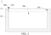
FIG. 3 is a second structural schematic view of the housing provided by some embodiments of the present disclosure. -
FIG. 4 is a third structural schematic view of the housing provided by some embodiments of the present disclosure. -
FIG. 5 is a fourth structural schematic view of the housing provided by some embodiments of the present disclosure. -
FIG. 6 is a fifth structural schematic view of the housing provided by some embodiments of the present disclosure. -
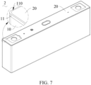
FIG. 7 is a schematic view of a three-dimensional structure of a housing assembly provided by some embodiments of the present disclosure. -
FIG. 8 is a structural exploded schematic view of the housing assembly provided by some embodiments of the present disclosure. -
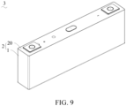
FIG. 9 is a schematic view of a three-dimensional structure of a battery provided by some embodiments of the present disclosure. -
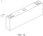
FIG. 10 is a structural exploded schematic view of the battery provided by some embodiments of the present disclosure. - In the figures:
- 1, housing; 10, insulating base body; 10a, accommodating cavity; 100, opening; 101, inner wall surface;
- 102, mounting side surface; 11, metal frame; 110, through hole; 12, first metal layer; 13, second metal layer;
- 2, housing assembly; 20, metal cover plate;
- 3, battery; 30, cell pack.
- As shown in
FIGS. 1 and2 , the present disclosure provides ahousing 1 including aninsulating base body 10 and ametal frame 11. Theinsulating base body 10 has anaccommodating cavity 10a. Theinsulating base body 10 has amounting side surface 102 provided with anopening 100 in communication with theaccommodating cavity 10a. Ametal frame 11 is provided around a circumferential portion of the opening 100 and is fixedly connected to theinsulating base body 10. A throughhole 110 in communication with theopening 100 is formed in themetal frame 11. Themetal frame 11 is used for connecting a metal cover plate, and the metal cover plate plugs the throughhole 110. - The
insulating base body 10 may have a thin housing structure to form the main structure of thehousing 1 having theaccommodation cavity 10a. Taking advantage of theinsulating base body 10 being less susceptible to chemical corrosion, the use safety of the battery including thehousing 1 is relatively high. In addition, the structural strength of thehousing 1 as a whole may be strengthened by providing ametal frame 11 along theopening 100, so that the structural strength of thehousing 1 may meet the use requirements. - Further, by providing the
metal frame 11 on theinsulating base body 10, the metal cover plate may be connected to themetal frame 11. In other words, by connecting the metal cover plate with themetal frame 11 both made of metal materials instead of fixing the metal cover plate to theinsulating base body 10 made of a non-metal material, so that the metal cover plate may be easily connected and fixed to themetal frame 11 by welding, the connection stability between the metal cover plate and themetal frame 11 is better, and the sealing performance of the metal cover plate sealing the throughhole 110 is also good. - In addition, since the density of the insulating material may be smaller than the density of the metal material, by forming the
housing 1 into a composite structure composed of theinsulating base body 10 and themetal frame 11, it is possible to achieve a more lightweight design for thehousing 1. - The insulating material may be a plastic material that may be molded by injection molding. Based on this, optionally, the
insulating base body 10 may be molded on the outer surface of themetal frame 11 by injection molding, thereby simultaneously completing the molding of theinsulating base body 10 and the connection between theinsulating base body 10 and themetal frame 11, so that the manufacturing process of thehousing 1 is simple, and the connection stability between theinsulating base body 10 and themetal frame 11 is good. - In other embodiments, the
metal frame 11 may be provided on theinsulating base body 10 by spraying or gluing. - Alternatively, the metal cover plate may be weakly charged by the cell of the battery, so that the
metal frame 11 connected to the metal cover plate is weakly charged to avoid chemical corrosion of themetal frame 11. - It should be noted that the "
metal frame 11 is provided around a circumferential portion of the opening 100" aforementioned includes, a case where themetal frame 11 surrounds the circumferential portion of theopening 100 and is provided outside theopening 100, a case where themetal frame 11 surrounds the circumferential portion of theopening 100 and is provided inside theopening 100, or a case where themetal frame 11 surrounds the circumferential portion of the opening 100 and a part of themetal frame 11 is provided inside theopening 100 and the remaining part of themetal frame 11 is provided outside the opening 100. - In some alternative embodiments, the
metal frame 11 may project from themounting side surface 102. Themetal frame 11 may surround the circumferential portion of theopening 100 and be provided outside theopening 100, or themetal frame 11 may surround the circumferential portion of theopening 100, and a part of themetal frame 11 may be provided inside theopening 100, and the remaining portion of themetal frame 11 may be provided outside theopening 100, so that the thickness of themetal frame 11 may be no less than the thickness of theinsulating base body 10, so that themetal frame 11 has greater structural strength, thereby making the structural strength of theentire housing 1 being greater. - As provided in the aforementioned technical solution, the
metal frame 11 may be weakly charged, but since the air pressure inside thehousing 1 will increase in condition of the battery being used for a period of time, and the cell of the battery will become thick, causing thehousing 1 to expand and deform, when a plurality of batteries are arranged at intervals, thehousings 1 of adjacent batteries may come into contact or even squeeze against each other. If the squeeze portion of thehousing 1 is provided with themetal frame 11 with electric charge, it will cause thehousings 1 of adjacent batteries to conduct electricity to each other and cause a fire. When thehousing 1 expands, it is usually the middle of the outer circumference of thehousing 1 that protrudes outward to the highest height and is most likely to come into contact with ahousing 1 of an adjacent cell. - A protrusion height of the
metal frame 11 protrudes from the mountingside surface 102 is h, and the higher the height h, the closer themetal frame 11 is to the middle of the outer periphery of thehousing 1 as a whole, and the greater the overall structural strength improvement effect of themetal frame 11 on theentire housing 1 is. When themetal frame 11 is not charged, the possibility of the metal frame contacting the powder falling from the cell pack is greater. When themetal frame 11 is charged, and thehousing 1 squeezes against ahousing 1 of an adjacent cell after expanding, the possibility of the adjacent metal frames 11 coming into contact and squeeze against each other is greater. However, the smaller the height h, the farther themetal frame 11 is from the middle of the outer periphery of thehousing 1 as a whole, and the smaller the overall structural strength improvement effect of themetal frame 11 on thehousing 1 is. When themetal frame 11 is not charged, the possibility of the metal frame contacting the powder falling from the cell pack is smaller. When themetal frame 11 is charged, and thehousing 1 squeezes against ahousing 1 of an adjacent cell after expanding, the possibility of the adjacent metal frames 11 coming into contact and squeeze against each other is smaller. Therefore, the height h may not be too large or too small. Based on this, the height h may optionally meet the requirement of 1 mm ≤ h ≤ 10 mm. For example, the height h may be 1 mm, 2 mm, 3 mm, 4 mm, 5 mm, 6 mm, 7 mm, 8 mm, 9 mm, or 10 mm, etc. - As shown in
FIG. 3 , since the overall thickness of thehousing 1 is thin, an area of the mountingside surface 102 of the insulatingbase body 10 is small, in other alternative embodiments, themetal frame 11 may be provided on theinner wall surface 101 of the insulatingbase body 10, and themetal frame 11 may surround the circumferential portion of theopening 100 and be provided inside theopening 100, so that the connection area between themetal frame 11 and the insulatingbase body 10 may be larger, and the connection stability between themetal frame 11 and the insulatingbase body 10 may be improved. Further, since themetal frame 11 is provided on theinner wall surface 101 of the insulatingbase body 10, even if themetal frame 11 is weakly charged, there is no case where thehousing 1 is electrically connected to theother housing 1 when thehousing 1 is pressed against theother housing 1. The use safety of thehousing 1 is good, and the installation range of themetal frame 11 is less limited. - As shown in
FIGS. 4 and5 , optionally, thehousing 1 may further include afirst metal layer 12. Thefirst metal layer 12 is provided on the outer surface of the insulatingbase body 10, so that the overall structural strength of thehousing 1 may be further improved by thefirst metal layer 12. In addition, the wear resistance of the outer surface of thehousing 1 may be improved, so as to protect the structure of the insulatingbase body 10 and reduce the possibility that the structure of the insulatingbase body 10 is damaged due to an external force during use. - Alternatively, the
first metal layer 12 may be formed on the outer surface of the insulatingbase body 10 by spraying or bonding, or thefirst metal layer 12 may be connected to the insulatingbase body 10 by injection molding on thefirst metal layer 12 to form the insulatingbase body 10. - Alternatively, the
first metal layer 12 may be connected to themetal frame 11 so as to be integrally connected, thereby reducing the number of parts included in thehousing 1, thereby simplifying the manufacturing and assembling process of thehousing 1. - In addition, the
metal frame 11 may surround the circumferential portion of theopening 100 and be provided outside theopening 100. In other words, themetal frame 11 is not connected and conducted to other conductive structures that may be located in theaccommodation cavity 10a except the metal cover plate, so that when the possibility of themetal frame 11 coming into contact with the electrolyte is small, themetal frame 11 may not be weakly charged, so that thefirst metal layer 12 connected to themetal frame 11 is also not charged, and the risk of fire caused by the adjacentfirst metal layers 12 conducting electricity may be avoided when thehousings 1 squeezes against an adjacent housing. - When the
metal frame 11 is weakly charged as described in the aforementioned technical solution, thefirst metal layer 12 and themetal frame 11 are provided at intervals to prevent thefirst metal layer 12 from being charged, thereby avoiding the risk of fire caused by the adjacentfirst metal layers 12 conducting electricity when thehousings 1 squeezes against the adjacent housing. - The insulating
base body 10 has a thickness t1. Since the insulatingbase body 10 may be protected by thefirst metal layer 12, the requirement for structural wear resistance of the insulatingbase body 10 is smaller, and the thickness t1 of the insulatingbase body 10 may be provided thinner. The larger the thickness t1 of the insulatingsubstrate 10, the thickness of thefirst metal layer 12 may be reduced while ensuring that the overall strength of thehousing 1 meets the use requirements, thereby achieving a more lightweight design for thehousing 1. Based on this, optionally, the thickness t1 may satisfy: 0.01 mm ≤ t1 ≤ 0.5 mm. For example, the thickness t1 may be 0.01 mm, 0.02 mm, 0.05 mm, 0.08 mm, 0.1 mm, 0.15 mm, 0.2 mm, 0.25 mm, 0.3 mm, 0.35 mm, 0.4 mm, 0.45 mm, or 0.5 mm, etc. - The
housing 1 may further include asecond metal layer 13 provided on theinner wall surface 101 of the insulatingbase body 10, and thesecond metal layer 13 is connected to themetal frame 11, so that the overall structural strength of thehousing 1 may be further improved by thesecond metal layer 13. In addition, since a part of the surface of thesecond metal layer 13 is formed as theinner wall surface 101 of a whole of thehousing 1, by connecting thesecond metal layer 13 to themetal frame 11, thesecond metal layer 13 and themetal frame 11 may be electrically conducted, and the metal cover plate may be weakly charged, so that themetal frame 11 and thesecond metal layer 13 may be weakly charged, so as to avoid chemical corrosion of thesecond metal layer 13. - In addition, the
first metal layer 12 is provided at an interval from themetal frame 11 to prevent thefirst metal layer 12 from being charged, so that when thehousing 1 and theadjacent housing 1 squeezes against each other, the risk of fire caused by the adjacentfirst metal layers 12 conducting electricity is avoided. - Alternatively, the
second metal layer 13 may be formed on theinner wall surface 101 of the insulatingbase body 10 by spraying or bonding, or thesecond metal layer 13 may be connected to the insulatingbase body 10 by injection molding on thesecond metal layer 13 to form the insulatingbase body 10. - Alternatively, the
second metal layer 13 may be integrally connected to themetal frame 11, thereby reducing the number of parts included in thehousing 1, thereby simplifying the manufacturing and assembling process of thehousing 1. - The
housing 1 has a thickness t2. The smaller the thickness t2, the smaller the overall structural strength of thehousing 1 is. The larger the thickness t2, the larger the space occupied by thehousing 1 is. Therefore, the thickness t2 may not be too small or too large. Based on this, the thickness t2 may optionally satisfy: 0.35 mm ≦ t2 ≦ 0. 8 mm, for example, the thickness t2 may be 0.35 mm, 0.4 mm, 0.45 mm, 0.5 mm, 0.6 mm, 0.65 mm, 0.7 mm, 0.75 mm, or 0.8 mm, etc. - In order to achieving a more lightweight design for a whole of the
housing 1, the thickness t1 of the insulatingbase body 10 may be greater, and the thickness of thefirst metal layer 12 may be smaller, or the total thickness of thefirst metal layer 12 and thesecond metal layer 13 may be smaller. But in order to avoid the overall thickness t2 of thehousing 1 too larger to cause the space occupied by thehousing 1 to be excessively large, the thickness t1 may not be excessively large. Based on this, the thickness t1 may satisfy: 0.3 mm ≤ t1 ≤ 0.5 mm, for example, the thickness t1 may be 0.3 mm, 0.32 mm, 0.34 mm, 0.35 mm, 0.36 mm, 0.38 mm, 0.4 mm, 0.42 mm, 0.44 mm, 0.45 mm, 0.46 mm, 0.48 mm, or 0.5 mm, etc. - In other embodiments, the
housing 1 may further include only thesecond metal layer 13 and does not include thefirst metal layer 12. The insulatingbase body 10 is further reinforced only from theinner wall surface 101 of the insulatingbase body 10, and the structural strength of thehousing 1 as a whole is further improved. - As shown in
FIGS. 7 and8 , the present disclosure provides ahousing assembly 2 including ametal cover plate 20. Thehousing assembly 2 further includes thehousing 1 as described in the aforementioned technical solutions. Themetal cover plate 20 is fixed to ametal frame 11 of thehousing 1 and seals a throughhole 110. Thehousing assembly 2 is provided with thehousing 1 as described in the aforementioned technical solutions, so that the use safety of a battery including thehousing assembly 2 is relatively high. Further, since themetal cover plate 20 and themetal frame 11 are both made of metal materials, it is convenient to fix themetal cover plate 20 to themetal frame 11 by welding. The connection stability between themetal cover plate 20 and themetal frame 11 is good, and the sealing performance of themetal cover plate 20 to seal the throughhole 110 is also good. - As shown in
FIGS. 9 and10 , the present disclosure provides abattery 3 including a cell pack 30. Thebattery 3 further includes thehousing assembly 2 provided in the aforementioned technical solutions. The cell pack 30 is provided in thehousing 1. For example, a whole of the cell pack 30 may be provided in theaccommodation cavity 10a, or a part of the cell pack 30 may be provided in theaccommodation cavity 10a, and the remaining part of the cell pack 30 extends from the opening 100 (seeFIG. 2 ) to be located between theopening 100 and the throughhole 110. Thebattery 3 may have higher safety in use by providing thehousing assembly 2 as described in the aforementioned technical solution.
Claims (11)
- A housing comprising:an insulating base body (10) comprising an accommodating cavity (10a), wherein the insulating base body (10a) comprises a mounting side surface (102) defining an opening (100) in communication with the accommodating cavity (10a); anda metal frame (11) provided around a circumferential portion of the opening (100) and fixedly connected to the insulating base body (10), wherein a through hole (110) in communication with the opening (100) is defined by the metal frame (11), the metal frame (11) is configured to be connected to a metal cover plate (20), and the metal cover plate (20) is configured to plug the through hole (110).
- The housing of claim 1, wherein the housing (1) further comprises a first metal layer (12) disposed on an outer surface of the insulating base body (10).
- The housing of claim 2, wherein the insulating base body (10) has a thickness t1, and t1 is greater than or equal to 0.01 millimeters and less than or equal to 0.5 millimeters.
- The housing of claim 2, wherein the metal frame (11) is disposed outside the opening (100), and the first metal layer (12) is connected to the metal frame (11).
- The housing of claim 2, wherein the housing (1) further comprises a second metal layer (13) disposed on an inner wall surface (101) of the insulating base body (10), and the second metal layer (13) is connected to the metal frame (11); and
the first metal layer (12) is provided at intervals from the metal frame (11). - The housing of claims 2, 4 or 5, wherein the insulating base body (10) has a thickness t1, t1 is greater than or equal to 0.3 millimeters and less than or equal to 0.5 millimeters, the housing (1) has a thickness t2, and t2 is greater than or equal to 0.35 millimeters and less than or equal to 0.8 millimeters.
- The housing of any one of claims 1 to 5, wherein the metal frame (11) projects from the mounting side surface (102).
- The housing of claim 7, wherein a protruding height of the metal frame (11) protruding from the mounting side surface (102) is h, and h is greater than or equal to 1 millimeter and less than or equal to 10 millimeters.
- The housing of any one of claims 1 to 5, wherein the metal frame (11) is disposed on an inner wall surface (101) of the insulating base body (10).
- A housing assembly, comprising a metal cover plate (20), wherein the housing assembly (2) further comprises the housing (1) in any one of claims 1 to 9, the metal frame (11) of the housing (1) is connected to the metal cover plate (20), and the metal cover plate (20) plugs the through hole (110).
- A battery, comprising a cell pack (30), wherein the battery (3) further comprises the housing assembly (2) in claim 10, the cell pack (30) is disposed within the housing (1).
Applications Claiming Priority (2)
| Application Number | Priority Date | Filing Date | Title |
|---|---|---|---|
| CN202321557431.9U CN220138540U (en) | 2023-06-19 | 2023-06-19 | Housings, housing components and batteries |
| PCT/CN2024/100126 WO2024260370A1 (en) | 2023-06-19 | 2024-06-19 | Housing, shell assembly, and battery |
Publications (2)
| Publication Number | Publication Date |
|---|---|
| EP4517979A1 true EP4517979A1 (en) | 2025-03-05 |
| EP4517979A4 EP4517979A4 (en) | 2025-10-22 |
Family
ID=88952219
Family Applications (1)
| Application Number | Title | Priority Date | Filing Date |
|---|---|---|---|
| EP24809533.3A Pending EP4517979A4 (en) | 2023-06-19 | 2024-06-19 | HOUSING, SHELL ASSEMBLY AND BATTERY |
Country Status (4)
| Country | Link |
|---|---|
| US (1) | US20250096379A1 (en) |
| EP (1) | EP4517979A4 (en) |
| CN (1) | CN220138540U (en) |
| WO (1) | WO2024260370A1 (en) |
Families Citing this family (1)
| Publication number | Priority date | Publication date | Assignee | Title |
|---|---|---|---|---|
| CN220138540U (en) * | 2023-06-19 | 2023-12-05 | 湖北亿纬动力有限公司 | Housings, housing components and batteries |
Family Cites Families (10)
| Publication number | Priority date | Publication date | Assignee | Title |
|---|---|---|---|---|
| JP4562301B2 (en) * | 2001-02-27 | 2010-10-13 | 京セラ株式会社 | Electronic component storage package |
| US7023078B2 (en) * | 2003-05-06 | 2006-04-04 | Seiko Instruments Inc. | Packages for communication devices |
| JP4361319B2 (en) * | 2003-06-05 | 2009-11-11 | セイコーインスツル株式会社 | Electrochemical cell and method for producing the same |
| JP4332037B2 (en) * | 2004-01-19 | 2009-09-16 | 京セラ株式会社 | Electronic component storage package and electronic device |
| JP4892180B2 (en) * | 2004-08-20 | 2012-03-07 | セイコーインスツル株式会社 | ELECTROCHEMICAL CELL, ITS MANUFACTURING METHOD, AND ITS VISION INSPECTION METHOD |
| JP4941653B2 (en) * | 2007-02-27 | 2012-05-30 | セイコーインスツル株式会社 | Method for producing electrochemical element |
| CN216085054U (en) * | 2021-07-01 | 2022-03-18 | 恒大新能源技术(深圳)有限公司 | Battery case and lithium ion battery |
| CN217903274U (en) * | 2022-08-12 | 2022-11-25 | 天宝电子(惠州)有限公司 | Battery pack structure of combined energy storage equipment |
| CN219144363U (en) * | 2022-12-28 | 2023-06-06 | 欣旺达电动汽车电池有限公司 | Battery and battery pack |
| CN220138540U (en) * | 2023-06-19 | 2023-12-05 | 湖北亿纬动力有限公司 | Housings, housing components and batteries |
-
2023
- 2023-06-19 CN CN202321557431.9U patent/CN220138540U/en active Active
-
2024
- 2024-06-19 WO PCT/CN2024/100126 patent/WO2024260370A1/en not_active Ceased
- 2024-06-19 EP EP24809533.3A patent/EP4517979A4/en active Pending
- 2024-11-29 US US18/964,340 patent/US20250096379A1/en active Pending
Also Published As
| Publication number | Publication date |
|---|---|
| WO2024260370A1 (en) | 2024-12-26 |
| CN220138540U (en) | 2023-12-05 |
| US20250096379A1 (en) | 2025-03-20 |
| EP4517979A4 (en) | 2025-10-22 |
Similar Documents
| Publication | Publication Date | Title |
|---|---|---|
| CN118213682A (en) | Top cap subassembly and secondary cell of secondary cell | |
| CN110752324A (en) | Sealing assembly and lithium ion battery | |
| CN216354452U (en) | Shell structure and battery | |
| EP4517979A1 (en) | Housing, shell assembly, and battery | |
| CN215451564U (en) | Battery case subassembly and lithium cell that has it | |
| CN214411343U (en) | Battery top cap structure and battery | |
| CN210668435U (en) | Batteries and Electronic Equipment | |
| CN218005070U (en) | Battery and battery module | |
| CN217334239U (en) | Battery and electronic device | |
| KR100839783B1 (en) | Secondary battery | |
| CN216085078U (en) | Lithium ion battery and application product thereof | |
| CN215771294U (en) | Lithium battery and mobile communication device having the same | |
| CN219677505U (en) | Battery and electronic equipment | |
| CN220209152U (en) | Energy sheet battery | |
| WO2023231680A1 (en) | Battery | |
| CN214226975U (en) | Button battery packaging structure and button battery | |
| CN221861889U (en) | Battery cell | |
| CN115425341A (en) | Winding type button battery with ruffle structure | |
| CN224191045U (en) | Cover plate structure, battery pack and electric equipment | |
| CN223401712U (en) | Battery housing assembly and power supply module | |
| CN223638468U (en) | Battery cells, batteries and electrical devices | |
| CN224191027U (en) | A core, a battery, a battery pack, and an electrical device. | |
| CN221486564U (en) | Secondary batteries and battery packs | |
| CN223712879U (en) | A casing and a battery | |
| CN224005994U (en) | Top cap subassembly, battery and consumer |
Legal Events
| Date | Code | Title | Description |
|---|---|---|---|
| STAA | Information on the status of an ep patent application or granted ep patent |
Free format text: STATUS: UNKNOWN |
|
| STAA | Information on the status of an ep patent application or granted ep patent |
Free format text: STATUS: THE INTERNATIONAL PUBLICATION HAS BEEN MADE |
|
| PUAI | Public reference made under article 153(3) epc to a published international application that has entered the european phase |
Free format text: ORIGINAL CODE: 0009012 |
|
| STAA | Information on the status of an ep patent application or granted ep patent |
Free format text: STATUS: REQUEST FOR EXAMINATION WAS MADE |
|
| 17P | Request for examination filed |
Effective date: 20241129 |
|
| AK | Designated contracting states |
Kind code of ref document: A1 Designated state(s): AL AT BE BG CH CY CZ DE DK EE ES FI FR GB GR HR HU IE IS IT LI LT LU LV MC ME MK MT NL NO PL PT RO RS SE SI SK SM TR |
|
| A4 | Supplementary search report drawn up and despatched |
Effective date: 20250923 |
|
| RIC1 | Information provided on ipc code assigned before grant |
Ipc: H01M 50/244 20210101AFI20250917BHEP Ipc: H01M 50/24 20210101ALI20250917BHEP Ipc: H01M 50/289 20210101ALI20250917BHEP Ipc: H01M 50/10 20210101ALI20250917BHEP Ipc: H01L 23/02 20060101ALI20250917BHEP Ipc: H01M 50/124 20210101ALI20250917BHEP Ipc: H01M 50/145 20210101ALI20250917BHEP Ipc: H01M 50/159 20210101ALI20250917BHEP Ipc: H01M 50/169 20210101ALI20250917BHEP |