EP4517963A2 - Battery pack - Google Patents
Battery pack Download PDFInfo
- Publication number
- EP4517963A2 EP4517963A2 EP24190045.5A EP24190045A EP4517963A2 EP 4517963 A2 EP4517963 A2 EP 4517963A2 EP 24190045 A EP24190045 A EP 24190045A EP 4517963 A2 EP4517963 A2 EP 4517963A2
- Authority
- EP
- European Patent Office
- Prior art keywords
- stack
- conductive member
- battery pack
- cover portion
- electrical apparatus
- Prior art date
- Legal status (The legal status is an assumption and is not a legal conclusion. Google has not performed a legal analysis and makes no representation as to the accuracy of the status listed.)
- Pending
Links
Images




Classifications
-
- H—ELECTRICITY
- H01—ELECTRIC ELEMENTS
- H01M—PROCESSES OR MEANS, e.g. BATTERIES, FOR THE DIRECT CONVERSION OF CHEMICAL ENERGY INTO ELECTRICAL ENERGY
- H01M50/00—Constructional details or processes of manufacture of the non-active parts of electrochemical cells other than fuel cells, e.g. hybrid cells
- H01M50/20—Mountings; Secondary casings or frames; Racks, modules or packs; Suspension devices; Shock absorbers; Transport or carrying devices; Holders
- H01M50/204—Racks, modules or packs for multiple batteries or multiple cells
- H01M50/207—Racks, modules or packs for multiple batteries or multiple cells characterised by their shape
- H01M50/209—Racks, modules or packs for multiple batteries or multiple cells characterised by their shape adapted for prismatic or rectangular cells
-
- H—ELECTRICITY
- H01—ELECTRIC ELEMENTS
- H01M—PROCESSES OR MEANS, e.g. BATTERIES, FOR THE DIRECT CONVERSION OF CHEMICAL ENERGY INTO ELECTRICAL ENERGY
- H01M50/00—Constructional details or processes of manufacture of the non-active parts of electrochemical cells other than fuel cells, e.g. hybrid cells
- H01M50/50—Current conducting connections for cells or batteries
- H01M50/502—Interconnectors for connecting terminals of adjacent batteries; Interconnectors for connecting cells outside a battery casing
- H01M50/503—Interconnectors for connecting terminals of adjacent batteries; Interconnectors for connecting cells outside a battery casing characterised by the shape of the interconnectors
-
- H—ELECTRICITY
- H01—ELECTRIC ELEMENTS
- H01M—PROCESSES OR MEANS, e.g. BATTERIES, FOR THE DIRECT CONVERSION OF CHEMICAL ENERGY INTO ELECTRICAL ENERGY
- H01M50/00—Constructional details or processes of manufacture of the non-active parts of electrochemical cells other than fuel cells, e.g. hybrid cells
- H01M50/50—Current conducting connections for cells or batteries
- H01M50/502—Interconnectors for connecting terminals of adjacent batteries; Interconnectors for connecting cells outside a battery casing
- H01M50/507—Interconnectors for connecting terminals of adjacent batteries; Interconnectors for connecting cells outside a battery casing comprising an arrangement of two or more busbars within a container structure, e.g. busbar modules
-
- H—ELECTRICITY
- H01—ELECTRIC ELEMENTS
- H01M—PROCESSES OR MEANS, e.g. BATTERIES, FOR THE DIRECT CONVERSION OF CHEMICAL ENERGY INTO ELECTRICAL ENERGY
- H01M10/00—Secondary cells; Manufacture thereof
- H01M10/05—Accumulators with non-aqueous electrolyte
- H01M10/058—Construction or manufacture
-
- H—ELECTRICITY
- H01—ELECTRIC ELEMENTS
- H01M—PROCESSES OR MEANS, e.g. BATTERIES, FOR THE DIRECT CONVERSION OF CHEMICAL ENERGY INTO ELECTRICAL ENERGY
- H01M50/00—Constructional details or processes of manufacture of the non-active parts of electrochemical cells other than fuel cells, e.g. hybrid cells
- H01M50/20—Mountings; Secondary casings or frames; Racks, modules or packs; Suspension devices; Shock absorbers; Transport or carrying devices; Holders
- H01M50/204—Racks, modules or packs for multiple batteries or multiple cells
-
- H—ELECTRICITY
- H01—ELECTRIC ELEMENTS
- H01M—PROCESSES OR MEANS, e.g. BATTERIES, FOR THE DIRECT CONVERSION OF CHEMICAL ENERGY INTO ELECTRICAL ENERGY
- H01M50/00—Constructional details or processes of manufacture of the non-active parts of electrochemical cells other than fuel cells, e.g. hybrid cells
- H01M50/20—Mountings; Secondary casings or frames; Racks, modules or packs; Suspension devices; Shock absorbers; Transport or carrying devices; Holders
- H01M50/271—Lids or covers for the racks or secondary casings
-
- H—ELECTRICITY
- H01—ELECTRIC ELEMENTS
- H01M—PROCESSES OR MEANS, e.g. BATTERIES, FOR THE DIRECT CONVERSION OF CHEMICAL ENERGY INTO ELECTRICAL ENERGY
- H01M50/00—Constructional details or processes of manufacture of the non-active parts of electrochemical cells other than fuel cells, e.g. hybrid cells
- H01M50/20—Mountings; Secondary casings or frames; Racks, modules or packs; Suspension devices; Shock absorbers; Transport or carrying devices; Holders
- H01M50/284—Mountings; Secondary casings or frames; Racks, modules or packs; Suspension devices; Shock absorbers; Transport or carrying devices; Holders with incorporated circuit boards, e.g. printed circuit boards [PCB]
-
- H—ELECTRICITY
- H01—ELECTRIC ELEMENTS
- H01M—PROCESSES OR MEANS, e.g. BATTERIES, FOR THE DIRECT CONVERSION OF CHEMICAL ENERGY INTO ELECTRICAL ENERGY
- H01M50/00—Constructional details or processes of manufacture of the non-active parts of electrochemical cells other than fuel cells, e.g. hybrid cells
- H01M50/50—Current conducting connections for cells or batteries
- H01M50/502—Interconnectors for connecting terminals of adjacent batteries; Interconnectors for connecting cells outside a battery casing
- H01M50/514—Methods for interconnecting adjacent batteries or cells
- H01M50/517—Methods for interconnecting adjacent batteries or cells by fixing means, e.g. screws, rivets or bolts
-
- H—ELECTRICITY
- H01—ELECTRIC ELEMENTS
- H01M—PROCESSES OR MEANS, e.g. BATTERIES, FOR THE DIRECT CONVERSION OF CHEMICAL ENERGY INTO ELECTRICAL ENERGY
- H01M50/00—Constructional details or processes of manufacture of the non-active parts of electrochemical cells other than fuel cells, e.g. hybrid cells
- H01M50/50—Current conducting connections for cells or batteries
- H01M50/502—Interconnectors for connecting terminals of adjacent batteries; Interconnectors for connecting cells outside a battery casing
- H01M50/521—Interconnectors for connecting terminals of adjacent batteries; Interconnectors for connecting cells outside a battery casing characterised by the material
- H01M50/522—Inorganic material
-
- H—ELECTRICITY
- H01—ELECTRIC ELEMENTS
- H01M—PROCESSES OR MEANS, e.g. BATTERIES, FOR THE DIRECT CONVERSION OF CHEMICAL ENERGY INTO ELECTRICAL ENERGY
- H01M2220/00—Batteries for particular applications
- H01M2220/20—Batteries in motive systems, e.g. vehicle, ship, plane
-
- Y—GENERAL TAGGING OF NEW TECHNOLOGICAL DEVELOPMENTS; GENERAL TAGGING OF CROSS-SECTIONAL TECHNOLOGIES SPANNING OVER SEVERAL SECTIONS OF THE IPC; TECHNICAL SUBJECTS COVERED BY FORMER USPC CROSS-REFERENCE ART COLLECTIONS [XRACs] AND DIGESTS
- Y02—TECHNOLOGIES OR APPLICATIONS FOR MITIGATION OR ADAPTATION AGAINST CLIMATE CHANGE
- Y02E—REDUCTION OF GREENHOUSE GAS [GHG] EMISSIONS, RELATED TO ENERGY GENERATION, TRANSMISSION OR DISTRIBUTION
- Y02E60/00—Enabling technologies; Technologies with a potential or indirect contribution to GHG emissions mitigation
- Y02E60/10—Energy storage using batteries
Definitions
- the present technology relates to a battery pack.
- WO 2021/123714 is a related art document that discloses a configuration of a battery pack.
- a plurality of busbars connecting a plurality of battery modules are disposed on an identical plane over the plurality of battery modules.
- a cell-to-pack structure of a battery pack has started to be employed, where a stack including a plurality of battery cells is stored in a case as it is without using any end plate or bind bar (module structure) for restraining the plurality of battery cells.
- a stack including a plurality of battery cells is stored in a case as it is without using any end plate or bind bar (module structure) for restraining the plurality of battery cells.
- the present technology has been devised to solve the above-described problem and is aimed at providing a battery pack employing the cell-to-pack structure, where the space inside the battery pack can be used effectively.
- the present technology provides the following battery pack.
- the terms “comprise”, “include”, and “have” are open-end terms. That is, when a certain configuration is included, a configuration other than the foregoing configuration may or may not be included.
- the term “battery” is not limited to a lithium ion battery but may include other batteries such as a nickel-metal hydride battery and a sodium ion battery.
- the term “electrode” may collectively represent a positive electrode and a negative electrode.
- the "battery pack" according to the present specification can be mounted on vehicles such as a hybrid electric vehicle (HEV), a plug-in hybrid electric vehicle (PHEV), and a battery electric vehicle (BEV).
- HEV hybrid electric vehicle
- PHEV plug-in hybrid electric vehicle
- BEV battery electric vehicle
- the use of the "battery pack” according to the present specification is not limited to the use in a vehicle.
- an X direction as a second direction is the direction in which a plurality of stacks and an electrical apparatus are arranged
- a Y direction as a first direction is the direction in which a plurality of battery cells are arranged
- a Z direction as a third direction is the direction in which a first conductive member and a second conductive member are arranged.
- the dimensional ratio of each configuration in the drawings may be changed from the actual dimensional ratio thereof.
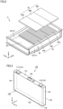
- Fig. 1 is a perspective view illustrating a configuration of a battery pack 1 according to Embodiment 1 of the present technology.
- Fig. 2 is a perspective view illustrating an internal structure of battery pack 1 according to Embodiment 1 of the present technology.
- a board member 60 is not illustrated, which is described later.
- battery pack 1 includes a stack 10, a case 20, a busbar module 30, a conductive member 40, and an electrical apparatus 50.
- Stack 10 includes a first stack 10A, a second stack 10B, and a third stack 10C.
- First stack 10A includes a plurality of first battery cells arranged in the first direction (the Y direction).
- Second stack 10B includes a plurality of second battery cells arranged in the first direction (the Y direction).
- Third stack 10C includes a plurality of third battery cells arranged in the first direction (the Y direction). The first battery cell, the second battery cell, and the third battery cell that are each a battery cell 100 (see Fig. 3 ) are described in detail later.
- Case 20 accommodates first stack 10A, second stack 10B, third stack 10C, and electrical apparatus 50.
- Case 20 includes a pair of side walls 21.
- the pair of side walls 21 include one side wall 22 and the other side wall 23.
- the pair of side walls 21 support first stack 10A, second stack 10B, and third stack 10C from both sides in the first direction (the Y direction).
- the one side wall 22 and the other side wall 23 directly support first stack 10A, second stack 10B, and third stack 10C from both sides in the Y direction.
- battery pack 1 employs a cell-to-pack structure where stack 10 including the plurality of battery cells is stored in case 20 as it is.
- Busbar module 30 is disposed over stack 10. Busbar module 30 electrically insulates stack 10 and another component disposed over stack 10. Busbar module 30 electrically connects the plurality of battery cells in stack 10 using inter-cell busbars, which are not illustrated.
- Busbar module 30 includes a first busbar module 30A disposed over first stack 10A, a second busbar module 30B disposed over second stack 10B, and a third busbar module 30C disposed over third stack 10C.
- Conductive member 40 is provided so as to electrically connect the stacks and electrically connect stack 10 and electrical apparatus 50.
- Conductive member 40 is made of copper for example.
- Conductive member 40 includes a plate-like first conductive member 400, a plate-like second conductive member 410, a plate-like third conductive member 420, and a plate-like fourth conductive member 430.
- First conductive member 400 and second conductive member 410 are disposed near the one side wall 22 included in the pair of side walls 21.
- First conductive member 400 extends in the second direction (the X direction).
- Second conductive member 410 bends and extends along the second direction (the X direction).
- First conductive member 400 electrically connects first stack 10A and second stack 10B.
- Second conductive member 410 electrically connects third stack 10C and electrical apparatus 50.
- Third conductive member 420 and fourth conductive member 430 are disposed near the other side wall 23 included in the pair of side walls 21. Third conductive member 420 bends and extends along the X direction. Fourth conductive member 430 extends in the X direction.
- Third conductive member 420 electrically connects first stack 10A and electrical apparatus 50.
- Fourth conductive member 430 electrically connects second stack 10B and third stack 10C.
- Electrical apparatus 50 is, for example, a junction box for electrically connecting stack 10 and an external device of battery pack 1. Electrical apparatus 50 is electrically connected to first stack 10A, second stack 10B, and third stack 10C. Electrical apparatus 50 is not limited to a junction box but may be a fourth stack in which a plurality of battery cells are arranged in the Y direction or may be a terminal or a terminal box for connecting battery pack 1 and the external device.
- first stack 10A In the second direction (the X direction) orthogonal to the first direction (the Y direction), electrical apparatus 50, first stack 10A, second stack 10B, and third stack 10C are arranged in this order.
- Fig. 3 is a perspective view illustrating a configuration of battery cell 100 according to Embodiment 1 of the present technology.
- battery cell 100 according to the present embodiment includes an electrode terminal 110, a housing 120, and a gas discharge valve 130.
- Electrode terminal 110 is formed on housing 120. Electrode terminal 110 includes a positive electrode terminal 111 and a negative electrode terminal 112. Positive electrode terminal 111 and negative electrode terminal 112 are arranged in the X direction.
- Housing 120 is a container that accommodates an electrode assembly and an electrolyte solution, which are not illustrated. Housing 120 has a substantially rectangular parallelepiped shape. Housing 120 is made of aluminum, an aluminum alloy, iron, an iron alloy such as stainless steel, or the like.
- Housing 120 includes a sealing plate 121, a bottom surface 122, a pair of long side walls 123, and a pair of short side walls 124.
- Sealing plate 121 forms the upper surface of housing 120. Electrode terminal 110 is disposed on sealing plate 121. Bottom surface 122 is opposite to sealing plate 121 in the Z direction.
- the pair of long side walls 123 and the pair of short side walls 124 form the side surface of housing 120.
- the pair of long side walls 123 and the pair of short side walls 124 are orthogonal to each of sealing plate 121 and bottom surface 122.
- the pair of long side walls 123 are opposite to each other in the Y direction with the electrode assembly interposed therebetween.
- the pair of short side walls 124 are opposite to each other in the X direction with the electrode assembly interposed therebetween.
- Each of the pair of long side walls 123 has a larger area than that of each of the pair of short side walls 124.
- Gas discharge valve 130 is fractured when the pressure inside housing 120 becomes equal to or exceeds a predetermined value. Accordingly, the gas in housing 120 is discharged out of housing 120.
- Fig. 4 is a perspective view illustrating a positional relation between first conductive member 400 and second conductive member 410.
- second conductive member 410 includes a first bending portion 411 and a second bending portion 412.
- First bending portion 411 is located on the third stack 10C side relative to the center of second conductive member 410 in the X direction.
- Second bending portion 412 is located on the electrical apparatus 50 side relative to the center of second conductive member 410 in the X direction.
- Second conductive member 410 bends upward in the Z direction in first bending portion 411 from third stack 10C toward electrical apparatus 50. Further, second conductive member 410 bends downward in the Z direction in second bending portion 412 from third stack 10C toward electrical apparatus 50.
- First conductive member 400 is disposed between first bending portion 411 and second bending portion 412 of second conductive member 410 in the X direction. Accordingly, first conductive member 400 and second conductive member 410 overlap each other in the third direction (the Z direction) orthogonal to the first direction (the Y direction) and the second direction (the X direction). In the present embodiment, first conductive member 400 is disposed below second conductive member 410 in the Z direction.
- Second conductive member 410 gains a three-dimensional shape by including first bending portion 411 and second bending portion 412.
- a level difference in the Z direction may be caused by a positional difference in the Z direction between the respective upper surfaces of second busbar module 30B and third busbar module 30C and the upper surface of electrical apparatus 50.
- second conductive member 410 is easily adapted to the level difference by changing the bending angles of first bending portion 411 and second bending portion 412 as desired.
- Second conductive member 410 is formed by, for example, stamping such as pressing. If the first conductive member and the second conductive member are disposed on an identical plane on stack 10, the second conductive member extends in a plurality of directions along an X-Y plane. The material other than the portion that constitutes the second conductive member when the second conductive member is formed is to be discarded. In contrast, second conductive member 410 according to the present embodiment is made of a straight material that extends in the X direction in a view in the Z direction. Thus, the portion of the material to be discarded at the time of forming second conductive member 410 is reduced. As a result, yield at the time of forming second conductive member 410 is enhanced.
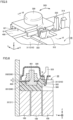
- Fig. 5 is a perspective view illustrating a configuration of a cover portion 320 included in busbar module 30.
- Fig. 6 is a cross sectional view illustrating a configuration around cover portion 320 in Fig. 5 , which is taken along the direction of a line with arrows VI-VI.
- busbar module 30 includes a plate member 300, a cover member 310, and a fastening member 330.
- Plate member 300 is a plate-like member, which is provided on battery cell 100 and has electrical insulation properties. Fastening member 330, the inter-cell busbars, and the like are disposed over plate member 300.
- Cover member 310 covers fastening member 330, the inter-cell busbars, and the like.
- Cover member 310 includes a main body portion 311, cover portion 320, and a holding mechanism.
- Main body portion 311 mainly covers the inter-cell busbars and the like.
- Cover portion 320 covers at least part of first conductive member 400 and fastening member 330. Cover portion 320 is disposed on the inner side of an opening portion 312 provided in main body portion 311.
- Cover portion 320 includes a depressed portion 321, an operation portion 322, and a hinge portion (not illustrated).
- First conductive member 400 is inserted through depressed portion 321.
- Operation portion 322 is provided opposite the one side wall 22 in relation to cover portion 320 in the Y direction. With operation portion 322, cover portion 320 can be opened and closed relative to main body portion 311.
- the hinge portion is located opposite first conductive member 400 in relation to fastening member 330 in the X direction. The hinge portion allows cover portion 320 to rotate (in a direction DR1 in Fig. 5 ) about an axis in the first direction when cover portion 320 is opened and closed.
- the holding mechanism holds cover portion 320 in a state of being open relative to main body portion 311.
- the holding mechanism includes a protruding portion 323 and a claw portion 314.
- Protruding portion 323 is disposed on cover portion 320.
- Protruding portion 323 extends in one direction and is elastically deformable.
- Claw portion 314 is disposed on main body portion 311.
- Protruding portion 323 can engage with claw portion 314. Through elastic deformation of protruding portion 323 and engagement of protruding portion 323 and claw portion 314, cover portion 320 can be held in the state of being open relative to main body portion 311.
- Fastening member 330 fastens first conductive member 400 to first stack 10A and second stack 10B.
- Fastening member 330 according to the present embodiment includes a bolt member 331 and a nut member 332.
- Bolt member 331 is inserted into a hole 401 of first conductive member 400.
- Bolt member 331 is screwed into nut member 332 in the state in which first conductive member 400 is disposed between bolt member 331 and nut member 332.
- second conductive member 410 and cover portion 320 overlap each other in the third direction (the Z direction).
- Cover portion 320 is located between fastening member 330 and second conductive member 410, and can thus prevent interference between fastening member 330 and second conductive member 410.
- cover portion 320 can move in the third direction (the Z direction) to an extent corresponding to gap G. Cover portion 320 can abut on second conductive member 410.
- Fig. 7 is a perspective view illustrating a state in which first conductive member 400 is fixed by a fixing portion 315 provided on second busbar module 30B.
- Fig. 7 illustrates the state in which first conductive member 400 included in conductive member 40 is fixed.
- cover member 310 includes fixing portion 315.
- Fixing portion 315 can fix first conductive member 400 on second busbar module 30B.
- fixing portion 315 has a structure in which a pair of hooks face each other. First conductive member 400 is inserted between the pair of hooks. Respective ends of the pair of hooks elastically deform and the gap between the pair of hooks increases, and after the insertion of first conductive member 400, the pair of hooks return to their original positions from the elastic deformation. The respective ends of the pair of hooks abut on the upper surface of first conductive member 400. Accordingly, first conductive member 400 is fixed by fixing portion 315.
- a guide member 316 is provided on both sides of fixing portion 315 in the X direction.
- Guide member 316 fixes first conductive member 400 in the direction orthogonal to the direction in which first conductive member 400 extends.
- Fixing portion 315 determines the position, in the Z direction, of first conductive member 400 and guide member 316 determines the position, in the Y direction, of first conductive member 400.
- Conductive member 40 other than first conductive member 400, which includes second conductive member 410, can also be fixed by fixing portion 315 on busbar module 30.
- Fixing portion 315 may determine the respective positions, in both of the Z direction and the Y direction, of conductive member 40.
- Fig. 8 is a perspective view illustrating a configuration of board member 60 included in battery pack 1 according to Embodiment 1 of the present technology.
- Fig. 9 is a cross sectional view illustrating a configuration near board member 60 in Fig. 8 , which is taken along the direction of a line with arrows IX-IX.
- battery pack 1 further includes board member 60.
- Board member 60 senses the temperature of each of the plurality of battery cells 100, for example, and controls the current value and the like.
- Board member 60 includes a control board 600 and a board cover portion 610.
- control board 600 is disposed at least over first stack 10A included in first stack 10A, second stack 10B, and third stack 10C.
- control board 600 according to the present embodiment is disposed only over first stack 10A with first busbar module 30A interposed therebetween.
- Board cover portion 610 has electrical insulation properties. Board cover portion 610 covers control board 600 in the third direction (the Z direction). Board cover portion 610 includes an extended-surface portion 611 and a folded portion 612.
- Extended-surface portion 611 is a portion that is extended, on the one side wall 22 side in the Y direction, from an end portion of the upper surface of board cover portion 610 so as to cover second conductive member 410.
- Folded portion 612 is a portion that is folded at an end portion of extended-surface portion 611 in the Y direction so as to be positioned on the lower surface side of second conductive member 410 in the Z direction.
- Extended-surface portion 611 and folded portion 612 support second conductive member 410. Accordingly, board cover portion 610 supports second conductive member 410. Board cover portion 610 having electrical insulation properties enables it to alleviate shaking of second conductive member 410 while ensuring electrical insulation.
- first conductive member 400 and second conductive member 410 overlap each other in the third direction (the Z direction) and accordingly, the occupancy area of conductive member 40 above stack 10 in a view in the Z direction can be decreased in comparison with the case where the first conductive member and the second conductive member are disposed on an identical plane on stack 10. As a result, space for disposing a component other than conductive member 40 can be reserved above stack 10 and thus, the space inside battery pack 1 can be used effectively.
- cover portion 320 is disposed between first conductive member 400 and second conductive member 410 and accordingly, interference between first conductive member 400 and second conductive member 410 can be inhibited.
- cover portion 320 In battery pack 1 according to Embodiment 1 of the present technology, upward and downward movements of cover portion 320 in the Z direction are enabled by gap G being present inside cover portion 320 relative to first conductive member 400 and fastening member 330. Accordingly, when second conductive member 410 shakes, cover portion 320 can absorb the shaking of second conductive member 410 by causing second conductive member 410 to abut on cover portion 320.
- a structure resistant to shaking can be achieved by fixing conductive member 40 with fixing portion 315 of cover member 310 when first conductive member 400 and second conductive member 410 are disposed so as to overlap each other in the Z direction.
- first conductive member 400 and second conductive member 410 are disposed so as to overlap each other in the Z direction while board cover portion 610 of board member 60 supports second conductive member 410, and even when second conductive member 410 shakes, the shaking of second conductive member 410 can be alleviated.
- first conductive member 400 and second conductive member 410 are each provided so as to extend in the second direction (the X direction). Accordingly, the respective lengths of first conductive member 400 and second conductive member 410 can be reduced and an upper space inside battery pack 1 can be used more effectively in comparison with the case where first conductive member 400 and second conductive member 410 are each disposed so as to be inclined from the X direction.
- Battery pack 1 according to Embodiment 2 is described below.
- Battery pack 1 according to Embodiment 2 is different from battery pack 1 according to Embodiment 1 of the present technology in the connection structure between the first conductive member and the stack, and the same features as those of battery pack 1 according to Embodiment 1 of the present technology are not described repeatedly.
- Fig. 10 is a perspective view illustrating a configuration of a first conductive member 400A included in battery pack 1 according to Embodiment 2 of the present technology.
- first conductive member 400A As illustrated in Fig. 10 , first conductive member 400A according to the present embodiment is connected to a stack 10 by welding.
- first conductive member 400A and second conductive member 410 overlap each other in the third direction (the Z direction) and accordingly, the occupancy area of the conductive member above stack 10 in a view in the Z direction can be decreased in comparison with the case where the first conductive member and the second conductive member are disposed on an identical plane on stack 10. As a result, space for disposing a component other than the conductive member can be reserved above stack 10 and thus, the space inside the battery pack can be used effectively.
Landscapes
- Chemical & Material Sciences (AREA)
- Chemical Kinetics & Catalysis (AREA)
- Electrochemistry (AREA)
- General Chemical & Material Sciences (AREA)
- Engineering & Computer Science (AREA)
- Manufacturing & Machinery (AREA)
- Inorganic Chemistry (AREA)
- Battery Mounting, Suspending (AREA)
- Connection Of Batteries Or Terminals (AREA)
Abstract
Description
- This nonprovisional application is based on
Japanese Patent Application No. 2023-139531 filed on August 30, 2023 - The present technology relates to a battery pack.
-
WO 2021/123714 is a related art document that discloses a configuration of a battery pack. In the configuration of the battery pack disclosed inWO 2021/123714 , a plurality of busbars connecting a plurality of battery modules are disposed on an identical plane over the plurality of battery modules. - A cell-to-pack structure of a battery pack has started to be employed, where a stack including a plurality of battery cells is stored in a case as it is without using any end plate or bind bar (module structure) for restraining the plurality of battery cells. When the configuration of the busbars included in the battery pack described in
WO 2021/123714 is applied to a battery pack employing the cell-to-pack structure, the space inside the battery pack can be used more effectively in order to increase energy density. - The present technology has been devised to solve the above-described problem and is aimed at providing a battery pack employing the cell-to-pack structure, where the space inside the battery pack can be used effectively.
- The present technology provides the following battery pack.
- [1] A battery pack comprising:
- a first stack including a plurality of first battery cells arranged in a first direction;
- a second stack including a plurality of second battery cells arranged in the first direction;
- a third stack including a plurality of third battery cells arranged in the first direction;
- an electrical apparatus electrically connected to the first stack, the second stack, and the third stack;
- a case accommodating the first stack, the second stack, the third stack, and the electrical apparatus;
- a plate-like first conductive member electrically connecting the first stack and the second stack; and
- a plate-like second conductive member electrically connecting the third stack and the electrical apparatus, wherein
- the case includes a pair of side walls supporting the first stack, the second stack, and the third stack from both sides in the first direction,
- the electrical apparatus, the first stack, the second stack, and the third stack are arranged in this order in a second direction orthogonal to the first direction, and
- the first conductive member and the second conductive member overlap each other in a third direction orthogonal to the first direction and the second direction.
- [2] The battery pack according to [1], further comprising
- a busbar module disposed over the first stack, the second stack, and the third stack, wherein
- the busbar module includes a fastening member and a cover member, the fastening member fastening the first conductive member to the first stack and the second stack, the cover member including a cover portion covering at least part of the first conductive member and the fastening member, and
- the second conductive member and the cover portion overlap each other in the third direction.
- [3] The battery pack according to [2], wherein
- a gap is present inside the cover portion relative to the at least part of the first conductive member and the fastening member, and
- the cover portion is movable to an extent corresponding to the gap and abuttable on the second conductive member in the third direction.
- [4] The battery pack according to [2] or [3], wherein
the cover member includes a fixing portion capable of fixing the first conductive member and the second conductive member over the busbar module. - [5] The battery pack according to any one of [1] to [4], further comprising:
- a control board disposed, in the third direction, at least over the first stack included in the first stack, the second stack, and the third stack; and
- a board cover portion covering the control board in the third direction, wherein
- the board cover portion supports the second conductive member.
- [6] The battery pack according to any one of [1] to [5], wherein
the first conductive member and the second conductive member each extend in the second direction. - The foregoing and other objects, features, aspects, and advantages of the present invention will become apparent from the following detailed description on the present invention, which will be understood in conjunction with the accompanying drawings.
-
-
Fig. 1 is a perspective view illustrating a configuration of a battery pack according to Embodiment 1 of the present technology. -
Fig. 2 is a perspective view illustrating an internal structure of the battery pack according toEmbodiment 1 of the present technology. -
Fig. 3 is a perspective view illustrating a configuration of a battery cell according toEmbodiment 1 of the present technology. -
Fig. 4 is a perspective view illustrating a positional relation between a first conductive member and a second conductive member. -
Fig. 5 is a perspective view illustrating a configuration of a cover portion included in a busbar module. -
Fig. 6 is a cross sectional view illustrating a configuration around the cover portion inFig. 5 , which is taken along the direction of a line with arrows VI-VI. -
Fig. 7 is a perspective view illustrating a state in which a conductive member is fixed by a fixing portion provided on the busbar module. -
Fig. 8 is a perspective view illustrating a configuration of a board member included in the battery pack according to Embodiment 1 of the present technology. -
Fig. 9 is a cross sectional view illustrating a configuration near the board member inFig. 8 , which is taken along the direction of a line with arrows IX-IX. -
Fig. 10 is a perspective view illustrating a configuration of a conductive member included in a battery pack according to Embodiment 2 of the present technology. - Embodiments of the present technology are described below. The same or corresponding portions are denoted by the same reference characters, and may not be described repeatedly.
- In the embodiments described below, when reference is made to a number, an amount, and the like, the scope of the present technology is not necessarily limited to the number, the amount, and the like unless otherwise stated particularly. Further, in the embodiments described below, each component is not necessarily essential to the present technology unless otherwise stated particularly. Further, the present technology is not limited to one that necessarily exhibits all the functions and effects mentioned in the present embodiments.
- In the present specification, the terms "comprise", "include", and "have" are open-end terms. That is, when a certain configuration is included, a configuration other than the foregoing configuration may or may not be included.
- Also, in the present specification, when geometric terms and terms representing positional/directional relations are used, for example, when terms such as "parallel", "orthogonal", "obliquely at 45°", "coaxial", and "along" are used, these terms tolerate manufacturing errors or slight fluctuations. In the present specification, when terms representing relative positional relations such as "upper side" and "lower side" are used, each of these terms is used to indicate a relative positional relation in one state, and the relative positional relation may be reversed or turned at any angle in accordance with an installation direction of each mechanism (by reversing the entire mechanism upside down for example).
- In the present specification, the term "battery" is not limited to a lithium ion battery but may include other batteries such as a nickel-metal hydride battery and a sodium ion battery. In the present specification, the term "electrode" may collectively represent a positive electrode and a negative electrode.
- Further, the "battery pack" according to the present specification can be mounted on vehicles such as a hybrid electric vehicle (HEV), a plug-in hybrid electric vehicle (PHEV), and a battery electric vehicle (BEV). The use of the "battery pack" according to the present specification is not limited to the use in a vehicle.
- In the drawings, an X direction as a second direction is the direction in which a plurality of stacks and an electrical apparatus are arranged, a Y direction as a first direction is the direction in which a plurality of battery cells are arranged, and a Z direction as a third direction is the direction in which a first conductive member and a second conductive member are arranged. To facilitate understanding of the present technology, the dimensional ratio of each configuration in the drawings may be changed from the actual dimensional ratio thereof.
-
Fig. 1 is a perspective view illustrating a configuration of abattery pack 1 according toEmbodiment 1 of the present technology.Fig. 2 is a perspective view illustrating an internal structure ofbattery pack 1 according toEmbodiment 1 of the present technology. InFigs. 1 and2 , aboard member 60 is not illustrated, which is described later. - As illustrated in
Figs. 1 and2 ,battery pack 1 according to the present embodiment includes astack 10, acase 20, abusbar module 30, aconductive member 40, and anelectrical apparatus 50. -
Stack 10 includes afirst stack 10A, asecond stack 10B, and athird stack 10C.First stack 10A includes a plurality of first battery cells arranged in the first direction (the Y direction).Second stack 10B includes a plurality of second battery cells arranged in the first direction (the Y direction).Third stack 10C includes a plurality of third battery cells arranged in the first direction (the Y direction). The first battery cell, the second battery cell, and the third battery cell that are each a battery cell 100 (seeFig. 3 ) are described in detail later. -
Case 20 accommodatesfirst stack 10A,second stack 10B,third stack 10C, andelectrical apparatus 50. -
Case 20 includes a pair ofside walls 21. The pair ofside walls 21 include oneside wall 22 and theother side wall 23. - The pair of
side walls 21 supportfirst stack 10A,second stack 10B, andthird stack 10C from both sides in the first direction (the Y direction). In the present embodiment, the oneside wall 22 and theother side wall 23 directly supportfirst stack 10A,second stack 10B, andthird stack 10C from both sides in the Y direction. Thus,battery pack 1 according to the present embodiment employs a cell-to-pack structure wherestack 10 including the plurality of battery cells is stored incase 20 as it is. -
Busbar module 30 is disposed overstack 10.Busbar module 30 electrically insulatesstack 10 and another component disposed overstack 10.Busbar module 30 electrically connects the plurality of battery cells instack 10 using inter-cell busbars, which are not illustrated. -
Busbar module 30 includes afirst busbar module 30A disposed overfirst stack 10A, asecond busbar module 30B disposed oversecond stack 10B, and athird busbar module 30C disposed overthird stack 10C. -
Conductive member 40 is provided so as to electrically connect the stacks and electrically connectstack 10 andelectrical apparatus 50.Conductive member 40 is made of copper for example. -
Conductive member 40 includes a plate-like firstconductive member 400, a plate-like secondconductive member 410, a plate-like thirdconductive member 420, and a plate-like fourthconductive member 430. - First
conductive member 400 and secondconductive member 410 are disposed near the oneside wall 22 included in the pair ofside walls 21. Firstconductive member 400 extends in the second direction (the X direction). Secondconductive member 410 bends and extends along the second direction (the X direction). - First
conductive member 400 electrically connectsfirst stack 10A andsecond stack 10B. Secondconductive member 410 electrically connectsthird stack 10C andelectrical apparatus 50. - Third
conductive member 420 and fourthconductive member 430 are disposed near theother side wall 23 included in the pair ofside walls 21. Thirdconductive member 420 bends and extends along the X direction. Fourthconductive member 430 extends in the X direction. - Third
conductive member 420 electrically connectsfirst stack 10A andelectrical apparatus 50. Fourthconductive member 430 electrically connectssecond stack 10B andthird stack 10C. -
Electrical apparatus 50 is, for example, a junction box for electrically connectingstack 10 and an external device ofbattery pack 1.Electrical apparatus 50 is electrically connected tofirst stack 10A,second stack 10B, andthird stack 10C.Electrical apparatus 50 is not limited to a junction box but may be a fourth stack in which a plurality of battery cells are arranged in the Y direction or may be a terminal or a terminal box for connectingbattery pack 1 and the external device. - In the second direction (the X direction) orthogonal to the first direction (the Y direction),
electrical apparatus 50,first stack 10A,second stack 10B, andthird stack 10C are arranged in this order. - In
battery pack 1 according to the present embodiment, current flows throughelectrical apparatus 50, thirdconductive member 420,first stack 10A, firstconductive member 400,second stack 10B, fourthconductive member 430,third stack 10C, secondconductive member 410, andelectrical apparatus 50 in this order. -
Fig. 3 is a perspective view illustrating a configuration ofbattery cell 100 according toEmbodiment 1 of the present technology. As illustrated inFig. 3 ,battery cell 100 according to the present embodiment includes anelectrode terminal 110, ahousing 120, and agas discharge valve 130. -
Electrode terminal 110 is formed onhousing 120.Electrode terminal 110 includes apositive electrode terminal 111 and anegative electrode terminal 112.Positive electrode terminal 111 andnegative electrode terminal 112 are arranged in the X direction. -
Housing 120 is a container that accommodates an electrode assembly and an electrolyte solution, which are not illustrated.Housing 120 has a substantially rectangular parallelepiped shape.Housing 120 is made of aluminum, an aluminum alloy, iron, an iron alloy such as stainless steel, or the like. -
Housing 120 includes a sealingplate 121, abottom surface 122, a pair oflong side walls 123, and a pair ofshort side walls 124. -
Sealing plate 121 forms the upper surface ofhousing 120.Electrode terminal 110 is disposed on sealingplate 121.Bottom surface 122 is opposite to sealingplate 121 in the Z direction. - The pair of
long side walls 123 and the pair ofshort side walls 124 form the side surface ofhousing 120. The pair oflong side walls 123 and the pair ofshort side walls 124 are orthogonal to each of sealingplate 121 andbottom surface 122. The pair oflong side walls 123 are opposite to each other in the Y direction with the electrode assembly interposed therebetween. The pair ofshort side walls 124 are opposite to each other in the X direction with the electrode assembly interposed therebetween. Each of the pair oflong side walls 123 has a larger area than that of each of the pair ofshort side walls 124. -
Gas discharge valve 130 is fractured when the pressure insidehousing 120 becomes equal to or exceeds a predetermined value. Accordingly, the gas inhousing 120 is discharged out ofhousing 120. -
Fig. 4 is a perspective view illustrating a positional relation between firstconductive member 400 and secondconductive member 410. As illustrated inFig. 4 , secondconductive member 410 includes afirst bending portion 411 and asecond bending portion 412. - First bending
portion 411 is located on thethird stack 10C side relative to the center of secondconductive member 410 in the X direction.Second bending portion 412 is located on theelectrical apparatus 50 side relative to the center of secondconductive member 410 in the X direction. - Second
conductive member 410 bends upward in the Z direction infirst bending portion 411 fromthird stack 10C towardelectrical apparatus 50. Further, secondconductive member 410 bends downward in the Z direction insecond bending portion 412 fromthird stack 10C towardelectrical apparatus 50. - First
conductive member 400 is disposed between first bendingportion 411 andsecond bending portion 412 of secondconductive member 410 in the X direction. Accordingly, firstconductive member 400 and secondconductive member 410 overlap each other in the third direction (the Z direction) orthogonal to the first direction (the Y direction) and the second direction (the X direction). In the present embodiment, firstconductive member 400 is disposed below secondconductive member 410 in the Z direction. - Second
conductive member 410 gains a three-dimensional shape by includingfirst bending portion 411 andsecond bending portion 412. A level difference in the Z direction may be caused by a positional difference in the Z direction between the respective upper surfaces ofsecond busbar module 30B andthird busbar module 30C and the upper surface ofelectrical apparatus 50. In this case, secondconductive member 410 is easily adapted to the level difference by changing the bending angles offirst bending portion 411 andsecond bending portion 412 as desired. - Second
conductive member 410 is formed by, for example, stamping such as pressing. If the first conductive member and the second conductive member are disposed on an identical plane onstack 10, the second conductive member extends in a plurality of directions along an X-Y plane. The material other than the portion that constitutes the second conductive member when the second conductive member is formed is to be discarded. In contrast, secondconductive member 410 according to the present embodiment is made of a straight material that extends in the X direction in a view in the Z direction. Thus, the portion of the material to be discarded at the time of forming secondconductive member 410 is reduced. As a result, yield at the time of forming secondconductive member 410 is enhanced. -
Fig. 5 is a perspective view illustrating a configuration of acover portion 320 included inbusbar module 30.Fig. 6 is a cross sectional view illustrating a configuration aroundcover portion 320 inFig. 5 , which is taken along the direction of a line with arrows VI-VI. - As illustrated in
Figs. 4 to 6 ,busbar module 30 includes aplate member 300, acover member 310, and afastening member 330. -
Plate member 300 is a plate-like member, which is provided onbattery cell 100 and has electrical insulation properties. Fasteningmember 330, the inter-cell busbars, and the like are disposed overplate member 300. -
Cover member 310 coversfastening member 330, the inter-cell busbars, and the like.Cover member 310 includes amain body portion 311,cover portion 320, and a holding mechanism.Main body portion 311 mainly covers the inter-cell busbars and the like. -
Cover portion 320 covers at least part of firstconductive member 400 andfastening member 330.Cover portion 320 is disposed on the inner side of anopening portion 312 provided inmain body portion 311. -
Cover portion 320 includes adepressed portion 321, anoperation portion 322, and a hinge portion (not illustrated). Firstconductive member 400 is inserted throughdepressed portion 321.Operation portion 322 is provided opposite the oneside wall 22 in relation to coverportion 320 in the Y direction. Withoperation portion 322,cover portion 320 can be opened and closed relative tomain body portion 311. The hinge portion is located opposite firstconductive member 400 in relation to fasteningmember 330 in the X direction. The hinge portion allowscover portion 320 to rotate (in a direction DR1 inFig. 5 ) about an axis in the first direction whencover portion 320 is opened and closed. - The holding mechanism holds
cover portion 320 in a state of being open relative tomain body portion 311. The holding mechanism includes a protrudingportion 323 and aclaw portion 314. Protrudingportion 323 is disposed oncover portion 320. Protrudingportion 323 extends in one direction and is elastically deformable.Claw portion 314 is disposed onmain body portion 311. Protrudingportion 323 can engage withclaw portion 314. Through elastic deformation of protrudingportion 323 and engagement of protrudingportion 323 andclaw portion 314,cover portion 320 can be held in the state of being open relative tomain body portion 311. - Fastening
member 330 fastens firstconductive member 400 tofirst stack 10A andsecond stack 10B. Fasteningmember 330 according to the present embodiment includes abolt member 331 and anut member 332.Bolt member 331 is inserted into ahole 401 of firstconductive member 400.Bolt member 331 is screwed intonut member 332 in the state in which firstconductive member 400 is disposed betweenbolt member 331 andnut member 332. - As illustrated in
Fig. 4 , secondconductive member 410 andcover portion 320 overlap each other in the third direction (the Z direction).Cover portion 320 is located betweenfastening member 330 and secondconductive member 410, and can thus prevent interference betweenfastening member 330 and secondconductive member 410. - As illustrated in
Figs. 5 and 6 , a gap G is presentinside cover portion 320 relative to at least part of firstconductive member 400 andfastening member 330. Accordingly,cover portion 320 can move in the third direction (the Z direction) to an extent corresponding to gapG. Cover portion 320 can abut on secondconductive member 410. -
Fig. 7 is a perspective view illustrating a state in which firstconductive member 400 is fixed by a fixingportion 315 provided onsecond busbar module 30B.Fig. 7 illustrates the state in which firstconductive member 400 included inconductive member 40 is fixed. - As illustrated in
Fig. 7 ,cover member 310 includes fixingportion 315. Fixingportion 315 can fix firstconductive member 400 onsecond busbar module 30B. - Specifically, fixing
portion 315 has a structure in which a pair of hooks face each other. Firstconductive member 400 is inserted between the pair of hooks. Respective ends of the pair of hooks elastically deform and the gap between the pair of hooks increases, and after the insertion of firstconductive member 400, the pair of hooks return to their original positions from the elastic deformation. The respective ends of the pair of hooks abut on the upper surface of firstconductive member 400. Accordingly, firstconductive member 400 is fixed by fixingportion 315. - In the present embodiment, a
guide member 316 is provided on both sides of fixingportion 315 in the X direction.Guide member 316 fixes firstconductive member 400 in the direction orthogonal to the direction in which firstconductive member 400 extends. Fixingportion 315 determines the position, in the Z direction, of firstconductive member 400 and guidemember 316 determines the position, in the Y direction, of firstconductive member 400. -
Conductive member 40 other than firstconductive member 400, which includes secondconductive member 410, can also be fixed by fixingportion 315 onbusbar module 30. Fixingportion 315 may determine the respective positions, in both of the Z direction and the Y direction, ofconductive member 40. -
Fig. 8 is a perspective view illustrating a configuration ofboard member 60 included inbattery pack 1 according toEmbodiment 1 of the present technology.Fig. 9 is a cross sectional view illustrating a configuration nearboard member 60 inFig. 8 , which is taken along the direction of a line with arrows IX-IX. - As illustrated in
Figs. 8 and9 ,battery pack 1 according to the present embodiment further includesboard member 60.Board member 60 senses the temperature of each of the plurality ofbattery cells 100, for example, and controls the current value and the like.Board member 60 includes acontrol board 600 and aboard cover portion 610. - In the third direction (the Z direction),
control board 600 is disposed at least overfirst stack 10A included infirst stack 10A,second stack 10B, andthird stack 10C. In the Z direction,control board 600 according to the present embodiment is disposed only overfirst stack 10A withfirst busbar module 30A interposed therebetween. -
Board cover portion 610 has electrical insulation properties.Board cover portion 610 coverscontrol board 600 in the third direction (the Z direction).Board cover portion 610 includes an extended-surface portion 611 and a foldedportion 612. - Extended-
surface portion 611 is a portion that is extended, on the oneside wall 22 side in the Y direction, from an end portion of the upper surface ofboard cover portion 610 so as to cover secondconductive member 410. Foldedportion 612 is a portion that is folded at an end portion of extended-surface portion 611 in the Y direction so as to be positioned on the lower surface side of secondconductive member 410 in the Z direction. - Extended-
surface portion 611 and foldedportion 612 support secondconductive member 410. Accordingly,board cover portion 610 supports secondconductive member 410.Board cover portion 610 having electrical insulation properties enables it to alleviate shaking of secondconductive member 410 while ensuring electrical insulation. - In
battery pack 1 according toEmbodiment 1 of the present technology, firstconductive member 400 and secondconductive member 410 overlap each other in the third direction (the Z direction) and accordingly, the occupancy area ofconductive member 40 abovestack 10 in a view in the Z direction can be decreased in comparison with the case where the first conductive member and the second conductive member are disposed on an identical plane onstack 10. As a result, space for disposing a component other thanconductive member 40 can be reserved abovestack 10 and thus, the space insidebattery pack 1 can be used effectively. - In
battery pack 1 according toEmbodiment 1 of the present technology,cover portion 320 is disposed between firstconductive member 400 and secondconductive member 410 and accordingly, interference between firstconductive member 400 and secondconductive member 410 can be inhibited. - In
battery pack 1 according toEmbodiment 1 of the present technology, upward and downward movements ofcover portion 320 in the Z direction are enabled by gap G being presentinside cover portion 320 relative to firstconductive member 400 andfastening member 330. Accordingly, when secondconductive member 410 shakes,cover portion 320 can absorb the shaking of secondconductive member 410 by causing secondconductive member 410 to abut oncover portion 320. - In
battery pack 1 according toEmbodiment 1 of the present technology, a structure resistant to shaking can be achieved by fixingconductive member 40 with fixingportion 315 ofcover member 310 when firstconductive member 400 and secondconductive member 410 are disposed so as to overlap each other in the Z direction. - In
battery pack 1 according toEmbodiment 1 of the present technology, firstconductive member 400 and secondconductive member 410 are disposed so as to overlap each other in the Z direction whileboard cover portion 610 ofboard member 60 supports secondconductive member 410, and even when secondconductive member 410 shakes, the shaking of secondconductive member 410 can be alleviated. - In
battery pack 1 according toEmbodiment 1 of the present technology, firstconductive member 400 and secondconductive member 410 are each provided so as to extend in the second direction (the X direction). Accordingly, the respective lengths of firstconductive member 400 and secondconductive member 410 can be reduced and an upper space insidebattery pack 1 can be used more effectively in comparison with the case where firstconductive member 400 and secondconductive member 410 are each disposed so as to be inclined from the X direction. - A
battery pack 1 according to Embodiment 2 is described below.Battery pack 1 according to Embodiment 2 is different frombattery pack 1 according toEmbodiment 1 of the present technology in the connection structure between the first conductive member and the stack, and the same features as those ofbattery pack 1 according toEmbodiment 1 of the present technology are not described repeatedly. -
Fig. 10 is a perspective view illustrating a configuration of a firstconductive member 400A included inbattery pack 1 according to Embodiment 2 of the present technology. - As illustrated in
Fig. 10 , firstconductive member 400A according to the present embodiment is connected to astack 10 by welding. - Specifically, a through hole (not illustrated) is provided in first
conductive member 400A. Ajoint portion 402 is formed by applying lasers to this through hole. Accordingly, an electrode terminal of a battery cell instack 10 and firstconductive member 400A are joined together. - Also in
battery pack 1 according to Embodiment 2 of the present technology, firstconductive member 400A and secondconductive member 410 overlap each other in the third direction (the Z direction) and accordingly, the occupancy area of the conductive member abovestack 10 in a view in the Z direction can be decreased in comparison with the case where the first conductive member and the second conductive member are disposed on an identical plane onstack 10. As a result, space for disposing a component other than the conductive member can be reserved abovestack 10 and thus, the space inside the battery pack can be used effectively. - Although embodiments of the present invention have been described, it should be understood that the herein-disclosed embodiments are presented by way of illustration and example in every respect and are not to be taken by way of limitation. The scope of the present invention is defined by the claims and intended to include all changes within the purport and scope equivalent to the claims.
Claims (6)
- A battery pack (1) comprising:a first stack (10A) including a plurality of first battery cells (100) arranged in a first direction;a second stack (10B) including a plurality of second battery cells (100) arranged in the first direction;a third stack (10C) including a plurality of third battery cells (100) arranged in the first direction;an electrical apparatus (50) electrically connected to the first stack (10A), the second stack (10B), and the third stack (10C);a case (20) accommodating the first stack (10A), the second stack (10B), the third stack (10C), and the electrical apparatus (50);a plate-like first conductive member (400) electrically connecting the first stack (10A) and the second stack (10B); anda plate-like second conductive member (410) electrically connecting the third stack (10C) and the electrical apparatus (50), whereinthe case (20) includes a pair of side walls (21) supporting the first stack (10A), the second stack (10B), and the third stack (10C) from both sides in the first direction,the electrical apparatus (50), the first stack (10A), the second stack (10B), and the third stack (10C) are arranged in this order in a second direction orthogonal to the first direction, andthe first conductive member (400) and the second conductive member (410) overlap each other in a third direction orthogonal to the first direction and the second direction.
- The battery pack (1) according to claim 1, further comprisinga busbar module (30) disposed over the first stack (10A), the second stack (10B), and the third stack (10C), whereinthe busbar module (30) includes a fastening member (330) and a cover member (310), the fastening member (330) fastening the first conductive member (400) to the first stack (10A) and the second stack (10B), the cover member (310) including a cover portion (320) covering at least part of the first conductive member (400) and the fastening member (330), andthe second conductive member (410) and the cover portion (320) overlap each other in the third direction.
- The battery pack (1) according to claim 2, whereina gap (G) is present inside the cover portion (320) relative to the at least part of the first conductive member (400) and the fastening member (330), andthe cover portion (320) is movable to an extent corresponding to the gap (G) and abuttable on the second conductive member (410) in the third direction.
- The battery pack (1) according to claim 2 or 3, wherein
the cover member (310) includes a fixing portion (315) capable of fixing the first conductive member (400) and the second conductive member (410) over the busbar module (30). - The battery pack (1) according to any one of claims 1 to 4, further comprising:a control board (600) disposed, in the third direction, at least over the first stack (10A) included in the first stack (10A), the second stack (10B), and the third stack (10C); anda board cover portion (610) covering the control board (600) in the third direction, whereinthe board cover portion (610) supports the second conductive member (410).
- The battery pack (1) according to any one of claims 1 to 5, wherein
the first conductive member (400) and the second conductive member (410) each extend in the second direction.
Applications Claiming Priority (1)
| Application Number | Priority Date | Filing Date | Title |
|---|---|---|---|
| JP2023139531A JP7748424B2 (en) | 2023-08-30 | 2023-08-30 | Battery pack |
Publications (2)
| Publication Number | Publication Date |
|---|---|
| EP4517963A2 true EP4517963A2 (en) | 2025-03-05 |
| EP4517963A3 EP4517963A3 (en) | 2025-05-07 |
Family
ID=91961837
Family Applications (1)
| Application Number | Title | Priority Date | Filing Date |
|---|---|---|---|
| EP24190045.5A Pending EP4517963A3 (en) | 2023-08-30 | 2024-07-22 | Battery pack |
Country Status (5)
| Country | Link |
|---|---|
| US (1) | US20250079593A1 (en) |
| EP (1) | EP4517963A3 (en) |
| JP (1) | JP7748424B2 (en) |
| KR (1) | KR20250032971A (en) |
| CN (1) | CN119542685A (en) |
Citations (1)
| Publication number | Priority date | Publication date | Assignee | Title |
|---|---|---|---|---|
| WO2021123714A1 (en) | 2019-12-19 | 2021-06-24 | Dyson Technology Limited | Battery pack |
Family Cites Families (4)
| Publication number | Priority date | Publication date | Assignee | Title |
|---|---|---|---|---|
| JP5537111B2 (en) * | 2009-09-30 | 2014-07-02 | 株式会社東芝 | Secondary battery device |
| JP6720852B2 (en) * | 2016-12-22 | 2020-07-08 | 株式会社オートネットワーク技術研究所 | Bus bar, power storage module, and wiring module |
| CN110911624B (en) * | 2018-09-14 | 2024-09-10 | 宁德时代新能源科技股份有限公司 | Battery module and its busbar assembly |
| CN218215596U (en) * | 2022-08-08 | 2023-01-03 | 福建时代星云科技有限公司 | Battery module |
-
2023
- 2023-08-30 JP JP2023139531A patent/JP7748424B2/en active Active
-
2024
- 2024-07-22 EP EP24190045.5A patent/EP4517963A3/en active Pending
- 2024-08-21 KR KR1020240111860A patent/KR20250032971A/en active Pending
- 2024-08-23 US US18/813,273 patent/US20250079593A1/en active Pending
- 2024-08-27 CN CN202411178972.XA patent/CN119542685A/en active Pending
Patent Citations (1)
| Publication number | Priority date | Publication date | Assignee | Title |
|---|---|---|---|---|
| WO2021123714A1 (en) | 2019-12-19 | 2021-06-24 | Dyson Technology Limited | Battery pack |
Also Published As
| Publication number | Publication date |
|---|---|
| JP2025033655A (en) | 2025-03-13 |
| JP7748424B2 (en) | 2025-10-02 |
| EP4517963A3 (en) | 2025-05-07 |
| CN119542685A (en) | 2025-02-28 |
| US20250079593A1 (en) | 2025-03-06 |
| KR20250032971A (en) | 2025-03-07 |
Similar Documents
| Publication | Publication Date | Title |
|---|---|---|
| EP4016722A1 (en) | Power storage module | |
| US12580263B2 (en) | Battery pack | |
| US10938014B2 (en) | Battery wiring module | |
| EP4517963A2 (en) | Battery pack | |
| EP4333157A1 (en) | Battery module | |
| WO2025018322A1 (en) | Power storage device | |
| CN115642371B (en) | Power storage device | |
| JP7783855B2 (en) | battery pack | |
| JP2023136719A (en) | Power storage device | |
| US20240304932A1 (en) | Battery pack | |
| JP2025036077A (en) | Battery pack | |
| US20250079606A1 (en) | Battery pack | |
| JP7811194B2 (en) | Battery pack | |
| EP4333155A2 (en) | Battery module | |
| JP7713492B2 (en) | Battery pack | |
| EP4704231A1 (en) | Battery assembly and battery pack | |
| US20240291096A1 (en) | Battery pack | |
| EP4489194A2 (en) | Battery pack | |
| US20240234915A9 (en) | Battery module | |
| US20250293401A1 (en) | Cell stack | |
| EP4517962A1 (en) | Battery pack | |
| EP4489195A1 (en) | Battery pack | |
| JP2025144905A (en) | Power storage device | |
| WO2025249438A1 (en) | Power storage device | |
| WO2026083820A1 (en) | Power storage device |
Legal Events
| Date | Code | Title | Description |
|---|---|---|---|
| PUAI | Public reference made under article 153(3) epc to a published international application that has entered the european phase |
Free format text: ORIGINAL CODE: 0009012 |
|
| STAA | Information on the status of an ep patent application or granted ep patent |
Free format text: STATUS: REQUEST FOR EXAMINATION WAS MADE |
|
| 17P | Request for examination filed |
Effective date: 20240722 |
|
| AK | Designated contracting states |
Kind code of ref document: A2 Designated state(s): AL AT BE BG CH CY CZ DE DK EE ES FI FR GB GR HR HU IE IS IT LI LT LU LV MC ME MK MT NL NO PL PT RO RS SE SI SK SM TR |
|
| PUAL | Search report despatched |
Free format text: ORIGINAL CODE: 0009013 |
|
| AK | Designated contracting states |
Kind code of ref document: A3 Designated state(s): AL AT BE BG CH CY CZ DE DK EE ES FI FR GB GR HR HU IE IS IT LI LT LU LV MC ME MK MT NL NO PL PT RO RS SE SI SK SM TR |
|
| RIC1 | Information provided on ipc code assigned before grant |
Ipc: H01M 50/507 20210101ALI20250403BHEP Ipc: H01M 50/209 20210101AFI20250403BHEP |