EP4517933A1 - Battery self-heating device and method, and vehicle - Google Patents
Battery self-heating device and method, and vehicle Download PDFInfo
- Publication number
- EP4517933A1 EP4517933A1 EP23794930.0A EP23794930A EP4517933A1 EP 4517933 A1 EP4517933 A1 EP 4517933A1 EP 23794930 A EP23794930 A EP 23794930A EP 4517933 A1 EP4517933 A1 EP 4517933A1
- Authority
- EP
- European Patent Office
- Prior art keywords
- power battery
- bridge arm
- inductor
- storage element
- energy storage
- Prior art date
- Legal status (The legal status is an assumption and is not a legal conclusion. Google has not performed a legal analysis and makes no representation as to the accuracy of the status listed.)
- Pending
Links
Images

Classifications
-
- B—PERFORMING OPERATIONS; TRANSPORTING
- B60—VEHICLES IN GENERAL
- B60L—PROPULSION OF ELECTRICALLY-PROPELLED VEHICLES; SUPPLYING ELECTRIC POWER FOR AUXILIARY EQUIPMENT OF ELECTRICALLY-PROPELLED VEHICLES; ELECTRODYNAMIC BRAKE SYSTEMS FOR VEHICLES IN GENERAL; MAGNETIC SUSPENSION OR LEVITATION FOR VEHICLES; MONITORING OPERATING VARIABLES OF ELECTRICALLY-PROPELLED VEHICLES; ELECTRIC SAFETY DEVICES FOR ELECTRICALLY-PROPELLED VEHICLES
- B60L3/00—Electric devices on electrically-propelled vehicles for safety purposes; Monitoring operating variables, e.g. speed, deceleration or energy consumption
- B60L3/0023—Detecting, eliminating, remedying or compensating for drive train abnormalities, e.g. failures within the drive train
- B60L3/0046—Detecting, eliminating, remedying or compensating for drive train abnormalities, e.g. failures within the drive train relating to electric energy storage systems, e.g. batteries or capacitors
-
- B—PERFORMING OPERATIONS; TRANSPORTING
- B60—VEHICLES IN GENERAL
- B60L—PROPULSION OF ELECTRICALLY-PROPELLED VEHICLES; SUPPLYING ELECTRIC POWER FOR AUXILIARY EQUIPMENT OF ELECTRICALLY-PROPELLED VEHICLES; ELECTRODYNAMIC BRAKE SYSTEMS FOR VEHICLES IN GENERAL; MAGNETIC SUSPENSION OR LEVITATION FOR VEHICLES; MONITORING OPERATING VARIABLES OF ELECTRICALLY-PROPELLED VEHICLES; ELECTRIC SAFETY DEVICES FOR ELECTRICALLY-PROPELLED VEHICLES
- B60L53/00—Methods of charging batteries, specially adapted for electric vehicles; Charging stations or on-board charging equipment therefor; Exchange of energy storage elements in electric vehicles
- B60L53/20—Methods of charging batteries, specially adapted for electric vehicles; Charging stations or on-board charging equipment therefor; Exchange of energy storage elements in electric vehicles characterised by converters located in the vehicle
- B60L53/24—Using the vehicle's propulsion converter for charging
-
- B—PERFORMING OPERATIONS; TRANSPORTING
- B60—VEHICLES IN GENERAL
- B60L—PROPULSION OF ELECTRICALLY-PROPELLED VEHICLES; SUPPLYING ELECTRIC POWER FOR AUXILIARY EQUIPMENT OF ELECTRICALLY-PROPELLED VEHICLES; ELECTRODYNAMIC BRAKE SYSTEMS FOR VEHICLES IN GENERAL; MAGNETIC SUSPENSION OR LEVITATION FOR VEHICLES; MONITORING OPERATING VARIABLES OF ELECTRICALLY-PROPELLED VEHICLES; ELECTRIC SAFETY DEVICES FOR ELECTRICALLY-PROPELLED VEHICLES
- B60L58/00—Methods or circuit arrangements for monitoring or controlling batteries or fuel cells, specially adapted for electric vehicles
- B60L58/10—Methods or circuit arrangements for monitoring or controlling batteries or fuel cells, specially adapted for electric vehicles for monitoring or controlling batteries
- B60L58/18—Methods or circuit arrangements for monitoring or controlling batteries or fuel cells, specially adapted for electric vehicles for monitoring or controlling batteries of two or more battery modules
- B60L58/21—Methods or circuit arrangements for monitoring or controlling batteries or fuel cells, specially adapted for electric vehicles for monitoring or controlling batteries of two or more battery modules having the same nominal voltage
-
- B—PERFORMING OPERATIONS; TRANSPORTING
- B60—VEHICLES IN GENERAL
- B60L—PROPULSION OF ELECTRICALLY-PROPELLED VEHICLES; SUPPLYING ELECTRIC POWER FOR AUXILIARY EQUIPMENT OF ELECTRICALLY-PROPELLED VEHICLES; ELECTRODYNAMIC BRAKE SYSTEMS FOR VEHICLES IN GENERAL; MAGNETIC SUSPENSION OR LEVITATION FOR VEHICLES; MONITORING OPERATING VARIABLES OF ELECTRICALLY-PROPELLED VEHICLES; ELECTRIC SAFETY DEVICES FOR ELECTRICALLY-PROPELLED VEHICLES
- B60L58/00—Methods or circuit arrangements for monitoring or controlling batteries or fuel cells, specially adapted for electric vehicles
- B60L58/10—Methods or circuit arrangements for monitoring or controlling batteries or fuel cells, specially adapted for electric vehicles for monitoring or controlling batteries
- B60L58/24—Methods or circuit arrangements for monitoring or controlling batteries or fuel cells, specially adapted for electric vehicles for monitoring or controlling batteries for controlling the temperature of batteries
- B60L58/25—Methods or circuit arrangements for monitoring or controlling batteries or fuel cells, specially adapted for electric vehicles for monitoring or controlling batteries for controlling the temperature of batteries by controlling the electric load
-
- B—PERFORMING OPERATIONS; TRANSPORTING
- B60—VEHICLES IN GENERAL
- B60L—PROPULSION OF ELECTRICALLY-PROPELLED VEHICLES; SUPPLYING ELECTRIC POWER FOR AUXILIARY EQUIPMENT OF ELECTRICALLY-PROPELLED VEHICLES; ELECTRODYNAMIC BRAKE SYSTEMS FOR VEHICLES IN GENERAL; MAGNETIC SUSPENSION OR LEVITATION FOR VEHICLES; MONITORING OPERATING VARIABLES OF ELECTRICALLY-PROPELLED VEHICLES; ELECTRIC SAFETY DEVICES FOR ELECTRICALLY-PROPELLED VEHICLES
- B60L58/00—Methods or circuit arrangements for monitoring or controlling batteries or fuel cells, specially adapted for electric vehicles
- B60L58/10—Methods or circuit arrangements for monitoring or controlling batteries or fuel cells, specially adapted for electric vehicles for monitoring or controlling batteries
- B60L58/24—Methods or circuit arrangements for monitoring or controlling batteries or fuel cells, specially adapted for electric vehicles for monitoring or controlling batteries for controlling the temperature of batteries
- B60L58/27—Methods or circuit arrangements for monitoring or controlling batteries or fuel cells, specially adapted for electric vehicles for monitoring or controlling batteries for controlling the temperature of batteries by heating
-
- H—ELECTRICITY
- H01—ELECTRIC ELEMENTS
- H01M—PROCESSES OR MEANS, e.g. BATTERIES, FOR THE DIRECT CONVERSION OF CHEMICAL ENERGY INTO ELECTRICAL ENERGY
- H01M10/00—Secondary cells; Manufacture thereof
- H01M10/60—Heating or cooling; Temperature control
- H01M10/61—Types of temperature control
- H01M10/615—Heating or keeping warm
-
- H—ELECTRICITY
- H01—ELECTRIC ELEMENTS
- H01M—PROCESSES OR MEANS, e.g. BATTERIES, FOR THE DIRECT CONVERSION OF CHEMICAL ENERGY INTO ELECTRICAL ENERGY
- H01M10/00—Secondary cells; Manufacture thereof
- H01M10/60—Heating or cooling; Temperature control
- H01M10/62—Heating or cooling; Temperature control specially adapted for specific applications
- H01M10/625—Vehicles
-
- H—ELECTRICITY
- H01—ELECTRIC ELEMENTS
- H01M—PROCESSES OR MEANS, e.g. BATTERIES, FOR THE DIRECT CONVERSION OF CHEMICAL ENERGY INTO ELECTRICAL ENERGY
- H01M10/00—Secondary cells; Manufacture thereof
- H01M10/60—Heating or cooling; Temperature control
- H01M10/63—Control systems
-
- H—ELECTRICITY
- H01—ELECTRIC ELEMENTS
- H01M—PROCESSES OR MEANS, e.g. BATTERIES, FOR THE DIRECT CONVERSION OF CHEMICAL ENERGY INTO ELECTRICAL ENERGY
- H01M10/00—Secondary cells; Manufacture thereof
- H01M10/60—Heating or cooling; Temperature control
- H01M10/63—Control systems
- H01M10/637—Control systems characterised by the use of reversible temperature-sensitive devices, e.g. NTC, PTC or bimetal devices; characterised by control of the internal current flowing through the cells, e.g. by switching
-
- H—ELECTRICITY
- H01—ELECTRIC ELEMENTS
- H01M—PROCESSES OR MEANS, e.g. BATTERIES, FOR THE DIRECT CONVERSION OF CHEMICAL ENERGY INTO ELECTRICAL ENERGY
- H01M10/00—Secondary cells; Manufacture thereof
- H01M10/60—Heating or cooling; Temperature control
- H01M10/65—Means for temperature control structurally associated with the cells
- H01M10/657—Means for temperature control structurally associated with the cells by electric or electromagnetic means
-
- H—ELECTRICITY
- H02—GENERATION; CONVERSION OR DISTRIBUTION OF ELECTRIC POWER
- H02J—ELECTRIC POWER NETWORKS; CIRCUIT ARRANGEMENTS OR SYSTEMS FOR SUPPLYING OR DISTRIBUTING ELECTRIC POWER; SYSTEMS FOR STORING ELECTRIC ENERGY
- H02J7/00—Circuit arrangements for charging or discharging batteries or for supplying loads from batteries
-
- H—ELECTRICITY
- H02—GENERATION; CONVERSION OR DISTRIBUTION OF ELECTRIC POWER
- H02J—ELECTRIC POWER NETWORKS; CIRCUIT ARRANGEMENTS OR SYSTEMS FOR SUPPLYING OR DISTRIBUTING ELECTRIC POWER; SYSTEMS FOR STORING ELECTRIC ENERGY
- H02J7/00—Circuit arrangements for charging or discharging batteries or for supplying loads from batteries
- H02J7/14—Circuit arrangements for charging or discharging batteries or for supplying loads from batteries for charging batteries from dynamo-electric generators driven at varying speed, e.g. on vehicle
-
- H—ELECTRICITY
- H02—GENERATION; CONVERSION OR DISTRIBUTION OF ELECTRIC POWER
- H02J—ELECTRIC POWER NETWORKS; CIRCUIT ARRANGEMENTS OR SYSTEMS FOR SUPPLYING OR DISTRIBUTING ELECTRIC POWER; SYSTEMS FOR STORING ELECTRIC ENERGY
- H02J7/00—Circuit arrangements for charging or discharging batteries or for supplying loads from batteries
- H02J7/50—Circuit arrangements for charging or discharging batteries or for supplying loads from batteries acting upon multiple batteries simultaneously or sequentially
- H02J7/575—Parallel/serial switching of connection of batteries to charge or load circuit
-
- H—ELECTRICITY
- H02—GENERATION; CONVERSION OR DISTRIBUTION OF ELECTRIC POWER
- H02J—ELECTRIC POWER NETWORKS; CIRCUIT ARRANGEMENTS OR SYSTEMS FOR SUPPLYING OR DISTRIBUTING ELECTRIC POWER; SYSTEMS FOR STORING ELECTRIC ENERGY
- H02J7/00—Circuit arrangements for charging or discharging batteries or for supplying loads from batteries
- H02J7/60—Circuit arrangements for charging or discharging batteries or for supplying loads from batteries including safety or protection arrangements
-
- B—PERFORMING OPERATIONS; TRANSPORTING
- B60—VEHICLES IN GENERAL
- B60L—PROPULSION OF ELECTRICALLY-PROPELLED VEHICLES; SUPPLYING ELECTRIC POWER FOR AUXILIARY EQUIPMENT OF ELECTRICALLY-PROPELLED VEHICLES; ELECTRODYNAMIC BRAKE SYSTEMS FOR VEHICLES IN GENERAL; MAGNETIC SUSPENSION OR LEVITATION FOR VEHICLES; MONITORING OPERATING VARIABLES OF ELECTRICALLY-PROPELLED VEHICLES; ELECTRIC SAFETY DEVICES FOR ELECTRICALLY-PROPELLED VEHICLES
- B60L2240/00—Control parameters of input or output; Target parameters
- B60L2240/40—Drive Train control parameters
- B60L2240/54—Drive Train control parameters related to batteries
- B60L2240/545—Temperature
-
- H—ELECTRICITY
- H01—ELECTRIC ELEMENTS
- H01M—PROCESSES OR MEANS, e.g. BATTERIES, FOR THE DIRECT CONVERSION OF CHEMICAL ENERGY INTO ELECTRICAL ENERGY
- H01M2220/00—Batteries for particular applications
- H01M2220/20—Batteries in motive systems, e.g. vehicle, ship, plane
-
- Y—GENERAL TAGGING OF NEW TECHNOLOGICAL DEVELOPMENTS; GENERAL TAGGING OF CROSS-SECTIONAL TECHNOLOGIES SPANNING OVER SEVERAL SECTIONS OF THE IPC; TECHNICAL SUBJECTS COVERED BY FORMER USPC CROSS-REFERENCE ART COLLECTIONS [XRACs] AND DIGESTS
- Y02—TECHNOLOGIES OR APPLICATIONS FOR MITIGATION OR ADAPTATION AGAINST CLIMATE CHANGE
- Y02E—REDUCTION OF GREENHOUSE GAS [GHG] EMISSIONS, RELATED TO ENERGY GENERATION, TRANSMISSION OR DISTRIBUTION
- Y02E60/00—Enabling technologies; Technologies with a potential or indirect contribution to GHG emissions mitigation
- Y02E60/10—Energy storage using batteries
-
- Y—GENERAL TAGGING OF NEW TECHNOLOGICAL DEVELOPMENTS; GENERAL TAGGING OF CROSS-SECTIONAL TECHNOLOGIES SPANNING OVER SEVERAL SECTIONS OF THE IPC; TECHNICAL SUBJECTS COVERED BY FORMER USPC CROSS-REFERENCE ART COLLECTIONS [XRACs] AND DIGESTS
- Y02—TECHNOLOGIES OR APPLICATIONS FOR MITIGATION OR ADAPTATION AGAINST CLIMATE CHANGE
- Y02T—CLIMATE CHANGE MITIGATION TECHNOLOGIES RELATED TO TRANSPORTATION
- Y02T10/00—Road transport of goods or passengers
- Y02T10/60—Other road transportation technologies with climate change mitigation effect
- Y02T10/70—Energy storage systems for electromobility, e.g. batteries
Definitions
- the present disclosure relates to the technical field of batteries, and more specifically, to a battery self-heating device and method, and a vehicle.
- the temperature of a lithium-ion power battery of a pure electric vehicle is too low. Due to the decrease of the activity of a positive electrode material, a negative electrode material, and an electrolyte of the battery, and the internal resistance of the battery will increase as the temperature decreases, in the low-temperature environment, the charge-discharge performance of the pure electric vehicle will significantly decrease. Therefore, the power battery of the pure electric vehicle has to be heated to increase the temperature of the body of the power battery and ensure normal use of the pure electric vehicle under cold conditions.
- Existing methods for heating a power battery of an electric vehicle mainly include external heating and internal heating.
- the external heating is to heat the battery by adding additional heating equipment, and meanwhile, a water way, an air way, a pipeline, a low-pressure system, and the like need to be allocated, resulting in an increase of total cost. Due to long water way and pipeline, heat loss is significant, and heating time is slow and long.
- An internal heating principle is mainly that a battery is charge and discharge cyclically, and heat is generated relying on the internal resistance of the battery.
- heating power is limited, and charging and discharging of a battery pack are performed alternately, which will cause voltage fluctuations (ripples) at both ends of the battery pack.
- An objective of the present disclosure is to provide a battery self-heating device and method, and a vehicle.
- Two power batteries are provided, and an energy storage element is provided for freewheeling to generate an oscillation current between each of the two power batteries and an inductor to realize low-cost and high-efficient battery self-heating, and the stability of the total voltage of the two power batteries and the continuous flow of current in the batteries can also be ensured, thereby ensuring the safety of the batteries during a self-heating process.
- the present disclosure provides a battery self-heating device.
- the device includes a bridge arm converter, an energy storage element, an inductor, and a controller.
- a first bus terminal of the bridge arm converter is connected to a positive electrode of a first power battery, and a second bus terminal of the bridge arm converter is connected to a negative electrode of a second power battery.
- a first end of the inductor is connected to a midpoint of the bridge arm converter, and a second end of the inductor is connected to a negative electrode of the first power battery and a positive electrode of the second power battery.
- the energy storage element is connected in parallel between the positive electrode of the first power battery and the negative electrode of the second power battery, a first end of the energy storage element is connected to the first bus terminal of the bridge arm converter, and a second end of the energy storage element is connected to the second bus terminal of the bridge arm converter.
- the controller is configured to control, in a preset state, connection and disconnection of the bridge arm converter to enable the first power battery and the second power battery to be respectively charged/discharged by the inductor, and to respectively form a freewheeling circuit with the energy storage element to realize continuous heating of the first power battery and the second power battery.
- the other of the first power battery and the second power battery form a freewheeling circuit with the energy storage element.
- a current flow direction when one of the first power battery and the second power battery is charged/discharged by the inductor is a first direction
- a freewheeling current flow direction of the other of the first power battery and the second power battery is a second direction
- the first direction is opposite to the second direction
- the controller is configured to control, in the preset state, alternating connection and disconnection of an upper bridge arm and a lower bridge arm of the bridge arm converter to enable the first power battery and the second power battery to be respectively charged/discharged by the inductor, and to respectively form a freewheeling circuit with the energy storage element to realize continuous heating of the first power battery and the second power battery.
- the controller is configured to control, in the preset state, alternating connection and disconnection of the upper bridge arm and the lower bridge arm of the bridge arm converter according to a preset duty cycle allocation setting.
- the controller is configured to:in the preset state, control the upper bridge arm of the bridge arm converter to be disconnected and the lower bridge arm of the bridge arm converter to be connected when the upper bridge arm of the bridge arm converter is in a connected state, the lower bridge arm of the bridge arm converter is in a disconnected state, and duration that the upper bridge arm of the bridge arm converter reaches first preset duration in the preset duty cycle allocation setting; and control the upper bridge arm of the bridge arm converter to be connected and the lower bridge arm of the bridge arm converter to be disconnected when the lower bridge arm of the bridge arm converter is in a connected state, the upper bridge arm of the bridge arm converter is in a disconnected state, and duration that the lower bridge arm of the bridge arm converter reaches second preset duration in the preset duty cycle allocation setting.
- the inductor when the upper bridge arm of the bridge arm converter is in the connected state, the inductor is switched from releasing energy to the first power battery to receiving energy of the first power battery and the energy storage element, and the energy storage element is switched from receiving the energy of the first power battery and the second power battery to releasing energy to the second power battery and the inductor according to a connection time of the upper bridge arm of the bridge arm converter; and when the lower bridge arm of the bridge arm converter is in the connected state, the inductor is switched from releasing energy to the second power battery to receiving energy of the second power battery and the energy storage element, and the energy storage element is switched from receiving the energy of the first power battery and the second power battery to releasing energy to the first power battery and the inductor according to a connection time of the lower bridge arm of the bridge arm converter.
- first duration that the inductor receives the energy of the first power battery and the energy storage element is greater than second duration that the inductor releases the energy to the second power battery; and third duration that the inductor receives the energy of the second power battery and the energy storage element is greater than fourth duration that the inductor releases the energy to the first power battery.
- the controller is configured to: in the preset state, obtain a current value of the inductor and/or a voltage value at both ends of the inductor, and control alternating connection and disconnection of the upper bridge arm and the lower bridge arm of the bridge arm converter according to the current value and/or the voltage value.
- the inductor is an inductor in a driving motor of a vehicle.
- the energy storage element includes a capacitor.
- the bridge arm converter is a three-phase converter, and includes three phases of bridge arms.
- the present disclosure further provides a battery self-heating method.
- the method includes: controlling, in a preset state, connection and disconnection of a bridge arm converter to enable a first power battery and a second power battery to be respectively charged/discharged by an inductor, and to respectively form a freewheeling circuit by an energy storage element to realize continuous heating of the first power battery and the second power battery.
- a first bus terminal of the bridge arm converter is connected to a positive electrode of the first power battery, and a second bus terminal of the bridge arm converter is connected to a negative electrode of the second power battery.
- a first end of the inductor is connected to a midpoint of the bridge arm converter, and a second end of the inductor is connected to a negative electrode of the first power battery and a positive electrode of the second power battery.
- the energy storage element is connected in parallel between the positive electrode of the first power battery and the negative electrode of the second power battery, a first end of the energy storage element is connected to the first bus terminal of the bridge arm converter, and a second end of the energy storage element is connected to the second bus terminal of the bridge arm converter.
- the present disclosure further provides a vehicle.
- the vehicle includes the battery self-heating device described above.
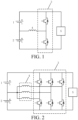
- FIG. 1 is a structural block diagram of a battery self-heating device according to an exemplary embodiment of the present disclosure.
- the device includes a bridge arm converter 3, an energy storage element 5, an inductor 4, and a controller (not shown).
- a first bus terminal of the bridge arm converter 3 is connected to a positive electrode of a first power battery 1, and a second bus terminal of the bridge arm converter 3 is connected to a negative electrode of a second power battery 2.
- a first end of the inductor 4 is connected to a midpoint of the bridge arm converter 3, and a second end of the inductor 4 is connected to a negative electrode of the first power battery 1 and a positive electrode of the second power battery 2.
- the energy storage element 5 is connected in parallel between the positive electrode of the first power battery 1 and the negative electrode of the second power battery 2, a first end of the energy storage element 5 is connected to the first bus terminal of the bridge arm converter 3, and a second end of the energy storage element 5 is connected to the second bus terminal of the bridge arm converter 3.
- the controller is configured to control, in a preset state, connection and disconnection of the bridge arm converter 3 to enablethe first power battery 1 and the second power battery 2 to be respectively charged/discharged by the inductor 4, and to respectively form a freewheeling circuit with the energy storage element 5 to realize continuous heating of the first power battery 1 and the second power battery 2.
- the first power battery 1 and the second power battery 2 may be power batteries in the same vehicle.
- the first power battery 1 and the second power battery 2 may be two power batteries arranged separately, or may be two parts of a power battery obtained by segmenting an original power battery in a vehicle. For example, a midpoint of an original power battery in a vehicle may be led out to segment the power battery in the vehicle into the first power battery 1 and the second power battery 2.
- the bridge arm converter 3 may be a bridge arm converter 3 in a motor controller in the vehicle.
- the inductor 4 may be an inductor 4 in a motor controlled by the motor controller in the vehicle.
- the controller may be a controller in any form, which may be a controller arranged separately, or may be a control module integrated in a Vehicle Control Unit (VCU) or the like.
- VCU Vehicle Control Unit
- the preset state may be a state that the first power battery 1 and the second power battery 2 need to be heated, for example, electric quantities of the first power battery 1 and the second power battery 2 are lower than a preset electric quantity threshold, or temperatures of the first power battery 1 and the second power battery 2 are lower than a preset temperature threshold.
- the controller controls connection and disconnection of the bridge arm converter 3 in the preset state, such that an oscillation current is generated by each of the first power battery 1 and the second power battery 2 by the inductor 4, and the first power battery 1 and the second power battery 2 are respectively charged/discharged by the inductor 4 to realize heating of the first power battery 1 and the second power battery 2.
- self-heating of the power battery can be realized without additional heating equipment, and the first power battery 1 and the second power battery 2 can respectively generate an oscillation current by the inductor 4 to charge and discharge, that is, when the first power battery 1 is discharged, the second power battery 2 is charged; and when the second power battery 2 is discharged, the first power battery 1 is charged. Therefore, a total voltage of the first power battery 1 and the second power battery 2 can be ensured to be relatively stable and unchanged, so that battery ripples in a battery self-heating process can be reduced, and electrical safety in the vehicle can be ensured.
- the energy storage element 5 is connected in parallel between the first power battery 1 and the second power battery 2, so that currents in the first power battery 1 and the second power battery 2 will not be interrupted in any state that the first power battery 1 is charged/discharged and the second power battery 2 is charged/discharged, and the heating of the first power battery 1 and the second power battery 2 is continuous, thereby further ensuring self-heating efficiency of the battery, and preventing a harmonic hazard due to an interrupted current in the battery.
- a battery self-heating device that provides freewheeling capacity by using an energy storage element.
- Two power batteries are provided, and an energy storage element is provided for freewheeling to generate an oscillation current between each of the two power batteries and an inductor to realize low-cost and high-efficient battery self-heating, and the stability of the total voltage of the two power batteries and the continuous flow of current in the batteries can also be ensured, thereby ensuring the safety of the batteries during a self-heating process.
- the bridge arm converter 3 may include one phase of bridge arm or multiple phases of bridge arms.
- the number of phases in the bridge arm converter 3 is not limited, and may be specifically determined according to the bridge arm converter actually applied to a motor controller of a vehicle.
- the bridge arm converter 3 may include three phases of bridge arms, and there may be three inductors 4, specifically as shown in FIG. 2 , which shows a schematic diagram of a battery self-heating device including a converter including three phases of bridge arms and three inductors 4 corresponding to the three phases of bridge arms.
- First ends of the inductors 4 are respectively connected to midpoints of the three phases of bridge arms.
- Second ends of the inductors 4 are connected to a negative electrode of the first power battery 1 and a positive electrode of the second power battery 2 after being connected together.
- the currents flowing through the inductors 4 in the motor have different directions to ensure that a total current entering a neutral point of the motor is equal to a total current flowing out of the neutral point of the motor, for example, one phase in and one phase out, or one phase in and two phases out, or one phase out and two phases inlet. Therefore, a maximum current flowing through a conventional motor can only be a limited current of one phase inductor 4.
- FIG. 1 the schematic diagram of the battery self-heating device according to the present disclosure shown in FIG.
- the inductors 4 can be led out through second ends of the inductors 4 connected to the negative electrode of the first power battery 1 and the positive electrode of the second power battery 2, so that three phases of currents in the inductors 4 may be in the same direction. Therefore, the magnitudes of the currents that can flow through the inductors 4 are significantly increased, and the maximum current flowing capacity of the motor where the inductors 4 are located can be fully played. The higher the current, the more heat generated in the first power battery 1 and the second power battery 2, so the battery self-heating efficiency achieved by this embodiment can be further improved.
- the bridge arm converter 3 includes the three phases of bridge arms and the three inductors 4 respectively connected with the midpoints of the three phases of bridge arms, if the currents in the three inductors 4 are the same, the magnitudes of the currents in the three inductors 4 are equal.
- a real-time electromagnetic force synthesized in a motor where the inductors 4 are located is zero, thereby realizing zero torque output and ensuring that the motor remains stationary in a self-heating process without any additional torque control.
- the energy storage element 5 may be a capacitor.
- the freewheeling circuit may further include other elements, for example the inductor 4 in FIG. 5 and another power battery in FIG. 7 , which will not be repeated here).
- a current flow direction when one of the first power battery 1 and the second power battery 2 is charged/discharged by the inductor 4 is as first direction (as shown in FIG. 4 , FIG. 6 , FIG. 8 , and FIG. 10 )
- a freewheeling current flow direction of the other of the first power battery 1 and the second power battery 2 is a second direction (as shown in FIG. 5 , FIG. 7 , FIG. 9 , and FIG. 11 ), and the first direction is opposite to the second direction.
- the controller is configured to control, in the preset state, alternating connection and disconnection of an upper bridge arm and a lower bridge arm of the bridge arm converter 3 to enable the first power battery 1 and the second power battery 2 to be respectively charged/discharged by the inductor 4, and to respectively form a freewheeling circuit with the energy storage element 5 to realize continuous heating of the first power battery 1 and the second power battery 2.
- a specific alternating connection and disconnection manner may be shown in FIG. 4 to FIG. 11 .
- Reference signs of various devices in FIG. 4 to FIG. 11 are not shown and may be referred to the reference signs of various devices in FIG. 1 to FIG. 3 .
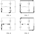
- FIG. 4 to FIG. 11 are respectively schematic diagrams of current flow directions of four stages in a current cycle period in a battery self-heating process according to an exemplary embodiment of the present disclosure.
- the upper bridge arm of the bridge arm converter 3 is controlled to be connected, the lower bridge arm is controlled to be disconnected, the first power battery 1 is discharged, the energy storage element 5 is discharged, the second power battery 2 is charged, and the inductor 4 is charged.
- a flow direction of an oscillation current for self-heating the battery is shown in FIG. 4 .
- the current flows out from the positive electrode of the first power battery 1, and flows through the upper bridge arm of the bridge arm converter 3 and the inductor 4 and flows back to the negative electrode of the first power battery 1.
- the first power battery 1 discharges to the inductor 4.
- a flow direction of a freewheeling current is shown in FIG. 5 .
- the current flows out from the positive electrode of the energy storage element 5, and flows through the upper bridge arm of the bridge arm converter 3, the inductor 4, and the second power battery 2 and flows back to the negative electrode of the energy storage element 5.
- the second power battery 2 is charged.
- a discharging process shown in FIG. 4 and a freewheeling current charging process shown in FIG. 5 are performed simultaneously. Therefore, in the first stage, there are currents flowing through the first power battery 1 and the second power battery 2 simultaneously, and simultaneous self-heating is realized. Moreover, current directions of the first power battery 1 and the second power battery 2 are opposite. Changes of terminal voltages of the first power battery 1 and the second power battery 2 may cancel each other out. An overall terminal voltage fluctuation of a battery pack is small, which can reduce ripples of the battery pack.
- the upper bridge arm of the bridge arm converter 3 is controlled to be disconnected, the lower bridge arm is controlled to be connected, the first power battery 1 is discharged, the inductor 4 is discharged, the second power battery 2 is charged, and the energy storage element 5 is charged.
- a flow direction of an oscillation current for self-heating the battery is shown in FIG. 6 .
- the current flows out from the inductor 4 to the positive electrode of the second power battery 2, flows out from the negative electrode of the second power battery 2, flows through the lower bridge arm of the bridge arm converter 3 and flows back to the inductor 4.
- the second power battery 2 is charged by the inductor 4.
- a flow direction of a freewheeling current is shown in FIG. 7 .
- the first power battery 1 is connected in series with the second power battery 2.
- the current flows out from the positive electrode of the first power battery 1, flows through the energy storage element 5 and flows back to the negative electrode of the second battery power 2.
- the first power battery 1 and the second power battery 2 discharge to the energy storage element 5 together.
- a charging process shown in FIG. 6 and a freewheeling current discharging process shown in FIG. 7 are performed simultaneously. Therefore, in the first stage, there are currents flowing through the first power battery 1 and the second power battery 2 simultaneously, and simultaneous self-heating is realized. Moreover, current directions of the first power battery 1 and the second power battery 2 are opposite. Changes of terminal voltages of the first power battery 1 and the second power battery 2 may cancel each other out. An overall terminal voltage fluctuation of a battery pack is small, which can reduce ripples of the battery pack.
- the third stage the upper bridge arm of the bridge arm converter 3 is remained disconnected, and the lower bridge arm is connected.
- the first power battery 1 is charged, the inductor 4 is charged, the second power battery 2 is discharged, and the energy storage element 5 is discharged.
- a flow direction of an oscillation current for self-heating the battery is shown in FIG. 8 .
- the current flows out from the positive electrode of the second power battery 2, flows through the inductor 4 and the lower bridge arm of the bridge arm converter 3 and flows back to the second power battery 2.
- the second power battery 2 discharges to the inductor 4.
- a flow direction of a freewheeling current is shown in FIG. 9 .
- the current flows out from the positive electrode of the energy storage element 5, flows through the first power battery 1, the inductor 4, and the lower bridge arm of the bridge arm converter 3 and flows back to the negative electrode of the energy storage element 5.
- the first power battery 1 is charged.
- a discharging process shown in FIG. 8 and a freewheeling current charging process shown in FIG. 9 are performed simultaneously. Therefore, in the first stage, there are currents flowing through the first power battery 1 and the second power battery 2 simultaneously, and simultaneous self-heating is realized. Moreover, current directions of the first power battery 1 and the second power battery 2 are opposite. Changes of terminal voltages of the first power battery 1 and the second power battery 2 may cancel each other out. An overall terminal voltage fluctuation of a battery pack is small, which can reduce ripples of the battery pack.
- the upper bridge arm of the bridge arm converter 3 is controlled to be connected, and the lower bridge arm is controlled to be disconnected.
- the first power battery 1 is charged, the energy storage element 5 is charged, the second power battery 2 is discharged, and the inductor 4 is discharged.
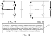
- a flow direction of an oscillation current for self-heating the battery is shown in FIG. 10 .
- the current flows out from the inductor 4, and flows through the upper bridge arm of the bridge arm converter 3, flows to the positive electrode of the first power battery 1, flows out from the negative electrode of the first power battery 1 and flows back to the inductor 4.
- the first power battery 1 is charged by the inductor 4.
- a flow direction of a freewheeling current is shown in FIG. 11 .
- the first power battery 1 is connected in series with the second power battery 2.
- the current flows out from the positive electrode of the first power battery 1, flows through the energy storage element 5 and flows back to the negative electrode of the second battery power 2.
- the first power battery 1 and the second power battery 2 discharge to the energy storage element 5
- a charging process shown in FIG. 10 and a freewheeling current discharging process shown in FIG. 11 are performed simultaneously. Therefore, in the first stage, there are currents flowing through the first power battery 1 and the second power battery 2 simultaneously, and simultaneous self-heating is realized. Moreover, current directions of the first power battery 1 and the second power battery 2 are opposite. Changes of terminal voltages of the first power battery 1 and the second power battery 2 may cancel each other out. An overall terminal voltage fluctuation of a battery pack is small, which can reduce ripples of the battery pack.
- the controller is configured to control, in the preset state, alternating connection and disconnection of the upper bridge arm and the lower bridge arm of the bridge arm converter 3 according to a preset duty cycle allocation setting.
- the controller may accurately determine a time for switching connected and disconnected states of the upper bridge arm and the lower bridge arm according to the preset duty cycle allocation setting to switch from the stage shown in FIG. 4 and FIG. 5 to the stage shown in FIG. 6 and FIG. 7 and switch from the stage shown in FIG. 8 and FIG. 9 to the stage shown in FIG. 10 and FIG. 11 to control accurately.
- the controller may be configured to control, in the preset state, the upper bridge arm of the bridge arm converter 3 to be disconnected and the lower bridge arm of the bridge arm converter 3 to be connected when the upper bridge arm of the bridge arm converter 3 is in a connected state, the lower bridge arm of the bridge arm converter 3 is in a disconnected state, and duration that the upper bridge arm of the bridge arm converter 3 is in the connected state reaches first preset duration in the preset duty cycle allocation setting.
- the stage shown in FIG. 4 and FIG. 5 is switched to the stage shown in FIG. 6 and FIG. 7 .
- the upper bridge arm of the bridge arm converter 3 is controlled to be connected and the lower bridge arm of the bridge arm converter 3 is controlled to be disconnected when the lower bridge arm of the bridge arm converter 3 is in a connected state, the upper bridge arm of the bridge arm converter 3 is in a disconnected state, and duration that the lower bridge arm of the bridge arm converter 3 reaches second preset duration in the preset duty cycle allocation setting.
- the stage shown in FIG. 8 and FIG. 9 is switched to the stage shown in FIG. 10 and FIG. 11 .
- Both the first preset duration and the second preset duration in the preset duty cycle allocation setting may be determined empirical data, or may be calibrated in advance according to experimental data, or may be determined according to a formula.
- the formula may characterize a correspondence between various thresholds and environmental information. When the environmental information changes, various thresholds may change correspondingly.
- the environmental information may include, for example, battery usage duration, State of Charge (SOC) information, a battery temperature, and an ambient temperature.
- SOC State of Charge
- the inductor 4 is switched from releasing energy to the first power battery 1 to receiving energy of the first power battery 1 and the energy storage element 5, and the energy storage element 5 is switched from receiving the energy of the first power battery 1 and the second power battery 2 to releasing energy to the second power battery 2 and the inductor 4 according to a connection time of the upper bridge arm of the bridge arm converter 3.
- the stage shown in FIG. 10 and FIG. 11 is switched to the stage shown in FIG. 4 and FIG. 5 .
- the inductor 4 is switched from releasing energy to the second power battery 2 to receiving energy of the second power battery 2 and the energy storage element 5, and the energy storage element 5 is switched from receiving the energy of the first power battery 1 and the second power battery 2 to releasing energy to the first power battery 1 and the inductor 4 according to a connection time of the lower bridge arm of the bridge arm converter 3.
- the stage shown in FIG. 6 and FIG. 7 is switched to the stage shown in FIG. 8 and FIG. 9 .
- first duration that the inductor 4 receives the energy of the first power battery 1 and the energy storage element 5 is greater than second duration that the inductor 4 releases the energy to the second power battery 2 when the preset duty cycle allocation setting is determined.
- the duration in the stage shown in FIG. 4 and FIG. 5 is greater than the duration in the stage shown in FIG. 6 and FIG. 7 .
- Third duration that the inductor 4 receives the energy of the second power battery 2 and the energy storage element 5 is ensured to be greater than fourth duration that the inductor 4 releases the energy to the first power battery 1.
- the duration in the stage shown in FIG. 8 and FIG. 9 is greater than the duration in the stage shown in FIG. 10 and FIG. 11 .
- the controller is further configured to obtain, in the preset state, a current value of the inductor 4 and/or a voltage value at both ends of the inductor 4, and control alternating connection and disconnection of the upper bridge arm and the lower bridge arm of the bridge arm converter 3 according to the current value and/or the voltage value. Thresholds of the current value and/or the voltage current may alternatively be determined according to empirical data, or may be calibrated in advance according to experimental data.
- FIG. 12 is a flowchart of a battery self-heating method according to an exemplary embodiment of the present disclosure. As shown in FIG. 12 , the method may include step 101.
- connection and disconnection of a bridge arm converter 3 are controlled to enable a first power battery 1 and a second power battery 2 to be respectively charged/discharged by an inductor 4, and to respectively form a freewheeling circuit by an energy storage element 5 to realize continuous heating of the first power battery 1 and the second power battery 2.
- a first bus terminal of the bridge arm converter 3 is connected to a positive electrode of the first power battery 1, and a second bus terminal of the bridge arm converter 3 is connected to a negative electrode of the second power battery 2.
- a first end of the inductor 4 is connected to a midpoint of the bridge arm converter 3, and a second end of the inductor 4 is connected to a negative electrode of the first power battery 1 and a positive electrode of the second power battery 2.
- the energy storage element 5 is connected in parallel between the positive electrode of the first power battery 1 and the negative electrode of the second power battery 2, a first end of the energy storage element 5 is connected to the first bus terminal of the bridge arm converter 3, and a second end of the energy storage element 5 is connected to the second bus terminal of the bridge arm converter 3.
- a battery self-heating device that provides freewheeling capacity by using an energy storage element.
- Two power batteries are provided, and an energy storage element is provided for freewheeling to generate an oscillation current between each of the two power batteries and an inductor to realize low-cost and high-efficient battery self-heating, and the stability of the total voltage of the two power batteries and the continuous flow of current in the batteries can also be ensured, thereby ensuring the safety of the batteries during a self-heating process.
- the other of the first power battery and the second power battery form a freewheeling circuit with the energy storage element.
- a current flow direction when one of the first power battery and the second power battery is charged/discharged by the inductor is a first direction
- a freewheeling current flow direction of the other of the first power battery and the second power battery is a second direction
- the first direction is opposite to the second direction
- the method further includes: in the preset state, alternating connection and disconnection of an upper bridge arm and a lower bridge arm of the bridge arm converter 3 are controlled to enable the first power battery 1 and the second power battery 2 to be respectively charged/discharged by the inductor 4, and to respectively form a freewheeling circuit with the energy storage element 5 to realize continuous heating of the first power battery 1 and the second power battery 2.
- the method further includes: in the preset state, alternating connection and disconnection of the upper bridge arm and the lower bridge arm of the bridge arm converter 3 are controlled according to a preset duty cycle allocation setting.
- the method further includes: in the preset state, the upper bridge arm of the bridge arm converter 3 is controlled to be disconnected and the lower bridge arm of the bridge arm converter 3 is controlled to be connected when the upper bridge arm of the bridge arm converter 3 is in a connected state, the lower bridge arm of the bridge arm converter 3 is in a disconnected state, and duration that the upper bridge arm of the bridge arm converter 3 reaches first preset duration in the preset duty cycle allocation setting.
- the upper bridge arm of the bridge arm converter 3 is controlled to be connected and the lower bridge arm of the bridge arm converter 3 is controlled to be disconnected when the lower bridge arm of the bridge arm converter 3 is in a connected state, the upper bridge arm of the bridge arm converter 3 is in a disconnected state, and duration that the lower bridge arm of the bridge arm converter 3 reaches second preset duration in the preset duty cycle allocation setting.
- the inductor 4 when the upper bridge arm of the bridge arm converter 3 is in the connected state, the inductor 4 is switched from releasing energy to the first power battery 1 to receiving energy of the first power battery 1 and the energy storage element 5, and the energy storage element 5 is switched from receiving the energy of the first power battery 1 and the second power battery 2 to releasing energy to the second power battery 2 and the inductor 4 according to a connection time of the upper bridge arm of the bridge arm converter 3.
- the inductor 4 When the lower bridge arm of the bridge arm converter 3 is in the connected state, the inductor 4 is switched from releasing energy to the second power battery 2 to receiving energy of the second power battery 2 and the energy storage element 5, and the energy storage element 5 is switched from receiving the energy of the first power battery 1 and the second power battery 2 to releasing energy to the first power battery 1 and the inductor 4 according to a connection time of the lower bridge arm of the bridge arm converter 3.
- first duration that the inductor 4 receives the energy of the first power battery 1 and the energy storage element 5 is greater than second duration that the inductor 4 releases the energy to the second power battery 2.
- Third duration that the inductor 4 receives the energy of the second power battery 2 and the energy storage element 5 is greater than fourth duration that the inductor 4 releases the energy to the first power battery 1.
- the method further includes: in the preset state, a current value of the inductor 4 and/or a voltage value at both ends of the inductor 4 are obtained, and alternating connection and disconnection of the upper bridge arm and the lower bridge arm of the bridge arm converter 3 are controlled according to the current value and/or the voltage value.
- the inductor 4 is an inductor 4 in a driving motor of a vehicle.
- the energy storage element 5 includes a capacitor.
- the bridge arm converter 3 is a three-phase converter, and includes three phases of bridge arms.
- the present disclosure further provides a vehicle.
- the vehicle includes the battery self-heating device described above.
Landscapes
- Engineering & Computer Science (AREA)
- Power Engineering (AREA)
- Manufacturing & Machinery (AREA)
- General Chemical & Material Sciences (AREA)
- Electrochemistry (AREA)
- Chemical Kinetics & Catalysis (AREA)
- Chemical & Material Sciences (AREA)
- Mechanical Engineering (AREA)
- Transportation (AREA)
- Life Sciences & Earth Sciences (AREA)
- Sustainable Development (AREA)
- Sustainable Energy (AREA)
- Automation & Control Theory (AREA)
- Physics & Mathematics (AREA)
- Electromagnetism (AREA)
- Secondary Cells (AREA)
- Charge And Discharge Circuits For Batteries Or The Like (AREA)
Abstract
Description
- The present disclosure claims priority to and benefits of
Chinese Patent Application No. "202210474898.0", entitled "BATTERY SELF-HEATING DEVICE AND METHOD, AND VEHICLE" and filed on April 29, 2022 - The present disclosure relates to the technical field of batteries, and more specifically, to a battery self-heating device and method, and a vehicle.
- In a low-temperature environment, the temperature of a lithium-ion power battery of a pure electric vehicle is too low. Due to the decrease of the activity of a positive electrode material, a negative electrode material, and an electrolyte of the battery, and the internal resistance of the battery will increase as the temperature decreases, in the low-temperature environment, the charge-discharge performance of the pure electric vehicle will significantly decrease. Therefore, the power battery of the pure electric vehicle has to be heated to increase the temperature of the body of the power battery and ensure normal use of the pure electric vehicle under cold conditions.
- Existing methods for heating a power battery of an electric vehicle mainly include external heating and internal heating. The external heating is to heat the battery by adding additional heating equipment, and meanwhile, a water way, an air way, a pipeline, a low-pressure system, and the like need to be allocated, resulting in an increase of total cost. Due to long water way and pipeline, heat loss is significant, and heating time is slow and long. An internal heating principle is mainly that a battery is charge and discharge cyclically, and heat is generated relying on the internal resistance of the battery. However, in battery self-heating technologies that can be realized at present, heating power is limited, and charging and discharging of a battery pack are performed alternately, which will cause voltage fluctuations (ripples) at both ends of the battery pack.
- An objective of the present disclosure is to provide a battery self-heating device and method, and a vehicle. Two power batteries are provided, and an energy storage element is provided for freewheeling to generate an oscillation current between each of the two power batteries and an inductor to realize low-cost and high-efficient battery self-heating, and the stability of the total voltage of the two power batteries and the continuous flow of current in the batteries can also be ensured, thereby ensuring the safety of the batteries during a self-heating process.
- To achieve the foregoing objective, the present disclosure provides a battery self-heating device. The device includes a bridge arm converter, an energy storage element, an inductor, and a controller. A first bus terminal of the bridge arm converter is connected to a positive electrode of a first power battery, and a second bus terminal of the bridge arm converter is connected to a negative electrode of a second power battery. A first end of the inductor is connected to a midpoint of the bridge arm converter, and a second end of the inductor is connected to a negative electrode of the first power battery and a positive electrode of the second power battery. The energy storage element is connected in parallel between the positive electrode of the first power battery and the negative electrode of the second power battery, a first end of the energy storage element is connected to the first bus terminal of the bridge arm converter, and a second end of the energy storage element is connected to the second bus terminal of the bridge arm converter. The controller is configured to control, in a preset state, connection and disconnection of the bridge arm converter to enable the first power battery and the second power battery to be respectively charged/discharged by the inductor, and to respectively form a freewheeling circuit with the energy storage element to realize continuous heating of the first power battery and the second power battery.
- Optionally, when one of the first power battery and the second power battery is charged/discharged by the inductor, the other of the first power battery and the second power battery form a freewheeling circuit with the energy storage element.
- Optionally, a current flow direction when one of the first power battery and the second power battery is charged/discharged by the inductor is a first direction, a freewheeling current flow direction of the other of the first power battery and the second power battery is a second direction, and the first direction is opposite to the second direction.
- Optionally, the controller is configured to control, in the preset state, alternating connection and disconnection of an upper bridge arm and a lower bridge arm of the bridge arm converter to enable the first power battery and the second power battery to be respectively charged/discharged by the inductor, and to respectively form a freewheeling circuit with the energy storage element to realize continuous heating of the first power battery and the second power battery.
- Optionally, the controller is configured to control, in the preset state, alternating connection and disconnection of the upper bridge arm and the lower bridge arm of the bridge arm converter according to a preset duty cycle allocation setting.
- Optionally, the controller is configured to:in the preset state, control the upper bridge arm of the bridge arm converter to be disconnected and the lower bridge arm of the bridge arm converter to be connected when the upper bridge arm of the bridge arm converter is in a connected state, the lower bridge arm of the bridge arm converter is in a disconnected state, and duration that the upper bridge arm of the bridge arm converter reaches first preset duration in the preset duty cycle allocation setting; and control the upper bridge arm of the bridge arm converter to be connected and the lower bridge arm of the bridge arm converter to be disconnected when the lower bridge arm of the bridge arm converter is in a connected state, the upper bridge arm of the bridge arm converter is in a disconnected state, and duration that the lower bridge arm of the bridge arm converter reaches second preset duration in the preset duty cycle allocation setting.
- Optionally, when the upper bridge arm of the bridge arm converter is in the connected state, the inductor is switched from releasing energy to the first power battery to receiving energy of the first power battery and the energy storage element, and the energy storage element is switched from receiving the energy of the first power battery and the second power battery to releasing energy to the second power battery and the inductor according to a connection time of the upper bridge arm of the bridge arm converter; and when the lower bridge arm of the bridge arm converter is in the connected state, the inductor is switched from releasing energy to the second power battery to receiving energy of the second power battery and the energy storage element, and the energy storage element is switched from receiving the energy of the first power battery and the second power battery to releasing energy to the first power battery and the inductor according to a connection time of the lower bridge arm of the bridge arm converter.
- Optionally, first duration that the inductor receives the energy of the first power battery and the energy storage element is greater than second duration that the inductor releases the energy to the second power battery; and third duration that the inductor receives the energy of the second power battery and the energy storage element is greater than fourth duration that the inductor releases the energy to the first power battery.
- Optionally, the controller is configured to: in the preset state, obtain a current value of the inductor and/or a voltage value at both ends of the inductor, and control alternating connection and disconnection of the upper bridge arm and the lower bridge arm of the bridge arm converter according to the current value and/or the voltage value.
- Optionally, the inductor is an inductor in a driving motor of a vehicle.
- Optionally, the energy storage element includes a capacitor.
- Optionally, the bridge arm converter is a three-phase converter, and includes three phases of bridge arms.
- The present disclosure further provides a battery self-heating method. The method includes: controlling, in a preset state, connection and disconnection of a bridge arm converter to enable a first power battery and a second power battery to be respectively charged/discharged by an inductor, and to respectively form a freewheeling circuit by an energy storage element to realize continuous heating of the first power battery and the second power battery. A first bus terminal of the bridge arm converter is connected to a positive electrode of the first power battery, and a second bus terminal of the bridge arm converter is connected to a negative electrode of the second power battery. A first end of the inductor is connected to a midpoint of the bridge arm converter, and a second end of the inductor is connected to a negative electrode of the first power battery and a positive electrode of the second power battery. The energy storage element is connected in parallel between the positive electrode of the first power battery and the negative electrode of the second power battery, a first end of the energy storage element is connected to the first bus terminal of the bridge arm converter, and a second end of the energy storage element is connected to the second bus terminal of the bridge arm converter.
- The present disclosure further provides a vehicle. The vehicle includes the battery self-heating device described above.
- Through the foregoing technical solution, a battery self-heating device that provides freewheeling capacity by using an energy storage element is provided. Two power batteries are provided, and an energy storage element is provided for freewheeling to generate an oscillation current between each of the two power batteries and an inductor to realize low-cost and high-efficient battery self-heating, and the stability of the total voltage of the two power batteries and the continuous flow of current in the batteries can also be ensured, thereby ensuring the safety of the batteries during a self-heating process.
- Other features and advantages of the present disclosure will be described below the following detailed description.
- Accompanying drawings are used to provide further understanding of the present disclosure, constitute a part of this specification, and are used to explain the present disclosure together with specific embodiments below, and do not constitute a limitation to the present disclosure. In the accompanying drawings:
-
FIG. 1 is a structural block diagram of a battery self-heating device according to an exemplary embodiment of the present disclosure. -
FIG. 2 is a structural block diagram of a battery self-heating device according to another exemplary embodiment of the present disclosure. -
FIG. 3 is a structural block diagram of a battery self-heating device according to another exemplary embodiment of the present disclosure. -
FIG. 4 is a schematic diagram of a flow direction of an oscillation current in a first stage in a current cycle period in a battery self-heating process according to an exemplary embodiment of the present disclosure. -
FIG. 5 is a schematic diagram of a flow direction of a freewheeling current in a first stage in a current cycle period in a battery self-heating process according to an exemplary embodiment of the present disclosure. -
FIG. 6 is a schematic diagram of a flow direction of an oscillation current in a second stage in a current cycle period in a battery self-heating process according to an exemplary embodiment of the present disclosure. -
FIG. 7 is a schematic diagram of a flow direction of a freewheeling current in a second stage in a current cycle period in a battery self-heating process according to an exemplary embodiment of the present disclosure. -
FIG. 8 is a schematic diagram of a flow direction of an oscillation current in a third stage in a current cycle period in a battery self-heating process according to an exemplary embodiment of the present disclosure. -
FIG. 9 is a schematic diagram of a flow direction of a freewheeling current in a third stage in a current cycle period in a battery self-heating process according to an exemplary embodiment of the present disclosure. -
FIG. 10 is a schematic diagram of a flow direction of an oscillation current in a fourth stage in a current cycle period in a battery self-heating process according to an exemplary embodiment of the present disclosure. -
FIG. 11 is a schematic diagram of a flow direction of a freewheeling current in a fourth stage in a current cycle period in a battery self-heating process according to an exemplary embodiment of the present disclosure. -
FIG. 12 is a flowchart of a battery self-heating method according to an exemplary embodiment of the present disclosure. - In the drawings:
1 first power battery 2 second power battery 3 bridge arm converter 4 inductor 5 energy storage element - Specific embodiments of the present disclosure are described in detail below with reference to accompanying drawings. It is to be understood that the specific embodiments described herein are merely used to describe and explain the present disclosure, but are not used to limit the present disclosure.
- It is to be noted that, all actions for obtaining signals, information or data in the present disclosure are performed on the premise of complying with corresponding data protection regulations and policies of the country where the signals, the information or the data are located, and are performed in a case that authorization is granted by a corresponding device owner.
-
FIG. 1 is a structural block diagram of a battery self-heating device according to an exemplary embodiment of the present disclosure. As shown inFIG. 1 , the device includes abridge arm converter 3, anenergy storage element 5, aninductor 4, and a controller (not shown). A first bus terminal of thebridge arm converter 3 is connected to a positive electrode of afirst power battery 1, and a second bus terminal of thebridge arm converter 3 is connected to a negative electrode of asecond power battery 2. A first end of theinductor 4 is connected to a midpoint of thebridge arm converter 3, and a second end of theinductor 4 is connected to a negative electrode of thefirst power battery 1 and a positive electrode of thesecond power battery 2. Theenergy storage element 5 is connected in parallel between the positive electrode of thefirst power battery 1 and the negative electrode of thesecond power battery 2, a first end of theenergy storage element 5 is connected to the first bus terminal of thebridge arm converter 3, and a second end of theenergy storage element 5 is connected to the second bus terminal of thebridge arm converter 3. The controller is configured to control, in a preset state, connection and disconnection of thebridge arm converter 3 to enablethefirst power battery 1 and thesecond power battery 2 to be respectively charged/discharged by theinductor 4, and to respectively form a freewheeling circuit with theenergy storage element 5 to realize continuous heating of thefirst power battery 1 and thesecond power battery 2. - The
first power battery 1 and thesecond power battery 2 may be power batteries in the same vehicle. Thefirst power battery 1 and thesecond power battery 2 may be two power batteries arranged separately, or may be two parts of a power battery obtained by segmenting an original power battery in a vehicle. For example, a midpoint of an original power battery in a vehicle may be led out to segment the power battery in the vehicle into thefirst power battery 1 and thesecond power battery 2. Thebridge arm converter 3 may be abridge arm converter 3 in a motor controller in the vehicle. Theinductor 4 may be aninductor 4 in a motor controlled by the motor controller in the vehicle. The controller may be a controller in any form, which may be a controller arranged separately, or may be a control module integrated in a Vehicle Control Unit (VCU) or the like. - The preset state may be a state that the
first power battery 1 and thesecond power battery 2 need to be heated, for example, electric quantities of thefirst power battery 1 and thesecond power battery 2 are lower than a preset electric quantity threshold, or temperatures of thefirst power battery 1 and thesecond power battery 2 are lower than a preset temperature threshold. - The controller controls connection and disconnection of the
bridge arm converter 3 in the preset state, such that an oscillation current is generated by each of thefirst power battery 1 and thesecond power battery 2 by theinductor 4, and thefirst power battery 1 and thesecond power battery 2 are respectively charged/discharged by theinductor 4 to realize heating of thefirst power battery 1 and thesecond power battery 2. Thus, self-heating of the power battery can be realized without additional heating equipment, and thefirst power battery 1 and thesecond power battery 2 can respectively generate an oscillation current by theinductor 4 to charge and discharge, that is, when thefirst power battery 1 is discharged, thesecond power battery 2 is charged; and when thesecond power battery 2 is discharged, thefirst power battery 1 is charged. Therefore, a total voltage of thefirst power battery 1 and thesecond power battery 2 can be ensured to be relatively stable and unchanged, so that battery ripples in a battery self-heating process can be reduced, and electrical safety in the vehicle can be ensured. - In addition, the
energy storage element 5 is connected in parallel between thefirst power battery 1 and thesecond power battery 2, so that currents in thefirst power battery 1 and thesecond power battery 2 will not be interrupted in any state that thefirst power battery 1 is charged/discharged and thesecond power battery 2 is charged/discharged, and the heating of thefirst power battery 1 and thesecond power battery 2 is continuous, thereby further ensuring self-heating efficiency of the battery, and preventing a harmonic hazard due to an interrupted current in the battery. - Through the foregoing technical solution, a battery self-heating device that provides freewheeling capacity by using an energy storage element is provided. Two power batteries are provided, and an energy storage element is provided for freewheeling to generate an oscillation current between each of the two power batteries and an inductor to realize low-cost and high-efficient battery self-heating, and the stability of the total voltage of the two power batteries and the continuous flow of current in the batteries can also be ensured, thereby ensuring the safety of the batteries during a self-heating process.
- In a possible embodiment, the
bridge arm converter 3 may include one phase of bridge arm or multiple phases of bridge arms. In the present disclosure, the number of phases in thebridge arm converter 3 is not limited, and may be specifically determined according to the bridge arm converter actually applied to a motor controller of a vehicle. There may be one ormore inductors 4, which may be specifically determined according to the number of phases of thebridge arm converter 3. For example, thebridge arm converter 3 may include three phases of bridge arms, and there may be threeinductors 4, specifically as shown inFIG. 2 , which shows a schematic diagram of a battery self-heating device including a converter including three phases of bridge arms and threeinductors 4 corresponding to the three phases of bridge arms. First ends of theinductors 4 are respectively connected to midpoints of the three phases of bridge arms. Second ends of theinductors 4 are connected to a negative electrode of thefirst power battery 1 and a positive electrode of thesecond power battery 2 after being connected together. - In a common circuit including a motor, at any time, the currents flowing through the
inductors 4 in the motor have different directions to ensure that a total current entering a neutral point of the motor is equal to a total current flowing out of the neutral point of the motor, for example, one phase in and one phase out, or one phase in and two phases out, or one phase out and two phases inlet. Therefore, a maximum current flowing through a conventional motor can only be a limited current of onephase inductor 4. However, in the schematic diagram of the battery self-heating device according to the present disclosure shown inFIG. 2 , in a case that thebridge arm converter 3 includes three phases of bridge arms and threeinductors 4 respectively connected to three midpoints of the three phases of bridge arms, theinductors 4 can be led out through second ends of theinductors 4 connected to the negative electrode of thefirst power battery 1 and the positive electrode of thesecond power battery 2, so that three phases of currents in theinductors 4 may be in the same direction. Therefore, the magnitudes of the currents that can flow through theinductors 4 are significantly increased, and the maximum current flowing capacity of the motor where theinductors 4 are located can be fully played. The higher the current, the more heat generated in thefirst power battery 1 and thesecond power battery 2, so the battery self-heating efficiency achieved by this embodiment can be further improved. - Moreover, in the battery self-heating device, as shown in
FIG. 2 , where thebridge arm converter 3 includes the three phases of bridge arms and the threeinductors 4 respectively connected with the midpoints of the three phases of bridge arms, if the currents in the threeinductors 4 are the same, the magnitudes of the currents in the threeinductors 4 are equal. A real-time electromagnetic force synthesized in a motor where theinductors 4 are located is zero, thereby realizing zero torque output and ensuring that the motor remains stationary in a self-heating process without any additional torque control. - In a possible embodiment, as shown in
FIG. 3 , theenergy storage element 5 may be a capacitor. - In a possible embodiment, when one of the
first power battery 1 and thesecond power battery 2 is charged/discharged by the inductor 4 (as shown inFIG. 4 ,FIG. 6 ,FIG. 8 , andFIG. 10 ), the other of thefirst power battery 1 and thesecond power battery 2 form a freewheeling circuit with the energy storage element 5 (as shown inFIG. 5 ,FIG. 7 ,FIG. 9 , andFIG. 11 , those skilled in the art are to be understood that the freewheeling circuit may further include other elements, for example theinductor 4 inFIG. 5 and another power battery inFIG. 7 , which will not be repeated here). - Moreover, a current flow direction when one of the
first power battery 1 and thesecond power battery 2 is charged/discharged by theinductor 4 is as first direction (as shown inFIG. 4 ,FIG. 6 ,FIG. 8 , andFIG. 10 ), a freewheeling current flow direction of the other of thefirst power battery 1 and thesecond power battery 2 is a second direction (as shown inFIG. 5 ,FIG. 7 ,FIG. 9 , andFIG. 11 ), and the first direction is opposite to the second direction. - In a possible embodiment, the controller is configured to control, in the preset state, alternating connection and disconnection of an upper bridge arm and a lower bridge arm of the
bridge arm converter 3 to enable thefirst power battery 1 and thesecond power battery 2 to be respectively charged/discharged by theinductor 4, and to respectively form a freewheeling circuit with theenergy storage element 5 to realize continuous heating of thefirst power battery 1 and thesecond power battery 2. A specific alternating connection and disconnection manner may be shown inFIG. 4 to FIG. 11 . Reference signs of various devices inFIG. 4 to FIG. 11 are not shown and may be referred to the reference signs of various devices inFIG. 1 to FIG. 3 . -
FIG. 4 to FIG. 11 are respectively schematic diagrams of current flow directions of four stages in a current cycle period in a battery self-heating process according to an exemplary embodiment of the present disclosure. - First stage: the upper bridge arm of the
bridge arm converter 3 is controlled to be connected, the lower bridge arm is controlled to be disconnected, thefirst power battery 1 is discharged, theenergy storage element 5 is discharged, thesecond power battery 2 is charged, and theinductor 4 is charged. A flow direction of an oscillation current for self-heating the battery is shown inFIG. 4 . The current flows out from the positive electrode of thefirst power battery 1, and flows through the upper bridge arm of thebridge arm converter 3 and theinductor 4 and flows back to the negative electrode of thefirst power battery 1. Thefirst power battery 1 discharges to theinductor 4. A flow direction of a freewheeling current is shown inFIG. 5 . The current flows out from the positive electrode of theenergy storage element 5, and flows through the upper bridge arm of thebridge arm converter 3, theinductor 4, and thesecond power battery 2 and flows back to the negative electrode of theenergy storage element 5. Thesecond power battery 2 is charged. - It is to be noted that, a discharging process shown in
FIG. 4 and a freewheeling current charging process shown inFIG. 5 are performed simultaneously. Therefore, in the first stage, there are currents flowing through thefirst power battery 1 and thesecond power battery 2 simultaneously, and simultaneous self-heating is realized. Moreover, current directions of thefirst power battery 1 and thesecond power battery 2 are opposite. Changes of terminal voltages of thefirst power battery 1 and thesecond power battery 2 may cancel each other out. An overall terminal voltage fluctuation of a battery pack is small, which can reduce ripples of the battery pack. - Second stage: the upper bridge arm of the
bridge arm converter 3 is controlled to be disconnected, the lower bridge arm is controlled to be connected, thefirst power battery 1 is discharged, theinductor 4 is discharged, thesecond power battery 2 is charged, and theenergy storage element 5 is charged. A flow direction of an oscillation current for self-heating the battery is shown inFIG. 6 . The current flows out from theinductor 4 to the positive electrode of thesecond power battery 2, flows out from the negative electrode of thesecond power battery 2, flows through the lower bridge arm of thebridge arm converter 3 and flows back to theinductor 4. Thesecond power battery 2 is charged by theinductor 4. A flow direction of a freewheeling current is shown inFIG. 7 . Thefirst power battery 1 is connected in series with thesecond power battery 2. The current flows out from the positive electrode of thefirst power battery 1, flows through theenergy storage element 5 and flows back to the negative electrode of thesecond battery power 2. Thefirst power battery 1 and thesecond power battery 2 discharge to theenergy storage element 5 together. - It is to be noted that, a charging process shown in
FIG. 6 and a freewheeling current discharging process shown inFIG. 7 are performed simultaneously. Therefore, in the first stage, there are currents flowing through thefirst power battery 1 and thesecond power battery 2 simultaneously, and simultaneous self-heating is realized. Moreover, current directions of thefirst power battery 1 and thesecond power battery 2 are opposite. Changes of terminal voltages of thefirst power battery 1 and thesecond power battery 2 may cancel each other out. An overall terminal voltage fluctuation of a battery pack is small, which can reduce ripples of the battery pack. - Third stage: the upper bridge arm of the
bridge arm converter 3 is remained disconnected, and the lower bridge arm is connected. Thefirst power battery 1 is charged, theinductor 4 is charged, thesecond power battery 2 is discharged, and theenergy storage element 5 is discharged. A flow direction of an oscillation current for self-heating the battery is shown inFIG. 8 . The current flows out from the positive electrode of thesecond power battery 2, flows through theinductor 4 and the lower bridge arm of thebridge arm converter 3 and flows back to thesecond power battery 2. Thesecond power battery 2 discharges to theinductor 4. A flow direction of a freewheeling current is shown inFIG. 9 . The current flows out from the positive electrode of theenergy storage element 5, flows through thefirst power battery 1, theinductor 4, and the lower bridge arm of thebridge arm converter 3 and flows back to the negative electrode of theenergy storage element 5. Thefirst power battery 1 is charged. - It is to be noted that, a discharging process shown in
FIG. 8 and a freewheeling current charging process shown inFIG. 9 are performed simultaneously. Therefore, in the first stage, there are currents flowing through thefirst power battery 1 and thesecond power battery 2 simultaneously, and simultaneous self-heating is realized. Moreover, current directions of thefirst power battery 1 and thesecond power battery 2 are opposite. Changes of terminal voltages of thefirst power battery 1 and thesecond power battery 2 may cancel each other out. An overall terminal voltage fluctuation of a battery pack is small, which can reduce ripples of the battery pack. - Fourth stage: the upper bridge arm of the
bridge arm converter 3 is controlled to be connected, and the lower bridge arm is controlled to be disconnected. Thefirst power battery 1 is charged, theenergy storage element 5 is charged, thesecond power battery 2 is discharged, and theinductor 4 is discharged. A flow direction of an oscillation current for self-heating the battery is shown inFIG. 10 . The current flows out from theinductor 4, and flows through the upper bridge arm of thebridge arm converter 3, flows to the positive electrode of thefirst power battery 1, flows out from the negative electrode of thefirst power battery 1 and flows back to theinductor 4. Thefirst power battery 1 is charged by theinductor 4. A flow direction of a freewheeling current is shown inFIG. 11 . Thefirst power battery 1 is connected in series with thesecond power battery 2. The current flows out from the positive electrode of thefirst power battery 1, flows through theenergy storage element 5 and flows back to the negative electrode of thesecond battery power 2. Thefirst power battery 1 and thesecond power battery 2 discharge to theenergy storage element 5 together. - It is to be noted that, a charging process shown in
FIG. 10 and a freewheeling current discharging process shown inFIG. 11 are performed simultaneously. Therefore, in the first stage, there are currents flowing through thefirst power battery 1 and thesecond power battery 2 simultaneously, and simultaneous self-heating is realized. Moreover, current directions of thefirst power battery 1 and thesecond power battery 2 are opposite. Changes of terminal voltages of thefirst power battery 1 and thesecond power battery 2 may cancel each other out. An overall terminal voltage fluctuation of a battery pack is small, which can reduce ripples of the battery pack. - In a possible embodiment, the controller is configured to control, in the preset state, alternating connection and disconnection of the upper bridge arm and the lower bridge arm of the
bridge arm converter 3 according to a preset duty cycle allocation setting. Thus, the controller may accurately determine a time for switching connected and disconnected states of the upper bridge arm and the lower bridge arm according to the preset duty cycle allocation setting to switch from the stage shown inFIG. 4 and FIG. 5 to the stage shown inFIG. 6 and FIG. 7 and switch from the stage shown inFIG. 8 and FIG. 9 to the stage shown inFIG. 10 and FIG. 11 to control accurately. - Specifically, as an example in which the upper bridge arm and the lower bridge arm of the
bridge arm converter 3 are controlled to be connected and disconnected alternately according to the preset duty cycle allocation setting, the controller may be configured to control, in the preset state, the upper bridge arm of thebridge arm converter 3 to be disconnected and the lower bridge arm of thebridge arm converter 3 to be connected when the upper bridge arm of thebridge arm converter 3 is in a connected state, the lower bridge arm of thebridge arm converter 3 is in a disconnected state, and duration that the upper bridge arm of thebridge arm converter 3 is in the connected state reaches first preset duration in the preset duty cycle allocation setting. For example, the stage shown inFIG. 4 and FIG. 5 is switched to the stage shown inFIG. 6 and FIG. 7 . The upper bridge arm of thebridge arm converter 3 is controlled to be connected and the lower bridge arm of thebridge arm converter 3 is controlled to be disconnected when the lower bridge arm of thebridge arm converter 3 is in a connected state, the upper bridge arm of thebridge arm converter 3 is in a disconnected state, and duration that the lower bridge arm of thebridge arm converter 3 reaches second preset duration in the preset duty cycle allocation setting. For example, the stage shown inFIG. 8 and FIG. 9 is switched to the stage shown inFIG. 10 and FIG. 11 . - Both the first preset duration and the second preset duration in the preset duty cycle allocation setting may be determined empirical data, or may be calibrated in advance according to experimental data, or may be determined according to a formula. The formula may characterize a correspondence between various thresholds and environmental information. When the environmental information changes, various thresholds may change correspondingly. The environmental information may include, for example, battery usage duration, State of Charge (SOC) information, a battery temperature, and an ambient temperature.
- In addition, when the upper bridge arm of the
bridge arm converter 3 is in the connected state, theinductor 4 is switched from releasing energy to thefirst power battery 1 to receiving energy of thefirst power battery 1 and theenergy storage element 5, and theenergy storage element 5 is switched from receiving the energy of thefirst power battery 1 and thesecond power battery 2 to releasing energy to thesecond power battery 2 and theinductor 4 according to a connection time of the upper bridge arm of thebridge arm converter 3. For example, the stage shown inFIG. 10 and FIG. 11 is switched to the stage shown inFIG. 4 and FIG. 5 . - When the lower bridge arm of the
bridge arm converter 3 is in the connected state, theinductor 4 is switched from releasing energy to thesecond power battery 2 to receiving energy of thesecond power battery 2 and theenergy storage element 5, and theenergy storage element 5 is switched from receiving the energy of thefirst power battery 1 and thesecond power battery 2 to releasing energy to thefirst power battery 1 and theinductor 4 according to a connection time of the lower bridge arm of thebridge arm converter 3. For example, the stage shown inFIG. 6 and FIG. 7 is switched to the stage shown inFIG. 8 and FIG. 9 . - Further, to ensure continuous flow of a freewheeling current, first duration that the
inductor 4 receives the energy of thefirst power battery 1 and theenergy storage element 5 is greater than second duration that theinductor 4 releases the energy to thesecond power battery 2 when the preset duty cycle allocation setting is determined. For example, the duration in the stage shown inFIG. 4 and FIG. 5 is greater than the duration in the stage shown inFIG. 6 and FIG. 7 . Third duration that theinductor 4 receives the energy of thesecond power battery 2 and theenergy storage element 5 is ensured to be greater than fourth duration that theinductor 4 releases the energy to thefirst power battery 1. For example, the duration in the stage shown inFIG. 8 and FIG. 9 is greater than the duration in the stage shown inFIG. 10 and FIG. 11 . - In a possible embodiment, the controller is further configured to obtain, in the preset state, a current value of the
inductor 4 and/or a voltage value at both ends of theinductor 4, and control alternating connection and disconnection of the upper bridge arm and the lower bridge arm of thebridge arm converter 3 according to the current value and/or the voltage value. Thresholds of the current value and/or the voltage current may alternatively be determined according to empirical data, or may be calibrated in advance according to experimental data. -
FIG. 12 is a flowchart of a battery self-heating method according to an exemplary embodiment of the present disclosure. As shown inFIG. 12 , the method may includestep 101. - In 101, in a preset state, connection and disconnection of a
bridge arm converter 3 are controlled to enable afirst power battery 1 and asecond power battery 2 to be respectively charged/discharged by aninductor 4, and to respectively form a freewheeling circuit by anenergy storage element 5 to realize continuous heating of thefirst power battery 1 and thesecond power battery 2. - A first bus terminal of the
bridge arm converter 3 is connected to a positive electrode of thefirst power battery 1, and a second bus terminal of thebridge arm converter 3 is connected to a negative electrode of thesecond power battery 2. A first end of theinductor 4 is connected to a midpoint of thebridge arm converter 3, and a second end of theinductor 4 is connected to a negative electrode of thefirst power battery 1 and a positive electrode of thesecond power battery 2. Theenergy storage element 5 is connected in parallel between the positive electrode of thefirst power battery 1 and the negative electrode of thesecond power battery 2, a first end of theenergy storage element 5 is connected to the first bus terminal of thebridge arm converter 3, and a second end of theenergy storage element 5 is connected to the second bus terminal of thebridge arm converter 3. - Through the foregoing technical solution, a battery self-heating device that provides freewheeling capacity by using an energy storage element is provided. Two power batteries are provided, and an energy storage element is provided for freewheeling to generate an oscillation current between each of the two power batteries and an inductor to realize low-cost and high-efficient battery self-heating, and the stability of the total voltage of the two power batteries and the continuous flow of current in the batteries can also be ensured, thereby ensuring the safety of the batteries during a self-heating process.
- In a possible embodiment, when one of the first power battery and the second power battery is charged/discharged by the inductor, the other of the first power battery and the second power battery form a freewheeling circuit with the energy storage element.
- In a possible embodiment, a current flow direction when one of the first power battery and the second power battery is charged/discharged by the inductor is a first direction, a freewheeling current flow direction of the other of the first power battery and the second power battery is a second direction, and the first direction is opposite to the second direction.
- In a possible embodiment, the method further includes: in the preset state, alternating connection and disconnection of an upper bridge arm and a lower bridge arm of the
bridge arm converter 3 are controlled to enable thefirst power battery 1 and thesecond power battery 2 to be respectively charged/discharged by theinductor 4, and to respectively form a freewheeling circuit with theenergy storage element 5 to realize continuous heating of thefirst power battery 1 and thesecond power battery 2. - In a possible embodiment, the method further includes: in the preset state, alternating connection and disconnection of the upper bridge arm and the lower bridge arm of the
bridge arm converter 3 are controlled according to a preset duty cycle allocation setting. - In a possible embodiment, the method further includes: in the preset state, the upper bridge arm of the
bridge arm converter 3 is controlled to be disconnected and the lower bridge arm of thebridge arm converter 3 is controlled to be connected when the upper bridge arm of thebridge arm converter 3 is in a connected state, the lower bridge arm of thebridge arm converter 3 is in a disconnected state, and duration that the upper bridge arm of thebridge arm converter 3 reaches first preset duration in the preset duty cycle allocation setting. The upper bridge arm of thebridge arm converter 3 is controlled to be connected and the lower bridge arm of thebridge arm converter 3 is controlled to be disconnected when the lower bridge arm of thebridge arm converter 3 is in a connected state, the upper bridge arm of thebridge arm converter 3 is in a disconnected state, and duration that the lower bridge arm of thebridge arm converter 3 reaches second preset duration in the preset duty cycle allocation setting. - In a possible embodiment, when the upper bridge arm of the
bridge arm converter 3 is in the connected state, theinductor 4 is switched from releasing energy to thefirst power battery 1 to receiving energy of thefirst power battery 1 and theenergy storage element 5, and theenergy storage element 5 is switched from receiving the energy of thefirst power battery 1 and thesecond power battery 2 to releasing energy to thesecond power battery 2 and theinductor 4 according to a connection time of the upper bridge arm of thebridge arm converter 3. When the lower bridge arm of thebridge arm converter 3 is in the connected state, theinductor 4 is switched from releasing energy to thesecond power battery 2 to receiving energy of thesecond power battery 2 and theenergy storage element 5, and theenergy storage element 5 is switched from receiving the energy of thefirst power battery 1 and thesecond power battery 2 to releasing energy to thefirst power battery 1 and theinductor 4 according to a connection time of the lower bridge arm of thebridge arm converter 3. - In a possible embodiment, first duration that the
inductor 4 receives the energy of thefirst power battery 1 and theenergy storage element 5 is greater than second duration that theinductor 4 releases the energy to thesecond power battery 2. Third duration that theinductor 4 receives the energy of thesecond power battery 2 and theenergy storage element 5 is greater than fourth duration that theinductor 4 releases the energy to thefirst power battery 1. - In a possible embodiment, the method further includes: in the preset state, a current value of the
inductor 4 and/or a voltage value at both ends of theinductor 4 are obtained, and alternating connection and disconnection of the upper bridge arm and the lower bridge arm of thebridge arm converter 3 are controlled according to the current value and/or the voltage value. - In a possible embodiment, the
inductor 4 is aninductor 4 in a driving motor of a vehicle. - In a possible embodiment, the
energy storage element 5 includes a capacitor. - In a possible embodiment, the
bridge arm converter 3 is a three-phase converter, and includes three phases of bridge arms. - The present disclosure further provides a vehicle. The vehicle includes the battery self-heating device described above.
- For the method in the foregoing embodiments, a specific manner of each step execution operation has already been described in detail in the embodiments related to the device, and details are not described herein again.
- Preferred embodiments of the present disclosure are described in detail above with reference to the accompanying drawings. However, the present disclosure is not limited to specific details in the foregoing embodiments, a plurality of simple deformations may be made to the technical solution of the present disclosure within a range of the technical concept of the present disclosure, and these simple deformations fall within the protection scope of the present disclosure.
- Additionally, it is to be noted that, various specific technical features described in the foregoing specific embodiments may be combined in any proper manner without conflict. To avoid unnecessary repetition, various possible combination manners are not described in the present disclosure.
- In addition, different embodiments of the present disclosure may alternatively be arbitrarily combined without departing from the idea of the present disclosure, and these combinations are still to be regarded as content disclosed in the present disclosure.
Claims (15)
- A battery self-heating device, comprising a bridge arm converter (3), an energy storage element (5), an inductor (4) and a controller,a first bus terminal of the bridge arm converter (3) being connected to a positive electrode of a first power battery (1), and a second bus terminal of the bridge arm converter (3) being connected to a negative electrode of a second power battery (2); a first end of the inductor (4) being connected to a midpoint of the bridge arm converter (3), and a second end of the inductor (4) being connected to a negative electrode of the first power battery (1) and a positive electrode of the second power battery (2); the energy storage element (5) being connected in parallel between the positive electrode of the first power battery (1) and the negative electrode of the second power battery (2), a first end of the energy storage element (5) being connected to the first bus terminal of the bridge arm converter (3), and a second end of the energy storage element (5) being connected to the second bus terminal of the bridge arm converter (3); andthe controller being configured to control, in a preset state, connection and disconnection of the bridge arm converter (3) to enable the first power battery (1) and the second power battery (2) to be respectively charged/discharged by the inductor (4), and to respectively form a freewheeling circuit with the energy storage element (5) to realize continuous heating of the first power battery (1) and the second power battery (2).
- The device according to claim 1, wherein when one of the first power battery (1) and the second power battery (2) is charged/discharged by the inductor (4), the other of the first power battery (1) and the second power battery (2) form a freewheeling circuit with the energy storage element (5).
- The device according to claim 2, wherein a current flow direction is a first direction when one of the first power battery (1) and the second power battery (2) is charged/discharged by the inductor (4), a freewheeling current flow direction of the other of the first power battery (1) and the second power battery (2) is a second direction, and the first direction is opposite to the second direction.
- The device according to claim 1, wherein
the controller is configured to control, in the preset state, alternating connection and disconnection of an upper bridge arm and a lower bridge arm of the bridge arm converter (3) to enable the first power battery (1) and the second power battery (2) to be respectively charged/discharged by the inductor (4), and to respectively form a freewheeling circuit with the energy storage element (5) to realize continuous heating of the first power battery (1) and the second power battery (2). - The device according to claim 4, wherein
the controller is configured to control, in the preset state, alternating connection and disconnection of the upper bridge arm and the lower bridge arm of the bridge arm converter (3) according to a preset duty cycle allocation setting. - The device according to claim 5, wherein the controller is configured to: in the preset state,control the upper bridge arm of the bridge arm converter (3) to be disconnected and the lower bridge arm of the bridge arm converter (3) to be connected when the upper bridge arm of the bridge arm converter (3) is in a connected state, the lower bridge arm of the bridge arm converter (3) is in a disconnected state, and a duration that the upper bridge arm of the bridge arm converter (3) reaches a first preset duration in the preset duty cycle allocation setting; andcontrol the upper bridge arm of the bridge arm converter (3) to be connected and the lower bridge arm of the bridge arm converter (3) to be disconnected when the lower bridge arm of the bridge arm converter (3) is in a connected state, the upper bridge arm of the bridge arm converter (3) is in a disconnected state, and a duration that the lower bridge arm of the bridge arm converter (3) reaches a second preset duration in the preset duty cycle allocation setting.
- The device according to claim 6, whereinwhen the upper bridge arm of the bridge arm converter (3) is in the connected state, the inductor (4) is switched from releasing energy to the first power battery (1) to receiving energy of the first power battery (1) and the energy storage element (5), and the energy storage element (5) is switched from receiving the energy of the first power battery (1) and the second power battery (2) to releasing energy to the second power battery (2) and the inductor (4) according to a connection time of the upper bridge arm of the bridge arm converter (3); andwhen the lower bridge arm of the bridge arm converter (3) is in the connected state, the inductor (4) is switched from releasing energy to the second power battery (2) to receiving energy of the second power battery (2) and the energy storage element (5), and the energy storage element (5) is switched from receiving energy of the first power battery (1) and the second power battery (2) to releasing energy to the first power battery (1) and the inductor (4) according to a connection time of the lower bridge arm of the bridge arm converter (3).
- The device according to claim 7, whereina first duration that the inductor (4) receives the energy of the first power battery (1) and the energy storage element (5) is greater than a second duration that the inductor (4) releases the energy to the second power battery (2); anda third duration that the inductor (4) receives the energy of the second power battery (2) and the energy storage element (5) is greater than a fourth duration that the inductor (4) releases the energy to the first power battery (1).
- The device according to claim 1, wherein the controller is further configured to control, in the preset state, various elements in the device to be in the following four states cyclically:state one: the upper bridge arm of the bridge arm converter (3) is connected, the lower bridge arm of the bridge arm converter (3) is disconnected, the first power battery (1) is discharged, the energy storage element (5) is discharged, the second power battery (2) is charged, and the inductor (4) is charged, wherein the device comprises a discharge current and a freewheeling current, the discharge current flows out from the positive electrode of the first power battery (1), flows through the upper bridge arm of the bridge arm converter (3) and the inductor (4) and flows back to the negative electrode of the first power battery (1), and the first power battery (1) discharges to the inductor (4); and the freewheeling current flows out from a positive electrode of the energy storage element (5), flows through the upper bridge arm of the bridge arm converter (3), the inductor (4), and the second power battery (2) and flows back to a negative electrode of the energy storage element (5), and the second power battery (2) is charged by the energy storage element (5);state two: the upper bridge arm of the bridge arm converter (3) is disconnected, the lower bridge arm of the bridge arm converter (3) is connected, the first power battery (1) is discharged, the inductor (4) is discharged, the second power battery (2) is charged, and the energy storage element (5) is charged, wherein the device comprises a charge current and a freewheeling current, the charge current flows from the inductor (4) to the positive electrode of the second power battery (2), flows out from the negative electrode of the second power battery (2), flows through the lower bridge arm of the bridge arm converter (3) and flows back to the inductor (4), and the second power battery (2) is charged by the inductor (4); and the freewheeling current flows out from the positive electrode of the first power battery (1), flows through the energy storage element (5) and flows back to the negative electrode of the second power battery (2), the first power battery (1) is connected in series with the second power battery (2), and the first power battery (1) and the second power battery (2) discharge to the energy storage element (5) together;state three: the upper bridge arm of the bridge arm converter (3) is disconnected, the lower bridge arm of the bridge arm converter (3) is connected, the first power battery (1) is charged, the inductor (4) is charged, the second power battery (2) is discharged, and the energy storage element (5) is discharged, wherein the device comprises a discharge current and a freewheeling current, the discharge current flows out from the positive electrode of the second power battery (2), flows through the inductor (4) and the lower bridge arm of the bridge arm converter (3) and flows back to the second power battery (2), and the second power battery (2) discharges to the inductor (4); and the freewheeling current flows out from the positive electrode of the energy storage element (5), flows through the first power battery (1), the inductor (4), and the lower bridge arm of the bridge arm converter (3) and flows back to the negative electrode of the energy storage element (5), and the first power battery (1) is charged; andstate four: the upper bridge arm of the bridge arm converter (3) is connected, the lower bridge arm of the bridge arm converter (3) is disconnected, the first power battery (1) is charged, the energy storage element (5) is charged, the second power battery (2) is discharged, and the inductor (4) is discharged, wherein the device comprises a charge current and a freewheeling current, the charge current flows out from the inductor (4), flows through the upper bridge arm of the bridge arm converter (3), flows to the positive electrode of the first power battery (1), flows out from the negative electrode of the first power battery (1) and flows back to the inductor (4), and the first power battery (1) is charged by the inductor (4); and the freewheeling current flows out from the positive electrode of the first power battery (1), flows through the energy storage element (5) and flows back to the negative electrode of the second power battery (2), the first power battery (1) is connected in series with the second power battery (2), and the first power battery (1) and the second power battery (2) discharge to the energy storage element (5) together.
- The device according to any one of claims 4 to 8, wherein
the controller is configured to: in the preset state, obtain a current value of the inductor (4) and/or a voltage value at both ends of the inductor (4), and control alternating connection and disconnection of the upper bridge arm and the lower bridge arm of the bridge arm converter (3) according to the current value and/or the voltage value. - The device according to any one of claims 1 to 10, wherein the inductor (4) is an inductor (4) in a driving motor of a vehicle.
- The device according to any one of claims 1 to 11, wherein the energy storage element (5) comprises a capacitor.
- The device according to any one of claims 1 to 12, wherein the bridge arm converter (3) is a three-phase converter, and comprises three phases of bridge arms.
- A battery self-heating method, comprising:controlling, in a preset state, connection and disconnection of a bridge arm converter (3) to enable a first power battery (1) and a second power battery (2) to be respectively charged/discharged by an inductor (4), and to respectively form a freewheeling circuit by an energy storage element (5) to realize continuous heating of the first power battery (1) and the second power battery (2),wherein a first bus terminal of the bridge arm converter (3) is connected to a positive electrode of the first power battery (1), and a second bus terminal of the bridge arm converter (3) is connected to a negative electrode of the second power battery (2); a first end of the inductor (4) is connected to a midpoint of the bridge arm converter (3), and a second end of the inductor (4) is connected to a negative electrode of the first power battery (1) and a positive electrode of the second power battery (2); and the energy storage element (5) is connected in parallel between the positive electrode of the first power battery (1) and the negative electrode of the second power battery (2), a first end of the energy storage element (5) is connected to the first bus terminal of the bridge arm converter (3), and a second end of the energy storage element (5) is connected to the second bus terminal of the bridge arm converter (3).
- A vehicle, comprising: the battery self-heating device according to any one of claims 1 to 13.
Applications Claiming Priority (2)
| Application Number | Priority Date | Filing Date | Title |
|---|---|---|---|
| CN202210474898.0A CN117002328B (en) | 2022-04-29 | 2022-04-29 | Battery self-heating device, method and vehicle |
| PCT/CN2023/084895 WO2023207495A1 (en) | 2022-04-29 | 2023-03-29 | Battery self-heating device and method, and vehicle |
Publications (2)
| Publication Number | Publication Date |
|---|---|
| EP4517933A1 true EP4517933A1 (en) | 2025-03-05 |
| EP4517933A4 EP4517933A4 (en) | 2026-03-04 |
Family
ID=88517400
Family Applications (1)
| Application Number | Title | Priority Date | Filing Date |
|---|---|---|---|
| EP23794930.0A Pending EP4517933A4 (en) | 2022-04-29 | 2023-03-29 | BATTERY SELF-HEATING DEVICE AND METHOD AND VEHICLE |
Country Status (7)
| Country | Link |
|---|---|
| US (1) | US20250046906A1 (en) |
| EP (1) | EP4517933A4 (en) |
| JP (1) | JP2025514265A (en) |
| KR (1) | KR20240170571A (en) |
| CN (1) | CN117002328B (en) |
| CA (1) | CA3250463A1 (en) |
| WO (1) | WO2023207495A1 (en) |
Families Citing this family (2)
| Publication number | Priority date | Publication date | Assignee | Title |
|---|---|---|---|---|
| CN117002326B (en) * | 2022-04-29 | 2024-10-11 | 比亚迪股份有限公司 | Battery heating system and electric vehicle |
| CN121448169B (en) * | 2025-12-31 | 2026-03-17 | 浙江吉利控股集团有限公司 | Motor controller circuit and circuit control method |
Family Cites Families (17)
| Publication number | Priority date | Publication date | Assignee | Title |
|---|---|---|---|---|
| JP2009142069A (en) * | 2007-12-06 | 2009-06-25 | Gs Yuasa Corporation:Kk | Temperature regulator of battery pack and temperature regulation method of battery pack |
| CN105762434B (en) * | 2016-05-16 | 2018-12-07 | 北京理工大学 | A kind of power-supply system and vehicle with self heating function |
| CN110546852B (en) * | 2017-04-27 | 2023-07-14 | 松下知识产权经营株式会社 | Power supply device, power storage system, and charging method |
| CN107994299A (en) * | 2017-12-07 | 2018-05-04 | 山东大学 | Full-time crisscross parallel heating topological circuit of vehicle mounted dynamic battery low temperature and its application |
| CN111347936B (en) * | 2018-12-21 | 2022-07-15 | 比亚迪股份有限公司 | A vehicle and its power battery heating method and device |
| JP7370223B2 (en) * | 2019-01-24 | 2023-10-27 | 株式会社Soken | power converter |
| WO2020153313A1 (en) * | 2019-01-24 | 2020-07-30 | 株式会社Soken | Power conversion device |
| MX2022002514A (en) * | 2019-08-28 | 2022-06-24 | Sparkcharge Inc | ELECTRIC VEHICLE CHARGING APPARATUS, SYSTEM AND METHODS. |
| US20210126471A1 (en) * | 2019-10-28 | 2021-04-29 | Modulaire Power System Private Limited | System and method for managing charge control of a battery array |
| CN111572408A (en) * | 2020-05-29 | 2020-08-25 | 上海威迈斯新能源有限公司 | Method for heating power battery by using electric drive system and electric automobile |
| CN113752875B (en) * | 2020-06-04 | 2023-07-14 | 比亚迪股份有限公司 | Vehicle battery heating device and method, vehicle |
| CN113752911B (en) * | 2020-06-04 | 2023-06-13 | 比亚迪股份有限公司 | Energy processing device, method and vehicle |
| CN112186307A (en) * | 2020-11-03 | 2021-01-05 | 中车青岛四方机车车辆股份有限公司 | Lithium battery heating device and heating method |
| KR20220092059A (en) * | 2020-12-24 | 2022-07-01 | 현대자동차주식회사 | Apparatus of supplying power from battery in vehicle to outside of vehicle and bidiretional charger for vehicle including the same |
| CN113506934B (en) * | 2021-06-24 | 2023-09-08 | 武汉理工大学 | Lithium battery heating system and heating method |
| CN115868065B (en) * | 2021-08-31 | 2024-02-20 | 宁德时代新能源科技股份有限公司 | Method for heating battery, battery heating system and electrical device |
| CN118539585A (en) * | 2023-02-22 | 2024-08-23 | 山特电子(深圳)有限公司 | A multi-input power converter and an uninterruptible power supply including the same |
-
2022
- 2022-04-29 CN CN202210474898.0A patent/CN117002328B/en active Active
-
2023
- 2023-03-29 CA CA3250463A patent/CA3250463A1/en active Pending
- 2023-03-29 KR KR1020247036751A patent/KR20240170571A/en active Pending
- 2023-03-29 EP EP23794930.0A patent/EP4517933A4/en active Pending
- 2023-03-29 WO PCT/CN2023/084895 patent/WO2023207495A1/en not_active Ceased
- 2023-03-29 JP JP2024563482A patent/JP2025514265A/en active Pending
-
2024
- 2024-10-22 US US18/922,555 patent/US20250046906A1/en active Pending
Also Published As
| Publication number | Publication date |
|---|---|
| CA3250463A1 (en) | 2025-02-04 |
| KR20240170571A (en) | 2024-12-03 |
| JP2025514265A (en) | 2025-05-02 |
| WO2023207495A1 (en) | 2023-11-02 |
| CN117002328A (en) | 2023-11-07 |
| CN117002328B (en) | 2024-09-10 |
| EP4517933A4 (en) | 2026-03-04 |
| US20250046906A1 (en) | 2025-02-06 |
Similar Documents
| Publication | Publication Date | Title |
|---|---|---|
| KR102925638B1 (en) | Battery energy processing device and method, and vehicle | |
| US12132432B2 (en) | Energy conversion device and vehicle | |
| CN115378064B (en) | Power battery charging and discharging circuit, system, control method and control device thereof | |
| US20240258591A1 (en) | Battery system and power supply system | |
| JP7576105B2 (en) | Battery energy processing device and method, and vehicle | |
| CN212587580U (en) | Battery energy processing devices and vehicles | |
| US20250046906A1 (en) | Battery self-heating device and method, and vehicle | |
| CN217788552U (en) | Battery heating system of electric automobile and electric automobile | |
| CN113752909B (en) | Energy conversion device and vehicle | |
| EP2804779A1 (en) | Electric vehicle running control system | |
| CN113067530B (en) | Energy conversion device and vehicle | |
| CN204289653U (en) | A kind of heating of battery structure being built in motor driven systems | |
| CN216942773U (en) | Battery heating device and vehicle-mounted control system | |
| US20250201960A1 (en) | Battery heating device and vehicle | |
| CN221437807U (en) | Battery control device, battery system and vehicle | |
| CN115782692A (en) | Battery control circuit, method, battery management system and vehicle | |
| CN213734669U (en) | Energy conversion device and vehicle | |
| CN114640162A (en) | Power battery voltage regulating circuit, system and control method thereof | |
| WO2026001788A1 (en) | Battery heating circuit, heating control method, controller, battery system and electric device | |
| CN116923119A (en) | Dual-motor driving system, control method and vehicle | |
| CN214112341U (en) | Battery energy processing device and vehicle | |
| EP4570584A1 (en) | Battery self-heating control system and control method, and electric transportation means | |
| WO2025218728A1 (en) | Battery heating system, battery heating method, electronic device, and vehicle | |
| CN114374024A (en) | Heating control method and device for power battery and electric automobile | |
| CN117656948B (en) | Battery self-heating system and vehicle |
Legal Events
| Date | Code | Title | Description |
|---|---|---|---|
| STAA | Information on the status of an ep patent application or granted ep patent |
Free format text: STATUS: THE INTERNATIONAL PUBLICATION HAS BEEN MADE |
|
| PUAI | Public reference made under article 153(3) epc to a published international application that has entered the european phase |
Free format text: ORIGINAL CODE: 0009012 |
|
| STAA | Information on the status of an ep patent application or granted ep patent |
Free format text: STATUS: REQUEST FOR EXAMINATION WAS MADE |
|
| 17P | Request for examination filed |
Effective date: 20241104 |
|
| AK | Designated contracting states |
Kind code of ref document: A1 Designated state(s): AL AT BE BG CH CY CZ DE DK EE ES FI FR GB GR HR HU IE IS IT LI LT LU LV MC ME MK MT NL NO PL PT RO RS SE SI SK SM TR |
|
| DAV | Request for validation of the european patent (deleted) | ||
| DAX | Request for extension of the european patent (deleted) | ||
| REG | Reference to a national code |
Ref country code: DE Ref legal event code: R079 Free format text: PREVIOUS MAIN CLASS: H01M0010615000 Ipc: B60L0058250000 |
|
| A4 | Supplementary search report drawn up and despatched |
Effective date: 20260202 |
|
| RIC1 | Information provided on ipc code assigned before grant |
Ipc: B60L 58/25 20190101AFI20260127BHEP Ipc: B60L 58/21 20190101ALI20260127BHEP Ipc: H01M 10/615 20140101ALI20260127BHEP Ipc: H01M 10/625 20140101ALI20260127BHEP Ipc: H02J 7/00 20060101ALI20260127BHEP |