EP4517910A1 - Stacked battery cell and lithium ion battery - Google Patents
Stacked battery cell and lithium ion battery Download PDFInfo
- Publication number
- EP4517910A1 EP4517910A1 EP23881053.5A EP23881053A EP4517910A1 EP 4517910 A1 EP4517910 A1 EP 4517910A1 EP 23881053 A EP23881053 A EP 23881053A EP 4517910 A1 EP4517910 A1 EP 4517910A1
- Authority
- EP
- European Patent Office
- Prior art keywords
- protective layer
- electrode sheet
- battery cell
- laminated battery
- layer
- Prior art date
- Legal status (The legal status is an assumption and is not a legal conclusion. Google has not performed a legal analysis and makes no representation as to the accuracy of the status listed.)
- Granted
Links
Images

Classifications
-
- H—ELECTRICITY
- H01—ELECTRIC ELEMENTS
- H01M—PROCESSES OR MEANS, e.g. BATTERIES, FOR THE DIRECT CONVERSION OF CHEMICAL ENERGY INTO ELECTRICAL ENERGY
- H01M10/00—Secondary cells; Manufacture thereof
- H01M10/42—Methods or arrangements for servicing or maintenance of secondary cells or secondary half-cells
- H01M10/4235—Safety or regulating additives or arrangements in electrodes, separators or electrolyte
-
- H—ELECTRICITY
- H01—ELECTRIC ELEMENTS
- H01M—PROCESSES OR MEANS, e.g. BATTERIES, FOR THE DIRECT CONVERSION OF CHEMICAL ENERGY INTO ELECTRICAL ENERGY
- H01M4/00—Electrodes
- H01M4/02—Electrodes composed of, or comprising, active material
- H01M4/62—Selection of inactive substances as ingredients for active masses, e.g. binders, fillers
- H01M4/628—Inhibitors, e.g. gassing inhibitors, corrosion inhibitors
-
- H—ELECTRICITY
- H01—ELECTRIC ELEMENTS
- H01M—PROCESSES OR MEANS, e.g. BATTERIES, FOR THE DIRECT CONVERSION OF CHEMICAL ENERGY INTO ELECTRICAL ENERGY
- H01M10/00—Secondary cells; Manufacture thereof
- H01M10/05—Accumulators with non-aqueous electrolyte
- H01M10/052—Li-accumulators
- H01M10/0525—Rocking-chair batteries, i.e. batteries with lithium insertion or intercalation in both electrodes; Lithium-ion batteries
-
- H—ELECTRICITY
- H01—ELECTRIC ELEMENTS
- H01M—PROCESSES OR MEANS, e.g. BATTERIES, FOR THE DIRECT CONVERSION OF CHEMICAL ENERGY INTO ELECTRICAL ENERGY
- H01M10/00—Secondary cells; Manufacture thereof
- H01M10/05—Accumulators with non-aqueous electrolyte
- H01M10/058—Construction or manufacture
- H01M10/0585—Construction or manufacture of accumulators having only flat construction elements, i.e. flat positive electrodes, flat negative electrodes and flat separators
-
- H—ELECTRICITY
- H01—ELECTRIC ELEMENTS
- H01M—PROCESSES OR MEANS, e.g. BATTERIES, FOR THE DIRECT CONVERSION OF CHEMICAL ENERGY INTO ELECTRICAL ENERGY
- H01M4/00—Electrodes
- H01M4/02—Electrodes composed of, or comprising, active material
- H01M4/13—Electrodes for accumulators with non-aqueous electrolyte, e.g. for lithium-accumulators; Processes of manufacture thereof
-
- H—ELECTRICITY
- H01—ELECTRIC ELEMENTS
- H01M—PROCESSES OR MEANS, e.g. BATTERIES, FOR THE DIRECT CONVERSION OF CHEMICAL ENERGY INTO ELECTRICAL ENERGY
- H01M4/00—Electrodes
- H01M4/02—Electrodes composed of, or comprising, active material
- H01M4/13—Electrodes for accumulators with non-aqueous electrolyte, e.g. for lithium-accumulators; Processes of manufacture thereof
- H01M4/139—Processes of manufacture
-
- H—ELECTRICITY
- H01—ELECTRIC ELEMENTS
- H01M—PROCESSES OR MEANS, e.g. BATTERIES, FOR THE DIRECT CONVERSION OF CHEMICAL ENERGY INTO ELECTRICAL ENERGY
- H01M4/00—Electrodes
- H01M4/02—Electrodes composed of, or comprising, active material
- H01M4/36—Selection of substances as active materials, active masses, active liquids
- H01M4/362—Composites
- H01M4/366—Composites as layered products
-
- H—ELECTRICITY
- H01—ELECTRIC ELEMENTS
- H01M—PROCESSES OR MEANS, e.g. BATTERIES, FOR THE DIRECT CONVERSION OF CHEMICAL ENERGY INTO ELECTRICAL ENERGY
- H01M4/00—Electrodes
- H01M4/02—Electrodes composed of, or comprising, active material
- H01M4/62—Selection of inactive substances as ingredients for active masses, e.g. binders, fillers
- H01M4/621—Binders
-
- H—ELECTRICITY
- H01—ELECTRIC ELEMENTS
- H01M—PROCESSES OR MEANS, e.g. BATTERIES, FOR THE DIRECT CONVERSION OF CHEMICAL ENERGY INTO ELECTRICAL ENERGY
- H01M4/00—Electrodes
- H01M4/02—Electrodes composed of, or comprising, active material
- H01M4/62—Selection of inactive substances as ingredients for active masses, e.g. binders, fillers
- H01M4/624—Electric conductive fillers
-
- H—ELECTRICITY
- H01—ELECTRIC ELEMENTS
- H01M—PROCESSES OR MEANS, e.g. BATTERIES, FOR THE DIRECT CONVERSION OF CHEMICAL ENERGY INTO ELECTRICAL ENERGY
- H01M4/00—Electrodes
- H01M4/02—Electrodes composed of, or comprising, active material
- H01M4/62—Selection of inactive substances as ingredients for active masses, e.g. binders, fillers
- H01M4/624—Electric conductive fillers
- H01M4/625—Carbon or graphite
-
- H—ELECTRICITY
- H01—ELECTRIC ELEMENTS
- H01M—PROCESSES OR MEANS, e.g. BATTERIES, FOR THE DIRECT CONVERSION OF CHEMICAL ENERGY INTO ELECTRICAL ENERGY
- H01M50/00—Constructional details or processes of manufacture of the non-active parts of electrochemical cells other than fuel cells, e.g. hybrid cells
- H01M50/10—Primary casings; Jackets or wrappings
- H01M50/102—Primary casings; Jackets or wrappings characterised by their shape or physical structure
- H01M50/105—Pouches or flexible bags
-
- H—ELECTRICITY
- H01—ELECTRIC ELEMENTS
- H01M—PROCESSES OR MEANS, e.g. BATTERIES, FOR THE DIRECT CONVERSION OF CHEMICAL ENERGY INTO ELECTRICAL ENERGY
- H01M4/00—Electrodes
- H01M4/02—Electrodes composed of, or comprising, active material
- H01M2004/021—Physical characteristics, e.g. porosity, surface area
-
- H—ELECTRICITY
- H01—ELECTRIC ELEMENTS
- H01M—PROCESSES OR MEANS, e.g. BATTERIES, FOR THE DIRECT CONVERSION OF CHEMICAL ENERGY INTO ELECTRICAL ENERGY
- H01M4/00—Electrodes
- H01M4/02—Electrodes composed of, or comprising, active material
- H01M4/62—Selection of inactive substances as ingredients for active masses, e.g. binders, fillers
- H01M4/621—Binders
- H01M4/622—Binders being polymers
- H01M4/623—Binders being polymers fluorinated polymers
-
- Y—GENERAL TAGGING OF NEW TECHNOLOGICAL DEVELOPMENTS; GENERAL TAGGING OF CROSS-SECTIONAL TECHNOLOGIES SPANNING OVER SEVERAL SECTIONS OF THE IPC; TECHNICAL SUBJECTS COVERED BY FORMER USPC CROSS-REFERENCE ART COLLECTIONS [XRACs] AND DIGESTS
- Y02—TECHNOLOGIES OR APPLICATIONS FOR MITIGATION OR ADAPTATION AGAINST CLIMATE CHANGE
- Y02E—REDUCTION OF GREENHOUSE GAS [GHG] EMISSIONS, RELATED TO ENERGY GENERATION, TRANSMISSION OR DISTRIBUTION
- Y02E60/00—Enabling technologies; Technologies with a potential or indirect contribution to GHG emissions mitigation
- Y02E60/10—Energy storage using batteries
Definitions
- the present application belongs to the field of lithium-ion battery, and specifically relates to a laminated battery cell and a lithium-ion battery.
- Lithium-ion batteries must undergo mechanical abuse testing before they can be applied to actual scenarios.
- Mechanical abuse testing refers to testing the performance of batteries under simulated extreme conditions, such as extrusion testing, puncture testing, etc.
- Lithium-ion battery has a high probability of failure during mechanical abuse testing, and the reason is that when the battery is subjected to mechanical damage, a serious short circuit will occur internally. For example, a short circuit occurs when a current collector contacts with a current collector of the adjacent electrode sheet, when an active layer contacts with an active layer of the adjacent electrode sheet, or when a current collector contacts with an active layer of the adjacent electrode sheet, causing thermal runaway. Therefore, how to improve the safety performance of lithium-ion batteries is a technical problem that needs to be solved urgently in this field.
- the present application provides a laminated battery cell, which can prevent the internal short circuit of the lithium-ion battery during mechanical abuse by arrangement of a first protective layer and a second protective layer, so that the lithium-ion battery has excellent safety performance.
- the present application also provides a lithium-ion battery, which has good safety performance because it includes the above-mentioned laminated battery cell.
- a laminated battery cell including an electrode sheet assembly and a protection assembly, where the protection assembly is located on a surface of an outer electrode sheet of the electrode sheet assembly;
- the electrode sheet assembly includes at least one functional electrode sheet, the functional electrode sheet includes a first current collector, a first protective layer and an active layer, and the first protective layer is located between the first current collector and the active layer;
- the protection assembly includes a second current collector and a second protective layer, and the second protective layer is away from the electrode sheet assembly;
- the first protective layer and the second protective layer each independently includes a conductive particle and a binder;
- the conductive particle is an inorganic filler with a conductive coating layer on its surface, the conductive coating layer accounts for 2% to 40% of a mass content of the conductive particle, and a thickness of the first protective layer and a thickness of the second protective layer are each greater than 0.5 ⁇ m.
- At least a portion of the conductive coating layer constitutes an outermost layer of the conductive particle.
- the conductive coating layer covers at least a portion of the inorganic filler.
- a thickness of the first protective layer is A
- a thickness of the second protective layer is B
- A is less than or equal to B
- the thickness of the first protective layer and the thickness of the second protective layer are each independently 1 ⁇ m to 10 ⁇ m.
- the first protective layer and the second protective layer each independently includes 40% to 98% of the conductive particle, 2% to 30% of the binder, and 0% to 40% of the non-conductive particle by mass content.
- the first protective layer and the second protective layer each independently have a resistance of 10-2000m ⁇ ; and/or the resistivity of the conductive particle is 1-100 ⁇ •cm; and/or the average particle size of the conductive particle is 0.05 to 5 ⁇ m.
- the conductive coating layer includes at least one of tin oxide, indium oxide, ATO, FTO, ITO, AZO, and carbon material.
- ATO refers to antimony-doped tin oxide
- FTO fluorine-doped tin oxide
- ITO refers to tin-doped indium oxide
- AZO refers to aluminum-doped zinc oxide.
- the inorganic filler includes at least one of aluminum oxide, magnesium oxide, titanium oxide, zinc oxide, silicon oxide, boehmite, cobalt oxide, iron phosphate, lithium iron phosphate, lithium nickel cobalt manganese oxide, and lithium iron manganese phosphate.
- a second aspect of the present application provides a lithium-ion battery, which includes the above-mentioned laminated battery cell.
- the first protective layer and the second protective layer play a role of physical isolation, so that the current collector of the electrode sheet is not easily exposed, thereby avoiding contact between the current collector inside the battery cell and the active layer or current collector of its adjacent electrode sheet, further reducing the probability of short circuit and significantly improving the safety performance of the battery.
- the conductive particle can ensure the conductivity of the protective layer, so that the battery can have excellent safety performance while also having good cycle performance.
- the lithium-ion battery provided by this application includes the laminated battery cell and has good safety performance and cycle performance.
- Electrode sheet assembly 1: electrode sheet assembly; 2: protection assembly; 101: functional electrode sheet; 102: negative electrode sheet; 103: separator; 104: positive tab; 105: negative tab; 1011: first current collector; 1012: first protective layer; 1013: active layer; 2011: second current collector; 2012: second protective layer; 2013: second active layer.
- a laminated battery cell provided in the present application includes an electrode sheet assembly 1 and a protection assembly 2, where the protection assembly 2 is located on the surface of an outer electrode sheet of the electrode sheet assembly 1;
- the electrode sheet assembly 1 includes at least one functional electrode sheet 101, the functional electrode sheet 101 includes a first current collector 1011, a first protective layer 1012 and a active layer 1013, and the first protective layer 1012 is located between the first current collector 1011 and the active layer 1013;
- the protection assembly 2 includes a second current collector 2011 and a second protective layer 2012, and the second protective layer 2012 is away from the electrode sheet assembly 1;
- the first protective layer 1012 and the second protective layer 2012 each independently includes a conductive particle and a binder.
- the laminated battery cell includes the electrode sheet assembly 1 and the protection assembly 2 which are laminated, where the electrode sheet assembly 1 has two opposite outer sides in the laminating direction of the laminated battery cell, and the protection assembly 2 is located on the outer side of the electrode sheet assembly 1.
- the number of the protection assembly 2 is one or two. According to the number of the protection assembly 2, the protection assembly 2 is selected to be disposed on one side or both sides of the electrode sheet assembly 1. For example, when the number of the protection assembly 2 is one, the protection assembly 2 is located at any one of outer sides of the electrode sheet assembly 1; when the number of protection assembly 2 is two, two protection assemblies 2 are respectively disposed on two outer sides of the electrode sheet assembly 1.
- the protection assembly 2 functions to protect the electrode sheet assembly; and the protection assembly 2 is separated from the electrode sheet assembly 1 by a separator 103.
- the electrode sheet assembly of the present application includes electrode sheets laminated in sequence, which are separated by the separator 103.
- the electrode sheets are divided into a functional electrode sheet and a non-functional electrode sheet depending on whether to set the first protective layer 101.
- the number of the functional electrode sheet 101 is one or more.
- Each functional electrode sheet 101 includes a first current collector 1011.
- the first current collector 1011 has two largest surfaces, and the first protective layer 1012 and the active layer 1013 are disposed on the largest surfaces.
- the current collector of the non-functional electrode sheet is provided with only an active layer, and no protective layer.
- the active layer 1013 is disposed on one side or on both sides, and correspondingly, the first protective layer 1012 is disposed on one side or on both sides, as long as the first protective layer 1012 is located between the active layer 1013 and the first current collector 1011.
- the protection assembly 2 includes a second current collector 2011 having two largest surfaces, and a second protective layer 2012 is disposed on the largest surface.
- the second protective layer 2012 is located on the surface of the second current collector 2011 away from the electrode sheet assembly 1.
- a second active layer 2013 may be coated on the surface of the second current collector 2011 close to the electrode sheet assembly 1.
- the second protective layer may also be disposed between the second active layer 2013 and the second current collector 2011.
- the first protective layer 1012 and the second protective layer 2012 each independently include a conductive particle and a binder and 0% to 40% of non-conductive particle.
- the first protective layer 1012 and the second protective layer 2012 are each composed of the conductive particle and the binder.
- the conductive particle provides the first protective layer 1012 and the second protective layer 2012 with a good conductive network.
- the binder can ensure that the first protective layer 1012 and the second protective layer 2012 are fixedly bonded to the first current collector 1011 and the second current collector 2011.
- the applicant has found through research that the first protective layer 1012 and the second protective layer 2012 can play a role of physical isolation when the battery suffers from mechanical damage, so that the current collectors in the electrode sheet assembly 1 and the protection assembly 2 are not easily exposed, and the current collectors inside the laminated battery cell will be prevented from contacting with the active layer or current collector of the adjacent electrode sheet, thereby reducing the possibility of short circuit and significantly improving the safety performance of the battery.
- the conductive particle makes the first protective layer 1012 and the second protective layer 2012 conductive, which can ensure smooth electronic conduction between the active layer and the current collector, so that the battery has excellent safety performance and good cycle performance.
- the second active layer 2013 may be coated on the surface of the second current collector 2011 close to the electrode sheet assembly 1.
- a second protective layer may also be disposed between the second active layer 2013 and the second current collector 2011.
- the peeling force between the first protective layer 1012 and the first current collector 1011 there is no limitation on the peeling force between the first protective layer 1012 and the first current collector 1011, and the peeling force between the first protective layer 1012 and the first active layer 1013, which can be adjusted according to actual needs.
- the peeling force between the first protective layer 1012 and the first current collector 1011 is greater than the peeling force between the first protective layer 1012 and the first active layer 1013, which can further reduce the possibility of the short circuit of battery due to the first current collector 1011 contacting with the first active layer 1013.
- the peeling force between the first protective layer 1012 and the first current collector 1011 and the peeling force between the first protective layer 1012 and the first active layer 1013 can be controlled.
- the peeling force between the first protective layer 1012 and the first current collector 1011 is greater than the peeling force between the first protective layer 1012 and the first active layer 1013.
- the peeling force between the first protective layer 1012 and the first current collector 1011 is greater than the peeling force between the first protective layer 1012 and the first active layer 1013.
- the thickness of the first protective layer 1012 and the second protective layer 2012 there is no limitation on the thickness of the first protective layer 1012 and the second protective layer 2012, which can be adjusted according to actual conditions.
- the thickness of the first protective layer 1012 is A
- the thickness of the second protective layer 2012 is B, satisfying A ⁇ B, which is more conducive to improving the safety of the battery.
- the thickness of the first protective layer 1012 and the thickness of the second protective layer 2012 are each independently 1 ⁇ m-10 ⁇ m, preferably 2 ⁇ m-5 ⁇ m.
- the provision of the first protective layer 1012 and the second protective layer 2012 may lead to an increase in battery impedance.
- the applicant has found that when the resistance of each of the first protective layer 1012 and the second protective layer 2012 is 10m ⁇ -2000m ⁇ , more preferably 100m ⁇ -1000m ⁇ , the battery can still maintain good cycle performance.
- the resistance of the first protective layer 1012 and the resistance of the second protective layer 2012 refer to the resistance values through the thickness of the first protective layer 1012 and the second protective layer 2012, respectively.
- the resistance of the first protective layer 1012 and the second protective layer 2012 can be controlled by selecting conductive particles with different resistivities and controlling the content of the conductive particle in the first protective layer 1012 and the second protective layer 2012 and so on.
- the resistivity of the conductive particle can be controlled to be 1-100 ⁇ cm by controlling the type and particle size of the conductive particle.
- the average particle size Dv50 of the conductive particle is 0.05-5 ⁇ m, preferably 0.1-1 ⁇ m in the present application.
- the conductive particle contains a conductive material.
- the conductive particle is an inorganic filler with its surface coated with a conductive coating layer, the conductive coating layer provides the protective layer with a good conductive network, and the excellent dispersibility of the inorganic filler itself provides the conductive particle with good dispersibility. This can further the physical isolation and conductive properties of the protective layer.
- the conductive coating layer has conductivity and is made of the conductive material. At least a part of the conductive coating layer constitutes the outermost layer of the conductive particle, as long as the conductive coating layer covers at least a part of the inorganic filler. In order to obtain better conductive property, the higher the coverage, the better it is.
- the conductive coating layer includes at least one of tin oxide, indium oxide, ATO, FTO, ITO, AZO, and carbon materials, preferably at least one of ATO, FTO, ITO, and AZO, and more preferably ATO.
- ATO refers to antimony-doped tin oxide, in which the antimony doping amount is 0-30%
- FTO refers to fluorine-doped tin oxide, in which the fluorine doping amount is 0-10%
- ITO refers to tin-doped indium oxide, in which the tin doping amount is 0-30%
- AZO refers to aluminum-doped zinc oxide, in which the aluminum doping amount is ⁇ 20%.
- the inorganic filler has the characteristics of high mechanical strength, good stability and good heat resistance. In the present application, there is no limitation on the specific type of the inorganic filler.
- the inorganic filler includes at least one of aluminum oxide, magnesium oxide, titanium oxide, zinc oxide, silicon oxide, boehmite, cobalt oxide, iron phosphate, lithium iron phosphate, lithium nickel cobalt manganese oxide, and lithium iron manganese phosphate.
- Controlling the mass content of the conductive coating layer in the conductive particle can further ensure that the lithium-ion battery has both good conductivity and safety performance.
- the conductive coating layer accounts for 2% to 40% of the mass content of the conductive particle, the battery has relatively balanced safety performance and cycle performance.
- the binder includes at least one of polyvinylidene fluoride (PVDF), acrylic modified PVDF, polyacrylate polymer, polyimide, styrene butadiene rubber, and styrene acrylic rubber.
- PVDF polyvinylidene fluoride
- acrylic modified PVDF acrylic modified PVDF
- polyacrylate polymer polyimide
- styrene butadiene rubber polyimide
- styrene acrylic rubber styrene acrylic rubber
- the content of conductive particle and the content of binder in each of the first protective layer and the second protective layer are also made a limitation.
- the thickness of the first protective layer and the second protective layer independently include 40% to 98% of the conductive particle, 2% to 30% of the binder and 0% to 40% of the non-conductive particle based on a mass content.
- the strength of the conductivity of the protective layer may be adjusted by adding other conductive agents or non-conductive agents.
- a non-conductive agent such as alumina ceramic may be additionally added to reduce the conductivity of the protective layer
- a conductive agent such as carbon nanotubes may be additionally added to increase the conductivity of the protective layer. It should be noted that the above additional additives are not necessary for the protective layer of the present application.
- the functional electrode sheet in the electrode sheet assembly is the negative electrode sheet and/or the positive electrode sheet; and the electrode sheet of the protection assembly is the negative electrode sheet and/or the positive electrode sheet.
- all functional electrode sheets 101 in the electrode sheet assembly 1 are positive electrode sheets
- the composition of the negative electrode sheet 102 in the electrode sheet assembly can refer to conventional negative electrode sheets in the art
- the protection assemblies 2 are all positive electrode sheets.
- the material of the active layer which may include an active material, a conductive agent, a binder and other components according to conventional compositions in the art.
- the component such as the active material, the conductive agent, and the binder may all be selected from conventional materials in the art.
- the positive electrode active material includes one or more of lithium cobaltate, lithium nickel cobalt manganese oxide, lithium nickel cobalt aluminum oxide, lithium iron phosphate, and lithium manganate;
- the conductive agent includes one or more of conductive carbon black, carbon nanotubes, conductive graphite, and graphene;
- the binder includes one or more of polyvinylidene fluoride (PVDF), acrylic modified PVDF, polyacrylate polymer, polyimide, styrene-butadiene rubber, and styrene-propylene rubber.
- PVDF polyvinylidene fluoride
- the functional electrode sheet of the present application can be prepared by conventional technical means in the field. Specifically, the raw materials constituting the first protective layer can be uniformly dispersed in a solvent to obtain a protective layer slurry; the raw materials constituting the active layer can be uniformly dispersed in a solvent to obtain an active layer slurry; then the protective layer slurry is coated on at least one surface of the first current collector and dried to obtain the first protective layer; and then the active layer slurry is coated on the first protective layer, and dried to obtain the functional electrode sheet of the present application.
- the coating method there is no specific limitation the coating method, and any coating method such as gravure coating, extrusion coating, spray coating, screen printing, etc. can be used to coat the protective layer slurry and the active layer slurry.
- the lithium-ion battery provided in the present application includes the above-mentioned laminated battery cell, and the lithium-ion battery can be prepared by conventional methods in the art. Specifically, the laminated battery cell can be further subjected to processes such as baking, liquid injection, formation, and packaging to obtain the above-mentioned lithium-ion battery.
- setting the first protective layer and the second protective layer can play a role of physical isolation when the battery is mechanically damaged, so that the current collectors in the electrode sheet assembly 1 and the protection assembly 2 are not easily exposed, and the current collector inside the laminated battery cell are prevented from contacting with the active layer or current collector of the adjacent electrode sheet, thereby reducing the possibility of short circuit and significantly improving the safety performance of the battery.
- the conductive particles make the first protective layer and the second protective layer conductive, which can ensure smooth electronic conduction between the active layer and the current collector, so that the battery has excellent safety performance and good cycle performance.
- the lithium-ion battery of the present application also has excellent safety performance and good cycle performance.
- the positive electrode sheet and lithium-ion battery provided by the present application are illustrated in detail through specific examples and comparative examples, where the test method of electrode peeling force is as follows: cutting the positive electrode sheet into small pieces with a length of 240 mm and a width of 30 mm; cutting the NITTO No.
- peeling force between the protective layer and the current collector is greater than the peeling force between the protective layer and the active material layer
- peeling usually occurs at the interface between the active material and the protective layer.
- this test phenomenon also shows that the peeling force between the protective layer and the current collector is greater than the peeling force between the protective layer and the active material layer.
- the method for determining the resistivity of the conductive particle is as follows: the resistivity of the conductive particle is tested using a powder resistance tester, the test pressure of the powder being set to 20KN.
- the method for determining an average particle size of the conductive particle is as follows: using a laser particle size tester to test a particle size distribution of the conductive particle, and calculating the particle size from small to large, where the particle size when the sum of the volumes of the particles accounts for 50% of the total volume of the particles is referred to as the average particle size.
- the preparation of the laminated battery cell and the lithium-ion battery of this embodiment include the following steps.
- 96wt% of artificial graphite, 1wt% of carbon black, 1.5wt% of styrene-butadiene rubber, and 1.5wt% of sodium carboxymethyl cellulose are mixed to give a mixture, and deionized water is added and stirred to obtain a negative electrode active layer slurry with a solid content of 40%; and the negative electrode active layer slurry is coated on the upper and lower surfaces of a copper foil (a thickness of 5 ⁇ m) by an extrusion coating process, and dried to obtain the negative electrode sheet; the negative electrode sheet obtained is rolled using a roller press, and then cut using a slitting machine. Finally, a negative tab 105 is welded on the cut negative electrode sheet, and a protective tape is stuck.
- the functional electrode sheet, a separator, and the negative electrode sheet are laminated in sequence to obtain an electrode sheet assembly, and then the protection assembly, the separator, the electrode sheet assembly, the separator, and the protection assembly are laminated in sequence, and stuck with an adhesive tape for fixation to obtain the laminated battery cell; where, the positive electrode active layer on the protection assembly is close to the electrode sheet assembly.
- Example 1 in the preparation of the positive electrode sheet, in step 5), "the single-sided thickness of the first protective layer is rolled to 3 ⁇ m, and the single-sided thickness of the second protective layer is rolled to 3 ⁇ m" in Example 1 is replaced by "the single-sided thickness of the first protective layer is rolled to 2 ⁇ m, and the single-sided thickness of the second protective layer is rolled to 2 ⁇ m " , and the other conditions remain unchanged; in the preparation of the laminated battery cell, the functional electrode sheet and the protection assembly are replaced with the functional electrode sheet and the protection assembly prepared in this embodiment.
- Example 1 Compared with Example 1, in the preparation of the positive electrode sheet, in step 5), "the single-sided thickness of the first protective layer is rolled to 3 ⁇ m, and the single-sided thickness of the second protective layer is rolled to 3 ⁇ m" in Example 1 is replaced by "the single-sided thickness of the first protective layer is rolled to 1 ⁇ m, and the single-sided thickness of the second protective layer is rolled to 1 ⁇ m", and the other conditions remain unchanged; in the preparation of the laminated battery cell, the functional electrode sheet and the protection assembly are replaced with the functional electrode sheet and the protection assembly prepared in this embodiment.
- Example 1 in the preparation of the positive electrode sheet, in step 5), "the single-sided thickness of the first protective layer is rolled to 3 ⁇ m, and the single-sided thickness of the second protective layer is rolled to 3 ⁇ m" in Example 1 is replaced by "the single-sided thickness of the first protective layer is rolled to 4 ⁇ m, and the single-sided thickness of the second protective layer is rolled to 4 ⁇ m", and the other conditions remain unchanged; in the preparation of the laminated battery cell, the functional electrode sheet and the protection assembly are replaced with the functional electrode sheet and the protection assembly prepared in this embodiment.
- Example 1 in the preparation of the positive electrode sheet, in step 5), "the single-sided thickness of the first protective layer is rolled to 3 ⁇ m, and the single-sided thickness of the second protective layer is rolled to 3 ⁇ m" in Example 1 is replaced by "the single-sided thickness of the first protective layer is rolled to 5 ⁇ m, and the single-sided thickness of the second protective layer is rolled to 5 ⁇ m", and the other conditions remain unchanged; in the preparation of the laminated battery cell, the functional electrode sheet and the protection assembly are replaced with the functional electrode sheet and the protection assembly prepared in this embodiment.
- Example 1 in the preparation of the positive electrode sheet, in step 5), "the single-sided thickness of the first protective layer is rolled to 3 ⁇ m, and the single-sided thickness of the second protective layer is rolled to 3 ⁇ m" in Example 1 is replaced by "the single-sided thickness of the first protective layer is rolled to 2 ⁇ m, and the single-sided thickness of the second protective layer is rolled to 5 ⁇ m", and the other conditions remain unchanged; in the preparation of the laminated battery cell, the functional electrode sheet and the protection assembly are replaced with the functional electrode sheet and the protection assembly prepared in this embodiment.
- Example 1 Compared with Example 1, in the preparation of the positive electrode sheet, in step 5), "the single-sided thickness of the first protective layer is rolled to 3 ⁇ m, and the single-sided thickness of the second protective layer is rolled to 3 ⁇ m" in Example 1 is replaced by "the single-sided thickness of the first protective layer is rolled to 2 ⁇ m, and the single-sided thickness of the second protective layer is rolled to 8 ⁇ m " , and the other conditions remain unchanged; in the preparation of the laminated battery cell, the functional electrode sheet and the protection assembly are replaced with the functional electrode sheet and the protection assembly prepared in this embodiment.
- Example 1 in the preparation of the positive electrode sheet, in step 5), "the single-sided thickness of the first protective layer is rolled to 3 ⁇ m, and the single-sided thickness of the second protective layer is rolled to 3 ⁇ m" in Example 1 is replaced by "the single-sided thickness of the first protective layer is rolled to 3 ⁇ m, and the single-sided thickness of the second protective layer is rolled to 1 ⁇ m ", and the other conditions remain unchanged; in the preparation of the laminated battery cell, the functional electrode sheet and the protection assembly are replaced with the functional electrode sheet and the protection assembly prepared in this embodiment.
- Example 1 in the preparation of the positive electrode sheet, in step 5), "the single-sided thickness of the second protective layer is rolled to 3 ⁇ m" in Example 1 is replaced by "the single-sided thickness of the second protective layer is rolled to 2 ⁇ m", and the other conditions remain unchanged; in the preparation of the laminated battery cell, the functional electrode sheet and the protection assembly are replaced with the functional electrode sheet and the protection assembly prepared in this embodiment.
- Example 1 in the preparation of the positive electrode sheet, in step 5), "the single-sided thickness of the first protective layer is rolled to 3 ⁇ m, and the single-sided thickness of the second protective layer is rolled to 3 ⁇ m" in Example 1 is replaced by "the single-sided thickness of the first protective layer is rolled to 15 ⁇ m, and the single-sided thickness of the second protective layer is rolled to 15 ⁇ m", and the other conditions remain unchanged; in the preparation of the laminated battery cell, the functional electrode sheet and the protection assembly are replaced with the functional electrode sheet and the protection assembly prepared in this embodiment.
- step 1) "95wt% ATO-coated TiO 2 as a conductive particle (ATO accounts for 10% of the conductive particle) is mixed with 5wt% PVDF to give a mixture” is replaced by "30wt% ATO-coated TiO 2 and 60% TiO 2 as a conductive particle (ATO accounts for 10% of the conductive particle) is mixed with 10wt% PVDF to give a mixture", and the other conditions remain unchanged; in the preparation of the laminated battery cell, the functional electrode sheet and the protection assembly are replaced with the functional electrode sheet and the protection assembly prepared in this embodiment.
- the step 4) is replaced by "the positive electrode active layer slurry prepared in step 2) is coated on an aluminum foil (a thickness of 9 ⁇ m) to obtain a protection assembly",
- the positive electrode active layer slurry prepared in step 2 is coated on two functional surfaces of an aluminum foil (a thickness of 9 ⁇ m), and dried to obtain a positive electrode sheet; the positive electrode sheet obtained is rolled using a roller press until the single-side thickness of the active layer is 45 ⁇ m", and the other conditions remain unchanged; in the preparation of the laminated battery cell, the functional electrode sheet and the protection assembly are replaced with the positive electrode sheet prepared in this embodiment.
- step 1) Compared with Example 1, in the preparation of the positive electrode sheet, in step 1), "ATO-coated TiO 2 as a conductive particle" in Example 1 is replaced with "ATO as a conductive particle", and the other conditions remain unchanged; in the preparation of the laminated battery cell, the functional electrode sheet and the protection assembly are replaced with the functional electrode sheet and the protection assembly prepared in this embodiment.
- Example 1 in the preparation of the positive electrode sheet, in step 5), "the single-sided thickness of the first protective layer is rolled to 3 ⁇ m, and the single-sided thickness of the second protective layer is rolled to 3 ⁇ m" in Example 1 is replaced by "the single-sided thickness of the first protective layer is rolled to 0.5 ⁇ m, and the single-sided thickness of the second protective layer is rolled to 0.5 ⁇ m", and the other conditions remain unchanged; in the preparation of the laminated battery cell, the functional electrode sheet and the protection assembly are replaced with the functional electrode sheet and the protection assembly prepared in this embodiment.
- step 1) "95wt% ATO-coated TiO 2 as a conductive particle (ATO accounts for 10% of the conductive particle) is mixed with 5wt% PVDF to give a mixture” is replaced by "95wt% ATO-coated TiO 2 as a conductive particle (ATO accounts for 60% of the conductive particle) is mixed with 5wt% PVDF to give a mixture", and the other conditions remain unchanged; in the preparation of the laminated battery cell, the functional electrode sheet and the protection assembly are replaced with the functional electrode sheet and the protection assembly prepared in this embodiment.
- the lithium-ion batteries of the above examples and comparative examples are tested for needle puncture qualification rate, screw extrusion qualification rate, capacity retention rate, and energy density.
- the test methods are as follows.
- Test method fully charging the lithium-ion battery, and then placing it on a test bench of the needle puncture test equipment; and piercing a battery from the middle part of the battery with a tungsten steel needle having a diameter of 3mm and a needle tip length of 3.62mm at a speed of 100mm/s, where the battery will be considered as test qualification if it does not catch fire or explode.
- the qualification number/test number is the needle puncture qualification rate, and the test number is 30.
- Test method the lithium-ion battery is fully charged and then placed on the test bench of the extrusion equipment, an M2*4 screw (a screw diameter of 2mm, a screw length of 4mm) is placed in the middle of the battery, then the extrusion equipment is started to press the extrusion plate down at a speed of 100mm/s, and the test is stopped when the extrusion force reaches 13KN, where the battery is considered as test qualification if it does not catch fire or explode.
- the qualification number/test number is the screw test qualification rate, and the test number is 30.
- Test method At 45 ° C, the lithium-ion battery is subjected to charging and discharging at a rate of 1.5C charge/0.5C discharge, and the discharge capacity Q2 of the 500th charge and discharge and the discharge capacity Q1 of the first charge and discharge are recorded.
- the capacity retention rate Q2/Q1 ⁇ 100%.
- Example 1 By comparing Example 1 with Examples 9 and 10, it can be seen that when the thickness of the second protective layer is smaller than that of the first protective layer, the safety of the battery will be reduced. When the thickness of the first protective layer remains unchanged, as the thickness of the second protective layer increases, the safety performance of the battery is also significantly improved.
- Example 2 By comparing Example 2 with Examples 6, 7, and 8, it can be seen that when the thickness of the second protective layer is greater than or equal to the thickness of the first protective layer, the safety of the battery is improved. When the thickness of the first protective layer remains unchanged, as the thickness of the second protective layer increases, the safety performance of the battery is also significantly improved.
- Example 1 By comparing Example 1 and Comparative Example 3, it can be seen that the use of an inorganic filler having a conductive coating layer as a conductive material can further reduce the probability of short circuit between the positive electrode current collector and the negative electrode active layer, improving the safety performance of the battery, and at the same time having good cycle performance of the battery.
- Example 1 By comparing Example 1 and Comparative Example 4, it can be seen that as the thickness of the protective layer increases, the safety performance of the lithium-ion battery can also be improved accordingly.
- the thickness of the protective layer does not exceed 0.5 ⁇ m, it is difficult to achieve the protective effect.
- Example 1 By comparing Example 1 with Comparative Example 5, it can be seen that when the conductive coating layer accounts for 2% to 40% of the mass content of the conductive particle, the battery has relatively balanced safety performance and cycle performance.
Landscapes
- Chemical & Material Sciences (AREA)
- Chemical Kinetics & Catalysis (AREA)
- Electrochemistry (AREA)
- General Chemical & Material Sciences (AREA)
- Engineering & Computer Science (AREA)
- Manufacturing & Machinery (AREA)
- Materials Engineering (AREA)
- Composite Materials (AREA)
- Battery Electrode And Active Subsutance (AREA)
- Secondary Cells (AREA)
Abstract
Description
- The present application claims priority to
Chinese Patent Application No. 202211304492.4, filed with the China National Intellectual Property Administration on October 24, 2022 - The present application belongs to the field of lithium-ion battery, and specifically relates to a laminated battery cell and a lithium-ion battery.
- Lithium-ion batteries must undergo mechanical abuse testing before they can be applied to actual scenarios. Mechanical abuse testing refers to testing the performance of batteries under simulated extreme conditions, such as extrusion testing, puncture testing, etc. Lithium-ion battery has a high probability of failure during mechanical abuse testing, and the reason is that when the battery is subjected to mechanical damage, a serious short circuit will occur internally. For example, a short circuit occurs when a current collector contacts with a current collector of the adjacent electrode sheet, when an active layer contacts with an active layer of the adjacent electrode sheet, or when a current collector contacts with an active layer of the adjacent electrode sheet, causing thermal runaway. Therefore, how to improve the safety performance of lithium-ion batteries is a technical problem that needs to be solved urgently in this field.
- The present application provides a laminated battery cell, which can prevent the internal short circuit of the lithium-ion battery during mechanical abuse by arrangement of a first protective layer and a second protective layer, so that the lithium-ion battery has excellent safety performance.
- The present application also provides a lithium-ion battery, which has good safety performance because it includes the above-mentioned laminated battery cell.
- In one aspect of the present application, a laminated battery cell is provided, including an electrode sheet assembly and a protection assembly, where the protection assembly is located on a surface of an outer electrode sheet of the electrode sheet assembly; the electrode sheet assembly includes at least one functional electrode sheet, the functional electrode sheet includes a first current collector, a first protective layer and an active layer, and the first protective layer is located between the first current collector and the active layer; the protection assembly includes a second current collector and a second protective layer, and the second protective layer is away from the electrode sheet assembly; the first protective layer and the second protective layer each independently includes a conductive particle and a binder; the conductive particle is an inorganic filler with a conductive coating layer on its surface, the conductive coating layer accounts for 2% to 40% of a mass content of the conductive particle, and a thickness of the first protective layer and a thickness of the second protective layer are each greater than 0.5µm.
- According to one embodiment of the present application, at least a portion of the conductive coating layer constitutes an outermost layer of the conductive particle.
- According to one embodiment of the present application, the conductive coating layer covers at least a portion of the inorganic filler.
- According to one embodiment of the present application, a thickness of the first protective layer is A, a thickness of the second protective layer is B, and A is less than or equal to B.
- According to one embodiment of the present application, the thickness of the first protective layer and the thickness of the second protective layer are each independently 1µm to 10µm.
- According to one embodiment of the present application, the first protective layer and the second protective layer each independently includes 40% to 98% of the conductive particle, 2% to 30% of the binder, and 0% to 40% of the non-conductive particle by mass content.
- According to an embodiment of the present application, the first protective layer and the second protective layer each independently have a resistance of 10-2000mΩ; and/or the resistivity of the conductive particle is 1-100Ω•cm; and/or the average particle size of the conductive particle is 0.05 to 5µm.
- According to one embodiment of the present application, the conductive coating layer includes at least one of tin oxide, indium oxide, ATO, FTO, ITO, AZO, and carbon material. Among them, ATO refers to antimony-doped tin oxide, FTO refers to fluorine-doped tin oxide, ITO refers to tin-doped indium oxide, and AZO refers to aluminum-doped zinc oxide. According to one embodiment of the present application, the inorganic filler includes at least one of aluminum oxide, magnesium oxide, titanium oxide, zinc oxide, silicon oxide, boehmite, cobalt oxide, iron phosphate, lithium iron phosphate, lithium nickel cobalt manganese oxide, and lithium iron manganese phosphate.
- A second aspect of the present application provides a lithium-ion battery, which includes the above-mentioned laminated battery cell.
- The implementation of the present application has at least the following beneficial effects.
- In the laminated battery cell provided in the present application, the first protective layer and the second protective layer play a role of physical isolation, so that the current collector of the electrode sheet is not easily exposed, thereby avoiding contact between the current collector inside the battery cell and the active layer or current collector of its adjacent electrode sheet, further reducing the probability of short circuit and significantly improving the safety performance of the battery. At the same time, the conductive particle can ensure the conductivity of the protective layer, so that the battery can have excellent safety performance while also having good cycle performance.
- The lithium-ion battery provided by this application includes the laminated battery cell and has good safety performance and cycle performance.
-
-
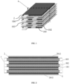
FIG. 1 is a schematic structural diagram of a laminated battery cell according to an embodiment of the present application. -
FIG. 2 is a schematic diagram of the cross-sectional structure of a laminated battery cell obtained by sectioning along a plane where a sectioning line as shown inFIG. 1 is located. -
FIG. 3 is a schematic structural diagram of a functional electrode sheet according to an embodiment of the present application. -
FIG. 4 is a schematic structural diagram of a protection assembly according to an embodiment of the present application. -
FIG. 5 is a schematic structural diagram of a protection assembly according to another embodiment of the present application. - 1: electrode sheet assembly; 2: protection assembly; 101: functional electrode sheet; 102: negative electrode sheet; 103: separator; 104: positive tab; 105: negative tab; 1011: first current collector; 1012: first protective layer; 1013: active layer; 2011: second current collector; 2012: second protective layer; 2013: second active layer.
- In order to make the purpose, technical solutions and advantages of the present application clearer, the technical solutions in the embodiments of the present application will be clearly and completely described below in combination with the embodiments and drawings of the present application. Obviously, the described embodiments are only part of the embodiments of the present application, not all of the embodiments. Based on the embodiments in this application, all other embodiments obtained by those skilled in the art without doing any creative work shall fall within the scope of protection of this application.
- Please refer to
FIGs 1 to 5 , a laminated battery cell provided in the present application includes an electrode sheet assembly 1 and aprotection assembly 2, where theprotection assembly 2 is located on the surface of an outer electrode sheet of the electrode sheet assembly 1; the electrode sheet assembly 1 includes at least onefunctional electrode sheet 101, thefunctional electrode sheet 101 includes a firstcurrent collector 1011, a firstprotective layer 1012 and aactive layer 1013, and the firstprotective layer 1012 is located between the firstcurrent collector 1011 and theactive layer 1013; theprotection assembly 2 includes a secondcurrent collector 2011 and a secondprotective layer 2012, and the secondprotective layer 2012 is away from the electrode sheet assembly 1; the firstprotective layer 1012 and the secondprotective layer 2012 each independently includes a conductive particle and a binder. - In the present application, the laminated battery cell includes the electrode sheet assembly 1 and the
protection assembly 2 which are laminated, where the electrode sheet assembly 1 has two opposite outer sides in the laminating direction of the laminated battery cell, and theprotection assembly 2 is located on the outer side of the electrode sheet assembly 1. - The number of the
protection assembly 2 is one or two. According to the number of theprotection assembly 2, theprotection assembly 2 is selected to be disposed on one side or both sides of the electrode sheet assembly 1. For example, when the number of theprotection assembly 2 is one, theprotection assembly 2 is located at any one of outer sides of the electrode sheet assembly 1; when the number ofprotection assembly 2 is two, twoprotection assemblies 2 are respectively disposed on two outer sides of the electrode sheet assembly 1. Theprotection assembly 2 functions to protect the electrode sheet assembly; and theprotection assembly 2 is separated from the electrode sheet assembly 1 by aseparator 103. - The electrode sheet assembly of the present application includes electrode sheets laminated in sequence, which are separated by the
separator 103. The electrode sheets are divided into a functional electrode sheet and a non-functional electrode sheet depending on whether to set the firstprotective layer 101. The number of thefunctional electrode sheet 101 is one or more. Eachfunctional electrode sheet 101 includes a firstcurrent collector 1011. The firstcurrent collector 1011 has two largest surfaces, and the firstprotective layer 1012 and theactive layer 1013 are disposed on the largest surfaces. The current collector of the non-functional electrode sheet is provided with only an active layer, and no protective layer. - In the
functional electrode sheet 101, theactive layer 1013 is disposed on one side or on both sides, and correspondingly, the firstprotective layer 1012 is disposed on one side or on both sides, as long as the firstprotective layer 1012 is located between theactive layer 1013 and the firstcurrent collector 1011. - The
protection assembly 2 includes a secondcurrent collector 2011 having two largest surfaces, and a secondprotective layer 2012 is disposed on the largest surface. The secondprotective layer 2012 is located on the surface of the secondcurrent collector 2011 away from the electrode sheet assembly 1. In order to further improve the capacity of the battery, a secondactive layer 2013 may be coated on the surface of the secondcurrent collector 2011 close to the electrode sheet assembly 1. In this case, the second protective layer may also be disposed between the secondactive layer 2013 and the secondcurrent collector 2011. - The first
protective layer 1012 and the secondprotective layer 2012 each independently include a conductive particle and a binder and 0% to 40% of non-conductive particle. Preferably, the firstprotective layer 1012 and the secondprotective layer 2012 are each composed of the conductive particle and the binder. The conductive particle provides the firstprotective layer 1012 and the secondprotective layer 2012 with a good conductive network. The binder can ensure that the firstprotective layer 1012 and the secondprotective layer 2012 are fixedly bonded to the firstcurrent collector 1011 and the secondcurrent collector 2011. - The applicant has found through research that the first
protective layer 1012 and the secondprotective layer 2012 can play a role of physical isolation when the battery suffers from mechanical damage, so that the current collectors in the electrode sheet assembly 1 and theprotection assembly 2 are not easily exposed, and the current collectors inside the laminated battery cell will be prevented from contacting with the active layer or current collector of the adjacent electrode sheet, thereby reducing the possibility of short circuit and significantly improving the safety performance of the battery. At the same time, the conductive particle makes the firstprotective layer 1012 and the secondprotective layer 2012 conductive, which can ensure smooth electronic conduction between the active layer and the current collector, so that the battery has excellent safety performance and good cycle performance. - In order to further improve the capacity of the battery, the second
active layer 2013 may be coated on the surface of the secondcurrent collector 2011 close to the electrode sheet assembly 1. At this point, a second protective layer may also be disposed between the secondactive layer 2013 and the secondcurrent collector 2011. - In the present application, there is no limitation on the peeling force between the first
protective layer 1012 and the firstcurrent collector 1011, and the peeling force between the firstprotective layer 1012 and the firstactive layer 1013, which can be adjusted according to actual needs. In a preferred embodiment, the peeling force between the firstprotective layer 1012 and the firstcurrent collector 1011 is greater than the peeling force between the firstprotective layer 1012 and the firstactive layer 1013, which can further reduce the possibility of the short circuit of battery due to the firstcurrent collector 1011 contacting with the firstactive layer 1013. - By adjusting the type and amount of the binders in the first
protective layer 1012 and the firstactive layer 1013, the peeling force between the firstprotective layer 1012 and the firstcurrent collector 1011 and the peeling force between the firstprotective layer 1012 and the firstactive layer 1013 can be controlled. - Specifically, when the types of binders in the first
protective layer 1012 and the firstactive layer 1013 are the same, by controlling the content of the binder in the firstprotective layer 1012 to be greater than the content of the binder in the firstactive layer 1013, the peeling force between the firstprotective layer 1012 and the firstcurrent collector 1011 is greater than the peeling force between the firstprotective layer 1012 and the firstactive layer 1013. - When the content of the binders in the first
protective layer 1012 and the firstactive layer 1013 is the same, selecting a binder with relatively stronger adhesion to add to the firstprotective layer 1012, and adding a binder with relatively weaker adhesion to add to the firstactive layer 1013, the peeling force between the firstprotective layer 1012 and the firstcurrent collector 1011 is greater than the peeling force between the firstprotective layer 1012 and the firstactive layer 1013. - In the present application, there is no limitation on the thickness of the first
protective layer 1012 and the secondprotective layer 2012, which can be adjusted according to actual conditions. In a preferred embodiment, the thickness of the firstprotective layer 1012 is A, and the thickness of the secondprotective layer 2012 is B, satisfying A≤B, which is more conducive to improving the safety of the battery. - As the thickness of the first
protective layer 1012 and the thickness of the secondprotective layer 2012 increase, the safety performance of the lithium-ion battery can be improved accordingly, but at the same time it will also lead to a corresponding decrease in the volume energy density of the battery. In order to take into account both the safety performance and volume energy density of the lithium-ion battery, in a preferred embodiment, the thickness of the firstprotective layer 1012 and the thickness of the secondprotective layer 2012 are each independently 1µm-10µm, preferably 2µm-5µm. - In the present application, the provision of the first
protective layer 1012 and the secondprotective layer 2012 may lead to an increase in battery impedance. In order to avoid the increase in the battery impedance, the applicant has found that when the resistance of each of the firstprotective layer 1012 and the secondprotective layer 2012 is 10mΩ-2000mΩ, more preferably 100m Ω -1000m Ω, the battery can still maintain good cycle performance. Where, the resistance of the firstprotective layer 1012 and the resistance of the secondprotective layer 2012 refer to the resistance values through the thickness of the firstprotective layer 1012 and the secondprotective layer 2012, respectively. - The resistance of the first
protective layer 1012 and the secondprotective layer 2012 can be controlled by selecting conductive particles with different resistivities and controlling the content of the conductive particle in the firstprotective layer 1012 and the secondprotective layer 2012 and so on. - In some embodiments, the resistivity of the conductive particle can be controlled to be 1-100 Ω·cm by controlling the type and particle size of the conductive particle.
- In order to achieve the coating of the first
protective layer 1012 and the secondprotective layer 2012 on the current collector, and to enable the conductive particles to be more densely distributed on the firstprotective layer 1012 and the secondprotective layer 2012, thereby making the lithium-ion battery have both good energy density and safety performance, the average particle size Dv50 of the conductive particle is 0.05-5µm, preferably 0.1-1µm in the present application. - The conductive particle contains a conductive material. When the content of the conductive material is low, it is not conducive to the cycle performance of the battery; when the content of the conductive material is high, the conductive particle is prone to agglomeration and is difficult to evenly disperse in the protective layer. The applicant has found through research that when the conductive particle is an inorganic filler with its surface coated with a conductive coating layer, the conductive coating layer provides the protective layer with a good conductive network, and the excellent dispersibility of the inorganic filler itself provides the conductive particle with good dispersibility. This can further the physical isolation and conductive properties of the protective layer.
- Specifically, the conductive coating layer has conductivity and is made of the conductive material. At least a part of the conductive coating layer constitutes the outermost layer of the conductive particle, as long as the conductive coating layer covers at least a part of the inorganic filler. In order to obtain better conductive property, the higher the coverage, the better it is.
- The conductive coating layer includes at least one of tin oxide, indium oxide, ATO, FTO, ITO, AZO, and carbon materials, preferably at least one of ATO, FTO, ITO, and AZO, and more preferably ATO. Among them, ATO refers to antimony-doped tin oxide, in which the antimony doping amount is 0-30%; FTO refers to fluorine-doped tin oxide, in which the fluorine doping amount is 0-10%; ITO refers to tin-doped indium oxide, in which the tin doping amount is 0-30%; AZO refers to aluminum-doped zinc oxide, in which the aluminum doping amount is ≤20%.
- The inorganic filler has the characteristics of high mechanical strength, good stability and good heat resistance. In the present application, there is no limitation on the specific type of the inorganic filler. In a preferred embodiment, the inorganic filler includes at least one of aluminum oxide, magnesium oxide, titanium oxide, zinc oxide, silicon oxide, boehmite, cobalt oxide, iron phosphate, lithium iron phosphate, lithium nickel cobalt manganese oxide, and lithium iron manganese phosphate.
- Controlling the mass content of the conductive coating layer in the conductive particle can further ensure that the lithium-ion battery has both good conductivity and safety performance. In a preferred embodiment, when the conductive coating layer accounts for 2% to 40% of the mass content of the conductive particle, the battery has relatively balanced safety performance and cycle performance.
- In the present application, no particular limitation is imposed on the type of binder, as long as it can ensure effective bonding between the protective layer and the current collector. In a preferred embodiment, the binder includes at least one of polyvinylidene fluoride (PVDF), acrylic modified PVDF, polyacrylate polymer, polyimide, styrene butadiene rubber, and styrene acrylic rubber.
- Taking into account the safety performance and cycle performance of lithium-ion battery, in the present application the content of conductive particle and the content of binder in each of the first protective layer and the second protective layer are also made a limitation. Specifically, the thickness of the first protective layer and the second protective layer independently include 40% to 98% of the conductive particle, 2% to 30% of the binder and 0% to 40% of the non-conductive particle based on a mass content.
- In the present application, in addition to the conductive particle and the binder included, the strength of the conductivity of the protective layer may be adjusted by adding other conductive agents or non-conductive agents. For example, a non-conductive agent such as alumina ceramic may be additionally added to reduce the conductivity of the protective layer, and a conductive agent such as carbon nanotubes may be additionally added to increase the conductivity of the protective layer. It should be noted that the above additional additives are not necessary for the protective layer of the present application.
- In the present application, the functional electrode sheet in the electrode sheet assembly is the negative electrode sheet and/or the positive electrode sheet; and the electrode sheet of the protection assembly is the negative electrode sheet and/or the positive electrode sheet.
- In an embodiment as shown in
FIG. 2 , allfunctional electrode sheets 101 in the electrode sheet assembly 1 are positive electrode sheets, the composition of thenegative electrode sheet 102 in the electrode sheet assembly can refer to conventional negative electrode sheets in the art, and theprotection assemblies 2 are all positive electrode sheets. - In the present application, there are no limitations on the material of the active layer, which may include an active material, a conductive agent, a binder and other components according to conventional compositions in the art. Among them, the component such as the active material, the conductive agent, and the binder may all be selected from conventional materials in the art.
- Taking the positive electrode sheet as an example, the positive electrode active material includes one or more of lithium cobaltate, lithium nickel cobalt manganese oxide, lithium nickel cobalt aluminum oxide, lithium iron phosphate, and lithium manganate; the conductive agent includes one or more of conductive carbon black, carbon nanotubes, conductive graphite, and graphene; the binder includes one or more of polyvinylidene fluoride (PVDF), acrylic modified PVDF, polyacrylate polymer, polyimide, styrene-butadiene rubber, and styrene-propylene rubber.
- The functional electrode sheet of the present application can be prepared by conventional technical means in the field. Specifically, the raw materials constituting the first protective layer can be uniformly dispersed in a solvent to obtain a protective layer slurry; the raw materials constituting the active layer can be uniformly dispersed in a solvent to obtain an active layer slurry; then the protective layer slurry is coated on at least one surface of the first current collector and dried to obtain the first protective layer; and then the active layer slurry is coated on the first protective layer, and dried to obtain the functional electrode sheet of the present application.
- In the present application, there is no specific limitation the coating method, and any coating method such as gravure coating, extrusion coating, spray coating, screen printing, etc. can be used to coat the protective layer slurry and the active layer slurry.
- The lithium-ion battery provided in the present application includes the above-mentioned laminated battery cell, and the lithium-ion battery can be prepared by conventional methods in the art. Specifically, the laminated battery cell can be further subjected to processes such as baking, liquid injection, formation, and packaging to obtain the above-mentioned lithium-ion battery.
- In this application, setting the first protective layer and the second protective layer can play a role of physical isolation when the battery is mechanically damaged, so that the current collectors in the electrode sheet assembly 1 and the
protection assembly 2 are not easily exposed, and the current collector inside the laminated battery cell are prevented from contacting with the active layer or current collector of the adjacent electrode sheet, thereby reducing the possibility of short circuit and significantly improving the safety performance of the battery. At the same time, the conductive particles make the first protective layer and the second protective layer conductive, which can ensure smooth electronic conduction between the active layer and the current collector, so that the battery has excellent safety performance and good cycle performance. - Due to the inclusion of the above positive electrode sheet, the lithium-ion battery of the present application also has excellent safety performance and good cycle performance.
- In order to make the purpose, technical solutions and advantages of the present application clearer, the technical solutions in the embodiments of the present application will be clearly and completely described below in combination with the embodiments of the present application. Obviously, the described embodiments are only part of the embodiments of the present application, not all of the embodiments. Based on the embodiments in this application, all other embodiments obtained by those skilled in the art without doing any creative work shall fall within the scope of protection of this application.
- In the following, the positive electrode sheet and lithium-ion battery provided by the present application are illustrated in detail through specific examples and comparative examples, where the test method of electrode peeling force is as follows: cutting the positive electrode sheet into small pieces with a length of 240 mm and a width of 30 mm; cutting the NITTO No. 5000NS tape into small pieces according to the specification of a length of 200 mm and a width of 24 mm; sticking one side of the small piece of tape to a steel plate (260 mm * 50 mm), and sticking the small piece of positive electrode sheet to the other side of the small piece of tape, thereby ensuring that the small piece of positive electrode sheet completely covers the small piece of tape; using a hand-held roller (diameter of 95mm, width of 45mm, weight of 2kg) to roll back and forth for 3 times to stick the small piece of positive electrode sheet and the small piece of tape together, and then using a tensile machine (tensile machine model Dongguan Kejian KJ-1065 series) for testing (180-degree peeling), where the testing equipment automatically records the tensile force value that changes with the peeling displacement and draws a curve of the tensile force value changing with the peeling displacement, the horizontal axis being the peeling displacement and the vertical axis being the tensile force value. The tensile force value when the curve is flat and the peeling displacement is greater than 5mm is the peeling force.
- Since the peeling force between the protective layer and the current collector is greater than the peeling force between the protective layer and the active material layer, when the positive electrode sheet is subjected to a peeling force test, peeling usually occurs at the interface between the active material and the protective layer. However, this test phenomenon also shows that the peeling force between the protective layer and the current collector is greater than the peeling force between the protective layer and the active material layer.
- The resistivity of a protective layer is determined as follows: a positive electrode current collector is placed on a bulk resistance meter with a probe diameter of 15 mm, and the resistance of the positive electrode current collector is measured as R1, and then the positive electrode current collector with a positive electrode protective layer is placed on the bulk resistance meter, and the total resistance of the positive electrode protective layer and the positive electrode current collector is measured as R2, where the resistance of the positive electrode protective layer is expressed as: R=R2-R1.
- The method for determining the resistivity of the conductive particle is as follows: the resistivity of the conductive particle is tested using a powder resistance tester, the test pressure of the powder being set to 20KN.
- The method for determining an average particle size of the conductive particle is as follows: using a laser particle size tester to test a particle size distribution of the conductive particle, and calculating the particle size from small to large, where the particle size when the sum of the volumes of the particles accounts for 50% of the total volume of the particles is referred to as the average particle size.
- The preparation of the laminated battery cell and the lithium-ion battery of this embodiment include the following steps.
-
- 1) 95wt% ATO-coated TiO2 as a conductive particle (ATO accounts for 10% of the conductive particle) is mixed with 5wt% PVDF to give a mixture, and NMP is added and stirred to obtain a positive electrode protective layer slurry with a solid content of 40%.
- 2) 96wt% of lithium cobaltate, 1wt% of carbon black, 1wt% of carbon nanotubes, and 2wt% of PVDF are mixed to give a mixture, and NMP is added and stirred to obtain a positive electrode active layer slurry with a solid content of 70%, where the average particle size of ATO-coated TiO2 is 0.4µm.
- 3) The positive electrode protective layer slurry prepared in step 1) is coated on two functional surfaces of an aluminum foil (a thickness of 9µm) and dried to obtain a first protective layer, and then the positive electrode active layer slurry prepared in step 2) is coated on the first protective layer to obtain a functional electrode sheet.
- 4) The positive electrode protective layer slurry prepared in step 1) is coated on two functional surfaces of an aluminum foil (a thickness of 9µm) and dried to obtain second protective layer, and then the positive electrode active layer slurry prepared in step 2) is coated on the second protective layer on one surface to obtain a protection assembly.
- 5) A roller press is used for rolling the functional electrode sheet and the protection assembly, so that the single-sided thickness of the first protective layer on the functional electrode sheet is rolled to 3µm, the single-sided thickness of the second protective layer on the protection assembly is rolled to 3µm, and the single-sided thickness of the active layer is rolled to 45µm; and then the functional electrode sheet and the protection assembly are cut by using a slitting machine, and finally a
positive tab 104 is welded on the functional electrode sheet and the protection assembly and a protective tape is stuck. - 96wt% of artificial graphite, 1wt% of carbon black, 1.5wt% of styrene-butadiene rubber, and 1.5wt% of sodium carboxymethyl cellulose are mixed to give a mixture, and deionized water is added and stirred to obtain a negative electrode active layer slurry with a solid content of 40%; and the negative electrode active layer slurry is coated on the upper and lower surfaces of a copper foil (a thickness of 5µm) by an extrusion coating process, and dried to obtain the negative electrode sheet;
the negative electrode sheet obtained is rolled using a roller press, and then cut using a slitting machine. Finally, anegative tab 105 is welded on the cut negative electrode sheet, and a protective tape is stuck. - The functional electrode sheet, a separator, and the negative electrode sheet are laminated in sequence to obtain an electrode sheet assembly, and then the protection assembly, the separator, the electrode sheet assembly, the separator, and the protection assembly are laminated in sequence, and stuck with an adhesive tape for fixation to obtain the laminated battery cell;
where, the positive electrode active layer on the protection assembly is close to the electrode sheet assembly. -
- 1) A punching die is used for punching out an aluminum-laminated film, then the laminated battery cell is encapsulated with the punched aluminum-laminated film to obtain a battery cell, and baked until the moisture content is qualified; and an electrolyte is injected into the battery cell.
- 2) Using a lithium-ion battery formation equipment, the obtained battery cell is subjected to charging and discharging so as to harden the battery cell, and then the capacity of the battery cell is sorted out.
- 3) The battery cell is sealed for a second time and subjected to edge-folded to obtain the lithium-ion battery of this embodiment.
- Compared with Example 1, in the preparation of the positive electrode sheet, in step 5), "the single-sided thickness of the first protective layer is rolled to 3 µm, and the single-sided thickness of the second protective layer is rolled to 3 µm" in Example 1 is replaced by "the single-sided thickness of the first protective layer is rolled to 2 µm, and the single-sided thickness of the second protective layer is rolled to 2 µm " , and the other conditions remain unchanged;
in the preparation of the laminated battery cell, the functional electrode sheet and the protection assembly are replaced with the functional electrode sheet and the protection assembly prepared in this embodiment. - Compared with Example 1, in the preparation of the positive electrode sheet, in step 5), "the single-sided thickness of the first protective layer is rolled to 3 µm, and the single-sided thickness of the second protective layer is rolled to 3 µm" in Example 1 is replaced by "the single-sided thickness of the first protective layer is rolled to 1 µm, and the single-sided thickness of the second protective layer is rolled to 1 µm", and the other conditions remain unchanged;
in the preparation of the laminated battery cell, the functional electrode sheet and the protection assembly are replaced with the functional electrode sheet and the protection assembly prepared in this embodiment. - Compared with Example 1, in the preparation of the positive electrode sheet, in step 5), "the single-sided thickness of the first protective layer is rolled to 3 µm, and the single-sided thickness of the second protective layer is rolled to 3 µm" in Example 1 is replaced by "the single-sided thickness of the first protective layer is rolled to 4 µm, and the single-sided thickness of the second protective layer is rolled to 4 µm", and the other conditions remain unchanged;
in the preparation of the laminated battery cell, the functional electrode sheet and the protection assembly are replaced with the functional electrode sheet and the protection assembly prepared in this embodiment. - Compared with Example 1, in the preparation of the positive electrode sheet, in step 5), "the single-sided thickness of the first protective layer is rolled to 3 µm, and the single-sided thickness of the second protective layer is rolled to 3 µm" in Example 1 is replaced by "the single-sided thickness of the first protective layer is rolled to 5µm, and the single-sided thickness of the second protective layer is rolled to 5 µm", and the other conditions remain unchanged;
in the preparation of the laminated battery cell, the functional electrode sheet and the protection assembly are replaced with the functional electrode sheet and the protection assembly prepared in this embodiment. - Compared with Example 1, in the preparation of the positive electrode sheet, in step 5), "the single-sided thickness of the first protective layer is rolled to 3 µm, and the single-sided thickness of the second protective layer is rolled to 3 µm" in Example 1 is replaced by "the single-sided thickness of the first protective layer is rolled to 2 µm, and the single-sided thickness of the second protective layer is rolled to 3 µm " , and the other conditions remain unchanged;
in the preparation of the laminated battery cell, the functional electrode sheet and the protection assembly are replaced with the functional electrode sheet and the protection assembly prepared in this embodiment. - Compared with Example 1, in the preparation of the positive electrode sheet, in step 5), "the single-sided thickness of the first protective layer is rolled to 3 µm, and the single-sided thickness of the second protective layer is rolled to 3 µm" in Example 1 is replaced by "the single-sided thickness of the first protective layer is rolled to 2 µm, and the single-sided thickness of the second protective layer is rolled to 5 µm", and the other conditions remain unchanged;
in the preparation of the laminated battery cell, the functional electrode sheet and the protection assembly are replaced with the functional electrode sheet and the protection assembly prepared in this embodiment. - Compared with Example 1, in the preparation of the positive electrode sheet, in step 5), "the single-sided thickness of the first protective layer is rolled to 3 µm, and the single-sided thickness of the second protective layer is rolled to 3 µm" in Example 1 is replaced by "the single-sided thickness of the first protective layer is rolled to 2 µm, and the single-sided thickness of the second protective layer is rolled to 8 µm " , and the other conditions remain unchanged;
in the preparation of the laminated battery cell, the functional electrode sheet and the protection assembly are replaced with the functional electrode sheet and the protection assembly prepared in this embodiment. - Compared with Example 1, in the preparation of the positive electrode sheet, in step 5), "the single-sided thickness of the first protective layer is rolled to 3 µm, and the single-sided thickness of the second protective layer is rolled to 3 µm" in Example 1 is replaced by "the single-sided thickness of the first protective layer is rolled to 3µm, and the single-sided thickness of the second protective layer is rolled to 1 µm ", and the other conditions remain unchanged;
in the preparation of the laminated battery cell, the functional electrode sheet and the protection assembly are replaced with the functional electrode sheet and the protection assembly prepared in this embodiment. - Compared with Example 1, in the preparation of the positive electrode sheet, in step 5), "the single-sided thickness of the second protective layer is rolled to 3 µm" in Example 1 is replaced by "the single-sided thickness of the second protective layer is rolled to 2µm", and the other conditions remain unchanged;
in the preparation of the laminated battery cell, the functional electrode sheet and the protection assembly are replaced with the functional electrode sheet and the protection assembly prepared in this embodiment. - Compared with Example 1, in the preparation of the positive electrode sheet, in step 5), "the single-sided thickness of the first protective layer is rolled to 3 µm, and the single-sided thickness of the second protective layer is rolled to 3 µm" in Example 1 is replaced by "the single-sided thickness of the first protective layer is rolled to 15µm, and the single-sided thickness of the second protective layer is rolled to 15 µm", and the other conditions remain unchanged;
in the preparation of the laminated battery cell, the functional electrode sheet and the protection assembly are replaced with the functional electrode sheet and the protection assembly prepared in this embodiment. - Compared with Example 1, in the preparation of the positive electrode sheet, in step 1), "95wt% ATO-coated TiO2 as a conductive particle (ATO accounts for 10% of the conductive particle) is mixed with 5wt% PVDF to give a mixture" is replaced by "30wt% ATO-coated TiO2 and 60% TiO2 as a conductive particle (ATO accounts for 10% of the conductive particle) is mixed with 10wt% PVDF to give a mixture", and the other conditions remain unchanged;
in the preparation of the laminated battery cell, the functional electrode sheet and the protection assembly are replaced with the functional electrode sheet and the protection assembly prepared in this embodiment. - Compared with Example 1, in the preparation of the positive electrode sheet, the step 4) is replaced by "the positive electrode active layer slurry prepared in step 2) is coated on an aluminum foil (a thickness of 9µm) to obtain a protection assembly",
- in step 5), the "the single-side thickness of the first protective layer is rolled to 3µ m, and the single-side thickness of the second protective layer is rolled to 3µm" in Example 1 is replaced by "the single-side thickness of the first protective layer is rolled to 3µm", and the other conditions remain unchanged;
- in the preparation of the laminated battery cell, the functional electrode sheet and the protection assembly are replaced with the functional electrode sheet and the protection assembly prepared in this embodiment.
- Compared with Example 1, in the preparation of the positive electrode sheet, steps 3), 4), and 5) are replaced by "the positive electrode active layer slurry prepared in step 2) is coated on two functional surfaces of an aluminum foil (a thickness of 9 µm), and dried to obtain a positive electrode sheet; the positive electrode sheet obtained is rolled using a roller press until the single-side thickness of the active layer is 45 µm", and the other conditions remain unchanged;
in the preparation of the laminated battery cell, the functional electrode sheet and the protection assembly are replaced with the positive electrode sheet prepared in this embodiment. - Compared with Example 1, in the preparation of the positive electrode sheet, in step 1), "ATO-coated TiO2 as a conductive particle" in Example 1 is replaced with "ATO as a conductive particle", and the other conditions remain unchanged;
in the preparation of the laminated battery cell, the functional electrode sheet and the protection assembly are replaced with the functional electrode sheet and the protection assembly prepared in this embodiment. - The rest is the same as in Example 1.
- Compared with Example 1, in the preparation of the positive electrode sheet, in step 5), "the single-sided thickness of the first protective layer is rolled to 3 µm, and the single-sided thickness of the second protective layer is rolled to 3 µm" in Example 1 is replaced by "the single-sided thickness of the first protective layer is rolled to 0.5µm, and the single-sided thickness of the second protective layer is rolled to 0.5 µm", and the other conditions remain unchanged;
in the preparation of the laminated battery cell, the functional electrode sheet and the protection assembly are replaced with the functional electrode sheet and the protection assembly prepared in this embodiment. - Compared with Example 1, in the preparation of the positive electrode sheet, in step 1), "95wt% ATO-coated TiO2 as a conductive particle (ATO accounts for 10% of the conductive particle) is mixed with 5wt% PVDF to give a mixture" is replaced by "95wt% ATO-coated TiO2 as a conductive particle (ATO accounts for 60% of the conductive particle) is mixed with 5wt% PVDF to give a mixture", and the other conditions remain unchanged;
in the preparation of the laminated battery cell, the functional electrode sheet and the protection assembly are replaced with the functional electrode sheet and the protection assembly prepared in this embodiment. - The lithium-ion batteries of the above examples and comparative examples are tested for needle puncture qualification rate, screw extrusion qualification rate, capacity retention rate, and energy density. The test methods are as follows.
- Test method: fully charging the lithium-ion battery, and then placing it on a test bench of the needle puncture test equipment; and piercing a battery from the middle part of the battery with a tungsten steel needle having a diameter of 3mm and a needle tip length of 3.62mm at a speed of 100mm/s, where the battery will be considered as test qualification if it does not catch fire or explode. The qualification number/test number is the needle puncture qualification rate, and the test number is 30.
- Test method: the lithium-ion battery is fully charged and then placed on the test bench of the extrusion equipment, an M2*4 screw (a screw diameter of 2mm, a screw length of 4mm) is placed in the middle of the battery, then the extrusion equipment is started to press the extrusion plate down at a speed of 100mm/s, and the test is stopped when the extrusion force reaches 13KN, where the battery is considered as test qualification if it does not catch fire or explode. The qualification number/test number is the screw test qualification rate, and the test number is 30.
- Test method: At 45 ° C, the lithium-ion battery is subjected to charging and discharging at a rate of 1.5C charge/0.5C discharge, and the discharge capacity Q2 of the 500th charge and discharge and the discharge capacity Q1 of the first charge and discharge are recorded. The capacity retention rate = Q2/Q1×100%.
- Test method: the lithium-ion battery is charged to an upper-limit voltage of 4.45V, and then is discharged at 0.2C to a lower-limit voltage of 3.0V, where the discharge energy is recorded as E, and then the energy density of the lithium-ion battery is calculated using the following formula:

- The specific test results are shown in Table 1 and Table 2.
Table 1 Item First protective layer compositio n Second protective layer compositio n First protectiv e layer thicknes s Second protectiv e layer thickness Conductiv e particle coating layer ratio First protectiv e layer resistanc e mΩ second protectiv e layer resistanc e mΩ Needl e punct ure qualif icatio n rate Screw qualifica tion rate 45°C cycle capacity retentio n rate Energ y densit y (Wh/L ) Exam ple 1 95% ATO coated TiO2+5% PVDF 95% ATO coated TiO2+5% PVDF 3 3 10% 200 200 30/30 30/30 85.7% 690 Exam ple 2 95% ATO coated TiO2+5% PVDF 95% ATO coated TiO2+5% PVDF 2 2 10% 130 130 26/30 26/30 85.9% 692 Exam ple 3 95% ATO coated TiO2+5% PVDF 95% ATO coated TiO2+5% PVDF 1 1 10% 60 60 23/30 22/30 86% 695 Exam ple 4 95% ATO coated TiO2+5% PVDF 95% ATO coated TiO2+5% PVDF 4 4 10% 280 280 30/30 30/30 85.6% 688 Exam ple 5 95% ATO coated TiO2+5% PVDF 95% ATO coated TiO2+5% PVDF 5 5 10% 310 310 30/30 30/30 85.4% 685 Exam ple 6 95% ATO coated TiO2+5% PVDF 95% ATO coated TiO2+5% PVDF 2 3 10% 130 200 28/30 27/30 85.9% 691 Exam ple 7 95% ATO coated TiO2+5% PVDF 95% ATO coated TiO2+5% PVDF 2 5 10% 130 310 30/30 20/30 85.9% 691 Exam ple 8 95% ATO coated TiO2+5% PVDF 95% ATO coated TiO2+5% PVDF 2 8 10% 130 500 30/30 30/30 85.9% 690 Exam ple 9 95% ATO coated TiO2+5% PVDF 95% ATO coated TiO2+5% PVDF 3 1 10% 200 60 25/30 24/30 85.7% 690 Table 2 Item First protective layer compositio n Second protective layer compositio n First protectiv e layer thickness Second protecti ve layer thicknes s Conductiv e particle coating layer ratio First protecti ve layer resistanc e mΩ second protectiv e layer resistanc e mΩ Needle punctu re qualifi cation rate Screw qualifica tion rate 45°C cycle capacit y retentio n rate Energ y densit y (Wh/L ) Exam ple 10 95% ATO coated TiO2+5% PVDF 95% ATO coated TiO2+5% PVDF 3 2 10% 200 130 27/30 26/30 85.7% 691 Exam ple 11 95% ATO coated TiO2+5% PVDF 95% ATO coated TiO2+5% PVDF 15 15 10% 1000 1000 30/30 30/30 84.2% 655 Exam ple 12 30% ATO coated TiO2+60% TiO2+10% PVDF 30%ATO coated TiO2+60Ti O2+10%P VDF 3 3 10% 3000 3000 30/30 30/30 67% 690 Comp arative Exam ple 1 95% ATO coated TiO2+5% PVDF / 3 0 10% 200 0 18/30 17/30 85.7% 691 Comp arative Exam ple 2 / / 0 0 0/30 0/30 84% 700 Comp arative Exam ple 3 95% ATO+5% PVDF 95% ATO+5% PVDF 3 3 / 8 8 6/30 5/30 86.9% 690 Comp arative Exam ple 4 95% ATO coated TiO2+5% PVDF 95% ATO coated TiO2+5% PVDF 0.5 0.5 10% 30 30 12/30 13/30 86.2% 698 Comp arative Exam ple 5 95% ATO coated TiO2+5% PVDF 95% ATO coated TiO2+5% PVDF 3 3 60% 20 20 16/30 15/30 86.6% 690 - According to Table 1 and Table 2, by comparing Examples 1 to 12 with Comparative Examples 1 and 2, it can be seen that adding the first protective layer and the second protective layer can significantly improve the safety performance of the battery.
- By comparing Example 1 with Examples 9 and 10, it can be seen that when the thickness of the second protective layer is smaller than that of the first protective layer, the safety of the battery will be reduced. When the thickness of the first protective layer remains unchanged, as the thickness of the second protective layer increases, the safety performance of the battery is also significantly improved. By comparing Example 2 with Examples 6, 7, and 8, it can be seen that when the thickness of the second protective layer is greater than or equal to the thickness of the first protective layer, the safety of the battery is improved. When the thickness of the first protective layer remains unchanged, as the thickness of the second protective layer increases, the safety performance of the battery is also significantly improved.
- By comparing Example 1 and Comparative Example 3, it can be seen that the use of an inorganic filler having a conductive coating layer as a conductive material can further reduce the probability of short circuit between the positive electrode current collector and the negative electrode active layer, improving the safety performance of the battery, and at the same time having good cycle performance of the battery.
- By comparing Example 1 and Comparative Example 4, it can be seen that as the thickness of the protective layer increases, the safety performance of the lithium-ion battery can also be improved accordingly. When the thickness of the protective layer does not exceed 0.5µm, it is difficult to achieve the protective effect.
- By comparing Example 1 with Comparative Example 5, it can be seen that when the conductive coating layer accounts for 2% to 40% of the mass content of the conductive particle, the battery has relatively balanced safety performance and cycle performance.
- Finally, it should be noted that the above embodiments are only used to illustrate the technical solutions of the present application, rather than to limit them. Although the present application has been described in detail with reference to the aforementioned embodiments, those skilled in the art should understand that they can still modify the technical solutions described in the aforementioned embodiments, or replace some or all of the technical features therein with equivalents. However, these modifications or replacements do not cause the essence of the corresponding technical solutions to deviate from the scope of the technical solutions of the embodiments of the present application.
Claims (12)
- A laminated battery cell, comprising an electrode sheet assembly and a protection assembly, wherein the protection assembly is located on a surface of an outer electrode sheet of the electrode sheet assembly;the electrode sheet assembly comprises at least one functional electrode sheet, the functional electrode sheet comprises a first current collector, a first protective layer and an active layer, and the first protective layer is located between the first current collector and the active layer;the protection assembly comprises a second current collector and a second protective layer, and the second protective layer is away from the electrode sheet assembly; a thickness of the first protective layer and a thickness of the second protective layer are each greater than 0.5µm;the first protective layer and the second protective layer each independently comprise a conductive particle and a binder; the conductive particle is an inorganic filler with a conductive coating layer on its surface; the conductive coating layer accounts for 2% to 40% of a mass content of the conductive particle.
- The laminated battery cell according to claim 1, wherein at least a portion of the conductive coating layer constitutes an outermost layer of the conductive particle.
- The laminated battery cell according to claim 1 or 2, wherein the conductive coating layer covers at least a portion of the inorganic filler.
- The laminated battery cell according to any one of claims 1 to 3, wherein a thickness of the first protective layer is A, a thickness of the second protective layer is B, and A is less than or equal to B.
- The laminated battery cell according to any one of claims 1 to 4, wherein a thickness of the first protective layer and a thickness of the second protective layer are each independently 1µm to 10µm.
- The laminated battery cell according to any one of claims 1 to 5, wherein the first protective layer and the second protective layer each independently comprise 40% to 98% of the conductive particle, 2% to 30% of the binder, and 0% to 40% of the non-conductive particle by mass content.
- The laminated battery cell according to any one of claims 1 to 6, wherein the first protective layer and the second protective layer each independently have a resistance of 10-2000mΩ.
- The laminated battery cell according to any one of claims 1 to 6, wherein a resistivity of the conductive particle is 1 to 100Ω•cm.
- The laminated battery cell according to any one of claims 1 to 6, wherein an average particle size of the conductive particle is 0.05-5µm.
- The laminated battery cell according to claim 1, wherein the conductive coating layer comprises at least one of tin oxide, indium oxide, ATO, FTO, ITO, and carbon material.
- The laminated battery cell according to any one of claims 7 to 10, wherein the inorganic filler comprises at least one of aluminum oxide, magnesium oxide, titanium oxide, zinc oxide, silicon oxide, boehmite, cobalt oxide, iron phosphate, lithium iron phosphate, lithium nickel cobalt manganese oxide, and lithium iron manganese phosphate.
- A lithium-ion battery, comprising the laminated battery cell according to any one of claims 1 to 11.
Applications Claiming Priority (2)
| Application Number | Priority Date | Filing Date | Title |
|---|---|---|---|
| CN202211304492 | 2022-10-24 | ||
| PCT/CN2023/079998 WO2024087450A1 (en) | 2022-10-24 | 2023-03-07 | Stacked battery cell and lithium ion battery |
Publications (3)
| Publication Number | Publication Date |
|---|---|
| EP4517910A1 true EP4517910A1 (en) | 2025-03-05 |
| EP4517910A4 EP4517910A4 (en) | 2025-10-01 |
| EP4517910B1 EP4517910B1 (en) | 2026-05-06 |
Family
ID=90768962
Family Applications (1)
| Application Number | Title | Priority Date | Filing Date |
|---|---|---|---|
| EP23881053.5A Active EP4517910B1 (en) | 2022-10-24 | 2023-03-07 | Stacked battery cell and lithium ion battery |
Country Status (4)
| Country | Link |
|---|---|
| US (1) | US20250054991A1 (en) |
| EP (1) | EP4517910B1 (en) |
| CN (1) | CN117936925A (en) |
| WO (1) | WO2024087450A1 (en) |
Family Cites Families (4)
| Publication number | Priority date | Publication date | Assignee | Title |
|---|---|---|---|---|
| CN1285133C (en) * | 2002-09-27 | 2006-11-15 | Tdk株式会社 | Lithium secondary battery |
| JP6783146B2 (en) * | 2015-01-05 | 2020-11-11 | 株式会社エンビジョンAescエナジーデバイス | Electrodes and lithium-ion secondary batteries using them |
| CN112582580A (en) * | 2020-12-14 | 2021-03-30 | 珠海冠宇电池股份有限公司 | Positive plate and lithium ion battery comprising same |
| CN114156429A (en) * | 2021-11-29 | 2022-03-08 | 珠海冠宇电池股份有限公司 | Pole piece and lithium ion battery |
-
2023
- 2023-03-07 EP EP23881053.5A patent/EP4517910B1/en active Active
- 2023-03-07 WO PCT/CN2023/079998 patent/WO2024087450A1/en not_active Ceased
- 2023-10-23 CN CN202311376093.3A patent/CN117936925A/en active Pending
-
2024
- 2024-10-28 US US18/929,406 patent/US20250054991A1/en active Pending
Also Published As
| Publication number | Publication date |
|---|---|
| EP4517910A4 (en) | 2025-10-01 |
| WO2024087450A1 (en) | 2024-05-02 |
| EP4517910B1 (en) | 2026-05-06 |
| CN117936925A (en) | 2024-04-26 |
| US20250054991A1 (en) | 2025-02-13 |
Similar Documents
| Publication | Publication Date | Title |
|---|---|---|
| EP4086982A1 (en) | Positive electrode plate and lithium ion battery | |
| EP3930044B1 (en) | Positive electrode sheet and lithium ion battery including the same | |
| CN109755463B (en) | Electrode pole piece, electrochemical device and safety coating | |
| EP3506403B1 (en) | Current collector, electrode plate of the same and battery | |
| CN109755466B (en) | Positive pole piece, electrochemical device and safety coating | |
| EP4216320A2 (en) | Battery | |
| EP4503169A1 (en) | Positive sheet and lithium ion battery | |
| WO2022242255A1 (en) | Electrode plate, preparation method, composite current collector, battery and electronic device | |
| WO2022037092A1 (en) | Current collector, pole piece and battery | |
| EP3573145B1 (en) | Battery and method for preparing the same | |
| WO2023093576A1 (en) | Pole piece and lithium ion battery | |
| CN109755670B (en) | Electrode pole piece, electrochemical device and safety coating | |
| CN218513484U (en) | Positive electrode sheet, electrode assembly, battery, and vehicle | |
| CN109755464B (en) | Electrode pole piece, electrochemical device and safety coating | |
| CN111725558B (en) | Solid electrolyte and all-solid-state lithium metal battery thereof | |
| WO2021189481A1 (en) | Positive electrode piece and electrochemical apparatus comprising same, and electronic apparatus | |
| WO2025036075A1 (en) | Electrode sheet, battery cell and battery | |
| CN114976004B (en) | A negative electrode slurry, negative electrode sheet, lithium ion battery and preparation method thereof | |
| EP4024535A1 (en) | Positive electrode plate, preparation method therefor and use thereof | |
| EP4579817A1 (en) | Positive electrode sheet, secondary battery and electric device | |
| WO2024222100A1 (en) | Positive electrode sheet and preparation method therefor, lithium-ion battery, battery pack and electric device | |
| KR101693359B1 (en) | Aluminum current collector, electrode comprising the Aluminum current collector, and electrochemical device comprising the electrode | |
| US20250140859A1 (en) | Electrode assembly and battery | |
| EP4718505A1 (en) | Positive electrode and preparation method thereof and battery | |
| CN109755465B (en) | Electrode pole piece, electrochemical device and safety coating |
Legal Events
| Date | Code | Title | Description |
|---|---|---|---|
| STAA | Information on the status of an ep patent application or granted ep patent |
Free format text: STATUS: THE INTERNATIONAL PUBLICATION HAS BEEN MADE |
|
| PUAI | Public reference made under article 153(3) epc to a published international application that has entered the european phase |
Free format text: ORIGINAL CODE: 0009012 |
|
| STAA | Information on the status of an ep patent application or granted ep patent |
Free format text: STATUS: REQUEST FOR EXAMINATION WAS MADE |
|
| 17P | Request for examination filed |
Effective date: 20241125 |
|
| AK | Designated contracting states |
Kind code of ref document: A1 Designated state(s): AL AT BE BG CH CY CZ DE DK EE ES FI FR GB GR HR HU IE IS IT LI LT LU LV MC ME MK MT NL NO PL PT RO RS SE SI SK SM TR |
|
| A4 | Supplementary search report drawn up and despatched |
Effective date: 20250903 |
|
| RIC1 | Information provided on ipc code assigned before grant |
Ipc: H01M 10/0585 20100101AFI20250828BHEP Ipc: H01M 10/42 20060101ALI20250828BHEP |
|
| GRAP | Despatch of communication of intention to grant a patent |
Free format text: ORIGINAL CODE: EPIDOSNIGR1 |
|
| STAA | Information on the status of an ep patent application or granted ep patent |
Free format text: STATUS: GRANT OF PATENT IS INTENDED |
|
| RIC1 | Information provided on ipc code assigned before grant |
Ipc: H01M 10/0585 20100101AFI20251128BHEP Ipc: H01M 10/42 20060101ALI20251128BHEP |
|
| DAV | Request for validation of the european patent (deleted) | ||
| DAX | Request for extension of the european patent (deleted) | ||
| INTG | Intention to grant announced |
Effective date: 20251210 |
|
| GRAS | Grant fee paid |
Free format text: ORIGINAL CODE: EPIDOSNIGR3 |
|
| GRAA | (expected) grant |
Free format text: ORIGINAL CODE: 0009210 |
|
| STAA | Information on the status of an ep patent application or granted ep patent |
Free format text: STATUS: THE PATENT HAS BEEN GRANTED |