EP4517738A1 - Percussion instrument and musical sound generation method - Google Patents
Percussion instrument and musical sound generation method Download PDFInfo
- Publication number
- EP4517738A1 EP4517738A1 EP24190087.7A EP24190087A EP4517738A1 EP 4517738 A1 EP4517738 A1 EP 4517738A1 EP 24190087 A EP24190087 A EP 24190087A EP 4517738 A1 EP4517738 A1 EP 4517738A1
- Authority
- EP
- European Patent Office
- Prior art keywords
- light
- lever
- sensor
- percussion instrument
- operator
- Prior art date
- Legal status (The legal status is an assumption and is not a legal conclusion. Google has not performed a legal analysis and makes no representation as to the accuracy of the status listed.)
- Pending
Links
Images



Classifications
-
- G—PHYSICS
- G10—MUSICAL INSTRUMENTS; ACOUSTICS
- G10H—ELECTROPHONIC MUSICAL INSTRUMENTS; INSTRUMENTS IN WHICH THE TONES ARE GENERATED BY ELECTROMECHANICAL MEANS OR ELECTRONIC GENERATORS, OR IN WHICH THE TONES ARE SYNTHESISED FROM A DATA STORE
- G10H3/00—Instruments in which the tones are generated by electromechanical means
- G10H3/12—Instruments in which the tones are generated by electromechanical means using mechanical resonant generators, e.g. strings or percussive instruments, the tones of which are picked up by electromechanical transducers, the electrical signals being further manipulated or amplified and subsequently converted to sound by a loudspeaker or equivalent instrument
- G10H3/14—Instruments in which the tones are generated by electromechanical means using mechanical resonant generators, e.g. strings or percussive instruments, the tones of which are picked up by electromechanical transducers, the electrical signals being further manipulated or amplified and subsequently converted to sound by a loudspeaker or equivalent instrument using mechanically actuated vibrators with pick-up means
- G10H3/146—Instruments in which the tones are generated by electromechanical means using mechanical resonant generators, e.g. strings or percussive instruments, the tones of which are picked up by electromechanical transducers, the electrical signals being further manipulated or amplified and subsequently converted to sound by a loudspeaker or equivalent instrument using mechanically actuated vibrators with pick-up means using a membrane, e.g. a drum; Pick-up means for vibrating surfaces, e.g. housing of an instrument
-
- G—PHYSICS
- G10—MUSICAL INSTRUMENTS; ACOUSTICS
- G10D—STRINGED MUSICAL INSTRUMENTS; WIND MUSICAL INSTRUMENTS; ACCORDIONS OR CONCERTINAS; PERCUSSION MUSICAL INSTRUMENTS; AEOLIAN HARPS; SINGING-FLAME MUSICAL INSTRUMENTS; MUSICAL INSTRUMENTS NOT OTHERWISE PROVIDED FOR
- G10D13/00—Percussion musical instruments; Details or accessories therefor
- G10D13/01—General design of percussion musical instruments
-
- G—PHYSICS
- G10—MUSICAL INSTRUMENTS; ACOUSTICS
- G10D—STRINGED MUSICAL INSTRUMENTS; WIND MUSICAL INSTRUMENTS; ACCORDIONS OR CONCERTINAS; PERCUSSION MUSICAL INSTRUMENTS; AEOLIAN HARPS; SINGING-FLAME MUSICAL INSTRUMENTS; MUSICAL INSTRUMENTS NOT OTHERWISE PROVIDED FOR
- G10D13/00—Percussion musical instruments; Details or accessories therefor
- G10D13/10—Details of, or accessories for, percussion musical instruments
- G10D13/25—Details of, or accessories for, percussion musical instruments for changing the sound or tone
-
- G—PHYSICS
- G10—MUSICAL INSTRUMENTS; ACOUSTICS
- G10D—STRINGED MUSICAL INSTRUMENTS; WIND MUSICAL INSTRUMENTS; ACCORDIONS OR CONCERTINAS; PERCUSSION MUSICAL INSTRUMENTS; AEOLIAN HARPS; SINGING-FLAME MUSICAL INSTRUMENTS; MUSICAL INSTRUMENTS NOT OTHERWISE PROVIDED FOR
- G10D13/00—Percussion musical instruments; Details or accessories therefor
- G10D13/10—Details of, or accessories for, percussion musical instruments
- G10D13/26—Mechanical details of electronic drums
-
- G—PHYSICS
- G10—MUSICAL INSTRUMENTS; ACOUSTICS
- G10H—ELECTROPHONIC MUSICAL INSTRUMENTS; INSTRUMENTS IN WHICH THE TONES ARE GENERATED BY ELECTROMECHANICAL MEANS OR ELECTRONIC GENERATORS, OR IN WHICH THE TONES ARE SYNTHESISED FROM A DATA STORE
- G10H1/00—Details of electrophonic musical instruments
- G10H1/02—Means for controlling the tone frequencies, e.g. attack or decay; Means for producing special musical effects, e.g. vibratos or glissandos
- G10H1/04—Means for controlling the tone frequencies, e.g. attack or decay; Means for producing special musical effects, e.g. vibratos or glissandos by additional modulation
- G10H1/053—Means for controlling the tone frequencies, e.g. attack or decay; Means for producing special musical effects, e.g. vibratos or glissandos by additional modulation during execution only
- G10H1/055—Means for controlling the tone frequencies, e.g. attack or decay; Means for producing special musical effects, e.g. vibratos or glissandos by additional modulation during execution only by switches with variable impedance elements
- G10H1/0553—Means for controlling the tone frequencies, e.g. attack or decay; Means for producing special musical effects, e.g. vibratos or glissandos by additional modulation during execution only by switches with variable impedance elements using optical or light-responsive means
-
- G—PHYSICS
- G10—MUSICAL INSTRUMENTS; ACOUSTICS
- G10H—ELECTROPHONIC MUSICAL INSTRUMENTS; INSTRUMENTS IN WHICH THE TONES ARE GENERATED BY ELECTROMECHANICAL MEANS OR ELECTRONIC GENERATORS, OR IN WHICH THE TONES ARE SYNTHESISED FROM A DATA STORE
- G10H1/00—Details of electrophonic musical instruments
- G10H1/44—Tuning means
-
- G—PHYSICS
- G10—MUSICAL INSTRUMENTS; ACOUSTICS
- G10H—ELECTROPHONIC MUSICAL INSTRUMENTS; INSTRUMENTS IN WHICH THE TONES ARE GENERATED BY ELECTROMECHANICAL MEANS OR ELECTRONIC GENERATORS, OR IN WHICH THE TONES ARE SYNTHESISED FROM A DATA STORE
- G10H1/00—Details of electrophonic musical instruments
- G10H1/46—Volume control
-
- G—PHYSICS
- G10—MUSICAL INSTRUMENTS; ACOUSTICS
- G10H—ELECTROPHONIC MUSICAL INSTRUMENTS; INSTRUMENTS IN WHICH THE TONES ARE GENERATED BY ELECTROMECHANICAL MEANS OR ELECTRONIC GENERATORS, OR IN WHICH THE TONES ARE SYNTHESISED FROM A DATA STORE
- G10H2220/00—Input/output interfacing specifically adapted for electrophonic musical tools or instruments
- G10H2220/155—User input interfaces for electrophonic musical instruments
- G10H2220/391—Angle sensing for musical purposes, using data from a gyroscope, gyrometer or other angular velocity or angular movement sensing device
-
- G—PHYSICS
- G10—MUSICAL INSTRUMENTS; ACOUSTICS
- G10H—ELECTROPHONIC MUSICAL INSTRUMENTS; INSTRUMENTS IN WHICH THE TONES ARE GENERATED BY ELECTROMECHANICAL MEANS OR ELECTRONIC GENERATORS, OR IN WHICH THE TONES ARE SYNTHESISED FROM A DATA STORE
- G10H2220/00—Input/output interfacing specifically adapted for electrophonic musical tools or instruments
- G10H2220/155—User input interfaces for electrophonic musical instruments
- G10H2220/405—Beam sensing or control, i.e. input interfaces involving substantially immaterial beams, radiation, or fields of any nature, used, e.g. as a switch as in a light barrier, or as a control device, e.g. using the theremin electric field sensing principle
- G10H2220/411—Light beams
-
- G—PHYSICS
- G10—MUSICAL INSTRUMENTS; ACOUSTICS
- G10H—ELECTROPHONIC MUSICAL INSTRUMENTS; INSTRUMENTS IN WHICH THE TONES ARE GENERATED BY ELECTROMECHANICAL MEANS OR ELECTRONIC GENERATORS, OR IN WHICH THE TONES ARE SYNTHESISED FROM A DATA STORE
- G10H2230/00—General physical, ergonomic or hardware implementation of electrophonic musical tools or instruments, e.g. shape or architecture
- G10H2230/045—Special instrument [spint], i.e. mimicking the ergonomy, shape, sound or other characteristic of a specific acoustic musical instrument category
- G10H2230/251—Spint percussion, i.e. mimicking percussion instruments; Electrophonic musical instruments with percussion instrument features; Electrophonic aspects of acoustic percussion instruments or MIDI-like control therefor
- G10H2230/275—Spint drum
- G10H2230/285—Spint drum tomtom, i.e. mimicking side-mounted drums without snares, e.g. in a drumkit
-
- G—PHYSICS
- G10—MUSICAL INSTRUMENTS; ACOUSTICS
- G10H—ELECTROPHONIC MUSICAL INSTRUMENTS; INSTRUMENTS IN WHICH THE TONES ARE GENERATED BY ELECTROMECHANICAL MEANS OR ELECTRONIC GENERATORS, OR IN WHICH THE TONES ARE SYNTHESISED FROM A DATA STORE
- G10H2230/00—General physical, ergonomic or hardware implementation of electrophonic musical tools or instruments, e.g. shape or architecture
- G10H2230/045—Special instrument [spint], i.e. mimicking the ergonomy, shape, sound or other characteristic of a specific acoustic musical instrument category
- G10H2230/251—Spint percussion, i.e. mimicking percussion instruments; Electrophonic musical instruments with percussion instrument features; Electrophonic aspects of acoustic percussion instruments or MIDI-like control therefor
- G10H2230/275—Spint drum
- G10H2230/305—Spint drum snare, i.e. mimicking using strands of snares made of curled metal wire, metal cable, plastic cable, or gut cords stretched across the drumhead, e.g. snare drum, side drum, military drum, field drum
Definitions
- the disclosure relates to a percussion instrument and a musical sound generation method, and particularly relates to a percussion instrument and a musical sound generation method capable of generating various musical sounds.
- Patent Document 1 discloses a percussion instrument able to bring a snare wire 29 into contact with or separate the snare wire 29 from the lower surface of a resonance head 22 through an operation that rotates a lever 34.
- a sensor 48 provided on the lower surface of the resonance head 22
- whether the snare wire 29 contacts the resonance head 22 is detected.
- different musical sounds are generated when the resonance head 22 and the snare wire 29 are in contact and when the resonance head 22 and the snare wire 29 are separated. Accordingly, various musical sounds can be generated.
- Patent Document 1 Japanese Laid-open No. 2017-194585 (see, for example, para. 0019, 0022, FIGs. 1 , 2 ).
- the disclosure has been made in view of the above issue, and an objective of the disclosure is to provide a percussion instrument and a musical sound generation method capable of generating various musical sounds.
- an aspect of the disclosure provides a percussion instrument.
- the percussion instrument includes: a percussed object, percussed by a player; an operator, rotatable and provided to adjust a musical sound generated at a time when the percussed object is percussed; and a first sensor, detecting a position of the operator between an initial position and a terminal position of a rotation operation of the operator.
- the percussion instrument is able to generate information for controlling the musical sound in accordance with the position of the operator detected by the first sensor.
- the musical sound generation method is provided for a percussion instrument including: a percussed object, percussed by a player; an operator, rotatable and provided to adjust a musical sound generated at a time when the percussed object is percussed; and a first sensor, detecting a position of the operator between an initial position and a terminal position of a rotation operation of the operator.
- the musical sound generation method includes: generating the musical sound based on the position of the operator detected by the first sensor.
- FIG. 1 is an exploded perspective view illustrating a percussion instrument 1 according to an embodiment.
- FIG. 2 is a perspective view illustrating a state in which a lever 14 is removed from a bracket 15.
- the percussion instrument 1 is an electronic percussion instrument simulating an acoustic drum, and includes a shell 2 forming the housing thereof.
- the shell 2 is formed in a cylindrical shape by using metal, wood, or resin.
- the direction around the axis of the shell 2 is described as a circumferential direction, and the direction orthogonal to the axis of the shell 2 is described as a radial direction.
- a frame 5 supporting a head sensor 3 and a rim sensor 4 (see FIG. 6 for the rim sensor 4) is hooked to the upper edge portion of the shell 2.
- the frame 5 includes a bottom part 50, a sidewall part 51, a curved part 52.
- the bottom part 50 is in a substantially disc shape.
- the sidewall part 51 stands upward from the outer edge of the bottom part 50.
- the curved part 51 is formed on the upper edge of the sidewall part 51.
- the respective parts 50 to 52 are integrally formed by using a resin material.
- the sidewall part 51 of the frame 5 is formed in a cylindrical shape surrounding the entire periphery of the bottom part 50, and the curved part 52 is curved from the upper edge of the sidewall part 51 toward the outer peripheral side.
- the curved part 52 is formed in an arc shape (convex upward) along the upper edge of the shell 2. With the curved part 52 being hooked to the upper edge of the shell 2, the frame 5 is supported by the inner peripheral side of the shell 2.
- the head 6 is formed in a disk shape by using a mesh woven by synthetic fibers, and a head frame 60 in an annular shape is fixed to the outer edge of the head 6.
- the head frame 60 is formed by using a resin material, and the head 6 and the head frame 60 are integrally formed through die-molding. Nevertheless, the head frame 60 may also be formed by using a material (e.g., metal such as aluminum or iron) other than resin, and the head frame 60 may also be bonded to the head 6 through adhesion etc.
- the head 6 is fixed to the percussion instrument 1 (shell 2) by using a rim 7 in an annular shape.
- a rim 7 in an annular shape.
- through holes (not shown) for insertion of tension bolts 8 are formed at equal interval in the circumferential direction.
- multiple lugs 9 at eight positions in the embodiment for fastening the tension bolts 8 are provided at equal intervals in the circumferential direction.
- a screw hole 90 is formed in the lug 9.
- the tension bolt 8 is fastened to the screw hole 90 of the lug 9, thereby applying a tensile force to the head 6.
- the upper surface of the head 6 serves as a percussion surface, and the vibration of the percussion to the percussion surface is detected by the head sensor 3.
- the head sensor 3 is formed by one central sensor 3a supported by the center of the bottom part 50 of the frame 5 and multiple (three in the embodiment) peripheral sensors 3b arranged at equal interval in the circumferential direction on the outer peripheral side with respect to the central sensor 3a.
- the respective sensors 3a, 3b are installed to a plate 10 fixed to a bottom part 50 of the frame 5.
- a disc-shaped sensor (piezoelectric element that is not shown) is bonded to the upper surface of the plate 10 via a cushion (not shown) to which a double-sided tape is attached to the front and back, and the cushion is bonded to the upper surface of the sensor.
- the central sensor 3a and the peripheral sensors 3b are formed by the cushions and sensors.
- the cushions bonded to the upper surfaces of the central sensor 3a and the peripheral sensors 3b are cushion materials in a truncated conical shape formed by using a flexible material, such as sponge, rubber, thermoplastic elastomer, etc., and contact the lower surface of the head 6.
- the rim sensor 4 (see FIG. 6 ) for detecting the percussion to the rim 7 is bonded to the lower surface of the plate 10 supporting the central sensor 3a.
- the rim sensor 4 is a disc-shaped piezoelectric element.
- a musical sound signal is generated by a sound source 11 (see FIG. 6 ) based on such detection result, and the musical sound signal is output to an amplifier 12 and a speaker 13 (see FIG. 6 ). Accordingly, an electronic musical sound is emitted from the speaker 13.
- a lever 14 for controlling the tone or the volume of the electronic musical sound is provided in the percussion instrument 1.
- the lever 14 is rotatably installed to the outer peripheral surface of the shell 2 by using the bracket 15.
- the bracket 15 includes an outer peripheral wall 150 forming the outer peripheral surface thereof, and a pair of sidewalls 151 extend toward the inner peripheral side (the side of the shell 2) from the two ends of the outer peripheral wall 150 in the circumferential direction.
- the upper ends of the pair of sidewalls 151 are connected in the circumferential direction by an upper wall 152, and the lower ends are connected in the circumferential direction by a lower wall 153.
- the respective walls 150 to 153 of the bracket 15 are integrally formed by using metal.
- a cavity 154 surrounded by the respective walls 150 to 153 is provided inside the bracket 15.
- An opening 155 connecting the cavity 154 and the outside is formed in the bracket 15.
- the opening 155 is formed so that the outer peripheral wall 150 and the lower wall 153 of the bracket 15 are cut out continuously.
- An insertion hole 156 penetrating through the sidewall 151 (outer peripheral wall 150) is formed on the lower end side of the opening 155.
- a pair of insertion holes 156 are formed to sandwich the opening 155 and face each other.
- a cylindrically columnar rotation shaft 16 is inserted into each of the pair of insertion holes 156.
- the lever 144 is pivotally supported by the rotation shaft 16.
- the lever 14 includes an operation part 140 extending in the upper-lower direction and a supported part 141 protruding from the inner peripheral surface of the lower end side of the operation part 140 toward the inner peripheral side.
- the lever 14 is formed in a substantially L shape.
- Shaft holes 142 are formed on the side surfaces of the two sides of the supported part 141 toward the circumferential direction.
- the supported part 141 is inserted toward the cavity 154 inside the bracket 15 from the opening 155.
- the rotation shaft 16 passing through the insertion hole 156 is fit with the shaft hole 142 of the lever 14.
- the lever 14 is rotatably supported by the bracket 15.
- FIG. 3 is a partially enlarged cross-sectional view illustrating the percussion instrument 1.
- FIG. 4 is a partially enlarged cross-sectional view illustrating the percussion instrument 1 in a state in which the lever 14 is rotated from the state of FIG. 3.
- FIGs. 3 and 4 illustrate a cross-section cut at a plane including a light sensor (the optical axis of the light emitted by a light projection element 190), which is a plane orthogonal to the axial direction of the rotation shaft 16.
- FIGs. 3 and 4 illustrate the rotation shaft 16 hidden by the lever 14 by using a broken line.
- a portion of the internal configuration of the bracket 15 e.g., a support wall 159 shown in FIG. 5
- the pin 17 includes a cylindrical part 170 having a cylindrical shape and inserted into the insertion hole 143 and a blocking part 171 having a substantially semi-spherical shape and blocking an end side (the right side of FIG. 3 ) of the cylindrical part 170.
- the cylindrical part 170 and the blocking part 171 are integrally formed.
- a coil spring 18 is inserted into the inner peripheral side of the cylindrical part 170.
- the coil spring 18 applies an elastic force in a direction protruding from the insertion hole 143 (a direction orthogonal to the axial direction of the rotation shaft 16) to the pin 17.
- the blocking part 171 at the tip end portion of the pin 17 is pressed against a sliding wall 157 of the bracket 15.
- the sliding wall 157 is formed with a first concave surface 157a, a convex surface 157b connected with the upper edge of the first concave surface 157a, and a second concave surface 157c connected with the upper edge of the convex surface 157b.
- the lever 14 is configured to be rotatable between the position of raising the operation part 140 (the state of FIG. 3 ) and the position of pushing down the operation part 140 (the state of FIG. 4 ).
- a snare wire such as an acoustic snare drum
- an operation at the time when the snare wire is brought into contact with a resonance head (a head installed to the opening portion of the shell on a side opposite to the head 6 shown in FIG. 1 ) can be simulated through rotation to raise the lever 14 in the state of being pushed down.
- a resonance head a head installed to the opening portion of the shell on a side opposite to the head 6 shown in FIG. 1
- an operation at the time of removing the snare wire from the resonance head can be simulated.
- the position of the lever 14 (the rotation angle of the lever 14) within the movable range between ON and OFF is detected by the light sensor 19.
- a substrate 20 is fixed to the inside of the bracket 15.
- the light sensor 19 is installed to the lower surface of the substrate 20.
- the light sensor 19 is formed by the light projection element 190 emitting light downward and a light reception element 191 (see FIG. 5 ) whose light reception part faces downward to receive the light.
- the detected part 144 protrudes toward the inner peripheral side from the inner peripheral surface of the operation part 140, and the upper surface of the detected part 144 is formed as a planar reflective surface 144a.
- the light sensor 19 and the reflective surface 144a face each other in the upper-lower direction.
- the light emitted from the light projection element 190 of the light sensor 19 is reflected by the reflective surface 144a and received by the light reception element 191 (see FIG. 5 ).
- the lever 14 when the lever 14 rotates from the ON state to the OFF state, the amount of light reflected from the reflective surface 144a toward the light reception element 191 (light received by the light reception element 191) decreases. Meanwhile, when the lever 14 rotates from the OFF state to the ON state, the amount of light reflected from the reflective surface 144a toward the light reception element 191 increases.
- the light sensor 19 outputs an output value in accordance with a change of the light amount of light received by the light reception element 191, and the position of the lever 14 is detected from the output value of the light sensor 19.
- the lever 14 is used to perform various operations. A performance method using the percussion instrument 1 is described.
- the switch 21 includes an operation part 210 for the player to push or turn.
- a through hole 158 for the operation part 210 to pass through penetrates through the upper wall 152 of the bracket 15.
- a musical sound of a further different tone is generated.
- the musical sound of a further different tone include a musical sound in which an effect (sound effect), such as reverb, delay, vibrato, etc., is applied with respect to the musical sound generated at the time of the percussion to the head 6, a musical sound whose tone or volume different from the musical sound generated at the time of the percussion to the head 6, etc.
- musical sounds to which different effects are applied are generated in the case where the head 6 is percussed while the lever 14 is operated at a relatively high velocity and the case where the head is percussed while the lever 14 is operated at a relatively low velocity.
- the light sensor 19 that detects the position of the lever 14 (an intermediate position between the initial position and the terminal position of the lever 14) between the ON state and the OFF state of the lever 14 is provided, and a musical sound in accordance with the position of the lever 14 detected by such light sensor 19 is generated. That is, in each of the ON state of the lever 14, the OFF state of the lever 14, and the state where the lever 14 is therebetween, different musical sounds are generated when the head 6 is percussed. Therefore, compared with the conventional technique where musical sounds can only be generated based on the states where the lever 14 is ON and OFF, musical sounds of a greater variety can be generated. In addition, since the velocity of the lever 14 can also be detected from the change of the position of the lever 14 over time, different musical sounds are generated in accordance with the velocity. Thus, it is possible to generate a greater variety of musical sounds.
- the position of the lever 14 can be detected by using a magnetic sensor, in the case of such configuration, other metal components (magnetic bodies) in the surroundings may interfere with the magnetism of the magnetic sensor.
- the position of the lever 14 is detected.
- the position of the lever 14 is detected.
- other metal components (magnetic bodies) in the surroundings can be suppressed from affecting the position detection of the lever 14 using the light sensor 19. Accordingly, the position of the lever 14 can be accurately detected.
- examples include a configuration in which the tip end surface (the surface facing the right side in FIG. 3 ) of the detected part 144 is set as a reflective surface, and the light sensor 19 is disposed in a posture where light is emitted in a direction (the left side of FIG. 3 ) substantially orthogonal to the reflective surface.
- the width dimension of the reflective surface in the upper-lower direction the thickness of the detected part 144 is large enough to be able to reflect the light from the light sensor 19.
- the reflective surface of the lever 14 is configured to be displaced in the direction of the optical axis of the light sensor 19, when the detected part 144 (reflective surface) is rotated in a direction away from the light sensor 19, the output value of the light sensor 19 may decrease drastically. Accordingly, the detectable range of the position of the lever 14 may be reduced easily.
- the reflective surface 144a of the detected part 144 is orthogonal to the optical axis of the light sensor 19, and, in the case where the lever 14 is rotated toward the OFF state from such state, the reflective surface 144a is displaced (rotated) in a direction substantially orthogonal to the direction of the optical axis of the light sensor 19 (the light projection element 190).
- the reflective surface 144a By displacing the reflective surface 144a in this way, in the case where the lever 14 is rotated from ON to the OFF state, the area of the reflective surface 144a reflecting the light of the light sensor 19 (referred to as "reflective region of the reflective surface 144a" in the following) gradually decreases. In the case where the lever 14 is rotated in an opposite direction, the reflective region of the reflective surface 144a can increase gradually.
- the axis of the rotation shaft 16 (the rotation center of the lever 14) is orthogonal to the optical axis of the light sensor 19 (the rotation shaft 16 is located on an extension line of the optical axis of the light sensor 19). Accordingly, compared with the configuration in which the axis of the rotation shaft 16 and the optical axis of the light sensor 19 are not orthogonal to each other (e.g., the optical sensor 19 is disposed on the left side with respect to the position shown in FIG. 3 ), the position of the lever 14 and the reflective region of the reflective surface 144a (the output value of the light sensor 19) may easily increase/decrease proportionally. Accordingly, the position of the lever 14 can be further accurately detected.
- a reflective material 24 is installed to the reflective surface 144a of the detected part 144.
- the reflective material 24 is formed by a resin layer formed by using a film made of resin (e.g., PET) and a metal layer manufactured by using metal (e.g., aluminum) laminated on the resin layer.
- the metal layer is formed by laminating a metal foil on the resin layer or coating metal on the resin layer by using vapor evaporation, etc.
- the metal layer is laminated between the reflective surface 144a and the resin layer and the upper surface of the metal layer is covered by the resin layer. Therefore, the metal layer can be suppressed from being damaged.
- the reflective material 24 By installing the reflective material 24 to the reflective surface 144a, the amount of light reflected from the reflective surface 144a (reflective material 24) toward the light reception element 191 can be adjusted. Accordingly, the light reception element 191 can receive an appropriate light amount of light. Therefore, the increase/decrease of the reflective region of the reflective surface 144a together with the rotation of the lever 14 can be accurately detected by the light reception element 191. Accordingly, the position of the lever 14 can be accurately detected.
- the position of the lever 14 is detected based on the light amount of light received by the light reception element 191 of the light sensor 19. Therefore, when the light reception element 191 receives ambient light, the position of the lever 14 cannot be accurately detected.
- ambient light examples include light that is turned on in pulses (blinking rapidly) at a predetermined frequency, such as LED lighting, and light that is emitted continuously without blinking, such as sunlight and light bulbs.
- the light projection element 190 of the light sensor 19 blinks at a high speed (e.g., being turned on at an interval of 0.4 milliseconds) by using a detection circuit 27 (see FIG. 7 ). Accordingly, whether the light received by the light reception element 191 is the light of the light projection element 190 or the ambient light that emits light continuously, such as sunlight, can be distinguished.
- the ambient light such as LED lighting
- the LED lighting emits light in a wavelength region of visible light.
- the light projection element 190 of the embodiment adopts an element that emits light at a wavelength out of the visible light region (near infrared light). Accordingly, whether the light received by the light reception element 191 is the light of the light projection element 190 or the ambient light such as LED lighting can be distinguished.
- FIG. 5 is a partially enlarged cross-sectional view of the percussion instrument 1 taken along a line V-V of FIG. 3 .
- the light reception part thereof faces toward the lower surface side of the substrate 20. Accordingly, the light from lighting, etc., provided on the ceiling side is shielded by the substrate 20 or the upper wall 152 of the bracket 15. Therefore, such ambient light can be suppressed from being erroneously detected by the light reception element 191.
- the opening 155 for insertion of the supported part 141 of the lever 14 is formed on the side of the lower wall 153 (see FIG. 3 ) of the bracket 15, and the lever 14 is pivotally supported by the rotation shaft 16 provided at the opening 155.
- a spacing is defined between the supported part 141 and the opening 155 in the periphery of the rotation shaft 16 (the movable portion of the lever 14). Therefore, light reflected from the floor etc., may enter through the spacing.
- the ambient light from the floor side is shielded by the light shielding member 25.
- the light shielding member 25 includes a lower wall part 250 for covering the detected part 144 of the lever 14 from the lower side, and sidewall parts 251 stand upward from the two ends of the lower wall part 250 in the circumferential direction.
- An inner wall part 252 stands upward from the end of the lower wall part 250 on the inner peripheral side (the right side of FIG. 3 ), and the inner wall part 252 connects the pair of sidewall parts 251.
- a pair of overhanging parts 253 overhang on the two sides in the circumferential direction from the side surfaces of the pair of sidewall parts 251 on the upper end side, and a claw part 254 in a substantially L shape (see FIG. 2 for the point that the claw part 254 is formed in an L shape) is formed at the lower end of each of the pair of sidewall parts 251.
- the respective wall parts 250 to 254 of the light shielding member 25 are integrally formed by using an elastic body, such as rubber or elastomer.
- the light shielding member 25 is installed to the support wall 159 (see FIG. 5 ) of the bracket by using the overhang parts 253 and the claw parts 254.
- the support wall 159 is an L-shaped wall protruding from the inner surface of the sidewall 151 of the bracket 15.
- the support wall 159 is formed on each of the pair of sidewalls 151.
- the lower wall part 250 of the light shielding member 25 is disposed between the light sensor 19 and the rotation shaft 16.
- the reflective surface 144a of the lever 14 is located between the light sensor 19 (the light reception element 191) and the light shielding member 25 (the lower wall part 250).
- the ambient light that enters from the spacing can be shielded by the lower wall part 250 of the light shielding member 25. Accordingly, the light reception element 191 can be suppressed from receiving the ambient light, so the position of the lever 14 can be accurately detected.
- the sidewall parts 251 and the inner wall part 252 (see FIG. 3 ) of the light shielding member 25 protrude upward (the side of the light sensor 19) from the reflective surface 144a , and the reflective surface 144a is surrounded by the respective wall parts 251, 252. Accordingly, even if the ambient light enters the inside of the bracket 15, the ambient light emitted to the reflective surface 144a can be shielded by the respective wall parts 251, 252. Accordingly, the light reception element 191 can be suppressed from receiving the ambient light, so the position of the lever 14 can be accurately detected.
- the ambient light emitted from the lower side of the bracket 15 can be substantially shielded by the light shielding member 25.
- the ambient light from the upper side of the bracket 15 is also substantially shielded by the substrate 20 or the upper wall 152 of the bracket 15. Meanwhile, it is difficult to completely shield the ambient light traveling to the light reception element 191, such as the external light reflected off the lever 14 and entering the bracket 15 or the external light directly entering the bracket 15 (e.g., through the opening 155), etc.
- FIG. 6 is a block diagram illustrating an electrical configuration of the percussion instrument 1.
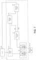
- FIG. 7 is a block diagram illustrating a configuration of the detection circuit 27.
- the percussion instrument 1 includes a control device 26 for controlling the respective parts of the percussion instrument 1.
- the control device 26 has a CPU 260, a flash ROM 261, a RAM 262, which are connected via a bus line 263.
- the CPU 260 is an arithmetic device controlling the respective parts connected by the bus line 263.
- the head sensor 3, the rim sensor 4, the detection circuit 27, and the sound source 11 are respectively connected to the bus line 263.
- the detection circuit 27 is a circuit for detecting the position of the lever 14 (see FIGs. 3 and 4 ).
- the sound source 11 may also be connected with the percussion instrument 1 wirelessly.
- the detection circuit 27 includes a control circuit 270 controlling light emission of the light projection element 190 of the light sensor 19. As described above, the light emitted from the light projection element 190 is reflected by the detected part 144 (the reflective surface 144a) of the lever 14 to be received by the light reception element 191. The light sensor 19 outputs the output value in accordance with the light amount of the light received by the light reception element 191 to a conversion circuit 271.
- the control circuit 270 causes the light projection element 190 of the light sensor 19 to blink at a predetermined interval (e.g., being turned on at an interval of 0.4 milliseconds), and, in the case where the light of the light projection element 190 is turned off, connects the conversion circuit 271 to a holding circuit 272.
- the conversion circuit 271 converts the current value (output value) output from the light reception element 191 into a voltage value, and outputs the voltage value to the holding circuit 272.
- the output value output by the light reception element 191 during the time when the light projection element 190 is turned off (referred to as "output value during the time when the light is turned off') is a value indicating the light amount of ambient light.
- the control circuit 270 cuts off the connection between the conversion circuit 271 and the holding circuit 272 in the case where the light projection element 190 is turned on.
- the conversion circuit 271 converts the current value (output value) output from the light reception element 191 during the time when the light projection element 190 is turned on, and outputs the voltage value to an arithmetic circuit 273.
- the output value output by the light reception element 191 when the light projection element 190 is turned on (referred to as "output value during the time when the light is turned on") is a value indicating the total of the ambient light and the reflected light from the detected part 144.
- the arithmetic circuit 273 subtracts the output value during the time when the light is turned off as held by the holding circuit 272 from the output value during the time when the light is turned on, and outputs a subtracted corrected value to the CPU 260 as a value indicating the position of the lever 14. Accordingly, the output value corresponding to the increase due to the ambient light can be subtracted from the output value of the light sensor 19. Therefore, the position of the lever 14 can be suppressed from being erroneously detected due to the influence of the ambient light (the position of the lever 14 can be accurately detected).
- the detected part 144 (the reflective surface 144a) is gradually exposed to the outside of the bracket 15 (see FIGs. 3 and 4 ). Therefore, the light amount of the ambient light received by the light reception element 191 may increase more easily at the time of the OFF state than the time when the lever 14 is in the ON state. That is, the light amount of the ambient light changes in accordance with the position of the lever 14.
- the light projection element 190 blinks at a very high speed (being turned on at an interval of 0.4 milliseconds), and, in the case where the light projection element 190 is turned on, the output value of the light projection element 190 at the time of being turned off immediately before being turned on (at the time of being turned off at the previous time) is held in the holding circuit 272.
- the output value of the light projection element 190 at the time of being turned off immediately before being turned on is substantially consistent with the light amount of the ambient light actually received by the light reception element 191 when the light projection element 190 is turned on.
- the output value of the light sensor 19 can be corrected accurately (the increase of the output value due to the ambient light can be accurately subtracted). Accordingly, the erroneous detection of the position of the lever 14 due to the influence of the ambient light can be suppressed (the position of the lever 14 can be accurately removed).
- control circuit 270 since the control circuit 270 turns on the light projection element 190 for a time (e.g., 0.1 milliseconds) shorter than the time (e.g., 0.3 milliseconds) during which the light projection element 190 is turned off, the power consumption of the light sensor 19 can be reduced, and the service time of the light sensor 19 (the light projection element 190) can be increased.
- the flash ROM 261 of the control device 26 is a rewritable non-volatile storage device storing programs executed by the CPU 260, fixed value data, etc.
- the flash ROM 261 stores a control program 261a executed by the CPU 260.
- the RAM 262 is a memory for rewritably storing various work data, flags, etc., when the control program 261a is executed.
- control for generating musical sounds is exerted according to an initialization process and a periodic process (see FIGs. 7 , 8A, and 8B ) to be described afterwards.
- the percussion instrument 1 outputs a sound generation instruction from the CPU 260 to the sound source 11 in accordance with the detection results of the head sensor 3, the rim sensor 4, and the detection circuit 27 (information for controlling the musical sound generated by the sound source 11 in accordance with the position of the lever 14 detected by the light sensor 19).
- the sound source 11 is a device that controls the tone of the musical sound (percussion sound) or various effects according to the sound generation instruction from the CPU 260.
- the sound source 11 is built with a DSP 110 performing an arithmetic process such as applying a filter on the waveform data or an effect.
- the amplifier 12 is connected with the sound source 11, and the speaker 13 is connected with the amplifier 12.
- the musical sound signal processed by the sound source 11 is amplified by the amplifier 12, and the musical sound is emitted from the speaker 13 based on the amplified musical sound signal.
- the RAM 262 is provided with a lever position memory 262a, a lever state flag 262b, a mask process flag 262c, and a mask time counter 262d.
- the position of the lever 14 detected by the detection circuit 27 (the corrected value of the output value of the light sensor 19) is stored over time.
- the positions of the lever 14 for the previous 5 milliseconds are stored, for example, and the operation velocity of the lever 14 is calculated from the positions of the lever 14 stored over time.
- the lever state flag 262b is a flag indicating whether the lever 14 is in the ON state or the OFF state
- the mask process flag 262c is a flag indicating whether a mask process is in progress.
- the mask process is a process for preventing an erroneous musical sound from being generated due to the vibration when the lever 14 is operated.
- the vibration during the time when the lever 14 is operated to the ON state or the OFF state (the terminal position of the movable range)
- the vibration during the operation of the lever 14 (the time when the lever 14 is rotated in the middle of the movable range) is transmitted to the shell 2.
- a musical sound (referred to "percussion sound of the rim 7") like the sound when the rim 7 is percussed is generated. That is, the percussion sound of the rim 7 is generated erroneously regardless of whether the lever 14 is operated.
- the mask process starts in the case where the lever 14 is operated, and, during a predetermined time when the mask process is executed, among the percussion sounds of the rim 7 generated based on the detection result by using the rim sensor 4, the sound generation of the percussion sound of the rim 7 generated when the output value of the rim sensor 4 is relative small (the volume is relatively small) is canceled. Accordingly, the percussion sound of the rim 7 due to the vibration when the lever 14 is operated can be suppressed from being generated.
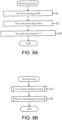
- FIG. 8A is a flowchart illustrating an initialization process
- FIG. 8B is a flowchart illustrating a periodic process.
- the initialization process shown in FIG. 8A is executed immediately after the power of the percussion instrument 1 is turned on.
- the intermediate region in the movable range of the lever 14 is divided into multiple regions, and different musical sounds are generated in the respective regions.
- a configuration as follows is exemplified: the intermediate region in the movable range of the lever 14 is split into two, i.e., a first region near the ON side and a second region near the OFF side, and different musical sounds (musical sounds applied with different effects) are generated when the head 6 is percussed in the state in which the lever 14 is located at the first region and in the state in which the lever 14 is located at the second region.
- a greater variety of musical sounds can be generated.
- the intermediate region in the movable range of the lever 14 is split into three or more (if three or more types of musical sounds are generated in the intermediate region), a greater variety of musical sounds can be generated.
- the light sensor 19 is exemplified as an example of the sensor (first sensor) that detects the position of the lever 14.
- the position of the lever 14 may also be detected by using other conventional sensors (e.g., a sensor, a potentiometer, etc., that detects a magnetic field change or an electrostatic capacity change)
- the configuration in which the reflective surface 144a is rotated (displaced) in a direction substantially orthogonal to the direction of the optical axis of the light sensor 19 (the light projection element 190) is described.
- the reflective surface of the lever 14 may also be displaced in the direction of the optical axis of the light sensor 19. That is, the position of the light sensor 19 can be set as appropriate as long as the configuration is a configuration that can detect the position of the lever 14.
- the reflective surface 144a is displaced in a direction substantially orthogonal to the optical axis of the light sensor 19
- the lever 14 is rotated so that the angle of the reflective surface 144a is constantly 20° or less (or 10° or less) with respect to the optical axis of the light sensor 19 in the state in which the light of the light sensor 19 is emitted to the reflective surface 144a (the reflective surface 144a is located on the optical axis of the light sensor 19).
- the rotation shaft 16 of the lever 14 (the rotation center of the lever 14) and the optical axis of the light sensor 19 are substantially orthogonal to each other” may indicate that the rotation center of the lever 14 is located on the optical axis of the light sensor 19.
- the rotation center of the lever may not be necessarily located on the optical axis of the light sensor 19, as long as the configuration is a configuration in which the lever 14 is rotated so that the angle of the reflective surface 144a is constantly 20° or less (more preferably 10° or less) with respect to the optical axis of the light sensor 19, as described above.
- the reflective material 24 installed to the reflective surface 144a of the lever 14 is formed by a resin layer and a metal layer, the resin layer being formed by using a film made of resin (e.g., PET), and the metal layer being formed by metal (e.g., aluminum) laminated on the resin layer.
- a film made of resin e.g., PET
- metal layer being formed by metal (e.g., aluminum) laminated on the resin layer.
- the disclosure is not limited thereto.
- other conventional films may also be used as the reflective material 24, or the reflective material 24 may be omitted, as long as the light reflected by the reflective surface 144a can be adjusted.
- the position of the lever 14 is detected by causing the light sensor 19 to blink and subtracting the output value during the time when the light is turned off as held by the holding circuit 272 from the output value during the time when the light is turned on by using the detection circuit 27 (the control circuit 270) is described.
- the process for detecting the position of the lever 14 may also be performed on the CPU 260, instead of the detection circuit 27.
- it may also be configured that the light sensor 19 is caused to blink continuously, and such subtraction is not performed.
- the case where the light projection element 190 is turned on for a time period shorter than the time during which the light projection element 190 is turned off is not limited thereto.
- the time during which the light projection element 190 is turned off and the time during which the light projection element 190 is turned on may be the same, or the time during which the light projection element 190 is turned on may be longer than the time during which the light projection element 190 is turned off.
- the disclosure is not limited thereto.
- the percussion instrument 1 may also include the sound source 11.
- the information controlling the musical sound is generated in accordance with the position of the lever 14 detected by the light sensor 19, and, by generating the musical sound signal by using the sound source 11 based on such information, a variety of musical sounds can be generated.
Landscapes
- Physics & Mathematics (AREA)
- Engineering & Computer Science (AREA)
- Acoustics & Sound (AREA)
- Multimedia (AREA)
- Electrophonic Musical Instruments (AREA)
Abstract
Description
- The disclosure relates to a percussion instrument and a musical sound generation method, and particularly relates to a percussion instrument and a musical sound generation method capable of generating various musical sounds.
- For example,
Patent Document 1 discloses a percussion instrument able to bring a snare wire 29 into contact with or separate the snare wire 29 from the lower surface of aresonance head 22 through an operation that rotates a lever 34. In such percussion instrument, by using a sensor 48 provided on the lower surface of theresonance head 22, whether the snare wire 29 contacts theresonance head 22 is detected. In the case where abatter head 21 is percussed, different musical sounds are generated when theresonance head 22 and the snare wire 29 are in contact and when theresonance head 22 and the snare wire 29 are separated. Accordingly, various musical sounds can be generated. - [Patent Document 1]
Japanese Laid-open No. 2017-194585 FIGs. 1 ,2 ). - However, in the conventional technique, it is only possible to generate two types of musical sounds when the
resonance head 22 and the snare wire 29 are in contact (the state where the lever 34 is ON) and when theresonance head 22 and the snare wire 29 are separated (the state where the lever 34 is OFF). Therefore, it is still insufficient from the point of generating various musical sounds. - The disclosure has been made in view of the above issue, and an objective of the disclosure is to provide a percussion instrument and a musical sound generation method capable of generating various musical sounds.
- In order to achieve the objective, an aspect of the disclosure provides a percussion instrument. The percussion instrument includes: a percussed object, percussed by a player; an operator, rotatable and provided to adjust a musical sound generated at a time when the percussed object is percussed; and a first sensor, detecting a position of the operator between an initial position and a terminal position of a rotation operation of the operator. The percussion instrument is able to generate information for controlling the musical sound in accordance with the position of the operator detected by the first sensor.
- Another aspect of the disclosure provides a musical sound generation method. The musical sound generation method is provided for a percussion instrument including: a percussed object, percussed by a player; an operator, rotatable and provided to adjust a musical sound generated at a time when the percussed object is percussed; and a first sensor, detecting a position of the operator between an initial position and a terminal position of a rotation operation of the operator. The musical sound generation method includes: generating the musical sound based on the position of the operator detected by the first sensor.
-
-
FIG. 1 is an exploded perspective view illustrating a percussion instrument according to an embodiment. -
FIG. 2 is a perspective view illustrating a state in which a lever is removed from a bracket. -
FIG. 3 is a partially enlarged cross-sectional view illustrating the percussion instrument. -
FIG. 4 is a partially enlarged cross-sectional view illustrating the percussion instrument in a state in which the lever is rotated from the state ofFIG. 3 . -
FIG. 5 is a partially enlarged cross-sectional view of the percussion instrument taken along a line V-V ofFIG. 3 . -
FIG. 6 is a block diagram illustrating an electrical configuration of the percussion instrument. -
FIG. 7 is a block diagram illustrating a configuration of a detection circuit. -
FIG. 8A is a flowchart illustrating an initialization process, andFIG. 8B is a flowchart illustrating a periodic process. -
FIG. 9 is a flowchart illustrating a lever position detection process. -
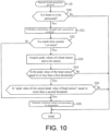
FIG. 10 is a flowchart illustrating a musical sound generation process. - In the following, the exemplary embodiment are described with reference to the drawings. Firstly, referring to
FIGs. 1 and2 , the overall configuration of apercussion instrument 1 is described.FIG. 1 is an exploded perspective view illustrating apercussion instrument 1 according to an embodiment.FIG. 2 is a perspective view illustrating a state in which alever 14 is removed from abracket 15. - As shown in
FIG. 1 , thepercussion instrument 1 is an electronic percussion instrument simulating an acoustic drum, and includes ashell 2 forming the housing thereof. Theshell 2 is formed in a cylindrical shape by using metal, wood, or resin. In the following description, the direction around the axis of theshell 2 is described as a circumferential direction, and the direction orthogonal to the axis of theshell 2 is described as a radial direction. Aframe 5 supporting ahead sensor 3 and a rim sensor 4 (seeFIG. 6 for the rim sensor 4) is hooked to the upper edge portion of theshell 2. - The
frame 5 includes abottom part 50, asidewall part 51, acurved part 52. Thebottom part 50 is in a substantially disc shape. Thesidewall part 51 stands upward from the outer edge of thebottom part 50. Thecurved part 51 is formed on the upper edge of thesidewall part 51. Therespective parts 50 to 52 are integrally formed by using a resin material. - The
sidewall part 51 of theframe 5 is formed in a cylindrical shape surrounding the entire periphery of thebottom part 50, and thecurved part 52 is curved from the upper edge of thesidewall part 51 toward the outer peripheral side. Thecurved part 52 is formed in an arc shape (convex upward) along the upper edge of theshell 2. With thecurved part 52 being hooked to the upper edge of theshell 2, theframe 5 is supported by the inner peripheral side of theshell 2. - An opening portion of the frame 5 (shell 2) on the upper end side is covered by a
head 6. Thehead 6 is formed in a disk shape by using a mesh woven by synthetic fibers, and ahead frame 60 in an annular shape is fixed to the outer edge of thehead 6. Thehead frame 60 is formed by using a resin material, and thehead 6 and thehead frame 60 are integrally formed through die-molding. Nevertheless, thehead frame 60 may also be formed by using a material (e.g., metal such as aluminum or iron) other than resin, and thehead frame 60 may also be bonded to thehead 6 through adhesion etc. - The
head 6 is fixed to the percussion instrument 1 (shell 2) by using arim 7 in an annular shape. In therim 7, through holes (not shown) for insertion oftension bolts 8 are formed at equal interval in the circumferential direction. On the outer peripheral side of the shell 2 (housing), multiple lugs 9 (at eight positions in the embodiment) for fastening thetension bolts 8 are provided at equal intervals in the circumferential direction. - In the
lug 9, ascrew hole 90 is formed. In the state in which thehead frame 60 of thehead 6 is hooked to therim 7, thetension bolt 8 is fastened to thescrew hole 90 of thelug 9, thereby applying a tensile force to thehead 6. Accordingly, the upper surface of thehead 6 serves as a percussion surface, and the vibration of the percussion to the percussion surface is detected by thehead sensor 3. - The
head sensor 3 is formed by onecentral sensor 3a supported by the center of thebottom part 50 of theframe 5 and multiple (three in the embodiment)peripheral sensors 3b arranged at equal interval in the circumferential direction on the outer peripheral side with respect to thecentral sensor 3a. Therespective sensors plate 10 fixed to abottom part 50 of theframe 5. - A disc-shaped sensor (piezoelectric element that is not shown) is bonded to the upper surface of the
plate 10 via a cushion (not shown) to which a double-sided tape is attached to the front and back, and the cushion is bonded to the upper surface of the sensor. Thecentral sensor 3a and theperipheral sensors 3b are formed by the cushions and sensors. The cushions bonded to the upper surfaces of thecentral sensor 3a and theperipheral sensors 3b are cushion materials in a truncated conical shape formed by using a flexible material, such as sponge, rubber, thermoplastic elastomer, etc., and contact the lower surface of thehead 6. - While not shown in the drawings, the rim sensor 4 (see
FIG. 6 ) for detecting the percussion to therim 7 is bonded to the lower surface of theplate 10 supporting thecentral sensor 3a. Therim sensor 4 is a disc-shaped piezoelectric element. When vibrations are detected by thehead sensor 3 and therim sensor 4, a musical sound signal is generated by a sound source 11 (seeFIG. 6 ) based on such detection result, and the musical sound signal is output to anamplifier 12 and a speaker 13 (seeFIG. 6 ). Accordingly, an electronic musical sound is emitted from thespeaker 13. In thepercussion instrument 1, alever 14 for controlling the tone or the volume of the electronic musical sound is provided. Thelever 14 is rotatably installed to the outer peripheral surface of theshell 2 by using thebracket 15. - As shown in
FIG. 2 , thebracket 15 includes an outerperipheral wall 150 forming the outer peripheral surface thereof, and a pair ofsidewalls 151 extend toward the inner peripheral side (the side of the shell 2) from the two ends of the outerperipheral wall 150 in the circumferential direction. The upper ends of the pair ofsidewalls 151 are connected in the circumferential direction by anupper wall 152, and the lower ends are connected in the circumferential direction by alower wall 153. Therespective walls 150 to 153 of thebracket 15 are integrally formed by using metal. - A
cavity 154 surrounded by therespective walls 150 to 153 is provided inside thebracket 15. Anopening 155 connecting thecavity 154 and the outside is formed in thebracket 15. Theopening 155 is formed so that the outerperipheral wall 150 and thelower wall 153 of thebracket 15 are cut out continuously. Aninsertion hole 156 penetrating through the sidewall 151 (outer peripheral wall 150) is formed on the lower end side of theopening 155. - A pair of
insertion holes 156 are formed to sandwich theopening 155 and face each other. A cylindricallycolumnar rotation shaft 16 is inserted into each of the pair of insertion holes 156. Thelever 144 is pivotally supported by therotation shaft 16. - The
lever 14 includes anoperation part 140 extending in the upper-lower direction and a supportedpart 141 protruding from the inner peripheral surface of the lower end side of theoperation part 140 toward the inner peripheral side. In addition, thelever 14 is formed in a substantially L shape. Shaft holes 142 are formed on the side surfaces of the two sides of the supportedpart 141 toward the circumferential direction. - At the time of assembling the
lever 14 to thebracket 15, the supportedpart 141 is inserted toward thecavity 154 inside thebracket 15 from theopening 155. In the inserted state, therotation shaft 16 passing through theinsertion hole 156 is fit with theshaft hole 142 of thelever 14. Then, by fixing therotation shaft 16 fit into theshaft hole 142 to the bracket 15 (insertion hole 156) by using a worm screw not shown herein, thelever 14 is rotatably supported by thebracket 15. - In the following, with reference to
FIGs. 2 to 4 , the configuration for rotating thelever 14 is described in detail.FIG. 3 is a partially enlarged cross-sectional view illustrating thepercussion instrument 1.FIG. 4 is a partially enlarged cross-sectional view illustrating thepercussion instrument 1 in a state in which thelever 14 is rotated from the state ofFIG. 3. FIGs. 3 and4 illustrate a cross-section cut at a plane including a light sensor (the optical axis of the light emitted by a light projection element 190), which is a plane orthogonal to the axial direction of therotation shaft 16. In addition,FIGs. 3 and4 illustrate therotation shaft 16 hidden by thelever 14 by using a broken line. In addition, a portion of the internal configuration of the bracket 15 (e.g., asupport wall 159 shown inFIG. 5 ) is omitted to provide schematic illustration. - As shown in
FIGs. 2 and3 , in the state in which thelever 14 is pivotally supported by therotation shaft 16, the supportedpart 141 of thelever 1 4 protrudes toward thecavity 154 of thebracket 15 from therotation shaft 16. In the supportedpart 141, aninsertion hole 143 having an opening is formed at the tip end thereof (the end part on the inner peripheral side). Apin 17 of a plunger is inserted into theinsertion hole 143. - The
pin 17 includes acylindrical part 170 having a cylindrical shape and inserted into theinsertion hole 143 and a blockingpart 171 having a substantially semi-spherical shape and blocking an end side (the right side ofFIG. 3 ) of thecylindrical part 170. Thecylindrical part 170 and the blockingpart 171 are integrally formed. - A
coil spring 18 is inserted into the inner peripheral side of thecylindrical part 170. Thecoil spring 18 applies an elastic force in a direction protruding from the insertion hole 143 (a direction orthogonal to the axial direction of the rotation shaft 16) to thepin 17. With the elastic force, the blockingpart 171 at the tip end portion of thepin 17 is pressed against a slidingwall 157 of thebracket 15. The slidingwall 157 is formed with a firstconcave surface 157a, aconvex surface 157b connected with the upper edge of the firstconcave surface 157a, and a secondconcave surface 157c connected with the upper edge of theconvex surface 157b. - When viewed in the cross-section cut at the plane orthogonal to the axial direction of the
rotation shaft 16, the firstconcave surface 157a and the secondconcave surface 157c are formed in a curved shape recessed in a direction away from therotation shaft 16. In addition, when viewing the same cross-section, theconvex surface 157b is formed in a curved shape convex toward the side of therotation shaft 16. The concave andconvex surfaces 157a to 157c are smoothly continuous from the lower end side to the upper end side of the slidingwall 157. In the state in which the blockingpart 171 of thepin 17 is pressed against the firstconcave surface 157a, theoperation part 140 of thelever 14 forms a posture extending in the upper-lower direction (vertical direction). - As shown in
FIGs. 3 and4 , with thelever 14 being rotated about therotation shaft 16 so as to push down theoperation part 140 from the state in which the blockingpart 171 of thepin 17 is pressed against the firstconcave surface 157a, the blockingpart 171 of thepin 17 slides on theconvex surface 157b. At this time, thepin 17 slides in a direction that compresses thecoil spring 18 inside theinsertion hole 143 of the supportedpart 141. Therefore, it is possible to feel a response when pushing down thelever 14. - When the
lever 14 is rotated until the blockingpart 171 gets over the top of theconvex surface 157b, thepin 17 stretches from theinsertion hole 143 due to the elastic force of thecoil spring 18, and the blockingpart 171 is pressed against the secondconcave surface 157c. In the state in which the blockingpart 171 is pressed against the secondconcave surface 157c, theoperation part 140 of thelever 14 forms a posture inclined with respect to the vertical direction. In the case of being rotated about therotation shaft 16 to raise theinclined lever 14, through an operation opposite to the case of pushing down thelever 14, the blockingpart 171 slides along the slidingwall 157 to be pressed against the firstconcave surface 157a. - In this way, the
lever 14 is configured to be rotatable between the position of raising the operation part 140 (the state ofFIG. 3 ) and the position of pushing down the operation part 140 (the state ofFIG. 4 ). In thepercussion instrument 1 of the embodiment, although a snare wire such as an acoustic snare drum is not installed, an operation at the time when the snare wire is brought into contact with a resonance head (a head installed to the opening portion of the shell on a side opposite to thehead 6 shown inFIG. 1 ) can be simulated through rotation to raise thelever 14 in the state of being pushed down. Meanwhile, by performing an opposite operation, an operation at the time of removing the snare wire from the resonance head can be simulated. - In the following description, the state in which the
lever 14 is raised (the state ofFIG. 3 in which the blockingpart 171 is pressed against the firstconcave surface 157a) is defined as the state in which thelever 14 is ON, and the state in which thelever 14 is pushed down (the state ofFIG. 4 in which the blockingpart 171 is pressed against the secondconcave surface 157c) is defined as the state in which thelever 14 is OFF. - The position of the lever 14 (the rotation angle of the lever 14) within the movable range between ON and OFF is detected by the
light sensor 19. Asubstrate 20 is fixed to the inside of thebracket 15. Thelight sensor 19 is installed to the lower surface of thesubstrate 20. Thelight sensor 19 is formed by thelight projection element 190 emitting light downward and a light reception element 191 (seeFIG. 5 ) whose light reception part faces downward to receive the light. - The detected
part 144 protrudes toward the inner peripheral side from the inner peripheral surface of theoperation part 140, and the upper surface of the detectedpart 144 is formed as a planarreflective surface 144a. In the state in which thelever 14 is ON (the state ofFIG. 3 ), thelight sensor 19 and thereflective surface 144a face each other in the upper-lower direction. In addition, the light emitted from thelight projection element 190 of thelight sensor 19 is reflected by thereflective surface 144a and received by the light reception element 191 (seeFIG. 5 ). - As shown in
FIGs. 3 and4 , when thelever 14 rotates from the ON state to the OFF state, the amount of light reflected from thereflective surface 144a toward the light reception element 191 (light received by the light reception element 191) decreases. Meanwhile, when thelever 14 rotates from the OFF state to the ON state, the amount of light reflected from thereflective surface 144a toward thelight reception element 191 increases. Thelight sensor 19 outputs an output value in accordance with a change of the light amount of light received by thelight reception element 191, and the position of thelever 14 is detected from the output value of thelight sensor 19. During the performance using thepercussion instrument 1, thelever 14 is used to perform various operations. A performance method using thepercussion instrument 1 is described. - Firstly, the player operates a
switch 21 fixed to the upper surface of thesubstrate 20 and performs various settings in thepercussion instrument 1. The various settings refer to the setting of the output level (volume) of the musical sound signal, the setting of ON/OFF of the effect applied to a musical sound, the drum kit setting (the type of the musical sound generated), etc. An example of the drum kit setting is described in the following. - The
switch 21 includes anoperation part 210 for the player to push or turn. A throughhole 158 for theoperation part 210 to pass through penetrates through theupper wall 152 of thebracket 15. By rotating thelever 14 between the ON state and the OFF state in a state in which theoperation part 210 is operated and the mode of thepercussion instrument 1 is set to a drum kit change mode, the drum kit can be selected. - A
light emitter 22, such as an LED, is provided on the outer edge side (left side ofFIGs. 3 and4 ) of thesubstrate 20 with respect to theswitch 21, thelight emitter 22 emits light in a color in accordance with the drum kit selected by the player. In other words, thelight emitter 22 emits light in a color in accordance with the position of thelever 14. Thelight emitter 22 is fixed to the upper surface of thesubstrate 20, and alens 23 through which the light of thelight emitter 22 transmits to the outside is fixed to a corner part where the outerperipheral wall 150 of thedrum kit 15 and theupper wall 152 intersect. By visually recognizing the light of thelight emitter 22 emitted from thelens 23, the type of the selected drum kit can be determined. - After the drum kit is selected, the
operation part 210 is operated to end the various settings (e.g., the mode of thepercussion instrument 1 is set to a performance mode). In such state, in the case where thelever 14 is rotationally operated from the OFF state (the state ofFIG. 4 ) to the ON state (the state ofFIG. 3 ), the sound when the snare wire contacts the resonance head is generated. Meanwhile, in the case where thelever 14 is rotationally operated to the OFF state from the ON state, the sound when the snare wire leaves the resonance head is generated. Of course, the sound simulating a snare wire detachment sound is generated when thehead 6 or the rim 7 (seeFIG. 1 ) is not percussed. - In addition, in the embodiment, the velocity of the
lever 14 is calculated based on the change of the output value of the light sensor 19 (i.e., the position of the lever 14) over time, and a musical sound in accordance with the velocity is generated. For example, in the case where thelever 14 is operated from the OFF state to the ON state at a relatively high velocity, the contact sound between the resonance head and the snare wire is generated at a relatively high volume. Meanwhile, in the case where thelever 14 is operated from the OFF state to the ON state at a relatively low velocity, such contact sound is generated at a relatively low volume. In this way, by generating the contact/detachment sound of the snare wire when thelever 14 is operated, the acoustic snare drum can be simulated by using thepercussion instrument 1. - In addition, in the case where the
head 6 or the rim 7 (seeFIG. 1 ) is percussed in the state where thelever 14 is ON, a percussion sound (electronic musical sound) at the time when the snare wire contacts the resonance head is generated. Meanwhile, in the case where thehead 6 is percussed in the state where thelever 14 is OFF, a percussion sound when the snare wire leaves the resonance head is generated. - Moreover, in the embodiment, in the case where the
head 6 is percussed at the time when thelever 14 is located between the ON state and the OFF state, a musical sound of a further different tone is generated. Examples of the musical sound of a further different tone include a musical sound in which an effect (sound effect), such as reverb, delay, vibrato, etc., is applied with respect to the musical sound generated at the time of the percussion to thehead 6, a musical sound whose tone or volume different from the musical sound generated at the time of the percussion to thehead 6, etc. In addition, musical sounds to which different effects are applied are generated in the case where thehead 6 is percussed while thelever 14 is operated at a relatively high velocity and the case where the head is percussed while thelever 14 is operated at a relatively low velocity. - As described above, in the embodiment, the
light sensor 19 that detects the position of the lever 14 (an intermediate position between the initial position and the terminal position of the lever 14) between the ON state and the OFF state of thelever 14 is provided, and a musical sound in accordance with the position of thelever 14 detected by suchlight sensor 19 is generated. That is, in each of the ON state of thelever 14, the OFF state of thelever 14, and the state where thelever 14 is therebetween, different musical sounds are generated when thehead 6 is percussed. Therefore, compared with the conventional technique where musical sounds can only be generated based on the states where thelever 14 is ON and OFF, musical sounds of a greater variety can be generated. In addition, since the velocity of thelever 14 can also be detected from the change of the position of thelever 14 over time, different musical sounds are generated in accordance with the velocity. Thus, it is possible to generate a greater variety of musical sounds. - Here, while the position of the
lever 14 can be detected by using a magnetic sensor, in the case of such configuration, other metal components (magnetic bodies) in the surroundings may interfere with the magnetism of the magnetic sensor. - Comparatively, in the embodiment, by using the
light sensor 19 including thelight projection element 190 emitting light toward thereflective surface 144a of thelever 14 and thelight reception element 191 receiving the light reflected from thereflective surface 144a, the position of thelever 14 is detected. According to such configuration, differing from the case of using a magnetic sensor, other metal components (magnetic bodies) in the surroundings can be suppressed from affecting the position detection of thelever 14 using thelight sensor 19. Accordingly, the position of thelever 14 can be accurately detected. - As another method for detecting the position of the
lever 14 by using thelight sensor 19, it is possible to adopt a configuration in which the reflective surface of thelever 14 is displaced in the direction of the optical axis of the light sensor 19 (light projection element 190). As such configuration, examples include a configuration in which the tip end surface (the surface facing the right side inFIG. 3 ) of the detectedpart 144 is set as a reflective surface, and thelight sensor 19 is disposed in a posture where light is emitted in a direction (the left side ofFIG. 3 ) substantially orthogonal to the reflective surface. In the case of such configuration, it suffices as long as the width dimension of the reflective surface in the upper-lower direction (the thickness of the detected part 144) is large enough to be able to reflect the light from thelight sensor 19. - However, if the reflective surface of the
lever 14 is configured to be displaced in the direction of the optical axis of thelight sensor 19, when the detected part 144 (reflective surface) is rotated in a direction away from thelight sensor 19, the output value of thelight sensor 19 may decrease drastically. Accordingly, the detectable range of the position of thelever 14 may be reduced easily. - Comparatively, in the embodiment, in the state where the
lever 14 is ON (the state ofFIG. 3 ), thereflective surface 144a of the detectedpart 144 is orthogonal to the optical axis of thelight sensor 19, and, in the case where thelever 14 is rotated toward the OFF state from such state, thereflective surface 144a is displaced (rotated) in a direction substantially orthogonal to the direction of the optical axis of the light sensor 19 (the light projection element 190). By displacing thereflective surface 144a in this way, in the case where thelever 14 is rotated from ON to the OFF state, the area of thereflective surface 144a reflecting the light of the light sensor 19 (referred to as "reflective region of thereflective surface 144a" in the following) gradually decreases. In the case where thelever 14 is rotated in an opposite direction, the reflective region of thereflective surface 144a can increase gradually. - In this way, by increasing/decreasing the reflective region of the
reflective surface 144a together with the rotation of thelever 14, compared with the case where the reflective surface is displaced in the direction of the optical axis of thelight sensor 19 as described above, the output value of thelight sensor 19 hardly increases/decreases drastically. Accordingly, the detection range of the position of thelever 14 is widened, and the position of thelever 14 can be accurately detected. - In addition, in the embodiment, the axis of the rotation shaft 16 (the rotation center of the lever 14) is orthogonal to the optical axis of the light sensor 19 (the
rotation shaft 16 is located on an extension line of the optical axis of the light sensor 19). Accordingly, compared with the configuration in which the axis of therotation shaft 16 and the optical axis of thelight sensor 19 are not orthogonal to each other (e.g., theoptical sensor 19 is disposed on the left side with respect to the position shown inFIG. 3 ), the position of thelever 14 and the reflective region of thereflective surface 144a (the output value of the light sensor 19) may easily increase/decrease proportionally. Accordingly, the position of thelever 14 can be further accurately detected. - In addition, a
reflective material 24 is installed to thereflective surface 144a of the detectedpart 144. While not shown in the drawings, thereflective material 24 is formed by a resin layer formed by using a film made of resin (e.g., PET) and a metal layer manufactured by using metal (e.g., aluminum) laminated on the resin layer. The metal layer is formed by laminating a metal foil on the resin layer or coating metal on the resin layer by using vapor evaporation, etc. The metal layer is laminated between thereflective surface 144a and the resin layer and the upper surface of the metal layer is covered by the resin layer. Therefore, the metal layer can be suppressed from being damaged. - By installing the
reflective material 24 to thereflective surface 144a, the amount of light reflected from thereflective surface 144a (reflective material 24) toward thelight reception element 191 can be adjusted. Accordingly, thelight reception element 191 can receive an appropriate light amount of light. Therefore, the increase/decrease of the reflective region of thereflective surface 144a together with the rotation of thelever 14 can be accurately detected by thelight reception element 191. Accordingly, the position of thelever 14 can be accurately detected. - In this way, in the embodiment, the position of the
lever 14 is detected based on the light amount of light received by thelight reception element 191 of thelight sensor 19. Therefore, when thelight reception element 191 receives ambient light, the position of thelever 14 cannot be accurately detected. As such ambient light, examples include light that is turned on in pulses (blinking rapidly) at a predetermined frequency, such as LED lighting, and light that is emitted continuously without blinking, such as sunlight and light bulbs. - Comparatively, in the embodiment, while details will be described subsequently, it is configured that the
light projection element 190 of thelight sensor 19 blinks at a high speed (e.g., being turned on at an interval of 0.4 milliseconds) by using a detection circuit 27 (seeFIG. 7 ). Accordingly, whether the light received by thelight reception element 191 is the light of thelight projection element 190 or the ambient light that emits light continuously, such as sunlight, can be distinguished. - Meanwhile, although the ambient light, such as LED lighting, blinks at a high speed, like the
light projection element 190, the LED lighting emits light in a wavelength region of visible light. Comparatively, thelight projection element 190 of the embodiment adopts an element that emits light at a wavelength out of the visible light region (near infrared light). Accordingly, whether the light received by thelight reception element 191 is the light of thelight projection element 190 or the ambient light such as LED lighting can be distinguished. - In this way, with the
light projection element 190 blinking at a high speed or emitting light at a wavelength outside the visible light region, the ambient light and the light of thelight projection element 190 can be distinguished. Nevertheless, to detect the position of thelever 14 with higher accuracy, it may be that thelight reception element 191 is not irradiated with ambient light as much as possible. Regarding alight shielding member 25 for shielding the ambient light, while the description is made mainly with reference toFIGs. 3 and5 ,FIG. 2 may also be taken into consideration as appropriate while the description is made.FIG. 5 is a partially enlarged cross-sectional view of thepercussion instrument 1 taken along a line V-V ofFIG. 3 . - As shown in
FIGs. 3 and5 , in the light reception element 191 (seeFIG. 5 ) of thelight sensor 19, the light reception part thereof faces toward the lower surface side of thesubstrate 20. Accordingly, the light from lighting, etc., provided on the ceiling side is shielded by thesubstrate 20 or theupper wall 152 of thebracket 15. Therefore, such ambient light can be suppressed from being erroneously detected by thelight reception element 191. - Meanwhile, the
opening 155 for insertion of the supportedpart 141 of thelever 14 is formed on the side of the lower wall 153 (seeFIG. 3 ) of thebracket 15, and thelever 14 is pivotally supported by therotation shaft 16 provided at theopening 155. A spacing is defined between the supportedpart 141 and theopening 155 in the periphery of the rotation shaft 16 (the movable portion of the lever 14). Therefore, light reflected from the floor etc., may enter through the spacing. The ambient light from the floor side is shielded by thelight shielding member 25. - The
light shielding member 25 includes alower wall part 250 for covering the detectedpart 144 of thelever 14 from the lower side, andsidewall parts 251 stand upward from the two ends of thelower wall part 250 in the circumferential direction. Aninner wall part 252 stands upward from the end of thelower wall part 250 on the inner peripheral side (the right side ofFIG. 3 ), and theinner wall part 252 connects the pair ofsidewall parts 251. - A pair of overhanging parts 253 (see
FIG. 5 ) overhang on the two sides in the circumferential direction from the side surfaces of the pair ofsidewall parts 251 on the upper end side, and aclaw part 254 in a substantially L shape (seeFIG. 2 for the point that theclaw part 254 is formed in an L shape) is formed at the lower end of each of the pair ofsidewall parts 251. Therespective wall parts 250 to 254 of thelight shielding member 25 are integrally formed by using an elastic body, such as rubber or elastomer. Thelight shielding member 25 is installed to the support wall 159 (seeFIG. 5 ) of the bracket by using theoverhang parts 253 and theclaw parts 254. - The
support wall 159 is an L-shaped wall protruding from the inner surface of thesidewall 151 of thebracket 15. Thesupport wall 159 is formed on each of the pair ofsidewalls 151. By hooking theoverhang parts 253 and theclaw parts 254 of thelight shielding member 25 to the pair ofsupport walls 159, thelight shielding member 25 is installed to the inside of thebracket 15. - As shown in
FIG. 3 , when viewed in the axial direction of therotation shaft 16, thelower wall part 250 of thelight shielding member 25 is disposed between thelight sensor 19 and therotation shaft 16. As shown inFIG. 5 , in the state in which thelever 14 is ON (the state in which the light of thelight sensor 19 is emitted onto thereflective surface 144a), thereflective surface 144a of thelever 14 is located between the light sensor 19 (the light reception element 191) and the light shielding member 25 (the lower wall part 250). Accordingly, even in the case where the spacing between the supportedpart 141 of thelever 14 and theopening 155 of thebracket 15 is formed on the periphery of therotation shaft 16, the ambient light that enters from the spacing can be shielded by thelower wall part 250 of thelight shielding member 25. Accordingly, thelight reception element 191 can be suppressed from receiving the ambient light, so the position of thelever 14 can be accurately detected. - In addition, in the state where the
lever 14 is ON, thesidewall parts 251 and the inner wall part 252 (seeFIG. 3 ) of thelight shielding member 25 protrude upward (the side of the light sensor 19) from thereflective surface 144a , and thereflective surface 144a is surrounded by therespective wall parts bracket 15, the ambient light emitted to thereflective surface 144a can be shielded by therespective wall parts light reception element 191 can be suppressed from receiving the ambient light, so the position of thelever 14 can be accurately detected. - In this way, the ambient light emitted from the lower side of the
bracket 15 can be substantially shielded by thelight shielding member 25. In addition, the ambient light from the upper side of thebracket 15 is also substantially shielded by thesubstrate 20 or theupper wall 152 of thebracket 15. Meanwhile, it is difficult to completely shield the ambient light traveling to thelight reception element 191, such as the external light reflected off thelever 14 and entering thebracket 15 or the external light directly entering the bracket 15 (e.g., through the opening 155), etc. - Comparatively, the embodiment is configured to be able to suppress the position of the
lever 14 from being erroneously detected due to the ambient light received by thelight reception element 191. Regarding the configuration, description is made with reference toFIGs. 6 and7 .FIG. 6 is a block diagram illustrating an electrical configuration of thepercussion instrument 1.FIG. 7 is a block diagram illustrating a configuration of thedetection circuit 27. - As shown in
FIG. 6 , thepercussion instrument 1 includes a control device 26 for controlling the respective parts of thepercussion instrument 1. The control device 26 has aCPU 260, aflash ROM 261, aRAM 262, which are connected via abus line 263. TheCPU 260 is an arithmetic device controlling the respective parts connected by thebus line 263. Thehead sensor 3, therim sensor 4, thedetection circuit 27, and thesound source 11 are respectively connected to thebus line 263. Thedetection circuit 27 is a circuit for detecting the position of the lever 14 (seeFIGs. 3 and4 ). Thesound source 11 may also be connected with thepercussion instrument 1 wirelessly. - As shown in
FIG. 7 , thedetection circuit 27 includes acontrol circuit 270 controlling light emission of thelight projection element 190 of thelight sensor 19. As described above, the light emitted from thelight projection element 190 is reflected by the detected part 144 (thereflective surface 144a) of thelever 14 to be received by thelight reception element 191. Thelight sensor 19 outputs the output value in accordance with the light amount of the light received by thelight reception element 191 to aconversion circuit 271. - The
control circuit 270 causes thelight projection element 190 of thelight sensor 19 to blink at a predetermined interval (e.g., being turned on at an interval of 0.4 milliseconds), and, in the case where the light of thelight projection element 190 is turned off, connects theconversion circuit 271 to a holdingcircuit 272. When thelight projection element 190 is turned off, theconversion circuit 271 converts the current value (output value) output from thelight reception element 191 into a voltage value, and outputs the voltage value to the holdingcircuit 272. The output value output by thelight reception element 191 during the time when thelight projection element 190 is turned off (referred to as "output value during the time when the light is turned off') is a value indicating the light amount of ambient light. - Meanwhile, the
control circuit 270 cuts off the connection between theconversion circuit 271 and the holdingcircuit 272 in the case where thelight projection element 190 is turned on. Theconversion circuit 271 converts the current value (output value) output from thelight reception element 191 during the time when thelight projection element 190 is turned on, and outputs the voltage value to anarithmetic circuit 273. The output value output by thelight reception element 191 when thelight projection element 190 is turned on (referred to as "output value during the time when the light is turned on") is a value indicating the total of the ambient light and the reflected light from the detectedpart 144. - Then, the
arithmetic circuit 273 subtracts the output value during the time when the light is turned off as held by the holdingcircuit 272 from the output value during the time when the light is turned on, and outputs a subtracted corrected value to theCPU 260 as a value indicating the position of thelever 14. Accordingly, the output value corresponding to the increase due to the ambient light can be subtracted from the output value of thelight sensor 19. Therefore, the position of thelever 14 can be suppressed from being erroneously detected due to the influence of the ambient light (the position of thelever 14 can be accurately detected). - Here, as described above, at the time when the
lever 14 is rotated from the ON state to the OFF state, the detected part 144 (thereflective surface 144a) is gradually exposed to the outside of the bracket 15 (seeFIGs. 3 and4 ). Therefore, the light amount of the ambient light received by thelight reception element 191 may increase more easily at the time of the OFF state than the time when thelever 14 is in the ON state. That is, the light amount of the ambient light changes in accordance with the position of thelever 14. - Comparatively, in the embodiment, the
light projection element 190 blinks at a very high speed (being turned on at an interval of 0.4 milliseconds), and, in the case where thelight projection element 190 is turned on, the output value of thelight projection element 190 at the time of being turned off immediately before being turned on (at the time of being turned off at the previous time) is held in the holdingcircuit 272. The output value of thelight projection element 190 at the time of being turned off immediately before being turned on is substantially consistent with the light amount of the ambient light actually received by thelight reception element 191 when thelight projection element 190 is turned on. Therefore, by subtracting the output value at the time of being turned off immediately before being turned on from the output value at the time of being turned on, the output value of thelight sensor 19 can be corrected accurately (the increase of the output value due to the ambient light can be accurately subtracted). Accordingly, the erroneous detection of the position of thelever 14 due to the influence of the ambient light can be suppressed (the position of thelever 14 can be accurately removed). - In addition, since the
control circuit 270 turns on thelight projection element 190 for a time (e.g., 0.1 milliseconds) shorter than the time (e.g., 0.3 milliseconds) during which thelight projection element 190 is turned off, the power consumption of thelight sensor 19 can be reduced, and the service time of the light sensor 19 (the light projection element 190) can be increased. - Referring to
FIG. 6 again, theflash ROM 261 of the control device 26 is a rewritable non-volatile storage device storing programs executed by theCPU 260, fixed value data, etc. Theflash ROM 261 stores acontrol program 261a executed by theCPU 260. TheRAM 262 is a memory for rewritably storing various work data, flags, etc., when thecontrol program 261a is executed. - When the
control program 261a is executed by theCPU 260, control for generating musical sounds is exerted according to an initialization process and a periodic process (seeFIGs. 7 ,8A, and 8B ) to be described afterwards. Although the processes will be described in detail in the following, thepercussion instrument 1 outputs a sound generation instruction from theCPU 260 to thesound source 11 in accordance with the detection results of thehead sensor 3, therim sensor 4, and the detection circuit 27 (information for controlling the musical sound generated by thesound source 11 in accordance with the position of thelever 14 detected by the light sensor 19). - The
sound source 11 is a device that controls the tone of the musical sound (percussion sound) or various effects according to the sound generation instruction from theCPU 260. Thesound source 11 is built with aDSP 110 performing an arithmetic process such as applying a filter on the waveform data or an effect. Theamplifier 12 is connected with thesound source 11, and thespeaker 13 is connected with theamplifier 12. The musical sound signal processed by thesound source 11 is amplified by theamplifier 12, and the musical sound is emitted from thespeaker 13 based on the amplified musical sound signal. - The
RAM 262 is provided with alever position memory 262a, alever state flag 262b, amask process flag 262c, and amask time counter 262d. - In the
lever position memory 262a, the position of thelever 14 detected by the detection circuit 27 (the corrected value of the output value of the light sensor 19) is stored over time. In thelever position memory 262a, the positions of thelever 14 for the previous 5 milliseconds are stored, for example, and the operation velocity of thelever 14 is calculated from the positions of thelever 14 stored over time. - The
lever state flag 262b is a flag indicating whether thelever 14 is in the ON state or the OFF state, and themask process flag 262c is a flag indicating whether a mask process is in progress. The mask process is a process for preventing an erroneous musical sound from being generated due to the vibration when thelever 14 is operated. - More specifically, since the
lever 14 is installed to theshell 2 via the bracket 15 (seeFIG. 1 ), the vibration during the time when thelever 14 is operated to the ON state or the OFF state (the terminal position of the movable range), the vibration during the operation of the lever 14 (the time when thelever 14 is rotated in the middle of the movable range) is transmitted to theshell 2. When the vibration transmitted to theshell 2 is detected by therim sensor 4, there is a concern that a musical sound (referred to "percussion sound of therim 7") like the sound when therim 7 is percussed is generated. That is, the percussion sound of therim 7 is generated erroneously regardless of whether thelever 14 is operated. - The vibration transmitted to the
shell 2 when thelever 14 is operated tends to be smaller than the case when the player percusses therim 7. Accordingly, in the embodiment, the mask process starts in the case where thelever 14 is operated, and, during a predetermined time when the mask process is executed, among the percussion sounds of therim 7 generated based on the detection result by using therim sensor 4, the sound generation of the percussion sound of therim 7 generated when the output value of therim sensor 4 is relative small (the volume is relatively small) is canceled. Accordingly, the percussion sound of therim 7 due to the vibration when thelever 14 is operated can be suppressed from being generated. - Although the mask process ends after a predetermined time has elapsed after the beginning of the mask process, a counter that indicates whether the time of the mask process has elapsed is the
mask time counter 262d. The control of musical sound generation, including the mask process, is described with reference toFIGs. 8A to 10 . - Firstly, referring to
FIGs. 8A and 8B , the initialization process and the periodic process of thepercussion instrument 1 are described.FIG. 8A is a flowchart illustrating an initialization process, andFIG. 8B is a flowchart illustrating a periodic process. The initialization process shown inFIG. 8A is executed immediately after the power of thepercussion instrument 1 is turned on. - As shown in
FIG. 8A , in the initialization process, thelever state flag 262b is set to OFF (S1), and themask process flag 262c is set to OFF (S2). Then, themask time counter 262d is set to "0", and a series of processes are ended. - The periodic process shown in
FIG. 8B is executed repetitively every 0.1 milliseconds according to an interval interrupt process every 0.1 milliseconds after the initialization process. In the periodic process, a lever position detection process (S4) that detects the position of thelever 14 and a musical sound generation process (S5) that performs the sound generation control based on the detection results of thehead sensor 3, therim sensor 4, and thedetection circuit 27 are performed in order. The processes are described with reference toFIGs. 9 and10 .FIG. 9 is a flowchart illustrating the lever position detection process (S4).FIG. 10 is a flowchart illustrating the musical sound generation process (S5). - As shown in
FIG. 9 , in the lever position detection process of S4, the position of the lever 14 (referred to as "lever position" in the following) is acquired from thedetection circuit 27 and stored in thelever position memory 262a (S10). As described above, the operation velocity of thelever 14 can be calculated according to the positions of thelever 14 of the previous 5 milliseconds stored in thelever position memory 262a. - After S10, whether the current lever position acquired in S10 is ON is determined (S11). In the case where the current lever position is ON (S11: Yes), in order to determine whether the lever position is operated from OFF to ON, whether the
lever state flag 262b is OFF is determined (S12). - In the case where the
lever state flag 262b is OFF (S12: Yes), thelever state flag 262b is set to ON (S13). In the case where thelever state flag 262b is set from OFF to ON, the lever operation is ended, so themask process flag 262c is set to OFF (S14). Meanwhile, in the process of S12, in the case where thelever state flag 262b is ON (S12: No), the processes of S13, S14 are skipped. - Meanwhile, in the process of S11, in the case where the current lever position is not ON (S11: No), whether the current lever position is OFF is determined (S15). In the case where the current lever position is OFF (S15: Yes), in order to determine whether the lever position is operated from ON to OFF, whether the
lever state flag 262b is ON is determined (S16). - In the case where the
lever state flag 262b is ON (S16: Yes), thelever state flag 262b is set to OFF (S17). In the case where thelever state flag 262b is set from OFF to ON, the lever operation is ended, so themask process flag 262c is set to OFF (S14). Meanwhile, in the process of S16, in the case where thelever state flag 262b is OFF (S16: No), the processes of S17, S14 are skipped. - In the case where the current lever position is not ON (S11: No) in the process of S11 and the current lever position is not OFF (S15: No) in the process of S15, the current lever position is between ON and OFF, that is, the
lever 14 is in the state of being operated. - Accordingly, in the state where the current lever position is not OFF (S15: No) in the process of S15, whether the
lever state flag 262b is ON or OFF is determined (S18). In the case where thelever state flag 262b is ON (S18: ON), thelever 14 is in a state in which an operation from the ON state is started. In this case, whether the current lever position arrives at a first intermediate position is determined (S19). The first intermediate position indicates a value that, in the case where 0 is set when the lever position is OFF and 100 is set when the lever position is ON, the lever position is at 60, for example. - In the case where the
lever state flag 262b is OFF (S18: OFF) in the process of S18, thelever 14 is in a state in which an operation from the OFF state is started. In this case, whether the current lever position arrives at a second intermediate position is determined (S19). In the case where the first intermediate position is set at 60, the second intermediate position is set at a position of a smaller value (e.g., 40). That is, the processes of S19, S20 are provided to determine whether thelever 14 is operated to the intermediate region of the movable range thereof (the movable range between the first intermediate position and the second intermediate position). - In the case where the
lever 14 is operated to the intermediate region of the movable range, it is necessary to skip music sound generation (start the mask process) so that the percussion sound of therim 7 is not erroneously generated due to the vibration when thelever 14 arrives at the ON or OFF state. - Accordingly, in the case where the lever position arrives at the first intermediate position (S19: Yes) in the process of S19 or in the case where the lever position arrives at the second intermediate position (S20: Yes) in the process of S20, whether the
mask process flag 262c is OFF is determined (S21). - In the case where the
mask process flag 262c is OFF (S21: Yes), for example, "800" is set in themask time counter 262d (i.e., 80 milliseconds are set for the mask time) (S22), and themask process flag 262c is set to ON. Accordingly, the mask process is started. In the mask process, as described above, regarding the vibration estimated as being generated due to the lever operation, the generation of the musical sound (the percussion sound of the rim 7) based on such vibration is canceled. However, in the case where thehead 6 is estimated as being percussed (the vibration detected by thehead sensor 3 is relatively large), the generation of the musical sound based on such percussion is not canceled. - In the case where the
mask process flag 262c is ON (S21: No) in the process of S21, since the mask process has started, the processes of S22, S23 are skipped. In addition, in the case where the lever position does not arrive at the first intermediate position (S19: No) in the process of S19, or in the case where the lever position does not arrive at the second intermediate position (S20: No) in the process of S20, thelever 14 is in a state of not arriving at the intermediate region of the movable range. Accordingly, in such case, it is not necessary to start the mask process, and the processes of S21 to S23 are therefore skipped. - In addition, after the processes of S12, S14, S16, S19, S20, S21, S23, whether the
mask time counter 262d is 1 or more is determined (S24). In the case where themask time counter 262d is 1 or more (S24: Yes), themask time counter 262d is subtracted by 1 (S25), and a series of processes are ended. In addition, in the process of S24, in the case where themask time counter 262d is not 1 or more (S24: No), the mask process is ended, so the process of S25 is skipped and a series of processes are ended. After the lever position detection process of S4, the musical sound generation process (S5) ofFIG. 10 is executed. - As shown in
FIG. 10 , in the musical sound generation process of S5, whether thehead 6 or the rim 7 (seeFIG. 1 ) is percussed is determined (S30) based on the output value output from the head sensor 3 (the rim sensor 4). In the case where a predetermined output value or higher is detected by the head sensor (the rim sensor 4), that is, in the case where thehead 6 or therim 7 is percussed (S30: Yes), the percussion strength and the percussion position are calculated (S31). Meanwhile, in the case where thehead 6 or therim 7 is not percussed (S30: No), a series of process are ended. - After the percussion strength and the percussion position are calculated in the process of S31, whether the value of the
mask time counter 262d is 1 or more is determined (S32). In the case where the value of thetime counter 262d is 1 or more (S32: Yes), while the mask process is in progress, the percussion sound of therim 7 is generated by using the processes (mask process cancellation unit) of S33 to S35 as follows. - Specifically, in the case where the value of the
time counter 262d is 1 or more (S32: Yes), the peak values of the output values of thehead sensor 3 and therim sensor 4 are acquired (S33), and whether the peak value of thehead sensor 3 is equal to or less than a first threshold is determined (S34). - In the case where the peak value of the
head sensor 3 is equal to or less than the first threshold (S34: Yes), whether "the peak value of therim sensor 4/the peak value of thehead sensor 3" is equal to more than a second threshold is determined (S35). In the case where the peak value of thehead sensor 3 is relatively small (S34: Yes) and "the peak value of therim sensor 4/the peak value of thehead sensor 3" is relatively large (S35: Yes), that is, in the case where the vibration detected by therim sensor 4 is relatively large, the chance that therim 7 is percussed is high. - Accordingly, in the case where "the peak value of the
rim sensor 4/the peak value of thehead sensor 3" is equal to or more than the second threshold, a musical sound according to the percussion to therim 7 is generated (output the sound generation instruction) (S36), and a series of processes are ended. - Meanwhile, in the case where the peak value of the
head sensor 3 exceeds the first threshold (S34: No), or in the case where "the peak value of therim sensor 4/the peak value of thehead sensor 3" is less than the second threshold is determined (S35: No), the chance that therim 7 is not percussed is high. Accordingly, in such cases, the processes of S35, S36 are skipped, and a series of processes are ended without generating the percussion sound of the rim 7 (output the sound generation instruction). - In addition, in the process of S32, in the case where the value of the
mask time counter 262d is 0 (less than 1) (S32: No), the mask process is not in progress. Therefore, a musical sound is generated in accordance with the percussion to thehead 6 or the rim 7 (the control information of the musical sound in accordance with the position of thelever 14 is generated, and output to the sound source) (S36), and a series of processes are ended. - In this way, in the embodiment, the generation of the percussion sound of the
rim 7 due to the vibration of the lever operation is suppressed, and, in the case where it is estimated that therim 7 is percussed (the vibration of the percussion to therim 7 is detected by the rim sensor 4), the percussion sound of therim 7 can be generated through the processes of S33 to S35 even if the mask process is in progress. Accordingly, the musical sound intended by the player can be easily generated. - Although the above embodiments have been explained above, the disclosure is not limited to the above embodiments. It can be easily inferred that various improvements and modifications can be made without departing from the spirit of the disclosure.
- In the embodiment, as an example of the percussion instrument, an electronic percussion instrument (electronic drum) simulating the acoustic drum is exemplified. However, the disclosure is not limited thereto. For example, for an acoustic drum provided with a "strainer lever," timpani, vibraphone, etc., provided with a "pedal," the musical sound (electronic sound) generated when a "percussion object" is percussed may be changed based on the position of the "strainer lever" or "pedal". For example, in the case where the "pedal" of a timpani or vibraphone serves as an operator, the head of the timpani or the sound plate of the vibraphone is equivalent to the "percussed object". That is, the technique of the embodiment can be applied as long as a percussion instrument is provided with a "rotatable operator provided to adjust the musical sound generated when the percussed object is percussed".
- In the embodiment, the case where the position of the
lever 14 between the ON state and the OFF state of thelever 14 is detected by using thelight sensor 19, and respectively different musical sounds are generated at the initial position (ON state), the terminal position (OFF state), and positions therebetween (positions between ON and OFF, referred to as "intermediate region" in the following) in the movable range of thelever 14. That is, the example where, in the case where the head 6 (the percussed object) is percussed in the state where thelever 14 is in the intermediate region, one type of musical sound different from the states where thelever 14 is in the initial position and the terminal position is generated is described. However, the disclosure is not limited thereto. - For example, it may also be that the intermediate region in the movable range of the
lever 14 is divided into multiple regions, and different musical sounds are generated in the respective regions. As an example of such configuration, a configuration as follows is exemplified: the intermediate region in the movable range of thelever 14 is split into two, i.e., a first region near the ON side and a second region near the OFF side, and different musical sounds (musical sounds applied with different effects) are generated when thehead 6 is percussed in the state in which thelever 14 is located at the first region and in the state in which thelever 14 is located at the second region. According to such configuration, a greater variety of musical sounds can be generated. In addition, if the intermediate region in the movable range of thelever 14 is split into three or more (if three or more types of musical sounds are generated in the intermediate region), a greater variety of musical sounds can be generated. - In the embodiment, the case where the musical sound changes at the time of the percussion to the
head 6 in accordance with the position of thelever 14 is described. However, the disclosure is not limited thereto. For example, it may also be that the musical sound at the time of the percussion to therim 7 is changed in accordance with the position of the lever 14 (different effects are applied in accordance with the position of the lever 14). For example, it may also be that the position or the velocity of thelever 14 is detected, and other control is exerted in accordance with the detection result. As the other control, examples may include switching of stage lighting, video, etc. - In the embodiment, the
light sensor 19 is exemplified as an example of the sensor (first sensor) that detects the position of thelever 14. However, the position of thelever 14 may also be detected by using other conventional sensors (e.g., a sensor, a potentiometer, etc., that detects a magnetic field change or an electrostatic capacity change) - In the embodiment, the configuration in which the
reflective surface 144a is rotated (displaced) in a direction substantially orthogonal to the direction of the optical axis of the light sensor 19 (the light projection element 190) is described. However, the reflective surface of thelever 14 may also be displaced in the direction of the optical axis of thelight sensor 19. That is, the position of thelight sensor 19 can be set as appropriate as long as the configuration is a configuration that can detect the position of thelever 14. - It is noted that "the
reflective surface 144a is displaced in a direction substantially orthogonal to the optical axis of thelight sensor 19" indicates that thelever 14 is rotated so that the angle of thereflective surface 144a is constantly 20° or less (or 10° or less) with respect to the optical axis of thelight sensor 19 in the state in which the light of thelight sensor 19 is emitted to thereflective surface 144a (thereflective surface 144a is located on the optical axis of the light sensor 19). - In addition, "the
rotation shaft 16 of the lever 14 (the rotation center of the lever 14) and the optical axis of thelight sensor 19 are substantially orthogonal to each other" may indicate that the rotation center of thelever 14 is located on the optical axis of thelight sensor 19. However, the rotation center of the lever may not be necessarily located on the optical axis of thelight sensor 19, as long as the configuration is a configuration in which thelever 14 is rotated so that the angle of thereflective surface 144a is constantly 20° or less (more preferably 10° or less) with respect to the optical axis of thelight sensor 19, as described above. - In the embodiment, the case where the
reflective material 24 installed to thereflective surface 144a of thelever 14 is formed by a resin layer and a metal layer, the resin layer being formed by using a film made of resin (e.g., PET), and the metal layer being formed by metal (e.g., aluminum) laminated on the resin layer. However, the disclosure is not limited thereto. For example, other conventional films may also be used as thereflective material 24, or thereflective material 24 may be omitted, as long as the light reflected by thereflective surface 144a can be adjusted. - In the embodiment, the case where the position of the
lever 14 is detected by causing thelight sensor 19 to blink and subtracting the output value during the time when the light is turned off as held by the holdingcircuit 272 from the output value during the time when the light is turned on by using the detection circuit 27 (the control circuit 270) is described. However, the process for detecting the position of thelever 14 may also be performed on theCPU 260, instead of thedetection circuit 27. In addition, it may also be configured that thelight sensor 19 is caused to blink continuously, and such subtraction is not performed. - In the embodiment, the case where the
light projection element 190 is turned on for a time period shorter than the time during which thelight projection element 190 is turned off. However, the disclosure is not limited thereto. For example, the time during which thelight projection element 190 is turned off and the time during which thelight projection element 190 is turned on may be the same, or the time during which thelight projection element 190 is turned on may be longer than the time during which thelight projection element 190 is turned off. - In the embodiment, the case where, if the mask process is executed when the
lever 14 is operated, and therim 7 is estimated as being percussed (the vibration of the percussion to therim 7 is detected by the rim sensor 4), a percussion sound of therim 7 is generated even if the mask process is in progress is described. However, the disclosure is not limited thereto. For example, it may also be configured that all the musical sound generation based on thehead sensor 3 or therim sensor 4 is canceled when the mask process is in progress, or it may also be configured that the mask process is not performed. - In the embodiment, the configuration in which the
percussion instrument 1 outputs the sound generation instruction to theexternal sound source 11. However, thepercussion instrument 1 may also include thesound source 11. In either configuration, the information controlling the musical sound is generated in accordance with the position of thelever 14 detected by thelight sensor 19, and, by generating the musical sound signal by using thesound source 11 based on such information, a variety of musical sounds can be generated. -
- 1: Percussion instrument;
- 2: Shell (housing);
- 4: Rim sensor (second sensor);
- 6: Head (percussed object);
- 14: Lever (operator);
- 144a: Reflective surface;
- 16: Rotation shaft;
- 19: Light sensor (first sensor);
- 190: Light projection element;
- 191: Light reception element;
- 24: Reflective material;
- 25: Light shielding member;
- 270: Control circuit (lighting control unit);
- 272: Holding circuit (storage unit).
Claims (12)
- A percussion instrument (1), comprising: a percussed object (6), percussed by a player; an operator (14), rotatable and provided to adjust a musical sound generated at a time when the percussed object (6) is percussed; and a first sensor (19), detecting a position of the operator (14) between an initial position and a terminal position of a rotation operation of the operator (14),
wherein the percussion instrument (1) is able to generate information for controlling the musical sound in accordance with the position of the operator (14) detected by the first sensor (19). - The percussion instrument (1) as claimed in claim 1, wherein the percussion instrument (1) calculates a velocity of the operator (14) based on the position of the operator (14) detected by the first sensor (19), and generates the information for controlling the musical sound in accordance with the velocity.
- The percussion instrument (1) as claimed in claim 1, wherein the first sensor (19) is a light sensor and comprises: a light projection element (190), emitting light toward a reflective surface (144a) of the operator (14); and a light reception element (191), receiving light reflected from the reflective surface (144a).
- The percussion instrument (1) as claimed in claim 3, wherein, in a state in which the light of the light projection element (190) is emitted to the reflective surface (144a), the reflective surface (144a) is displaced in a direction substantially orthogonal to an optical axis of the light projection element (190).
- The percussion instrument (1) as claimed in claim 3, wherein a rotation shaft (16) of the operator (14) and an optical axis of the light projection element (190) are substantially orthogonal to each other.
- The percussion instrument (1) as claimed in claim 3, comprising: a light shielding member (25), disposed between the light sensor and a rotation shaft (16) of the operator (14) when viewed in an axial direction of the rotation shaft (16),
wherein, in a state in which the light of the light projection element (190) is emitted to the reflective surface (144a), the reflective surface (144a) is located between the light reception element (191) and the light shielding member (25). - The percussion instrument (1) as claimed in claim 3, wherein the operator (14) comprises a reflective material (24), installed to the reflective surface (144a) and provided for adjusting an amount of light reflected by the reflective surface (144a).
- The percussion instrument (1) as claimed in claim 3, comprising: a lighting control unit (270), causing the light projection element (190) to blink; and a storage unit (272) for storing, as an output value at a time during which the light projection element (190) is turned off, an output value of the light reception element (191) at the time during which the light projection element (190) is turned off by the lighting control unit (270),
wherein the position of the operator (14) is detected based on a value obtained by subtracting the output value at the time during which the light projection element (190) is turned off as stored in the storage unit (272) from an output value of the light reception element (191) at a time during which the light projection element (190) is turned on by the lighting control unit (270). - The percussion instrument (1) as claimed in claim 8, wherein the lighting control unit (270) turns on the light projection element (190) during a time shorter than the time during which the light projection element is turned off (190).
- The percussion instrument (1) as claimed in claim 1, comprising: a housing (2), to which the percussed object (6) and the operator (14) are installed; and a second sensor (4), detecting vibration of the housing (2),
wherein the percussion instrument (1) is able to generate the information for controlling the musical sound in accordance with a detection result of the second sensor (4), and, in a case where it is estimated that the vibration of the housing (2) due to an operation of the operator (14) is detected by the second sensor (4), the percussion instrument (1) does not generate the information for controlling the musical sound based on the detection result. - The percussion instrument (1) as claimed in claim 10, wherein, in a case where it is estimated that the vibration of the housing due to percussion is detected by the second sensor (4), the percussion instrument (1) generates the information for controlling the musical sound based on the detection result.
- A musical sound generation method, provided for a percussion instrument (1) comprising: a percussed object (6), percussed by a player; an operator (14), rotatable and provided to adjust a musical sound generated at a time when the percussed object (6) is percussed; and a first sensor (19), detecting a position of the operator (14) between an initial position and a terminal position of a rotation operation of the operator (14), the musical sound generation method comprising:
generating the musical sound based on the position of the operator (14) detected by the first sensor (19).
Applications Claiming Priority (1)
| Application Number | Priority Date | Filing Date | Title |
|---|---|---|---|
| JP2023141757A JP2025035019A (en) | 2023-08-31 | 2023-08-31 | Method for generating percussion and musical sounds |
Publications (1)
| Publication Number | Publication Date |
|---|---|
| EP4517738A1 true EP4517738A1 (en) | 2025-03-05 |
Family
ID=91961915
Family Applications (1)
| Application Number | Title | Priority Date | Filing Date |
|---|---|---|---|
| EP24190087.7A Pending EP4517738A1 (en) | 2023-08-31 | 2024-07-22 | Percussion instrument and musical sound generation method |
Country Status (4)
| Country | Link |
|---|---|
| US (1) | US20250078786A1 (en) |
| EP (1) | EP4517738A1 (en) |
| JP (1) | JP2025035019A (en) |
| CN (1) | CN119541432A (en) |
Families Citing this family (2)
| Publication number | Priority date | Publication date | Assignee | Title |
|---|---|---|---|---|
| JP1797792S (en) * | 2024-08-01 | 2025-05-07 | Electronic Percussion | |
| JP1797790S (en) * | 2024-08-01 | 2025-05-07 | Electronic Percussion Strainer |
Citations (3)
| Publication number | Priority date | Publication date | Assignee | Title |
|---|---|---|---|---|
| JP2007086813A (en) * | 2006-12-27 | 2007-04-05 | Roland Corp | Electronic hi-hat cymbal |
| JP2017194585A (en) | 2016-04-21 | 2017-10-26 | ヤマハ株式会社 | Music instrument |
| US20180025711A1 (en) * | 2015-02-06 | 2018-01-25 | Kuljit BHAMRA | Percussion instrument |
-
2023
- 2023-08-31 JP JP2023141757A patent/JP2025035019A/en active Pending
-
2024
- 2024-07-15 US US18/773,530 patent/US20250078786A1/en active Pending
- 2024-07-16 CN CN202410951065.8A patent/CN119541432A/en active Pending
- 2024-07-22 EP EP24190087.7A patent/EP4517738A1/en active Pending
Patent Citations (3)
| Publication number | Priority date | Publication date | Assignee | Title |
|---|---|---|---|---|
| JP2007086813A (en) * | 2006-12-27 | 2007-04-05 | Roland Corp | Electronic hi-hat cymbal |
| US20180025711A1 (en) * | 2015-02-06 | 2018-01-25 | Kuljit BHAMRA | Percussion instrument |
| JP2017194585A (en) | 2016-04-21 | 2017-10-26 | ヤマハ株式会社 | Music instrument |
Also Published As
| Publication number | Publication date |
|---|---|
| JP2025035019A (en) | 2025-03-13 |
| US20250078786A1 (en) | 2025-03-06 |
| CN119541432A (en) | 2025-02-28 |
Similar Documents
| Publication | Publication Date | Title |
|---|---|---|
| US20250078786A1 (en) | Percussion instrument and musical sound generation method | |
| EP3208796B1 (en) | Electronic percussion instrument | |
| US8940991B2 (en) | Electronic percussion device and method | |
| US9583087B2 (en) | Musical sound control device, musical sound control method, program storage medium and electronic musical instrument | |
| US9589552B1 (en) | Percussion instrument and cajon | |
| CN107016985B (en) | Electronic percussion instrument | |
| CN110035357B (en) | Device and method of modifying the audio output of the device | |
| JP2007256360A (en) | Keyboard instrument | |
| US11900905B2 (en) | Signal output device | |
| JP3644433B2 (en) | Impact detection device and electronic percussion instrument | |
| JP6283137B1 (en) | Electronic drum | |
| JP3614124B2 (en) | Musical sound control device, signal processing device, and electronic percussion instrument | |
| JP3417300B2 (en) | Shoe type footwear tone control device | |
| US20170025109A1 (en) | Up/down motion detecting apparatus for hi-hat | |
| EP4083994B1 (en) | Electronic percussion instrument, control device for electronic percussion instrument, and control method therefor | |
| EP3843088B1 (en) | Electronic percussion instrument and musical sound generating method | |
| CA2617371A1 (en) | Light-up drum | |
| JP7683475B2 (en) | Musical tone control device and music tone control program | |
| JP6597346B2 (en) | Drum head | |
| EP3843087A1 (en) | Musical sound generating apparatus and musical sound generating method | |
| JPH1097248A (en) | Sound control method for electronic musical instruments | |
| WO2012017518A1 (en) | Speaker system |
Legal Events
| Date | Code | Title | Description |
|---|---|---|---|
| PUAI | Public reference made under article 153(3) epc to a published international application that has entered the european phase |
Free format text: ORIGINAL CODE: 0009012 |
|
| STAA | Information on the status of an ep patent application or granted ep patent |
Free format text: STATUS: THE APPLICATION HAS BEEN PUBLISHED |
|
| AK | Designated contracting states |
Kind code of ref document: A1 Designated state(s): AL AT BE BG CH CY CZ DE DK EE ES FI FR GB GR HR HU IE IS IT LI LT LU LV MC ME MK MT NL NO PL PT RO RS SE SI SK SM TR |
|
| STAA | Information on the status of an ep patent application or granted ep patent |
Free format text: STATUS: REQUEST FOR EXAMINATION WAS MADE |
|
| 17P | Request for examination filed |
Effective date: 20250807 |
|
| STAA | Information on the status of an ep patent application or granted ep patent |
Free format text: STATUS: EXAMINATION IS IN PROGRESS |
|
| 17Q | First examination report despatched |
Effective date: 20250918 |
|
| GRAP | Despatch of communication of intention to grant a patent |
Free format text: ORIGINAL CODE: EPIDOSNIGR1 |
|
| STAA | Information on the status of an ep patent application or granted ep patent |
Free format text: STATUS: GRANT OF PATENT IS INTENDED |
|
| INTG | Intention to grant announced |
Effective date: 20260518 |
|
| GRAS | Grant fee paid |
Free format text: ORIGINAL CODE: EPIDOSNIGR3 |
|
| GRAA | (expected) grant |
Free format text: ORIGINAL CODE: 0009210 |
|
| STAA | Information on the status of an ep patent application or granted ep patent |
Free format text: STATUS: THE PATENT HAS BEEN GRANTED |