EP4517731A1 - Image display device - Google Patents
Image display device Download PDFInfo
- Publication number
- EP4517731A1 EP4517731A1 EP23812026.5A EP23812026A EP4517731A1 EP 4517731 A1 EP4517731 A1 EP 4517731A1 EP 23812026 A EP23812026 A EP 23812026A EP 4517731 A1 EP4517731 A1 EP 4517731A1
- Authority
- EP
- European Patent Office
- Prior art keywords
- signal
- sub
- controller
- display device
- main
- Prior art date
- Legal status (The legal status is an assumption and is not a legal conclusion. Google has not performed a legal analysis and makes no representation as to the accuracy of the status listed.)
- Pending
Links
Images







Classifications
-
- G—PHYSICS
- G09—EDUCATION; CRYPTOGRAPHY; DISPLAY; ADVERTISING; SEALS
- G09G—ARRANGEMENTS OR CIRCUITS FOR CONTROL OF INDICATING DEVICES USING STATIC MEANS TO PRESENT VARIABLE INFORMATION
- G09G3/00—Control arrangements or circuits, of interest only in connection with visual indicators other than cathode-ray tubes
- G09G3/20—Control arrangements or circuits, of interest only in connection with visual indicators other than cathode-ray tubes for presentation of an assembly of a number of characters, e.g. a page, by composing the assembly by combination of individual elements arranged in a matrix no fixed position being assigned to or needed to be assigned to the individual characters or partial characters
- G09G3/34—Control arrangements or circuits, of interest only in connection with visual indicators other than cathode-ray tubes for presentation of an assembly of a number of characters, e.g. a page, by composing the assembly by combination of individual elements arranged in a matrix no fixed position being assigned to or needed to be assigned to the individual characters or partial characters by control of light from an independent source
- G09G3/3406—Control of illumination source
-
- G—PHYSICS
- G09—EDUCATION; CRYPTOGRAPHY; DISPLAY; ADVERTISING; SEALS
- G09G—ARRANGEMENTS OR CIRCUITS FOR CONTROL OF INDICATING DEVICES USING STATIC MEANS TO PRESENT VARIABLE INFORMATION
- G09G3/00—Control arrangements or circuits, of interest only in connection with visual indicators other than cathode-ray tubes
- G09G3/20—Control arrangements or circuits, of interest only in connection with visual indicators other than cathode-ray tubes for presentation of an assembly of a number of characters, e.g. a page, by composing the assembly by combination of individual elements arranged in a matrix no fixed position being assigned to or needed to be assigned to the individual characters or partial characters
- G09G3/34—Control arrangements or circuits, of interest only in connection with visual indicators other than cathode-ray tubes for presentation of an assembly of a number of characters, e.g. a page, by composing the assembly by combination of individual elements arranged in a matrix no fixed position being assigned to or needed to be assigned to the individual characters or partial characters by control of light from an independent source
- G09G3/3406—Control of illumination source
- G09G3/342—Control of illumination source using several illumination sources separately controlled corresponding to different display panel areas, e.g. along one dimension such as lines
- G09G3/3426—Control of illumination source using several illumination sources separately controlled corresponding to different display panel areas, e.g. along one dimension such as lines the different display panel areas being distributed in two dimensions, e.g. matrix
-
- G—PHYSICS
- G09—EDUCATION; CRYPTOGRAPHY; DISPLAY; ADVERTISING; SEALS
- G09G—ARRANGEMENTS OR CIRCUITS FOR CONTROL OF INDICATING DEVICES USING STATIC MEANS TO PRESENT VARIABLE INFORMATION
- G09G5/00—Control arrangements or circuits for visual indicators common to cathode-ray tube indicators and other visual indicators
- G09G5/10—Intensity circuits
-
- H—ELECTRICITY
- H05—ELECTRIC TECHNIQUES NOT OTHERWISE PROVIDED FOR
- H05B—ELECTRIC HEATING; ELECTRIC LIGHT SOURCES NOT OTHERWISE PROVIDED FOR; CIRCUIT ARRANGEMENTS FOR ELECTRIC LIGHT SOURCES, IN GENERAL
- H05B45/00—Circuit arrangements for operating light-emitting diodes [LED]
- H05B45/30—Driver circuits
- H05B45/32—Pulse-control circuits
- H05B45/325—Pulse-width modulation [PWM]
-
- G—PHYSICS
- G09—EDUCATION; CRYPTOGRAPHY; DISPLAY; ADVERTISING; SEALS
- G09G—ARRANGEMENTS OR CIRCUITS FOR CONTROL OF INDICATING DEVICES USING STATIC MEANS TO PRESENT VARIABLE INFORMATION
- G09G2320/00—Control of display operating conditions
- G09G2320/06—Adjustment of display parameters
- G09G2320/0613—The adjustment depending on the type of the information to be displayed
- G09G2320/062—Adjustment of illumination source parameters
-
- G—PHYSICS
- G09—EDUCATION; CRYPTOGRAPHY; DISPLAY; ADVERTISING; SEALS
- G09G—ARRANGEMENTS OR CIRCUITS FOR CONTROL OF INDICATING DEVICES USING STATIC MEANS TO PRESENT VARIABLE INFORMATION
- G09G2320/00—Control of display operating conditions
- G09G2320/06—Adjustment of display parameters
- G09G2320/0626—Adjustment of display parameters for control of overall brightness
- G09G2320/064—Adjustment of display parameters for control of overall brightness by time modulation of the brightness of the illumination source
-
- G—PHYSICS
- G09—EDUCATION; CRYPTOGRAPHY; DISPLAY; ADVERTISING; SEALS
- G09G—ARRANGEMENTS OR CIRCUITS FOR CONTROL OF INDICATING DEVICES USING STATIC MEANS TO PRESENT VARIABLE INFORMATION
- G09G2320/00—Control of display operating conditions
- G09G2320/06—Adjustment of display parameters
- G09G2320/0626—Adjustment of display parameters for control of overall brightness
- G09G2320/0646—Modulation of illumination source brightness and image signal correlated to each other
-
- G—PHYSICS
- G09—EDUCATION; CRYPTOGRAPHY; DISPLAY; ADVERTISING; SEALS
- G09G—ARRANGEMENTS OR CIRCUITS FOR CONTROL OF INDICATING DEVICES USING STATIC MEANS TO PRESENT VARIABLE INFORMATION
- G09G2330/00—Aspects of power supply; Aspects of display protection and defect management
- G09G2330/06—Handling electromagnetic interferences [EMI], covering emitted as well as received electromagnetic radiation
Definitions
- the following description relates to an image display device.
- An image display device is a device having the function of displaying images that are viewable by users.
- Typical examples of the image display device include a liquid crystal display (LCD) device using liquid crystal, an organic light-emitting diode (OLED) display device using OLEDs, and the like.
- LCD liquid crystal display
- OLED organic light-emitting diode
- the LCD device includes a liquid crystal layer and displays an image by controlling an electric field applied to the liquid crystal layer and modulating light emitted by a light source of a backlight unit.
- a local dimming method using multiple light sources is used in order to reduce power consumption of the backlight unit and to improve the contrast ratio and sharpness of an image.
- the local dimming method may include dividing input image data into virtual screen areas which are divided in a matrix form on a display panel, and classifying light sources of the backlight unit according to screen areas.
- the method may be a method of locally controlling luminance of each screen area by adjusting brightness of the respective light sources of the backlight unit according to a representative value for each screen area.
- the number of light sources included in the backlight unit may increase, and a distance between a component for outputting a control signal according to the local dimming method and a component for adjusting the brightness of the light sources according to the control signal may increase.
- problems occur in that a connection structure between the respective components becomes complicated, and impedance of a signal line for transmitting a signal to the backlight unit increases.
- there is also a problem in that due to the increase in length of the signal line, electromagnetic waves and the like generated in other components may increase the possibility of noise components occurring in the signal line.
- an image display device includes: a display panel; a backlight unit including a plurality of blocks composed of light sources; and a controller, wherein the backlight unit includes a plurality of driving units each including a driver integrated circuit (IC) configured to adjust an intensity of light emitted from the respective blocks, wherein the plurality of driving units include main driving units electrically connected to the controller through main cables, and sub-driving units electrically connected to the main driving units through sub-cables, wherein signals transmitted to the main driving units through the main cables are transmitted to the sub-driving units through the sub-cables, wherein the controller is configured to output, through the main cables, a first signal including a dimming value of each block that corresponds to the intensity of light emitted from each of the plurality of blocks, a second signal corresponding to the main driving unit, and a third signal corresponding to the sub-driving unit, wherein the main driving unit is configured to determine a first dimming value of each block that corresponds to the intensity of light emitted
- An image display device has the following effects.
- a connection structure between components provided for adjusting the intensity of light emitted by a light source may be simplified.
- the length of a signal line configured to transmit signals to a backlight unit may be minimized.
- module and “unit” for elements used in the following description are given simply in view of the ease of the description, and do not have a distinguishing meaning or role. Therefore, the “module” and “unit” may be used interchangeably.
- FIG. 1 is a diagram illustrating an image display system according to various embodiments of the present disclosure.
- an image display system 10 includes an image display device 100 and/or a remote controller 200.
- the image display device 100 may be a device for processing and outputting images.
- the image display device 100 may be a TV, a notebook computer, a monitor, etc., and is not particularly limited as long as the image display device is capable of outputting a screen corresponding to an image signal.
- the image display device 100 may receive a broadcast signal and process the received signal, and may output a signal-processed broadcast image. In the case where the image display device 100 receives the broadcast signal, the image display device 100 may serve as a broadcast receiving device.
- the image display device 100 may receive the broadcast signal wirelessly through an antenna or by wire via cables.
- the image display device 100 may receive a terrestrial broadcast signal, a satellite broadcast signal, a cable broadcast signal, an Internet Protocol TV (IPTV) broadcast signal, and the like.
- a terrestrial broadcast signal a satellite broadcast signal
- a cable broadcast signal a cable broadcast signal
- IPTV Internet Protocol TV
- the remote controller 200 may be connected wirelessly and/or by wire with the image display device 100 to provide various control signals to the image display device 100.
- the remote controller 200 may include a device for establishing a wired/wireless network with the image display device 100 and for transmitting various control signals to the image display device 100 or for receiving, from the image display device 100, signals related to various operations processed by the image display device 100, through the established network.
- various input devices such as a mouse, a keyboard, a pointing device, a trackball, a joystick, etc.
- the remote controller 200 may be referred to as an external device, and the external device and the remote controller will be used interchangeably as needed hereinafter.
- the image display device 100 may be connected to only a single remote controller 200 or may be simultaneously connected to two or more remote controllers 200, and may change an object displayed on a screen or adjust a screen state based on control signals provided by the respective remote controllers 200.
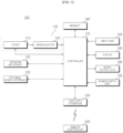
- FIG. 2 is an internal block diagram of the image display device of FIG. 1 .
- the image display device 100 may include a broadcast receiver 105, an external device interface 130, a network interface 135, a memory 140, a user input interface 150, an input unit 160, a controller 170, a display 180, an audio output unit 185, and/or a power supply unit 190.
- the broadcast receiver 105 may include a tuner 110 and a demodulator 120.
- the image display device 100 may include only the broadcast receiver 105 and the external device interface 130, among the broadcast receiver 105, the external device interface 130, and the network interface 135. That is, the image display device 100 may not include the network interface 135.
- the tuner 110 may select a broadcast signal corresponding to a channel selected by a user or broadcast signals corresponding to all prestored channels from among broadcast signals received via an antenna (not shown) or a cable (not shown).
- the tuner 110 may convert a selected broadcast signal into an intermediate frequency (IF) signal or a baseband video or audio signal.
- IF intermediate frequency
- the tuner 110 may convert the selected broadcast signal into a digital IF signal (DIF), and if the selected broadcast signal is an analog broadcast signal, the tuner 100 may convert the selected broadcast signal into an analog baseband video or audio signal CVBS/SIF. That is, the tuner 110 may process digital broadcast signals or analog broadcast signals.
- the analog baseband video or audio signal CVBS/SIF output from the tuner 110 may be directly input to the controller 170.
- the tuner 110 may sequentially select broadcast signals of all the broadcast channels stored through a channel memory function from among the received broadcast signals and may convert the selected broadcast signals into intermediate frequency (IF) signals or baseband video or audio signals.
- IF intermediate frequency
- the tuner 110 may include a plurality of tuners for receiving broadcast signals of a plurality of channels.
- the tuner 110 may be a single tuner that simultaneously receives broadcast signals of a plurality of channels.
- the demodulator 120 may receive a digital IF signal DIF converted by the tuner 110 and may demodulate the digital IF signal.
- the demodulator 120 may output a stream signal TS.
- the stream signal may be a multiplexed video signal, audio signal or data signal.
- the stream signal output from the demodulator 120 may be input to the controller 170.
- the controller 170 may output an image to the display 180 and may output sound to the audio output unit 185.
- the external device interface 130 may transmit or receive data to or from a connected external device (not shown). To this end, the external device interface 130 may include an A/V input/output unit (not shown).
- the external device interface 130 may be connected by wire/wirelessly to external devices, such as a digital versatile disc (DVD) player, a Blu-ray player, a game console, a camera, a camcorder, a computer (laptop), a set-top box, etc., and may perform input/output operations for external devices.
- DVD digital versatile disc
- Blu-ray Blu-ray
- game console a camera
- camcorder a computer (laptop), a set-top box, etc.
- the external device interface 130 may establish a communication network with various remote controllers 200 as illustrated in FIG. 1 , and may receive control signals related to operation of the image display device 100 from the remote controller 200 or may transmit data related to operation of the image display device 100 to the remote controller 200, through the established communication network.
- the A/V input/output unit may receive video and audio signals of an external device.
- the A/V input/output unit may include an Ethernet terminal, a USB port, a composite video banking sync (CVBS) terminal, a component terminal, an S-video terminal (analog), a digital visual interface (DVI) terminal, a high definition multimedia interface (HDMI) terminal, a mobile high-definition link (MHL) terminal, an RGB terminal, a D-SUB terminal, an IEEE 1394 terminal, an SPDIF terminal, a liquid HD terminal, etc.
- a digital signal input through such terminals may be transmitted to the controller 170.
- an analogue signal input through the CVBS terminal and the S-video terminal may be converted into a digital signal by an analogue/digital conversion unit (not shown), and then may be transmitted to the controller 170.
- the external device interface 130 may include a wireless communication unit (not shown) for short-range wireless communication with other electronic devices.
- the external device interface 130 may exchange data with an adjacent mobile terminal through the wireless communication unit.
- the external device interface 130 may receive device information, running application information, application image, and the like from the mobile terminal.
- the external device interface 130 may perform short-range wireless communication using Bluetooth, Radio Frequency Identification (RFID), infrared Data Association (IrDA), Ultra-Wideband (UWB), ZigBee, and the like.
- RFID Radio Frequency Identification
- IrDA infrared Data Association
- UWB Ultra-Wideband
- ZigBee ZigBee
- the network interface 135 may provide an interface for connecting the image display device 100 to a wired/wireless network including an Internet network.
- the network interface 135 may include a communication module (not shown) for connection with the wired/wireless network.
- the network interface 135 may include a communication module for Wireless LAN (WLAN; Wi-Fi), Wireless broadband (Wibro), World Interoperability for Microwave Access (Wimax), High Speed Downlink Packet Access (HSDPA), and the like.
- the network interface 135 may transmit or receive data to or from other users or other electronic devices through a connected network or another network linked to the connected network.
- the network interface 135 may receive web content or data provided by a content provider or a network operator. That is, the network interface 135 may receive the web content or data, such as movies, advertisements, games, VOD, broadcast signals, etc., as well as information related thereto, which are provided by content providers or network providers through the network.
- the network interface 135 may receive update information and an update file of firmware which are provided by network operators, and may transmit data to internet or content providers or network operators.
- the network interface 135 may select a desired application from among a plurality of applications open to the public, and may receive the selected application through a network.
- the memory 140 may store programs for processing and controlling each signal within the controller 180, and may store signal-processed video, audio or data signals.
- the memory 140 may store applications designed to perform various operations which may be processed by the controller 170, and in response to a request from the controller 170, the memory 140 may selectively provide some of the stored applications.
- the programs and the like stored in the memory 140 are not particularly limited, as long as the programs may be executed by the controller 170.
- the memory 140 may also perform the function of temporarily storing video, audio or data signals received from an external device through the external device interface 130.
- the memory 140 may store information on predetermined broadcast channels through a channel memory function, such as channel map and the like.
- FIG. 2 illustrates an example in which the memory 140 is provided separately from the controller 170, the scope of the present disclosure is not limited thereto, and the memory 140 may be included in the controller 170.
- the memory 140 may include at least one of a volatile memory (e.g., DRAM, SRAM, SDRAM, etc.) and a non-volatile memory (e.g., flash memory, hard disk type memory (HDD), solid-state drive (SSD), etc.). In various embodiments of the present disclosure, the memory 140 and the memory may be used interchangeably.
- a volatile memory e.g., DRAM, SRAM, SDRAM, etc.
- a non-volatile memory e.g., flash memory, hard disk type memory (HDD), solid-state drive (SSD), etc.
- HDD hard disk type memory
- SSD solid-state drive
- the user input interface 150 may transmit a signal, input by a user, to the controller 170 or may transmit a signal, input from the controller 170, to the user.
- the user input interface 150 may transmit/receive a user input signal, such as power on/off, channel selection, screen setup, etc., to/from the remote controller 250, and may transmit a user input signal input through a local key (not shown), such as a power key, a channel key, a volume key, or a setup value, etc., to the controller 170, or may transmit a user input signal, input from a sensor unit (not shown), which senses a user's gesture, to the controller 170, or may transmit a signal from the controller 170 to the sensor unit.
- a local key such as a power key, a channel key, a volume key, or a setup value, etc.
- the input unit 160 may be provided on one side of a main body of the image display device 100.
- the input unit 160 may include a touchpad, a physical button, and the like.
- the input unit 160 may receive various user commands associated with the operation of the image display device 100, and may transmit a control signal corresponding to the input command to the controller 170.
- the input unit 160 may include at least one microphone (not shown), and may receive a user's speech through the microphone.
- the controller 170 may include at least one processor, and by using the included processor, the controller 170 may control the overall operation of the image display device 100.
- the processor may be a general processor such as a central processing unit (CPU).
- the processor may be a dedicated device, such as an ASIC, or other hardware-based processor.
- the controller 170 may demultiplex the stream signal received from the tuner 110, the demodulator 120, the external device interface 130, or the network interface 135 into a number of signals, or may process the demultiplexed signals into video or audio data and output the video or audio data.
- the display 180 may convert a video signal, a data signal, an OSD signal, and a control signal processed by the controller 170 or a video signal, a data signal and a control signal received from the external device interface 130 to generate diving signals.
- the display 180 may include a display panel (not shown) including a plurality of pixels.
- the plurality of pixels included in the display panel may have RGB sub-pixels.
- the plurality of pixels included in the display panel may have RGBW sub-pixels.
- the display 180 may convert the video signal, data signal, OSD signal, control signal, and the like processed by the controller 170 to generate signals for driving the plurality of pixels.
- the display 180 may be a Plasma Display Panel (PDP), a Liquid Crystal Display (LCD), an Organic Light Emitting Diode (OLED), a flexible display, or the like, and may also be a three-dimensional (3D) display.
- the 3D display 180 may be divided into an autostereoscopic display and a glasses-type display.
- the display 180 may be configured as a touchscreen to be used as an input device in addition to an output device.
- the audio output unit 185 may receive an audio signal processed by the controller 170, and outputs the audio signal as sound.
- the image signal processed by the controller 170 may be input to the display 180 to be displayed as an image corresponding to the image signal. Further, the image signal processed by the controller 170 may be input to an external output device through the external device interface 130.
- the audio signal processed by the controller 170 may be output as sound to the audio output unit 185. Further, the audio signal processed by the controller 170 may be input to an external output device through the external device interface 130.
- the controller 170 may include a demultiplexer, a video processor, etc., which will be described later with reference to FIG. 3 .
- the controller 170 may control the overall operation of the image display device 100.
- the controller 170 may control the tuner 110 to tune in to a broadcast channel selected by a user or a prestored channel.
- controller 170 may control the image display device 100 according to a user command input through the user input interface 150 or an internal program.
- the controller 170 may control the display 180 to display images.
- the images displayed on the display 180 may be still images or moving images and may be 2D images or 3D images.
- the controller 170 may control a predetermined 2D object to be displayed in an image displayed on the display 180.
- the object may be at least one of an accessed web screen (newspaper, magazine, etc.), an electronic program guide (EPG), various menus, a widget, an icon, a still image, a moving image, and text.
- EPG electronic program guide
- the image display device 100 may further include an image capturing unit (not shown).
- the image capturing unit may capture images of a user.
- the image capturing unit may be implemented with one camera, but is not limited thereto, and may also be implemented with a plurality of cameras. Further, the image capturing unit may be embedded in the image display device 100 on the top of the display 180, or may be provided separately. Image information captured by the image capturing unit may be input to the controller 170.
- the controller 170 may recognize a user's position based on the images captured by the image capturing unit. For example, the controller 170 may identify a distance (z-axis coordinates) between the user and the image display device 100. In addition, the controller 170 may identify x-axis coordinates and y-axis coordinates corresponding to a user's position in the display 180.
- the controller 170 may sense a user's gesture based on the images captured by the image capturing unit or the respective signals sensed by the sensor unit, or a combination thereof.
- the power supply unit 190 may supply power throughout the image display device 100. Particularly, the power supply unit 190 may supply power to the controller 170 implemented in the form of a system on chip (SOC), the display 180 for image display, the audio output unit 185 for audio output, and the like.
- SOC system on chip
- the power supply unit 190 may include a converter for converting AC power into DC power and a DC/DC converter (not shown) for changing a DC power level.
- the remote controller 200 transmits a user input to the user input interface 150.
- the remote controller 200 may use Bluetooth, radio frequency (RF) communication, infrared (IR) communication, Ultra Wideband (UWB), ZigBee, and the like.
- the remote controller 200 may receive video, audio or data signals output from the user input interface 150, and may display the received signals or output the same as sound through the remote controller 200.
- the aforementioned image display device 100 may be a fixed type or movable digital broadcast receiver capable of receiving digital broadcast.
- the block diagram of the image display device 100 illustrated in FIG. 2 is merely a block diagram for an embodiment of the present disclosure. Components of the block diagram may be integrated, added or omitted according to specifications of the actually implemented image display device 100.
- FIG. 3 is an internal block diagram of the controller of FIG. 2 .
- the controller 170 may include a demultiplexer 310, an image processor 320, a processor 330, an OSD generator 340, a mixer 345, a frame rate converter 350, and/or a formatter 360. Besides, the controller 170 may further include an audio processor (not shown) and a data processor (not shown).
- the demultiplexer 310 demultiplexes the input stream. For example, when an MPEG-2 TS is input, the demultiplexer 310 may demultiplex the MPEG-2 TS into video, audio, and data signals, respectively.
- the stream signal input to the demultiplexer 310 may be a stream signal output from the tuner unit 110, the demodulator 120, or the external device interface 130.
- the image processor 320 may perform image processing on the demultiplexed video signal. To this end, the image processor 320 may include an image decoder 325 and a scaler 335.
- the image decoder 325 decodes the demultiplexed video signal, and the scaler 335 performs scaling so that the resolution of the decoded video signal may be output to the display 180.
- the image decoder 325 may include a decoder of various standards. For example, a 3D image decoder for MPEG-2, H.264 decoder, a color image, and a depth image, and a decoder for a multiple view image may be provided.
- the processor 330 may control the overall operation of the image processing device 100 or the controller 170. For example, the processor 330 may control the tuner 110 to tune in to an RF broadcast channel selected by a user or a prestored channel.
- the processor 330 may control the image display device 100 by a user command input through the user input interface 150 or an internal program.
- the processor 330 may control data transmission with the network interface 135 or the external device interface 130.
- the processor 330 may control operations of the demultiplexer 310, the image processor 320, the OSD generator 340, and the like in the controller 170.
- the OSD generator 340 generates an OSD signal according to a user input or by itself. For example, based on a user input signal input through the input unit 160, the OSD generator 340 may generate a signal for displaying a variety of information as a graphic or a text on the screen of the display 180.
- the generated OSD signal may include various data such as a user interface screen of the image display device 100, various menu screens, a widget, and an icon.
- the generated OSD signal may include a 2D object or a 3D object.
- the OSD generator 340 may generate a pointer that may be displayed on the display, based on a pointing signal input from the remote controller 200.
- the OSD generator 340 may include a pointing signal processing unit (not shown) for generating a pointer.
- the pointing signal processing unit (not shown) may be provided separately, rather than being provided in the OSD generator 240.
- the mixer 345 may mix an OSD signal generated by the OSD generator 340 with a decoded image signal image-processed by the image processor 320.
- the mixed image signal may be supplied to the frame rate converter 350.
- the frame rate converter (FRC) 350 may convert the frame rate of an input image. Meanwhile, the frame rate converter 350 may also directly output the frame rate without any additional frame rate conversion.
- the formatter 360 may arrange a left-eye video frame and a right-eye video frame of the 3D video signal subjected to frame rate conversion. Further, a synchronization signal Vsync may be output for opening the left-eye glass and the right-eye glass of the 3D viewing device (not shown).
- the formatter 360 may convert the format of an input image signal into an image signal to be displayed and output on the display 180.
- the formatter 360 may change the format of a 3D image signal.
- the formatter 360 may change the format of the 3D image signal into any one of various 3D formats such as a side by side format, a top/down format, a frame sequential format, an interlaced format, a checker box format, and the like.
- the formatter 360 may convert a 2D video signal into a 3D video signal.
- the formatter 360 may detect an edge or a selectable object from the 2D video signal and separate an object according to the detected edge or the selectable object as a 3D video signal to thereby generate the 3D video signal according to a 3D video generation algorithm.
- the generated 3D video signal may be separated into a left-eye video signal L and a right-eye video signal R and aligned as described above.
- a 3D processor for 3-dimensional (3D) effect signal processing may be further provided following the formatter 360.
- Such a 3D processor may control brightness, tint and color of a video signal for 3D effect enhancement.
- the 3D processor may perform signal processing for making a close-range view clear and blurring a distant view.
- the function of the 3D processor may be integrated with the formatter 360 or the image processor 320.
- the audio processor (not shown) included in the controller 170 may process a demultiplexed audio signal.
- the audio processor (not shown) may include various decoders.
- the audio processor included in the controller 170 may control base, treble, volume, and the like.
- the data processor included in the controller 170 may process the demultiplexed data signal.
- the demultiplexed data signal is an encoded data signal
- the encoded data signal may be decoded.
- the encoded data signal may be electronic program guide (EPG) information including broadcast information such as start time and finish time of a broadcast program that is broadcast through each channel.
- EPG electronic program guide
- FIG. 3 the block diagram of the controller 170 illustrated in FIG. 3 is merely a block diagram for an embodiment of the present disclosure, and components of the block diagram may be integrated, added, or omitted according to the specifications of the actually implemented controller 170.
- each of the frame rate converter 350 and the formatter 360 may be separately provided instead of being included in the controller 170, or may be provided separately as one module.
- FIG. 4 is a diagram illustrating a method of controlling the remote controller of FIG. 2 .
- a pointer 205 corresponding to the remote controller 200 is displayed on the display 180 of the image display device 100.
- a user may move or rotate the remote controller 200 up and down, left and right, and back and forth.
- the pointer 205 displayed on the display 180 may be displayed according to movement of the remote controller 200.
- the remote controller 200 may be referred to as a spatial remote controller or a 3D pointing device, because the pointer 205 corresponding thereto is moved and displayed according to movement in a 3D space, as illustrated in the drawing.
- Information on movement of the remote controller 200 detected by a sensor of the remote controller 200 may be transmitted to the image display device 100.
- the image display device 100 may calculate coordinates of the pointer 205 based on the information on the movement of the remote controller 200.
- the image display device 100 may display the pointer 205 corresponding to the calculated coordinates.
- a user moves the remote controller 200 away from the display 180 while pressing a specific button on the remote controller 200.
- a selected area on the display 180 corresponding to the points 205 may be zoomed in and thus magnified.
- a selected area on the display 180 corresponding to the points 205 may be zoomed out and thus reduced.
- the selected area may be zoomed out, and when the remote controller 200 approaches the display 180, the selected area may be zoomed in.
- up/down movement and left/right movement may not be recognized. That is, when the remote controller 200 moves away from or closer to the display 180, up/down movement and left/right movement may not recognized, but only the forward/backward movement may be recognized.
- the specific button of the remote controller 200 only the up/down movement and left/right movement of the remote controller 200 may be recognized, and only the pointer 205 may move accordingly.
- a moving speed or moving direction of the pointer 205 may correspond to a moving speed or moving direction of the remote controller 200.
- FIGS. 5 and 6 are diagrams referred to in the description of a display of FIG. 2 .
- the display 180 may include a display panel 210 and a panel driver 230.
- the display panel 210 may include a plurality of pixels P.
- the plurality of pixels P may be connected to a plurality of gate lines GL and data lines DL that intersect in a matrix form.
- a plurality of thin film transistors (TFTs) may be disposed at the intersection of the plurality of gate lines GL and data lines DL.
- the plurality of pixels P may be formed at the intersection of the plurality of data lines DL and the plurality of gate lines GL.
- Each of the plurality of pixels P may be connected to the data line and the gate line.
- the plurality of pixels may include a liquid crystal layer
- the plurality of pixels may include an organic light emitting diode (OLED).
- the display panel 210 may include a first substrate on which a driving element, such as a thin film transistor (TFT), and a pixel electrode connected thereto are formed, a second substrate on which a common electrode is formed, and a liquid crystal layer formed between the first substrate and the second sub strate.
- a driving element such as a thin film transistor (TFT)
- TFT thin film transistor
- the panel driver 230 may drive the display panel 180 based on the control signal and the data signal transmitted from the controller 170.
- the panel driver 230 may include a timing controller 232, a gate driver 234 and/or a data driver 236.
- the timing controller 232 may receive a control signal, an image signal, and the like from the controller 170.
- the timing controller 232 may receive an RGB signal, a vertical synchronization signal Vsync, and the like from the controller 170.
- the timing controller 232 may control the gate driver 234 and/or the data driver 236 in response to the control signal.
- the timing controller 232 may rearrange the image signal according to specifications of the data driver 236 and transmit it to the data driver 236.
- the gate driver 234 and the data driver 236 may supply a scan signal and an image signal to the display panel 210 through the gate lines GL and the data lines DL under the control of the timing controller 232.
- the data driver 236 may include a plurality of source driver integrated circuits (ICs) corresponding to the plurality of data lines DL.
- ICs source driver integrated circuits
- the display 180 may further include a backlight unit 250 and/or a backlight dimming controller 260.
- the backlight unit 250 supplies light to the display panel 210.
- the backlight unit 250 may include at least one light source 252 configured to output light, a scan driver 254 configured to control scan driving of the light source 252, and/or a light source driver 256 configured to turn on/off the light source 252.
- the display 180 may display a predetermined image by using light output from the backlight unit 250 while light transmittance of the liquid crystal layer is adjusted by an electric field generated between the pixel electrode and the common electrode of the display panel 210.
- the power supply unit 190 may supply a common electrode voltage Vcom to the display panel 210, and may supply a gamma voltage to the data driver 236. In addition, driving power for driving the light source 252 may be supplied to the backlight unit 250.
- the display 180 may be driven by local dimming.
- the backlight unit 250 may be divided into a plurality of blocks.
- the backlight unit 250 may be driven for each of the divided blocks.
- the display panel 210 may have a plurality of divided areas corresponding to each of the blocks of the backlight unit 250.
- the brightness of light emitted from each of the blocks of the backlight unit 250 may be adjusted according to a luminance level, e.g., a peak value of a gray level or a color coordinate signal, of each of the divided areas of the display panel 210.
- the image display device 100 may decrease the brightness of light emitted from a block corresponding to the dark part of the image and may increase the brightness of light emitted from a block corresponding to the bright part of the image, among the blocks of the backlight unit 250. In this manner, the contrast ratio and sharpness of the image output by the image display device 100 may be improved.
- the image display device 100 may control the display 180 to perform local dimming by setting a dimming value for each of the blocks of the backlight unit 250.
- the timing controller 232 may output an RGB signal to the backlight dimming controller 510.
- the backlight dimming controller 510 may calculate the dimming value of each of the blocks of the backlight unit 250, based on the RGB signal received from the timing controller 232.
- the backlight dimming controller 510 may determine the luminance level for the entire area and/or a partial area of the image based on the RGB signal. For example, the backlight dimming controller 805 may determine an average luminance level (average picture level: APL) for each of the plurality of divided areas corresponding to each of the blocks of the backlight unit 550, an average luminance level for the entire area of image, and the like.
- APL average luminance level
- the backlight dimming controller 510 may calculate a dimming value of each of the blocks of the backlight unit 250 based on the luminance level of the entire area and/or partial area of the image. For example, the backlight dimming controller 510 may calculate a dimming value of each of the blocks of the backlight unit 250 based on the luminance level of each of the plurality of divided areas, the luminance level of a surrounding area, the luminance level of the entire area, and the like.
- the backlight dimming controller 510 may calculate the dimming value so that the brightness of light emitted from the block in the area with a low luminance level decreases, and the brightness of light emitted from the block in the area with a high luminance level increases, among the blocks of the backlight unit 250.
- timing controller 232 and the backlight dimming controller 510 may be provided separately from each other or may be provided as one module. Alternatively, the timing controller 232 and the backlight dimming controller 510 may be included in the controller 170.
- the backlight dimming controller 510 may output the calculated dimming value to the backlight unit 250.
- the backlight dimming controller 510 may output a signal including the calculated dimming value to the backlight unit 250.
- the backlight unit 250 may adjust the intensity of light emitted from the light source 252, based on the dimming value received from the backlight dimming controller 510.
- the backlight unit 250 may be implemented as a direct-type backlight unit.
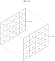
- the display panel 210 may be composed of a plurality of divided areas.
- FIG. 6 illustrates an example in which the display panel 210 is equally divided into 16 divided areas BL1 to BL16, but it is not limited thereto.
- Each of the plurality of divided areas BL1 to BL16 may include a plurality of pixels.
- the backlight unit 250 may have a structure in which a plurality of optical sheets and a diffusion plate are stacked below the display panel 210, and a plurality of light sources are disposed below the diffusion plate.
- the blocks B1 to B16 of the backlight unit 250 may respectively correspond to the divided areas BL1 to BL16 of the display panel 210.
- a first block B1 of the backlight unit 250 may correspond to a first divided area BL1 of the display panel 210.
- the brightness of light incident on the first divided area BL1 of the display panel 210 may be adjusted by the light source 252 included in the first block B1 of the backlight unit 250 disposed at a position corresponding to the first divided area BL1 of the display panel 210.
- the light source 252 provided in the blocks B1 to B16 of the backlight unit 250 may be implemented as point light sources such as a light emitting diode (LED).
- LED light emitting diode
- the light source 252 may be turned on or off according to a driving signal received from the light source driver 256.
- the light source driver 256 may generate a driving signal based on the dimming value output from the backlight dimming controller 260.
- the driving signal may be a pulse width modulation (PWM) signal.
- PWM pulse width modulation
- the brightness of light emitted from the light source 252 may be adjusted according to an amplitude of the driving signal received from the light source driver 256.
- the time during which light is emitted from the light source 252 may be adjusted according to the pulse width of the driving signal received from the light source driver 256.
- the backlight unit 250 may include a plurality of driving units 250a to 250n.
- the plurality of driving units 250a to 250n may receive dimming values calculated for a plurality of blocks, a vertical synchronization signal Vsync corresponding to one frame, and the like from the backlight dimming controller 260.
- the plurality of driving units 250a to 250n may receive signals using Serial Peripheral Interface (SPI) communication.
- SPI Serial Peripheral Interface
- the plurality of driving units 250a to 250n may receive dimming values calculated for a plurality of blocks, a vertical synchronization signal Vsync corresponding to one frame, and the like.
- the plurality of driving units 250a to 250n may receive signals using Serial Peripheral Interface (SPI) communication.
- SPI Serial Peripheral Interface
- the plurality of driving units 250a to 250n may include light source drivers 256a to 256n and/or a plurality of light sources 252a to 252n.
- Each of the light source drivers 256a to 256n may include at least one driver IC.
- Each of a plurality of driver ICs may output a driving signal for controlling the brightness of n blocks by using n channels.
- Each of the plurality of driver ICs may output a driving signal for adjusting the brightness of the light source 252, based on the dimming value calculated for the plurality of blocks. For example, in the case where each driver IC outputs a driving signal by using 16 channels, each driver IC may adjust the brightness of the light source 252 included in 16 blocks.
- the first light source driver 256a may adjust the brightness of the light sources 252 included in 4x16, i.e., 64 blocks, among the divided blocks of the backlight unit 250.
- Each of the plurality of driving units 250a to 250n may include a substrate.
- the substrate may be a printed circuit board (PCB).
- Components included in the plurality of driving units 250a to 250n for example, driver ICs, may be respectively mounted on a plurality of substrates corresponding to the plurality of driving units 250a to 250n.
- Substrates corresponding to the plurality of driving units 250a to 250n may be disposed adjacent to each other in the order of the divided blocks of the backlight unit 250.
- the plurality of driving units 250a to 250n may further include a Digital Analog Converter (DAC).
- DAC Digital Analog Converter
- the DAC may convert a digital dimming value into an analog value and output the analog value to the driver IC.
- each of the plurality of driving units 250a to 250n may receive a signal from the backlight dimming controller 260.
- each of the plurality of driving units 250a to 250n may be electrically connected to the backlight dimming controller 260 through cables 710 to 760 corresponding to the plurality of driving units 250a to 250n.
- the cables 710 to 760 corresponding to the plurality of driving units 250a to 250n may be respectively connected to connectors mounted on substrates corresponding to the plurality of driving units 250a to 250n.
- a vertical synchronization signal Vsync corresponding to a frame output period and dimming values Data corresponding to the brightness of blocks when each frame is output may be input to each of the plurality of driving units 250a to 250n through the cables 710 to 760 corresponding to the plurality of driving units 250a to 250n.
- Each of the plurality of driving units 250a to 250n may adjust the brightness of the light sources 252 included in the blocks constituting each of the plurality of driving units 250a to 250n, based on the vertical synchronization signal Vsync and the dimming values Data which are received through the cables 710 to 760.
- the backlight dimming controller 260 may be connected to each of the 12 driving units through cables 901 to 912. In this case, as a spacing distance from the backlight dimming controller 260 increases, the length of cables connected to the driving units may increase.
- the length of the cables 901 to 912 may increase depending on the arrangement of other components included in the image display device 100.
- second and fourth cables 902 and 904 may be disposed adjacent to a side portion of the image display device 100 along the edge of the first region 910.
- tenth and twelfth cables 910 and 912 connected to tenth and twelfth driving units may be disposed along the edge of the second region 920.
- the length thereof increases compared to the case where the cables are disposed across the first region 910.
- the tenth and twelfth cables 910 and 912 are disposed along the edge of the second region 920, the length thereof increases compared to the case where the cables are disposed across the second region 920.
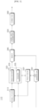
- the backlight unit 250 of the image display device 100 may be composed of a plurality of groups 1001 to 1003 each including two or more of the plurality of driving units 250a to 250n.
- the present disclosure an example is illustrated in which two driving units are included in each of the plurality of groups 1001 to 1003, but the present disclosure is not limited thereto.
- three or more driving units may be included in each of the plurality of groups 1001 to 1004.
- the backlight dimming controller 260 may output signals corresponding to the plurality of groups 1001 to 1003.
- the backlight dimming controller 260 may output signals through cables 1010, 1030, and 1050 respectively corresponding to three groups that are electrically connected to the backlight dimming controller 260.
- the cables 1010, 1030, and 1050 electrically connected to the backlight dimming controller 260 may be referred to as main cables.
- the main cables 1010, 1030, and 1050 may be electrically connected to main driving units 250a, 250c, and 250m, respectively, among the plurality of driving units 250a to 250n included in the plurality of groups 1001 to 1003.
- a first main cable 1010 may be connected to each of a connector, mounted on a substrate corresponding to the backlight dimming controller 260, and a connector mounted on a substrate corresponding to a first main driving unit 250a included in a first group 1001.
- sub-driving units may be electrically connected to each other.
- the cables 1020, 1040, and 1060 that electrically connect the driving units 250a to 250n included in each of the plurality of groups 1001 to 1003 may be referred to as sub-cables.
- a first sub-cable 1020 may be connected to each of a connector mounted on a substrate corresponding to the first main driving unit 250a included in the first group 1001, and a connector mounted on a substrate corresponding to a second sub-driving unit 250b.
- the main driving units 250a, 250c, and 250m and the sub-driving units 250b, 250d, and 250n may be disposed adjacent to each other.
- a substrate corresponding to the first main driving unit 250a and a substrate corresponding to a first sub-driving unit 250b may be disposed adjacent to each other.
- the signals output from the backlight dimming controller 260 may be output to the respective groups 1001 to 1003 through the main cables 1010, 1030, and 1050.
- the signals transmitted through the main cables 1010, 1030, and 1050 may be input to the main driving units 250a, 250c, and 250m.
- the backlight dimming controller 260 may output signals H and L respectively corresponding to the main driving units 250a, 250c, and 250m and the sub-driving units 250b, 250d, and 250n which are included in the plurality of groups 1001 to 1003.
- the signal H corresponding to the main driving units 250a, 250c, and 250n may be referred to as a main signal
- the signal L corresponding to the sub-driving units 250b, 250d, and 250n may be referred to as a sub-signal.
- a signal that is output by the backlight dimming controller 260 for the first group 1001 may include the main signal H corresponding to the first main driving unit 250a and the sub-signal L corresponding to the first sub-driving unit 250b.
- the signals transmitted through the main cables 1010, 1030, and 1050 may be transmitted as they are through the sub-cables 1020, 1040, and 1060.
- the vertical synchronization signal Vsync, the dimming values Data, the main signal H, and the sub-signal L may be transmitted as they are to the first sub-driving unit 250b through the first sub-cable 1020.
- the main cables 1010, 1030, and 1050 and/or the sub-cables 1020, 1040, and 1060 may be flat flexible cables (FFCs).
- the vertical synchronization signal Vsync corresponding to a frame output period, the dimming values Data corresponding to the brightness of blocks when each frame is output, and the main signal H, and the sub-signal L may be input through the main cables 1010, 1030, and 1050 to each of the main driving units 250a, 250c, and 250m among the plurality of driving units 250a to 250n.
- the main driving units 250a, 250c, and 250m may determine, based on the main signal H, dimming values of blocks corresponding to the main driving units 250a, 250c, and 250m, among dimming values Data transmitted through the main cables 1010, 1030, and 1050.
- the main driving units 250a, 250c, and 250m may determine dimming values, transmitted in a period in which the main signal H is high, to be dimming values of the blocks corresponding to the main driving units 250a, 250c, and 250m, among the dimming values Data transmitted through the main cables 1010, 1030, and 1050.
- the main driving units 250a, 250c, and 250m may adjust brightness of the light sources 252 included in the blocks constituting the main driving units 250a, 250c, and 250m, based on the vertical synchronization signal Vsync received through the main cables 1010, 1030, and 1050 and the dimming values of the blocks corresponding to the main driving units 250a, 250c, and 250m.
- the vertical synchronization signal Vsync, the dimming values Data, the main signal H, and the sub-signal L, which are transmitted through the main cables 1010, 1030, and 1050 may be input through the sub-cables 1020, 1040, and 1060 to each of the sub-driving units 250b, 250d, and 250n among the plurality of driving units 250a to 250n.
- the sub-driving units 250b, 250d, and 250n may determine, based on the sub-signal L, dimming values of the blocks corresponding to the sub-driving units 250b, 250d, and 250n among the dimming values Data transmitted through the sub-cables 1020, 1040, and 1060.
- the sub-driving units 250b, 250d, and 250n may determine dimming values, transmitted in a period in which the sub-signal L is high, to be dimming values of the blocks corresponding to the sub-driving units 250b, 250d, and 250n, among the dimming values Data transmitted through the sub-cables 1020, 1040, and 1060.
- the sub-driving units 250b, 250d, and 250n may adjust brightness of the light sources 252 included in the blocks constituting the sub-driving units 250b, 250d, and 250n, based on the vertical synchronization signal Vsync received through the sub-cables 1020, 1040, and 1060 and dimming values of the blocks corresponding to the sub-driving units 250b, 250d, and 250n.
- the period in which the main signal H is high and the period in which the sub-signal L is high may not overlap each other. That is, in response to an end of the period in which either one of the main signal H and the sub-signal L is high, the period in which a remaining one of the main signal H and the sub-signal L is high may be initiated.
- dimming values transmitted in the period in which the main signal H is high are determined to be dimming values of the blocks corresponding to the main driving units 250a, 250c, and 250m
- dimming values transmitted in the period in which the sub-signal L is high are determined to be dimming values of the blocks corresponding to the sub-driving units 250b, 250d, and 250n, but the present disclosure is not limited thereto.
- dimming values transmitted in a period in which the main signal H is low may be determined to be dimming values of the blocks corresponding to the main driving units 250a, 250c, and 250m
- dimming values transmitted in a period in which the sub-signal L is low may be determined to be dimming values of the blocks corresponding to the sub-driving units 250b, 250d, and 250n.
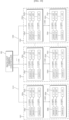
- the backlight unit 250 may be composed of six groups each including two driving units.
- each of the six groups may include one main driving unit and one sub-driving unit.
- the backlight dimming controller 260 may be connected to each of six main cables 1201, 1203, 1205, 1207, 1209, and 1211.
- the six main cables 1201, 1203, 1205, 1207, 1209, and 1211 may be connected to six main driving units, respectively.
- the six main cables 1201, 1203, 1205, 1207, 1209, and 1211 may be connected to a first connector mounted on each of six substrates corresponding to the main driving units.
- the six main driving units may be connected to six sub-cables 1202, 1204, 1206, 1208, 1210, and 1212, respectively.
- the six sub-cables 1202, 1204, 1206, 1208, 1210, and 1212 may connect a second connector mounted on each of the six substrates corresponding to the main driving units, and a third connector mounted on each of the six substrates corresponding to the sub-driving units.
- the first connector to which the main cables 1201, 1203, 1205, 1207, 1209, and 1211 are connected, may be positioned on a substrate adjacent to the backlight dimming controller 260.
- the first connector may be mounted adjacent to an upper side of a substrate corresponding to the main driving unit.
- the second connector and the third connector, to which the sub-cables 1202, 1204, 1206, 1208, 1210, and 1212 are connected may be disposed adjacent to each other.
- the second connector may be disposed adjacent to a lower side of a substrate corresponding to the main driving unit
- the third connector may be disposed adjacent to an upper side of a substrate corresponding to a sub-driving unit.
- the lengths of the cables may be relatively reduced compared to the case where the backlight dimming controller 260 is connected to each of the plurality of driving units. In this manner, it is possible to minimize noise components included in signals transmitted to the plurality of driving units. Further, it is possible to reduce impedance of the cables for transmitting signals to the plurality of driving units, thereby improving performance related to power consumption of the image display device 100 and the like.
- connection structure between components provided for adjusting the intensity of light emitted by the light source 252 may be simplified.
- the length of a signal line configured to transmit signals to the backlight unit 250 may be minimized.
- the method of operating the image display device of the present disclosure may be implemented as code that can be written to a processor-readable recording medium and can thus be read by a processor included in the image display device.
- the processor-readable recording medium may be any type of recording device in which data can be stored in a processor-readable manner. Examples of the processor-readable recording medium include a ROM, a RAM, a CD-ROM, a magnetic tape, a floppy disk, an optical data storage, and a carrier wave, e.g., data transmission over the Internet.
- the processor-readable recording medium can be distributed over a plurality of computer systems connected to a network so that processor-readable code is written thereto and executed therefrom in a decentralized manner.
Landscapes
- Engineering & Computer Science (AREA)
- Physics & Mathematics (AREA)
- Computer Hardware Design (AREA)
- General Physics & Mathematics (AREA)
- Theoretical Computer Science (AREA)
- Control Of Indicators Other Than Cathode Ray Tubes (AREA)
Abstract
Description
- The following description relates to an image display device.
- An image display device is a device having the function of displaying images that are viewable by users. Typical examples of the image display device include a liquid crystal display (LCD) device using liquid crystal, an organic light-emitting diode (OLED) display device using OLEDs, and the like.
- Among them, the LCD device includes a liquid crystal layer and displays an image by controlling an electric field applied to the liquid crystal layer and modulating light emitted by a light source of a backlight unit. Recently, a local dimming method using multiple light sources is used in order to reduce power consumption of the backlight unit and to improve the contrast ratio and sharpness of an image. The local dimming method may include dividing input image data into virtual screen areas which are divided in a matrix form on a display panel, and classifying light sources of the backlight unit according to screen areas. In this case, the method may be a method of locally controlling luminance of each screen area by adjusting brightness of the respective light sources of the backlight unit according to a representative value for each screen area.
- Meanwhile, as an area of the display panel provided in the image display device increases, the number of light sources included in the backlight unit may increase, and a distance between a component for outputting a control signal according to the local dimming method and a component for adjusting the brightness of the light sources according to the control signal may increase. As a result, problems occur in that a connection structure between the respective components becomes complicated, and impedance of a signal line for transmitting a signal to the backlight unit increases. In addition, there is also a problem in that due to the increase in length of the signal line, electromagnetic waves and the like generated in other components may increase the possibility of noise components occurring in the signal line.
- It is an objective of the present disclosure to solve the above and other problems.
- It is another objective of the present disclosure to provide an image display device capable of simplifying a connection structure between components provided for adjusting the intensity of light emitted by a light source.
- It is yet another objective of the present disclosure to provide an image display device capable of minimizing the length of a signal line configured to transmit signals to a backlight unit.
- In order to achieve the above and other objectives, an image display device according to an embodiment of the present disclosure includes: a display panel; a backlight unit including a plurality of blocks composed of light sources; and a controller, wherein the backlight unit includes a plurality of driving units each including a driver integrated circuit (IC) configured to adjust an intensity of light emitted from the respective blocks, wherein the plurality of driving units include main driving units electrically connected to the controller through main cables, and sub-driving units electrically connected to the main driving units through sub-cables, wherein signals transmitted to the main driving units through the main cables are transmitted to the sub-driving units through the sub-cables, wherein the controller is configured to output, through the main cables, a first signal including a dimming value of each block that corresponds to the intensity of light emitted from each of the plurality of blocks, a second signal corresponding to the main driving unit, and a third signal corresponding to the sub-driving unit, wherein the main driving unit is configured to determine a first dimming value corresponding to the main driving unit from the first signal based on the second signal, and the sub-driving unit is configured to determine a second dimming value corresponding to the sub-driving unit from the first signal based on the third signal.
- An image display device according to the present disclosure has the following effects.
- According to at least one embodiment of the present disclosure, a connection structure between components provided for adjusting the intensity of light emitted by a light source may be simplified.
- According to at least one embodiment of the present disclosure, the length of a signal line configured to transmit signals to a backlight unit may be minimized.
- Further scope of applicability of the present disclosure will become apparent from the detailed description given hereinafter. However, it should be understood that the detailed description and specific examples, while indicating preferred embodiments of the present disclosure, are given by illustration only, since various changes and modifications within the spirit and scope of the present disclosure will become apparent to those skilled in the art from this detailed description.
-
-
FIG. 1 is a diagram illustrating an image display system according to various embodiments of the present disclosure. -
FIG. 2 is an internal block diagram of an image display device ofFIG. 1 . -
FIG. 3 is a diagram referred to in the description of a controller ofFIG. 2 . -
FIG. 4 is a diagram illustrating a method of controlling a remote controller ofFIG. 2 . -
FIGS. 5 and6 are diagrams referred to in the description of a display ofFIG. 2 . -
FIGS. 7 to 12 are diagrams referred to in the description of an image display device according to an embodiment of the present disclosure. - Hereinafter, the present disclosure will be described in detail with reference to the accompanying drawings. In order to clearly and briefly describe the present disclosure, components that are irrelevant to the description will be omitted in the drawings, and the same reference numerals are used throughout the drawings to designate the same or similar components.
- The terms "module" and "unit" for elements used in the following description are given simply in view of the ease of the description, and do not have a distinguishing meaning or role. Therefore, the "module" and "unit" may be used interchangeably.
- It should be understood that the terms "comprise", 'include", "have", etc. when used in this specification, specify the presence of stated features, integers, steps, operations, elements, components, or combinations thereof but do not preclude the presence or addition of one or more other features, integers, steps, operations, elements, components, or combinations thereof.
- It will be understood that, although the terms first, second, etc., may be used herein to describe various elements, these elements should not be limited by these terms. These terms are only used to distinguish one element from another.
-
FIG. 1 is a diagram illustrating an image display system according to various embodiments of the present disclosure. - Referring to
FIG. 1 , animage display system 10 includes animage display device 100 and/or aremote controller 200. - The
image display device 100 may be a device for processing and outputting images. Theimage display device 100 may be a TV, a notebook computer, a monitor, etc., and is not particularly limited as long as the image display device is capable of outputting a screen corresponding to an image signal. - The
image display device 100 may receive a broadcast signal and process the received signal, and may output a signal-processed broadcast image. In the case where theimage display device 100 receives the broadcast signal, theimage display device 100 may serve as a broadcast receiving device. - The
image display device 100 may receive the broadcast signal wirelessly through an antenna or by wire via cables. - For example, the
image display device 100 may receive a terrestrial broadcast signal, a satellite broadcast signal, a cable broadcast signal, an Internet Protocol TV (IPTV) broadcast signal, and the like. - The
remote controller 200 may be connected wirelessly and/or by wire with theimage display device 100 to provide various control signals to theimage display device 100. In this case, theremote controller 200 may include a device for establishing a wired/wireless network with theimage display device 100 and for transmitting various control signals to theimage display device 100 or for receiving, from theimage display device 100, signals related to various operations processed by theimage display device 100, through the established network. - For example, various input devices, such as a mouse, a keyboard, a pointing device, a trackball, a joystick, etc., may be used as the
remote controller 200. Theremote controller 200 may be referred to as an external device, and the external device and the remote controller will be used interchangeably as needed hereinafter. - The
image display device 100 may be connected to only a singleremote controller 200 or may be simultaneously connected to two or moreremote controllers 200, and may change an object displayed on a screen or adjust a screen state based on control signals provided by the respectiveremote controllers 200. -
FIG. 2 is an internal block diagram of the image display device ofFIG. 1 . - Referring to
FIG. 2 , theimage display device 100 may include abroadcast receiver 105, anexternal device interface 130, anetwork interface 135, amemory 140, auser input interface 150, aninput unit 160, acontroller 170, adisplay 180, anaudio output unit 185, and/or apower supply unit 190. - The
broadcast receiver 105 may include atuner 110 and ademodulator 120. - Meanwhile, unlike the drawing, the
image display device 100 may include only thebroadcast receiver 105 and theexternal device interface 130, among thebroadcast receiver 105, theexternal device interface 130, and thenetwork interface 135. That is, theimage display device 100 may not include thenetwork interface 135. - The
tuner 110 may select a broadcast signal corresponding to a channel selected by a user or broadcast signals corresponding to all prestored channels from among broadcast signals received via an antenna (not shown) or a cable (not shown). Thetuner 110 may convert a selected broadcast signal into an intermediate frequency (IF) signal or a baseband video or audio signal. - For example, if the selected broadcast signal is a digital broadcast signal, the
tuner 110 may convert the selected broadcast signal into a digital IF signal (DIF), and if the selected broadcast signal is an analog broadcast signal, thetuner 100 may convert the selected broadcast signal into an analog baseband video or audio signal CVBS/SIF. That is, thetuner 110 may process digital broadcast signals or analog broadcast signals. The analog baseband video or audio signal CVBS/SIF output from thetuner 110 may be directly input to thecontroller 170. - Meanwhile, the
tuner 110 may sequentially select broadcast signals of all the broadcast channels stored through a channel memory function from among the received broadcast signals and may convert the selected broadcast signals into intermediate frequency (IF) signals or baseband video or audio signals. - Meanwhile, the
tuner 110 may include a plurality of tuners for receiving broadcast signals of a plurality of channels. Alternatively, thetuner 110 may be a single tuner that simultaneously receives broadcast signals of a plurality of channels. - The
demodulator 120 may receive a digital IF signal DIF converted by thetuner 110 and may demodulate the digital IF signal. - Upon performing demodulation and channel decoding, the
demodulator 120 may output a stream signal TS. In this case, the stream signal may be a multiplexed video signal, audio signal or data signal. - The stream signal output from the
demodulator 120 may be input to thecontroller 170. Upon performing demultiplexing, video/audio signal processing, etc., thecontroller 170 may output an image to thedisplay 180 and may output sound to theaudio output unit 185. - The
external device interface 130 may transmit or receive data to or from a connected external device (not shown). To this end, theexternal device interface 130 may include an A/V input/output unit (not shown). - The
external device interface 130 may be connected by wire/wirelessly to external devices, such as a digital versatile disc (DVD) player, a Blu-ray player, a game console, a camera, a camcorder, a computer (laptop), a set-top box, etc., and may perform input/output operations for external devices. - In addition, the
external device interface 130 may establish a communication network with variousremote controllers 200 as illustrated inFIG. 1 , and may receive control signals related to operation of theimage display device 100 from theremote controller 200 or may transmit data related to operation of theimage display device 100 to theremote controller 200, through the established communication network. - The A/V input/output unit may receive video and audio signals of an external device. For example, the A/V input/output unit may include an Ethernet terminal, a USB port, a composite video banking sync (CVBS) terminal, a component terminal, an S-video terminal (analog), a digital visual interface (DVI) terminal, a high definition multimedia interface (HDMI) terminal, a mobile high-definition link (MHL) terminal, an RGB terminal, a D-SUB terminal, an IEEE 1394 terminal, an SPDIF terminal, a liquid HD terminal, etc. A digital signal input through such terminals may be transmitted to the
controller 170. In this case, an analogue signal input through the CVBS terminal and the S-video terminal may be converted into a digital signal by an analogue/digital conversion unit (not shown), and then may be transmitted to thecontroller 170. - The
external device interface 130 may include a wireless communication unit (not shown) for short-range wireless communication with other electronic devices. Theexternal device interface 130 may exchange data with an adjacent mobile terminal through the wireless communication unit. For example, in a mirroring mode, theexternal device interface 130 may receive device information, running application information, application image, and the like from the mobile terminal. - The
external device interface 130 may perform short-range wireless communication using Bluetooth, Radio Frequency Identification (RFID), infrared Data Association (IrDA), Ultra-Wideband (UWB), ZigBee, and the like. - The
network interface 135 may provide an interface for connecting theimage display device 100 to a wired/wireless network including an Internet network. - The
network interface 135 may include a communication module (not shown) for connection with the wired/wireless network. For example, thenetwork interface 135 may include a communication module for Wireless LAN (WLAN; Wi-Fi), Wireless broadband (Wibro), World Interoperability for Microwave Access (Wimax), High Speed Downlink Packet Access (HSDPA), and the like. - The
network interface 135 may transmit or receive data to or from other users or other electronic devices through a connected network or another network linked to the connected network. - The
network interface 135 may receive web content or data provided by a content provider or a network operator. That is, thenetwork interface 135 may receive the web content or data, such as movies, advertisements, games, VOD, broadcast signals, etc., as well as information related thereto, which are provided by content providers or network providers through the network. - The
network interface 135 may receive update information and an update file of firmware which are provided by network operators, and may transmit data to internet or content providers or network operators. - The
network interface 135 may select a desired application from among a plurality of applications open to the public, and may receive the selected application through a network. - The
memory 140 may store programs for processing and controlling each signal within thecontroller 180, and may store signal-processed video, audio or data signals. For example, thememory 140 may store applications designed to perform various operations which may be processed by thecontroller 170, and in response to a request from thecontroller 170, thememory 140 may selectively provide some of the stored applications. - The programs and the like stored in the
memory 140 are not particularly limited, as long as the programs may be executed by thecontroller 170. - The
memory 140 may also perform the function of temporarily storing video, audio or data signals received from an external device through theexternal device interface 130. - The
memory 140 may store information on predetermined broadcast channels through a channel memory function, such as channel map and the like. - While
FIG. 2 illustrates an example in which thememory 140 is provided separately from thecontroller 170, the scope of the present disclosure is not limited thereto, and thememory 140 may be included in thecontroller 170. - The
memory 140 may include at least one of a volatile memory (e.g., DRAM, SRAM, SDRAM, etc.) and a non-volatile memory (e.g., flash memory, hard disk type memory (HDD), solid-state drive (SSD), etc.). In various embodiments of the present disclosure, thememory 140 and the memory may be used interchangeably. - The
user input interface 150 may transmit a signal, input by a user, to thecontroller 170 or may transmit a signal, input from thecontroller 170, to the user. - For example, the
user input interface 150 may transmit/receive a user input signal, such as power on/off, channel selection, screen setup, etc., to/from theremote controller 250, and may transmit a user input signal input through a local key (not shown), such as a power key, a channel key, a volume key, or a setup value, etc., to thecontroller 170, or may transmit a user input signal, input from a sensor unit (not shown), which senses a user's gesture, to thecontroller 170, or may transmit a signal from thecontroller 170 to the sensor unit. - The
input unit 160 may be provided on one side of a main body of theimage display device 100. For example, theinput unit 160 may include a touchpad, a physical button, and the like. - The
input unit 160 may receive various user commands associated with the operation of theimage display device 100, and may transmit a control signal corresponding to the input command to thecontroller 170. - The
input unit 160 may include at least one microphone (not shown), and may receive a user's speech through the microphone. - The
controller 170 may include at least one processor, and by using the included processor, thecontroller 170 may control the overall operation of theimage display device 100. Here, the processor may be a general processor such as a central processing unit (CPU). Obviously, the processor may be a dedicated device, such as an ASIC, or other hardware-based processor. - The
controller 170 may demultiplex the stream signal received from thetuner 110, thedemodulator 120, theexternal device interface 130, or thenetwork interface 135 into a number of signals, or may process the demultiplexed signals into video or audio data and output the video or audio data. - The
display 180 may convert a video signal, a data signal, an OSD signal, and a control signal processed by thecontroller 170 or a video signal, a data signal and a control signal received from theexternal device interface 130 to generate diving signals. - The
display 180 may include a display panel (not shown) including a plurality of pixels. - The plurality of pixels included in the display panel may have RGB sub-pixels. Alternatively, the plurality of pixels included in the display panel may have RGBW sub-pixels. The
display 180 may convert the video signal, data signal, OSD signal, control signal, and the like processed by thecontroller 170 to generate signals for driving the plurality of pixels. - The
display 180 may be a Plasma Display Panel (PDP), a Liquid Crystal Display (LCD), an Organic Light Emitting Diode (OLED), a flexible display, or the like, and may also be a three-dimensional (3D) display. The3D display 180 may be divided into an autostereoscopic display and a glasses-type display. - Further, the
display 180 may be configured as a touchscreen to be used as an input device in addition to an output device. - The
audio output unit 185 may receive an audio signal processed by thecontroller 170, and outputs the audio signal as sound. - The image signal processed by the
controller 170 may be input to thedisplay 180 to be displayed as an image corresponding to the image signal. Further, the image signal processed by thecontroller 170 may be input to an external output device through theexternal device interface 130. - The audio signal processed by the
controller 170 may be output as sound to theaudio output unit 185. Further, the audio signal processed by thecontroller 170 may be input to an external output device through theexternal device interface 130. - Although not illustrated in
FIG. 2 , thecontroller 170 may include a demultiplexer, a video processor, etc., which will be described later with reference toFIG. 3 . - Besides, the
controller 170 may control the overall operation of theimage display device 100. For example, thecontroller 170 may control thetuner 110 to tune in to a broadcast channel selected by a user or a prestored channel. - In addition, the
controller 170 may control theimage display device 100 according to a user command input through theuser input interface 150 or an internal program. - Meanwhile, the
controller 170 may control thedisplay 180 to display images. Here, the images displayed on thedisplay 180 may be still images or moving images and may be 2D images or 3D images. - Meanwhile, the
controller 170 may control a predetermined 2D object to be displayed in an image displayed on thedisplay 180. For example, the object may be at least one of an accessed web screen (newspaper, magazine, etc.), an electronic program guide (EPG), various menus, a widget, an icon, a still image, a moving image, and text. - Meanwhile, the
image display device 100 may further include an image capturing unit (not shown). The image capturing unit may capture images of a user. The image capturing unit may be implemented with one camera, but is not limited thereto, and may also be implemented with a plurality of cameras. Further, the image capturing unit may be embedded in theimage display device 100 on the top of thedisplay 180, or may be provided separately. Image information captured by the image capturing unit may be input to thecontroller 170. - The
controller 170 may recognize a user's position based on the images captured by the image capturing unit. For example, thecontroller 170 may identify a distance (z-axis coordinates) between the user and theimage display device 100. In addition, thecontroller 170 may identify x-axis coordinates and y-axis coordinates corresponding to a user's position in thedisplay 180. - The
controller 170 may sense a user's gesture based on the images captured by the image capturing unit or the respective signals sensed by the sensor unit, or a combination thereof. - The
power supply unit 190 may supply power throughout theimage display device 100. Particularly, thepower supply unit 190 may supply power to thecontroller 170 implemented in the form of a system on chip (SOC), thedisplay 180 for image display, theaudio output unit 185 for audio output, and the like. - Specifically, the
power supply unit 190 may include a converter for converting AC power into DC power and a DC/DC converter (not shown) for changing a DC power level. - The
remote controller 200 transmits a user input to theuser input interface 150. To this end, theremote controller 200 may use Bluetooth, radio frequency (RF) communication, infrared (IR) communication, Ultra Wideband (UWB), ZigBee, and the like. Furthermore, theremote controller 200 may receive video, audio or data signals output from theuser input interface 150, and may display the received signals or output the same as sound through theremote controller 200. - Meanwhile, the aforementioned
image display device 100 may be a fixed type or movable digital broadcast receiver capable of receiving digital broadcast. - Meanwhile, the block diagram of the
image display device 100 illustrated inFIG. 2 is merely a block diagram for an embodiment of the present disclosure. Components of the block diagram may be integrated, added or omitted according to specifications of the actually implementedimage display device 100. - That is, two or more components may be combined or one component may be divided into two or more components as needed. Furthermore, a function executed in each block is for description of an embodiment of the present disclosure, and a specific operation or device of each block is not intended to limit the scope of the present disclosure.
-
FIG. 3 is an internal block diagram of the controller ofFIG. 2 . - Referring to
FIG. 3 , thecontroller 170 according to an embodiment of the present disclosure may include ademultiplexer 310, animage processor 320, aprocessor 330, anOSD generator 340, amixer 345, aframe rate converter 350, and/or aformatter 360. Besides, thecontroller 170 may further include an audio processor (not shown) and a data processor (not shown). - The
demultiplexer 310 demultiplexes the input stream. For example, when an MPEG-2 TS is input, thedemultiplexer 310 may demultiplex the MPEG-2 TS into video, audio, and data signals, respectively. Here, the stream signal input to thedemultiplexer 310 may be a stream signal output from thetuner unit 110, thedemodulator 120, or theexternal device interface 130. - The
image processor 320 may perform image processing on the demultiplexed video signal. To this end, theimage processor 320 may include animage decoder 325 and ascaler 335. - The
image decoder 325 decodes the demultiplexed video signal, and thescaler 335 performs scaling so that the resolution of the decoded video signal may be output to thedisplay 180. - The
image decoder 325 may include a decoder of various standards. For example, a 3D image decoder for MPEG-2, H.264 decoder, a color image, and a depth image, and a decoder for a multiple view image may be provided. - The
processor 330 may control the overall operation of theimage processing device 100 or thecontroller 170. For example, theprocessor 330 may control thetuner 110 to tune in to an RF broadcast channel selected by a user or a prestored channel. - In addition, the
processor 330 may control theimage display device 100 by a user command input through theuser input interface 150 or an internal program. - Further, the
processor 330 may control data transmission with thenetwork interface 135 or theexternal device interface 130. - Moreover, the
processor 330 may control operations of thedemultiplexer 310, theimage processor 320, theOSD generator 340, and the like in thecontroller 170. - The
OSD generator 340 generates an OSD signal according to a user input or by itself. For example, based on a user input signal input through theinput unit 160, theOSD generator 340 may generate a signal for displaying a variety of information as a graphic or a text on the screen of thedisplay 180. - The generated OSD signal may include various data such as a user interface screen of the
image display device 100, various menu screens, a widget, and an icon. In addition, the generated OSD signal may include a 2D object or a 3D object. - In addition, the
OSD generator 340 may generate a pointer that may be displayed on the display, based on a pointing signal input from theremote controller 200. - The
OSD generator 340 may include a pointing signal processing unit (not shown) for generating a pointer. The pointing signal processing unit (not shown) may be provided separately, rather than being provided in the OSD generator 240. - The
mixer 345 may mix an OSD signal generated by theOSD generator 340 with a decoded image signal image-processed by theimage processor 320. The mixed image signal may be supplied to theframe rate converter 350. - The frame rate converter (FRC) 350 may convert the frame rate of an input image. Meanwhile, the
frame rate converter 350 may also directly output the frame rate without any additional frame rate conversion. - The
formatter 360 may arrange a left-eye video frame and a right-eye video frame of the 3D video signal subjected to frame rate conversion. Further, a synchronization signal Vsync may be output for opening the left-eye glass and the right-eye glass of the 3D viewing device (not shown). - Meanwhile, the
formatter 360 may convert the format of an input image signal into an image signal to be displayed and output on thedisplay 180. - In addition, the
formatter 360 may change the format of a 3D image signal. For example, theformatter 360 may change the format of the 3D image signal into any one of various 3D formats such as a side by side format, a top/down format, a frame sequential format, an interlaced format, a checker box format, and the like. - Meanwhile, the
formatter 360 may convert a 2D video signal into a 3D video signal. For example, theformatter 360 may detect an edge or a selectable object from the 2D video signal and separate an object according to the detected edge or the selectable object as a 3D video signal to thereby generate the 3D video signal according to a 3D video generation algorithm. In this case, the generated 3D video signal may be separated into a left-eye video signal L and a right-eye video signal R and aligned as described above. - Meanwhile, although not illustrated herein, a 3D processor (not shown) for 3-dimensional (3D) effect signal processing may be further provided following the
formatter 360. Such a 3D processor (not shown) may control brightness, tint and color of a video signal for 3D effect enhancement. For example, the 3D processor (not shown) may perform signal processing for making a close-range view clear and blurring a distant view. The function of the 3D processor may be integrated with theformatter 360 or theimage processor 320. - Meanwhile, the audio processor (not shown) included in the
controller 170 may process a demultiplexed audio signal. To this end, the audio processor (not shown) may include various decoders. - In addition, the audio processor (not shown) included in the
controller 170 may control base, treble, volume, and the like. - The data processor (not shown) included in the
controller 170 may process the demultiplexed data signal. For example, when the demultiplexed data signal is an encoded data signal, the encoded data signal may be decoded. The encoded data signal may be electronic program guide (EPG) information including broadcast information such as start time and finish time of a broadcast program that is broadcast through each channel. - Meanwhile, the block diagram of the
controller 170 illustrated inFIG. 3 is merely a block diagram for an embodiment of the present disclosure, and components of the block diagram may be integrated, added, or omitted according to the specifications of the actually implementedcontroller 170. - Particularly, each of the
frame rate converter 350 and theformatter 360 may be separately provided instead of being included in thecontroller 170, or may be provided separately as one module. -
FIG. 4 is a diagram illustrating a method of controlling the remote controller ofFIG. 2 . - Referring to
FIG. 4 , it can be seen that apointer 205 corresponding to theremote controller 200 is displayed on thedisplay 180 of theimage display device 100. - Referring to (a) of
FIG. 4 , a user may move or rotate theremote controller 200 up and down, left and right, and back and forth. In this case, thepointer 205 displayed on thedisplay 180 may be displayed according to movement of theremote controller 200. Theremote controller 200 may be referred to as a spatial remote controller or a 3D pointing device, because thepointer 205 corresponding thereto is moved and displayed according to movement in a 3D space, as illustrated in the drawing. - Referring to (b) of
FIG. 4 , it can be seen that when the user moves theremote controller 200 to the left, thepointer 205 displayed on thedisplay 180 of theimage display device 100 also moves to the left according to the movement of theremote controller 200. - Information on movement of the
remote controller 200 detected by a sensor of theremote controller 200 may be transmitted to theimage display device 100. Theimage display device 100 may calculate coordinates of thepointer 205 based on the information on the movement of theremote controller 200. Theimage display device 100 may display thepointer 205 corresponding to the calculated coordinates. - Referring to (c) of
FIG. 4 , a user moves theremote controller 200 away from thedisplay 180 while pressing a specific button on theremote controller 200. Thus, a selected area on thedisplay 180 corresponding to thepoints 205 may be zoomed in and thus magnified. On the contrary, when the user moves theremote controller 200 toward thedisplay 180, a selected area on thedisplay 180 corresponding to thepoints 205 may be zoomed out and thus reduced. - Meanwhile, when the
remote controller 200 moves away from thedisplay 180, the selected area may be zoomed out, and when theremote controller 200 approaches thedisplay 180, the selected area may be zoomed in. - Meanwhile, when a user presses a specific button of the
remote controller 200, up/down movement and left/right movement may not be recognized. That is, when theremote controller 200 moves away from or closer to thedisplay 180, up/down movement and left/right movement may not recognized, but only the forward/backward movement may be recognized. When the user does not press the specific button of theremote controller 200, only the up/down movement and left/right movement of theremote controller 200 may be recognized, and only thepointer 205 may move accordingly. - Meanwhile, a moving speed or moving direction of the
pointer 205 may correspond to a moving speed or moving direction of theremote controller 200. -
FIGS. 5 and6 are diagrams referred to in the description of a display ofFIG. 2 . - Referring to
FIG. 5 , thedisplay 180 may include adisplay panel 210 and apanel driver 230. - The
display panel 210 may include a plurality of pixels P. The plurality of pixels P may be connected to a plurality of gate lines GL and data lines DL that intersect in a matrix form. A plurality of thin film transistors (TFTs) may be disposed at the intersection of the plurality of gate lines GL and data lines DL. The plurality of pixels P may be formed at the intersection of the plurality of data lines DL and the plurality of gate lines GL. Each of the plurality of pixels P may be connected to the data line and the gate line. - In the case where the
image display device 100 is a liquid crystal display (LCD) device, the plurality of pixels may include a liquid crystal layer, and in the case where theimage display device 100 is an organic light emitting diode (OLED) display device, the plurality of pixels may include an organic light emitting diode (OLED). - The
display panel 210 may include a first substrate on which a driving element, such as a thin film transistor (TFT), and a pixel electrode connected thereto are formed, a second substrate on which a common electrode is formed, and a liquid crystal layer formed between the first substrate and the second sub strate. - The
panel driver 230 may drive thedisplay panel 180 based on the control signal and the data signal transmitted from thecontroller 170. Thepanel driver 230 may include atiming controller 232, agate driver 234 and/or adata driver 236. - The
timing controller 232 may receive a control signal, an image signal, and the like from thecontroller 170. For example, thetiming controller 232 may receive an RGB signal, a vertical synchronization signal Vsync, and the like from thecontroller 170. Thetiming controller 232 may control thegate driver 234 and/or thedata driver 236 in response to the control signal. Thetiming controller 232 may rearrange the image signal according to specifications of thedata driver 236 and transmit it to thedata driver 236. - The
gate driver 234 and thedata driver 236 may supply a scan signal and an image signal to thedisplay panel 210 through the gate lines GL and the data lines DL under the control of thetiming controller 232. - Meanwhile, the
data driver 236 may include a plurality of source driver integrated circuits (ICs) corresponding to the plurality of data lines DL. - The
display 180 may further include abacklight unit 250 and/or abacklight dimming controller 260. - The
backlight unit 250 supplies light to thedisplay panel 210. To this end, thebacklight unit 250 may include at least onelight source 252 configured to output light, ascan driver 254 configured to control scan driving of thelight source 252, and/or alight source driver 256 configured to turn on/off thelight source 252. - The
display 180 may display a predetermined image by using light output from thebacklight unit 250 while light transmittance of the liquid crystal layer is adjusted by an electric field generated between the pixel electrode and the common electrode of thedisplay panel 210. - The
power supply unit 190 may supply a common electrode voltage Vcom to thedisplay panel 210, and may supply a gamma voltage to thedata driver 236. In addition, driving power for driving thelight source 252 may be supplied to thebacklight unit 250. - Meanwhile, the
display 180 may be driven by local dimming. Thebacklight unit 250 may be divided into a plurality of blocks. Thebacklight unit 250 may be driven for each of the divided blocks. For example, in the case where thebacklight unit 250 is driven by local dimming, thedisplay panel 210 may have a plurality of divided areas corresponding to each of the blocks of thebacklight unit 250. In this case, the brightness of light emitted from each of the blocks of thebacklight unit 250 may be adjusted according to a luminance level, e.g., a peak value of a gray level or a color coordinate signal, of each of the divided areas of thedisplay panel 210. That is, theimage display device 100 may decrease the brightness of light emitted from a block corresponding to the dark part of the image and may increase the brightness of light emitted from a block corresponding to the bright part of the image, among the blocks of thebacklight unit 250. In this manner, the contrast ratio and sharpness of the image output by theimage display device 100 may be improved. - The
image display device 100 may control thedisplay 180 to perform local dimming by setting a dimming value for each of the blocks of thebacklight unit 250. For example, thetiming controller 232 may output an RGB signal to the backlight dimming controller 510. In this case, the backlight dimming controller 510 may calculate the dimming value of each of the blocks of thebacklight unit 250, based on the RGB signal received from thetiming controller 232. - The backlight dimming controller 510 may determine the luminance level for the entire area and/or a partial area of the image based on the RGB signal. For example, the backlight dimming controller 805 may determine an average luminance level (average picture level: APL) for each of the plurality of divided areas corresponding to each of the blocks of the backlight unit 550, an average luminance level for the entire area of image, and the like.
- The backlight dimming controller 510 may calculate a dimming value of each of the blocks of the
backlight unit 250 based on the luminance level of the entire area and/or partial area of the image. For example, the backlight dimming controller 510 may calculate a dimming value of each of the blocks of thebacklight unit 250 based on the luminance level of each of the plurality of divided areas, the luminance level of a surrounding area, the luminance level of the entire area, and the like. In this case, the backlight dimming controller 510 may calculate the dimming value so that the brightness of light emitted from the block in the area with a low luminance level decreases, and the brightness of light emitted from the block in the area with a high luminance level increases, among the blocks of thebacklight unit 250. - Meanwhile, the
timing controller 232 and the backlight dimming controller 510 may be provided separately from each other or may be provided as one module. Alternatively, thetiming controller 232 and the backlight dimming controller 510 may be included in thecontroller 170. - The backlight dimming controller 510 may output the calculated dimming value to the
backlight unit 250. The backlight dimming controller 510 may output a signal including the calculated dimming value to thebacklight unit 250. Thebacklight unit 250 may adjust the intensity of light emitted from thelight source 252, based on the dimming value received from the backlight dimming controller 510. - Referring to
FIG. 6 , thebacklight unit 250 according to an embodiment of the present disclosure may be implemented as a direct-type backlight unit. - The
display panel 210 may be composed of a plurality of divided areas.FIG. 6 illustrates an example in which thedisplay panel 210 is equally divided into 16 divided areas BL1 to BL16, but it is not limited thereto. Each of the plurality of divided areas BL1 to BL16 may include a plurality of pixels. - The
backlight unit 250 may have a structure in which a plurality of optical sheets and a diffusion plate are stacked below thedisplay panel 210, and a plurality of light sources are disposed below the diffusion plate. - The blocks B1 to B16 of the
backlight unit 250 may respectively correspond to the divided areas BL1 to BL16 of thedisplay panel 210. For example, a first block B1 of thebacklight unit 250 may correspond to a first divided area BL1 of thedisplay panel 210. In this case, the brightness of light incident on the first divided area BL1 of thedisplay panel 210 may be adjusted by thelight source 252 included in the first block B1 of thebacklight unit 250 disposed at a position corresponding to the first divided area BL1 of thedisplay panel 210. - The
light source 252 provided in the blocks B1 to B16 of thebacklight unit 250 may be implemented as point light sources such as a light emitting diode (LED). - The
light source 252 may be turned on or off according to a driving signal received from thelight source driver 256. Thelight source driver 256 may generate a driving signal based on the dimming value output from thebacklight dimming controller 260. The driving signal may be a pulse width modulation (PWM) signal. For example, the brightness of light emitted from thelight source 252 may be adjusted according to an amplitude of the driving signal received from thelight source driver 256. For example, the time during which light is emitted from thelight source 252 may be adjusted according to the pulse width of the driving signal received from thelight source driver 256. - Referring to
FIGS. 7 and10 , thebacklight unit 250 may include a plurality of drivingunits 250a to 250n. - The plurality of driving
units 250a to 250n may receive dimming values calculated for a plurality of blocks, a vertical synchronization signal Vsync corresponding to one frame, and the like from thebacklight dimming controller 260. The plurality of drivingunits 250a to 250n may receive signals using Serial Peripheral Interface (SPI) communication. - The plurality of driving
units 250a to 250n may receive dimming values calculated for a plurality of blocks, a vertical synchronization signal Vsync corresponding to one frame, and the like. The plurality of drivingunits 250a to 250n may receive signals using Serial Peripheral Interface (SPI) communication. - The plurality of driving
units 250a to 250n may includelight source drivers 256a to 256n and/or a plurality oflight sources 252a to 252n. - Each of the
light source drivers 256a to 256n may include at least one driver IC. Each of a plurality of driver ICs may output a driving signal for controlling the brightness of n blocks by using n channels. Each of the plurality of driver ICs may output a driving signal for adjusting the brightness of thelight source 252, based on the dimming value calculated for the plurality of blocks. For example, in the case where each driver IC outputs a driving signal by using 16 channels, each driver IC may adjust the brightness of thelight source 252 included in 16 blocks. In this case, in the case where a firstlight source driver 256a includes four driver ICs, the firstlight source driver 256a may adjust the brightness of thelight sources 252 included in 4x16, i.e., 64 blocks, among the divided blocks of thebacklight unit 250. - Each of the plurality of driving
units 250a to 250n may include a substrate. For example, the substrate may be a printed circuit board (PCB). Components included in the plurality of drivingunits 250a to 250n, for example, driver ICs, may be respectively mounted on a plurality of substrates corresponding to the plurality of drivingunits 250a to 250n. Substrates corresponding to the plurality of drivingunits 250a to 250n may be disposed adjacent to each other in the order of the divided blocks of thebacklight unit 250. - Meanwhile, the plurality of driving
units 250a to 250n may further include a Digital Analog Converter (DAC). For example, in the case where a dimming value output from thebacklight dimming controller 260 is a digital signal, the DAC may convert a digital dimming value into an analog value and output the analog value to the driver IC. - Referring to
FIGS. 7 to 9 , in a related art in which the local dimming method is used, each of the plurality of drivingunits 250a to 250n may receive a signal from thebacklight dimming controller 260. - Referring to
FIG. 7 , each of the plurality of drivingunits 250a to 250n may be electrically connected to thebacklight dimming controller 260 through cables 710 to 760 corresponding to the plurality of drivingunits 250a to 250n. For example, the cables 710 to 760 corresponding to the plurality of drivingunits 250a to 250n may be respectively connected to connectors mounted on substrates corresponding to the plurality of drivingunits 250a to 250n. - Referring to
FIG. 8 , a vertical synchronization signal Vsync corresponding to a frame output period and dimming values Data corresponding to the brightness of blocks when each frame is output may be input to each of the plurality of drivingunits 250a to 250n through the cables 710 to 760 corresponding to the plurality of drivingunits 250a to 250n. - Each of the plurality of driving
units 250a to 250n may adjust the brightness of thelight sources 252 included in the blocks constituting each of the plurality of drivingunits 250a to 250n, based on the vertical synchronization signal Vsync and the dimming values Data which are received through the cables 710 to 760. - Referring to
FIG. 9 , in the case where thebacklight unit 250 includes 12 driving units, thebacklight dimming controller 260 may be connected to each of the 12 driving units throughcables 901 to 912. In this case, as a spacing distance from thebacklight dimming controller 260 increases, the length of cables connected to the driving units may increase. - The length of the
cables 901 to 912 may increase depending on the arrangement of other components included in theimage display device 100. For example, in the case where a power supply component is disposed in afirst region 910, second andfourth cables image display device 100 along the edge of thefirst region 910. In addition, in the case where a communication module and the like are disposed in asecond region 920, tenth andtwelfth cables second region 920. - In this case, when the second and
fourth cables first region 910, the length thereof increases compared to the case where the cables are disposed across thefirst region 910. In addition, when the tenth andtwelfth cables second region 920, the length thereof increases compared to the case where the cables are disposed across thesecond region 920. - Meanwhile, referring to
FIGS. 10 to 12 , thebacklight unit 250 of theimage display device 100 according to an embodiment of the present disclosure may be composed of a plurality ofgroups 1001 to 1003 each including two or more of the plurality of drivingunits 250a to 250n. In the present disclosure, an example is illustrated in which two driving units are included in each of the plurality ofgroups 1001 to 1003, but the present disclosure is not limited thereto. For example, three or more driving units may be included in each of the plurality ofgroups 1001 to 1004. - The
backlight dimming controller 260 may output signals corresponding to the plurality ofgroups 1001 to 1003. For example, in the case where thebacklight unit 250 is composed of three groups, thebacklight dimming controller 260 may output signals throughcables backlight dimming controller 260. Here, thecables backlight dimming controller 260 may be referred to as main cables. - The
main cables main driving units units 250a to 250n included in the plurality ofgroups 1001 to 1003. For example, a firstmain cable 1010 may be connected to each of a connector, mounted on a substrate corresponding to thebacklight dimming controller 260, and a connector mounted on a substrate corresponding to a firstmain driving unit 250a included in afirst group 1001. - Meanwhile, among the driving
units 250a to 250n included in each of the plurality ofgroups 1001 to 1003, remaining drivingunits main driving units main driving units sub-driving units groups 1001 to 1003, may be electrically connected to each other. In this case, thecables units 250a to 250n included in each of the plurality ofgroups 1001 to 1003 may be referred to as sub-cables. For example, a first sub-cable 1020 may be connected to each of a connector mounted on a substrate corresponding to the firstmain driving unit 250a included in thefirst group 1001, and a connector mounted on a substrate corresponding to a secondsub-driving unit 250b. - The
main driving units sub-driving units main driving unit 250a and a substrate corresponding to a firstsub-driving unit 250b may be disposed adjacent to each other. - The signals output from the
backlight dimming controller 260 may be output to therespective groups 1001 to 1003 through themain cables main cables main driving units - The
backlight dimming controller 260 may output signals H and L respectively corresponding to themain driving units sub-driving units groups 1001 to 1003. Here, the signal H corresponding to themain driving units sub-driving units backlight dimming controller 260 for thefirst group 1001 may include the main signal H corresponding to the firstmain driving unit 250a and the sub-signal L corresponding to the firstsub-driving unit 250b. - Meanwhile, the signals transmitted through the
main cables sub-driving unit 250b through the first sub-cable 1020. - The
main cables - Referring to
FIG. 11 , the vertical synchronization signal Vsync corresponding to a frame output period, the dimming values Data corresponding to the brightness of blocks when each frame is output, and the main signal H, and the sub-signal L may be input through themain cables main driving units units 250a to 250n. - The
main driving units main driving units main cables main driving units main driving units main cables - The
main driving units light sources 252 included in the blocks constituting themain driving units main cables main driving units - Meanwhile, the vertical synchronization signal Vsync, the dimming values Data, the main signal H, and the sub-signal L, which are transmitted through the
main cables sub-driving units units 250a to 250n. - The
sub-driving units sub-driving units sub-driving units sub-driving units - The
sub-driving units light sources 252 included in the blocks constituting thesub-driving units sub-driving units - Meanwhile, the period in which the main signal H is high and the period in which the sub-signal L is high may not overlap each other. That is, in response to an end of the period in which either one of the main signal H and the sub-signal L is high, the period in which a remaining one of the main signal H and the sub-signal L is high may be initiated.
- In the present disclosure, an example is illustrated in which dimming values transmitted in the period in which the main signal H is high are determined to be dimming values of the blocks corresponding to the
main driving units sub-driving units main driving units sub-driving units - Referring to
FIG. 12 , in the case where thebacklight unit 250 includes 12 driving units, thebacklight unit 250 may be composed of six groups each including two driving units. In this case, each of the six groups may include one main driving unit and one sub-driving unit. - The
backlight dimming controller 260 may be connected to each of sixmain cables main cables main cables - Meanwhile, the six main driving units may be connected to six
sub-cables sub-cables - In this case, the first connector, to which the
main cables backlight dimming controller 260. For example, in the case in which thebacklight dimming controller 260 is disposed adjacent to an upper side of theimage display device 100, the first connector may be mounted adjacent to an upper side of a substrate corresponding to the main driving unit. - Meanwhile, the second connector and the third connector, to which the sub-cables 1202, 1204, 1206, 1208, 1210, and 1212 are connected, may be disposed adjacent to each other. For example, the second connector may be disposed adjacent to a lower side of a substrate corresponding to the main driving unit, and the third connector may be disposed adjacent to an upper side of a substrate corresponding to a sub-driving unit.
- As described above, in the case where the
main cables backlight dimming controller 260 and the main driving units, and the sub-cables 1202, 1204, 1206, 1208, 1210, and 1212 connect the main driving units and the sub-driving units, the lengths of the cables may be relatively reduced compared to the case where thebacklight dimming controller 260 is connected to each of the plurality of driving units. In this manner, it is possible to minimize noise components included in signals transmitted to the plurality of driving units. Further, it is possible to reduce impedance of the cables for transmitting signals to the plurality of driving units, thereby improving performance related to power consumption of theimage display device 100 and the like. - As described above, according to various embodiments of the present disclosure, the connection structure between components provided for adjusting the intensity of light emitted by the
light source 252 may be simplified. - In addition, according to various embodiments of the present disclosure, the length of a signal line configured to transmit signals to the
backlight unit 250 may be minimized. - The accompanying drawings are merely used to help easily understand embodiments of the present disclosure, and it should be understood that the technical features presented herein are not limited by the accompanying drawings. As such, the present disclosure should be construed to extend to any alterations, equivalents and substitutes in addition to those which are particularly set out in the accompanying drawings.
- The method of operating the image display device of the present disclosure may be implemented as code that can be written to a processor-readable recording medium and can thus be read by a processor included in the image display device. The processor-readable recording medium may be any type of recording device in which data can be stored in a processor-readable manner. Examples of the processor-readable recording medium include a ROM, a RAM, a CD-ROM, a magnetic tape, a floppy disk, an optical data storage, and a carrier wave, e.g., data transmission over the Internet. Furthermore, the processor-readable recording medium can be distributed over a plurality of computer systems connected to a network so that processor-readable code is written thereto and executed therefrom in a decentralized manner.
- It will be apparent that, although the preferred embodiments have been illustrated and described above, the present disclosure is not limited to the above-described specific embodiments, and various modifications and variations can be made by those skilled in the art without departing from the gist of the appended claims. Thus, it is intended that the modifications and variations should not be understood independently of the technical spirit or prospect of the present disclosure.
Claims (10)
- An image display device comprising:a display panel;a backlight unit including a plurality of blocks composed of light sources; anda controller,wherein the backlight unit comprises a plurality of driving units each including a driver integrated circuit (IC) configured to adjust an intensity of light emitted from the respective blocks,wherein the plurality of driving units comprise main driving units electrically connected to the controller through main cables, and sub-driving units electrically connected to the main driving units through sub-cables,wherein signals transmitted to the main driving units through the main cables are transmitted to the sub-driving units through the sub-cables,wherein the controller is configured to output, through the main cables, a first signal including a dimming value of each block that corresponds to the intensity of light emitted from each of the plurality of blocks, a second signal corresponding to the main driving unit, and a third signal corresponding to the sub-driving unit,wherein the main driving unit is configured to determine a first dimming value corresponding to the main driving unit from the first signal based on the second signal, and the sub-driving unit is configured to determine a second dimming value corresponding to the sub-driving unit from the first signal based on the third signal.
- The image display device of claim 1, wherein:the main driving unit is configured to determine a dimming value, corresponding to a period in which the second signal is high, to be the first dimming value among the dimming values for the respective blocks included in the first signal; andthe sub-driving unit is configured to determine a dimming value, corresponding to a period in which the third signal is high, to be the second dimming value among the dimming values for the respective blocks included in the first signal.
- The image display device of claim 1, wherein in response to an end of a period in which either one of the second signal and the third signal is high, a period in which a remaining one of the second signal and the third signal is high is initiated.
- The image display device of claim 1, wherein the main driving unit comprises a first substate on which a first connector connected to the main cable and a second connector connected to the sub-cable are mounted, and the sub-driving unit comprises a second substrate on which a third connector connected to the sub-cable is mounted,
wherein the first substrate and the second substrate are disposed adjacent to each other. - The image display device of claim 4, wherein the first connector is disposed adjacent to the controller, and the second connector and the third connector are disposed adjacent to each other.
- The image display device of claim 1, wherein:a first driver IC included in the main driving unit is configured to output, based on the first dimming value, a first driving signal for adjusting an intensity of light emitted from a first block corresponding to the main driving unit; anda first driver IC included in the sub-driving unit is configured to output, based on the second dimming value, a second driving signal for adjusting an intensity of light emitted from a second block corresponding to the sub-driving unit.
- The image display device of claim 1, wherein the controller is configured to output the first signal to the third signal using Serial Peripheral Interface (SPI) communication.
- The image display device of claim 1, wherein the driver IC is configured to output a driving signal which is a Pulse Width Modulation (PWM) signal,
wherein the intensity of light emitted from the block corresponds to an amplitude of the driving signal, and a time during which the light is emitted from the block corresponds to a pulse width of the driving signal. - The image display device of claim 1, wherein the display panel comprises a plurality of divided areas respectively corresponding to the plurality of blocks,
wherein the controller is configured to determine luminance, corresponding to each of the plurality of divided areas, based on an image signal and to calculate the diming values for the respective blocks based on the luminance corresponding to each of the divided areas. - The image display device of claim 1, wherein the main cables and the sub-cables are Flat Flexible Cables (FFCs).
Applications Claiming Priority (2)
| Application Number | Priority Date | Filing Date | Title |
|---|---|---|---|
| KR1020220064076A KR102733242B1 (en) | 2022-05-25 | 2022-05-25 | Image display apparatus |
| PCT/KR2023/005985 WO2023229250A1 (en) | 2022-05-25 | 2023-05-02 | Image display device |
Publications (2)
| Publication Number | Publication Date |
|---|---|
| EP4517731A1 true EP4517731A1 (en) | 2025-03-05 |
| EP4517731A4 EP4517731A4 (en) | 2025-07-16 |
Family
ID=88919592
Family Applications (1)
| Application Number | Title | Priority Date | Filing Date |
|---|---|---|---|
| EP23812026.5A Pending EP4517731A4 (en) | 2022-05-25 | 2023-05-02 | IMAGE DISPLAY DEVICE |
Country Status (4)
| Country | Link |
|---|---|
| US (1) | US12603062B2 (en) |
| EP (1) | EP4517731A4 (en) |
| KR (1) | KR102733242B1 (en) |
| WO (1) | WO2023229250A1 (en) |
Families Citing this family (1)
| Publication number | Priority date | Publication date | Assignee | Title |
|---|---|---|---|---|
| KR102878616B1 (en) * | 2024-02-02 | 2025-10-29 | 엘지전자 주식회사 | Display device |
Family Cites Families (14)
| Publication number | Priority date | Publication date | Assignee | Title |
|---|---|---|---|---|
| JPWO2010004871A1 (en) * | 2008-07-11 | 2012-01-05 | シャープ株式会社 | Backlight driving device, display device including the same, and backlight driving method |
| KR101308752B1 (en) * | 2008-12-31 | 2013-09-12 | 엘지디스플레이 주식회사 | Liquid crystal display device |
| KR100964468B1 (en) | 2009-11-24 | 2010-06-16 | 엘지전자 주식회사 | Display apparatus |
| KR101587603B1 (en) | 2009-09-21 | 2016-01-25 | 삼성디스플레이 주식회사 | Display device and driving method thereof |
| KR20110043205A (en) * | 2009-10-21 | 2011-04-27 | 엘지전자 주식회사 | Display device |
| WO2017038083A1 (en) | 2015-09-01 | 2017-03-09 | パナソニックIpマネジメント株式会社 | Image display device |
| KR102573118B1 (en) * | 2015-12-07 | 2023-08-30 | 엘지디스플레이 주식회사 | Display device |
| CN107045851B (en) * | 2016-02-05 | 2019-08-02 | 大陆汽车车身电子系统(芜湖)有限公司 | SPI-based backlight control method for head-up display |
| TWI642979B (en) * | 2018-05-03 | 2018-12-01 | 達方電子股份有限公司 | Backlight apparatus |
| KR102719711B1 (en) * | 2019-04-08 | 2024-10-22 | 엘지전자 주식회사 | Liquid crystal display |
| KR102254403B1 (en) * | 2019-09-25 | 2021-05-20 | 엘지전자 주식회사 | Backlight unit and display device including the same |
| KR102812629B1 (en) * | 2020-10-08 | 2025-05-27 | 삼성전자주식회사 | Backlight system, display device including the backlight system and method of transferring data in the backlight system |
| US11488548B2 (en) * | 2020-10-08 | 2022-11-01 | Samsung Electronics Co., Ltd. | Backlight system, display device including the backlight system and method of transferring data in the backlight system |
| US11823635B2 (en) * | 2020-10-15 | 2023-11-21 | Novatek Microelectronics Corp. | LED backlight driver and LED driver of display pixels |
-
2022
- 2022-05-25 KR KR1020220064076A patent/KR102733242B1/en active Active
-
2023
- 2023-05-02 EP EP23812026.5A patent/EP4517731A4/en active Pending
- 2023-05-02 WO PCT/KR2023/005985 patent/WO2023229250A1/en not_active Ceased
- 2023-05-02 US US18/867,210 patent/US12603062B2/en active Active
Also Published As
| Publication number | Publication date |
|---|---|
| WO2023229250A1 (en) | 2023-11-30 |
| KR102733242B1 (en) | 2024-11-21 |
| US12603062B2 (en) | 2026-04-14 |
| US20250322803A1 (en) | 2025-10-16 |
| EP4517731A4 (en) | 2025-07-16 |
| KR20230164381A (en) | 2023-12-04 |
Similar Documents
| Publication | Publication Date | Title |
|---|---|---|
| KR102586669B1 (en) | Display device and method of operation thereof | |
| EP3889952B1 (en) | Display device and operating method thereof | |
| KR102719711B1 (en) | Liquid crystal display | |
| US10593273B2 (en) | Image display apparatus capable of improving sharpness of an edge area | |
| US12190834B2 (en) | Display device and local method of controlling local dimming thereof preliminary class | |
| US12142187B2 (en) | Image display device and operating method therefor | |
| US10720113B2 (en) | Image display apparatus capable of improving contrast | |
| EP3703354B1 (en) | Display device and control method therefor | |
| KR20220058369A (en) | Display device and operating local dimming control method thereof | |
| EP4517731A1 (en) | Image display device | |
| KR102330608B1 (en) | Image display apparatus | |
| KR20210086242A (en) | Liquid crystal display device and method for driving the same | |
| KR102732686B1 (en) | Image display apparatus | |
| EP4488989A1 (en) | Display device | |
| KR102774824B1 (en) | Image display apparatus and source device | |
| KR101702967B1 (en) | Apparatus for displaying image and method for operating the same | |
| KR102730700B1 (en) | Image display apparatus | |
| KR102776863B1 (en) | Image display apparatus and method thereof | |
| US12406634B1 (en) | Display device and operating method thereof | |
| KR102218720B1 (en) | Image display apparatus and method thereof | |
| KR102736198B1 (en) | Image display apparatus | |
| KR102811146B1 (en) | Display device and operating method thereof | |
| US20240355257A1 (en) | Display device and operating method thereof | |
| EP4730309A1 (en) | Image display device and video wall having same | |
| EP4163772A1 (en) | Image display device and method for operating same |
Legal Events
| Date | Code | Title | Description |
|---|---|---|---|
| STAA | Information on the status of an ep patent application or granted ep patent |
Free format text: STATUS: THE INTERNATIONAL PUBLICATION HAS BEEN MADE |
|
| PUAI | Public reference made under article 153(3) epc to a published international application that has entered the european phase |
Free format text: ORIGINAL CODE: 0009012 |
|
| STAA | Information on the status of an ep patent application or granted ep patent |
Free format text: STATUS: REQUEST FOR EXAMINATION WAS MADE |
|
| 17P | Request for examination filed |
Effective date: 20241124 |
|
| AK | Designated contracting states |
Kind code of ref document: A1 Designated state(s): AL AT BE BG CH CY CZ DE DK EE ES FI FR GB GR HR HU IE IS IT LI LT LU LV MC ME MK MT NL NO PL PT RO RS SE SI SK SM TR |
|
| A4 | Supplementary search report drawn up and despatched |
Effective date: 20250618 |
|
| RIC1 | Information provided on ipc code assigned before grant |
Ipc: G09G 3/34 20060101AFI20250612BHEP Ipc: G09G 5/10 20060101ALI20250612BHEP Ipc: H05B 45/325 20200101ALI20250612BHEP |
|
| DAV | Request for validation of the european patent (deleted) | ||
| DAX | Request for extension of the european patent (deleted) |