EP4517679A1 - Barcode image recognition method and device using the same - Google Patents
Barcode image recognition method and device using the same Download PDFInfo
- Publication number
- EP4517679A1 EP4517679A1 EP23210044.6A EP23210044A EP4517679A1 EP 4517679 A1 EP4517679 A1 EP 4517679A1 EP 23210044 A EP23210044 A EP 23210044A EP 4517679 A1 EP4517679 A1 EP 4517679A1
- Authority
- EP
- European Patent Office
- Prior art keywords
- image
- target
- module
- string
- target object
- Prior art date
- Legal status (The legal status is an assumption and is not a legal conclusion. Google has not performed a legal analysis and makes no representation as to the accuracy of the status listed.)
- Pending
Links
Images





Classifications
-
- G—PHYSICS
- G06—COMPUTING OR CALCULATING; COUNTING
- G06V—IMAGE OR VIDEO RECOGNITION OR UNDERSTANDING
- G06V10/00—Arrangements for image or video recognition or understanding
- G06V10/20—Image preprocessing
- G06V10/25—Determination of region of interest [ROI] or a volume of interest [VOI]
-
- G—PHYSICS
- G06—COMPUTING OR CALCULATING; COUNTING
- G06K—GRAPHICAL DATA READING; PRESENTATION OF DATA; RECORD CARRIERS; HANDLING RECORD CARRIERS
- G06K7/00—Methods or arrangements for sensing record carriers, e.g. for reading patterns
- G06K7/10—Methods or arrangements for sensing record carriers, e.g. for reading patterns by electromagnetic radiation, e.g. optical sensing; by corpuscular radiation
- G06K7/14—Methods or arrangements for sensing record carriers, e.g. for reading patterns by electromagnetic radiation, e.g. optical sensing; by corpuscular radiation using light without selection of wavelength, e.g. sensing reflected white light
- G06K7/1404—Methods for optical code recognition
- G06K7/1439—Methods for optical code recognition including a method step for retrieval of the optical code
- G06K7/1447—Methods for optical code recognition including a method step for retrieval of the optical code extracting optical codes from image or text carrying said optical code
-
- G—PHYSICS
- G06—COMPUTING OR CALCULATING; COUNTING
- G06K—GRAPHICAL DATA READING; PRESENTATION OF DATA; RECORD CARRIERS; HANDLING RECORD CARRIERS
- G06K7/00—Methods or arrangements for sensing record carriers, e.g. for reading patterns
- G06K7/10—Methods or arrangements for sensing record carriers, e.g. for reading patterns by electromagnetic radiation, e.g. optical sensing; by corpuscular radiation
- G06K7/14—Methods or arrangements for sensing record carriers, e.g. for reading patterns by electromagnetic radiation, e.g. optical sensing; by corpuscular radiation using light without selection of wavelength, e.g. sensing reflected white light
- G06K7/1404—Methods for optical code recognition
- G06K7/1408—Methods for optical code recognition the method being specifically adapted for the type of code
-
- G—PHYSICS
- G06—COMPUTING OR CALCULATING; COUNTING
- G06K—GRAPHICAL DATA READING; PRESENTATION OF DATA; RECORD CARRIERS; HANDLING RECORD CARRIERS
- G06K7/00—Methods or arrangements for sensing record carriers, e.g. for reading patterns
- G06K7/10—Methods or arrangements for sensing record carriers, e.g. for reading patterns by electromagnetic radiation, e.g. optical sensing; by corpuscular radiation
- G06K7/14—Methods or arrangements for sensing record carriers, e.g. for reading patterns by electromagnetic radiation, e.g. optical sensing; by corpuscular radiation using light without selection of wavelength, e.g. sensing reflected white light
- G06K7/1404—Methods for optical code recognition
- G06K7/146—Methods for optical code recognition the method including quality enhancement steps
- G06K7/1482—Methods for optical code recognition the method including quality enhancement steps using fuzzy logic or natural solvers, such as neural networks, genetic algorithms and simulated annealing
-
- G—PHYSICS
- G06—COMPUTING OR CALCULATING; COUNTING
- G06N—COMPUTING ARRANGEMENTS BASED ON SPECIFIC COMPUTATIONAL MODELS
- G06N3/00—Computing arrangements based on biological models
- G06N3/02—Neural networks
- G06N3/04—Architecture, e.g. interconnection topology
- G06N3/045—Combinations of networks
-
- G—PHYSICS
- G06—COMPUTING OR CALCULATING; COUNTING
- G06V—IMAGE OR VIDEO RECOGNITION OR UNDERSTANDING
- G06V10/00—Arrangements for image or video recognition or understanding
- G06V10/10—Image acquisition
- G06V10/17—Image acquisition using hand-held instruments
-
- G—PHYSICS
- G06—COMPUTING OR CALCULATING; COUNTING
- G06V—IMAGE OR VIDEO RECOGNITION OR UNDERSTANDING
- G06V10/00—Arrangements for image or video recognition or understanding
- G06V10/10—Image acquisition
- G06V10/19—Image acquisition by sensing codes defining pattern positions
-
- G—PHYSICS
- G06—COMPUTING OR CALCULATING; COUNTING
- G06V—IMAGE OR VIDEO RECOGNITION OR UNDERSTANDING
- G06V10/00—Arrangements for image or video recognition or understanding
- G06V10/20—Image preprocessing
- G06V10/22—Image preprocessing by selection of a specific region containing or referencing a pattern; Locating or processing of specific regions to guide the detection or recognition
- G06V10/225—Image preprocessing by selection of a specific region containing or referencing a pattern; Locating or processing of specific regions to guide the detection or recognition based on a marking or identifier characterising the area
-
- G—PHYSICS
- G06—COMPUTING OR CALCULATING; COUNTING
- G06V—IMAGE OR VIDEO RECOGNITION OR UNDERSTANDING
- G06V10/00—Arrangements for image or video recognition or understanding
- G06V10/20—Image preprocessing
- G06V10/22—Image preprocessing by selection of a specific region containing or referencing a pattern; Locating or processing of specific regions to guide the detection or recognition
- G06V10/235—Image preprocessing by selection of a specific region containing or referencing a pattern; Locating or processing of specific regions to guide the detection or recognition based on user input or interaction
-
- G—PHYSICS
- G06—COMPUTING OR CALCULATING; COUNTING
- G06V—IMAGE OR VIDEO RECOGNITION OR UNDERSTANDING
- G06V10/00—Arrangements for image or video recognition or understanding
- G06V10/70—Arrangements for image or video recognition or understanding using pattern recognition or machine learning
- G06V10/74—Image or video pattern matching; Proximity measures in feature spaces
- G06V10/75—Organisation of the matching processes, e.g. simultaneous or sequential comparisons of image or video features; Coarse-fine approaches, e.g. multi-scale approaches; using context analysis; Selection of dictionaries
- G06V10/751—Comparing pixel values or logical combinations thereof, or feature values having positional relevance, e.g. template matching
-
- G—PHYSICS
- G06—COMPUTING OR CALCULATING; COUNTING
- G06V—IMAGE OR VIDEO RECOGNITION OR UNDERSTANDING
- G06V10/00—Arrangements for image or video recognition or understanding
- G06V10/70—Arrangements for image or video recognition or understanding using pattern recognition or machine learning
- G06V10/74—Image or video pattern matching; Proximity measures in feature spaces
- G06V10/761—Proximity, similarity or dissimilarity measures
-
- G—PHYSICS
- G06—COMPUTING OR CALCULATING; COUNTING
- G06V—IMAGE OR VIDEO RECOGNITION OR UNDERSTANDING
- G06V10/00—Arrangements for image or video recognition or understanding
- G06V10/70—Arrangements for image or video recognition or understanding using pattern recognition or machine learning
- G06V10/82—Arrangements for image or video recognition or understanding using pattern recognition or machine learning using neural networks
Definitions
- the present disclosure relates to a barcode recognition technology, and in particular relates to a method and device for recognizing barcode images.
- Barcodes may carry multi-character information, such as related information about product names, specifications, origins, prices, batch numbers and the like. Therefore, the barcodes are often applied to mark commodities, track logistics, manage inventory, control production flows and the like. In these logistics and management and control, accurate and controlled recognition of barcodes or texts can improve the operating efficiency of a related worker and reduce manual operations and errors.
- the present disclosure provides a barcode image recognition method and a device using the same, which are suitable for accurately and controllably outputting a string of indicated barcodes or text when there is a plurality of barcodes or texts.
- a barcode image recognition method includes: enabling a camera module; continuously capturing at least one target object in advance by the camera module after the camera module is enabled to obtain a plurality of default images with continuous capturing time; identifying, by a first artificial neural network, a first target image of each target object in each default image; capturing each first target image from each default image; converting each first target image to a string; storing each first target image and the string corresponding to each first target image; triggering the camera module according to a confirmation signal to take a single capture of a predetermined mark to obtain a captured image; identifying, by a second artificial neural network, a marked image of the predetermined mark in the captured image and a second target image of a selected target object of the at least one target object that overlaps with the predetermined mark; comparing the second target image with each first target image to obtain a final selected image, the final selected image being the first target image with the highest similarity to the second target image; and reading a string corresponding to the final selected image from the stored
- a type of the first target image is a barcode image
- the step of converting each first target image to the string comprises: decoding the first target image into the string, wherein the string is information carried by the first target image.
- a type of the first target image is a string image
- the step of converting each first target image to the string comprises: performing text identification on the first target image to obtain the string.
- the present disclosure further provides a barcode image recognition device, including a camera module, an input component, a processing module, a storage module, an output module, and a display.
- the camera module is configured to continuously capture at least one target object in advance to obtain a plurality of default images with continuous capturing time.
- the input component is coupled to the camera module, and is configured to generate a confirmation signal to trigger the camera module to take a single capture of a predetermined mark to obtain a captured image where the predetermined mark overlaps with the at least one target object.
- the processing module is coupled to the camera module, and includes a first artificial neural network, a conversion module, a second artificial neural network, and a comparison module.
- the first artificial neural network identifies a first target image of each target object in each default image.
- the conversion module converts each first target image to a string.
- the second artificial neural network identifies a marked image of the predetermined mark in the captured image and a second target image of a selected target object of the at least one target object that overlaps with the predetermined mark.
- the comparison module is coupled to the first artificial neural network and the second artificial neural network, and compares the second target image with each first target image to obtain a final selected image, the final selected image being the first target image with the highest similarity to the second target image.
- the storage module is coupled to the processing module, and stores each first target image and the string corresponding to each first target image.
- the output module is coupled to the comparison module and the storage module, and reads the string corresponding to the final selected image from the storage module.
- the display is coupled to the output module, and displays the string read by the output module.
- the conversion module comprises a decoder
- the decoder decodes the first target image into the string.
- the input component is a key, the key being located on the indicating device, and the indicating device being independent of the camera module, the indicating device generating the predetermined mark on one of the at least one target obj ect.
- the input component is a key
- the key and the camera module are located on a portable electronic device, wherein the portable electronic device generates the predetermined mark on one of the at least one target object.
- the predetermined mark is a finger, a cursor generated by an infrared pen, or a cursor generated by a laser pen.
- processing module further comprises a mark confirmation module, configured to identify the marked image of the predetermined mark in each default image to obtain a marked position of the marked image in each default image, and generate the confirmation signal according to the capturing time of the plurality of default images with the marked image in these default images and the marked position.
- a mark confirmation module configured to identify the marked image of the predetermined mark in each default image to obtain a marked position of the marked image in each default image, and generate the confirmation signal according to the capturing time of the plurality of default images with the marked image in these default images and the marked position.
- a barcode image recognition device includes a camera module 20, an input component 30, a processing module 40, a storage module 60, an output module 70, and a display 80.
- the input component 30 and the processing module 40 are each coupled to the camera module 20.
- the storage module 60 is coupled to the processing module 40.
- the output module 70 is coupled to both the processing module 40 and the storage module 60.
- the display 80 is coupled to the output module 70.
- the processing module 40 includes a first artificial neural network 42, a conversion module 44, a second artificial neural network 46, and a comparison module 48.
- the first artificial neural network 42 receives images captured by the camera module 20.
- the conversion module 44 is coupled to the first artificial neural network 42 and processes the images captured by the camera module 20.
- the second artificial neural network 46 also receives the images captured by the camera module 20, and the comparison module 48 is coupled to the first artificial neural network 42 and the second artificial neural network 46 and also processes the aforementioned images.
- the camera module 20 (step S 100) is enabled, and the camera module 20 will continuously capture target objects 10 in advance to obtain a plurality of default images 22 with continuous capturing time (step S110).
- the target objects 10 are barcodes 122 and 124 or strings 146 and 148.
- the default image 22 may be similar to a picture a user previews and captures in real time through a screen when capturing with an electronic device.
- the default image 22 has a first target image 220 of each target object 10. Taking the target object 10 having the barcode 124 and the string 146 as an example, the default image 22 will include a barcode image 224 of the barcode 122 and a string image 226 of the string 146.
- the barcode image 224 and the string image 226 are obtained by the first artificial neural network 42 in the processing module 40 identifying the default image 22 (step S120).
- the processing module 40 after capturing these identified first target images 220, converts each first target image 220 to strings 450 and 452 (see FIG. 7 or FIG. 8 ) with the conversion module 44 (step S130).
- the conversion module 44 may be a decoder 440.
- the decoder 440 decodes the barcodes 122 and 124 to obtain information carried by the barcodes 122 and 124, where the information may be a text or a website address.
- the conversion module 44 may be an identifier 442.
- the identifier 442 performs text identification on the strings 146 and 148 and identifies the string image 226 as the string 452.
- the first artificial neural network 42 can identify a type of the first target image 220 (the type is the above-mentioned barcode image 224 or string image 226).
- the first artificial neural network 42 identifies the first target image 220 in the default image 22 (step S120)
- the first artificial neural network 42 further identifies each first target image 220 as the barcode image 224 or string image 226 (step S122). If the first artificial neural network 42 identifies the first target image 220 as the barcode image 224 (step S125), the decoder 440 in the conversion module 44 decodes the barcode image 224 into the string 450 (step S132). If the first artificial neural network 42 identifies the first target image 220 as the string image 226 (step S127), the identifier 442 in the conversion module 44 performs text identification on the string image 226 to obtain the string 452 (step S134).
- the storage module 60 stores each of the above-mentioned first target images 220 and the strings 450 and 452 corresponding to the first target images 220 converted by the conversion module 44 (step S140).
- a database of barcodes 122 and 124 and strings 146 and 148 can be formed after the first target images 220 and the corresponding strings 450 and 452 in the plurality of default images 22 are stored, so that the strings 450 and 452 corresponding to the barcodes 122 and 124 and the strings 146 and 148 are extracted at any time when needed later.
- the particular target object 10 may be directly indicated by an indicating device 50 or a finger, and then a predetermined mark 52 overlapping the target object 10 may be generated on the target object 10, and the indicated target object 10 is taken as a selected target object 16.
- the indicating device 50 is an infrared pen or a laser pen, and the generated predetermined mark 52 is a cursor.
- the indicating device 50 can be implemented with the finger, and the predetermined mark 52 is a part where the finger points to the target object 10.
- the camera module 20 takes a photo of the selected target object 16 according to a confirmation signal (step S150) to obtain a captured image 24 (step S160).
- the second artificial neural network 46 identifies the captured image 24 to obtain a second target image 26 of the selected target object 16 (step S170).
- the second target image 26 is the first target image 220 overlapping with marked images 240 and 242 of the predetermined mark 52.
- the comparison module 48 compares the second target image 26 and each previously stored first target image 220 (step S180), and the first target image 220 with the highest similarity to the second target image 26 is used as a final selected image 480.
- the output module 70 extracts the strings 450 and 452 corresponding to the final selected images 480 (i.e., the first target image 220 as the final selected image 480) from the storage module 60, and the strings 450 and 452 are displayed by the display 80 (step S190).
- the user can quickly and easily select the strings 450 and 452 corresponding to the barcodes 122 and 124 or the strings 146 and 148 the user desires to output from the plurality of barcodes 122 and 124 or the strings 146 and 148, and after selection, quickly outputs the strings 450 and 452 corresponding to the selected barcodes 122 and 124 or the strings 146 and 148 from strings 450 and 452 obtained by decoding or identifying a plurality of barcodes 122 and 124 or the string 148.
- the infrared pen or the laser pen As an example, after the user presses a switch of the infrared pen or laser pen, the infrared pen or the laser pen generates a cursor, and the marked image 240 of the cursor (i.e., the predetermined mark 52) also begins to appear in the default image 22 captured by the camera module 20 that performs capturing continuously.
- the marked image 240 of the finger when the finger of the user enters the capturing range of the camera module 20, the marked image 240 of the finger also begins to appear in the default image 22 captured by the camera module 20.
- the processing module 40 includes a mark confirmation module 49.
- the mark confirmation module 49 is coupled to the camera module 20.
- the mark confirmation module 49 identifies the default image 22 repeatedly captured by the camera module 20 to confirm whether there are the marked images 240 and 242 in the default image 22 (step S150a), and after confirming that there are the marked images 240 and 242 in the default image 22, the position of the marked image 240 in the default image 22 is identified (step S150b), thereby knowing whether the marked image 240 overlaps with the first target image 220 or not.
- step S 150c When the marked image 240 overlaps with the first target image 220 and the overlapping time reaches a predetermined time (step S 150c), the processing module 40 generates a confirmation signal and sends the same back to the camera module 20. After the camera module 20 detects the confirmation signal (step S150), a single capture is taken again to obtain the captured image 24 with the second target image 26 (step S160).
- the intention of generating the confirmation signal after the marked image 240 and 242 overlaps with one of the first target images 220 for the predetermined time is that the predetermined mark 52 cannot accurately point to the particular target object 10 from the beginning.
- the indicating device 50 as an infrared pen or a laser pen as an example, the user often cannot directly place the cursor on the particular target object 10 at the moment of pressing the switch, but needs to move the position of the cursor from the moment of pressing the switch onto the particular target object 10 (i.e., the selected target object 16).
- the finger is used as the indicating device 50
- step S150c it can be judged whether the cursor or finger is indeed resting on the selected target object 16 at present or not by "whether overlapping lasts for a predetermined time or not" (step S150c).
- the mark confirmation module 49 if the mark confirmation module 49 identifies that there are no marked images 240 and 242 in the default image 22 or that there are the marked images 240 and 242 in the default image 22, but the overlapping time between the marked images 240 and 242 and the first target image 220 does not exceed the predetermined time, it indicates that the predetermined mark 52 (finger or cursor) has not yet accurately indicated the selected target object 16, and there is no need to make the camera module 20 perform a single capture with the confirmation signal to obtain the captured image 24.
- the mark confirmation module 49 can repeatedly judge the default image 22, and generate the confirmation signal when the default image 22 has the marked images 240 and 242, and the marked images 240 and 242 overlap with the first target image 220 and overlap for a predetermined time.
- the user generates the confirmation signal through the input component 30, and the input component 30 is a key 32.
- the key 32 can be implemented directly by the switch of the infrared pen or the laser pen. After the key 32 is pressed, the infrared pen or the laser pen generates a cursor, and the camera module 20 also starts capturing.
- the mark confirmation module 49 identifies that the default image 22 captured by the camera module 20 has the marked image 240, and the marked image 240 overlaps with the first target image 220 and overlaps for a predetermined time, a confirmation signal is generated.
- the camera module 20 generates the captured image 24 with the second target image 26 after detecting the confirmation signal.
- the input component 30 implemented with the key 32 is the key 32 independent of the switch of the infrared pen or the laser pen, then when the finger does overlap with the selected target object 16, the user can press the key 32.
- the camera module 20 takes the single capture according to the confirmation signal generated when the user presses the key 32 to obtain the captured image 24 with the second target image 26.
- the output module 70 extracts the strings 450 and 452 stored after decoding by the decoder 440 or text identification by the identifier 442, and the strings 450 and 452 are outputted and displayed on the display 80.
- Display fields 82 of the strings 450 and 452 can be set on the display 80, and the strings 450 and 452 are displayed in the display fields 82 to facilitate the user to visually obtain information represented by the target object 10.
- the design of the fields in the display 80 can be adjusted according to the user's needs. For example, on the display 80, the default image 22 and the display field 82, the captured image 24 and the display field 82 (as shown in FIG. 7 and FIG. 8 ), or the second target image 26, the final selected image 480 and the display field 82 can be displayed side by side in the picture of the display 80. In some examples, the display field 82 can be presented in a window. The window pops up after the processing module 40 judges the final selected image 480, and displays the strings 450 and 452 corresponding to the final selected image 480.
- the key 32 and the camera module 20 are located together on a portable electronic device 90.
- the key 32 may be any button on the portable electronic device 90 or a button on a user interface of the portable electronic device 90.
- the camera module 20 may be a front lens or rear lens mounted on the portable electronic device 90.
- the camera module 20, the processing module 40, the storage module 60, the output module 70, and the display 80 can also be implemented with components of the portable electronic device 90 itself.
- the processing module 40 and the output module 70 may be implemented with the processor 92 of the portable electronic device 90 itself.
- An internal memory in the processor 92 or an external memory of the portable electronic device 90 may be used as the storage module 60.
- the display 80 is implemented with a display screen of the portable electronic device 90.
- the indicating device 50 can also be provided on the portable electronic device 90.
- the camera module 20, the processing module 40, the storage module 60, the output module 70, and the display 80 can also be independent of each other.
- the camera module 20 is an external camera that can be connected through a USB port, a Type C port or the like.
- the processing module 40 is the processor 92 in the electronic device.
- the storage module 60 is an external hard disk.
- the display 80 is an external screen.
- some of the camera module 20, the processing module 40, the storage module 60, the output module 70, and the display 80 can be implemented by the components of the portable electronic device 90 itself, and some of them are independent devices independent of the portable electronic device 90.
- the portable electronic device 90 may be apparatus such as a smartphone, a laptop and a tablet computer.
- the processing module 40 can be implemented by one or more processors 92.
- processors 92 may be, but is not limited to, a central processing unit, a system on chip (SOC), a general-purpose or special-purpose microprocessor, a digital signal processor (DSP), a programmable logic controller (PLC), an application specific integrated circuit (ASIC), a programmable logic device (PLD), other similar processing devices, or a combination thereof.
- SOC system on chip
- DSP digital signal processor
- PLC programmable logic controller
- ASIC application specific integrated circuit
- PLD programmable logic device
- the display 80 may be, but is not limited to, a touch screen or a general external display screen (i.e., it has no touch function).
- the plurality of default images 22 with the continuous capturing time captured by the camera module 20 in advance can be presented in real-time in the display 80.
- the input component 30 may be the display 80, or may be an input device additionally provided such as a keyboard, one or more keys, a writing tablet, or any combination thereof.
- the identifier 442 identifies the strings 146 and 148 by optical character recognition (OCR).
- OCR optical character recognition
- the identifier 442 may be implemented with data marking and supervised learning, a template matching method, and a method of support vector machine (SVM) or decision tree in a machine learning model.
- SVM support vector machine
- the comparison module 48 obtains the final selected image 480 by using a method for comparing image similarities between the second target image 26 and each first target image 220.
- the method for comparing the image similarities may be mean squared error (MSE), structural similarity index (SSIM), histogram comparison, and feature point comparison and the like.
- MSE mean squared error
- SSIM structural similarity index
- histogram comparison histogram comparison
- feature point comparison feature point comparison and the like.
- the other parts of the second target image 26 should be the same as one of the plurality of first target images 220 stored, except for the part of second target image 26 that overlaps with the predetermined mark 52 or finger.
- the barcode image recognition device is used for managing goods in warehouses or logistics.
- these barcodes 122 and 124 or strings 146 and 148 can be provided (such as pasted or printed) on the goods or shelves.
- the barcodes 122 and 124 are obtained by direct scanning to obtain the information carried or obtain the strings 146 and 148.
- the barcodes 122 and 124 may have a same barcode type or different barcode types. Specifically, the barcodes 122 and 124 may have a same encoding way (i.e., the same barcode type) or different encoding ways (i.e., different barcode types). In some examples, the barcodes 122 and 124 may be, but is not limited to, any one-dimensional barcode (such as Code 39 barcodes, interleaved 25 barcodes, EAN-13 barcodes, EAN-8 barcodes and Code 128 barcodes) or any two-dimensional barcode (such as QR Code barcodes, PDF 417 barcodes, composite barcodes and Data Matrix barcodes). The one-dimensional barcodes 122 and 124 may represent the string 450 of tens of characters, and the two-dimensional barcode may represent the string 450 of thousands of characters.
- any one-dimensional barcode such as Code 39 barcodes, interleaved 25 barcodes, EAN-13 barcodes,
- the strings 146 and 148 are not limited to languages, and the strings 146 and 148 may represent the recognition code of the goods in order to identify a particular commodity. For example, global trade item number (GTIN, including UPC and EAN), international standard book number (ISBN, used for books), or other related recognition codes.
- GTIN global trade item number
- ISBN international standard book number
- the strings 146 and 148 can also represent a manufacturer or supplier code, a batch number, or a serial number, where the manufacturer or supplier code, the batch number, or the serial number can be used for tracking the production batch or serial number of the products.
- the barcode image recognition method and device can accurately and controllably output the information carried by the indicated barcodes 122 and 124 or the strings 146 and 148 that can be displayed in the display 80 after being converted when there are a plurality of barcodes 122 and 124 or strings 146 and 148.
Landscapes
- Engineering & Computer Science (AREA)
- Theoretical Computer Science (AREA)
- Physics & Mathematics (AREA)
- General Physics & Mathematics (AREA)
- Artificial Intelligence (AREA)
- Computer Vision & Pattern Recognition (AREA)
- Evolutionary Computation (AREA)
- Multimedia (AREA)
- Health & Medical Sciences (AREA)
- General Health & Medical Sciences (AREA)
- Software Systems (AREA)
- Computing Systems (AREA)
- Medical Informatics (AREA)
- Databases & Information Systems (AREA)
- Toxicology (AREA)
- Electromagnetism (AREA)
- Life Sciences & Earth Sciences (AREA)
- Mathematical Physics (AREA)
- Data Mining & Analysis (AREA)
- Evolutionary Biology (AREA)
- Molecular Biology (AREA)
- Computational Linguistics (AREA)
- Automation & Control Theory (AREA)
- Bioinformatics & Cheminformatics (AREA)
- Bioinformatics & Computational Biology (AREA)
- General Engineering & Computer Science (AREA)
- Fuzzy Systems (AREA)
- Quality & Reliability (AREA)
- Biophysics (AREA)
- Biomedical Technology (AREA)
- Image Analysis (AREA)
- Character Discrimination (AREA)
- Studio Devices (AREA)
Abstract
A barcode image recognition device includes a camera module (20), an input component (30), a processing module (40), a storage module (60), an output module (70), and a display (80). The input component (30) is coupled to the camera module (20), and the processing module (40) is coupled to the camera module (20). The processing module (40) includes a first artificial neural network (42), a conversion module (44), a second artificial neural network (46), and a comparison module (48). The first artificial neural network (42) identifies the first target image (220) of each target object (10) in the default images (22) captured by the camera module (20). The second artificial neural network (46) identifies the second target image (26) in the captured image (24) captured by the camera module (20). The storage module (60) is coupled to the processing module (40). The output module (70) is coupled to the comparison module (48) and the storage module (60). The display (80) is coupled to the output module (70).
Description
- The present disclosure relates to a barcode recognition technology, and in particular relates to a method and device for recognizing barcode images.
- Barcodes may carry multi-character information, such as related information about product names, specifications, origins, prices, batch numbers and the like. Therefore, the barcodes are often applied to mark commodities, track logistics, manage inventory, control production flows and the like. In these logistics and management and control, accurate and controlled recognition of barcodes or texts can improve the operating efficiency of a related worker and reduce manual operations and errors.
- In view of this, the present disclosure provides a barcode image recognition method and a device using the same, which are suitable for accurately and controllably outputting a string of indicated barcodes or text when there is a plurality of barcodes or texts.
- In an example, a barcode image recognition method includes: enabling a camera module; continuously capturing at least one target object in advance by the camera module after the camera module is enabled to obtain a plurality of default images with continuous capturing time; identifying, by a first artificial neural network, a first target image of each target object in each default image; capturing each first target image from each default image; converting each first target image to a string; storing each first target image and the string corresponding to each first target image; triggering the camera module according to a confirmation signal to take a single capture of a predetermined mark to obtain a captured image; identifying, by a second artificial neural network, a marked image of the predetermined mark in the captured image and a second target image of a selected target object of the at least one target object that overlaps with the predetermined mark; comparing the second target image with each first target image to obtain a final selected image, the final selected image being the first target image with the highest similarity to the second target image; and reading a string corresponding to the final selected image from the stored strings and outputting the same.
- In an example, wherein a type of the first target image is a barcode image, and the step of converting each first target image to the string comprises: decoding the first target image into the string, wherein the string is information carried by the first target image.
- In an example, wherein a type of the first target image is a string image, and the step of converting each first target image to the string comprises: performing text identification on the first target image to obtain the string.
- In an example, further comprising: receiving the confirmation signal from an input component, wherein the input component is a key, the key is located on an indicating device and the indicating device is independent of the camera module; and generating, by the indicating device, the predetermined mark on one of the at least one target object.
- In an example, further comprising: receiving the confirmation signal from an input component, wherein the input component is a key, the key and the camera module are located on a portable electronic device; and generating, by the portable electronic device, the predetermined mark on one of the at least one target object, wherein the predetermined mark is a cursor.
- In an example, further comprising: identifying the marked image of the predetermined mark in each default image to obtain a marked position of the marked image in each default image; and generating the confirmation signal according to the capturing time of the default images with the marked image in these default images and the marked position.
- In an example, further comprising: pointing to, by an indicating device, the selected target object in the at least one target object to form the predetermined mark overlapping with the selected target object.
- In an example, further comprising: providing that the predetermined mark overlaps with the selected target object in the at least one target object.
- The present disclosure further provides a barcode image recognition device, including a camera module, an input component, a processing module, a storage module, an output module, and a display. The camera module is configured to continuously capture at least one target object in advance to obtain a plurality of default images with continuous capturing time. The input component is coupled to the camera module, and is configured to generate a confirmation signal to trigger the camera module to take a single capture of a predetermined mark to obtain a captured image where the predetermined mark overlaps with the at least one target object. The processing module is coupled to the camera module, and includes a first artificial neural network, a conversion module, a second artificial neural network, and a comparison module. The first artificial neural network identifies a first target image of each target object in each default image. The conversion module converts each first target image to a string. The second artificial neural network identifies a marked image of the predetermined mark in the captured image and a second target image of a selected target object of the at least one target object that overlaps with the predetermined mark. The comparison module is coupled to the first artificial neural network and the second artificial neural network, and compares the second target image with each first target image to obtain a final selected image, the final selected image being the first target image with the highest similarity to the second target image. The storage module is coupled to the processing module, and stores each first target image and the string corresponding to each first target image. The output module is coupled to the comparison module and the storage module, and reads the string corresponding to the final selected image from the storage module. The display is coupled to the output module, and displays the string read by the output module.
- In an example, wherein the conversion module comprises a decoder, and the decoder decodes the first target image into the string.
- In an example, wherein the conversion module comprises an identifier, and the identifier performs text identification on the first target image to obtain the string.
- In an example, further comprising an indicating device, the input component is a key, the key being located on the indicating device, and the indicating device being independent of the camera module, the indicating device generating the predetermined mark on one of the at least one target obj ect.
- In an example, wherein the input component is a key, the key and the camera module are located on a portable electronic device, wherein the portable electronic device generates the predetermined mark on one of the at least one target object.
- In an example, wherein the predetermined mark is a finger, a cursor generated by an infrared pen, or a cursor generated by a laser pen.
- In an example, wherein the processing module further comprises a mark confirmation module, configured to identify the marked image of the predetermined mark in each default image to obtain a marked position of the marked image in each default image, and generate the confirmation signal according to the capturing time of the plurality of default images with the marked image in these default images and the marked position.
-
-
FIG. 1A is a functional block diagram of a barcode image recognition device according to some examples. -
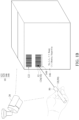
FIG. 1B is a schematic diagram of an application scenario of a barcode image recognition device according to the example ofFIG. 1A . -
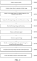
FIG. 2 is a flowchart of a barcode image recognition method according to some examples. -
FIG. 3 is a schematic diagram of a default image in step S 110 ofFIG. 2 . -
FIG. 4 is a functional block diagram of an example of a conversion module according to the example ofFIG. 1A . -
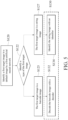
FIG. 5 is a flowchart of a barcode image recognition method according to some examples afterstep S 120 inFIG. 2 . -
FIG. 6A is a schematic diagram of an application scenario of a barcode image recognition device according to another example. -
FIG. 6B is a functional block diagram of a barcode image recognition device inFIG. 6A . -
FIG. 7 is a schematic diagram of an example of a barcode image recognition device inFIG. 6B . -
FIG. 8 is a schematic diagram of another example of a barcode image recognition device ofFIG. 6B . -
FIG. 9 is a flowchart of a barcode image recognition method according to some examples beforestep S 150 inFIG. 2 . -
FIG. 10 is a schematic diagram of an example of a barcode image recognition device inFIG. 6B . - Referring to
FIG. 1A , a barcode image recognition device includes acamera module 20, aninput component 30, aprocessing module 40, astorage module 60, anoutput module 70, and adisplay 80. Theinput component 30 and theprocessing module 40 are each coupled to thecamera module 20. Thestorage module 60 is coupled to theprocessing module 40. Theoutput module 70 is coupled to both theprocessing module 40 and thestorage module 60. Thedisplay 80 is coupled to theoutput module 70. - The
processing module 40 includes a first artificialneural network 42, aconversion module 44, a second artificialneural network 46, and acomparison module 48. The first artificialneural network 42 receives images captured by thecamera module 20. Theconversion module 44 is coupled to the first artificialneural network 42 and processes the images captured by thecamera module 20. The second artificialneural network 46 also receives the images captured by thecamera module 20, and thecomparison module 48 is coupled to the first artificialneural network 42 and the second artificialneural network 46 and also processes the aforementioned images. - Referring to
FIG. 1B andFIG. 2 , when the barcode image recognition device is used, the camera module 20 (step S 100) is enabled, and thecamera module 20 will continuously capture target objects 10 in advance to obtain a plurality ofdefault images 22 with continuous capturing time (step S110). In some examples, the target objects 10 arebarcodes strings - Referring to
FIG. 1B ,FIG. 2 andFIG. 3 together, thedefault image 22 may be similar to a picture a user previews and captures in real time through a screen when capturing with an electronic device. Thedefault image 22 has afirst target image 220 of eachtarget object 10. Taking thetarget object 10 having thebarcode 124 and thestring 146 as an example, thedefault image 22 will include abarcode image 224 of thebarcode 122 and astring image 226 of thestring 146. Thebarcode image 224 and thestring image 226 are obtained by the first artificialneural network 42 in theprocessing module 40 identifying the default image 22 (step S120). - The
processing module 40, after capturing these identifiedfirst target images 220, converts eachfirst target image 220 tostrings 450 and 452 (seeFIG. 7 orFIG. 8 ) with the conversion module 44 (step S130). - Referring to
FIG. 4 , in some examples, theconversion module 44 may be adecoder 440. When thefirst target image 220 is converted to thestring 450, thedecoder 440 decodes thebarcodes barcodes - In some other examples, the
conversion module 44 may be anidentifier 442. When thefirst target image 220 is converted to thestring 452, theidentifier 442 performs text identification on thestrings string image 226 as thestring 452. - Referring to
FIG. 4 andFIG. 5 , in some further examples, in a case where theconversion module 44 includes both thedecoder 440 and theidentifier 442, the first artificialneural network 42 can identify a type of the first target image 220 (the type is the above-mentionedbarcode image 224 or string image 226). - In detail, after the first artificial
neural network 42 identifies thefirst target image 220 in the default image 22 (step S120), the first artificialneural network 42 further identifies eachfirst target image 220 as thebarcode image 224 or string image 226 (step S122). If the first artificialneural network 42 identifies thefirst target image 220 as the barcode image 224 (step S125), thedecoder 440 in theconversion module 44 decodes thebarcode image 224 into the string 450 (step S132). If the first artificialneural network 42 identifies thefirst target image 220 as the string image 226 (step S127), theidentifier 442 in theconversion module 44 performs text identification on thestring image 226 to obtain the string 452 (step S134). - Referring back to
FIG. 2 , thestorage module 60 stores each of the above-mentionedfirst target images 220 and thestrings first target images 220 converted by the conversion module 44 (step S140). In some examples, a database ofbarcodes strings first target images 220 and thecorresponding strings default images 22 are stored, so that thestrings barcodes strings - Referring back to
FIG. 1B , when the user desires to obtain information about aparticular target object 10, theparticular target object 10 may be directly indicated by an indicatingdevice 50 or a finger, and then apredetermined mark 52 overlapping thetarget object 10 may be generated on thetarget object 10, and the indicatedtarget object 10 is taken as a selectedtarget object 16. In some examples, the indicatingdevice 50 is an infrared pen or a laser pen, and the generatedpredetermined mark 52 is a cursor. In some examples, the indicatingdevice 50 can be implemented with the finger, and thepredetermined mark 52 is a part where the finger points to thetarget object 10. - Referring to
FIG. 1B ,FIG. 2 ,FIG. 7 andFIG. 8 , after the user indicates thetarget object 10 with the indicatingdevice 50 or finger, thecamera module 20 takes a photo of the selectedtarget object 16 according to a confirmation signal (step S150) to obtain a captured image 24 (step S160). Here, the second artificialneural network 46 identifies the capturedimage 24 to obtain asecond target image 26 of the selected target object 16 (step S170). Thesecond target image 26 is thefirst target image 220 overlapping withmarked images predetermined mark 52. Subsequently, thecomparison module 48 compares thesecond target image 26 and each previously stored first target image 220 (step S180), and thefirst target image 220 with the highest similarity to thesecond target image 26 is used as a finalselected image 480. Theoutput module 70 extracts thestrings first target image 220 as the final selected image 480) from thestorage module 60, and thestrings - In this way, the user can quickly and easily select the
strings barcodes strings barcodes strings strings barcodes strings strings barcodes string 148. - Taking the indicating
device 50 as the infrared pen or the laser pen as an example, after the user presses a switch of the infrared pen or laser pen, the infrared pen or the laser pen generates a cursor, and themarked image 240 of the cursor (i.e., the predetermined mark 52) also begins to appear in thedefault image 22 captured by thecamera module 20 that performs capturing continuously. Taking the finger as the indicatingdevice 50 as an example, when the finger of the user enters the capturing range of thecamera module 20, themarked image 240 of the finger also begins to appear in thedefault image 22 captured by thecamera module 20. - Referring to
FIG. 6B andFIG. 9 , in some examples, theprocessing module 40 includes amark confirmation module 49. Themark confirmation module 49 is coupled to thecamera module 20. Themark confirmation module 49 identifies thedefault image 22 repeatedly captured by thecamera module 20 to confirm whether there are themarked images marked images default image 22, the position of themarked image 240 in thedefault image 22 is identified (step S150b), thereby knowing whether themarked image 240 overlaps with thefirst target image 220 or not. When themarked image 240 overlaps with thefirst target image 220 and the overlapping time reaches a predetermined time (step S 150c), theprocessing module 40 generates a confirmation signal and sends the same back to thecamera module 20. After thecamera module 20 detects the confirmation signal (step S150), a single capture is taken again to obtain the capturedimage 24 with the second target image 26 (step S160). - The intention of generating the confirmation signal after the
marked image first target images 220 for the predetermined time is that thepredetermined mark 52 cannot accurately point to the particular target object 10 from the beginning. Taking the indicatingdevice 50 as an infrared pen or a laser pen as an example, the user often cannot directly place the cursor on the particular target object 10 at the moment of pressing the switch, but needs to move the position of the cursor from the moment of pressing the switch onto the particular target object 10 (i.e., the selected target object 16). In an example where the finger is used as the indicatingdevice 50, there is also a similar situation where the finger cannot point to the particular target object 10 at the moment it appears in thedefault image 22. - During the movement of the cursor or finger, it may pass by other target objects 10 other than the selected
target object 16, and the overlapping time between the finger and the other target objects 10 during the movement will be shorter. Therefore, it can be judged whether the cursor or finger is indeed resting on the selectedtarget object 16 at present or not by "whether overlapping lasts for a predetermined time or not" (step S150c). - In some examples, if the
mark confirmation module 49 identifies that there are nomarked images default image 22 or that there are themarked images default image 22, but the overlapping time between themarked images first target image 220 does not exceed the predetermined time, it indicates that the predetermined mark 52 (finger or cursor) has not yet accurately indicated the selectedtarget object 16, and there is no need to make thecamera module 20 perform a single capture with the confirmation signal to obtain the capturedimage 24. At this time, themark confirmation module 49 can repeatedly judge thedefault image 22, and generate the confirmation signal when thedefault image 22 has the markedimages marked images first target image 220 and overlap for a predetermined time. - Referring back to
FIG. 1B , in some examples, the user generates the confirmation signal through theinput component 30, and theinput component 30 is a key 32. The key 32 can be implemented directly by the switch of the infrared pen or the laser pen. After the key 32 is pressed, the infrared pen or the laser pen generates a cursor, and thecamera module 20 also starts capturing. When themark confirmation module 49 identifies that thedefault image 22 captured by thecamera module 20 has the markedimage 240, and themarked image 240 overlaps with thefirst target image 220 and overlaps for a predetermined time, a confirmation signal is generated. Thecamera module 20 generates the capturedimage 24 with thesecond target image 26 after detecting the confirmation signal. - In some examples, the
input component 30 implemented with the key 32 is the key 32 independent of the switch of the infrared pen or the laser pen, then when the finger does overlap with the selectedtarget object 16, the user can press the key 32. Thecamera module 20 takes the single capture according to the confirmation signal generated when the user presses the key 32 to obtain the capturedimage 24 with thesecond target image 26. - Referring to
FIG. 2 orFIG. 7 andFIG. 8 , in some examples, after confirmation of the finalselected image 480, theoutput module 70 extracts thestrings decoder 440 or text identification by theidentifier 442, and thestrings display 80. Display fields 82 of thestrings display 80, and thestrings target object 10. - In some examples, the design of the fields in the
display 80 can be adjusted according to the user's needs. For example, on thedisplay 80, thedefault image 22 and thedisplay field 82, the capturedimage 24 and the display field 82 (as shown inFIG. 7 andFIG. 8 ), or thesecond target image 26, the finalselected image 480 and thedisplay field 82 can be displayed side by side in the picture of thedisplay 80. In some examples, thedisplay field 82 can be presented in a window. The window pops up after theprocessing module 40 judges the finalselected image 480, and displays thestrings selected image 480. - Referring to
FIG. 6A ,FIG. 7 andFIG. 8 , andFIG. 10 , in some other examples, when theinput component 30 is implemented with the key 32, the key 32 and thecamera module 20 are located together on a portableelectronic device 90. In some examples, the key 32 may be any button on the portableelectronic device 90 or a button on a user interface of the portableelectronic device 90. Thecamera module 20 may be a front lens or rear lens mounted on the portableelectronic device 90. - In some examples, the
camera module 20, theprocessing module 40, thestorage module 60, theoutput module 70, and thedisplay 80 can also be implemented with components of the portableelectronic device 90 itself. For example, theprocessing module 40 and theoutput module 70 may be implemented with theprocessor 92 of the portableelectronic device 90 itself. An internal memory in theprocessor 92 or an external memory of the portableelectronic device 90 may be used as thestorage module 60. Thedisplay 80 is implemented with a display screen of the portableelectronic device 90. The indicatingdevice 50 can also be provided on the portableelectronic device 90. - In some other examples, the
camera module 20, theprocessing module 40, thestorage module 60, theoutput module 70, and thedisplay 80 can also be independent of each other. For example, thecamera module 20 is an external camera that can be connected through a USB port, a Type C port or the like. Theprocessing module 40 is theprocessor 92 in the electronic device. Thestorage module 60 is an external hard disk. Thedisplay 80 is an external screen. - In some further examples, some of the
camera module 20, theprocessing module 40, thestorage module 60, theoutput module 70, and thedisplay 80 can be implemented by the components of the portableelectronic device 90 itself, and some of them are independent devices independent of the portableelectronic device 90. - In some examples, the portable
electronic device 90 may be apparatus such as a smartphone, a laptop and a tablet computer. - In some examples, the
processing module 40 can be implemented by one ormore processors 92. Each processor may be, but is not limited to, a central processing unit, a system on chip (SOC), a general-purpose or special-purpose microprocessor, a digital signal processor (DSP), a programmable logic controller (PLC), an application specific integrated circuit (ASIC), a programmable logic device (PLD), other similar processing devices, or a combination thereof. - In some examples, in addition to being implemented with the screen without a touch function of the above-mentioned portable
electronic device 90, thedisplay 80 may be, but is not limited to, a touch screen or a general external display screen (i.e., it has no touch function). The plurality ofdefault images 22 with the continuous capturing time captured by thecamera module 20 in advance can be presented in real-time in thedisplay 80. When thedisplay 80 is a touch screen, theinput component 30 may be thedisplay 80, or may be an input device additionally provided such as a keyboard, one or more keys, a writing tablet, or any combination thereof. - In some examples, the
identifier 442 identifies thestrings identifier 442 may be implemented with data marking and supervised learning, a template matching method, and a method of support vector machine (SVM) or decision tree in a machine learning model. - In some examples, the
comparison module 48 obtains the finalselected image 480 by using a method for comparing image similarities between thesecond target image 26 and eachfirst target image 220. The method for comparing the image similarities may be mean squared error (MSE), structural similarity index (SSIM), histogram comparison, and feature point comparison and the like. The other parts of thesecond target image 26 should be the same as one of the plurality offirst target images 220 stored, except for the part ofsecond target image 26 that overlaps with thepredetermined mark 52 or finger. - In some examples, the barcode image recognition device is used for managing goods in warehouses or logistics. There are one or
more barcodes strings barcodes strings barcodes strings barcodes strings - In some examples, the
barcodes barcodes barcodes dimensional barcodes string 450 of tens of characters, and the two-dimensional barcode may represent thestring 450 of thousands of characters. - In some examples, the
strings strings strings - In summary, in some examples, the barcode image recognition method and device can accurately and controllably output the information carried by the indicated
barcodes strings display 80 after being converted when there are a plurality ofbarcodes strings
Claims (15)
- A barcode image recognition method, comprising:enabling a camera module (20);continuously capturing, by the camera module (20), at least one target object (10) in advance after the camera module (20) is enabled to obtain a plurality of default images (22) with continuous capturing time;identifying, by a first artificial neural network (42), a first target image (220) of each target object (10) in each default image (22);capturing each first target image (220) from each default image (22);converting each first target image (220) into a string (450, 452);storing each first target image (220) and the string (450, 452) corresponding to each first target image (220);triggering the camera module (20) according to a confirmation signal to take a single capture of a predetermined mark (52) to obtain a captured image (24);identifying, by a second artificial neural network (46), a marked image (240, 242) of the predetermined mark (52) in the captured image (24) and a second target image (26) of a selected target object (16) of the at least one target object (10) that overlaps with the predetermined mark (52);comparing the second target image (26) with each first target image (220) to obtain a final selected image (480), the final selected image (480) being the first target image (220) with the highest similarity to the second target image (26); andreading the string (450, 452) corresponding to the final selected image (480) from the stored string (450, 452) and outputting the string (450, 452).
- The barcode image recognition method according to claim 1, wherein a type of the first target image (220) is a barcode image (224), and the step of converting each first target image (220) to the string (450, 452) comprises: decoding the first target image (220) into the string (450), wherein the string (450) is information carried by the first target image (220).
- The barcode image recognition method according to claim 1, wherein a type of the first target image (220) is a string image (226), and the step of converting each first target image (220) to the string (450, 452) comprises: performing text identification on the first target image (220) to obtain the string (452).
- The barcode image recognition method according to claim 1, further comprising:receiving the confirmation signal from an input component (30), wherein the input component (30) is a key (32), the key (32) is located on an indicating device (50) and the indicating device (50) is independent of the camera module (20); andgenerating, by the indicating device (50), the predetermined mark (52) on one of the at least one target object (10).
- The barcode image recognition method according to claim 1, further comprising:receiving the confirmation signal from an input component (30), wherein the input component (30) is a key (32), the key (32) and the camera module (20) are located on a portable electronic device (90); andgenerating, by the portable electronic device (90), the predetermined mark (52) on one of the at least one target object (10), wherein the predetermined mark (52) is a cursor.
- The barcode image recognition method according to claim 1, further comprising:identifying the marked image (240, 242) of the predetermined mark (52) in each default image (22) to obtain a marked position of the marked image (240, 242) in each default image (22); andgenerating the confirmation signal according to the capturing time of the default images (22) with the marked image (240, 242) in these default images (22) and the marked position.
- The barcode image recognition method according to claim 6, further comprising:
pointing to, by an indicating device (50), the selected target object (16) in the at least one target object (10) to form the predetermined mark (52) overlapping with the selected target object (16). - The barcode image recognition method according to claim 1, further comprising:
providing that the predetermined mark (52) overlaps with the selected target object (16) in the at least one target object (10). - A barcode image recognition device, comprising:a camera module (20), configured to continuously capture at least one target object (10) in advance to obtain a plurality of default images (22) with continuous capturing time;an input component (30), coupled to the camera module (20), and configured to generate a confirmation signal to trigger the camera module (20) to take a single capture of a predetermined mark (52) to obtain a captured image (24) where the predetermined mark (52) overlaps with the at least one target object (10);a processing module (40), coupled to the camera module (20), comprising:a first artificial neural network (42), identifying a first target image (220) of each target object (10) in each default image (22);a conversion module (44), converting each first target image (220) to a string (450, 452);a second artificial neural network (46), identifying a marked image (240, 242) of the predetermined mark (52) in the captured image (24) and a second target image (26) of a selected target object (16) of the at least one target object (10) that overlaps with the predetermined mark (52); anda comparison module (48), coupled to the first artificial neural network (42) and the second artificial neural network (46), and comparing the second target image (26) with each first target image (220) to obtain a final selected image (480), the final selected image (480) being the first target image (220) with the highest similarity to the second target image (26);a storage module (60), coupled to the processing module (40), and storing each first target image (220) and the string (450, 452) corresponding to each first target image (220);an output module (70), coupled to the comparison module (48) and the storage module (60), and reading the string (450, 452) corresponding to the final selected image (480) from the storage module (60); anda display (80), coupled to the output module (70), and displaying the string (450, 452) read by the output module (70).
- The barcode image recognition device according to claim 9, wherein the conversion module (44) comprises a decoder (440), and the decoder (440) decodes the first target image (220) into the string (450).
- The barcode image recognition device according to claim 9, wherein the conversion module (44) comprises an identifier (442), and the identifier (442) performs text identification on the first target image (220) to obtain the string (452).
- The barcode image recognition device according to claim 9, further comprising an indicating device (50), the input component (30) is a key (32), the key (32) being located on the indicating device (50), and the indicating device (50) being independent of the camera module (20), the indicating device (50) generating the predetermined mark (52) on one of the at least one target object (10).
- The barcode image recognition device according to claim 9, wherein the input component (30) is a key (32), the key (32) and the camera module (20) are located on a portable electronic device (90), wherein the portable electronic device (90) generates the predetermined mark (52) on one of the at least one target object (10).
- The barcode image recognition device according to claim 9, wherein the predetermined mark (52) is a finger, a cursor generated by an infrared pen, or a cursor generated by a laser pen.
- The barcode image recognition device according to claim 9, wherein the processing module (40) further comprises a mark confirmation module (49), configured to identify the marked image (240, 242) of the predetermined mark (52) in each default image (22) to obtain a marked position of the marked image (240, 242) in each default image (22), and generate the confirmation signal according to the capturing time of the plurality of default images (22) with the marked image (240, 242) in these default images (22) and the marked position.
Applications Claiming Priority (1)
| Application Number | Priority Date | Filing Date | Title |
|---|---|---|---|
| CN202311123571.XA CN119558333A (en) | 2023-09-01 | 2023-09-01 | Barcode image recognition method and device |
Publications (1)
| Publication Number | Publication Date |
|---|---|
| EP4517679A1 true EP4517679A1 (en) | 2025-03-05 |
Family
ID=88837333
Family Applications (1)
| Application Number | Title | Priority Date | Filing Date |
|---|---|---|---|
| EP23210044.6A Pending EP4517679A1 (en) | 2023-09-01 | 2023-11-15 | Barcode image recognition method and device using the same |
Country Status (4)
| Country | Link |
|---|---|
| US (1) | US20250077816A1 (en) |
| EP (1) | EP4517679A1 (en) |
| CN (1) | CN119558333A (en) |
| AU (1) | AU2023274111B1 (en) |
Citations (1)
| Publication number | Priority date | Publication date | Assignee | Title |
|---|---|---|---|---|
| US11328147B1 (en) * | 2019-06-27 | 2022-05-10 | Amazon Technologies, Inc. | Identifying item barcodes |
Family Cites Families (3)
| Publication number | Priority date | Publication date | Assignee | Title |
|---|---|---|---|---|
| US7156310B2 (en) * | 1990-09-17 | 2007-01-02 | Metrologic Instruments, Inc. | Automatically-activated hand-supportable laser scanning bar code symbol reading system with data transmission activation switch |
| KR102157313B1 (en) * | 2013-09-03 | 2020-10-23 | 삼성전자주식회사 | Method and computer readable recording medium for recognizing an object using a captured image |
| US11995899B2 (en) * | 2021-04-29 | 2024-05-28 | Google Llc | Pointer-based content recognition using a head-mounted device |
-
2023
- 2023-09-01 CN CN202311123571.XA patent/CN119558333A/en active Pending
- 2023-10-24 US US18/383,075 patent/US20250077816A1/en active Pending
- 2023-11-15 EP EP23210044.6A patent/EP4517679A1/en active Pending
- 2023-11-28 AU AU2023274111A patent/AU2023274111B1/en active Active
Patent Citations (1)
| Publication number | Priority date | Publication date | Assignee | Title |
|---|---|---|---|---|
| US11328147B1 (en) * | 2019-06-27 | 2022-05-10 | Amazon Technologies, Inc. | Identifying item barcodes |
Non-Patent Citations (1)
| Title |
|---|
| LING CHEN: "On Scanning Linear Barcodes From Out-of-Focus Blurred Images: A Spatial Domain Dynamic Template Matching Approach", vol. 23, no. 6, 1 June 2014 (2014-06-01), USA, pages 2637 - 2650, XP093155955, ISSN: 1057-7149, Retrieved from the Internet <URL:https://ieeexplore.ieee.org/stampPDF/getPDF.jsp?tp=&arnumber=6804660&ref=aHR0cHM6Ly93d3cuZ29vZ2xlLmNvbS8=> [retrieved on 20240425], DOI: 10.1109/TIP.2014.2319579 * |
Also Published As
| Publication number | Publication date |
|---|---|
| US20250077816A1 (en) | 2025-03-06 |
| AU2023274111B1 (en) | 2025-03-20 |
| CN119558333A (en) | 2025-03-04 |
Similar Documents
| Publication | Publication Date | Title |
|---|---|---|
| US20230067071A1 (en) | System and method for document processing | |
| US9027833B2 (en) | Commodity information display apparatus and method for displaying commodity information in different forms | |
| CN111723640B (en) | Product information inspection system and computer control method | |
| JP2004127013A (en) | Point of sale information management device | |
| CN105448001A (en) | Commodity registration device | |
| USRE50445E1 (en) | Method for scanning multiple barcodes and system thereof | |
| EP2320350B1 (en) | Annotation of optical images on a mobile device | |
| JP6651169B2 (en) | Display status judgment system | |
| CN101515392B (en) | Data code reader and data code reading method | |
| US20150063639A1 (en) | Commodity registration apparatus and commodity registration method | |
| US12039398B1 (en) | Barcode-aware object verification using image encoder | |
| US20160171581A1 (en) | Apparatus and method for locating products in a retail store using a mobile device | |
| CN112550886A (en) | Inspection device and label sticking device | |
| JP6885563B2 (en) | Display status judgment system | |
| US20150063638A1 (en) | Commodity registration apparatus and commodity registration method | |
| JP6670511B2 (en) | Product information acquisition system | |
| US20250077816A1 (en) | Barcode image recognition method and device using the same | |
| US9355395B2 (en) | POS terminal apparatus and commodity specification method | |
| TWI858898B (en) | Barcode image recogniztion method and device using the same | |
| JP2019128826A (en) | Article recognition device and commodity settlement device | |
| WO2019181441A1 (en) | Information processing device, control method, program | |
| CN118586411A (en) | Barcode image recognition method and device | |
| US20180173481A1 (en) | Information processing apparatus, program, printing apparatus, and printing system | |
| JP7160086B2 (en) | Information processing device, control method, and program | |
| US20240020995A1 (en) | Systems and methods for automated extraction of target text strings |
Legal Events
| Date | Code | Title | Description |
|---|---|---|---|
| PUAI | Public reference made under article 153(3) epc to a published international application that has entered the european phase |
Free format text: ORIGINAL CODE: 0009012 |
|
| STAA | Information on the status of an ep patent application or granted ep patent |
Free format text: STATUS: REQUEST FOR EXAMINATION WAS MADE |
|
| 17P | Request for examination filed |
Effective date: 20240828 |
|
| AK | Designated contracting states |
Kind code of ref document: A1 Designated state(s): AL AT BE BG CH CY CZ DE DK EE ES FI FR GB GR HR HU IE IS IT LI LT LU LV MC ME MK MT NL NO PL PT RO RS SE SI SK SM TR |
|
| STAA | Information on the status of an ep patent application or granted ep patent |
Free format text: STATUS: EXAMINATION IS IN PROGRESS |
|
| 17Q | First examination report despatched |
Effective date: 20260324 |