EP4517580A1 - Identification mark recognition device, identification mark recognition method, and secondary battery manufacturing method - Google Patents
Identification mark recognition device, identification mark recognition method, and secondary battery manufacturing method Download PDFInfo
- Publication number
- EP4517580A1 EP4517580A1 EP24750563.9A EP24750563A EP4517580A1 EP 4517580 A1 EP4517580 A1 EP 4517580A1 EP 24750563 A EP24750563 A EP 24750563A EP 4517580 A1 EP4517580 A1 EP 4517580A1
- Authority
- EP
- European Patent Office
- Prior art keywords
- identification mark
- electrode tab
- electrode
- pressing
- unit
- Prior art date
- Legal status (The legal status is an assumption and is not a legal conclusion. Google has not performed a legal analysis and makes no representation as to the accuracy of the status listed.)
- Pending
Links
Images









Classifications
-
- H—ELECTRICITY
- H01—ELECTRIC ELEMENTS
- H01M—PROCESSES OR MEANS, e.g. BATTERIES, FOR THE DIRECT CONVERSION OF CHEMICAL ENERGY INTO ELECTRICAL ENERGY
- H01M10/00—Secondary cells; Manufacture thereof
- H01M10/04—Construction or manufacture in general
- H01M10/0431—Cells with wound or folded electrodes
-
- H—ELECTRICITY
- H01—ELECTRIC ELEMENTS
- H01M—PROCESSES OR MEANS, e.g. BATTERIES, FOR THE DIRECT CONVERSION OF CHEMICAL ENERGY INTO ELECTRICAL ENERGY
- H01M50/00—Constructional details or processes of manufacture of the non-active parts of electrochemical cells other than fuel cells, e.g. hybrid cells
- H01M50/50—Current conducting connections for cells or batteries
- H01M50/572—Means for preventing undesired use or discharge
- H01M50/598—Guarantee labels
-
- G—PHYSICS
- G06—COMPUTING OR CALCULATING; COUNTING
- G06K—GRAPHICAL DATA READING; PRESENTATION OF DATA; RECORD CARRIERS; HANDLING RECORD CARRIERS
- G06K19/00—Record carriers for use with machines and with at least a part designed to carry digital markings
- G06K19/06—Record carriers for use with machines and with at least a part designed to carry digital markings characterised by the kind of the digital marking, e.g. shape, nature, code
- G06K19/06009—Record carriers for use with machines and with at least a part designed to carry digital markings characterised by the kind of the digital marking, e.g. shape, nature, code with optically detectable marking
- G06K19/06018—Record carriers for use with machines and with at least a part designed to carry digital markings characterised by the kind of the digital marking, e.g. shape, nature, code with optically detectable marking one-dimensional coding
- G06K19/06028—Record carriers for use with machines and with at least a part designed to carry digital markings characterised by the kind of the digital marking, e.g. shape, nature, code with optically detectable marking one-dimensional coding using bar codes
-
- G—PHYSICS
- G06—COMPUTING OR CALCULATING; COUNTING
- G06K—GRAPHICAL DATA READING; PRESENTATION OF DATA; RECORD CARRIERS; HANDLING RECORD CARRIERS
- G06K19/00—Record carriers for use with machines and with at least a part designed to carry digital markings
- G06K19/06—Record carriers for use with machines and with at least a part designed to carry digital markings characterised by the kind of the digital marking, e.g. shape, nature, code
- G06K19/06009—Record carriers for use with machines and with at least a part designed to carry digital markings characterised by the kind of the digital marking, e.g. shape, nature, code with optically detectable marking
- G06K19/06037—Record carriers for use with machines and with at least a part designed to carry digital markings characterised by the kind of the digital marking, e.g. shape, nature, code with optically detectable marking multi-dimensional coding
-
- G—PHYSICS
- G06—COMPUTING OR CALCULATING; COUNTING
- G06K—GRAPHICAL DATA READING; PRESENTATION OF DATA; RECORD CARRIERS; HANDLING RECORD CARRIERS
- G06K7/00—Methods or arrangements for sensing record carriers, e.g. for reading patterns
- G06K7/10—Methods or arrangements for sensing record carriers, e.g. for reading patterns by electromagnetic radiation, e.g. optical sensing; by corpuscular radiation
- G06K7/10544—Methods or arrangements for sensing record carriers, e.g. for reading patterns by electromagnetic radiation, e.g. optical sensing; by corpuscular radiation by scanning of the records by radiation in the optical part of the electromagnetic spectrum
- G06K7/10821—Methods or arrangements for sensing record carriers, e.g. for reading patterns by electromagnetic radiation, e.g. optical sensing; by corpuscular radiation by scanning of the records by radiation in the optical part of the electromagnetic spectrum further details of bar or optical code scanning devices
-
- G—PHYSICS
- G06—COMPUTING OR CALCULATING; COUNTING
- G06K—GRAPHICAL DATA READING; PRESENTATION OF DATA; RECORD CARRIERS; HANDLING RECORD CARRIERS
- G06K7/00—Methods or arrangements for sensing record carriers, e.g. for reading patterns
- G06K7/10—Methods or arrangements for sensing record carriers, e.g. for reading patterns by electromagnetic radiation, e.g. optical sensing; by corpuscular radiation
- G06K7/10544—Methods or arrangements for sensing record carriers, e.g. for reading patterns by electromagnetic radiation, e.g. optical sensing; by corpuscular radiation by scanning of the records by radiation in the optical part of the electromagnetic spectrum
- G06K7/10821—Methods or arrangements for sensing record carriers, e.g. for reading patterns by electromagnetic radiation, e.g. optical sensing; by corpuscular radiation by scanning of the records by radiation in the optical part of the electromagnetic spectrum further details of bar or optical code scanning devices
- G06K7/10861—Methods or arrangements for sensing record carriers, e.g. for reading patterns by electromagnetic radiation, e.g. optical sensing; by corpuscular radiation by scanning of the records by radiation in the optical part of the electromagnetic spectrum further details of bar or optical code scanning devices sensing of data fields affixed to objects or articles, e.g. coded labels
-
- G—PHYSICS
- G06—COMPUTING OR CALCULATING; COUNTING
- G06K—GRAPHICAL DATA READING; PRESENTATION OF DATA; RECORD CARRIERS; HANDLING RECORD CARRIERS
- G06K7/00—Methods or arrangements for sensing record carriers, e.g. for reading patterns
- G06K7/10—Methods or arrangements for sensing record carriers, e.g. for reading patterns by electromagnetic radiation, e.g. optical sensing; by corpuscular radiation
- G06K7/14—Methods or arrangements for sensing record carriers, e.g. for reading patterns by electromagnetic radiation, e.g. optical sensing; by corpuscular radiation using light without selection of wavelength, e.g. sensing reflected white light
- G06K7/1404—Methods for optical code recognition
- G06K7/1408—Methods for optical code recognition the method being specifically adapted for the type of code
- G06K7/1413—1D bar codes
-
- G—PHYSICS
- G06—COMPUTING OR CALCULATING; COUNTING
- G06K—GRAPHICAL DATA READING; PRESENTATION OF DATA; RECORD CARRIERS; HANDLING RECORD CARRIERS
- G06K7/00—Methods or arrangements for sensing record carriers, e.g. for reading patterns
- G06K7/10—Methods or arrangements for sensing record carriers, e.g. for reading patterns by electromagnetic radiation, e.g. optical sensing; by corpuscular radiation
- G06K7/14—Methods or arrangements for sensing record carriers, e.g. for reading patterns by electromagnetic radiation, e.g. optical sensing; by corpuscular radiation using light without selection of wavelength, e.g. sensing reflected white light
- G06K7/1404—Methods for optical code recognition
- G06K7/1408—Methods for optical code recognition the method being specifically adapted for the type of code
- G06K7/1417—2D bar codes
-
- H—ELECTRICITY
- H01—ELECTRIC ELEMENTS
- H01M—PROCESSES OR MEANS, e.g. BATTERIES, FOR THE DIRECT CONVERSION OF CHEMICAL ENERGY INTO ELECTRICAL ENERGY
- H01M10/00—Secondary cells; Manufacture thereof
- H01M10/04—Construction or manufacture in general
-
- H—ELECTRICITY
- H01—ELECTRIC ELEMENTS
- H01M—PROCESSES OR MEANS, e.g. BATTERIES, FOR THE DIRECT CONVERSION OF CHEMICAL ENERGY INTO ELECTRICAL ENERGY
- H01M10/00—Secondary cells; Manufacture thereof
- H01M10/04—Construction or manufacture in general
- H01M10/0404—Machines for assembling batteries
- H01M10/0409—Machines for assembling batteries for cells with wound electrodes
-
- H—ELECTRICITY
- H01—ELECTRIC ELEMENTS
- H01M—PROCESSES OR MEANS, e.g. BATTERIES, FOR THE DIRECT CONVERSION OF CHEMICAL ENERGY INTO ELECTRICAL ENERGY
- H01M10/00—Secondary cells; Manufacture thereof
- H01M10/04—Construction or manufacture in general
- H01M10/0481—Compression means other than compression means for stacks of electrodes and separators
-
- H—ELECTRICITY
- H01—ELECTRIC ELEMENTS
- H01M—PROCESSES OR MEANS, e.g. BATTERIES, FOR THE DIRECT CONVERSION OF CHEMICAL ENERGY INTO ELECTRICAL ENERGY
- H01M50/00—Constructional details or processes of manufacture of the non-active parts of electrochemical cells other than fuel cells, e.g. hybrid cells
- H01M50/50—Current conducting connections for cells or batteries
- H01M50/531—Electrode connections inside a battery casing
-
- H—ELECTRICITY
- H01—ELECTRIC ELEMENTS
- H01M—PROCESSES OR MEANS, e.g. BATTERIES, FOR THE DIRECT CONVERSION OF CHEMICAL ENERGY INTO ELECTRICAL ENERGY
- H01M50/00—Constructional details or processes of manufacture of the non-active parts of electrochemical cells other than fuel cells, e.g. hybrid cells
- H01M50/50—Current conducting connections for cells or batteries
- H01M50/531—Electrode connections inside a battery casing
- H01M50/538—Connection of several leads or tabs of wound or folded electrode stacks
-
- H—ELECTRICITY
- H01—ELECTRIC ELEMENTS
- H01M—PROCESSES OR MEANS, e.g. BATTERIES, FOR THE DIRECT CONVERSION OF CHEMICAL ENERGY INTO ELECTRICAL ENERGY
- H01M50/00—Constructional details or processes of manufacture of the non-active parts of electrochemical cells other than fuel cells, e.g. hybrid cells
- H01M50/50—Current conducting connections for cells or batteries
- H01M50/543—Terminals
- H01M50/552—Terminals characterised by their shape
- H01M50/553—Terminals adapted for prismatic, pouch or rectangular cells
- H01M50/557—Plate-shaped terminals
-
- Y—GENERAL TAGGING OF NEW TECHNOLOGICAL DEVELOPMENTS; GENERAL TAGGING OF CROSS-SECTIONAL TECHNOLOGIES SPANNING OVER SEVERAL SECTIONS OF THE IPC; TECHNICAL SUBJECTS COVERED BY FORMER USPC CROSS-REFERENCE ART COLLECTIONS [XRACs] AND DIGESTS
- Y02—TECHNOLOGIES OR APPLICATIONS FOR MITIGATION OR ADAPTATION AGAINST CLIMATE CHANGE
- Y02E—REDUCTION OF GREENHOUSE GAS [GHG] EMISSIONS, RELATED TO ENERGY GENERATION, TRANSMISSION OR DISTRIBUTION
- Y02E60/00—Enabling technologies; Technologies with a potential or indirect contribution to GHG emissions mitigation
- Y02E60/10—Energy storage using batteries
-
- Y—GENERAL TAGGING OF NEW TECHNOLOGICAL DEVELOPMENTS; GENERAL TAGGING OF CROSS-SECTIONAL TECHNOLOGIES SPANNING OVER SEVERAL SECTIONS OF THE IPC; TECHNICAL SUBJECTS COVERED BY FORMER USPC CROSS-REFERENCE ART COLLECTIONS [XRACs] AND DIGESTS
- Y02—TECHNOLOGIES OR APPLICATIONS FOR MITIGATION OR ADAPTATION AGAINST CLIMATE CHANGE
- Y02P—CLIMATE CHANGE MITIGATION TECHNOLOGIES IN THE PRODUCTION OR PROCESSING OF GOODS
- Y02P70/00—Climate change mitigation technologies in the production process for final industrial or consumer products
- Y02P70/50—Manufacturing or production processes characterised by the final manufactured product
Definitions
- the present invention relates to an identification mark recognition device and method for identifying an identification mark on an electrode tab.
- the present invention also relates to a secondary battery manufacturing method using the identification mark recognition device and method.
- the present invention relates to an identification mark recognition device for aligning an electrode tab with respect to an identification mark reader to improve a recognition rate of the identification mark reader, an identification mark recognition method, and a secondary battery manufacturing method.
- a secondary battery is manufactured by a number of sub-processes such as a process involving coating a current collector with an active material and rolling the current collector to manufacture positive electrodes and negative electrodes, a notching process involving forming electrode tabs, an electrode assembly manufacturing process for manufacturing an electrode assembly using the manufactured electrodes and separators, a packaging process for accommodating the electrode assembly in a case, and a charging/discharging process for providing characteristics before shipment.
- sub-processes such as a process involving coating a current collector with an active material and rolling the current collector to manufacture positive electrodes and negative electrodes, a notching process involving forming electrode tabs, an electrode assembly manufacturing process for manufacturing an electrode assembly using the manufactured electrodes and separators, a packaging process for accommodating the electrode assembly in a case, and a charging/discharging process for providing characteristics before shipment.
- An identification mark may be marked on electrode tabs of the electrodes (the positive and negative electrodes) to check and track an intermediate product during a manufacturing process.
- the identification mark on the electrode tab may be identified to specify the electrode.
- information about the identification mark may be connected with information about the sub-processes to track the sub-process into which the electrode is currently put.
- the electrode tabs are very thin and thus are likely to be bent or crumpled during the transfer of the electrodes.
- the lifting or crumpling of electrode tabs may become severe due to various factors, such as when the electrode tabs lean to one side or are pushed out.
- Patent Document 1 Chinese Patent Laid-Open Publication No. 113156528
- the present invention is directed to providing an identification mark recognition device for increasing a recognition rate of an identification mark reader by pressing electrode tabs to be aligned with respect to the identification mark reader, an identification mark recognition method, and a secondary battery manufacturing method.
- an identification mark recognition device includes: an identification mark reader configured to identify an identification mark on an electrode tab of a unit cell or an electrode assembly; an electrode tab pressing unit configured to press the electrode tab to cause a surface of the electrode tab on which the identification mark is marked to be aligned with respect to the identification mark reader; and a controller configured to control the electrode tab pressing unit and the identification mark reader to allow the identification mark reader to identify the identification mark after the pressing of the electrode tab by the electrode tab pressing unit, in which the electrode tab pressing unit is arranged to be inclined at a predetermined angle with respect to the unit cell or the electrode assembly.
- Outer surfaces of the plurality of pressing strings may be coated with fluorinated ethylene propylene (FEP) or poly tetrafluoro ethylene (PTFE).
- FEP fluorinated ethylene propylene
- PTFE poly tetrafluoro ethylene
- the plurality of pressing strings may be arranged to be parallel to a direction in which the electrode tab extends from a body part of the unit cell or a body part of the electrode assembly.
- the electrode tab pressing unit may include a main body frame with a through-hole, and a plurality of string brackets installed on the main body frame that protrude from the main body frame in the direction of pressing by the electrode tab pressing unit, the plurality of string brackets may be arranged to face each other with the through-hole interposed therebetween, and both ends of the plurality of pressing strings may be fixed on the plurality of string brackets facing each other.
- the identification mark reader may be slantingly arranged over the unit cell or the electrode assembly to be on the same axis as the through-hole.
- the identification mark may be bar-code or quick response (QR) code.
- the identification mark recognition device may further include a lighting member between the identification mark reader and the electrode tab, and the lighting member may be on the same axis as the identification mark reader.
- the identification mark recognition device may further include an air injector configured to inject air toward the electrode tab before the electrode tab is pressed by the electrode tab pressing unit.
- an identification mark recognition method includes: placing a unit cell or an electrode assembly, which includes an electrode tab on which an identification mark is marked, below an identification mark reader; moving an electrode tab pressing unit toward the electrode tab to press the electrode tab causing the electrode tab to be perpendicular to the identification mark reader; and identifying the identification mark on the electrode tab by the identification mark reader in a state in which the electrode tab is perpendicular to the identification mark reader.
- a secondary battery manufacturing method includes: preparing a plurality of unit cells including electrode tabs on which an identification mark is marked; manufacturing an electrode assembly by stacking the plurality of unit cells with a separator interposed therebetween or rolling up the plurality of unit cells placed on a separator sheet with the separator sheet; placing the electrode assembly below an identification mark reader; pressing the electrode tab of an uppermost unit cell of the electrode assembly to be perpendicular to the identification mark reader; and identifying the identification mark on the electrode tab with the identification mark reader in a state in which the electrode tab is perpendicular to the identification mark reader.
- the plurality of unit cells may be a half-cell, a mono-cell or a bi-cell.
- the electrode assembly may include unit cells of the same type or unit cells of different types.
- the secondary battery manufacturing method may further include identifying the electrode tabs of the unit cells with a separate identification mark reader before the manufacturing of the electrode assembly.
- An identification mark recognition device of the present invention may be placed in a transfer path of a unit cell or an electrode assembly.
- the traceability of an intermediate product of a battery cell can be more easily secured in an entire manufacturing process of the battery cell by effectively identifying an identification mark on electrode tabs.
- the identification mark may be marked on the electrode tabs in the form of bar-code, quick response (QR) code, or numbers.
- the identification mark may be printed on the electrode tabs using ink or the like or be engraved in or embossed on the electrode tabs.
- a form of the identification mark or a method of marking the identification mark on the electrode tabs is not particularly limited, as long as the identification mark can be marked on one surface of each of the electrode tabs and identified by an identification mark reader.
- the bi-cell may be manufactured by sequentially stacking a positive electrode, a separator, a negative electrode, a separator, and a positive electrode.
- the bi-cell may be manufactured by sequentially stacking a negative electrode, a separator, a positive electrode, a separator, and a negative electrode.
- an "electrode assembly” may be manufactured by stacking a plurality of unit cells with separators interposed therebetween.
- the electrode assembly may be manufactured by stacking a plurality of bi-cells on a separator and winding the separator.
- the electrode assembly 10 includes a plurality of electrode tabs T.
- An identification mark may be marked on each of the electrode tabs T.
- An identification mark reader may identify a identification mark I on an outermost electrode tab T' among the plurality of electrode tabs T. In this case, the identification mark I is exposed to the outside, making it easy for the identification mark reader to identify the identification mark I.
- the electrode tabs T may extend from a body part 11 of the electrode assembly 10 to both ends of the electrode assembly 10. However, the electrode tabs T may extend to one end of the body part 11 according to the design of the electrode assembly 10.
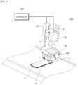
- FIG. 2 is a perspective view of an identification mark recognition device 1000 according to the present invention
- FIG. 3 is an exploded perspective view of the identification mark recognition device 1000.
- the identification mark recognition device 1000 includes an identification mark reader 100 that identifies an identification mark I on an electrode tab T of an electrode assembly 10, an electrode tab pressing unit 200 that presses the electrode tab T to be aligned, and a controller 300 that controls the identification mark reader 100 and the electrode tab pressing unit 200.
- the identification mark reader 100 may be provided over the electrode assembly 10.
- a mounting bracket M may be installed on the identification mark recognition device 1000 over the electrode assembly to be transferred, and the identification mark reader 100 may be coupled to the mounting bracket M.
- the identification mark reader 100 may be provided on an outermost electrode tab T among the electrode tabs T of the electrode assembly 10 to identify an identification mark I on an electrode tab T facing the identification mark reader 100 as a representative identification mark I of the electrode assembly 10.
- the mounting bracket M may be a general metal bracket with a predetermined thickness.
- a shape, material, etc. of the mounting bracket M are not particularly limited as long as the identification mark reader 100 can be fixed to an upper or lower part of a transfer path of the electrode assembly 10.
- the identification mark reader 100 may be connected to the controller 300 via wire or wirelessly.
- the identification mark reader 100 may identify the identification mark I by photographing the electrode tab T according to an operation signal from the controller 300.
- the identification mark reader 100 may transmit obtained information about the identified identification mark I to the controller 300.
- the electrode tab pressing unit 200 is arranged slantly at a predetermined angle with respect to a unit cell or the electrode assembly 10. As shown in FIG. 1 , the body part 11 of the electrode assembly 10 is thicker than a portion of the electrode assembly 10 from which the electrode tab T protrudes. This also applies to the unit cell. Accordingly, when the electrode tab pressing unit 200 presses the electrode tab T perpendicular to the electrode assembly 10, the electrode tab T is continuously pressed in contact with the body part 11, thus causing damage to the body part 11 (e.g., tearing of the separator, damage to an electrode active material, etc.). However, when the electrode tab pressing unit 200 is arranged slantly, a pressing surface of the electrode tab pressing unit 200 may be first brought into contact with the electrode tab T to minimize damage of the body part 11.
- the electrode tab pressing unit 200 when the electrode tab pressing unit 200 is excessively inclined, the electrode tab T may be severely deformed (warped or bent) when pressed by the electrode tab pressing unit 200. Accordingly, the above-described angle may be appropriately selected within a range that prevents the electrode tab T from being deformed (warped or bent) when pressed by the electrode tab pressing unit 200.
- an end of the electrode tab pressing unit 200 in a direction of pressing by the electrode tab pressing unit 200 may be provided with a plurality of pressing strings 230 for pressing the electrode tab T.
- the electrode tab pressing unit 200 may come into line contact with the electrode tab T by the pressing strings 230 when the electrode tab pressing unit 200 applies pressure. Therefore, a sufficient pressing force may be applied to the electrode tab T by employing the pressing strings 230 instead of other pressing members or alignment members configured to be in point contact with the electrode tab T. In addition, damage to the electrode tab T may be minimized by employing the pressing strings 230 instead of other pressing members or alignment members configured to be in surface contact with the electrode tab T.
- the pressing strings 330 should be appropriately disposed such that the identification mark I is not hidden in a field of view of the identification mark reader 100 when the electrode tab T is pressed by the electrode tab pressing unit 200. To this end, the pressing strings 330 are preferably disposed to press surfaces of the electrode tab T that are spaced a predetermined distance from both ends of the identification mark I.
- the number and arrangement of the pressing strings 330 may be appropriately selected such that the identification mark I is not hidden in the field of view of the identification mark reader 100.
- An outer surface of the pressing string 330 may be coated with fluorinated ethylene propylene (FEP) or poly tetrafluoro ethylene (PTFE).
- FEP fluorinated ethylene propylene
- PTFE poly tetrafluoro ethylene
- the electrode tab pressing unit 200 may include a main body frame 210 with a through-hole 211 and a string bracket 220 in which the pressing string 230 is installed.
- the main body frame 210 may have a rectangular frame shape.
- the present invention is not limited thereto, and a shape of the main body frame 210 may be appropriately selected as long as the string bracket 220 can be installed.
- the through-hole 211 may be provided in a central area of the main body frame 210 as shown in FIGS. 4 and 5 . Total weight of the main body frame 210 may be reduced by providing the through-hole 211 in the main body frame 210.
- the through-hole 211 extends in a height direction of the main body frame 210. That is, the main body frame 210 includes the through-hole 211 and thus may have a rectangular frame shape, the central part of which is empty. Therefore, even when the electrode tab T is pressed by the electrode tab pressing unit 200, the identification mark reader 100 may easily identify the identification mark I through the through-hole 211.
- the pressing string 230 may be installed on an inner wall of the through-hole 211.
- a conveyor that transfers the electrode assembly 10 may come into contact with an outer circumferential surface of the pressing string 230 and thus be damaged. Therefore, as shown in FIGS. 4 to 6 , a plurality of string brackets 220 are preferably installed on the main body frame 210 to protrude from the main body frame 210 in a direction in which the electrode tab T is pressed by the electrode tab pressing unit 200.
- the string brackets 220 may be disposed to face each other with the through-hole 211 interposed therebetween. In this case, both ends of the pressing string 230 are fixed to the string brackets 220 facing each other and thus the pressing string 230 may be located on an end of the electrode tab pressing unit 200 in the direction of pressing.
- An even number of string brackets 220 are preferably provided because the both ends of the pressing string 230 are fixed to the string brackets 220.
- a pair of string brackets 220 that are symmetrical to each other may be provided.
- the providing of the pair of string brackets 220 is only an example, and the number of string brackets 220 to be installed is not particularly limited as long as both ends of the pressing string 230 can be easily fixed.
- the string brackets 220 are disposed to be spaced a predetermined distance from each other with the through-hole 211 interposed therebetween.
- the string brackets 220 are also disposed slantly. Therefore, when the string brackets 220 are installed on the main body frame 210 to be excessively spaced apart from each other, the string brackets 220 may apply impact to transfer equipment (e.g., a conveyor) of the electrode assembly 10 when the electrode tab T is pressed. In this case, the transfer equipment may be damaged by the string brackets 220.
- transfer equipment e.g., a conveyor
- a distance between the string brackets 220 may be appropriately set to prevent the string brackets 220 from being in contact with the transfer equipment of the electrode assembly 10 when the electrode tab pressing unit 200 presses the electrode tab T.
- a length of the pressing strings 230 may be determined according to the distance between the string brackets 220.
- the string brackets 220 may be plates having a square shape with a predetermined thickness. A shape and thickness of the string brackets 220 may be appropriately changed according to the design of the string brackets 220 or the electrode tab pressing unit 200.
- the pressing string 230 may be coupled to the string bracket 220 by winding both ends of the pressing string 230 around bolts B and screwing the bolts B into screwing holes 221.
- the above coupling method is only one example, and other coupling methods may also be appropriately selected as long as the pressing string 230 can be fixed to the string bracket 220.
- the pressing strings 230 may be excessively bent due to edges of ends of the string brackets 220, thus causing stress to be applied to the pressing strings 230.
- a chamfer surface 222 inclined toward the other string brackets 220 facing each other may be provided as shown in FIG. 7 .
- the chamfer surface 222 may be formed by chamfering an end surface of the string bracket 220.
- the chamfer surface 222 is shown as a flat surface. However, the chamfer surface 222 may be manufactured to be a curved surface bulging toward the direction of pressing.
- the electrode tab pressing unit 200 may be coupled to the identification mark reader 100 to be movable from the identification mark reader 100. As the electrode tab pressing unit 200 is moved toward the electrode tab T from the identification mark reader 100, the identification mark on the electrode tab T may be pressed by the electrode tab pressing unit 200.
- the identification mark reader 100 may be positioned on the same axis as the electrode tab pressing unit 200. To this end, the identification mark reader 100 may be placed over the electrode assembly 10 at the same angle as the angle at which the electrode tab pressing unit 200 is placed.
- the through-hole 211 and the identification mark reader 100 are arranged on the same axis.
- the identification mark reader 100 may be placed on a unit cell.
- the identification mark reader 100 and the electrode tab pressing unit 200 By arranging the identification mark reader 100 and the electrode tab pressing unit 200 on the same axis, interference caused by the structure of the electrode tab pressing unit 200 may be minimized when the identification mark I is identified by the identification mark reader 100. Therefore, even when the electrode tab pressing unit 200 presses the electrode tab T, the identification mark I may be positioned in the field of view of the identification mark reader 100 through the through-hole 211.
- the layout design of the identification mark reader 100 and the electrode tab pressing unit 200 may be simplified by arranging the identification mark reader 100 and the electrode tab pressing unit 200 at the same angle.
- the electrode tab pressing unit 200 moves linearly back and forth.
- the identification mark recognition device 1000 of the present embodiment may include a linear movement mechanism 400 for linear movement of the electrode tab pressing unit 200.
- the linear movement mechanism 400 may be a pneumatic or hydraulic cylinder, a direction of linear movement of which changes according to a direction in which a fluid is supplied.
- the linear movement mechanism 400 is not limited thereto, and is not particularly limited as long as the linear movement mechanism 400 is capable of moving linearly back and forth according to an operating signal from the controller 300.
- one end of the linear movement mechanism 400 may be coupled to the mounting bracket M, and another end thereof may be connected to the electrode tab pressing unit 200 through a connection bracket C.
- a linear movement part e.g., a cylinder rod
- the electrode tab pressing unit 200 moves linearly, thus causing the connection bracket C to be moved linearly.
- the electrode tab pressing unit 200 is also moved linearly together with the connection bracket C.
- the electrode tab pressing unit 200 is coupled to the identification mark reader 100 to be movable from the identification mark reader 100 by the linear movement mechanism 400.
- connection bracket C is not particularly limited as long as an appropriate mounting surface can be provided to connect the electrode tab pressing unit 200 to the linear movement mechanism 400.
- the identification mark recognition device 1000 of the present embodiment may further include a lighting member 500 between the identification mark reader 100 and the electrode tab T.
- the lighting member 500 may emit light onto a surface of the electrode tab T on which the identification mark I is marked to assist the identification mark reader 100 to identify the identification mark I.
- the lighting member 500 may include a lighting frame 510 in which a light source is installed and lighting glass 520 installed in a central area of the lighting member 500.
- the lighting frame 510 may be manufactured in a square frame shape whose central part is empty. A light source that generates light may be installed inside the lighting frame 510. In this case, the empty central part of the lighting frame 510 may be covered with the lighting glass 520 to protect the light source from external contaminants (dust, etc.).
- the lighting member 500 may be arranged on the same axis as the identification mark reader 100. As described above, because the lighting member 500 and the identification mark reader 100 are arranged in a straight line, an amount of light that is emitted to the electrode tab T, reflected and collected on the identification mark reader 100 may be maximized. Therefore, the identification mark reader 100 may identify the identification mark I more clearly.
- the lighting member 500 may also be arranged on the same axis as the electrode tab pressing unit 200 as shown in FIGS. 2 and 3 .
- the lighting frame 510 may be connected to the connection bracket C, and the electrode tab pressing unit 200 may be coupled to the lighting frame 510.
- the main body frame 210 of the electrode tab pressing unit 200 may include a connection block 212 to be coupled to the lighting frame 510.
- the electrode tab pressing unit 200 aligns the electrode tab T such that the surface of the electrode tab T on which the identification mark I is marked is perpendicular to the identification mark reader 100, before the identification mark I is identified by the identification mark reader 100.
- an identification mark recognition rate of the identification mark reader 100 may be improved by aligning the electrode tab T at a predetermined position.
- the identification mark recognition device 1000 includes the controller 300 that controls the identification mark reader 100 and the linear movement mechanism 400.
- the controller 300 may be an equipment control program that controls equipment in each sub-process. Alternatively, the controller 300 may be separate software installed in an entire process control system.
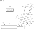
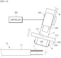
- FIGS. 8 to 10 are schematic diagrams illustrating an operation of the identification mark recognition device 1000 of the current embodiment.
- FIG. 11 is a flowchart of operations of the identification mark recognition device 1000 of the current embodiment.
- the electrode assembly 10 is transferred by a conveyor or the like and placed below the identification mark reader 100 (S10).
- a unit cell may also be disposed below the identification mark reader 100.
- an outermost electrode tab T' among the electrode tabs T of the electrode assembly 10 may be pushed out or lean to one side and thus be bent during the manufacture of the electrode assembly 10.
- the controller 300 controls the linear movement mechanism 400 to move the electrode tab pressing unit 200 toward the electrode tab T, as shown in FIG. 8 .
- the electrode tab pressing unit 200 presses the outermost electrode tab T' or a plurality of electrode tabs T until the outermost electrode tab T' is aligned to be perpendicular to the identification mark reader 100 (S20). In this case, as shown in FIG. 9 , the deformation of the outermost electrode tab T' is canceled and thus the identification mark reader 100 may easily identify the identification mark I on the outermost electrode tab T'.
- a linear movement stroke of the linear movement mechanism 400 for the electrode tab pressing unit 200 to press the electrode tab T may be set and stored in advance by the controller 300.
- the controller 300 may control the linear movement mechanism 400 by the stored stroke to allow the electrode tab pressing unit 200 to press the electrode tab T regularly.
- the linear movement stroke of the linear movement mechanism 400 may be appropriately selected in consideration of a thickness of all the electrode tabs T of the electrode assembly 10 below the identification mark reader 100, the distance between the identification mark reader 100 and the electrode tabs T, and whether the electrode tab pressing unit 200 is in contact with the transfer equipment of the electrode assembly 10. For example, when the stroke is excessively increased, the string bracket 220 of the electrode tab pressing unit 200 may apply impact the transfer equipment, thus causing damage to the transfer equipment.
- the controller 300 controls the identification mark reader 100 to identify the identification mark on the outermost electrode tab T' as shown in FIG. 9 (S30).
- the through-hole 211 and the identification mark reader 100 are arranged on the same axis. Therefore, the identification mark reader 100 may easily identify the identification mark I through the through-hole 211.
- the electrode assembly 10 may be transferred by a conveyor or the like to perform a next process (S50).
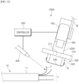
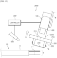
- FIGS. 12 to 15 are schematic diagrams illustrating an operation of the identification mark recognition device 2000 of a second embodiment.
- FIG. 16 is a flowchart of operations of the identification mark recognition device 2000 of the current embodiment.
- an outermost electrode tab T" of an electrode assembly 10 may be excessively bent.
- the electrode tab T" when the electrode tab T" is directly pressed, the electrode tab T" is additionally deformed in a direction in which the electrode tab T" has been deformed, thus causing damage to the electrode tab T". Therefore, before pressing the electrode tab T", it is necessary to reduce a degree of curvature of the electrode tab T" to some extent.
- the identification mark recognition device 2000 is different from the identification mark recognition device 1000 of the first embodiment in that the identification mark recognition device 2000 further includes an air injector 600 that injects air to the electrode tab T" before the electrode tab T" is pressed.
- the identification mark recognition device 2000 may also apply to the present embodiment and thus a detailed description thereof is omitted here.
- the air injector 600 may be an air nozzle for injecting compressed air.
- an electrode tab pressing unit 200 may press electrode tabs T more stably.
- foreign substances such as dust that may be attached to an identification mark I or a lighting glass 520 of a lighting member 500 may be removed by injected air. In this case, an identification mark recognition rate of an identification mark reader 100 may greatly improve.
- Control performed by the controller 300' may be similar to control performed by the controller 300 according to the first embodiment.
- operation S11 of pre-aligning electrode tabs may be added between operations S10 and S20, and the other operations S30 to S50 may be controlled in the same manner as in the first embodiment.
- controller 300' may control a linear movement mechanism 400 to allow the electrode tab pressing unit 200 to press the electrode tab to be aligned.
- the identification mark reader 100 identifies an identification mark I on the electrode tab T" (S30).
- the air injector 600 may continuously inject air.
- the injection of air may be ended at a point in time when the pressing by the electrode tab pressing unit 200 is completed.
- a point in time when the injection of air is ended is not particularly limited, as long as the air injector 600 pre-aligns the electrode tabs T and the pressing of the electrode tabs T by the electrode tab pressing unit 200 is completed.
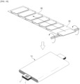
- the unit cells stacked by rolling them up with the separator sheet SS also include electrode tabs T on which the identification mark I is marked.
- the identification mark I is also provided on an electrode tab T' of a unit cell (e.g., a bi-cell BC) stacked on the top of the stack of folded cells.
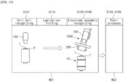
- the electrode tab pressing unit 200 of the identification mark recognition device 1000 may be used to align upper surfaces of the electrode tabs to be perpendicular to the identification mark reader.
- the identification mark reader 100 may identify the identification mark on the electrode tabs in a state in which the electrode tabs are perpendicular to the identification mark reader 100 (S140).
- the identification mark I on the electrode tab T' of the uppermost unit cell of the electrode assembly may be a representative identification (ID) of the electrode assembly.
- the electrode assembly whose representative ID has been identified may be moved to perform a subsequent process (S150).
- a subsequent process S150
- such electrode assemblies are moved to a work stage WS2 of the subsequent process by an unloader or a conveyor (not shown).
- various processes are performed on the electrode assembly. For example, a process of cutting the electrode tabs of the electrode assembly 10 and welding electrode leads, a process of putting the electrode assembly with the welded electrode leads into a case and injecting an electrolyte to manufacture a so-called packaging cell, an activation process for giving electrical characteristics to the packaging cell, a process of assembling activated secondary battery cells to manufacture a module and a pack, etc. are performed.
Landscapes
- Engineering & Computer Science (AREA)
- Physics & Mathematics (AREA)
- Chemical & Material Sciences (AREA)
- Chemical Kinetics & Catalysis (AREA)
- Electrochemistry (AREA)
- General Chemical & Material Sciences (AREA)
- Electromagnetism (AREA)
- General Physics & Mathematics (AREA)
- Theoretical Computer Science (AREA)
- Health & Medical Sciences (AREA)
- Toxicology (AREA)
- Artificial Intelligence (AREA)
- Computer Vision & Pattern Recognition (AREA)
- General Health & Medical Sciences (AREA)
- Manufacturing & Machinery (AREA)
- Secondary Cells (AREA)
Abstract
Description
- The present invention relates to an identification mark recognition device and method for identifying an identification mark on an electrode tab. The present invention also relates to a secondary battery manufacturing method using the identification mark recognition device and method.
- More specifically, the present invention relates to an identification mark recognition device for aligning an electrode tab with respect to an identification mark reader to improve a recognition rate of the identification mark reader, an identification mark recognition method, and a secondary battery manufacturing method.
- The present application claims the benefit of priority based on
Korean Patent Application No. 10-2023-0014401, filed on February 2, 2023 - Recently, chargeable and dischargeable secondary batteries have been widely used as energy sources for wireless mobile devices. In addition, secondary batteries have attracted attention as energy sources of electric vehicles, hybrid electric vehicles, etc., and are suggested as a solution to air pollution due to existing gasoline vehicles and diesel vehicles using fossil fuels.
- A secondary battery is manufactured by a number of sub-processes such as a process involving coating a current collector with an active material and rolling the current collector to manufacture positive electrodes and negative electrodes, a notching process involving forming electrode tabs, an electrode assembly manufacturing process for manufacturing an electrode assembly using the manufactured electrodes and separators, a packaging process for accommodating the electrode assembly in a case, and a charging/discharging process for providing characteristics before shipment.
- An identification mark may be marked on electrode tabs of the electrodes (the positive and negative electrodes) to check and track an intermediate product during a manufacturing process. When an electrode is put into a predetermined sub-process, the identification mark on the electrode tab may be identified to specify the electrode. In addition, information about the identification mark may be connected with information about the sub-processes to track the sub-process into which the electrode is currently put.
- However, the electrode tabs are very thin and thus are likely to be bent or crumpled during the transfer of the electrodes. In particular, when electrodes and a separator are stacked to form an electrode assembly, the lifting or crumpling of electrode tabs may become severe due to various factors, such as when the electrode tabs lean to one side or are pushed out.
- As described above, when the electrode tabs on which an identification mark is marked are bent or crumpled, irregular light reflection may occur, thus causing the identification mark to be out of focus on an identification mark reader when the identification mark is identified. In addition, the identification mark may not be located in the field of view of the identification mark reader. In this case, a recognition error of the identification mark may occur, thus making it difficult to track an intermediate product during the manufacturing process.
- Therefore, there is a need to develop a technique for aligning electrode tabs to be in the field of view of the dentification mark reader even when the electrode tabs are bent.
- (Patent Document 1)
Chinese Patent Laid-Open Publication No. 113156528 - To address the above-described problem, the present invention is directed to providing an identification mark recognition device for increasing a recognition rate of an identification mark reader by pressing electrode tabs to be aligned with respect to the identification mark reader, an identification mark recognition method, and a secondary battery manufacturing method.
- According to one aspect of the present invention, an identification mark recognition device includes: an identification mark reader configured to identify an identification mark on an electrode tab of a unit cell or an electrode assembly; an electrode tab pressing unit configured to press the electrode tab to cause a surface of the electrode tab on which the identification mark is marked to be aligned with respect to the identification mark reader; and a controller configured to control the electrode tab pressing unit and the identification mark reader to allow the identification mark reader to identify the identification mark after the pressing of the electrode tab by the electrode tab pressing unit, in which the electrode tab pressing unit is arranged to be inclined at a predetermined angle with respect to the unit cell or the electrode assembly.
- The identification mark reader may be arranged over the unit cell or the electrode assembly at the same angle as the angle at which the electrode tab pressing unit is arranged to be on the same axis as the electrode tab pressing unit, the electrode tab pressing unit may be coupled to the identification mark reader and configured to be movable from the identification mark reader, and the electrode tab pressing unit is configured to press the surface of the electrode tab on which the identification mark is marked, as the electrode tab pressing unit is moved toward the electrode tab from the identification mark reader.
- An end of the electrode tab pressing unit in a direction of pressing by the electrode tab pressing unit may be provided with a plurality of pressing strings configured to press the electrode tab.
- Outer surfaces of the plurality of pressing strings may be coated with fluorinated ethylene propylene (FEP) or poly tetrafluoro ethylene (PTFE).
- The plurality of pressing strings may be arranged to be parallel to a direction in which the electrode tab extends from a body part of the unit cell or a body part of the electrode assembly.
- The plurality of pressing strings may be arranged to press surfaces of the electrode tab that are spaced a predetermined distance from both sides of the identification mark.
- The electrode tab pressing unit may include a main body frame with a through-hole, and a plurality of string brackets installed on the main body frame that protrude from the main body frame in the direction of pressing by the electrode tab pressing unit, the plurality of string brackets may be arranged to face each other with the through-hole interposed therebetween, and both ends of the plurality of pressing strings may be fixed on the plurality of string brackets facing each other.
- The plurality of pressing strings may be coupled to the plurality of string brackets to cover ends of the plurality of string brackets facing each other, and the end of each of the plurality of string brackets facing each other may be provided with a chamfer surface inclined toward the other string bracket.
- The identification mark reader may be slantingly arranged over the unit cell or the electrode assembly to be on the same axis as the through-hole.
- The identification mark may be bar-code or quick response (QR) code.
- The identification mark recognition device may further include a lighting member between the identification mark reader and the electrode tab, and the lighting member may be on the same axis as the identification mark reader.
- The identification mark recognition device may further include an air injector configured to inject air toward the electrode tab before the electrode tab is pressed by the electrode tab pressing unit.
- According to another aspect of the present invention, an identification mark recognition method includes: placing a unit cell or an electrode assembly, which includes an electrode tab on which an identification mark is marked, below an identification mark reader; moving an electrode tab pressing unit toward the electrode tab to press the electrode tab causing the electrode tab to be perpendicular to the identification mark reader; and identifying the identification mark on the electrode tab by the identification mark reader in a state in which the electrode tab is perpendicular to the identification mark reader.
- The identification mark recognition method may further include injecting air toward the electrode tab before the pressing of the electrode tab by the electrode tab pressing unit.
- According to another aspect of the present invention, a secondary battery manufacturing method includes: preparing a plurality of unit cells including electrode tabs on which an identification mark is marked; manufacturing an electrode assembly by stacking the plurality of unit cells with a separator interposed therebetween or rolling up the plurality of unit cells placed on a separator sheet with the separator sheet; placing the electrode assembly below an identification mark reader; pressing the electrode tab of an uppermost unit cell of the electrode assembly to be perpendicular to the identification mark reader; and identifying the identification mark on the electrode tab with the identification mark reader in a state in which the electrode tab is perpendicular to the identification mark reader.
- The plurality of unit cells may be a half-cell, a mono-cell or a bi-cell.
- The electrode assembly may include unit cells of the same type or unit cells of different types.
- The secondary battery manufacturing method may further include identifying the electrode tabs of the unit cells with a separate identification mark reader before the manufacturing of the electrode assembly.
- According to the present invention, an identification mark on an electrode tab can be identified more effectively by eliminating the electrode tab from being bent or crumpled.
-
-
FIG. 1 is a schematic view of an electrode assembly. -
FIG. 2 is a perspective view of an identification mark recognition device according to a first embodiment. -
FIG. 3 is an exploded perspective view of an identification mark recognition device of the first embodiment. -
FIG. 4 is a perspective view of an electrode tab pressing unit. -
FIG. 5 is a bottom view of the electrode tab pressing unit. -
FIG. 6 is a front view of the electrode tab pressing unit. -
FIG. 7 is a schematic diagram illustrating an example in which a pressing string is coupled to a string bracket. -
FIGS. 8 to 10 are schematic diagrams illustrating an operation of the identification mark recognition device of the first embodiment. -
FIG. 11 is a flowchart of operations of the identification mark recognition device according to the first embodiment. -
FIGS. 12 to 15 are schematic diagrams illustrating an operation of the identification mark recognition device according to a second embodiment. -
FIG. 16 is a flowchart of operations of the identification mark recognition device according to the second embodiment. -
FIG. 17 is a schematic diagram illustrating a process of manufacturing a stack of cells. -
FIG. 18 is a schematic diagram illustrating a process of manufacturing folded cells or a stack of folded cells. -
FIG. 19 is a schematic diagram illustrating part of a secondary battery manufacturing process using an identification mark recognition device. -
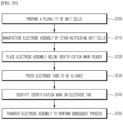
FIG. 20 is a flowchart of a secondary battery manufacturing method according to a third embodiment. - Hereinafter, the present invention will be described in detail. Before describing the present invention, the terms or expressions used in the present specification and claims should not be construed as being limited to as generally understood or as defined in commonly used dictionaries, and should be understood according to meanings and concepts matching corresponding to the present invention on the basis of the principle that the inventor(s) of the application can appropriately define the terms or expressions to optimally explain the present invention.
- It should be understood that the terms "comprise" and/or "comprising", when used herein, specify the presence of stated features, integers, steps, operations, elements, components, or a combination thereof, but do not preclude the presence or addition of one or more features, integers, steps, operations, elements, components, or a combination thereof. It should be understood that when a component such as a layer, a film, a region, a plate or the like is referred to as being "on" another component, the component is "right on" the other component or another component is interposed between these components. It should be understood that when a component such as a layer, a film, a region, a plate or the like is referred to as being "below" another component, the component is "right below" the other component or another component is interposed between these components. In addition, it should be understood that when a component is "on" another component, the component is on or below the other component.
- An identification mark recognition device of the present invention may be placed in a transfer path of a unit cell or an electrode assembly. When the unit cell or the electrode assembly is input into or output from a predetermined sub-process, the traceability of an intermediate product of a battery cell can be more easily secured in an entire manufacturing process of the battery cell by effectively identifying an identification mark on electrode tabs.
- The identification mark may be marked on the electrode tabs in the form of bar-code, quick response (QR) code, or numbers. The identification mark may be printed on the electrode tabs using ink or the like or be engraved in or embossed on the electrode tabs. A form of the identification mark or a method of marking the identification mark on the electrode tabs is not particularly limited, as long as the identification mark can be marked on one surface of each of the electrode tabs and identified by an identification mark reader.
- In the present invention, a "unit cell" should be understood as one electrode (a positive electrode or a negative electrode), a half-cell, a mono-cell, or a bi-cell. The electrode may be manufactured by coating one surface or both surfaces of an electrode plate (electrode current collector) with an electrode slurry and forming electrode tabs by a notching process. The half-cell may be manufactured by stacking one electrode and a separator together. The mono-cell may be manufactured by sequentially stacking a positive electrode, a separator, and a negative electrode. The bi-cell may be manufactured by sequentially stacking two first electrodes and a second electrode with polarity different from that of the first electrodes with a separator interposed therebetween. For example, the bi-cell may be manufactured by sequentially stacking a positive electrode, a separator, a negative electrode, a separator, and a positive electrode. Alternatively, the bi-cell may be manufactured by sequentially stacking a negative electrode, a separator, a positive electrode, a separator, and a negative electrode.
- In the present invention, an "electrode assembly" may be manufactured by stacking a plurality of unit cells with separators interposed therebetween. For example, the electrode assembly may be manufactured by stacking a plurality of bi-cells on a separator and winding the separator.
- Hereinafter, for convenience of description and illustration, embodiments of the present invention will be described with respect to an "electrode assembly." That is, the following description may apply to a "unit cell".
-
FIG. 1 is a schematic view of anelectrode assembly 10. - (a) of
FIG. 1 is a perspective view of theelectrode assembly 10, and (b) ofFIG. 1 is a side view of theelectrode assembly 10. - As shown in
FIG. 1 , theelectrode assembly 10 includes a plurality of electrode tabs T. An identification mark may be marked on each of the electrode tabs T. An identification mark reader may identify a identification mark I on an outermost electrode tab T' among the plurality of electrode tabs T. In this case, the identification mark I is exposed to the outside, making it easy for the identification mark reader to identify the identification mark I. - As illustrated in
FIG. 1 , the electrode tabs T may extend from abody part 11 of theelectrode assembly 10 to both ends of theelectrode assembly 10. However, the electrode tabs T may extend to one end of thebody part 11 according to the design of theelectrode assembly 10. - Hereinafter, an identification mark recognition device of the present invention will be described in detail with reference to the drawings.
-
FIG. 2 is a perspective view of an identificationmark recognition device 1000 according to the present invention, andFIG. 3 is an exploded perspective view of the identificationmark recognition device 1000. - As shown in
FIGS. 2 and3 , the identificationmark recognition device 1000 includes anidentification mark reader 100 that identifies an identification mark I on an electrode tab T of anelectrode assembly 10, an electrodetab pressing unit 200 that presses the electrode tab T to be aligned, and acontroller 300 that controls theidentification mark reader 100 and the electrodetab pressing unit 200. - The
identification mark reader 100 may identify the identification mark I on the electrode tab T by photographing or scanning the electrode tab T. Theidentification mark reader 100 may be, for example, a barcode reader. However, the present invention is not limited thereto and is not particularly limited as long as the identification mark I can be identified or photographed. - As shown in
FIGS. 2 and3 , theidentification mark reader 100 may be provided over theelectrode assembly 10. To this end, a mounting bracket M may be installed on the identificationmark recognition device 1000 over the electrode assembly to be transferred, and theidentification mark reader 100 may be coupled to the mounting bracket M. In this case, theidentification mark reader 100 may be provided on an outermost electrode tab T among the electrode tabs T of theelectrode assembly 10 to identify an identification mark I on an electrode tab T facing theidentification mark reader 100 as a representative identification mark I of theelectrode assembly 10. - Alternatively, although not shown, the
identification mark reader 100 may be provided below theelectrode assembly 10. In this case, theidentification mark reader 100 may identify an identification mark I on an electrode tab T located on a lower portion of an outermost part of theelectrode assembly 10 as a representative identification mark I of theelectrode assembly 10. - The mounting bracket M may be a general metal bracket with a predetermined thickness. A shape, material, etc. of the mounting bracket M are not particularly limited as long as the
identification mark reader 100 can be fixed to an upper or lower part of a transfer path of theelectrode assembly 10. - The
identification mark reader 100 may be connected to thecontroller 300 via wire or wirelessly. Theidentification mark reader 100 may identify the identification mark I by photographing the electrode tab T according to an operation signal from thecontroller 300. In addition, theidentification mark reader 100 may transmit obtained information about the identified identification mark I to thecontroller 300. - The electrode
tab pressing unit 200 presses the electrode tab such that a surface of the electrode tab on which the identification mark I is marked and theidentification mark reader 100 are aligned perpendicular to each other. - The electrode
tab pressing unit 200 is arranged slantly at a predetermined angle with respect to a unit cell or theelectrode assembly 10. As shown inFIG. 1 , thebody part 11 of theelectrode assembly 10 is thicker than a portion of theelectrode assembly 10 from which the electrode tab T protrudes. This also applies to the unit cell. Accordingly, when the electrodetab pressing unit 200 presses the electrode tab T perpendicular to theelectrode assembly 10, the electrode tab T is continuously pressed in contact with thebody part 11, thus causing damage to the body part 11 (e.g., tearing of the separator, damage to an electrode active material, etc.). However, when the electrodetab pressing unit 200 is arranged slantly, a pressing surface of the electrodetab pressing unit 200 may be first brought into contact with the electrode tab T to minimize damage of thebody part 11. - In addition, when the electrode
tab pressing unit 200 is excessively inclined, the electrode tab T may be severely deformed (warped or bent) when pressed by the electrodetab pressing unit 200. Accordingly, the above-described angle may be appropriately selected within a range that prevents the electrode tab T from being deformed (warped or bent) when pressed by the electrodetab pressing unit 200. - As shown in
FIGS. 2 and3 , an end of the electrodetab pressing unit 200 in a direction of pressing by the electrodetab pressing unit 200 may be provided with a plurality ofpressing strings 230 for pressing the electrode tab T. - By providing the
pressing strings 230, the electrodetab pressing unit 200 may come into line contact with the electrode tab T by thepressing strings 230 when the electrodetab pressing unit 200 applies pressure. Therefore, a sufficient pressing force may be applied to the electrode tab T by employing thepressing strings 230 instead of other pressing members or alignment members configured to be in point contact with the electrode tab T. In addition, damage to the electrode tab T may be minimized by employing thepressing strings 230 instead of other pressing members or alignment members configured to be in surface contact with the electrode tab T. - The
pressing strings 230 may be disposed parallel with a direction in which the electrode tab T extends from a body part of a unit cell or thebody part 11 of theelectrode assembly 10. An end portion of the electrode tab T may be displaced due to the deformation, such as bending or crumpling, of the electrode tab T. When thepressing strings 230 are disposed perpendicular to the direction in which the electrode tab T extends, the end portion of the electrode tab T may not be capable of being pressed according to a degree of displacement of the end portion of the electrode tab T. However, when thepressing strings 230 are disposed parallel with the direction in which the electrode tab T extends, thepressing strings 230 may come into line contact with the end portion of the electrode tab T to be perpendicular to the end portion. Therefore, the electrode tab T may be effectively aligned by pressing the end portions thereof in a direction opposite to a direction in which the end portions are displaced. - The pressing strings 330 should be appropriately disposed such that the identification mark I is not hidden in a field of view of the
identification mark reader 100 when the electrode tab T is pressed by the electrodetab pressing unit 200. To this end, the pressing strings 330 are preferably disposed to press surfaces of the electrode tab T that are spaced a predetermined distance from both ends of the identification mark I. - The number and arrangement of the pressing strings 330 may be appropriately selected such that the identification mark I is not hidden in the field of view of the
identification mark reader 100. - An outer surface of the pressing string 330 may be coated with fluorinated ethylene propylene (FEP) or poly tetrafluoro ethylene (PTFE). The FEP and the PTFE are materials with a significantly low coefficient of friction. Therefore, when the outer surface of the pressing string 330 is coated with the FEP or PTFE, damage to the electrode tab T due to friction between the pressing string 330 and the electrode tab T may be minimized when the electrode tab T is pressed.
- As shown in
FIG. 3 , the electrodetab pressing unit 200 may include amain body frame 210 with a through-hole 211 and astring bracket 220 in which thepressing string 230 is installed. -
FIG. 4 is a perspective view of the electrodetab pressing unit 200.FIG. 5 is a bottom view of the electrodetab pressing unit 200.FIG. 6 is a front view of the electrodetab pressing unit 200.FIG. 7 is a schematic diagram illustrating an example in which thepressing string 230 is coupled to thestring bracket 220. - As shown in
FIGS. 4 to 6 , themain body frame 210 may have a rectangular frame shape. However, the present invention is not limited thereto, and a shape of themain body frame 210 may be appropriately selected as long as thestring bracket 220 can be installed. - The through-
hole 211 may be provided in a central area of themain body frame 210 as shown inFIGS. 4 and 5 . Total weight of themain body frame 210 may be reduced by providing the through-hole 211 in themain body frame 210. - The through-
hole 211 extends in a height direction of themain body frame 210. That is, themain body frame 210 includes the through-hole 211 and thus may have a rectangular frame shape, the central part of which is empty. Therefore, even when the electrode tab T is pressed by the electrodetab pressing unit 200, theidentification mark reader 100 may easily identify the identification mark I through the through-hole 211. - The
pressing string 230 may be installed on an inner wall of the through-hole 211. However, in this case, when the electrode tab T is pressed, a conveyor that transfers theelectrode assembly 10 may come into contact with an outer circumferential surface of thepressing string 230 and thus be damaged. Therefore, as shown inFIGS. 4 to 6 , a plurality ofstring brackets 220 are preferably installed on themain body frame 210 to protrude from themain body frame 210 in a direction in which the electrode tab T is pressed by the electrodetab pressing unit 200. - The
string brackets 220 may be disposed to face each other with the through-hole 211 interposed therebetween. In this case, both ends of thepressing string 230 are fixed to thestring brackets 220 facing each other and thus thepressing string 230 may be located on an end of the electrodetab pressing unit 200 in the direction of pressing. - An even number of
string brackets 220 are preferably provided because the both ends of thepressing string 230 are fixed to thestring brackets 220. For example, as shown inFIGS. 4 to 6 , a pair ofstring brackets 220 that are symmetrical to each other may be provided. However, the providing of the pair ofstring brackets 220 is only an example, and the number ofstring brackets 220 to be installed is not particularly limited as long as both ends of thepressing string 230 can be easily fixed. - The
string brackets 220 are disposed to be spaced a predetermined distance from each other with the through-hole 211 interposed therebetween. In addition, because the electrodetab pressing unit 200 is disposed slantly, thestring brackets 220 are also disposed slantly. Therefore, when thestring brackets 220 are installed on themain body frame 210 to be excessively spaced apart from each other, thestring brackets 220 may apply impact to transfer equipment (e.g., a conveyor) of theelectrode assembly 10 when the electrode tab T is pressed. In this case, the transfer equipment may be damaged by thestring brackets 220. Therefore, a distance between thestring brackets 220 may be appropriately set to prevent thestring brackets 220 from being in contact with the transfer equipment of theelectrode assembly 10 when the electrodetab pressing unit 200 presses the electrode tab T. In addition, a length of thepressing strings 230 may be determined according to the distance between thestring brackets 220. - The
string brackets 220 may be plates having a square shape with a predetermined thickness. A shape and thickness of thestring brackets 220 may be appropriately changed according to the design of thestring brackets 220 or the electrodetab pressing unit 200. - As shown in
FIG. 7 , thestring bracket 220 may be provided with a screwinghole 221 to install thepressing string 230. - As shown in
FIG. 7 , thepressing string 230 may be coupled to thestring bracket 220 by winding both ends of thepressing string 230 around bolts B and screwing the bolts B into screwingholes 221. However, the above coupling method is only one example, and other coupling methods may also be appropriately selected as long as thepressing string 230 can be fixed to thestring bracket 220. - As shown in
FIG. 7 , thepressing strings 230 may be coupled to cover ends of thestring brackets 220 facing each other. That is, one end of each of thepressing strings 230 may be fixed to the screwinghole 221, and main bodies thereof extending from both ends of thepressing strings 230 may be bent towardother string brackets 220 facing each other. - In this case, the
pressing strings 230 may be excessively bent due to edges of ends of thestring brackets 220, thus causing stress to be applied to thepressing strings 230. To minimize stress to be applied, achamfer surface 222 inclined toward theother string brackets 220 facing each other may be provided as shown inFIG. 7 . - The
chamfer surface 222 may be formed by chamfering an end surface of thestring bracket 220. - In
FIG. 7 , thechamfer surface 222 is shown as a flat surface. However, thechamfer surface 222 may be manufactured to be a curved surface bulging toward the direction of pressing. - The electrode
tab pressing unit 200 may be coupled to theidentification mark reader 100 to be movable from theidentification mark reader 100. As the electrodetab pressing unit 200 is moved toward the electrode tab T from theidentification mark reader 100, the identification mark on the electrode tab T may be pressed by the electrodetab pressing unit 200. - As shown in
FIG. 2 , theidentification mark reader 100 may be positioned on the same axis as the electrodetab pressing unit 200. To this end, theidentification mark reader 100 may be placed over theelectrode assembly 10 at the same angle as the angle at which the electrodetab pressing unit 200 is placed. - In this case, as shown in
FIG. 3 , the through-hole 211 and theidentification mark reader 100 are arranged on the same axis. In this case, theidentification mark reader 100 may be placed on a unit cell. - By arranging the
identification mark reader 100 and the electrodetab pressing unit 200 on the same axis, interference caused by the structure of the electrodetab pressing unit 200 may be minimized when the identification mark I is identified by theidentification mark reader 100. Therefore, even when the electrodetab pressing unit 200 presses the electrode tab T, the identification mark I may be positioned in the field of view of theidentification mark reader 100 through the through-hole 211. In addition, the layout design of theidentification mark reader 100 and the electrodetab pressing unit 200 may be simplified by arranging theidentification mark reader 100 and the electrodetab pressing unit 200 at the same angle. - In the present embodiment, the electrode
tab pressing unit 200 moves linearly back and forth. The identificationmark recognition device 1000 of the present embodiment may include alinear movement mechanism 400 for linear movement of the electrodetab pressing unit 200. - The
linear movement mechanism 400 may be a pneumatic or hydraulic cylinder, a direction of linear movement of which changes according to a direction in which a fluid is supplied. However, thelinear movement mechanism 400 is not limited thereto, and is not particularly limited as long as thelinear movement mechanism 400 is capable of moving linearly back and forth according to an operating signal from thecontroller 300. - As shown in
FIGS. 2 and3 , one end of thelinear movement mechanism 400 may be coupled to the mounting bracket M, and another end thereof may be connected to the electrodetab pressing unit 200 through a connection bracket C. In this case, a linear movement part (e.g., a cylinder rod) of thelinear movement mechanism 400 moves linearly, thus causing the connection bracket C to be moved linearly. In this case, because the electrodetab pressing unit 200 is coupled to the connecting bracket C, the electrodetab pressing unit 200 is also moved linearly together with the connection bracket C. As described above, the electrodetab pressing unit 200 is coupled to theidentification mark reader 100 to be movable from theidentification mark reader 100 by thelinear movement mechanism 400. - A shape of the connection bracket C is not particularly limited as long as an appropriate mounting surface can be provided to connect the electrode
tab pressing unit 200 to thelinear movement mechanism 400. - As shown in
FIGS. 2 and3 , the identificationmark recognition device 1000 of the present embodiment may further include alighting member 500 between theidentification mark reader 100 and the electrode tab T. - The
lighting member 500 may emit light onto a surface of the electrode tab T on which the identification mark I is marked to assist theidentification mark reader 100 to identify the identification mark I. - The
lighting member 500 may include alighting frame 510 in which a light source is installed andlighting glass 520 installed in a central area of thelighting member 500. - The
lighting frame 510 may be manufactured in a square frame shape whose central part is empty. A light source that generates light may be installed inside thelighting frame 510. In this case, the empty central part of thelighting frame 510 may be covered with thelighting glass 520 to protect the light source from external contaminants (dust, etc.). - The
lighting member 500 may be arranged on the same axis as theidentification mark reader 100. As described above, because thelighting member 500 and theidentification mark reader 100 are arranged in a straight line, an amount of light that is emitted to the electrode tab T, reflected and collected on theidentification mark reader 100 may be maximized. Therefore, theidentification mark reader 100 may identify the identification mark I more clearly. - The
lighting member 500 may also be arranged on the same axis as the electrodetab pressing unit 200 as shown inFIGS. 2 and3 . In this case, as shown inFIG. 3 , thelighting frame 510 may be connected to the connection bracket C, and the electrodetab pressing unit 200 may be coupled to thelighting frame 510. To this end, themain body frame 210 of the electrodetab pressing unit 200 may include aconnection block 212 to be coupled to thelighting frame 510. - The
connection block 212 may be provided with acoupling hole 212a. The electrodetab pressing unit 200 and thelighting member 500 may be coupled to each other by fixing a separate fastening member, such as a bolt, in thelighting frame 510 while passing through thecoupling hole 212a. - The electrode
tab pressing unit 200 aligns the electrode tab T such that the surface of the electrode tab T on which the identification mark I is marked is perpendicular to theidentification mark reader 100, before the identification mark I is identified by theidentification mark reader 100. As described above, an identification mark recognition rate of theidentification mark reader 100 may be improved by aligning the electrode tab T at a predetermined position. - The identification
mark recognition device 1000 includes thecontroller 300 that controls theidentification mark reader 100 and thelinear movement mechanism 400. - The
controller 300 may be an equipment control program that controls equipment in each sub-process. Alternatively, thecontroller 300 may be separate software installed in an entire process control system. -
FIGS. 8 to 10 are schematic diagrams illustrating an operation of the identificationmark recognition device 1000 of the current embodiment.FIG. 11 is a flowchart of operations of the identificationmark recognition device 1000 of the current embodiment. - First, the
electrode assembly 10 is transferred by a conveyor or the like and placed below the identification mark reader 100 (S10). In this case, a unit cell may also be disposed below theidentification mark reader 100. - As shown in
FIG. 8 , an outermost electrode tab T' among the electrode tabs T of theelectrode assembly 10 may be pushed out or lean to one side and thus be bent during the manufacture of theelectrode assembly 10. - When the
electrode assembly 10 is disposed below theidentification mark reader 100, thecontroller 300 controls thelinear movement mechanism 400 to move the electrodetab pressing unit 200 toward the electrode tab T, as shown inFIG. 8 . - The electrode
tab pressing unit 200 presses the outermost electrode tab T' or a plurality of electrode tabs T until the outermost electrode tab T' is aligned to be perpendicular to the identification mark reader 100 (S20). In this case, as shown inFIG. 9 , the deformation of the outermost electrode tab T' is canceled and thus theidentification mark reader 100 may easily identify the identification mark I on the outermost electrode tab T'. - A linear movement stroke of the
linear movement mechanism 400 for the electrodetab pressing unit 200 to press the electrode tab T may be set and stored in advance by thecontroller 300. Thecontroller 300 may control thelinear movement mechanism 400 by the stored stroke to allow the electrodetab pressing unit 200 to press the electrode tab T regularly. - In this case, the linear movement stroke of the
linear movement mechanism 400 may be appropriately selected in consideration of a thickness of all the electrode tabs T of theelectrode assembly 10 below theidentification mark reader 100, the distance between theidentification mark reader 100 and the electrode tabs T, and whether the electrodetab pressing unit 200 is in contact with the transfer equipment of theelectrode assembly 10. For example, when the stroke is excessively increased, thestring bracket 220 of the electrodetab pressing unit 200 may apply impact the transfer equipment, thus causing damage to the transfer equipment. - When the outermost electrode tab T' is aligned, the
controller 300 controls theidentification mark reader 100 to identify the identification mark on the outermost electrode tab T' as shown inFIG. 9 (S30). In this case, as shown inFIG. 9 , the through-hole 211 and theidentification mark reader 100 are arranged on the same axis. Therefore, theidentification mark reader 100 may easily identify the identification mark I through the through-hole 211. - Thereafter, as shown in
FIG. 10 , thecontroller 300 controls thelinear movement mechanism 400 to cause the electrodetab pressing unit 200 to return to an original position (S40). - As the electrode
tab pressing unit 200 returns to the original positions and the pressing of the electrode tabs T and T' is canceled, theelectrode assembly 10 may be transferred by a conveyor or the like to perform a next process (S50). -
FIGS. 12 to 15 are schematic diagrams illustrating an operation of the identificationmark recognition device 2000 of a second embodiment.FIG. 16 is a flowchart of operations of the identificationmark recognition device 2000 of the current embodiment. - As shown in
FIG. 12 , an outermost electrode tab T" of anelectrode assembly 10 may be excessively bent. In this case, when the electrode tab T" is directly pressed, the electrode tab T" is additionally deformed in a direction in which the electrode tab T" has been deformed, thus causing damage to the electrode tab T". Therefore, before pressing the electrode tab T", it is necessary to reduce a degree of curvature of the electrode tab T" to some extent. - In the present embodiment, the identification
mark recognition device 2000 is different from the identificationmark recognition device 1000 of the first embodiment in that the identificationmark recognition device 2000 further includes anair injector 600 that injects air to the electrode tab T" before the electrode tab T" is pressed. In addition, components of the identificationmark recognition device 2000 that are the same as those of the identificationmark recognition device 1000 of the first embodiment may also apply to the present embodiment and thus a detailed description thereof is omitted here. - The
air injector 600 may be an air nozzle for injecting compressed air. - A position at which the
air injector 600 is installed is not particularly limited as long theair injector 600 is capable of injecting compressed air in a direction toward which the outermost electrode tab T" extends. - In the present embodiment, excessive deformation of the electrode tab T" may be eliminated to some extent by displacing the excessively deformed (bent) electrode tab T" in a direction opposite to the direction in which the electrode tab T" has been deformed by the
air injector 600. Accordingly, damage to the electrode tab T" when pressed may be minimized. Therefore, an electrodetab pressing unit 200 may press electrode tabs T more stably. In addition, foreign substances such as dust that may be attached to an identification mark I or alighting glass 520 of alighting member 500 may be removed by injected air. In this case, an identification mark recognition rate of anidentification mark reader 100 may greatly improve. - Air injection by the
air injector 600 may be controlled by a controller 300'. - Control performed by the controller 300' may be similar to control performed by the
controller 300 according to the first embodiment. For example, operation S11 of pre-aligning electrode tabs may be added between operations S10 and S20, and the other operations S30 to S50 may be controlled in the same manner as in the first embodiment. - Specifically, when the
electrode assembly 10 is located below the identification mark reader 100 (S10), the controller 300' may control theair injector 600 to pre-align the outermost electrode tab T", as shown inFIG. 12 (S11). - Thereafter, the controller 300' may control a
linear movement mechanism 400 to allow the electrodetab pressing unit 200 to press the electrode tab to be aligned. - In this case, as illustrated in
FIG. 13 , air injection by theair injector 600 may be maintained until the electrodetab pressing unit 200 presses the electrode tabs T. - Next, as illustrated in
FIG. 14 , theidentification mark reader 100 identifies an identification mark I on the electrode tab T" (S30). In this case, theair injector 600 may continuously inject air. Alternatively, the injection of air may be ended at a point in time when the pressing by the electrodetab pressing unit 200 is completed. A point in time when the injection of air is ended is not particularly limited, as long as theair injector 600 pre-aligns the electrode tabs T and the pressing of the electrode tabs T by the electrodetab pressing unit 200 is completed. - Thereafter, when the identification of the identification mark I is completed, the controller 300' causes the electrode
tab pressing unit 200 to return to an original position as shown inFIG. 15 (S40). - Finally, the
electrode assembly 10 may be transferred by a conveyor or the like to perform the next process. - As described above, the recognition rate of an identification mark I on the electrode tabs T can be improved by aligning the electrode tabs T to be perpendicular to the
identification mark reader 100. In addition, as in the present embodiment, theair injector 600 may be further provided to pre-align the electrode tabs T. In this case, the electrode tabs T may be pressed more stably. -
FIG. 17 is a schematic diagram illustrating a process of manufacturing a stack of cells.FIG. 18 is a schematic diagram illustrating a process of manufacturing folded cells or a stack of folded cells. -
FIG. 19 is a schematic diagram illustrating part of a secondary battery manufacturing process using an identification mark recognition device.FIG. 20 is a flowchart of a secondary battery manufacturing method according to a third embodiment. -
FIG. 17 illustrates a process of manufacturing a stacked celltype electrode assembly 10 by stacking unit cells. The unit cells to be stacked may be of the same type (e.g., mono-cells (MC)). Alternatively, a stack of the same type of unit cells may include different types of unit cells (e.g., half-cells). For example, half-cells may be placed at the top and/or the bottom of a stack of mono-cells. The stacked celltype electrode assembly 10 may include a fixing tape X to fix the unit cells. Each of the unit cells includes an electrode tab T on which an identification mark I is marked. An identification mark I is provided on an electrode tab T' of a unit cell (e.g., a mono-cell (MC) or a half-cell) stacked on the top of the stack of cells. - Referring to
FIG. 18 , a plurality of unit cells (e.g., bi-cells BC) are placed on a long separator sheet SS. In this state, the separator sheet SS is folded sequentially. That is, theelectrode assembly 10 may be manufactured in the form of folded cells or a stack of folded cells by rolling the bi-cells BC up with the separator sheet SS. - The unit cells stacked by rolling them up with the separator sheet SS also include electrode tabs T on which the identification mark I is marked. The identification mark I is also provided on an electrode tab T' of a unit cell (e.g., a bi-cell BC) stacked on the top of the stack of folded cells.
-
FIG. 19 illustrates a part of a secondary battery manufacturing process in which anelectrode assembly 10 is manufactured using unit cells. Referring toFIGS. 19 and20 , in order to manufacture theelectrode assembly 10, first, a plurality of unit cells with electrode tabs T on which an identification mark I is marked are prepared (S100). - The unit cells may be transferred to a work stage WS1 for manufacturing an electrode assembly. For example, the plurality of unit cells may be loaded on the work stage WS1 by a conveyor or a loader (not shown). As described above, the unit cell is a half-cell, a mono-cell, or a bi-cell. Alternatively, the electrode assembly may include unit cells of the same type or different types.
- Operation S101 of identifying the electrode tabs T of the unit cells by a separate
identification mark reader 100 may be further performed before the manufacture of theelectrode assembly 10. In this case, theidentification mark reader 100 may be of the same type as or a different type from that included in the identificationmark recognition device - In this case, when the identification mark I on each of the unit cells is identified, the electrode
tab pressing unit 200 of the identificationmark recognition device tab pressing unit 200, the electrode tabs are likely to be damaged or bent in a direction opposite to a direction of pressing. Therefore, the identification mark on each of the units cells can be identified simply by a general identification mark reader. - Next, the plurality of unit cells, the identification mark of which are identified may be moved from the work stage WS1 to perform a lamination process thereon to stack the plurality of unit cells with a separator interposed therebetween, thereby completing the
electrode assembly 10 in the form of a stack of cells. Alternatively, the plurality of unit cells on a separator may be rolled up in the separator sheet to manufacture an electrode assembly in the form of folded cells or a stack of folded cells (S110). - Manufactured electrode assemblies are moved from the work stage WS1 and placed below the identification mark reader (S120).
- In the
electrode assembly 10 described above, the plurality of unit cells are laid to overlap each other and thus the electrode tabs are very likely to be deformed due to various factors, e.g., when the electrode tabs lean to one side or be pushed out, during the stacking of the unit cells or during the rolling of the unit cells with the separator sheet SS. Accordingly, operation S130 of pressing the electrode tabs such that an electrode tab of an uppermost unit cell of the electrode assembly is perpendicular to the identification mark reader should be performed. That is, as shown inFIGS. 9 and14 , electrode tabs should be pressed to be aligned such that the electrode tab T' is perpendicular to the identification mark reader. In this case, as shown inFIGS. 9 and14 , the electrodetab pressing unit 200 of the identificationmark recognition device 1000 may be used to align upper surfaces of the electrode tabs to be perpendicular to the identification mark reader. - The
identification mark reader 100 may identify the identification mark on the electrode tabs in a state in which the electrode tabs are perpendicular to the identification mark reader 100 (S140). - The identification mark I on the electrode tab T' of the uppermost unit cell of the electrode assembly may be a representative identification (ID) of the electrode assembly.
- The representative ID may be related to information of the identification mark I on the electrode tab of each of the unit cells of the electrode assembly. That is, the types, data, etc. of the unit cells included in the electrode assembly may be identified by identifying the representative ID. In addition, the representative ID may include information about manufacturing histories, e.g., lot numbers, each piece of process equipment, and production line information.
- The ID may include symbols indicating a sequence number. The symbols may include Arabic numerals but are not limited thereto. The symbols may include arbitrary characters providing information about the sequence number.
- The electrode assembly whose representative ID has been identified may be moved to perform a subsequent process (S150). In this case, such electrode assemblies are moved to a work stage WS2 of the subsequent process by an unloader or a conveyor (not shown). In the subsequent process (S160), various processes are performed on the electrode assembly. For example, a process of cutting the electrode tabs of the
electrode assembly 10 and welding electrode leads, a process of putting the electrode assembly with the welded electrode leads into a case and injecting an electrolyte to manufacture a so-called packaging cell, an activation process for giving electrical characteristics to the packaging cell, a process of assembling activated secondary battery cells to manufacture a module and a pack, etc. are performed. - In the above subsequent processes, operations of identifying the representative ID of the electrode assembly may also be needed. Accordingly, similarly, in a subsequent process, an electrode tab of an uppermost unit cell of the electrode assembly may be pressed to be perpendicular to the identification mark reader, so that the identification mark reader may identify an identification mark on the uppermost unit cell in this state.
- Accordingly, identification information of each of unit cells and an electrode assembly including the unit cells can be accurately specified throughout an entire secondary battery manufacturing process. In addition, manufacturing histories of various types of secondary batteries can be easily figured out, based on the identification information.
- The above description is only an example of the technical idea of the present invention and various modification and changes may be made by those of ordinary skill in the technical field to which the present invention pertains without departing from the essential features of the present invention.
- Therefore, the drawings of the present invention set forth herein are intended not to limit the technical idea of the present invention but to describe the technical idea, and the scope of the technical idea of the present invention is not limited by the drawings. The scope of protection for the present invention should be interpreted based on the following claims and all technical ideas within the same scope as the present invention should be interpreted as being included in the scope of the present invention.
- In the present specification, terms representing directions such as upper, lower, left, right, forward and backward are used only for convenience of description and thus it will be obvious that these terms may be changed according to a position of an object or an observer.
-
- 10: electrode assembly
- 100: identification mark reader
- 200: electrode tab pressing unit
- 210: main body frame
- 220: string bracket
- 230: pressing string
- 300, 300': controller
- 400: linear movement mechanism
- 500: lighting member
- 600: air injector
- 1000, 2000: identification mark recognition device
- I: identification mark
- T, T', T": electrode tab
Claims (18)
- An identification mark recognition device comprising:an identification mark reader configured to identify an identification mark on an electrode tab of a unit cell or an electrode assembly;an electrode tab pressing unit configured to press the electrode tab to cause a surface of the electrode tab on which the identification mark is marked to be aligned with respect to the identification mark reader; anda controller configured to control the electrode tab pressing unit and the identification mark reader to allow the identification mark reader to identify the identification mark after the pressing of the electrode tab by the electrode tab pressing unit,wherein the electrode tab pressing unit is arranged to be inclined at a predetermined angle with respect to the unit cell or the electrode assembly.
- The identification mark recognition device of claim 1, wherein the identification mark reader is arranged over the unit cell or the electrode assembly at the same angle as the angle at which the electrode tab pressing unit is arranged, so that the identification mark reader is positioned on the same axis as the electrode tab pressing unit,the electrode tab pressing unit is coupled to the identification mark reader and configured to be movable from the identification mark reader, andthe electrode tab pressing unit is configured to press the surface of the electrode tab on which the identification mark is marked, as the electrode tab pressing unit is moved toward the electrode tab from the identification mark reader.
- The identification mark recognition device of claim 1, wherein an end of the electrode tab pressing unit in a direction of pressing by the electrode tab pressing unit is provided with a plurality of pressing strings configured to press the electrode tab.
- The identification mark recognition device of claim 3, wherein outer surfaces of the plurality of pressing strings are coated with fluorinated ethylene propylene (FEP) or poly tetrafluoro ethylene (PTFE).
- The identification mark recognition device of claim 3, wherein the plurality of pressing strings are arranged to be parallel to a direction in which the electrode tab extends from a body part of the unit cell or a body part of the electrode assembly.
- The identification mark recognition device of claim 3, wherein the plurality of pressing strings are arranged to press surfaces of the electrode tab that are spaced a predetermined distance from both sides of the identification mark.
- The identification mark recognition device of claim 3, wherein the electrode tab pressing unit comprises a main body frame with a through-hole, and a plurality of string brackets installed on the main body frame that protrude from the main body frame in the direction of pressing by the electrode tab pressing unit,wherein the plurality of string brackets are arranged to face each other with the through-hole interposed therebetween, andboth ends of the plurality of pressing strings are fixed on the plurality of string brackets facing each other.
- The identification mark recognition device of claim 7, wherein the plurality of pressing strings are coupled to the plurality of string brackets to cover ends of the plurality of string brackets facing each other, and
the end of each of the plurality of string brackets facing each other are provided with a chamfer surface inclined toward the other string bracket. - The identification mark recognition device of claim 7, wherein the identification mark reader is slantingly arranged over the unit cell or the electrode assembly to be on the same axis as the through-hole.
- The identification mark recognition device of claim 1, wherein the identification mark comprises bar-code or quick response (QR) code.
- The identification mark recognition device of claim 1, further comprising a lighting member between the identification mark reader and the electrode tab,
wherein the lighting member is on the same axis as the identification mark reader. - The identification mark recognition device of claim 1, further comprising an air injector configured to inject air toward the electrode tab before the electrode tab is pressed by the electrode tab pressing unit.
- An identification mark recognition method comprising:placing a unit cell or an electrode assembly, which includes an electrode tab on which an identification mark is marked, below an identification mark reader;moving an electrode tab pressing unit toward the electrode tab to press the electrode tab causing the electrode tab to be perpendicular to the identification mark reader; andidentifying the identification mark on the electrode tab by the identification mark reader in a state in which the electrode tab is perpendicular to the identification mark reader.
- The identification mark recognition method of claim 13, wherein an end of the electrode tab pressing unit in a direction of pressing by the electrode tab pressing unit is provided with a plurality of pressing strings,
wherein the electrode tab is pressed by the plurality of pressing strings as the electrode tab pressing unit is moved toward the electrode tab. - The identification mark recognition method of claim 13, further comprising injecting air toward the electrode tab before the pressing of the electrode tab by the electrode tab pressing unit.
- A secondary battery manufacturing method comprising:preparing a plurality of unit cells including electrode tabs on which an identification mark is marked;manufacturing an electrode assembly by stacking the plurality of unit cells with a separator interposed therebetween or rolling up the plurality of unit cells placed on a separator sheet with the separator sheet;placing the electrode assembly below an identification mark reader;pressing the electrode tab of an uppermost unit cell of the electrode assembly to be perpendicular to the identification mark reader; andidentifying the identification mark on the electrode tab with the identification mark reader in a state in which the electrode tab is perpendicular to the identification mark reader.
- The secondary battery manufacturing method of claim 16, wherein the plurality of unit cells comprises a half-cell, a mono-cell or a bi-cell, and
the electrode assembly comprises unit cells of the same type or unit cells of different types. - The secondary battery manufacturing method of claim 16, further comprising identifying the electrode tabs of the unit cells with a separate identification mark reader before the manufacturing of the electrode assembly.
Applications Claiming Priority (2)
| Application Number | Priority Date | Filing Date | Title |
|---|---|---|---|
| KR20230014401 | 2023-02-02 | ||
| PCT/KR2024/001477 WO2024162766A1 (en) | 2023-02-02 | 2024-01-31 | Identification mark recognition device, identification mark recognition method, and secondary battery manufacturing method |
Publications (2)
| Publication Number | Publication Date |
|---|---|
| EP4517580A1 true EP4517580A1 (en) | 2025-03-05 |
| EP4517580A4 EP4517580A4 (en) | 2025-12-17 |
Family
ID=92147012
Family Applications (1)
| Application Number | Title | Priority Date | Filing Date |
|---|---|---|---|
| EP24750563.9A Pending EP4517580A4 (en) | 2023-02-02 | 2024-01-31 | IDENTIFICATION MARK RECOGNITION DEVICE, IDENTIFICATION MARK RECOGNITION METHOD AND SECONDARY BATTERY MANUFACTURING METHOD |
Country Status (6)
| Country | Link |
|---|---|
| US (1) | US20250329770A1 (en) |
| EP (1) | EP4517580A4 (en) |
| JP (1) | JP2025516912A (en) |
| KR (1) | KR102840397B1 (en) |
| CN (1) | CN119301601A (en) |
| WO (1) | WO2024162766A1 (en) |
Families Citing this family (1)
| Publication number | Priority date | Publication date | Assignee | Title |
|---|---|---|---|---|
| WO2026089321A1 (en) * | 2024-10-25 | 2026-04-30 | 주식회사 엘지에너지솔루션 | Apparatus for manufacturing battery cell and system for manufacturing battery cell including same |
Family Cites Families (13)
| Publication number | Priority date | Publication date | Assignee | Title |
|---|---|---|---|---|
| JPH08185465A (en) * | 1994-12-30 | 1996-07-16 | Casio Comput Co Ltd | Code reader |
| JP2013030376A (en) * | 2011-07-29 | 2013-02-07 | Hitachi Ltd | Electrode sheet lamination type lithium ion battery or method for manufacturing the same |
| US10236497B2 (en) * | 2013-08-06 | 2019-03-19 | Nec Energy Devices, Ltd. | Intermittently coated battery electrode manufacturing method |
| KR101605229B1 (en) * | 2013-09-10 | 2016-03-21 | 주식회사 엘지화학 | Vision apparatus for measuring appearance of battery cell tab |
| KR101774261B1 (en) * | 2013-11-28 | 2017-09-04 | 주식회사 엘지화학 | Inspection Device for Secondary Battery Unit Cell |
| KR102286676B1 (en) * | 2019-07-16 | 2021-08-09 | 주식회사 신룡 | Vision inspection apparatus for secondary battery |
| KR102146945B1 (en) * | 2020-03-27 | 2020-08-21 | 주식회사 와이에이치티 | Inspection system for inspecting secondary battery cell |
| KR102261757B1 (en) * | 2020-06-22 | 2021-06-08 | (주) 인텍플러스 | System for inspecting electrode of battery |
| KR20220052459A (en) * | 2020-10-21 | 2022-04-28 | 주식회사 엘지에너지솔루션 | Welding device having an electrode tab fixing member and Electrode tab welding method using the same |
| CN113156528B (en) | 2021-03-09 | 2024-04-30 | 欣旺达动力科技股份有限公司 | Tab folding detection device and detection method |
| KR102613682B1 (en) | 2021-07-21 | 2023-12-14 | (주)캠시스 | Moire detecting method for inspecting defect |
| CN216750224U (en) * | 2021-11-17 | 2022-06-14 | 惠州锂威新能源科技有限公司 | Code device is swept in shaping location of electricity core utmost point ear |
| CN115548451A (en) * | 2022-10-08 | 2022-12-30 | 安徽巨一科技股份有限公司 | Air knife tab flattening device |
-
2024
- 2024-01-31 US US18/870,367 patent/US20250329770A1/en active Pending
- 2024-01-31 WO PCT/KR2024/001477 patent/WO2024162766A1/en not_active Ceased
- 2024-01-31 EP EP24750563.9A patent/EP4517580A4/en active Pending
- 2024-01-31 CN CN202480002823.XA patent/CN119301601A/en active Pending
- 2024-01-31 KR KR1020240015107A patent/KR102840397B1/en active Active
- 2024-01-31 JP JP2024569016A patent/JP2025516912A/en active Pending
Also Published As
| Publication number | Publication date |
|---|---|
| CN119301601A (en) | 2025-01-10 |
| KR102840397B1 (en) | 2025-07-30 |
| US20250329770A1 (en) | 2025-10-23 |
| KR20240121679A (en) | 2024-08-09 |
| EP4517580A4 (en) | 2025-12-17 |
| JP2025516912A (en) | 2025-05-30 |
| WO2024162766A1 (en) | 2024-08-08 |
Similar Documents
| Publication | Publication Date | Title |
|---|---|---|
| KR102759076B1 (en) | Electrode Sheet Defect Detection System | |
| KR102015898B1 (en) | Folding Device for electrode lead Part of Battery Cell | |
| US20190148683A1 (en) | Cylindrical Battery Cell Manufacturing Device Comprising Secondary Crimping Mold | |
| KR101810659B1 (en) | Electrode Terminal Welding Device of Battery Cell Assembly Comprising Battery Cells and Welding Process Using the Same | |
| EP4293772B1 (en) | Zigzag stacking device | |
| CN110165274B (en) | Stack manufacturing device for square secondary battery | |
| US11411286B2 (en) | Battery stack forming apparatus and battery stack forming method | |
| KR102370758B1 (en) | Separator supply system of Secondary Battery | |
| US20250329770A1 (en) | Identification mark recognition device, identification mark recognition method, and secondary battery manufacturing method | |
| CN109937492A (en) | The manufacturing device and its method of multi items lid assembly | |
| KR101891892B1 (en) | Device of manufacturing cap-plate with safety-vent and membrane | |
| EP4496054A1 (en) | Battery cell stacking jig for secondary battery | |
| EP4542697A1 (en) | Side sealing device for electrode stack, secondary battery having electrode stack, and manufacturing method therefor | |
| EP4336631B1 (en) | Battery cell stack, method for manufacturing same, and alignment mark forming apparatus | |
| KR20230125673A (en) | The battery transfer apparatus and the battery transfer system including the same | |
| KR102197509B1 (en) | Algin apparatus of system for producing electrodes of battery | |
| EP4391132A1 (en) | Micro-small cell assembly device and electrode stack manufacturing method using same | |
| KR20250090034A (en) | CBI In-Tab bending device with position measurement unit | |
| EP4603193A1 (en) | Slot die coating device | |
| KR102695004B1 (en) | alignment apparatus and alignment method of the object | |
| EP4668461A1 (en) | Electrode tab support | |
| KR20240118648A (en) | Electrode assembly align device and electrode assembly align method | |
| KR102856944B1 (en) | Manufacture system for manufacturing fuel cell | |
| CN120418999A (en) | Electrode assembly alignment apparatus and electrode assembly alignment method | |
| KR20260045352A (en) | Secondary battery including cell lead having gap measuring hole and welding method for cell lead |
Legal Events
| Date | Code | Title | Description |
|---|---|---|---|
| STAA | Information on the status of an ep patent application or granted ep patent |
Free format text: STATUS: THE INTERNATIONAL PUBLICATION HAS BEEN MADE |
|
| PUAI | Public reference made under article 153(3) epc to a published international application that has entered the european phase |
Free format text: ORIGINAL CODE: 0009012 |
|
| STAA | Information on the status of an ep patent application or granted ep patent |
Free format text: STATUS: REQUEST FOR EXAMINATION WAS MADE |
|
| 17P | Request for examination filed |
Effective date: 20241127 |
|
| AK | Designated contracting states |
Kind code of ref document: A1 Designated state(s): AL AT BE BG CH CY CZ DE DK EE ES FI FR GB GR HR HU IE IS IT LI LT LU LV MC ME MK MT NL NO PL PT RO RS SE SI SK SM TR |
|
| A4 | Supplementary search report drawn up and despatched |
Effective date: 20251117 |
|
| RIC1 | Information provided on ipc code assigned before grant |
Ipc: G06K 7/10 20060101AFI20251111BHEP Ipc: G06K 7/14 20060101ALI20251111BHEP Ipc: G06K 19/06 20060101ALI20251111BHEP Ipc: H01M 50/598 20210101ALI20251111BHEP Ipc: H01M 50/531 20210101ALI20251111BHEP Ipc: H01M 50/557 20210101ALI20251111BHEP |
|
| DAV | Request for validation of the european patent (deleted) | ||
| DAX | Request for extension of the european patent (deleted) |