EP4517438A1 - Cartridge and image forming device - Google Patents
Cartridge and image forming device Download PDFInfo
- Publication number
- EP4517438A1 EP4517438A1 EP23796253.5A EP23796253A EP4517438A1 EP 4517438 A1 EP4517438 A1 EP 4517438A1 EP 23796253 A EP23796253 A EP 23796253A EP 4517438 A1 EP4517438 A1 EP 4517438A1
- Authority
- EP
- European Patent Office
- Prior art keywords
- unit
- developing
- movable member
- frame
- force receiving
- Prior art date
- Legal status (The legal status is an assumption and is not a legal conclusion. Google has not performed a legal analysis and makes no representation as to the accuracy of the status listed.)
- Pending
Links
Images


Classifications
-
- G—PHYSICS
- G03—PHOTOGRAPHY; CINEMATOGRAPHY; ANALOGOUS TECHNIQUES USING WAVES OTHER THAN OPTICAL WAVES; ELECTROGRAPHY; HOLOGRAPHY
- G03G—ELECTROGRAPHY; ELECTROPHOTOGRAPHY; MAGNETOGRAPHY
- G03G21/00—Arrangements not provided for by groups G03G13/00 - G03G19/00, e.g. cleaning, elimination of residual charge
- G03G21/16—Mechanical means for facilitating the maintenance of the apparatus, e.g. modular arrangements
- G03G21/1604—Arrangement or disposition of the entire apparatus
- G03G21/1623—Means to access the interior of the apparatus
- G03G21/1633—Means to access the interior of the apparatus using doors or covers
-
- G—PHYSICS
- G03—PHOTOGRAPHY; CINEMATOGRAPHY; ANALOGOUS TECHNIQUES USING WAVES OTHER THAN OPTICAL WAVES; ELECTROGRAPHY; HOLOGRAPHY
- G03G—ELECTROGRAPHY; ELECTROPHOTOGRAPHY; MAGNETOGRAPHY
- G03G21/00—Arrangements not provided for by groups G03G13/00 - G03G19/00, e.g. cleaning, elimination of residual charge
- G03G21/16—Mechanical means for facilitating the maintenance of the apparatus, e.g. modular arrangements
- G03G21/18—Mechanical means for facilitating the maintenance of the apparatus, e.g. modular arrangements using a processing cartridge, whereby the process cartridge comprises at least two image processing means in a single unit
- G03G21/1803—Arrangements or disposition of the complete process cartridge or parts thereof
- G03G21/1814—Details of parts of process cartridge, e.g. for charging, transfer, cleaning, developing
-
- G—PHYSICS
- G03—PHOTOGRAPHY; CINEMATOGRAPHY; ANALOGOUS TECHNIQUES USING WAVES OTHER THAN OPTICAL WAVES; ELECTROGRAPHY; HOLOGRAPHY
- G03G—ELECTROGRAPHY; ELECTROPHOTOGRAPHY; MAGNETOGRAPHY
- G03G21/00—Arrangements not provided for by groups G03G13/00 - G03G19/00, e.g. cleaning, elimination of residual charge
- G03G21/16—Mechanical means for facilitating the maintenance of the apparatus, e.g. modular arrangements
- G03G21/18—Mechanical means for facilitating the maintenance of the apparatus, e.g. modular arrangements using a processing cartridge, whereby the process cartridge comprises at least two image processing means in a single unit
- G03G21/1803—Arrangements or disposition of the complete process cartridge or parts thereof
- G03G21/1817—Arrangements or disposition of the complete process cartridge or parts thereof having a submodular arrangement
- G03G21/1821—Arrangements or disposition of the complete process cartridge or parts thereof having a submodular arrangement means for connecting the different parts of the process cartridge, e.g. attachment, positioning of parts with each other, pressure/distance regulation
-
- G—PHYSICS
- G03—PHOTOGRAPHY; CINEMATOGRAPHY; ANALOGOUS TECHNIQUES USING WAVES OTHER THAN OPTICAL WAVES; ELECTROGRAPHY; HOLOGRAPHY
- G03G—ELECTROGRAPHY; ELECTROPHOTOGRAPHY; MAGNETOGRAPHY
- G03G21/00—Arrangements not provided for by groups G03G13/00 - G03G19/00, e.g. cleaning, elimination of residual charge
- G03G21/16—Mechanical means for facilitating the maintenance of the apparatus, e.g. modular arrangements
- G03G21/18—Mechanical means for facilitating the maintenance of the apparatus, e.g. modular arrangements using a processing cartridge, whereby the process cartridge comprises at least two image processing means in a single unit
- G03G21/1803—Arrangements or disposition of the complete process cartridge or parts thereof
- G03G21/1817—Arrangements or disposition of the complete process cartridge or parts thereof having a submodular arrangement
- G03G21/1825—Pivotable subunit connection
-
- G—PHYSICS
- G03—PHOTOGRAPHY; CINEMATOGRAPHY; ANALOGOUS TECHNIQUES USING WAVES OTHER THAN OPTICAL WAVES; ELECTROGRAPHY; HOLOGRAPHY
- G03G—ELECTROGRAPHY; ELECTROPHOTOGRAPHY; MAGNETOGRAPHY
- G03G21/00—Arrangements not provided for by groups G03G13/00 - G03G19/00, e.g. cleaning, elimination of residual charge
- G03G21/16—Mechanical means for facilitating the maintenance of the apparatus, e.g. modular arrangements
- G03G21/18—Mechanical means for facilitating the maintenance of the apparatus, e.g. modular arrangements using a processing cartridge, whereby the process cartridge comprises at least two image processing means in a single unit
- G03G21/1839—Means for handling the process cartridge in the apparatus body
- G03G21/1842—Means for handling the process cartridge in the apparatus body for guiding and mounting the process cartridge, positioning, alignment, locks
-
- G—PHYSICS
- G03—PHOTOGRAPHY; CINEMATOGRAPHY; ANALOGOUS TECHNIQUES USING WAVES OTHER THAN OPTICAL WAVES; ELECTROGRAPHY; HOLOGRAPHY
- G03G—ELECTROGRAPHY; ELECTROPHOTOGRAPHY; MAGNETOGRAPHY
- G03G2221/00—Processes not provided for by group G03G2215/00, e.g. cleaning or residual charge elimination
- G03G2221/16—Mechanical means for facilitating the maintenance of the apparatus, e.g. modular arrangements and complete machine concepts
- G03G2221/18—Cartridge systems
- G03G2221/183—Process cartridge
- G03G2221/1853—Process cartridge having a submodular arrangement
- G03G2221/1861—Rotational subunit connection
-
- G—PHYSICS
- G03—PHOTOGRAPHY; CINEMATOGRAPHY; ANALOGOUS TECHNIQUES USING WAVES OTHER THAN OPTICAL WAVES; ELECTROGRAPHY; HOLOGRAPHY
- G03G—ELECTROGRAPHY; ELECTROPHOTOGRAPHY; MAGNETOGRAPHY
- G03G2221/00—Processes not provided for by group G03G2215/00, e.g. cleaning or residual charge elimination
- G03G2221/16—Mechanical means for facilitating the maintenance of the apparatus, e.g. modular arrangements and complete machine concepts
- G03G2221/18—Cartridge systems
- G03G2221/183—Process cartridge
- G03G2221/1853—Process cartridge having a submodular arrangement
- G03G2221/1869—Cartridge holders, e.g. intermediate frames for placing cartridge parts therein
-
- G—PHYSICS
- G03—PHOTOGRAPHY; CINEMATOGRAPHY; ANALOGOUS TECHNIQUES USING WAVES OTHER THAN OPTICAL WAVES; ELECTROGRAPHY; HOLOGRAPHY
- G03G—ELECTROGRAPHY; ELECTROPHOTOGRAPHY; MAGNETOGRAPHY
- G03G2221/00—Processes not provided for by group G03G2215/00, e.g. cleaning or residual charge elimination
- G03G2221/16—Mechanical means for facilitating the maintenance of the apparatus, e.g. modular arrangements and complete machine concepts
- G03G2221/18—Cartridge systems
- G03G2221/183—Process cartridge
- G03G2221/1884—Projections on process cartridge for guiding mounting thereof in main machine
Definitions
- the disclosure relates to a cartridge detachably mountable to an image forming apparatus such as a copying machine or a printer which uses an electrophotographic process, and the image forming apparatus provided with the cartridge.
- the electrophotographic image forming apparatus (hereinafter, also referred to as "image forming apparatus”) is an apparatus which forms an image on a sheet-like recording material such as paper using an electrophotographic image forming process.
- image forming apparatus examples include a copying machine, a facsimile machine, a printer (laser beam printer, LED printer, and so on, a multifunction printer thereof, and the like).
- the cartridge is a unit which can be mounted to and dismounted from the image forming apparatus described above, and is a unit including a photosensitive member and/or a process means (a charging member, a developing member, a cleaning member, and so on, for example) which is actable on the photosensitive member.
- a photosensitive member and/or a process means a charging member, a developing member, a cleaning member, and so on, for example
- An image forming apparatus which uses an electrophotographic image forming process includes an image forming apparatus which forms an image by a contact developing method which forms an image by performing a developing process in a state in which a developing member (developing roller) is in contact with a photosensitive drum.
- the developing roller is urged toward the photosensitive drum at a predetermined pressure, and is in contact with the surface of the photosensitive drum at a predetermined pressure, during the development process.
- a developing roller including an elastic layer on the surface the following can be considered, for example. That is, if the period during which the image is not formed (the developing roller is not rotating) with the elastic layer kept in contact with the surface of the photosensitive drum is long, the elastic layer of the developing roller is may be deformed by the contact with the surface of the photosensitive drum. By this, image defects such as unintended unevenness of the developer image may occur when the developing process is performed.
- the developing roller when the developing roller is in contact with the photosensitive drum during the period when the developing process is not performed, the developer carried on the developing roller is unnecessarily deposited to the photosensitive drum, and such a developer is deposited on the recording material with the result of contamination of the recording material.
- This problem may occur irrespective of the provision of an elastic layer on the surface of the developing roller.
- the photosensitive drum and the developing roller are in contact with each other for a long period of time other than the period during which the developing process is performed, the photosensitive drum and the developing roller are rubbed against each other for a long period of time. Deterioration of the developing roller or the developer may be accelerated. This may occur with or without an elastic layer on the surface of the developing roller.
- JP-A-2007-213024 and JP-A-2014-67005 discloses an image forming apparatus and a cartridge having a structure for spacing a developing roller from a surface of a photosensitive drum during a period in which developing process is not performed.
- a cartridge comprising a first unit including a photosensitive member, and a first frame rotatably supporting the photosensitive member; a second unit including a developing member for depositing toner onto the photosensitive member, and a second frame rotatably supporting the developing member, wherein the second unit is movable between a developing position in which toner can be deposited onto the photosensitive member from the developing member, and a separated position in which at least a part of the developing member is spaced from the photosensitive member; a holding portion, movably supported by the first unit or the second unit, for restricting a relative position between the first unit and the second unit, wherein the holding portion is movable between a first position for holding the second unit at the separated position by the first unit and a second position for holding the second unit at the developing position; a movable member movably supported by the first frame or the second frame and including (i) a contact force receiving portion capable of receiving a contact force for moving the holding portion from the
- a cartridge comprising a first unit including a photosensitive member, and a first frame rotatably supporting the photosensitive member; a second unit including a developing member for depositing toner onto the photosensitive member, and a second frame rotatably supporting the developing member, wherein the second unit is movable between a developing position in which toner can be deposited onto the photosensitive member from the developing member, and a separated position in which at least a part of the developing member is spaced from the photosensitive member; a holding portion, movably supported by the first unit or the second unit, for restricting a relative position between the first unit and the second unit, wherein the holding portion is movable between a first position for holding the second unit at the separated position by the first unit and a second position for holding the second unit at the developing position; a movable member movably supported by the first frame or the second frame and including (i) a contact force receiving portion capable of receiving a contact force for moving the holding portion from the
- a cartridge comprising a first unit including a photosensitive member, and a first frame rotatably supporting the photosensitive member; a second unit including a developing member for depositing toner onto the photosensitive member, and a second frame rotatably supporting the developing member, wherein the second unit is movable between a developing position in which toner can be deposited onto the photosensitive member from the developing member, and a separated position in which at least a part of the developing member is spaced from the photosensitive member; a holding portion, movably supported by the first unit or the second unit, for restricting a relative position between the first unit and the second unit, wherein the holding portion is movable between a first position for holding the second unit at the separated position by the first unit and a second position for holding the second unit at the developing position; a movable member movably supported by the first frame or the second frame and including (i) a contact force receiving portion capable of receiving a contact force for moving the holding portion from the
- a cartridge comprising a first unit including a photosensitive member, and a first frame rotatably supporting the photosensitive member; a second unit including a developing member for depositing toner onto the photosensitive member, and a second frame rotatably supporting the developing member, wherein the second unit is movable between a developing position in which toner can be deposited onto the photosensitive member from the developing member, and a separated position in which at least a part of the developing member is spaced from the photosensitive member; a holding portion, movably supported by the first unit or the second unit, for restricting a relative position between the first unit and the second unit, wherein the holding portion is movable between a first position for holding the second unit at the separated position by the first unit and a second position for holding the second unit at the developing position; and a movable member movably supported by a supporting portion provided on the first frame or the second frame and including (i) a contact force receiving portion capable of receiving a contact force
- a cartridge mountable to a main assembly of an image forming apparatus comprising a first unit including a photosensitive member, and a first frame rotatably supporting the photosensitive member; a second unit including a developing member for depositing toner onto the photosensitive member, and a second frame rotatably supporting the developing member, wherein the second unit is movable between a developing position in which toner can be deposited onto the photosensitive member from the developing member, and a separated position in which at least a part of the developing member is spaced from the photosensitive member; a holding portion, movably supported by the first unit or the second unit, for restricting a relative position between the first unit and the second unit, wherein the holding portion is movable between a first position for holding the second unit at the separated position by the first unit and a second position for holding the second unit at the developing position; and a movable member movably supported by a supporting portion
- Embodiment 1 will be described in conjunction with the accompanying drawings.
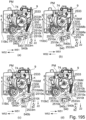
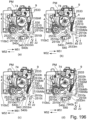
- a laser beam printer which four process cartridges (cartridges) can be mounted to and dismounted from is illustrated as an image forming apparatus.
- the number of process cartridges mounted in the image forming apparatus is not limited to this example. It may be selected as appropriate if necessary.
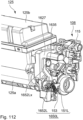
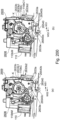
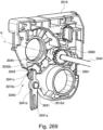
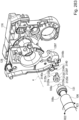
- FIG 2 is a schematic sectional view of the image forming apparatus M.
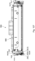
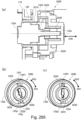
- Figure 3 is a sectional view of the process cartridge 100.
- the image forming apparatus M is a four-color full-color laser printer using an electrophotographic process, and forms a color image on a recording material S.
- the image forming apparatus M is a process cartridge type, in which the process cartridge is dismountably mounted to the image forming apparatus main assembly (apparatus main assembly) 170 to form a color image on the recording material S.
- a side where a front door 11 is provided is a front surface (front surface), and a side opposite to the front surface is a back surface (rear side).
- a right side of the image forming apparatus M as viewed from the front is referred to as a drive-side, and a left side is referred to as a non-drive-side.
- a upper side is a upper surface part, and a lower side is a lower surface part.
- Figure 2 is a sectional view of the image forming apparatus M as viewed from the non-drive-side; the front side of the sheet of the drawing is the non-drive-side of the image forming apparatus M; the right side of the sheet of the drawing is the front side; and the rear side of the sheet of the drawing is the drive-side of the image forming apparatus.
- the drive-side of the process cartridge 100 is the side on which the drum coupling member (photosensitive member coupling member) which will be described hereinafter is provided with respect to an axial direction of the photosensitive drum (the axial direction of the rotation axis of the photosensitive drum).
- the drive-side of the process cartridge 100 is the side on which a development coupling portion 132a, which will be described hereinafter, is provided with respect to the axis direction of the developing roller (development member) (the axial direction of the rotation axis of the developing roller).
- the axial direction of the photosensitive drum and the axial direction of the developing roller are parallel with each other, and the longitudinal direction of the process cartridge 100 is also parallel to these directions.
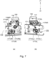
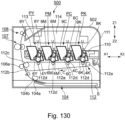
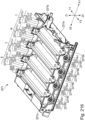
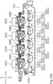
- the image forming apparatus main assembly 170 is provided with four process cartridges 100 (100Y, 100M, 100C, 100K), i.e. A first process cartridge 100Y, a second process cartridge 100M, a third process cartridge 100C, and a fourth process cartridge 100K. It is arranged substantially horizontally.
- Each of the first to fourth process cartridges 100 (100Y, 100M, 100C, 100K) have the same electrophotographic process mechanisms, but the colors of the developers (hereinafter referred to as toner) are different from each other.
- Rotational driving forces are transmitted to the first to fourth process cartridges 100 (100Y, 100M, 100C, 100K) from the drive output portion (details will be described hereinafter) of the image forming apparatus main assembly 170, respectively.
- bias voltages charging bias, development bias, and so on
- each of the first to fourth process cartridges 100 (100Y, 100M, 100C, 100K) of this embodiment includes a drum unit 108 having a photosensitive drum 104 and a charging means as a process means acting on the photosensitive drum 104.
- the drum unit may have a cleaning means as well as the charging means as the process means.
- each of the first to fourth process cartridges 100 (100Y, 100M, 100C, 100K) includes a developing unit 109 having developing means for developing an electrostatic latent image on the photosensitive drum 104.
- the layout of the electrophotographic image forming apparatus in which a plurality of photosensitive drums are arranged substantially in line in this manner is sometimes called an in-line layout or a tandem layout.
- each of the first to fourth process cartridges 100 the drum unit 108 and the developing unit 109 are coupled with each other. A more specific structure of the process cartridge will be described hereinafter.
- the first process cartridge 100Y contains yellow (Y) toner in a developing container 125, and forms a yellow toner image on the surface of the photosensitive drum 104.
- the second process cartridge 100M contains magenta (M) toner in a developing container 125, and forms a magenta toner image on the surface of the photosensitive drum 104.
- the third process cartridge 100C contains cyan (C) toner in a developing container 125, and forms a cyan toner image on the surface of the photosensitive drum 104.
- the fourth process cartridge 100K contains black (K) toner in a developing container 125, and forms a black toner image on the surface of the photosensitive drum 104.
- a laser scanner unit 14 as an exposure means is provided above the first to fourth process cartridges 100 (100Y, 100M, 100C, 100K).
- the laser scanner unit 14 outputs the laser beam U in accordance with image information. Then, the laser beam U passes through an exposure window 110 of the process cartridge 100 to scan and expose the surface of the photosensitive drum 104.
- An intermediary transfer unit 12 as a transfer member is provided below the first to fourth process cartridges 100 (100Y, 100M, 100C, 100K).
- the intermediary transfer unit 12 includes a drive roller 12e, a turn roller 12c, and a tension roller 12b, and a flexible transfer belt 12a extended around them.
- the lower surface of the photosensitive drum of each of the first to fourth process cartridges 100 (100Y, 100M, 100C, 100K) is in contact with the upper surface of the transfer belt 12a.
- the contact portion between them is a primary transfer portion.
- a primary transfer roller 12d is provided so as to oppose the photosensitive drum 104.
- a secondary transfer roller 6 is contacted with the turn roller 12c by way of the transfer belt 12a.
- the contact portion between the transfer belt 12a and the secondary transfer roller 6 is a secondary transfer portion.
- a feeding unit 4 is provided below the intermediary transfer unit 12.
- the feeding unit 4 includes a sheet feed tray 4a on which the recording material S is loaded and accommodated, and a sheet feed roller 4b.
- a fixing device 7 and a sheet discharging device 8 are provided on the upper left side of the image forming apparatus main assembly 170 in Figure 2 .
- the upper surface of the image forming apparatus main assembly 170 is a sheet discharge tray 13.
- the recording material S is heated and pressed by fixing means provided in the fixing device 7, so that the toner image is fixed and discharged to the sheet discharge tray 13.
- the operation for forming a full-color image is as follows.
- the photosensitive drum 104 of each of the first to fourth process cartridges 100 (100Y, 100M, 100C, 100K) is rotationally driven at a predetermined speed (in the direction of arrow A in Figure 3 ).
- the transfer belt 12a is also rotationally driven in a forward direction (direction of an arrow C in Figure 2 ) codirectionally, at the peripheries, with the rotation of the photosensitive drum at a speed corresponding to the speed of the photosensitive drum 104.
- the laser scanner unit 14 is also driven. In synchronism with the drive of the laser scanner unit 14, the charging roller 105 uniformly charges the surface of the photosensitive drum 104 to a predetermined polarity and potential in each process cartridge.
- the laser scanner unit 14 scans and exposes the surface of each photosensitive drum 104 with laser beam U in accordance with the image signals of each color. By this, an electrostatic latent image corresponding to the image signal of the corresponding color is formed on the surface of each photosensitive drum 104.
- the formed electrostatic latent image is developed by a developing roller 106 that is rotationally driven at a predetermined speed.
- a yellow toner image corresponding to a yellow component of the full-color image is formed on the photosensitive drum 104 of the first process cartridge 100Y. Then, the toner image is primary-transferred onto the transfer belt 12a.
- a magenta color toner image corresponding to a magenta component of the full color image is formed on the photosensitive drum 104 of the second process cartridge 100M. Then, the toner image is primary-transferred and superimposed on the yellow toner image already transferred on the transfer belt 12a. Similarly, a cyan toner image corresponding to a cyan component of the full-color image is formed on the photosensitive drum 104 of the third process cartridge 100C. Then, the toner image is primary-transferred and superimposed on the yellow-colored and magenta-colored toner images already transferred on the transfer belt 12a.
- a black toner image corresponding to a black component of the full-color image is formed on the photosensitive drum 104 of the fourth process cartridge 100K. Then, the toner image is primary-transferred and superimposed on the yellow, magenta, and cyan toner images already transferred on the transfer belt 12a. In this manner, an unfixed four-color full-color toner image of yellow, magenta, cyan, and black is formed on the transfer belt 12a.
- the recording material S is separated and fed one by one at a predetermined control timing.
- the recording material S is introduced into the secondary transfer portion, which is a contact portion between the secondary transfer roller 6 and the transfer belt 12a, at a predetermined control timing.
- the four-color superimposed toner image on the transfer belt 12a is sequentially and collectively transferred onto the surface of the recording material S.
- the recording material S is fed to the fixing device 7 to fix the toner image on the recording material S, and then is discharged onto the sheet discharge tray 13.
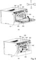
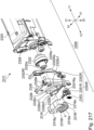
- the tray 171 is movable in a direction indicated by an arrow (pushing direction) and the direction indicated by an arrow X2 (pulling direction) with respect to the image forming apparatus main assembly 170. That is, the tray 171 is provided so as to be retractable and insertable relative to the image forming apparatus main assembly 170, and the tray 171 is structured to be movable in a substantially horizontal direction in a state where the image forming apparatus main assembly 170 is installed on a horizontal surface.
- the state in which the tray 171 is outside the image forming apparatus main assembly 170 (the state shown in Figure 5 ) is referred to as an outside position.
- a state in which the tray is inside the image forming apparatus main assembly 170 with the front door 11 open and the photosensitive drum 104 and the transfer belt 12a being separated from each other is referred to as an inner position.
- the tray 171 is provided with positioning portions 171VR and 171VL for holding the cartridge 100, respectively.
- the positioning portion 171VR has straight portions 171VR1 and 171VR2, respectively.
- the center of the photosensitive drum is determined by arc portions 116VR1 and 116VR2 of the cartridge cover member 116 shown in Figure 7 contacting to the straight portions 171VR1 and 171VR2.
- the tray 171 shown in Figure 7 is provided with a rotational direction position setting projection 171KR.
- the attitude of the process cartridge 100 is determined with respect to the apparatus main assembly 170 by the rotational positioning projection 171KR fitting in the rotational direction position setting recess 116KR of the cartridge cover member 116 shown in Figure 7 .
- the positioning portion 171VL and the rotational direction position setting projection 171KL are arranged at positions (non-drive-side) opposing each other across the intermediary transfer belt 12a in the longitudinal direction of the process cartridge 100 from the positioning portion 171VR. That is, on the non-drive-side as well, the position of the process cartridge is determined by engaging the arc portions 117VL1 and 117VL2 of the cartridge cover member 117 with the positioning portion 171VL and the rotational direction position setting recess 117KL with the rotational direction position setting projection 171KL. By doing so, the position of the process cartridge 100 with respect to the tray 171 is correctly determined.
- the process cartridge 100 integral with the tray 171 is moved in the direction of the arrow X1 and inserted to the position shown in Figure 4 . Then, by closing the front door 11 in the direction of the arrow R, the process carriage 100 is pressed by a cartridge pressing mechanism (not shown) described hereinafter, and is fixed to the image forming apparatus main assembly 170 together with the tray 171. Further, the transfer belt 12a comes into contact with the photosensitive member 4 in interrelation with the operation of the cartridge pressing mechanism. In this state, an image can be formed ( Figure 2 ).
- the positioning portion 171VR and the positioning portion 171VL also function as reinforcements for maintaining stiffness in a pull-out operation of the tray 171, and for this reason, a sheet metal is used, but the present invention is not limited to this example.
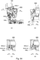
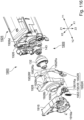
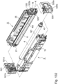
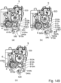
- Part (a) of Figure 8 shows only the process cartridge 100, the tray 171 and cartridge pressing mechanisms 190 and 191 and the intermediary transfer unit 12 in the state of Figure 4 .
- Part (b) of Figure 8 shows only the process cartridge 100, the tray 171 and the cartridge pressing mechanisms and 191 and the intermediary transfer unit 12 in the state of Figure 2 .
- the process cartridge 100 receives a driving force during image formation, and further receives a reaction force from the primary transfer roller 12d ( Figure 2 ) in the direction of arrow Z1. Therefore, it is necessary to press the process cartridge in the Z2 direction in order to maintain a stable attitude during the image forming operation to prevent the process cartridge from separating from the positioning portions 171VR and 171VL.
- the image forming apparatus main assembly 170 is provided with cartridge pressing mechanisms (190, 191).
- a storing element pressing unit 190 works for the non-drive-side
- a cartridge pressing unit 191 works for the drive-side. This will be described in more detail below.
- the storing element pressing unit 190 mainly comprises a main assembly side electric contact (not shown) contactable to the electric contact of the storing element (not shown) provided in the process cartridge 100.
- a link mechanism (not shown)
- the storing element 140 and the electric contact on the main assembly side can be brought into and out of contact with each other. That is, the contacts are brought into contact with each other by closing the front door 11, and the contacts are disconnected by opening the front door 11.
- the storing element pressing unit 190 also function to press the process cartridge 100 against the positioning portion 171VR described above. Further, similarly to the storing element pressing unit 190, the cartridge pressing unit 191 also lowers in the direction of arrow Z2 in interrelation with the operation of closing the front door 11 and function to press the process cartridge 100 against the positioning portion 171VL described above. Further, although the details will be described hereinafter, the cartridge pressing mechanism (190, 191) also functions to push down movable members 152L and 152R of the process cartridge 100 which will be described hereinafter.
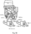
- Part (a) of Figure 9 is a perspective view in which the process cartridge 100 and the tray 171 are omitted in the state of Figure 4 or Figure 5 .
- Part (b) of Figure 9 is a perspective view in which the process cartridge 100, the front door 11 and the tray 171 are omitted in the state of Figure 1 .
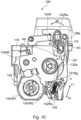
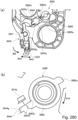
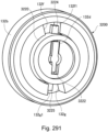
- Figure 10 is a side view of the process cartridge 100 as viewed from the drive-side.
- the process cartridge in this embodiment has a development coupling portion (rotational driving force receiving portion) 132a and a drum coupling member (photosensitive member coupling member) 143.
- a development coupling portion rotational driving force receiving portion
- a drum coupling member photosensitive member coupling member
- the drum drive coupling 180 described above engages with the drum coupling member 143.
- the development drive coupling 185 on the main assembly side engages with the development coupling portion 132a to transmit the drive to the process cartridge 100.
- the drive transmission to the process cartridge 100 is not limitedly effected at two places as described above, and a mechanism for inputting the drive only to the drum coupling to transmit the drive to the developing roller may be provided.
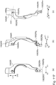
- the intermediary transfer unit 12 of the image forming apparatus main assembly in this embodiment will be described.
- the intermediary transfer unit 12 is raised in the direction of arrow R2 by a link mechanism (not shown) by closing the front door 11 to the position at the time of image formation (the position where the photosensitive drum 104 and the intermediary transfer belt 12a are in contact with each other). Further, by opening the front door 11, the intermediary transfer unit 12 lowers in the direction of arrow R1, and the photosensitive drum 2 and the intermediary transfer belt 12a are spaced from each other. That is, in the state where the process cartridge 100 is set on the tray 171, the photosensitive drum 104 and the intermediary transfer belt 12a are brought into and out of contact with each other by the opening and closing operations of the front door 11.
- the contact/separation operation uses rising and lowering of the intermediary transfer unit with a rotational locus around the center point PV1 shown in Figure 4 .
- the intermediary transfer belt 12a is driven by receiving a force from a gear (not shown) arranged coaxially with the center PV1. Therefore, by setting the above-mentioned position PV1 as the rotation center, the intermediary transfer unit 12 can be raised and lowered without moving the gear center. By doing so, it is unnecessary to move the center of the gear, and the position of the gear can be maintained with high accuracy.
- the photosensitive drum 104 does not slide on the intermediary transfer belt 12a, and therefore, image deterioration which may otherwise be caused by the damaged photosensitive drum 104 and/or the charge memory.
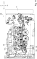
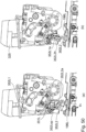
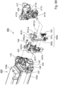
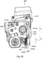
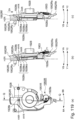
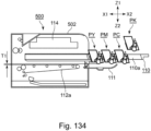
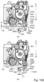
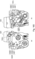
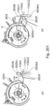
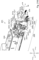
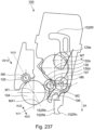
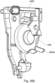
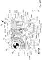
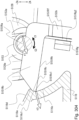
- Figure 11 is a sectional view of the image forming apparatus M taken at a drive-side end portion of the process cartridge 100.
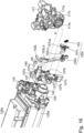
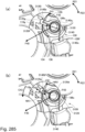
- Figure 12 is a perspective view of the development separation control unit as viewed obliquely from the top.
- a development separation control unit 195 controls spacing and contact operations of the developing unit 109 with respect to the photosensitive drum 104 by engaging with a portion of the developing unit 109.
- the development separation control unit 195 is disposed below the image forming apparatus main assembly 170 as shown in Figure 8 .
- the development separation control unit 195 is arranged below the development coupling portion 132a and the drum coupling member 143 in the vertical direction (downward in the arrow Z2 direction).
- the development separation control unit 195 is arranged adjacent each of opposite ends, in the longitudinal direction (Y1, Y2 direction) of the photosensitive drum, of the intermediary transfer belt 12. That is, the development separation control unit 195 includes a development separation control unit 195R on the drive-side and a development separation control unit 195L on the non-drive-side. By arranging the development separation control unit 195 in dead space of the image forming apparatus main assembly as described above, the main assembly can be downsized.
- the development separation control unit 195R includes four separation control members (force applying members) 196R corresponding to the process cartridge 100 (100Y, 100M, 100C, 100K).
- the four separation control members have substantially the same shape.
- the development separation control unit 195R is always fixed to the image forming apparatus main assembly.
- the separation control member 196R is structured to be movable in the W41 and W42 directions by a control mechanism (not shown).
- the directions W41 and W42 are substantially parallel to an arrangement direction of the process cartridges set in the image forming apparatus main assembly 170. The detailed structure will be described hereinafter.
- the development separation control unit 195L has four separation control members (force applying members) 196L corresponding to the process cartridge 100 (100Y, 100M, 100C, 100K).
- the four separation control members have substantially the same shape.
- the development separation control unit 195L is always fixed to the image forming apparatus main assembly.
- the separation control member 196L is structured to be movable in the W41 and W42 directions by a control mechanism (not shown). The detailed structure will be described hereinafter.
- a portion of a development control unit 196 and a portion of the developing unit are overlapped in the vertical direction (Z1, Z2 direction). Therefore, after the process cartridge 100 is inserted in the X1 direction, a portion of the developing unit (movable member 152 in the case of this embodiment) is required to project in the vertical direction (Z1, Z2 direction) as described above (details will be described hereinafter).
- a development separation control unit 195 itself is raised in the same manner as the above-mentioned intermediary transfer unit 12 for the purpose of such engagement, there are problems such as an increase in the operating force of the interrelated front door 11 and complication of the drive train.
- this embodiment employs a method in which the development separation control unit 195 is fixed to the image forming apparatus main assembly 170, and a portion (movable member 152) of the developing unit 109 is projected downward (Z2) in the image forming apparatus main assembly 170. Further, as for the mechanism for projecting the movable member 152, the mechanisms of the storing element pressing unit 190 and the cartridge pressing unit 191 described above are used as they are, and therefore, there is no problem as described above and no problem of increase in the cost of the apparatus main assembly can be suppressed.
- the unit of the development separation control unit 195 as a whole is fixed to the image forming apparatus main assembly 170. However, in order to engage with the movable member 152 to operate so that the developing unit 109 is spaced (spaced position, retracted position) and contacted (contact position) relative to the photosensitive drum 104, a portion of the development separation control unit 195 has a movable structure. Details will be described hereinafter.
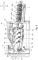
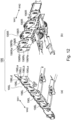
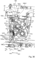
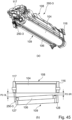
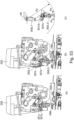
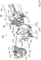
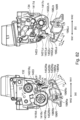
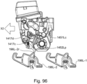
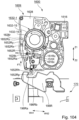
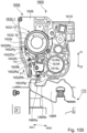
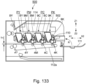
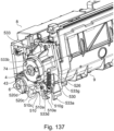
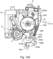
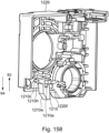
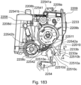
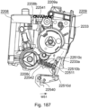
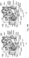
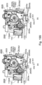
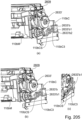
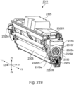
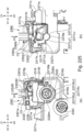
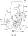
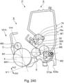
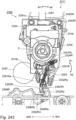
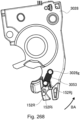
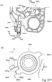
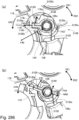
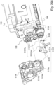
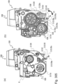
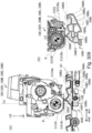
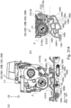
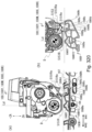
- Figure 13 is an assembly perspective view of the process cartridge 100 as viewed from the drive-side, which is one end side in the axial direction of the photosensitive drum 104.
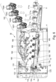
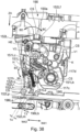
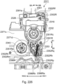
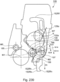
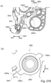
- Figure 14 is a perspective view of the process cartridge 100 as viewed from the drive-side.
- the first to fourth process cartridges 100 may differ in the color of the contained toner, the toner filling amount, and the control by the image forming apparatus main assembly 170.
- these four process cartridges may be different in dimensions and the like, they have the same basic structures and functions, and can perform the same functions. Therefore, one process cartridge 100 will be described as a representative in the following.
- the process cartridge 100 includes the photosensitive drum (photosensitive member) 104 and the process means for acting on the photosensitive drum 104, respectively.
- the process means includes the charging roller 105 as the charging means (charging member) for charging the photosensitive drum 104, and a developing means (development member as the developing roller 106 for developing the latent image formed on the photosensitive drum 104 by depositing toner onto the photosensitive drum 104.
- the developing roller 106 carries the toner on the surface thereof.
- the process cartridge 100 may be provided further with a cleaning blade, a brush, or the like which contacts with the photosensitive drum 104, as the cleaning means (cleaning member) for removing residual toner remaining on the surface of the photosensitive drum 104.
- the discharging means for removing electric charge from the surface of the photosensitive drum 104 the light guide member such as a light guide or a lens for irradiating the photosensitive drum 104 with light, a light source, or the like may be provided.
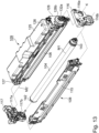
- the process cartridge 100 is divided into a drum unit (first unit) 108 (108Y, 108M, 108C, 108K) and the developing unit (second unit) 109 (109Y, 109M, 109C, 109K).
- the drum unit 108 includes the photosensitive drum 104, the charging roller 105, a first drum frame portion 115, a drive-side cartridge cover member 116 and a non-drive-side cartridge cover member 117 as the second drum frame mounted to the first drum frame portion 115.
- the photosensitive drum 104 is rotatably supported about the rotation axis (rotation center) M1 by the drive-side cartridge cover member 116 and the non-drive-side cartridge cover member 117 provided at both ends in the longitudinal direction of the process cartridge 100.
- the drum frame (first frame) in which the first drum frame portion 115, the drive-side cartridge cover member 116 and the non-drive-side cartridge cover member as the second drum frame portion 117 constitutes the drum frame (first frame or second frame) rotatably supporting the photosensitive drum 104.
- a coupling member 143 for transmitting a driving force to the photosensitive drum 104 is provided on one end side of the photosensitive drum 104 in the longitudinal direction. As described above, the coupling member 143 engages with the main assembly side drum drive coupling (see Figure 9 ) as a drum drive output portion of the image forming apparatus main assembly 170. Then, the driving force of the driving motor (not shown) of the image forming apparatus main assembly 170 is transmitted to the photosensitive drum 104 to rotate it in a direction of arrow A.
- the photosensitive drum 104 is provided with a drum flange 142 on the other end side in the longitudinal direction.
- the charging roller 105 is supported by the drum frame 115 in contact with the photosensitive drum 104 and is driven thereby to rotate.
- the rotation axis M1 is parallel to the longitudinal direction of the process cartridge 100 and the longitudinal direction of the drum unit 108.
- the developing unit 109 includes the developing roller 106, a toner feeding roller (developer agent supply member) 107, a developing blade 130, the developing container 125, and so on.
- the developing container 125 includes a lower frame 125a and a lid member 125b.
- the lower frame 125a and a lid member 125b are connected by ultrasonic welding or the like.
- the developing container 125 which is the second frame, has a toner accommodating portion 129 for accommodating toner to be supplied to the developing roller 106.
- a drive-side bearing 126 and a non-drive-side bearing are mounted and fixed to respective ends of the developing container 125 in the longitudinal direction.
- the developing container 125 rotatably supports the developing roller 106, a toner feeding roller 107, and a stirring member 129a by way of the drive-side bearing and the non-drive-side bearing 127, and holds the developing blade 130.
- the developing container 125, the drive-side bearing 126, and the non-drive-side bearing 127 constitute the developing frame (second frame) that rotatably supports the developing roller 106 about the rotation axis (rotation center) M2.
- the stirring member 129a rotates to stir the toner in the toner accommodating portion 129.
- the toner feeding roller (developer material supply member) 107 contacts the developing roller 106, supplies toner to the surface of the developing roller 106, and also strips the toner off the surface of the developing roller 106.
- the developing blade 130 is formed by mounting an elastic member 130b, which is a sheet-like metal including a thickness of about 0.1 mm, to a supporting member 130a, which is a metal material including an L-shaped cross-section, by welding or the like.
- the developing blade 130 regulates the toner layer thickness (thickness of the toner layer) on the peripheral surface of the developing roller 106 to form a toner layer having a predetermined thickness between the elastic member 130b and the developing roller 106.
- the developing blade 130 is mounted to the developing container 125 with fixing screws 130c at two positions in one end side and the other end side in the longitudinal direction.
- the developing roller 106 comprises a metal core metal 106c and a rubber portion
- the development coupling portion 132a for transmitting the driving force to the developing unit 109 is provided on one end side of the developing unit in the longitudinal direction.
- the development coupling portion 132a engages with the development drive coupling 185 (see Figure 9 ) on the main assembly side as a development drive output portion of the image forming apparatus main assembly 170 to receive the driving force, thereby to rotate the drive motor (not shown) of the image forming apparatus main assembly 170.
- the driving force received by the development coupling portion 132a is transmitted by a driving train (not shown) provided in the developing unit 109, so that the developing roller 106 can be rotated in the direction of arrow D in Figure 3 .
- a development cover member 128 which supports and covers a development coupling portion 132a and a driving train (not shown) is provided on one end side of the developing unit 109 in the longitudinal direction.
- An outer diameter of the developing roller 106 is selected to be smaller than the outer diameter of the photosensitive drum 104.
- the outer diameter of the photosensitive drum 104 in this embodiment is in the range of ⁇ 18 to ⁇ 22 (mm), and the outer diameter of the developing roller 106 is in the range of ⁇ 8 to ⁇ 14 (mm). By selecting the outer diameters in this way, efficient arrangement is accomplished.
- the rotation axis M2 is parallel to the longitudinal direction of the process cartridge 100 and to the longitudinal direction of the developing unit 109.
- the drum unit 108 and the developing unit 109 are connected by a drive-side cartridge cover member 116 and a non-drive-side cartridge cover member 117 provided at opposite ends in the longitudinal direction of the process cartridge 100.
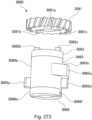
- the drive-side cartridge cover member 116 provided on one end side of the process cartridge 100 in the longitudinal direction is provided with a developing unit supporting hole 116a for swinging (moving) of the developing unit 109.
- the non-drive-side cartridge cover member 117 provided on the other end side of the process cartridge 100 in the longitudinal direction is provided with a developing unit supporting hole 117a for swingably supporting the developing unit 109.
- the drive-side cartridge cover member 116 and the non-drive-side cartridge cover member 117 are provided with drum supporting holes 116b and 117b for rotatably supporting the photosensitive drum 104.
- the outer diameter portion of a cylindrical portion 128b of the development cover member 128 is fitted into the developing unit supporting hole 116a of the drive-side cartridge cover member 116.
- the outer diameter portion of the cylindrical portion (not shown) of the non-drive-side bearing 127 is fitted into the developing unit supporting hole 117a of the non-drive-side cartridge cover member 117.
- the opposite ends of the photosensitive drum 104 in the longitudinal direction are fitted into the drum supporting holes 116b of the drive-side cartridge cover member 116 and drum supporting holes 117b of the non-drive-side cartridge cover member 117.
- the drive-side cartridge cover member 116 and the non-drive-side cartridge cover member are fixed to the drum unit 108 with screws or adhesives (not shown).
- the developing unit 109 is rotatably supported by the drive-side cartridge cover member 116 and the non-drive-side cartridge cover member 117 with respect to the drum unit 108 (photosensitive drum 104).
- the developing roller 106 can be positioned at a place for acting on the photosensitive drum 104 during image formation.
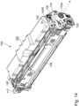
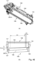
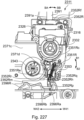
- Figure 14 shows a state in which the drum unit 108 and the developing unit 109 are assembled by the above-described steps and integrated into the process cartridge 100.
- the axis connecting the center of the developing unit supporting hole 116a of the drive-side cartridge cover member 116 and the center of the developing unit supporting hole 117a of the non-drive-side cartridge cover member 117 is called a swing axis (rotation axis, rotation center) K.
- the cylindrical portion 128b of the development cover member on one end side is coaxial with the development coupling portion 132a. That is, the rotation axis of the development coupling portion 132a is coaxial with the swing axis K.
- the swing axis K is also the rotation axis K of the development coupling portion 132a.
- the developing unit 109 is supported rotatably about the swing shaft K.
- the rotation axis M1, the rotation axis M2, and the swing axis K are substantially parallel to each other. Further, in this state, the rotation axis M1, the rotation axis M2, and the swing axis K are substantially parallel to the longitudinal direction of the process cartridge 100, respectively.
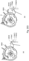
- the process cartridge is provided with a separation/contact mechanism 150R on the drive-side and a separation/contact mechanism 150L on the non-drive-side.
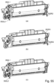
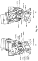
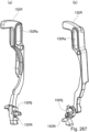
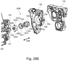
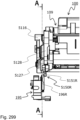
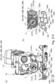
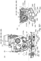
- Figure 15 shows an assembly perspective view of the drive-side of the developing unit 109 including the separation/contact mechanism 150R.
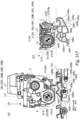
- Figure 16 shows an assembly perspective view of the developing unit including the separation/contact mechanism 150L on the non-drive-side.
- the separation/contact mechanism the details of the separation/contact mechanism 150R on the drive-side will first be described, and then the separation/contact mechanism 150L on the non-drive-side will be described.
- the separation/contact mechanism has almost the same functions on the drive-side and the non-drive-side, and therefore, R is added to the reference numeral of each member on the drive-side.
- the reference numeral of each member is the same as that of the drive-side, and L is added.
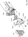
- the separation/contact mechanism 150R includes a spacer R (spacer 151R) which is a restriction member (holding member), a movable member 152R which is a pressing member (force applying member), and a tension spring 153.
- the separation/contact mechanism 150L includes a spacer L (spacer 151L) which is a restricting member, a movable member 152L which is a pressing member (force applying member), and a tension spring 153.
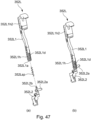
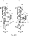
- Part (a) of Figure 17 is a front view of the process cartridge 100 of the spacer 151R per se as viewed from the drive-side longitudinal direction.
- Part (b) of Figure 17 and part (c) of Figure 17 are perspective views of the spacer 151R
- part (d) of Figure 17 is a view of the spacer 151R as viewed in the direction of arrow Z2 in part (a) of Figure 17 (vertically upward in the image forming state).
- the spacer 151R includes an annular supported portion 151Ra, and includes a separation holding portion (holding portion) 151Rb projecting from the supported portion 151Ra in the radial direction of the supported portion 151Ra.
- the free end of the separation holding portion 151Rb includes a contact surface (contact portion)151Rc having an arc shape centered on the swing axis H of the spacer 151R and having an inclination of an angle ⁇ 1 with respect to the line HA substantially parallel to the swing axis H.
- the angle ⁇ 1 is selected so as to satisfy the following inequality (1): 0 ° ⁇ ⁇ 1 ⁇ 45 °
- the separation holding portion (holding portion) 151Rb is a portion which connects the supported portion 151Ra and the contact surface 151Rc, and is sandwiched between the drum unit 108 and the developing unit 109 and has sufficient rigidity to maintain the spaced position.
- the spacer 151R has a restricted surface (restricted portion) 151Rk adjacent to the contact surface 151Rc. Further, the spacer 151R has a restricted surface (restricted portion) 151Rd projecting in the Z2 direction beyond the supported portion 151Ra, and has an arc shape pressed surface (at-contact pressed portion) 151Re projecting from the restricted surface 151Rd in the swing axis H direction of the supported portion 151Ra.
- the spacer 151R includes a main body portion 151Rf connected to the supported portion 151Ra, and the main body portion 151Rf includes a spring-hooked portion 151Rg projecting in the swing axis H direction of the supported portion 151Ra. Further, the main body portion 151Rf has a rotation prevention portion 151Rm projecting in the Z2 direction, and the rotation prevention surface 151Rn is provided in a direction of opposing the pressed surface 151Re.
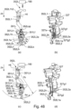
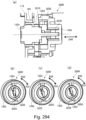
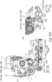
- Figure 18 Part (a) of Figure 18 is a front view of the movable member 152R as viewed in the longitudinal direction of the process cartridge 100, and Figures 18B and 18C are perspective views of the movable member 152R per se.
- the movable member 152R has an oblong-shaped oblong supported portion 152Ra.
- the longitudinal direction of the oblong shape of the oblong supported portion 152Ra is indicated by an arrow LH
- the upper portion is indicated by an arrow LH1
- the lower portion is referred to as an arrow LH2.
- the direction in which the oblong round supported portion 152Ra is formed is indicated by HB.
- the movable member 152R has a projecting portion (force receiving portion) 152Rh formed on the downstream side in the arrow LH2 direction of the oblong supported portion 152Ra.
- the oblong supported portion 152Ra and the projecting portion 152Rh are connected by a main body portion 152Rb.
- the movable member 152R includes a pressed portion 152Re projecting in the direction of the arrow LH1 direction and the direction substantially perpendicular to the direction of arrow LH1, an arc-shaped pressed surface 152Rf (moving force receiving portion, operating force receiving portion) on the downstream side in the arrow LH1 direction, and a pressing-restricting surface 152Rg on the upstream side.
- the movable member 152R has a first restricted surface (first restricted portion) 152Rv extending from the main body portion 152Rb toward the upstream side in the arrow LH2 direction with respect to the projecting portion 152Rh. Further, the movable member 152R has a second restricted surface 152Rw adjacent to the first restricted surface 152Rv and substantially parallel to the developing frame pressing surface (developing frame pressing portion, second frame pressing portion) 152Rq.
- the projecting portion 152Rh includes a first force receiving portion (retracting force receiving portion, separating force receiving portion) 152Rk and a second force receiving portion (contact force receiving portion) 152Rn) arranged at the end in the arrow LH2 direction and in a direction substantially perpendicular to the arrow LH2 direction.
- the first force receiving portion 152Rk and the second force receiving portion 152Rn includes an arc shape first force receiving surface (retracting force receiving surface and the separating force receiving surface) 152Rm and a second force receiving surface (contact force receiving surface 152Rp) extending in the HB direction.
- the projecting portion 152Rh has a spring-hooked portion 152Rs projecting in the H direction and a locking portion 152Rt, and the locking portion 152Rt has a locking surface 152Ru opposing in the same direction as the second force receiving surface 152Rp.
- the movable member 152R is a part of the main body portion 152Rb, is arranged on the upstream side in the arrow LH2 direction with respect to the second force receiving portion 152Rn, and has a developing frame pressing surface 152Rq facing the same direction as the second force receiving surface 152Rp. Further, the movable member 152R has a spacer pressing surface (pressing portion) 152Rr which is perpendicular to the first restricted surface 152Rv and is arranged to oppose the developing frame pressing surface 152Rq.
- the LH1 direction is substantially the same as the Z1 direction
- the LH2 direction is substantially the same as the Z2 direction
- the HB direction is substantially the same as the longitudinal direction of the process cartridge 100.
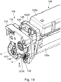
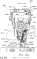
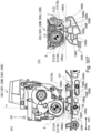
- Figure 19 is a perspective view of the process cartridge 100 after assembling the spacer 151R as viewed from the drive-side.
- the outer diameter portion of the cylindrical portion 128b of the development cover member 128 is fitted into a developing unit supporting hole portion 116a of the drive-side cartridge cover member 116.
- the developing unit 109 is supported rotatably about the swing axis K relative to the photosensitive drum 104.
- the development cover member is provided with a cylindrical first supporting portion 128c and a second supporting portion 128k projecting in the direction of the swing axis K.
- the outer diameter of the first supporting portion 128c fits with an inner diameter of the supported portion 151Ra of the spacer 151R, and rotatably supports the spacer 151R.
- a swing center of the spacer 151R assembled to the development cover member 128 is defined as the swing axis H.
- the development cover member 128 is provided with a first retaining portion 128d which projects in the direction of the swing axis H. As shown in Figure 15 , the movement of the spacer 151R assembled to the development cover member 128 in the swing axis H direction is restricted by the contact of the first retaining portion 128d to the spacer 151R.
- the outer diameter of the second supporting portion 128k fits with an inner wall of the oblong supported portion 152Ra of the movable member 152R, and supports the movable member 152R so as to be rotatable and movable in the length direction of the oblong direction.
- the swing center of the movable member 152R assembled to the development cover member 128 is referred to as a movable member swing axis HC of the movable member.
- the movement of the movable member 152R assembled to the development cover member 128 in the swing axis HC direction is restricted by the contact of a second retaining portion 128m to the spacer 151R.
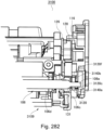
- Figure 10 is a sectional view in which a portion of the drive-side cartridge cover member 116 and a portion of the development cover member 128 are omitted in a sectional line CS so that the fitting portion between the oblong supported portion 151Ra of the movable member 152R and the cylindrical portion 128b of the development cover member 128 can be seen.
- the separation/contact mechanism 150R includes the tension spring 153 provided with a spacer portion urging portion (holding portion urging portion) which urges the spacer 151R to rotate in the direction of arrow B1 in the drawing about the swing shaft H, and provided with a force receiving portion urging portion (projecting portion urging portion) for urging the movable member 152R is in the B3 direction indicated by an arrow.
- the tension spring 153 is a coil spring which is an elastic member.
- the arrow B3 direction is a direction substantially parallel to the long circle extending longitudinal direction LH2 (see Figure 18 ) of the oblong round supported portion 152Ra of the movable member 152R.
- the tension spring 153 is engaged with and connected with the spring-hooked portion 151Rg provided on the spacer 151R and the spring-hooked portion 152Rs provided on the movable member 152R, and is assembled between them.
- the tension spring 153 applies a force to the spring-hooked portion 151Rg of the spacer 151R in the direction of arrow F2 in Figure 10 to apply an urging force to rotate the spacer 151R in the direction of arrow B1.
- the tension spring 153 applies a force to the spring-hooked portion 152Rs of the movable member 152R in the direction of the arrow F1 to move the movable member 152R in the direction of the arrow B3 (direction toward the accommodating position (reference position, stand-by position)).
- the line GS is a line connecting the spring-hooked portion 151Rg of the spacer 151R and a spring-hooked portion 152Rs of the force holding member 152R
- the line HS is a line connecting the spring-hooked portion 152Rs of the movable member 152R and the movable member swinging axis HC.
- An angle ⁇ 2 formed by the line GS and the line HS is selected so as to satisfy the following inequality (2) with the clockwise direction centered on the spring-hooked portion 152Rs of the movable member 152R as positive.
- the movable member 152R is urged to rotate in the direction of arrow BA with the movable member swing axis HC as the center of rotation. 0 ° ⁇ ⁇ 2 ⁇ 90 °
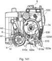
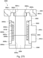
- the development drive input gear (development coupling member) 132 provided with the development coupling portion 132a, an inner diameter portion of the cylindrical portion 128b of the development cover member 128 and an outer circumference of a cylindrical portion 32b of the development drive input gear 132 are fitted, and in addition, a support portion 126a of the drive-side bearing 126 and the cylindrical portion (not shown) of the development drive input gear 132 are fitted.
- the development drive input gear 132 is rotatably supported around the rotation axis K.
- the developing roller gear 131 is fixed to the drive-side end of the developing roller 106, and a toner feeding roller gear 133 is fixed to the drive-side end of the toner feeding roller (developer supply member) 107.
- the spacer 151R and the movable member 152R in the direction of the swing axis K will be described.
- the spacer 151R is provided on the side where the drive-side cartridge cover member 116 is disposed (outside in the longitudinal direction) with respect to with the development cover member 128, and the movable member 152R is provided on the side (inside in the longitudinal direction) where the development drive input gear 132 is disposed.
- the positional arrangement is not limited to this example, and the positions of the spacer 151R and the movable member 152R may be interchanged, or the spacer 151R and the movable member 152R may be arranged on one side with respect to the development cover member 128 in the swing axis K direction. Further, the arrangement order of the spacer 151R and the movable member 152R may be exchanged.
- the development cover member 128 is fixed to the developing container 125 by way of the drive-side bearing 126 to form the developing unit 109.
- the fixing method in this embodiment uses a fixing screw 145 and an adhesive (not shown), but the fixing method is not limited to this example, and welding such as welding by heating or pouring and hardening of resin may be used.
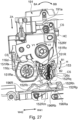
- Figure 20 is a sectional view in which a periphery of the separation holding portion 151R in Figure 10 is enlarged, and a part of the tension spring 153 and the spacer 151R is partially omitted on the partial sectional line CS4 for the sake of better illustration.
- the first restricted surface 152Rv of the movable member 152R comes into contact with a first restricted surface 128h of the development cover member 128 by the urging force of the tension spring 153 in the F1 direction in the drawing.
- the second restricted surface 152Rw of the movable member 152R comes into contact with a second restricted surface 128q of the development cover member 128 and is positioned.
- This position is referred to as an accommodated position for the movable member 152R and the projecting portion 152Rh.
- the accommodated position can also be referred to as a reference position or a stand-by position.
- the spacer 151R is rotated in the B1 direction about the swing axis H by the urging force of the tension spring 153 in the F2 direction, and the restricted surface 151Rd of the spacer 151R is brought into contact with the spacer pressing surface 152Rr of the movable member 152R to stop the rotation.
- This position is referred to as a separation holding position (restriction position, first position) of the spacer 151R.
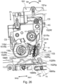
- Figure 21 is an illustration in which the periphery of the separation holding portion 151R in Figure 10 is enlarged, and the tension spring 153 is omitted for better illustration.
- the case will be considered in which the process cartridge 100 including the separation/contact mechanism 150R of this embodiment is dropped in the JA direction in Figure 21 when the process cartridge 100 is transported.
- the spacer 151R receives a force tending to rotate in the direction of arrow B2 due to its weight around the separation holding swing shaft H.
- the tension spring 153 is used as the urging means for urging the spacer 151R to the separation holding position and the movable member 152R to the accommodated position, but the urging means is not limited to this example.
- a torsion coil spring, a leaf spring, or the like may be used as an urging means to urge the movable member 152R to the accommodated position and the spacer 151R to the separation holding position.
- the material of the urging means may be metal, a mold, or the like, if it has elasticity and can urge the spacer 151R and the movable member 152R.
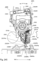
- the developing unit 109 provided with the separation/contact mechanism 150R is integrally coupled with the drum unit 108 by the drive-side cartridge cover member 116 as described above (state in Figure 19 ).
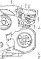
- Figure 22 is a view as seen in the direction of arrow J in Figure 19 .
- the drive-side cartridge cover member 116 of this embodiment has a contacted surface (contact portion) 116c.
- the contacted surface 116c is formed with an inclination of an angle ⁇ 3 with respect to the swing axis K.
- the angle ⁇ 3 is preferably the same as the angle ⁇ 1 forming the contact surface 151Rc of the spacer 151R, but is not limited to such.
- the contacted surface 116c is opposed to the contact surface 151Rc of the spacer 151R placed at the separation holding position when the drive-side cartridge cover 116 is assembled to the developing unit 109 and the drum unit 108. Further, the contacted surface 116c contacts the contact surface 151Rc by the urging force of the development pressure spring 134 which will be described hereinafter.
- the attitude of the developing unit 109 is determined so that the developing roller 106 of the developing unit 109 and the photosensitive drum 104 are separated by a gap P1.
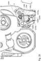
- the state in which the developing roller 106 (developing member) is spaced from the photosensitive drum 104 by the gap P1 by the spacer 151R is referred to as a spaced position (retracted position) of the developing unit 109 (see part (a) of Figure 1 ).
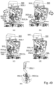
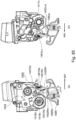
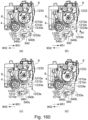
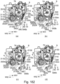
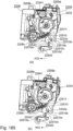
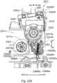
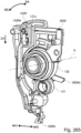
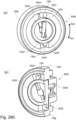
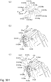
- Figure 1 is a side view of the process cartridge 100 as viewed from the drive-side with the process cartridge 100 mounted inside the image forming apparatus main assembly 170.
- Part (a) of Figure 1 shows a state in which the developing unit 109 is separated from the photosensitive drum 104.
- Part (b) of Figure 1 shows a state in which the developing unit 109 is in contact with the photosensitive drum 104.
- the spacer 151R is in the separation holding position (first position) and the developing unit 109 is in the separation position (retracted position)
- the supported portion 151Ra which is one end of the separation holding portion 151Rb contacts the first supporting portion 128c of the development cover member 128, and the contact portion 151Rc which is the other end contacts the contacted surface 116c of the drive-side cartridge cover member 116.
- the first supporting portion 128c is pressed toward the supported portion 151Ra by the action of the development pressure spring 134, and the contact portion 151Rc is pressed toward the contacted surface 116c.
- this state is a state in which the drive-side cartridge cover member 116 positions the development cover member 128 by way of (sandwiching) the separation holding portion 151Rb of the spacer 151R and stably holds the development cover member 128. That is, it can be said that the drum unit 108 is positioned and stably hold it by the developing unit 109 by way of the spacer 151R.
- the pressed portion 152Re of the movable member 152R is pushed in the ZA direction.
- the movable member 152R and the projecting portion 152Rh move linearly from the stand-by position in the ZA direction (operating direction, predetermined direction) to reach the projecting position.
- the ZA direction is parallel to the rotation axis M2 of the developing roller 106 or the rotation axis M1 of the photosensitive drum 108. Therefore, the projecting portion 152Rh when in the projecting position is arranged downstream in the ZA direction from the projecting portion 152Rh when in the stand-by position.
- the projecting portion 152Rh placed in the projecting position is located more remote from the swing axis K than the projecting portion 152Rh placed in the stand-by position. Further, the projecting portion 152Rh placed at the projecting position projects in the ZA direction from the drum frame and the developing frame (arranged downstream in the ZA direction).
- the drum frame includes the first drum frame portion 115, the drive-side cartridge cover member 116, and the non-drive-side cartridge cover member 117
- the developing frame includes the developing container 125 and the drive-side bearing 126 and the non-drive-side bearing 127.
- the ZA direction is the direction crossing with the direction in which the four process cartridges 100 are arranged, the W41 direction, and the W42 direction.
- the attitude shown in Figure 1 is also the attitude in which the rotation axis M1 of the photosensitive drum 104 is horizontal and the photosensitive drum 104 is arranged at the lower portion in the process cartridge 100 when the vertical direction in the Figure is the vertical direction.
- the projecting portion 152Rh projects downward by projecting in the ZA direction.
- Figures 26 and 38 show the attitude of the process cartridge 100 in a state of being mounted in the image forming apparatus main assembly 170, and the vertical direction in the drawing is the vertical direction (Z1 direction, Z2 direction) when the image forming apparatus main assembly 170 is installed on a horizontal surface.
- the ZA direction vector in this attitude is a vector including at least a vertical component. Therefore, even in this attitude, it can be said that the projecting portion 152Rh projects downward by projecting in the ZA direction.
- the movable member 152R can move in the ZA direction and the direction opposite thereto while maintaining the state that the spacer 151R is in the separation holding position (first position). Therefore, even when the movable member 152R and the projecting portion 152Rh are in the operating position, the spacer 151R is located in the separation holding position (first position). At this time, the pressed surface 151Re of the spacer 151R is in contact with the spacer pressing surface 152Rr of the movable member 152R by the tension spring 153 as described above.
- the movable member 152R rotates in the direction of the arrow BB about the movable member swing axis HC, and the spacer pressing surface 152Rr presses the restricted portion 151Rd, by which the spacer 151R is rotated in the direction of arrow B2.
- the contact surface 151Rc separates from the contacted surface 116c, and the developing unit 109 can rotate in the direction of arrow V2 about the swing axis K from the separated position.
- the position of the developing unit 109 in which the developing roller 106 and the photosensitive drum 104 are in contact with each other is referred to as a contact position (development position) (state of part (b) of Figure 1 .
- the contact position (development position) in which the developing roller 106 is in contact with the photosensitive drum 104 is not only the position where the surface of the developing roller 106 is in contact with the surface of the photosensitive drum 104, but the position where the toner carried on the surface of the photosensitive drum 104 can contact the surface of the photosensitive drum 104 when the developing roller 106 rotates is also included.
- the contact position is a developing position where the toner carried on the surface of the developing roller 106 can be transferred (deposited) to the surface of the photosensitive drum 104 when the developing roller 106 rotates.
- the position where the contact surface 151Rc of the spacer 151R is spaced from the contacted surface 116c is referred to as a separation release position (permitted position, second position).
- the restriction surface 151Rk of the spacer 151R is in contact with the spacer restriction surface (spacer portion restriction portion) 116d of the drive-side cartridge cover 116.
- the spacer 151R is constrained from moving to the separation holding position and is maintained at the separation release position.
- the drive-side bearing 126 has a first pressed surface (at-separation pressed portion) 126c which is a surface perpendicular to the swing axis K.
- the drive-side bearing is fixed to the developing unit 109. Therefore, when the developing unit 109 presses the first force receiving portion 152Rk of the movable member 152R in the direction of an arrow 41 when the developing unit 109 is in the contact position, the developing frame pressing surface 152Rq comes into contact with the first pressed surface 126c. By this, the developing unit 109 rotates about the swing axis K in the direction of the arrow V1 to move to the separated position (retracted position) (state of part (a) of Figure 1 .
- the direction in which the first force receiving surface 126c moves is shown by arrow W41 in part (a) of Figure 1 and part (b) of Figure 1 .
- the direction opposite to the arrow W41 is indicated by arrow W42, and the direction of the arrow W41 and the direction of the arrow W42 are substantially horizontal directions (X1, X2 directions).
- the second force receiving surface 152Rp of the movable member 152R assembled to the developing unit 109 as described above is placed on the upstream side of the first force receiving surface 126c of the drive-side bearing 126 in the arrow W41 direction.
- first force receiving surface 126c and the pressed surface 151Re of the spacer 151R are arranged at positions where at least a portion of them overlap in the W1 and W2 directions.
- the detailed operation of the separation/contact mechanism 150R in the image forming apparatus main assembly 170 will be described below.
- FIGS. 12 , 23 , and 24 engaging operation of 195 will be described between the separation/contact mechanism 150R of the process cartridge 100 and the development separation control unit 195 of the image forming apparatus main assembly 170 at the time when the process cartridge 100 is mounted on the image forming apparatus main assembly 170.
- FIGS are cross-sectional views in which a portion of the development cover member 128 and a portion of the drive-side cartridge cover member 116 are partially omitted along the partial cross-sectional lines CS1 and CS2, respectively.
- Figure 23 is a view as seen from the drive-side of the process cartridge 100 when the process cartridge 100 is mounted on the cartridge tray 171 (not shown) of the image forming apparatus M, and the cartridge tray 171 is inserted into the first mounting position.
- portions other than the process cartridge 100, the cartridge pressing unit 191 and the separation control member 196R are omitted.
- the image forming apparatus main assembly 170 of this embodiment has separation control members 196R corresponding to respective process cartridge 100 as described above.
- the separation control member 196R is disposed on the lower surface side of the image forming apparatus main assembly 170 with respect to the spacer 151R when the process cartridge 100 is placed at a first inner position and a second inner position.
- the separation control member 196R includes a first force application surface (force applying portion, contact force applying portion) 196Ra and a second force application surface (retracting force applying portion, separating force applying portion) 196Rb which project toward the process cartridge 100 and face each other through the space 196Rd.
- the first force application surface 196Ra and the second force application surface 196Rb are connected with each other by a connecting portion 196Rc on the lower surface side of the image forming apparatus main assembly 170.
- the separation control member 196R is rotatably supported by the control sheet metal 197 with the rotation center 196Re as the center of rotation.
- the separating member 196R is normally urged in the E1 direction by an urging member 196R.
- the control sheet metal 197 being structured to be movable in the W41 and W42 directions by a control mechanism (not shown), the separation control member 196R is structured to be movable in the W41 and W42 directions.
- the cartridge pressing unit 191 lowers in the direction of arrow ZA in interrelation with the transition of the front door 11 of the image forming apparatus main assembly 170 from the open state to the closed state, and a first force applying portion 191a comes into contact with the pressed surface 152Rf of the movable member 152R. Thereafter, when the cartridge pressing unit 191 is lowered to a predetermined position which is the second mounting position, the projecting portion 152Rh of the movable member 152R moves in the ZA direction (operating direction, predetermined direction) and projects downward in the Z2 direction of the process cartridge 100 (state of Figure 24 ).
- the ZA direction is a direction intersecting (orthogonally in this embodiment) the rotation axis M2 of the developing roller 106, the rotation axis M1 of the photosensitive drum 108 and the swing axis HC.
- This position is referred to as projecting positions of the movable member 152R and the projecting portion 152Rh.
- the projecting position can also be referred to as a force receiving position or an operating position.
- the projecting portion 152Rh projects more from the developing frame when it is in the projecting position than when it is in the stand-by position.
- a gap T4 is formed between the first force application surface 196Ra of the separation control member 196R and the second force receiving surface 152Rp of the movable member 152R, and a gap T3 is formed between the second force application surface 196Rb and the first force receiving surface 152 Rm. Then, it is located at the second mounting position where the separation control member 196R does not act on the movable member 152R. It can be said that this position of the separation control member 196R is a home position.
- the second force receiving surface 152Rp of the movable member 152R and the first force application surface 196Ra of the separation control member 196R are arranged so as to partially overlap with each other in the W41 and W42 directions.
- the first force receiving surface 152Rm of the movable member 152R and the second force application surface 196Rb of the separation control member 196R are arranged so as to partially overlap in the W41 and W42 directions.
- the development coupling 32 receives a driving force from the image forming apparatus main assembly 170 in the direction of arrow V2 in Figure 24 , so that the developing roller 106 rotates. That is, the developing unit 109 including the development coupling 32 receives torque (driving torque) in the arrow V2 direction about the swing axis K from the image forming apparatus main assembly 170.
- driving torque driving torque
- the separation control member 196R of this embodiment is structured to be movable in the arrow W42 direction of in Figure 24 from the home position.
- the second force application surface 196Ra of the separation control member 196R and the second force receiving surface 152Rp of the second force receiving portion 152Rn of the movable member 152R come into contact with each other, so that the movable member 152R rotates in the BB direction with the movable member swing axis HC as the center of rotation.
- the contact between the first force application surface 196Ra and the second force receiving surface 152Rp is not necessarily surface contact, and may be line contact or point contact.
- the first force application surface 196Ra applies a contact force to the second force receiving surface 152Rp.
- the moving direction of the projecting portion 152Rh when the movable member 152R is rotated in the BB direction is referred to as a first direction.
- the spacer 151R is rotated in the B2 direction while the spacer pressing surface 152Rr of the movable member 152R is in contact with the pressed surface 151Re of the spacer 151R.
- the spacer 151R is rotated by the movable member 152R to the separation release position (second position) where the contact surface 151Rc and the contacted surface 116c are separated from each other.
- the position of the separation control member 196R for moving the spacer 151R to the separation release position (second position) shown in Figure 25 is referred to as a first position.
- the developing unit 109 rotates in the V2 direction by the drive torque received from the image forming apparatus main assembly 170 and the development pressure spring (biased portion) 134 which will be described hereinafter. Then, the developing unit 109 moves to the contact position where the developing roller 106 and the photosensitive drum 104 contact each other (state in Figure 25 ). At this time, the spacer 151R urged in the direction of arrow B1 by the tension spring 153 is maintained at the separation release position (second position) by the restricted surface 151Rk contacting to the spacer restriction surface 116d of the drive-side cartridge cover member 116.
- the separation control member 196R moves in the direction of W41 and returns to the home position.
- the movable member 152R is rotated in the BA direction by the tension spring 153, and the state is shifted such that the developing frame pressing surface 152Rq of the movable member 152R and the first pressing surface 126c of the drive-side bearing 126 are in contact with each other is reached (state shown in Figure 26 ).
- the movable member 152R and the projecting portion 152Rh are in the operating position.
- the separation control member 196R by the movement of the separation control member 196R from the home position to the first position, the force is applied to the movable member 152R, so as to rotate the movable member 152R and move the spacer 151R to the separation release position (second position) from the separation holding position (first position).
- This makes it possible for the developing unit to move from the separated position to the contacting position where the developing roller 9 and the photosensitive drum 104 are in contact with each other.
- the contact force applied from the separation control member 196R is transmitted to the spacer 151R by way of the movable member 152R to move the spacer 151R from the separation holding position (first position) to the separation release position (second position), by which the developing unit 109 is moved from the spaced position (retracted position) to the contact position (developed position).
- the photosensitive drum can be said to be a positioning portion (second positioning portion) which determines the position of the developing unit 109 at the developing position relative to the drum unit 108. Further, at this time, it can be said that the developing unit 109 is stably held by the drum unit 108. At this time, the spacer 151R in the separation release position is not directly contributable to the positioning of the developing unit 109.
- the spacer 151R does not prevent (permits) the developing roller 106 from contacting the photosensitive drum 104 and determining the position of the developing unit 109 relative to the drum unit 108 by moving from the separation holding position to the separation release position. That is, it can be said that the spacer 151R at the separation release position (second position) creates a situation in which the drum unit 108 can stably hold the developing unit 109 at the contact position (development position).
- the position of the developing unit 109 with respect to the drum unit 108 may be determined by way of the spacer 151R as long as the developing roller 106 is in contact with the photosensitive drum 104.
- a surface different from the contact portion 151Rc of the spacer 151R may be brought into contact with the drive-side cartridge cover member 116, and the development cover member 128 may be positioned by the drive-side cartridge cover member 116 by way of the spacer 151R (sandwiched), for example.
- the first force applying portion 191a rises in the direction opposite to the arrow ZA direction.
- the movable member 152R moves in the direction opposite to the arrow ZA direction by the action of the urging member 153.
- the spacer 151R still maintains the separation release position, and the developing unit 109 also maintains the developing position.
- FIGS. 26 and 27 are cross-sectional views in which a portion of the development cover member 128, a portion of the drive-side cartridge cover member 116, and a portion of the drive-side bearing 126 are partially omitted in the partial cross-sectional line CS, respectively.
- the separation control member 196R in this embodiment is structured to be movable from the home position in the W41 direction in Figure 26 .
- the separation control member 196R moves in the W41 direction
- the second force application surface 196Rb and the first force receiving surface 152Rm of the first force receiving portion 152Rk of the movable member 152R come into contact with each other, and the movable member 152R rotates in the direction of arrow BA about the swing axis HC for the movable member.
- the contact between the second force application surface 196Rb and the first force receiving surface 152Rm is not necessarily surface contact, but may be line contact or point contact. In this manner, the second force application surface 196Rb applies a separating force (retracting force) to the first force receiving surface 152Rm.
- the moving direction of the projecting portion 152Rh at the time when the movable member 152R is rotated in the BA direction is referred to as a second direction.
- the developing unit 109 rotates from the contact position in the direction of the arrow V1 about the swing axis K (State of Figure 27 ).
- the pressed surface 152Rf of the movable member 152R forms an arc shape, and the center of the arc is disposed so as to be aligned with the swing axis K.
- the rotation of the developing unit 109 in the arrow V1 direction is not hindered.
- the restricted surface 151Rk of the spacer 151R and the spacer restriction surface 116d of the drive-side cartridge cover member 116 are separated, and the spacer 151R rotates in the direction of arrow B1 (direction from the separation release position to the separation holding position) by the urging force of the tension spring 153.
- the spacer 151R rotates until the pressed surface 151Re contacts spacer pressing surface 152Rr of the movable member 152R, and by this contacting, it shifts to the separation holding position (first position).
- a gap T5 is formed between the contact surface 151Rc and the contacted surface 116Rc as shown in Figure 27 .
- the position shown in Figure 27 in which the developing unit 109 is rotated from the contact position toward the separation position, and the spacer 151R can move to the separation holding position is referred to as a second position of the separation control member 196R.
- the separation control member 196R moves in the arrow W42 direction and returns from the second position to the home position. Then, while the spacer 151R is maintained in the separation holding position, the developing unit 109 is rotated in the arrow V2 direction by the driving torque received from the image forming apparatus main assembly 170 and the development pressure spring 134 described hereinafter, and the contact surface 151Rc contacts the contacted surface 116c. That is, the developing unit 109 is in a state where the separated position is maintained by the spacer 151R, and the developing roller 106 and the photosensitive drum 104 are spaced by the gap P1 (states in Figure 24 and part (a) of Figure 1 .
- the developing unit 109 is constrained by the spacer 151R from moving to the contact position against the driving torque received from the image forming apparatus main assembly 170 and the urging force in the arrow V2 direction due to the urging of the development pressure spring 134, and the developing unit 109 is maintained in a separated position. At this time, it can be said that the developing unit 109 is stably held in a separated position (retracted position) by the drum unit 108.
- the above-mentioned gaps T3 and T4 are formed again, and are located at positions where the separation control member 196R does not act on the movable member 152R (state shown in Figure 24 ). The transition from the state of Figure 27 to the state of Figure 24 is executed without a delay.
- the spacer 151R moves from the separation release position to the separation holding position by moving the separation control member 196R from the home position to the second position. Then, by the separation control member 196R returning from the second position to the home position, the developing unit 109 becomes in a state of maintaining the separation position by the spacer 151R. In this manner, the separation force applied from the separation control member 196R is transmitted to the first pressed surface 126c of the drive-side bearing (portion of the development frame) 126 by way of the movable member 152R, so that the developing unit is moved from the contact position to the separation position (retracted position), and the spacer 151R is moved from the separation release position to the separation holding position.
- the position of the developing unit 109 with respect to the drum unit 108 is determined by being urged in the V2 direction by the driving torque received from the image forming apparatus main assembly 170 and the development pressure spring 134 in the state that the supported portion 151Ra is in contact with the first supported portion 128c, and the contact portion 151Rc is in contact with the contacted surface 116c, as described above. Therefore, the contacted surface 116c can be said to be a positioning portion (first positioning portion) for positioning the developing unit 109 at the separated position (retracted position). At this time, it can be said that the developing unit 109 is stably held by the drum unit 108. Further, it can be said that the spacer 151R at the separation holding position (first position) establishes a situation in which the drum unit 108 can stably hold the developing unit at the separation position (retracted position).
- the first force applying portion 191a rises in the direction opposite to the arrow ZA direction.
- the movable member 152R moves in the direction opposite to the arrow ZA direction by the action of the urging member 153.
- the spacer 151R still maintains the separation holding position, and the developing unit 109 also maintains the separation position.
- Part (a) of Figure 28 is a front view of the spacer 151L of as viewed in the longitudinal direction of the drive-side of the process cartridge 100
- part (b) of Figure 28 and part (c) of Figure 28 are perspective views of the spacer 151L per se.
- the spacer 151L is provided with the annular supported portion 151La, and is provided with a separation holding portion (holding portion) 151Lb projecting from the supported portion 151La in the radial direction of the supported portion 151La.
- the free end of the separation holding portion 151Lb has an arc-shaped contact surface (contact portion) 151Lc centered on the swing shaft H of the spacer 151L.
- the swing shaft H of the spacer 151L is the same as the swing shaft H of the spacer 151R.
- the separation holding portion (holding portion) 151Lb is a portion which connects the supported portion 151La and the contact surface 151Lc with each other, and is sandwiched between the drum unit 108 and the developing unit 109 and has sufficient rigidity to maintain the separating position.
- the spacer 151L has a restricted surface (restricted portion) 151Lk adjacent to the contact surface 151Lc. Further, the spacer 151L has a restricted portion 151Ld projecting in the Z2 direction from the supported portion 151La, and has an arc-shaped pressed portion 151Le (at-contact pressed portion) projecting from the restricted portion 151Ld in the direction of the swing axis H of the supported portion 151La.
- the spacer 151L has a main body portion 151Lf connected to the supported portion 151La, and the main body portion 151Lf is provided with a spring-hooked portion 151Lg projecting in the swing axis H direction of the supported portion 151La. Further, the main body portion 151Lf has a rotation prevention portion 151m projecting in the Z2 direction, and a rotation prevention surface 151Ln is provided in a direction opposing the pressed portion 151Le.
- Part (a) of Figure 29 is a front view of the movable member 152L per se as viewed from the longitudinal direction of the process cartridge 100, and part (b) of Figure 29 and part (c) of Figure 29 are perspective views of the movable member 152L.
- the movable member 152L is provided with the oblong supported portion 152La.
- the longitudinal direction of the oblong shape of the oblong supported portion 152La is referred to as an arrow LH
- the upward direction is referred to as an arrow LH1
- the downward direction is referred to as an arrow LH2.
- the direction in which the oblong supported portion 152La is formed is defined as HD.
- the movable member 152L is provided with the projecting portion (force receiving portion) 152Lh formed on the downstream side, in the arrow LH2 direction, of the oblong supported portion 152La.
- the oblong supported portion 152La and the projecting portion 152Lh are connected with each other by the main body portion 152Lb.
- the movable member 152L is provided with a pressed portion 152Le projecting in the direction substantially perpendicular to the direction of arrow LH1, and an arc-shaped pressed surface (moving force receiving portion, operating force receiving portion) 152Lf at a position downstream in the arrow LH1 direction, a push-restricting surface 152Lg on the upstream side.
- the movable member 152L has a first restricted surface (first restricted portion) 152Lv which is a portion of the oblong supported portion 152La and which is located on the downstream side in the arrow LH2 direction.
- the projecting portion 152Lh is a first force receiving portion (retracting force receiving portion, separating force receiving portion) 152Lk and a second force receiving portion (contact force receiving portion) 152Ln which are provided opposed to each other in a direction substantially perpendicular to the arrow LH2 direction, at the end in the arrow LH2 direction.
- the first force receiving portion 152Lk and the second force receiving portion 152Ln are provided with a first force receiving surface (retracting force receiving surface, a separating force receiving surface) 152Lm and a second force receiving surface (contact force receiving surface) 152L Page which extend in the HD direction and which have arc shapes, respectively.
- the projecting portion 152Lh is provided with a spring-hooked portion 152Ls projecting in the HB direction and a locking portion 152Lt, and the locking portion 152Lt is provided with a locking surface 152Lu facing in the same direction as the second force receiving surface 152Lp.
- the movable member 152L is a part of the main body portion 152Lb, is disposed on the upstream side in the arrow LH2 direction from the second force receiving portion 152Ln, and has a developing frame pressing surface (developing frame pressing portion, at-separation pressing portion) 152Lq facing in the same direction as the second force receiving surface 152Lp. Further, the movable member 152L is a part of the main body portion 152Lb and is disposed on the upstream side in the arrow LH2 direction from the first force receiving portion 152Lk, and has a spacer pressing surface (spacer portion pressing portion, at-contact pressing portion) 152Lr facing in the same direction as the first force receiving surface 152Lm.
- the LH1 direction is substantially the same as the Z1 direction
- the LH2 direction is substantially the same as the Z2 direction
- the HB direction is substantially the same as the longitudinal direction of the process cartridge 100.
- Figure 30 is a perspective view of the process cartridge 100 after the spacer 151L is assembled thereto as viewed from the drive-side.
- the developing unit 109 is supported so as to rotatable relative to the photosensitive drum 104 about the swing axis K by fitting the outer diameter portion of the cylindrical portion 127a into the developing unit supporting hole 117a.
- the non-drive-side bearing 127 is provided with a first cylindrical support portion 127b and a second cylindrical support portion 127e projecting in the direction of the swing axis K.
- the outer diameter of the first supporting portion 127b fits with the inner diameter of the supported portion 151La of the spacer 151L, and the spacer 151L is rotatably supported.
- the swing axis of the spacer 151L assembled to the non-drive-side bearing 127 is the swing axis H.
- the non-drive-side bearing 127 is provided with a first retaining portion 127c projecting in the direction of the swing axis H. As shown in Figure 16 , the movement of the spacer 151L assembled to the non-drive-side bearing 127 in the swing axis H direction is restricted by the contact of the first retaining portion 127c with the spacer 151L.
- the outer diameter of the second supporting portion 127e fits with the inner wall of the oblong supported portion 152La of the movable member 152L, and supports the movable member 152L so as to be rotatable and movable in the oblong direction.
- the swing axis of the movable member 152L assembled to the non-drive-side bearing 127 is referred to as the movable member swing axis HC.
- the movement of the movable member 152L assembled to the non-drive-side bearing 127 in the movable member swing axis HE direction is restricted by the contact of the second retaining portion 127f with the spacer 151L.
- Figure 31 is a view of the process cartridge 100 after assembling the spacer 151L as viewed in the developing unit swing axis H direction. It is a cross-sectional view in which a portion of the non-drive-side cartridge cover member 117 is partially omitted by the partial cross-sectional line CS so that the fitting portion between the oblong supported portion 151La of the movable member 152L and the cylindrical portion 127e of the non-drive-side bearing 127 can be seen.
- the separation/contact mechanism 150L is provided with a tension spring 153 as an urging member (holding portion urging member) a spacer portion urging portion (holding portion urging portion) which urges the spacer 151L to rotate in the direction of the arrow B1 about the swing axis H, and provided with a force receiving portion urging portion (projecting portion urging portion) urging the movable member 152L in the B3 direction indicated by the arrow.
- the tension spring 153 is a coil spring and an elastic member.
- the arrow B3 direction is a direction substantially parallel to the longitudinal direction LH2 ( Figure 29 ) of the oblong supported portion 152La of the movable member 152L.
- the tension spring 153 is engaged and connected to the spring-hooked portion 151 Lg provided on the spacer 151 L and the spring-hooked portion 152Ls provided on the movable member 152 L, and is assembled between them.
- the tension spring 153 applies a force to the spring-hooked portion 151Lg of the spacer 151L in the direction of arrow F2 in Figure 31 to impart an urging force to rotate the spacer 151L in the direction of arrow B1.
- the tension spring applies a force to the spring-hooked portion 152Ls of the movable member 152L in the direction of the arrow F1 to move the movable member 152L in the direction of the arrow B3 (direction toward the accommodating position (reference position, stand-by position).
- a line GS connects the spring-hooked portion 151Lg of the spacer 151L and the spring-hooked portion 152Ls of the force holding member 152L
- a line HS connects the spring-hooked portion 152Ls of the movable member 152L and the movable member swinging axis HE.
- an angle ⁇ 3 formed by the line GS and the line HS is set so as to satisfy the following equation (3) with the counterclockwise direction being positive about the spring-hooked portion 152Ls of the movable member 152L.
- the spacer 151L and the movable member 152L are mounted to the spacer on the side (longitudinal outside) of the non-drive side bearing 127 on which the non-driving cartridge cover member 117 is arranged in the direction of the swing axis K.
- the positions to be arranged are not limited to this example, and they may be arranged on the developing container 125 side (inside in the longitudinal direction) of the non-drive-side bearing 127, respectively, and the spacer 151L and the movable member 152L may be arranged with the non-drive-side bearing interposed therebetween. Further, the order of the arrangement of the spacer 151L and the movable member 152L may be exchanged.
- the non-drive-side bearing 127 is fixed to the developing container 125 to form the developing unit 109.
- the fixing method in this embodiment is fixed by a fixing screw 145 and an adhesive (not shown), but the fixing method is not limited to this, and welding such as welding by heating or pouring and hardening of resin may be used.
- part (a) of Figure 32 and part (b) of Figure 32 are enlarged cross-sectional views of the movable member rocking axis HE and the distance holding portion 151L of the movable member 152L in Figure 31 for better illustration.
- part (a) of Figures 32 and part (b) of Figure 32 are cross-sectional views in which the non-drive-side cartridge cover member 117, the tension spring 153, and the spacer 151L are partially omitted by the partial cross-sectional line CS.
- the first restricted surface 152Lv of the movable member 152L is brought into contact with the second supporting portion 127e of the non-drive-side bearing 127 by the urging force of the tension spring 153 in the arrow F1 direction.
- the developing frame pressing surface 152Lq of the movable member 152L is brought into contact with the pressed surface 127h of the non-drive-side bearing 127 and is thereby positioned.
- This position is referred to as an accommodated position of the movable member 152L.
- the accommodated position can also be referred to as a reference position or a stand-by position.
- the spacer 151L is rotated in the direction of the arrow B4 about the swing axis H by the urging force of the tension spring 153 in the arrow F2 direction, and the contact surface 151Lp of the spacer 151L is positioned by contacting to the spacer pressing surface 152Lr of the movable member 152L.
- This position is referred to as a separation holding position (restriction position) of the spacer 151L.
- Figure 33 is an illustration in which the periphery of the separation holding portion 151L in Figure 31 is enlarged, and the tension spring 153 is omitted, for better illustration.
- the process cartridge 100 including the separation/contact mechanism 150L drops in the direction of an arrow JA in Figure 33 when the process cartridge 100 is transported.
- the spacer 151L receives a force of rotating in the direction of arrow B2 due to its own weight about the separation holding swing axis H.
- the tension spring 153 is mentioned as an urging means for urging the spacer 151L to the separation holding position and the movable member 152L to the accommodated position, but the urging means is not limited to this example.
- a torsion coil spring, a leaf spring, or the like may be used as an urging means to urge the movable member 152L to the accommodated position and the spacer 151L to the separation holding position.
- the material of the urging means may be metal, a mold, or the like, which has elasticity and can urge the spacer 151L and the movable member 152L.
- the developing unit 109 provided with the separation/contact mechanism 150L is integrally coupled with the drum unit 108 by the non-drive-side cartridge cover member 117 as described above (state of Figure 30 ).
- the non-drive-side cartridge cover 117 of this embodiment has the contact surface (contact portion) 117c.
- the contacted surface 117c is substantially parallel to the swing axis K. Further, as shown in Figures 16 and 30 , the contacted surface 117c opposes the surface 151Lc of the spacer 151L located at the separation holding position when the non-drive-side cartridge cover member 117 is assembled to the developing unit 109 and the drum unit 108.
- the process cartridge 100 has a development pressure spring 134 as a developing unit urging member (a second unit urging member) for urging the developing unit 109 from the spaced position toward the contact position to bring the developing roller 106 into contact with the photosensitive drum 104.
- the development pressure spring 134 is a coil spring assembled between the spring-hooked portion 117e of the non-drive-side cartridge cover member 117 and the spring-hooked portion 127k of the non-drive-side bearing 127, and is an elastic member.
- the urging force of the development pressing spring 134 brings the contact surface 151Lc of the spacer 151L into contact with the contacted surface 117c of the non-drive-side cartridge cover member 117.
- the attitude of the developing unit 109 is determined with a gap P1 between the developing roller 106 of the developing unit 109 and the photosensitive drum 104.
- the state in which the developing roller 106 is spaced from the photosensitive drum 104 by the gap P1 by the spacer 151L in this manner is referred to as a separating position (retracted position) of the developing unit 109 (part (a) of Figure 35 .
- Figure 34 is a side view of the process cartridge 100 as viewed from the non-drive-side with the process cartridge 100 mounted inside the image forming apparatus main assembly 170.
- Part (a) of Figure 34 shows a state in which the developing unit is separated from the photosensitive drum 104.
- Part (b) of Figure 34 shows a state in which the developing unit 109 is in contact with the photosensitive drum 104.
- the supported portion 151La which is one end of the separation holding portion 151Lb, is in contact with the first supporting portion 127b of the non-drive-side bearing 127
- the contact portion 151Lc which is the other end, is in contact with the contacted surface 117c of the non-drive-side cartridge cover member 117.
- the first supporting portion 127b is pressed toward the supported portion 151La by the action of the development pressure spring 134, and the contact portion 151Lc is pressed toward the contacted surface 117c.
- the non-drive-side cartridge cover member 117 (which constitutes a portion of the drum unit 108) determines the position of the non-drive-side bearing 127 (which constitutes a portion of the developing unit 109) by way of the separation holding portion 151Lb of the spacer 151L.
- the ZA direction is a direction which intersects (orthogonally in this embodiment) the rotation axis M2 of the developing roller 106, the rotation axis M1 of the photosensitive drum 108, and the swing axis HE. Therefore, the projecting portion 152Lh at the time when it is in the projecting position is placed downstream in the ZA direction from the projecting portion 152Lh when it is in the stand-by position.
- the projecting portion 152Lh when it is in the projecting position is placed more remote from the swing axis K than the projecting portion 152Lh when it is in the stand-by position. Further, the projecting portion 152Lh when it is at the projecting position projects in the ZA direction beyond the drum frame and the developing frame (placed downstream in the ZA direction).
- the drum frame includes the first drum frame portion 115, the drive-side cartridge cover member 116, and the non-drive-side cartridge cover member 117
- the developing frame includes the developing container 125, the drive-side bearing 126, and the non-drive-side bearing 127.
- the projecting position can also be referred to as a force receiving position or an operating position.
- the movable member 152L is movable in the ZA direction and the opposite direction while maintaining the state in which the spacer 151L is in the separation holding position (first position). Therefore, also when the movable member 152L and the projecting portion 152Lh are in the operating positions, the spacer 151L is in the separation holding position (first position).
- the pressed portion 151Le of the spacer 151L is in contact with the spacer pressing surface 152Lr of the movable member 152L by the tension spring 153 as described above.
- the movable member 152L rotates in the direction of the arrow BD about the movable member swing axis HE, so that the spacer pressing surface 152Lr urges the pressed portion 151Le, the spacer 151L is rotated in the direction of arrow B5.
- the contact surface 151Lc separates from the contacted surface 117c, and the developing unit 109 becomes rotatable in the direction of arrow V2 about the swing axis K from the spaced position.
- the developing unit 109 rotates in the V2 direction from the spaced position, and the developing roller 106 of the developing unit comes into contact with the photosensitive drum 104.
- the position of the developing unit 109 in which the developing roller 106 and the photosensitive drum 104 contact with each other is referred to as a contact position (development position) (state in part (b) of Figure 34 .
- the position where the contact surface 151Lc of the spacer 151L is separated from the contacted surface 117c is referred to as a separation release position (permission position, second position).
- the restriction surface 151Lk of the spacer 151L contacts the spacer restriction surface (spacer portion restriction portion) 117d of the drive-side cartridge cover 116, so that the spacer 151L is maintained at the separation release position.
- the non-drive-side bearing 127 of this embodiment is provided with a pressed surface (pressed portion at the time of separation) 127h which is a surface perpendicular to the swing axis K.
- the non-drive-side bearing 127 is fixed to the developing unit 109. Therefore, when the first force receiving portion 152Lk (first force receiving surface 152Lm) of the movable member 152L is urged in the direction of the arrow 41 while the developing unit 109 is in the contact position, the developing frame pressing surface 152Lq comes into contact with the pressed surface 127h. By this, the developing unit 109 rotates about the swing axis K in the direction of the arrow V1 to move to the separated position (state of part (a) of Figure 34 .
- the direction in which the pressed surface 127h moves is indicated by arrow W41 in part (a) of Figure 34 and part (b) of Figure 34 .
- the direction opposite to the W41 direction is indicated by the arrow W42, and the arrow W41 direction and the arrow W42 direction are substantially horizontal directions (X1, X2 directions).
- the second force receiving surface 152Lp of the movable member 152L assembled to the developing unit 109 as described above is placed on the upstream side of the pressed surface 127h of the non-drive-side bearing 127 in the direction of the arrow W41 direction.
- the pressed surface 127h and the pressed portion 151Le of the spacer 151L are placed at positions where at least parts of them overlap in the W1 and W2 directions.
- the operation of the separation/contact mechanism 150L in the image forming apparatus main assembly 170 will be described hereinafter.
- Figures 35 and 36 are cross-sectional views in which a part of the development cover member 128 and a part of the non-drive-side cartridge cover member are omitted by the partial cross-sectional line CS, respectively, for better illustration.
- Figure 35 is a view as seen from the drive-side of the process cartridge 100 when the process cartridge 100 is mounted on the cartridge tray 171 (not shown) of the image forming apparatus M and the cartridge tray 171 is inserted to the first mounting position.
- portions other than the process cartridge 100, the cartridge pressing unit 190, and the separation control member 196L are omitted.
- the image forming apparatus main assembly 170 of this embodiment is provided with a separation control member 196L corresponding to each process cartridge 100 as described above.
- the separation control member 196L is disposed on the lower surface side of the image forming apparatus main assembly 170 with respect to the spacer 151L when the process cartridge 100 is placed at the first inner position and the second inner position.
- the separation control member 196L has the first force application surface (force applying portion) 196La and the second force application surface (retracting force applying portion) 196Lb which project toward the process cartridge 100 and face each other across the space 196Rd.
- the first force application surface 196Ra and the second force application surface 196Rb are connected by a connecting portion 196Rc on the lower surface side of the image forming apparatus main assembly 170.
- the separation control member 196R is supported by the control sheet metal 197 so as to be rotatable about the rotation center 196Re.
- the separating member 196R is normally urged in the E1 direction by the urging spring.
- the control sheet metal 197 is structured to be movable in the W41 and W42 directions by a control mechanism (not shown), so that the separation control member 196R is movable in the W41 and W42 directions.
- the cartridge pressing unit 190 lowers in the direction of arrow ZA in interrelation with the transition of the front door 11 of the image forming apparatus main assembly 170 from the open state to the closed state, as described above, and the first force applying portion 190a is brought into contact with the pressed surface 152Lf of the movable member 152L. Thereafter, when the cartridge pressing unit 190 is lowered to a predetermined position which is the second mounting position, the projecting portion 152Lh of the movable member 152L moves to a projecting position where it projects downward of the process cartridge 100 in the Z2 direction (state in Figure 36 ).
- the gap T4 is formed between the first force application surface 196La of the separation control member 196L and the second force receiving surface 152Lp of the movable member 152L, and the gap T3 is formed between the second force application surface 196Lb and the first force receiving surface 152Lm, as shown in Figure 36 .
- it is placed at the second mounting position where the separation control member 196L does not act on the movable member 152L.
- This position of the separation control member 196L is referred to as a home position.
- the second force receiving surface 152Lp of the movable member 152L and the first force application surface 196La of the separation control member 196L are arranged so as to partially overlap in the W1 and W2 directions.
- the first force receiving surface 152Lm of the movable member 152L and the second force application surface 196Lb of the separation control member 196L are arranged so as to partially overlap in the W1 and W2 directions.
- the development coupling 32 receives a driving force from the image forming apparatus main assembly 170 in the direction of arrow V2 in Figure 24 , and the developing roller 106 rotates. That is, the developing unit 109 including the development coupling 32 receives the driving torque in the arrow V2 direction about the swing axis K from the image forming apparatus main assembly 170. Further, the developing unit 109 also receives an urging force in the arrow V2 direction due to the urging force of the development pressure spring 134 described above. As shown in Figure 36 , a state in which the developing unit 109 is in the separated position and the spacer 151L is in the separation holding position (first position) will be described.
- the separation control member 196L of this embodiment is structured to be movable from the home position in the W41 direction in Figure 36 .
- the first force application surface 196La of the separation control member 196L and the second force receiving surface 152Lp of the second force receiving portion 152Ln of the movable member 152L come into contact with each other, and the movable member 152L rotates in the BD direction about the swing axis HD.
- the contact between the first force application surface 196La and the second force receiving surface 152Lp is not necessarily surface contact, and may be line contact or point contact.
- the first force application surface 196La applies a contact force to the second force receiving surface 152Lp by moving in the W41 direction.
- the moving direction of the projecting portion 152Lh when the movable member 152L is rotated in the BD direction is referred to as the first direction.
- the spacer pressing surface 152Lr of the movable member 152L is in contact with the pressed portion 151Le of the spacer 151L, the spacer 151L is rotated in the B5 direction.
- the spacer 151L is rotated by the movable member 152L to the separation release position (second position) where the contact surface 151Lc and the contacted surface 117c are spaced from each other.
- the position of the separation control member 196L for moving the spacer 151L to the separation release position (second position) shown in Figure 37 is referred to as a first position.
- the developing unit 109 rotates in the V2 direction by the driving torque received from the image forming apparatus main assembly 170 and the urging force of the development pressure spring 134. By this, the developing unit 109 moves to the contact position where the developing roller 106 and the photosensitive drum 104 contact each other (state in Figure 37 ). At this time, the spacer 151L urged in the direction of arrow B4 by the tension spring 153 is maintained at the separation release position (second position) by the contact of the restricted surface 151Lk with the spacer restriction surface 117d of the non-drive-side cartridge cover member 117.
- the separation control member 196L moves in the direction of W42 and returns to the home position.
- the movable member 152L is rotated in the BC direction by the tension spring 153, to establish the state in which the developing frame pressing surface 152Lq of the movable member 152L and the pressed surface 127h of the non-drive-side bearing 127 are in contact with each other (state of Figure 38 ).
- the movable member 152L and the projecting portion 152Lh are in the operating positions.
- the contact force is a force applied from the first force application surface 196La moving in the W41 direction, and this is a force applied to the process cartridge 100 to move it in a direction (contact direction, approaching direction, or V2 direction) in which the developing roller 106 comes closer and contacts to the photosensitive drum 104. Therefore, it is sufficient if the developing unit 109 moves from the retracted position to the developing position triggered by receiving the contact force, and it is not necessary that the process cartridge continues to receive the contact force until the developing unit 109 reaches the developing position. As described above, it is unnecessary that when the developing unit shifts from the retracted position to the developing position by the contact force, the developing roller 106 and the photosensitive drum 104 are in contact with each other at the developing position.
- the separation control member 196L moves from the home position to the first position to apply a contact force to the movable member 152L, rotate the movable member 152L, and hold the spacer 151L in the separation holding position. It can be moved from the (first position) to the separation release position (second position). By doing so, it is possible for the developing unit 109 to move from the separated position to the contacting position where the developing roller 9 and the photosensitive drum 104 come into contact with each other.
- the contact force applied from the separation control member 196L is transmitted to the spacer 151L by way of the movable member 152L, so that the developing unit 109 moves from the separated position (retract position) to the contact position (development position).
- the position of the developing unit 109 relative to the drum unit 108 is determined by the developing unit 109 being urged in the V2 direction by the driving torque received from the image forming apparatus main assembly 170 and the development pressure spring 134 by which the developing roller 106 is in contact with the photosensitive drum 104. Therefore, the photosensitive drum 104 can be said to be a positioning portion (second positioning portion) for positioning the developing roller 6 of the developing unit 109 at the developing position. At this time, it can be said that the developing unit 109 is stably held by the drum unit 108. At this time, the spacer 151L in the separation release position is not directly contributable to the positioning of the developing unit 109. However, it can be said that the spacer 151L creates the situation in which the drum unit 108 can stably hold the developing unit 109 at the contact position (development position) by moving from the separation holding position to the separation release position.
- the first force applying portion 190a rises in the direction opposite to the arrow ZA direction.
- the movable member 152R moves in the direction opposite to the arrow ZA direction by the action of the urging member 153.
- the spacer 151R still maintains the separation release position, and the developing unit 109 also maintains the developing position.
- Figure 39 is a cross-section in which a part of the development cover member 128, a part of the non-drive-side cartridge cover member 117, and a part of the non-drive-side bearing are partially omitted by the partial cross-section line CS, respectively.
- the separation control member 196L in this embodiment is structured to be movable from the home position in the direction of W42 in Figure 38 .
- the separation control member 196L moves in the W42 direction, the second force application surface 196Lb and the first force receiving surface 152Lm of the first force receiving portion 152Lk of the movable member 152L are brought into contact with each other, and the movable member swings 152L about the swing axis HD in the direction of arrow BC.
- the contact between the second force application surface 196Lb and the first force receiving surface 152Lm is not necessarily surface contact, and may be line contact or point contact. In this manner, the second force application surface 196Lb applies a separating force (retracting force) to the first force receiving surface 152Lm.
- the moving direction of the projecting portion 152Lh when the movable member 152L is rotated in the BC direction is referred to as a second direction. Since the developing frame pressing surface 152Lq of the movable member 152L is in contact with the pressed surface 127h of the non-drive-side bearing 127, the developing unit 109 rotates from the contact position in the arrow V1 direction about the swing axis K (state in Figure 39 ). At this time, the pressed surface 152Lf of the movable member 152L has an arc shape, and the center of the arc is positioned so as to be the same as the swing axis K.
- the developing unit 109 when the developing unit 109 moves from the contact position to the separating position, the force received by the pressed surface 152Lf of the movable member 152L from the cartridge pressing unit 190 is directed in the swing axis K direction. Therefore, the developing unit 109 can be operated so as not to hinder the rotation in the arrow V1 direction.
- the spacer 151L In the spacer 151L, the restricted surface 151Lk of the spacer 151L and the spacer restriction surface 117d of the non-drive-side cartridge cover member 117 are separated from each other, and the spacer 151L rotates in the arrow B4 direction (the direction from the separation release position to the separation holding position) by the urging force of the tension spring 153. By this, the spacer 151L rotates until the pressed portion 151Le contacts to the spacer pressing surface 152LR of the movable member 152L, and by the contacting, it shifts to the separation holding position (first position).
- a gap T5 is formed between the contact surface 151Lc and the contacted surface 117c as shown in Figure 39 .
- the position where the developing unit 109 is rotated from the contact position toward the separation position, and the spacer 151L can move to the separation holding position is referred to as a second position of the separation control member 196L.
- the separation control member 196L moves in the W41 direction and returns from the second position to the home position. Then, while the spacer 151L is maintained in the separation holding position, the developing unit 109 rotates in the arrow V2 direction by the driving torque received from the image forming apparatus main assembly and the urging force of the development pressure spring 134, so that the contact surface 151Lc is brought into contact with the contacted surface 117c. That is, the developing unit 109 becomes in the state that the separated position is maintained by the spacer 151L, and the developing roller 106 and the photosensitive drum 104 are spaced from each other by the gap P1 (states in Figure 36 and part (a) of Figure 34 .
- the first force receiving surface 152Lm receives a separation force (retracting force) from the second force application surface 196Lb.
- the separation force is a force applied from the second force application surface 196Lb which moves in the W42 direction, and is for moving the developing roller 106 in the direction away from the photosensitive drum 104 (separation direction, retracting direction, or V1 direction). This is the force applied to the process cartridge 100. Therefore, it suffices if the developing unit 109 moves from the developing position to the retracted position triggered by receiving the separating force as a trigger, and the process cartridge 100 does not necessarily continues receiving the separating force until the developing unit 109 reaches the retracting position.
- the separation control member 196L moving from the home position to the second position, the spacer 151L moves from the separation release position to the separation holding position. Then, the separation control member 196L returning from the second position to the home position, the developing unit 109 becomes in a state of maintaining the separation position by the spacer 151L. That is, the developing unit 109 is constrained by the spacer 151L from moving to the contact position against the driving torque received from the image forming apparatus main assembly 170 and the urging force in the arrow V2 direction by the urging of the development pressure spring 134, and therefore is maintained in a separated position.
- the separation force applied from the separation control member 196L is transmitted to the pressed surface 127h of the non-drive-side bearing (a part of the developing frame) 127 by way of the movable member 152L, so that the developing unit 109 is moved from the contact position to the separation position (retracted position), and the spacer 151R is moved from the separation release position to the separation holding position.
- the position of the developing unit 109 with respect to the drum unit 108 is determined by the urging in the V2 direction by the driving torque received from the image forming apparatus main assembly 170 and the development pressure spring 134, the contacting of the supported portion 151La to the first supporting portion 127b as described above, and the contacting of the contact portion 151Lc to the contacted surface 117c. Therefore, the contacted surface 117c can be said to be a positioning portion (first positioning portion) for positioning the developing unit 109 at the separated position (retracted position) of the photosensitive drum 104. At this time, it can be said that the developing unit 109 is stably held by the drum unit 108. Further, it can be said that the spacer 151L at the separation holding position (first position) creates a state in which the drum unit 108 can stably hold the developing unit at the separation position (retracted position).
- the first force applying portion 190a rises in the direction opposite to the arrow ZA direction.
- the movable member 152L moves in the direction opposite to the arrow ZA direction by the action of the urging member 153.
- the spacer 151L still maintains the separation holding position, and the developing unit 109 also maintains the separation position.
- the operation of the separation mechanism located on the drive-side of the process cartridge 100 and the operation of the separation mechanism located on the non-drive-side have been described separately, but in this embodiment, they operate in interrelation with each other. That is, when the developing unit 109 is positioned at the separated position by the spacer 151R, the developing unit 109 is positioned at the separated position by the spacer 151L at substantially the same time, and the same is true at the contact position. Specifically, the movements of the separation control member 196R and the separation control member 196L described in Figures 23 to 27 and Figures 35 to 39 are integrally moved by a connecting mechanism (not shown).
- the timing at which the spacer 151R located on the drive-side is placed at the separation holding position and the timing at which the spacer 151L located on the non-drive-side is placed at the separation holding position are substantially simultaneous. Further, the timing at which the spacer 151R is placed at the separation release position and the timing at which the spacer 151L is placed at the separation release position are substantially the same. Note that these timings may be different between the drive-side and the non-drive-side, but in order to shorten the time from the start of the print job by the user until the printed matter is discharged, it is desirable that at least the timing at which it is positioned at the separation release position is the same.
- the swing axis H of the spacer 151R and the spacer 151L are coaxial, but the present invention is not limited to this example, and it will suffice if the timings of the spacers 151R and the spacers 151L may be substantially the same as those at the separation release position as described above.
- the swing axis HC of the movable member 152R and the movable member swinging axis HE of the movable member 152L are not coaxial, but the present invention is not limited to such an example, and it is sufficient that the timings of being located at the separation release positions are substantially the same as described above.
- the width of the projecting portion 152Rh of the movable member 152R or the distance between the first force receiving surface 152Rm and the first force receiving surface 152Rp measured in the W41 direction or the W42 direction is determined is preferably 10 mm or less, and more preferably 6 mm or less. With such a dimensional relationship, it is possible to perform an appropriate contact operation and separation operation. The same applies to the movable member 152L on the non-drive-side.
- the separation control member 196R (196L) between the home position, the first position, and the second position in one direction (arrows W41 and W42 directions)
- the movable member 152R (152L) can be positioned at the accommodated position by the urging force of the tension spring 153 or the like. Therefore, when the process cartridge is mounted on the image forming apparatus main assembly 170, the process cartridge 100 can be mounted by moving only in one direction. Therefore, it is not necessary to move the process cartridge 100 (tray 171) both in the upward and downward directions. For this reason, the image forming apparatus main assembly 170 does not require an extra space, and the main assembly can be downsized.
- the separation control member 196R (196L) when the separation control member 196R (196L) is located at the home position, the separation control member 196R (196L) is free of load thereto from the process cartridge 100. Therefore, the rigidity required for the mechanism for operating the separation control member 196R (196L) and the separation control member 196R (196L) can be reduced, and the size thereof can be reduced. Further, the load on the sliding portion of the mechanism for operating the separation control member 196R (196L) is also reduced, and therefore, wearing of the sliding portion and generation of abnormal noise can be suppressed.
- the developing unit 109 can maintain the separated position only by the spacer 151R (151L) of the process cartridge 100. Therefore, the total component tolerance can be eased and the spacing amount can be minimized by reducing the number of portions which may cause variations in the spacing amount between the developing roller 106 and the photosensitive drum 104. Since the amount of separation can be reduced, when the process cartridge 100 is placed in the image forming apparatus main assembly 170, the occupying space of the developing unit 109 at the time when the developing unit 109 is moved between the contact position and the separated position becomes smaller, and therefore, the image forming apparatus can be downsized. In addition, since the space of the developer accommodating portion 29 of the developing unit 109 in which the movement between the contact position and the separation position occurs can be increased, a downsized and large-capacity process cartridge 100 can be placed in the image forming apparatus main assembly 170.
- the movable member 152R (152L) is located at the accommodated position when the process cartridge 100 is mounted, and the developing unit can maintain the spaced position by the spacer 151R (151L) of the process cartridge 100. Therefore, when the process cartridge 100 is mounted in the image forming apparatus main assembly 170, the mounting of the process cartridge 100 can be completed by moving only in one direction. Therefore, it is not necessary to move the process cartridge (tray 171) both in the upward and downward directions. In addition, the image forming apparatus main assembly does not require an extra space, and the main assembly can be downsized.
- the spacing amount can be reduced, when the process cartridge 100 is arranged in the image forming apparatus main assembly 170, the occupying zone of the developing unit 109 at the time when the developing unit 109 moves between the contact position and the separated position can be reduced, so that the image forming apparatus can be downsized.
- the space of the developer accommodating portion 29 of the developing unit 109 which moves between the contact position and the separated position can be increased, the downsized and large-capacity process cartridge 100 can be placed in the image forming apparatus main assembly 170.
- the structure is such that the developing unit 109 is moved in the arrow V2 direction (direction of movement from the separated position to the development position) by the driving torque of the development coupling portion 132a received from the image forming apparatus main assembly 170 and the urging force of the development pressure spring 134.
- the structure for urging the developing unit in the V2 direction it is also possible to utilize the gravity applied to the developing unit 109. That is, the structure may be such that the gravity applied to the developing unit 109 is produce a moment which rotates the developing unit 109 in the V2 direction.
- the urging structure using the development pressure spring 134 may not be provided, or may be used in combination with the urging structure using the development pressure spring 134.
- Figure 40 is an enlarged view of the periphery of the spacer 151R as the process cartridge 100 is viewed from the drive-side along the swing axis K (photosensitive drum axis direction) of the developing unit 109.
- it is a sectional view in which a portion of the development cover member 128 and a portion of the drive-side cartridge cover member 116 are partially omitted by the partial cross-sectional line CS.
- Figure 41 is an enlarged view of the periphery of the spacer 151R as the process cartridge 100 is viewed from the non-drive-side along the swing axis K (photosensitive drum axis direction) of the developing unit 109.
- it is a sectional view in which a portion of the development cover member 128 and a portion of the drive-side cartridge cover member 116 are partially omitted by the partial cross-sectional line CS.
- a straight line passing through the rotation axis M1 of the photosensitive drum 104 (point M1 in Figure 40 ) and the rotation axis M2 of the developing roller 106 (point M2 in Figure 40 ) is line N.
- the contact region between the contact surface 151Rc of the spacer 151R and the contacted surface 116c of the drive-side cartridge cover member 116 is M3
- the contact region between the pressed surface 151Re of the spacer 151R and the spacer pressing surface 152Rr of the movable member 152R is M4.
- the distance between the swing axis K and the point M2 of the developing unit 109 is distance e1
- the distance between the swing axis K and the region M3 is distance e2
- the distance between the swing axis K and the point M4 is distance e3.
- the positional relationship is as follows, as the developing unit 109 is viewed along the swing axis K (or the rotation axis M1 or the rotation axis M2). That is, as viewed along the swing axis K as shown in Figure 40 , at least a part of the contact region M3 is disposed in an region AD1 which is opposite to an region AU1 in which the center (swing axis K) of the development coupling portion 132a exists, when the region is divided with the line N as a boundary.
- the contact surface 151Rc of the spacer 151R is placed such that the distance e2 is longer than the distance e1.
- the region is divided with the line N as a boundary, at least a portion of the projecting portion 152Rh is placed in the region AD1 opposite to the region AU1 in which the center of the development coupling portion 132a (swing axis K) exist, as viewed along the swing axis K.
- the vertical direction in the attitude shown in Figure 40 ( Figure 41 ) is the vertical direction in the actual attitude at the time when it is mounted to the image forming apparatus main assembly 170.
- This attitude can be said to be an attitude in which the rotation axis M1 of the photosensitive drum 104 is horizontal and the photosensitive drum 104 is placed at the lower portion in the process cartridge 100.
- the region AD1 corresponds to the lower portion of the process cartridge 100, and is also the region including the lower portion of the process cartridge 100.
- the spacer 151R and the contact surface 151Rc in this manner, it is possible to suppress variations in the attitudes of the separation positions of the developing unit 109, even when the positions of the contact surface 151Rc vary due to component tolerances and the like. That is, the influence of the variation of the contact surface 151Rc on the spacing amount (gap) P1 (see part (a) of Figure 1 between the developing roller 106 and the photosensitive drum 104 can be minimized, and the developing roller 106 and the photosensitive drum 104 can be spaced from each other with high precision. Further, it is not necessary to provide an extra space for retraction when the developing unit 109 is moved for the spacing, which leads to the of the downsizing of image forming apparatus main assembly 170.
- first force receiving portion 152Rk (152Lk) and the second force receiving portion 152Rn (152Ln), which are the force receiving portions of the movable member 152R (152L), are disposed on the opposite side of the side including the rotation center (rotation axis) of the development coupling portion 132a with respect to line N and. That is, at least a portion of each of the force receiving portions 152Rk (152Lk) and 152Rn (152Ln) is arranged in the region AD1 opposite to the region AU1 in which the rotation center (rotation axis) K of the development coupling 132a is placed.
- the projecting portion (force receiving portion) 152Rh (152Lh) is disposed at the end portion in the longitudinal direction.
- a cylindrical portion 128b (127a) which is a support portion of the developing unit 109, is disposed at the end portion in the longitudinal direction. Therefore, the force receiving portion 152Rh (152Lh) including the first force receiving portion 152Rk (152Lk) and the second force receiving portion 152Rn (152Ln) is disposed on the opposite side of the side including the cylindrical portion 128b (127a) (that is, the swing axis K) of the developing unit 109 with respect to the line N, so that the functional portions can be arranged efficiently.
- the structure such as the cylindrical portion 128b (127a) for movably (relative to the developing unit 109) supporting the drum unit 108 is placed in the region AU1 where the swing axis K is placed. Therefore, at least a portion of each of the force receiving portions 152Rk (152Lk) and 152Rn (152Ln) is arranged in the region AD1 in which the development coupling portion 132a is not arranged in the region AU1 in which the swing axis K is arranged. It is possible to obtain an efficient layout that avoids interference between the members. This is contributable to downsizing of the process cartridge 100 and the image forming apparatus M.
- the force receiving portion 152Rh (152Lh) is disposed at the end portion on the drive-side in the longitudinal direction.
- a development drive input gear 132 (or a development coupling portion 132a) which receives a drive from the image forming apparatus main assembly 170 and drives the developing roller 106 is provided at the end (with respect to the longitudinal direction) portion on the drive-side.
- the first force receiving portion 152Rk and the second force receiving portion 152Rn of the movable member is placed on the side opposite from the side in which the rotation axis K of the development drive input gear 132 (development coupling portion 132a) shown by the broken line, with respect to extension line of the line N
- the functional portions can be efficiently arranged. That is, it leads to downsizing of the process cartridge and the image forming apparatus M.
- the driving member for driving a member included in the developing unit 109 such as the developing roller 106 such as a development drive input gear 132 is provided. Therefore, at least a portion of the force receiving portion 152Rh is better disposed in the region AD1 in which the development coupling portion 132a is not placed than in the region AU1 in which the development coupling portion 132a is placed, from the standpoint of an efficient layout to avoid interference between the members. This is contributable to downsizing of the process cartridge and the image forming apparatus M.
- the region AU1 and the region AD1 are defined as regions where the swing axis K or the development coupling portion 132a is placed and the region where it is not placed, when the region is divided by the straight line N, as viewed in the direction along the rotation axis M2.
- the regions AU1 and AD1 may be the region where the charging roller 105 or rotation axis (center of rotation) M5 thereof is provided and the region where it is not provided, when the region is divided by the straight line N, as viewed in the direction along the rotation axis M2.
- Figure 236 is a schematic cross-sectional view of the process cartridge 100 in the separated state as viewed in the direction along the rotation axis M2.
- the regions AU1 and AD1 may be defined as the region in which the developing blade 130, the proximity point 130d, or the stirring member 129a and the rotation axis M7 of the stirring member 129a, or the pressed surface 152Rf are provided, and the reason in which it is not provided.
- the proximity point 130d is the position closest to the surface of the developing roller 106 of the developing blade 130.
- the apparatus main assembly 170 In a general electrophotographic cartridge, particularly a cartridge usable with an in-line layout image forming apparatus, it is relatively difficult to arrange other members of the cartridge in the region AD1. Further, if at least a portion of each of the force receiving portions 152Rk (152Lk) and 152Rn (152Ln) is placed in the region AD1, the apparatus main assembly 170 also has the following advantage. That is, the separation control member 196R (196L) of the apparatus main assembly 170 is placed on the lower side of the cartridge and moves in the substantially horizontal direction (W41 and W42 directions, and the arrangement direction of the photosensitive drum 104 or the cartridge 100, in this embodiment) to urge the force receiving portion 152Rh (152Lh).
- the separation control member 196R (196L) and driving mechanism therefor can be formed in a relatively simple structure or a compact structure. This is particularly remarkable in the in-line layout image forming devices. As described above, arranging at least a portion of each of the force receiving portions 152Rk (152Lk) and 152Rn (152Ln) in the region AD1 can be expected to contribute to the downsizing and cost reduction of the apparatus main assembly 170.
- the contact portion between the spacer 151R and the movable member 152R is placed such that the distance e3 is longer than the distance e1.
- the spacer 151R and the drive-side cartridge cover member 116 can be contacted with each other with a lighter force. That is, the developing roller 106 and the photosensitive drum 104 can be stably spaced from each other.
- Figure 235 is a side view (partial cross-sectional view) of the process cartridge 100 in the contact state as viewed in the direction along the rotation axis M2.
- the arrangement of the force receiving portions 152Rk (152Lk) and 152Rn (152Ln) is the same as that described above.
- the direction perpendicular to the straight line N is VD1.
- the movable member 152R and the force receiving portions 152Rk and 152Rn move between the stand-by position and the operating position by moving in the ZA direction and the opposite direction thereto relative to the drum frame and the developing frame.
- the movable member 152R and the force receiving portions 152Rk and 152Rn are moved at least in the VD1 direction. That is, the movable member 152R and the force receiving portions 152Rk and 152Rn are moved at least in the VD1 direction between the stand-by position and the operating position.
- the developing unit 109 when the movable member 152R is in the operating position, the developing unit 109 can be moved between the developing position and the retracted position by receiving a force from the separation control member 196R at each of the force receiving portions 152Rk and 152Rn.
- the movable member 152R When the movable member 152R is in the stand-by position, the movable member 152R and the force receiving portions 152Rk and 152Rn interfere with the separation control member 196R so that it can be avoided that the process cartridge 100 cannot be inserted or removed from the apparatus main assembly 170.
- the projecting portion 152Rh provided with the respective force receiving portions 152Rk and 152Rn is disposed at a position such that they are projected from the developing unit 109 in at least the VD1 direction. Therefore, it is possible to arrange the projecting portion 152Rh in the space 196Rd between the first force application surface 196Ra and the second force application surface 196Rb of the separation control member 196R. The same applies to the structure on the non-drive-side.
- Figures 236 and 237 are schematic cross-sectional views of the process cartridge 100 as viewed from the drive-side along the rotation axis M1, the rotation axis K, or the rotation axis M2 of the developing unit 109, Figure 236 shows a separated state, and Figure 237 shows a contact state.
- the arrangement of the spacer 151 and the movable member 152 described below there is no difference between the drive-side and the non-drive-side, that is, both are common, and the contact state and the separation state are almost common, and therefore, only the separated state on the drive-side will be described referring to Figure 236 , and the description on the non-drive-side and the description on the contact state will be omitted.
- the rotation axis of the toner feeding roller (developer supply member) 107 is the rotation axis (rotation center) M6.
- the process cartridge 100 is provided with a stirring member 108 for rotating and stirring the developer contained in the developing unit 109, and the rotation axis thereof is the rotation axis (rotation center) M7.
- the one, which is farther from the rotation axis M5, of the intersections of the straight line N10 connecting the rotation axis M1 and the rotation axis M5 and the surface of the photosensitive drum 104 is the intersection MX1.
- the tangent line to the surface of the photosensitive drum 104 passing through the intersection MX1 is a tangent line (predetermined tangent line) N11.
- the region is divided by the tangent line N11 as a boundary, and a region containing the rotation axis M1, the charging roller 105, the rotation axis M5, the developing roller 106, the rotation axis M2, the development coupling portion 132a, the rotation axis K, the developing blade 130, the proximity point 130d, and the toner feeding roller 107, the rotating axis M6, the stirring member 129a, the rotating axis M7, or the pressed surface 152Rf is an region AU2, and the region not containing it is an region (predetermined region) AD2. Further, the regions AU2 and AD2 may be defined in another way as follows.
- the most downstream portion of the photosensitive drum 104 in the VD10 direction is the intersection MX1.
- the region on the upstream side of the most downstream portion MX1 is the region AU2
- the region on the downstream side is the region (predetermined region) AD2.
- the defined regions AU2 are the same, and the regions AD2 are the same.
- each force receiving portion 152Rk and 152Rn are arranged in the region AD2.
- arranging at least parts of each of the force receiving portions 152Rk and 152Rn in the region AD2 can be expected to contribute to the downsizing and cost reduction of the process cartridge 100 and the apparatus main assembly 170. This is for the same reason as in the case that at least a part of each of the force receiving portions 152Rk and 152Rn is arranged in the region AD1. The same applies to the structure on the non-drive-side.
- the movable member 152R and the force receiving portions 152Rk and 152Rn are displaced at least in the VD10 direction by moving in the ZA direction and the opposite direction. That is, the movable member 152R and the force receiving portions 152Rk and 152Rn are displaced at least in the VD10 direction between the stand-by position and the operating position. According to this structure, when the movable member 152R is in the operating position, the developing unit 109 can be moved between the developing position and the retracting position by receiving a force from the separation control member 196R at each of the force receiving portions 152Rk and 152Rn.
- the projecting portion 152Rh provided with the respective force receiving portions 152Rk and 152Rn is disposed at a position such that it is projected from the developing unit 109 in at least the VD10 direction, when the movable member 152R is in the operating position. Therefore, it is possible to dispose the projecting portion 152Rh in the space 196Rd between the first force application surface 196Ra and the second force application surface 196Rb of the separation control member 196R. The same applies to the structure on the non-drive-side.
- Figure 238 is a schematic sectional view of the process cartridge 100 in the separated state as viewed from the drive-side along the rotation axis M1, the rotation axis K, or the rotation axis M2 of the developing unit 109.
- the spacer 151 and the movable member 152 described below, there is no difference between the drive-side and the non-drive-side, and both are common, and the contact state and the separated state are substantially the common. Therefore, only the separated state on the drive-side will be described referring to Figure 238 , and the description on the non-drive-side and the description in the contact state will be omitted.
- the region is divided with the tangent line N13 as a boundary, and the part in which the development coupling portion 132a, the rotation axis K, the rotation axis M2, the charging roller 105, the rotation axis M5, the developing blade 130, the proximity point 130d, the toner feeding roller 107, the rotation axis M6, the stirring member 129a, the rotation axis M7, or the pressed surface 152Rf exists is a region AU3, and the region it does not exist is a region (predetermined region) AD3. Further, the regions AU3 and AD3 may be defined in another way as follows.
- the direction parallel to the direction from the rotation axis K to the rotation axis M2 and orientating the same is a VD12 direction
- the most downstream portion of the developing roller 106 in the VD12 direction is the intersection MX2.
- the region on the upstream side of the most downstream portion MX2 is the region AU3
- the region on the downstream side is the region (predetermined region) AD3.
- the regions AU3 and AD3 defined in any of the above expressions are the same, respectively.
- each force receiving portion 152Rk and 152Rn is arranged in the region AD3.
- arranging at least a part of each of the force receiving portions 152Rk and 152Rn in the region AD3 can be expected to contribute to the downsizing and cost reduction of the process cartridge 100 and the apparatus main assembly 170. This is for the same reason as when at least a part of each of the force receiving portions 152Rk and 152Rn is arranged in the region AD1. The same applies to the structure on the non-drive-side.
- the movable member 152R and the force receiving portions 152Rk and 152Rn are displaced at least in the VD12 direction by moving in the ZA direction and the opposite direction thereto. That is, the movable member 152R and the force receiving portions 152Rk and 152Rn are displaced at least in the VD12 direction to move between the stand-by position and the operating position. According to this structure, when the movable member 152R is in the operating position, the developing unit 109 can be moved between the developing position and the retracting position by receiving a force from the separation control member 196R at each of the force receiving portions 152Rk and 152Rn.
- the projecting portion 152Rh provided with the respective force receiving portions 152Rk and 152Rn is disposed at a position such that it is projected from the developing unit 109 in at least the VD12 direction, when the movable member 152R is in the operating position. Therefore, it is possible to place the projecting portion 152Rh in the space 196Rd between the first force application surface 196Ra and the second force application surface 196Rb of the separation control member 196R. The same applies to the structure on the non-drive-side.
- Figure 239 is a schematic cross-sectional view of the process cartridge 100 in the separated state as viewed from the drive-side along the rotation axis M1, the rotation axis K, or the rotation axis M2 of the developing unit 109.
- the spacer 151 and the movable member 152 described below, there is no distinction between the drive-side and the non-drive-side, and both are common, and the contact state and the separated state are substantially common, and therefore, in the following description, only the separated state on the drive-side will be described referring to Figure 239 , and the description on the non-drive-side and the description in the contact state will be omitted.
- the region in which the development coupling portion 132a, the rotation axis K, the charging roller 105, the rotation axis M5, the developing blade 130, the proximity point 130d, the stirring member 129a, the rotation axis M7, or the pressed surface exists is the region AU4, and the region in which it does not exist is the region (predetermined region) AD4.
- each force receiving portion 152Rk and 152Rn is arranged in the region AD4.
- arranging at least a part of each of the force receiving portions 152Rk and 152Rn in the region AD4 can be expected to contribute to the downsizing and cost reduction of the process cartridge 100 and the apparatus main assembly 170. This is for the same reason as when at least a part of each of the force receiving portions 152Rk and 152Rn is arranged in the region AD1. The same applies to the structure on the non-drive-side.
- the movable member 152R and the force receiving portions 152Rk and 152Rn are displaced at least in the VD14 direction perpendicular to the straight line N14 by the movement in the ZA direction and the opposite direction. That is, the movable member 152R and the force receiving portions 152Rk and 152Rn are displaced at least in the VD14 direction to move between the stand-by position and the operating position. According to this structure, when the movable member 152R is in the operating position, the developing unit 109 can be moved between the developing position and the retracted position by receiving a force from the separation control member 196R at each of the force receiving portions 152Rk and 152Rn.
- the movable member 152R When the movable member 152R is in the stand-by position, it can be avoided the movable member 152R and the force receiving portions 152Rk and 152Rn interfere with the separation control member 196R with the result that the process cartridge cannot be inserted or removed from the apparatus main assembly 170. The same applies to the structure on the non-drive-side.
- the projecting portions 152Rh provided on the respective force receiving portions 152Rk and 152Rn are disposed at positions such that they are projected from the developing unit 109 in at least the VD14 direction. Therefore, it is possible to arrange the projecting portion 152Rh in the space 196Rd between the first force application surface 196Ra and the second force application surface 196Rb of the separation control member 196R. The same applies to the structure on the non-drive-side.
- the structure for the drum unit 108 to stably hold the developing unit 109 at the retracted position and the developing position is a holding member holding the spacer 151R capable of taking the first position and the second position or a holding portion holding the separation holding portion 151Rb which is a part thereof.
- the structure of this embodiment as follows. That is, as a holding mechanism in which the drum unit 108 stably holds the developing unit 109 at the retracted position and the developing position, at least the spacer 151R, it is possible to raise the first supporting portion 128c of the development cover member 128, and the contacted surface 116c of the drive-side cartridge cover member 116 and the development pressure spring 134.
- the holding mechanism is in the first state when the spacer 151R is in the first position and the developing unit 109 is in the retracted position, and the holding mechanism is in the second position when the spacer 151R is in the second position and the developing unit 109 is in the developing position.
- the Embodiment 2 will be described.
- structures and operations different from those in the above-described embodiment will be described, and members including the same structures and functions will be assigned the same reference numbers, and the description thereof will be omitted.
- the separation/contact mechanism 150R and the separation/contact mechanism 150L are provided as the separation/contact mechanism on the drive-side and the non-drive-side, respectively.
- a structure in which the separation/contact mechanism is provided only on one side of the process cartridge will be described.
- Figures 42 to 46 are illustrations showing a state when the developing unit 109 is in the separated position and the movable member of the separation/contact mechanism is in the projecting position.
- Part (a) of Figure 42 is a perspective view of the process cartridge 100 of the Embodiment 1 as viewed from below on the drive-side.
- Part (b) of Figure 42 is a schematic view illustrating the amount of spacing of the developing roller 106 from the photosensitive drum 104 of the process cartridge 100 of Embodiment 1.
- the spacing amount P1 of the Embodiment 1 is set to be the same amount on the drive-side and the non-drive-side.
- the spacing amount P1 can be changed by changing the distance n1 from the swing axis H of the spacer 151 to the contact surface 151Rc. In this embodiment shown below, the spacing amount is changed with the same structure.
- the separation/contact mechanism 250-1 of the process cartridge 200-1 is arranged only on the drive-side, and the separation/contact mechanism is not provided on the non-drive-side.
- Part (a) of Figure 43 is a perspective view of the process cartridge 200-1 as viewed from below on the drive-side.
- Part (b) of Figure 43 is a schematic view illustrating the amount of spacing of the developing roller 106 from the photosensitive drum 104 of the process cartridge 200-1.
- the spacing amount P2-1L on the non-drive-side is smaller than the amount P2-1R on the drive-side because of the influence of the development pressure spring (not shown in Figure 43 , see 134 in Figure 34 ).
- the spacing amount P2- 1R on the drive-side is selected so as to be larger than the spacing amount P1 (see part (b) of Figure 42 ) in Embodiment 1 so that the spacing amount P2-1L on the non-drive-side does not become 0, that is, the developing roller 106 and the photosensitive drum 104 do not contact each other on the non-drive-side.
- Example 1 the same effect as in Example 1 can be provided.
- the process cartridge and the image forming apparatus main assembly can be downsized and the cost can be reduced accordingly.
- Figure 44 shows another example 1 of this embodiment.
- the separation/contact mechanism 250-2 of the process cartridge 200-2 is provided only on the drive-side, and there is not provided separation/contact mechanism on the non-drive-side.
- the end of the developing roller 106 on the non-drive-side is in contact with the photosensitive drum 104.
- Part (a) of Figure 44 is a perspective view of the process cartridge 200-2 as viewed from below on the drive-side.
- Part (b) of Figure 44 is a schematic view illustrating the amount of spacing of the developing roller 106 from the photosensitive drum 104 of the process cartridge 200-2.
- the spacing amount P2-2R on the drive-side is selected so as to be equal to or smaller than the spacing amount P1 of Embodiment 1.
- the developing roller 106 and the photosensitive drum are in contact with each other on the non-drive-side due to the urging force of the development pressure spring (not shown in Figure 43 , see 134 in Figure 34 ).
- the contact range m2 on the non-drive-side is set out of the range of the image forming region m4, the image is not affected adversely.
- the contact range m2 is not necessarily set out of the image forming range m4. That is, in such a case, the contact range m2 may be set within the image forming range m4.
- Figure 45 shows another example 2 of this embodiment.
- the separation/contact mechanism 250-1 of the process cartridge 200-3 is provided only on the non-drive-side, and there is no separation/contact mechanism on the drive-side.
- Part (a) of Figure 45 is a perspective view of the process cartridge 200-3 as viewed from below on the non-drive-side.
- Part (b) of Figure 45 is a schematic view illustrating the amount of spacing of the developing roller 106 from the photosensitive drum 104 of the process cartridge 200-3.
- the spacing amount P2-3R on the drive-side is smaller than the spacing amount P2-3L on the non-drive-side by the influence of the drive input gear (not shown in Figure 45 , see 132a in Figure 1 ).
- the spacing amount P2-3L on the non-drive-side is selected so as to be large than the spacing amount P1 in Embodiment 1 so that the spacing amount P2-3R on the drive-side does not become 0, that is, the developing roller 106 and the photosensitive drum 104 do not contact each other on the drive-side.
- Example 1 the same effect as in Example 1 can be provided.
- the process cartridge and the image forming apparatus main assembly can be downsized and the cost can be reduced.
- Figure 46 shows further example 3 of this embodiment.
- the separation/contact mechanism 250-4 of the process cartridge 200-4 is provided only on the non-drive-side, and no separation/contact mechanism is provided the drive-side. Further, when the developing unit 109 is in a separated position, the end portion of the developing roller 106 on the drive-side and the photosensitive drum 104 are provided.
- Part (a) of Figure 46 is a perspective view of the process cartridge 200-4 as viewed from below on the drive-side.
- Part (b) of Figure 46 is a schematic view illustrating the amount of spacing of the developing roller 106 from the photosensitive drum 104 of the process cartridge 200-4.
- the spacing amount P2-4L on the non-drive-side is selected so as to be equal to or smaller than the spacing amount P1 of the Embodiment 1.
- the developing roller 106 and the photosensitive drum 104 contact each other on the drive-side.
- the contact range m5 on the drive-side is set within a range which does not fall within the image forming region m4, the image is not affected.
- the amount of separation at the drive-side and the non-drive-side can be arbitrarily set within a range that does not affect the image.
- the amount of spacing at the drive-side and the non-drive-side can be arbitrarily set within a range which does not affect the image.
- the spacer 351L has the similar structure as the spacer 151L.
- Figure 47 is an illustration of disassembly and assembly of the movable member 352L on the non-drive-side.
- the movable member corresponding to the movable member 152L in the Embodiment 1 is divided into two parts and they are connected together.
- the movable member 352L is divided into two parts, namely, an upper movable member 352L1 and a lower movable member 352L2.
- a shaft 352L2a is provided on the lower movable member 352L2.
- the lower movable member 352L2 is provided with a projecting portion 352Lh capable of projecting from the developing unit in the ZA direction, and the projecting portion 352Lh includes a first force receiving portion (retracting force receiving portion, separating force receiving portion) 352Lk and a second force receiving portion (contact force receiving portion) 352Ln.
- the upper movable member 352L1 has an opening portion 352L1d in a surface opposing the lower movable member 352L2.
- the upper movable member 352L1 has an at-separation pressing portion 352L1q for pressing the non-drive-side bearing 327.
- the upper movable member 352L1 is provided with a pair of oblong round holes 352L1h with an open portion 352L1d interposed therebetween.
- the lower movable member 352L2 is provided with a spring holding portion 352L2b.
- One end of the compression spring 352Lsp is fitted to the spring holding portion 352L2b, the other end is inserted from the opening portion 352L1d to be supported by the holding portion (not shown) at the back thereof, and then shafts 352L2a are inserted into the respective oblong round holes 352L1h.
- the free end portion 352L1a is assembled while being expanded, and therefore, a plastic material is preferable for the element 352L.
- the shafts 352L2a and 352L2 may be formed separately.
- the shaft 352L2a may be finally press-fitted into the shaft 352L2 for the assembling.
- the upper movable member 352L1 and the lower movable member 352L2 are connected with each other by the oblong round hole 352L1h and the pair of shafts 352L2a, and the upper movable member 352L1 is urged away from the lower movable member 352L2 by the compression spring 352Lsp.
- the lower movable member 352L2 is rotatably structured about the shaft 352L2a relative to the upper movable member 352L1. In addition, it is structured to be relatively movable in the direction along the oblong round hole 352L1h2 relative to the upper movable member 352L1.
- Part (a) of Figure 48 and part (b) of Figure 48 show a state in which the movable member 352L is not urged by the cartridge pressing mechanism 190 (free state), and part (c) of Figure 48 and part (d) of Figure 48 show a state (locked state) in which the movable member 352L is urged by the cartridge pressing mechanism 190.
- a groove is formed between the arcuate guide ribs 327g1 and 327g2 extending arcuately about the swing axis HE of the non-drive-side bearing 327, and the shaft 352L2a fits in the groove.
- the upper movable member 352L1 is movable in the longitudinal direction and the ZA direction of the oblong round hole and swingable around the axis HE, by fitting the oblong round hole 352L1h2 into the axis HE of the bearing 327. As described above, the lower movable member 352L2 can swing about the shaft portion 352L2a relative to the upper movable member 352L1.
- the cartridge pressing mechanism 190 urging the upper movable member 352L1, the upper movable member 352L1 can approach to the lower movable member 352L2.
- the lower movable member 352L2 in the state where the movable member 352L is not urged by the cartridge pressing mechanism 190 (free state) a, the lower movable member 352L2 can swing in the directions of arrows ⁇ u and ⁇ u' with a radius Rx about the shaft portion 352L2a as the center of rotation, as shown in part (a) of Figure 48 .
- the lower movable member 352L2 becomes in a state in which the swinging around the shaft portion 352L2a relative to the upper movable member 352L1 is restricted.
- the integrated movable member 352L can swing in the directions of arrows ⁇ w and ⁇ w with the turning radius Ry shown in part (c) of Figure 48 , while the shaft 352L2a moves about the movable member swinging axis HE along the formed groove formed between the arcuate guide ribs 327g1 and 327g2 shown in part (d) of Figure 48 .
- the movable member 352L can make the same movement as the movable member 152L in Embodiment 1.
- the lower movable member 352L2 can swing with a turning radius Rx (see part (a) of Figure 48 smaller than the turning radius Ry described above.
- the spacer (holding member) 351L is urged to rotate clockwise to the portion 351Lf by the urging member 153 (not shown for simplicity in this embodiment) by the same structure as that of the Embodiment 1.
- Part (a) of Figure 49 shows a state in which the process cartridge 300 is being inserted into the image forming apparatus main assembly 170.
- Part (b) of Figure 49 shows a state in which the process cartridge 300 is being taken out of the image forming apparatus main assembly 170.
- Part (c) of Figure 49 shows a state immediately after the process cartridge 300 is completely inserted into the image forming apparatus main assembly 170.
- the lower movable member 352L2 can swing around the shaft portion 352L2a as shown in part (e) of Figure 49 .
- the lower movable member 352L2 is in the same position as the constantly projecting position (see Figure 35 ) of the movable member in the Embodiment 1. Therefore, when the process cartridge 300 mounted on the cartridge tray 171 (not shown) is inserted into the image forming apparatus main assembly 170 in the direction of the arrow X1 as in the Embodiment 1, the separation control member 196L and the lower movable member 352L2 interfere with each other.
- the lower movable member 352L2 presses the spacer 351L by swinging in the direction of the arrow ⁇ u to move the spacer 351L from the separation holding position to the separation release position, so that the developing unit 109 moves to the developing position (contact position).
- the separation control member 196L reciprocates in the W42 direction and the W41 direction, and therefore, the developing unit 109 returns to the separating position (retracted position) again when the preparation for the image formation preparation is completed.
- the upper movable member 352L1 is provided with a projection 352L1p functioning as a rotation assisting portion. Further, the lower movable member 352L2 is provided with a slope 352L2s. When the upper movable member 352L1 descends, the projection 352L1p comes into contact with the slope 352L2s to rotate the lower movable member 352L2 in the direction of the arrow ⁇ u.
- the lower movable member 352L2 rotates in the direction of arrow ⁇ u, and while pushing down the separation control member 196L in the direction of arrow ⁇ u, it rotates to the position shown in part (b) of Figure 50 .
- the movable member 352L is pushed down in the direction of ZA by the cartridge pressing mechanism 190 ( Figure 37 and the like) as described in the foregoing by the arrow shown in part (a) of Figure 52 .
- the engaging portion (square shaft portion) 352L1a fits into the engaged portion (square hole portion) 352L2h. That is, the upper movable member 352L1 and the lower movable member 352L2 are made integral, and play the substantially same role as the movable member 152L of the Embodiment 1.
- the movable member 352L1 since the movable member 352L1 is in a free state, when receiving the force by the first force receiving portion (retracting force receiving portion, the spacing force receiving portion) 352 Lk, the lower movable member 352L2 rotates about the shaft portion 352L2a as the center of rotation in the direction of arrow ⁇ u.
- the force received by the first force receiving portion (retracting force receiving portion, separating force receiving portion) 352Lk is not transmitted to the at-separation pressing portion 352L1q which presses the non-drive-side bearing 327 of the developing unit 109 of the upper movable member 352L1. That is, the movable member 352L1 cannot move the developing unit 109.
- This state is the transmission disabled state in which the transmission of the pressing force does not occur. Therefore, it is possible to prevent occurrence of the state that the separation control member 196L and the lower movable member 352L2 interfere with each other with the result of incapability of removing the it from the apparatus main assembly 170.
- the process cartridge is usable with the color image forming apparatus. Therefore, there are four process cartridges and four separation control members. And, depending on the station, the operation shown in Figure 49 may be repeated four times at the maximum.
- Part (a) of Figure 53 shows the moment of contact between the developing roller 106 and the photosensitive drum 104
- part (b) of Figure 53 shows the separating operation of the developing unit 109
- part (c) of Figure 53 shows the details of the movable member 352.
- the movable member 352L is in a locked state and can play substantially the same role as the movable member 152L shown in the Embodiment 1. Therefore, the movable member 352L receives the force from the separation control member 196L and acts on the spacer 351L to release the separation.
- the member to be contacted with the spacer 351L may either be the upper movable member 352L1 or the lower movable member 352L2.
- the at-contact pressing portion which presses the spacer 351L upon the contact operation may be provided on at least one of the upper movable member 352L1 and the lower movable member 352L2. Further, in the separating operation, a force is received from the separation control member 196L, and the at-separation pressing portion 352L1q of the upper movable member 352L1 integrated with the lower movable member 352L2 is brought into contact with the shaft portion 327a, so that the entire developing frame 325 swings.
- This state is a transmission state in which the force received by the first force receiving portion 352Lk can be transmitted to the at-separation pressing portion 352L1q, to move the non-drive-side bearing 237 so as to move the developing unit 109 from the developing position to the retracted position. And, the spacer 351L moves through the same operation as in the Embodiment 1 to maintain the separated state.
- Figure 54 is an external view illustrating the structure of the drive-side of the developing unit portion of the process cartridge 300.
- the structure has been described using the separation/contact mechanism on the non-drive-side, but since the structure on the drive-side is analogous, and therefore detailed description is omitted.
- the movable member 352R on the drive-side is a member corresponding to the movable member 152R in the Embodiment 1, and has a structure in which the upper movable member 352R1 and the lower movable member 352R2 are connected with each other in the same manner as with the movable member 352L on the non-drive-side.
- Figure 55 is a perspective view of the process cartridge 300 as viewed from the developer side.
- the movable member 352L is provided on the non-drive-side
- the movable member 352R is provided on the drive-side.
- the movable member 352L may be provided only on the non-drive-side.
- the movable member 352R may be provided only on the drive-side.
- the lower movable member 352L2 including the first force receiving portion (retracting force receiving portion, the separating force receiving portion) 352Lk and the second force receiving portion (contact force receiving portion) 352Ln is movable relative to the upper movable member 352L1 and other portions of the process cartridge 300.
- the first force receiving portion 352Lk and the second force receiving portion 352Ln are displaced in the ZA direction, by which it is displaced at least in the direction VD1 ( Figure 40 , and so on), the direction VD10 ( Figure 236 , and so on), and the direction VD12 ( Figure 238 ), and in direction VD14 ( Figure 239 ).
- the movable member 352L2 can be switched between a movable state (free state) and a state fixed to the upper movable member 352L1 (locked state), depending on the position of the upper movable member 352L1.
- the spacer 651L has the same structure as the spacer 151L.
- Figure 58 is an illustration of disassembly and assembly of the movable member 652L on the non-drive-side which will be described in Embodiment 6.
- the movable member corresponding to the movable member 152L in the Embodiment 1 avoids the interference with the separation control member 196L in the longitudinal direction (Y1, Y2), in the process of inserting and removing the process cartridge 600 into the image forming apparatus main assembly 170.
- the directions Y1 and Y2 are parallel to the rotation axis M1 of the photosensitive drum 104 and the rotation axis M2 of the developing roller 106 of the Embodiment 1.
- the insertion/removal of the movable member while avoiding the separation control member 196L will be described hereinafter.
- the specific structure of the movable member 652L is a two-divided structure of an upper movable member 652L1 and a lower movable member 652L2.
- Part (a) of Figure 58 shows a state before assembling the upper movable member 652L1 and the lower movable member 652L2.
- Part (b) of Figure 58 and part (c) of Figure 58 show the state after the upper movable member 652L1 and the lower movable member 652L2 are assembled.
- a pair of oblong round holes 652L1h are provided so as to oppose each other in the X1 and X2 directions, at the position overlapping with the lower movable member 652L2 in the direction of inserting and removing the process cartridge relative to the image forming apparatus main assembly (X1, X2 directions, Figure 62 ).
- the lower movable member 652L2 is provided with the shaft 652L2a.
- the lower movable member 652L2 is provided with a projecting portion 652Lh capable of projecting from the developing unit in the ZA direction, and the projecting portion 652Lh includes a first force receiving portion (retracting force receiving portion, separating force receiving portion) 652Lk and a second force receiving portion (contact force receiving portion) 652Ln.
- a compression spring 652Lsp is provided between the upper movable member 652L1 and the lower movable member 652L2.
- One end of the compression spring 652Lsp is supported by the upper holding portion 652L1d of the upper movable member 652L1, the other end is seated on the seating surface 652L2c of the lower holding portion 652L2b, and then the shaft 652L2a is engaged with the oblong round hole 652L1h.
- the free end portion 652L1a of the upper movable member 652L1 is expanded and assembled, so that it is preferably made of a plastic material.
- the shaft 652L2a and the lower movable member 652L2 may be formed separately.
- the shaft 652L2a may be finally press-fitted into the lower movable member 652L2.
- Figure 59 is a perspective view of the upper movable member 652L1 and the lower movable member 652L2 of a two-divided structure (compression spring 652Lsp is not shown).
- the upper movable member 652L1 and the lower movable member 652L2 of the assembled movable member 652L can take the following two states. One of them is a state in which the shaft 652L2a of the lower movable member 652L2 is located at a position away from the upper holding portion 652L1d relative to the center of the oblong round hole 652L1h of the upper holding portion 652L1d, as shown in part (b) of Figure 58 and part (a) of Figure 59 .
- the other is in a state where the shaft 652L2a of the lower movable member 652L2 is located close to the upper holding portion 652L1d relative to the center of the oblong round hole 652L1h of the upper holding portion 652L1d as shown in part (c) of Figure 58 and part (b) of Figure 59 .
- the lower movable member 652L2 supports only the shaft 652L2a and can swing in the directions of arrows Y3 and Y4 about the shaft 652L2a (free state), with respect to the upper movable member 652L1.
- the lower movable member 652L2 supports only the shaft 652L2a and is kept swingable with respect to the upper movable member 652L1 by the force of the compression spring 652Lsp provided between the upper holding portion 652L1d of the upper movable member 652L1 and the seating surface 652L2c of the lower holding portion 652L2b.
- the upper movable member 652L1 can move in the longitudinal direction and the ZA direction of the oblong round hole and can swing around the swing shaft HE by the oblong round hole 652L1h2 fitting around the swinging shaft HE of the bearing 627.
- the lower movable member 652L2 is in a state where it can swing about the shaft portion 652L2a relative to the upper movable member 652L1 as described above.
- the lower movable member 652L2 avoids engagement with the separation control member 196L which engages with the movable member described in the Embodiment 1 when it is inserted into and removed from the image forming apparatus main assembly as will be described hereinafter.
- the lower movable member 652L2 receives the urging force of the compression spring 652Lsp by which the state of having swung relative to the upper movable member 652L1in the Y3 direction is maintained to effect the avoidance.
- the seating surface 652L2c of the lower movable member 652L2 faces the upper holding portion 652L1d of the upper movable member 652L1 in a state where the lower movable member 652L2 swings in the Y3 direction.
- the swung state is maintained by the moment acting on the lower movable member 652L2 about the shaft portion 652L2a in the Y3 direction so that the seating surface 652L2c faces the upper holding portion 652L1d by the elastic force of the compression spring 652Lsp provided between the upper movable member 652L1 and the lower movable member 652L2.
- the upper movable member 652L1 moves toward the lower movable member 652L2 against the spring 652Lsp.
- the lower movable member 652L2 is urged in the direction in which the cartridge pressing mechanism is urged down by the shaft 652L2a coming into contact with the arcuate guide rib 627g of the bearing 627.
- the developing unit 109 can be moved in the direction from the development position to the retracted position.
- the spacer 651L can be moved from the restriction position (first position) to the permission position (second position).
- the movable member 652L When the movable member 652L is locked in this manner, it is in a transmittable state in which the forces received by the first force receiving portion (retracting force receiving portion, separating force receiving portion) 652Lk and the second force receiving portion (contact force receiving portion) 652Ln can be transmitted to the at-separation urging portion 652Lq and the at-contact urging portion and the at-contact pressing portion 652Lr.
- the movable member 652L can make the same movement as the movable member 152L in the Embodiment 1.
- the spacer (holding member) 651L is urged to rotate clockwise by the urging member 153 (not shown for simplicity in this embodiment) on the 651Lf portion in the same structure as in the Embodiment 1.
- Part (a) of Figure 62 is an illustration showing a state in the process of inserting and removing the process cartridge 600 into the image forming apparatus main assembly 170, as viewed in the longitudinal direction.
- Part (b) of Figure 62 is an illustration showing a state in which the process cartridge 600 is being inserted and removed from the image forming apparatus main assembly 170, is viewed in the inserting direction.
- Part (c) of Figure 62 is a view illustrating a state in which the process cartridge 600 is inserted into the image forming apparatus main assembly 170 and the front door 11 is closed, as viewed in the longitudinal direction.
- Part (d) of Figure 62 is a view illustrating a state in which the process cartridge 600 is inserted into the image forming apparatus main assembly 170 and the front door 11 is closed, as viewed in the inserting direction.
- the lower movable member 652L2 can swing around the shaft portion 652L2a as shown in part (b) of Figure 58 .
- FIG. 64 Another structure is shown in Figure 64 .
- Part (a) of Figure 64 is an illustration showing a state in the process of inserting and removing the process cartridge 600 relative to the image forming apparatus main assembly 170 in the longitudinal direction.
- Part (b) of Figure 64 is an illustration showing a state in which the process cartridge 600 is being inserted and removed from the image forming apparatus main assembly 170 in the inserting direction.
- Part (c) of Figure 64 is a cross-sectional view taken along the line Q-Q of part (b) of Figure 64 .
- Part (d) of Figure 64 is a Q-Q cross-sectional view of a state in which the process cartridge 600 is further inserted in the X1 direction from the state of part (c) of Figure 64 .
- the slope 653L2d of the lower movable member 653L2 is brought into contact with the separation control member 196L, thereby to cause to change the state from the state in which the lower movable member 196L and the lower movable member 653L2 are overlapped with each other is viewed in the Y1 and Y2 directions by the force in the insertion/removal directions (X1 and X2 directions) as shown in part (c) of Figure 64 to the state in which the portion on the free end side of the lower movable member 652L2 is retracted in the longitudinal direction (Y1 direction), by the lower movable member 653L2 is brought into contact with the separation control member 196L shown in part (d) of Figure 64 .
- the process cartridge 600 is inserted into and removed from the image forming apparatus main assembly 170, the movable member 652L is in a free state.
- the process cartridge usable with the color image forming apparatus is described. Therefore, there are four process cartridges and four separation control members. Therefore, depending on the station, the operation shown in Figure 62 may be repeated four times at the maximum.
- Figure 65 is an external view illustrating the structure of the drive-side of the developing unit portion of the process cartridge 600.
- Figure 66 is a perspective view of the process cartridge 600.
- the movable member 652R on the drive-side is a member corresponding to the movable member 152R in the Embodiment 1, and has a structure in which the upper movable member 652R1 and the lower movable member 652R2 are connected in the same manner as the movable member 652L on the non-drive-side.
- the movable member 652L is provided in on the non-drive-side, and the movable member 652R is Provided on the drive-side.
- the movable member 652L may be provided only on the non-drive-side.
- the movable member 652R may be provided only on the drive-side.
- the lower movable member 652L2 provided with the first force receiving portion (retracting force receiving portion, separating force receiving portion) 652Lk and the second force receiving portion (contact force receiving portion) 652Ln is made movable relative to, the upper movable member 652L1 and other portions of the process cartridge 600.
- the first force receiving portion 652Lk and the second force receiving portion 652Ln is displaced at least in the Y1 direction (the direction parallel to the rotation axis M1 and the rotation axis M2 of the Embodiment 1).
- the lower portion movable member 652L2 can be switched between a movable state (free state) and a state fixed to the upper movable member 652L1 (locked state) depending on the position of the upper movable member 652L1.
- the movable member 452 of the separation/contact mechanism of the process cartridge 400 operates in the developing unit 109 without moving from the accommodated position to the projecting position.
- the movable member does not move from the accommodated position to the projecting position, but performs the same action by moving the developing unit 109 or the process cartridge 400 up and down.
- the vertical directions are the Z1 direction and the Z2 direction.
- the process cartridge 400 includes a separation/contact mechanism 450R on the drive-side and a separation/contact mechanism 450L on the non-drive-side.
- the separation/contact mechanism the details of the separation/contact mechanism 450R on the drive-side will first be described, and then the separation/contact mechanism 450L on the non-drive-side will be described. Further, the separation/contact mechanism has almost the same function on the drive-side and the non-drive-side, and therefore, R is added to the end of the code of each member on the drive-side.
- the reference numerals and characters of each member are the same as that of the drive-side, but L is added at the end.
- Figure 67 is an assembly perspective view of the drive-side of the process cartridge 400 including the separation/contact mechanism 450R.
- the separation/contact mechanism 450R has a spacer 151R which is a restricting member (holding member), a movable member 452R which is an urging member, and a tension spring 153.
- the movable member 452R is provided with a support receiving portion 452Ra which is a round through hole.
- the movable member 452R is provided with a projecting portion 452Rh capable of projecting from the developing unit in the ZA direction, and the projecting portion 452Rh includes a first force receiving portion (retracting force receiving portion, separating force receiving portion) 452Rk, and a second force receiving portion (contact force receiving portion) 452Rn.
- the movable member 452R is swingably mounted to the second retaining portion 428m of the development cover member 428.
- the development supporting member 401R is mounted to the end surface of the development cover member 428.
- the developing supporting member 401R is provided with a supporting cylinder 410Ra, a supporting spring receiving portion 401b, and a positioning receiving portion 401Rc.
- the development supporting member 401R is mounted so that the inner surface of the supporting cylinder 401Ra is fitted with the cylindrical portion 428b of the development cover member 428. Further, the outer surface of the supporting cylinder 401Ra is supported movably in the ZA direction by the developing unit supporting hole 416a of the drive-side cartridge cover member 416 forming a portion of the drum frame of the drum unit 408. Further, the development supporting member 401R is provided with a slide guide 401Re.
- the slide guide 401Re is positioned in the proper attitude by engaging with the guide projection 416e provided on the drive-side cartridge cover member 416 and restricting the movement so as to be movable in the groove direction.
- the slide guide 401Re in the form of a groove parallel to the ZA direction in which the developing unit 409, which will be described hereinafter, moves up and down. The support method will be described hereinafter.
- One end of the development supporting spring 402 is mounted to the drive-side cartridge cover member 416.
- the other end side of the development supporting spring 402 is placed at a position in contact with the supporting spring receiving portion 401Rb of the assembled development supporting member 401R.
- the development supporting spring 402 applies a force to the drive-side cartridge cover member 416 to lift the development supporting member 401R in the direction opposite to the ZA direction.
- Figure 68 shows an assembly perspective view of the non-drive-side of the process cartridge including the separation/contact mechanism 450L. The assembled state of the separation/contact mechanism 450L will be described.
- the non-drive-side bearing member 427 is fixed to the developing frame 125 and rotatably supports the developing roller 106 and the toner feeding roller 107.
- the non-drive-side bearing member 427 includes a support cylindrical portion 427a for supporting the development supporting member 401L, a support portion 427b for supporting the spacer 151L, and a support portion 427f for supporting the movable member 452L.
- the movable member 452R includes a projecting portion 452Lh capable of projecting from the developing unit in the ZA direction, and the projecting portion 452Rh includes a first force receiving portion (retracting force receiving portion, separating force receiving portion) 452 Lk, a second force receiving portion (contact force receiving portion) 452Ln is provided.
- the development supporting member 401L is supported by fitting the oblong round hole 401Lb into the support cylindrical portion 427a of the non-drive-side bearing member 427.
- This oblong round hole is provided in the support portion 401Lb on the non-drive-side in order to allow a deviation due to a manufacturing error between the drive-side and the non-drive-side of the portion supporting the developing unit 409.
- the development supporting member 401L is provided with a cylindrical portion 401La so as to cover the oblong round hole 401Lb.
- the cylindrical portion 401La is supported by the developing unit supporting hole 417a of the non-drive-side cartridge cover member 417.
- the development supporting member 401L is provided with a guide projection 401Le.
- the guide projection 401Le is fitted with the groove-shaped slide guide 417e provided on the non-drive-side cartridge cover member 417, and the movement is restricted so as to be movable in the longitudinal direction (ZA direction) of the groove, so as to be positioned in the proper attitude.
- the slide guide 417e includes a groove parallel to the ZA direction in which the developing unit 409, which will be described hereinafter, moves up and down. The support method will be described hereinafter.
- the development supporting member 401L obtains a force by the development supporting spring to lift the cartridge cover member 417 on the non-drive-side in the direction of arrow Z1 which is upward.
- the supporting cylinder 401Ra of the development supporting member 401R is supported by the developing unit supporting hole 416a of the drive-side cartridge cover member 416.
- the developing unit supporting hole 416a is an oblong round hole oblong in the direction of arrow ZA. By this, the development supporting member 401R can move in the developing unit supporting hole 416a in the ZA direction and the opposite direction.
- the development supporting spring 402 is shown by a broken line as a perspective view.
- the development supporting spring 402 pushes up the supporting spring receiving portion 401b of the development supporting member 401R in the direction opposite to the ZA direction. Since the development supporting member 401R supporting the developing unit 409 is pushed up in the direction opposite to the ZA direction, the developing unit 409 is lifted in the drive-side cartridge cover member 416 in the direction opposite to the ZA direction.
- the photosensitive member drum and the developing roller are spaced from each other in the state that the process cartridge 400 is outside the apparatus main assembly 170. Similar to the other embodiments, the spacer 151R contacts with the contact surface 416c of the drive-side cartridge cover member 416 to prevent the developing unit 109 from approaching to the photosensitive member drum.
- a supporting cylinder 401La of the development supporting member 401L is supported by the developing unit supporting hole 417a of the non-drive-side cartridge cover member 417.
- the developing unit supporting hole 417a movably supports the supporting cylinder 402La by two surfaces 417a1 and 417a2 parallel to the ZA direction which is the same direction in which the oblong round hole the supporting hole 416a on the drive-side extends. Further, the movement amount of the development supporting member 401L is restricted by the lower restriction surface 417a3.
- the non-drive-side cartridge cover member 417 movably supports the developing supporting member 410L in the ZA direction and the opposite direction by the developing unit supporting hole 417a.
- the development supporting spring 402L is pushed up the supporting spring receiving portion 401Lb of the development supporting member 401L in the direction opposite to ZA direction. Since the development supporting member 401L supporting the developing unit 409 is pushed up in the opposite direction in the ZA direction, the developing unit 409 is lifted in the non-drive-side cartridge cover member 417 in the direction opposite to the ZA direction.
- Figure 71 is a side view of the process cartridge 400 and the portions of the apparatus main assembly 170 related to mounting as viewed from the drive-side.
- Part (a) of Figure 71 shows the process cartridge 400 which is being mounted while moving in the direction of the arrow X1 between the pressing mechanism 191 of the apparatus main assembly 170 on the upper side and the development separation control unit 195 on the lower side.
- the operation mechanism of the pressing mechanism 191 (the mechanism that moves in the Z1 and Z2 directions in interrelation with the opening and closing of the front door 11) is the same as that of the Embodiment 1, and therefore, detailed description thereof will be omitted.
- the movable member 452R is in a state of having been advanced to the front of the separation control member 196R.
- the process cartridge 400 moves while kept carried on the tray 171 shown in Figure 5 , but for simplification of the drawing, the entire tray 171 is not illustrated, and only the portion supporting the drive-side cartridge cover member 416 is shown by broken lines.
- Part (b) of Figure 71 shows a state in which the process cartridge 400 advances in the X1 direction and the movable member 452R is above the separation control member 196.
- the movable member 452R has been lifted together with the developing unit in the direction of arrow Z1 and is in the accommodated position (stand-by position), so that it does not interfere with the separation control member 196R.
- Part (d) of Figure 71 shows a state after the pressing mechanism 191 is further moved from the state of part (c) of Figure 71 in the direction of arrow Z2.
- the pressing mechanism 191 presses the positioning receiving portion 410Rc of the developing supporting member 401 in the direction of arrow Z2 and pushes it down.
- the entire developing unit 409 is pushed down in the direction of arrow ZA, and the movable member 452R enters the space 196Rd of the separation control member 196.
- the mounting of the process cartridge 400 to the apparatus main assembly 170 is completed.
- Part (a) of Figure 72 is an illustration of an operation for bringing the developing unit 109 into contact with the photosensitive member drum.
- the separation control member 196R moves in the arrow W42 direction
- the movable member 452R is pushed and moves.
- the movable member 452R swings in the direction of arrow BC about the support receiving portion 452Ra which is a round hole.
- the spacer 151R is pushed by the movable member 452R and swings in the direction of arrow B2.
- the spacer 151R moves from the contact surface 416c and enters the second restriction surface 416d to disable the distance restriction between the photosensitive member drum and the developing unit 109 to bring the developing unit 409 into contact state.
- Part (b) of Figure 72 is an illustration in which the developing unit 109 is maintained in contact with the photosensitive member drum.
- the separation control member 196R which has moved in the W42 direction in part (a) of Figure 72 returns to the W41 direction again. Since the space 196Rd is wide enough such that the separation control member 196R and the movable member 452R do not come into contact with each other. The movable member 452R maintains the above-described contact state.
- Part (c) of Figure 72 is an illustration of an operation when the developing unit 109 is separated again.
- the separation control member 196R further moves in the direction of W41 from the state of part (b) of Figure 72
- the separation control member 196R and the movable member 452R is brought into contact with each other.
- the movable member 452R swings in the direction of the arrow BD and comes into contact with the development cover member 428.
- the developing unit 109 swings to establish the spaced state.
- the movable member 452R and the spacer 151R are connected by a tension spring 153 and rotate in the direction of arrow B1.
- the rotated spacer 151R contacts to the contact surface 416c to restrict the developing unit 109 in the spaced state. Thereafter, when the separation control member 196R moves in the direction of W42 and returns to the position shown in part (d) of Figure 71 , the developing unit 109 maintains the spaced state without receiving the force of the separation control member 196R.
- the movable member 425 including the first force receiving portions 452Rk and 452Lk and the second force receiving portions 452Rn and 452Ln moves integrally with the developing unit 409 between the accommodated position (stand-by position) and the projecting position (operating position).
- the first force receiving portions 452Rk and 452Lk are displaced at least in the directions VD1 ( Figure 40 , and so on), the direction VD10 ( Figure 236 , and so on), the direction VD12 ( Figure 238 ), and the direction VD14 ( Figure 239 ).
- the process cartridge 430 retracts in a direction perpendicular to the mounting direction and finally engages with the separation control member 196.
- Part (a) of Figure 73 shows a side view of the process cartridge 430 in this structure, as viewed from the drive-side.
- the support structure for the developing unit 439 is the same as that described with Embodiment 1. That is, the cylindrical portion 428b of the development cover member 428 is rotatably supported by the developing unit supporting hole 431Ra of the drive-side cartridge cover member 431R.
- the developing unit supporting hole 431Ra has a cylindrical shape.
- the developing unit 439 is unable to move in the Z2 direction relative to the drive-side cartridge cover member (drum frame) 431R and the drum unit 438, except for the movement due to play.
- Compression coil springs are mounted to the drive-side cartridge cover member 431R at two locations. One of them is the first drive-side supporting spring 435R provided in the rotational direction position setting recess 431KR of the drive-side cartridge cover member 431R.
- the spring 435R has a free end portion 435Ra on the lower end side thereof.
- the other of them is a second drive-side supporting spring 434R mounted to the drive-side supporting spring attachment portion 431MR.
- the spring 434R has a free end portion 434Ra on the lower end side thereof.
- the first drive-side supporting spring 435R provided on the drive-side cartridge cover member 431R is brought into contact with and supported by the rotational direction position setting projection (first spring support portion) 171KR of the rotation of the tray 171 at the free end portion 435Ra thereof. Further, when the process cartridge is advanced in the Z2 direction, the free end portion 434Ra of the second drive-side supporting spring 434R brought into contact with and supported by the spring receiving portion (second spring support portion) 471MR of the tray 171.
- the free end portion 435La of the first non-drive-side supporting spring 435L is brought into contact with and supported by the rotational direction position setting projection (third spring supporting portion) of the tray 17. Further, the free end portion 434La of the second non-drive-side supporting spring 434L is brought into contact with to and is supported by a spring receiving portion (fourth spring supporting portion) (not shown) of the tray 17.
- Figure 75 to Figure 78 show side views as viewed from the drive-side. In these Figures, for the sake of simplicity, all but the relevant structures are not shown to illustrate the states. Since the non-drive-side has the same structure as the drive-side and operates in the same manner, the description thereof will be omitted.
- the first drive-side supporting spring 435R and the second drive-side supporting spring 434R are supported by the tray 171 to support the drum frame and the developing frame portion of the process cartridge 430 against the gravity.
- the arc 431VR which is a positioned portion provided on the drive-side cartridge cover member 431R of the process cartridge 430, is not in contact with the straight portions 171VR1 and 171VR2 which are the positioning portions of the tray 171, with the gap G4 maintained. That is, the process cartridge 430 is supported in the Z1 direction with respect to the positioning portion of the tray 171 by the first drive-side supporting spring 435R and the second drive-side supporting spring 434R.
- the arc 431VR which is the positioning portion of the process cartridge 430 with the tray 171, approaches, but does not come into contact with the straight portions 171VR1 and 171VR2 of the tray, with the gap G6 maintained.
- the movable member 452R enters the space 196Rd of the separation control member 196R because the process cartridge 430 moves in the ZA direction.
- Figure 78 shows a state in which the cartridge pressing mechanism 191 is further moved in the direction of arrow Z2, and the process cartridge 430 is positioned on the tray 171.
- the process cartridge By the movement of the cartridge pressing mechanism 191 in the Z2 direction, the process cartridge is moved in the ZA direction, and finally the arc 431VR comes into contact with the straight portions 171VR1 and 171VR2 of the tray 171.
- the position of the process cartridge 430 is determined relative to relative to the tray 171 in the Z2 direction.
- the movable member 452R is inserted into the space 196Rd of the separation control member 196R to the final position by the movement of the process cartridge 430 in the Z2 direction.
- the movable member 425R is in the projecting position (operating position). Therefore, by the movement of the separation control member 196R, the movable member 452R can be moved to switch between the contact state and the separation state of the process cartridge 430.
- the spring force (power) of the first drive-side supporting spring 435R and the second drive-side supporting spring 434R in the state that the arc 431VR is in contact with the straight portions 171VR1 and 171VR2 is selected to be smaller than the force of the cartridge pressing mechanism 191. Therefore, the process cartridge 430 can be reliably positioned relative to the tray 171.
- the movable member 425 including the first force receiving portions 452Rk and 452Lk and the second force receiving portions 452Rn and 452Ln is moved between the (stand-by position) and the projecting position (operating position) integrally with the drum unit 438 and the developing unit 439 (drum frame and developing frame).
- the first force receiving portions 452Rk and 452Lk and the second force receiving portions 452Rn and 452Ln are displaced at least in the direction VD1 ( Figure 40 , and so on), the direction VD10 ( Figure 236 , and so on), the direction VD12 ( Figure 238 ), and the direction VD14 ( Figure 239 ).
- R is included in the reference sign for each member in the drive-side.
- the reference sign of each member is the same as that of the drive-side, but L is included instead of R. Then, the structure and operation of the drive-side will be described as a representative, and the description of the structure and operation of the non-drive-side will be omitted.
- the separation/contact mechanism 1450R has a spacer 1451R which is a restricting member (holding member), a movable member 1452R which is a pressing member, and a tension spring 1453.
- the spacer 1451R has an annular supported portion 1451Ra, a contact surface (contacted portion) 1451Rc which contacts the contact surface (contact portion) 1416c of the cartridge cover 1416, and a spring-hooked portion 1451Rg which engages with the tension spring 1453, and a second pressed surface 1451Re which engages with the movable member 1452R. Further, it is rotatably supported by the first supporting portion 1428c of the development cover member 1428. Other structures are the same as those of an Embodiment 1 described above.
- the movable member 1452R is rotatably held by engaging the support receiving portion 1452Ra of the movable member 1452R with the third support portion 1428m of the development cover member 1428. Further, the movable member 1452R has a first force receiving surface 1452Rm and a second force receiving surface 1452Rp which can be engaged with the separation control member 196R provided in the apparatus main assembly 170, the spring-hooked portion 1452Rs which engages with the tension spring 1453, and a second pressing surface 1452Rr that engages the spacer 1451R.
- the first force receiving surface 1452Rm and the second force receiving surface 1452Rp constitute the first force receiving portion (retracting force receiving portion, separating force receiving portion), and the second force receiving portion (force applying part) as in the Embodiment 1.
- the tension spring 1453 urges the spacer 1451R in the B1 direction with the first supporting portion 1428c of the development cover member 1428 as the center of rotation, as in an Embodiment 1 described above. Further, the movable member 1452R is urged in the CA direction with the third support portion 1428m of the development cover member 1428 as the center of rotation.
- a development input coupling 132 receives a driving force from the image forming apparatus main assembly 170 in the direction of arrow V2 in Figure 82 to rotate the developing roller 106. That is, the developing unit 1409 including the development input coupling 132 receives the torque in the arrow V2 direction from the image forming apparatus main assembly 170.
- the separation control member 196R is urged in the E1 direction by an urging spring (not shown), and the rotational direction is restricted by a holder (not shown). Further, since the control sheet metal (not shown) is structured to be movable in the W41 and W42 directions from the home position by a control mechanism (not shown), the separation control member 196R is structured to be movable in the W41 and W42 directions.
- the separation control member 196R moves in the W42 direction
- the second force application surface 196Ra of the separation control member 196R and the second force receiving surface 1452Rp of the movable member 1452R come into contact with each other, so that the movable member 1452R rotates in the CB direction with the support receiving portion 1452Ra as the center of rotation.
- the spacer 1451R is rotated in the B2 direction while the second pressing surface 1452Rr of the movable member 1452R is in contact with the second pressed surface 1451Re of the spacer 1451R.
- gaps T3 and T4 are provided, and the distance control member 196R is placed at a position where the movable member 1452R does not act.
- the transition from the state of Figure 83 to the state of Figure 84 is effected without a delay.
- the movable member 1452R can be rotated and the spacer 1451R can be moved from the separation holding position to the separation release position. This makes it possible for the developing unit 1409 to move from the separated position to the contacting position where the developing roller 106 and the photosensitive member drum 104 contact with each other.
- the position of the separation control member 196R in Figure 84 is the same as that in Figure 82 .
- the separation control member 196R in this embodiment is structured to be movable from the home position in the direction of arrow W41 in Figure 84 .
- the separation control member 196R moves in the W41 direction
- the first force application surface 196Rb and the first force receiving surface 1452Rm of the movable member 1452R come into contact with each other, so that the movable member 1452R rotates in the CA direction with the support receiving portion 1452Ra as the rotation center.
- the developing unit 1409 rotates in the V1 direction from the contact position (state in Figure 85 ).
- the spacer 1451R In the spacer 1451R, the second restricted surface 1451Rk of the spacer 1451R and the second restriction surface 1416d of the drive-side cartridge cover member 1416 are separated from each other, and the spacer 1451R is rotated in the arrow B1 direction by the urging force of the tension spring 1453. By this, the spacer 1451R rotates until the second pressed surface 1451Re comes into contact with the second pressing surface 1452Rr of the movable member 1452R, and by the contact, the separation holding position is reached.
- gaps T3 and T4 are formed, and it is placed at the positions where the separation control member 196R does not act on the movable member 1452R (state in Figure 82 ).
- the transition from the state of Figure 85 to the state of Figure 82 is executed without a delay.
- the spacer 1451R moves from the separation release position to the separation holding position by movement of the separation control member 196R from the home position to the second position. Then, the separation control member 196R returns from the second position to the home position, the developing unit 1409 becomes in a state of maintaining the separation position by the spacer 1451R.
- Figure 86 to Figure 89 are illustrations of the process cartridge 1400 in the process of inserting the cartridge tray 171 from the outside of the image forming apparatus main assembly 170 to the image forming position from the drive-side. Further, the parts except for the process cartridge 1400 and the separation control member 196R are omitted.
- Figure 94 to Figure 97 are illustrations of the process cartridge 1400 as viewed from the non-drive-side at the same time points as those in Figures 86 to 89 .
- the separation control members 196R are distinguished by adding a numeral to the end of the separation control member 196R (196L).
- the force due to the tension spring 1453 is set to be weaker than the force due to the urging spring (not shown) that urges the separation control member 196R in the E1 direction, and when the movable member 1452R and the separation control member 196R come into contact with each other, the movable member 1452R rotates to escape.
- the movable member 1452R and the spacer 1451R are structured to rotate in the B2 direction (the direction from the separation holding position to the separation release position) and the CB direction, which is larger than that in the state shown in Figure 83 .
- the separation control member 196R-2 When the tray 171 (not shown) is further inserted from this state, it comes into contact with the separation control member 196R-2 adjacent to the separation control member 196R-1 as shown in Figure 88 . Similarly to the separation control member 196R-1, the separation control member 196R-2 is inserted while being in contact with the upstream side surface 196R-1p and the upper surface 196R-2q in the inserting direction. At this time, the process cartridge 1400 is still in the contact state. The process cartridge 1400 is maintained in contact even after passing through the separation control member 196R-1.
- the movable member 1452R and the spacer 1451R rotate in the B2 direction (the direction from the separation holding position to the separation release position) and the CB direction more than before the contact with the upper surface, and therefore, it passes by 196R-2q. Therefore, after passing through the upper surface 196R-2q, the movable member 1452R and the spacer 1451R rotate slightly in the B1 direction and the CA direction while maintaining the contact state of the process cartridge 1400. The same applies when passing through the other two separation control members 196R-3 and 196R-4.
- Figure 89 is an illustration in which the tray 171 (not shown) is inserted to a position where an image can be formed.
- the second force receiving surface 1452Rp of the movable member 1452R rides on the upper surface 196R-2s of the separation control member 196R.
- the developing unit is structured such that the developing roller 106 is more remote away from the photosensitive member drum 104 than in the state shown in Figure 85 .
- the process cartridge 1400 is pulled out while the first force receiving surface 1452Rm of the movable member 1452R is in contact with the upper surface 196R-2r of the separation control member 196R. In this manner, when the process cartridge 1400 is pulled out from the image forming apparatus main assembly 170, the developing unit 1409 is pulled out while being separated.
- the process cartridge 1400 becomes in the same state as the separated process cartridge 1400 shown in Figure 82 . In this manner, even if the developing unit 1409 rotates in the V1 direction by contacting the separation control member 196R, the process cartridge 1400 remains in the separated state.
- the movable member 1452R, the first force receiving surface 1452Rm constituting the first force receiving portion (retracting force receiving portion, separating force receiving portion), and the second force receiving surface 1452R Page constituting the second force receiving portion (contact force receiving portion) are made movable relative to the drum unit.
- the first force receiving surface 1452Rm and the second force receiving surface 1452Rp displaced at least the direction VD1 ( Figure 40 , and so on), the direction VD10 ( Figure 236 , and so on), the direction VD12 ( Figure 238 ), and the direction VD14 ( Figure 238 ).
- the first force receiving surface 1452Rm and the second force receiving surface 1452Rp can be displaced in these directions, while maintaining the contact state of the developing unit.
- the first force receiving surface 1452Rm and the second force receiving surface 1452Rp can be displaced in these directions while maintaining the separated state of the developing unit.
- Embodiment 7 of the present invention will be described.
- structures and operations different from those of the above-described embodiment will be mainly described, and description of similar structures and operations will be omitted.
- the same reference numerals and characters are assigned, or the reference numerals in the first part is changed while the reference numerals and characters in the second part are the same.
- the structure will be described in which the movable member, which is a pressing member in the separation/contact mechanism of the process cartridge 1600, is projected from the accommodated position (stand-by position) to the operating position by the driving force transmitted by the drive transmission mechanism of the image forming apparatus main assembly 170.
- the process cartridge 1600 includes a separation/contact mechanism 1650R on the drive-side and a separation/contact mechanism 1650L on the non-drive-side.
- the separation/contact mechanism the details of the separation/contact mechanism 150R on the drive-side will first be described, and then the separation/contact mechanism 150L on the non-drive-side will be described. Further, since the separation/contact mechanism has almost the same function on the drive-side and the non-drive-side, R is added to the reference signs for the drive-side. For the non-drive-side, the reference sign of each member is the same as that of the drive-side but L is added.
- Figure 102 shows an assembly perspective view of the drive-side of the developing unit 1609 including the separation/contact mechanism 1650R.
- the separation/contact mechanism 1650R includes a spacer 151R which is a restricting member, a movable member 1652R which is a pressing member, and a tension spring 153.
- the movable member 1652R includes a first force receiving portion (retracting force receiving portion, separating force receiving portion) 1652Rk and a second force receiving portion (contact force receiving portion) 1652Rn, as in the Embodiment 1.
- the movable member 1652R is provided with a rack portion 1652Rx, and the outer diameter of the second supporting portion 1628k of the development cover member 1628 and the inner wall of the oblong support receiving portion 1652Ra are engaged with each other, and the movable member 1652R is supported so as to be linearly movable and rotatable ( Figure 103 ).
- the rack portion 1652Rx engages with the gear portion 1632-15b of the movable member drive gear 1632-15, and is structured to be movable in interrelation with the rotation of the movable member drive gear 1632-15.
- the movable member drive gear 1632-15 is structured as a portion of the development drive input gear unit 1632-1.
- the inner diameter portion of the cylindrical portion 1628b of the development cover member 1628 and the outer diameter portion of the cylindrical portion 1632-11b of the development coupling gear 1632-11 are engaged with each other, and in addition, the supporting portion 1626a of the drive-side bearing 1626 and the cylindrical portion (not shown) of the transmission gear 1632-16 are engaged with each other, By which the driving force can be transmitted to various gears.
- the first supporting portion 1628c of the development cover member 1628 is fitted with the inner diameter of a support receiving portion 151Ra of the spacer 151R, the spacer 151R is rotatably supported, and the movable member 1652R and the spacers 151R are urged by the tension spring 153 to each other
- the outer diameter of the cylindrical portion 1628b of the development cover member 1628 is fitted into the developing unit supporting hole 1616a of the drive-side cartridge cover member 1616, so that the developing unit 1609 is supported so as to be rotatable about the swing axis K.
- Figure 103 is a view as seen from the non-drive-side of a process cartridge 1600, when the process cartridge 1600 is mounted on a cartridge tray (not shown) of the image forming apparatus main assembly 170 and the cartridge tray 1161 is inserted at the first mounting position, in which the members are omitted except for the drive-side cartridge cover member 1616, the development cover member 1628, and the development drive input gear unit 1632-1, the movable member 1652R, and the spacer 151R. In this state, the movable member 1652R is in the stand-by position.
- the development drive coupling 185 in the main assembly side moves in interrelation with the transition from the open state to the closed state of the front door 11 of the image forming apparatus main assembly 170 to engage with the development coupling (rotational drive force receiving portion) 1632-11, as in the Embodiment 1.
- the development coupling 1632-11 is rotated by the driving force of the main assembly and the development drive input gear unit 1632-1 is rotated in the direction of the arrow D1
- the movable member drive gear 1632-15 is rotated in the direction of the arrow D1 in interrelation therewith.
- the movable member 1652R is urged by the tension spring 153 substantially parallel to the arrow Z1 direction, the terminal portion 1652Ry of the rack portion 1652Rx and the gear portion 1632-15b of the movable member drive gear 1632-15 intermittently repeats the contact with each other, and by the internal mechanism of the development drive input gear unit 1632-1 which will be which will be described hereinafter, the movable member drive gear 1632-15 to stops rotating and the movable member 1652R stops at the projecting position (operating position).
- the movable member 1652R When this operation is completed, as shown in Figure 104 , the movable member 1652R is placed in the projected position (operating position) between the first force application surface 196Ra and the second force application surface 196Rb of the separation control member 196R the separation control member 196R. At this time, as in the Embodiment 1, there is a gap between the projecting portion 1652Rh and the first force application surface 196Ra and the second force application surface 196Rb. As described above, in this embodiment, by the development coupling 1632-11 receiving the driving force, the movable member 1652R moves in the Z2 direction (predetermined direction) and shifts from the stand-by position to the operating position.
- the separation/contact mechanism 1650R comprises the spacer 151R, the movable member 1652R, and the tension spring 153. As shown in Figure 105 , by the separation control member 196R moving from the home position to the first position, the movable member 1652R rotates in the direction of arrow BB about the second supporting portion 1628k of the development cover member 1628.
- the spacer 151R also rotates in the direction of arrow B2 in interrelation therewith, by which the developing unit 1609 moves to the contact position.
- the separation control member 196R moves in the W41 direction and returns to the home position
- the movable member 1652R is rotated in the arrow BA direction by the urging member (not shown) to move the position not operated by the separation control member 196R, as in embodiment 1.
- a tension spring 153 may be used as in the Embodiment 1.
- the drive input gear unit 1632-1 includes the development coupling gear 1632-11, a compression spring 1632-12, a clutch plate 1632-13, a torque limiter 1632-14, a movable member drive gear 1632-15, and a transmission gear 1632-16. Only the movable member drive gear 1632-15 is shown as a detailed view of the gear portion 1632-15b of the gear, and the other gears are shown with the tooth shape omitted.
- a coupling portion (development coupling member) 1632-11a which engages with the development drive coupling 185 on the main assembly side and a developing roller drive gear 1632-11c which engages with the developing roller gear 131 are provided with the cylindrical portion 1632-11b therebetween. Further, the development coupling gear 1632-11 is provided with a projecting portion 1632-11d projecting from a side opposite to the side on which the coupling portion 1632-11a is provided so as to engage with the plurality of first projections 1632-13a of the clutch plate 1632-13 to transmit the drive.
- a driving shaft 1632-11e for transmitting the drive force to the transmission gear 1632-16 is provided extended in the same direction as the projecting portion 1632- 11d, and a storage space 1632-11f is formed in the developing roller gear 1632-11c and the cylindrical portion 1632-11b.
- the clutch plate 1632-13 is provided with a second projecting portion 1632-13c projecting by way of a flange portion 1632-13b on the side opposite to the side on which a first projecting portion 1632-11a is provided, and is engageable with the recess 1632-14a of the torque limiter.
- the torque limiter 1632-14 is provided with a projecting portion 1632-14b which projects on the side opposite to the side on which the recess 1632-14a is provided so as to be engageable with the recess 1632-15a of the movable member drive gear 1632-15.
- the clutch plate 1632-13 and the torque limiter 1632-14 are structured to always rotate integrally. That is, they may be integrally molded.
- the transmission gear 1632-16 is provided with a recess 1632-16a which engages with a driving shaft 1632-11e extending from the development coupling gear 1632-11, and is structured to rotate always in interrelated with the development coupling gear 1632-11.
- the transmission gear 1632-16 is connected to the connecting shaft 1632-11e of the development coupling gear 1632-11 at the recess 1632-16a, and the rotational driving force of the development coupling gear 1632-11 is transmitted to the transmission gear 1632-16.
- the development drive coupling 185 on the main assembly side moves in the arrow Y1 direction in interrelation with the transition of the front door 11 of the image forming apparatus main assembly 170 from the open state to the closed state.
- the spring force of the compression spring 1632-12 is selected to be smaller than the pressing force of the development drive coupling 185 on the main assembly side, the development drive input gear 1632-11 moves in the direction of the arrow Y1.
- the torque limiter 1632-14 is provided in the development drive input gear unit 1632-1 as a mechanism for moving the movable member 1652R, but by allowing the above-mentioned movable member to move up and down, the cost reduction may be accomplished (see Figure 110).
- Figure 110 is a schematic cross-sectional view of the development drive input gear 1632-2 in which various functional portions of the development drive input gear unit 1632-1 are integrally molded.
- the movable member 1652R may be structured so as to be moved to the accommodated position by backlash in each of the development drive input gear 1632-2, the main assembly side development coupling 185, and a plurality of gears (not shown) which drive the main assembly side development coupling 185. Also, in the structure using the above-mentioned torque limiter 1632-14, the movement to the accommodated position may be effected by the backlash.
- the movable member drive gear 1632-15 for driving the movable member 1652R is provided on the driving shaft (same as the swinging shaft K) for transmitting the rotational driving force from the image forming apparatus main assembly 170 to the developing unit 1609, but the present invention is not limited to such an example. Such an example thereof is shown in Figure 111 .
- the movable member drive gear 1632-33 is arranged so as to engage with the rack portion 1652Rx-3 of the movable member 1652R-3.
- the first intermediate gear 1632-31, the second intermediate gear 1632-32 and the rotatable member drive gear 1632-33 rotate in interrelation with the development coupling gear 1632-11 rotating in the arrow D1 direction to move the movable member drive 1652R-3 to the projecting position (see part (b) of Figure 111 ), as described above the.
- the movement from the projecting position to the accommodated position is the same as described above.
- the movable member drive gear for moving the movable member does not have to be provided on the swing axis K.
- the developing roller drive gear 1632-11c (1632-2c), the movable member drive gear 1632-15 (1632-2d), the transfer roller drive gear 1632-16b (1632-2e), and the stirring drive gear 1632-16c (1632-2f) are arranged in the order named in the direction from the upstream side toward the downstream side direction of the arrow Y1 in the from the drive-side end of the process cartridge 1600 upstream direction to the downstream, but the arrangement of various gears is not limited to this example, and the number of gear teeth and the tooth profile are not limited to such an example.
- various gears may share a function, and for example, the developing roller drive gear 1632-2c may be given the function of the movable member drive gear 1632-2d, and the rack portion 1652Rx of the movable member 1652R is engaged with the developing roller drive gear 1632-2c so that the movable member 1652R is moved.
- the separation/contact mechanism 1650L on the non-drive-side of the process cartridge 1600 in this embodiment will be described.
- the separation/contact mechanism 1650L includes a spacer 151L which is a restricting member, a movable member 1652L which is a pressing member, and a tension spring 153 (see Figure 112 ).
- the movable member 1652L is provided with a rack portion 1652Lx, and is supported by a non-drive-side bearing so as to be linearly movable and rotatable.
- the rack portion 1652Lx is structured to engage with the non-drive-side movable member drive gear 1635 and is movable in interrelation with the rotation of the non-drive-side movable member driving gear 1635.
- the non-drive-side movable member drive gear 1635 is connected with the penetrating shaft (see Figure 113 ), and the penetrating shaft 1636 is connected with the development drive input gear unit 1632-1by way of a penetrating shaft gear (not shown).
- the development drive input gear unit 1632-1 receives a driving force from the main assembly side development coupling 185 and rotates, and in interrelation with this, the penetrating shaft 1636 rotates, and the non-drive-side movable member drive gear 1635 rotates, I which the movable member 1652L moves.
- a toner feeding roller 1016 or a developing roller 106 may be used, or may be further added.
- the operation of contacting and separating the photosensitive member drum 104 and the developing roller 106 by the separation/contact mechanism 1650L is the same as those of the above-mentioned separation/contact mechanism 1650R on the drive-side.
- the separation/contact mechanism of the process cartridge 1600 may be provided on only one side as in the Embodiment 2.
- Figures 114 and 115 are perspective views of the process cartridge 1600 in a state where the movable member 1652 is projected to the projecting position by receiving the rotational driving force from the development coupling 185 on the main assembly side, and Figure 114 is a view in which the separation/contact mechanism 1650R is provided only on the drive-side, and Figure 115 is a view in which the separation/contact mechanism 1650L is provided only on the non-drive-side.
- the movable member 1652R is moved by rotating the coupling portion (coupling member) 1632-11a by inputting a driving force.
- the first force receiving portion (retracting force receiving portion, separating force receiving portion) 1652Rk and the second force receiving portion (contact force receiving portion) 1652Rn are moved between the accommodated position (stand-by position) and the projecting position (operating position).
- the process cartridge 1900 includes a separation/contact mechanism 1950R (see Figure 116 ) on the drive-side and a separation/contact mechanism 1950L (see Figure 126 ) on the non-drive-side.
- a separation/contact mechanism 1950R see Figure 116
- a separation/contact mechanism 1950L see Figure 126
- the separation/contact mechanism the details of the separation/contact mechanism 1950R on the drive-side will first be described, and then the separation/contact mechanism 1950L on the non-drive-side will be described. Further, since the separation/contact mechanism has almost the same function on the drive-side and the non-drive-side, R is added to the reference sign of each member on the drive-side, and L is added to the reference sign of each member is driven on the non-drive-side.
- the movable member 1952R corresponding to the movable member 152R in the Embodiment 1 avoids the separation control member 196R in the longitudinal direction (arrow Y2 direction) in the process of insertion and removal of the process cartridge 1900 into and from the image forming apparatus main assembly 170, as shown in Figure 120 Further, when the mounting is completed, the movable member 1952R is in the same longitudinal position as the separation control member 196R, so that the contact separation operation can be performed as in the Embodiment 1. The insertion and removal while the movable member avoids the separation control member 196R will be described hereinafter.
- Figure 116 shows an assembly perspective view of the drive-side of the developing unit 1909 including the separation/contact mechanism 1950R.
- the separation/contact mechanism 1950R includes a spacer 1951R which is a restricting member (holding member), a movable member 1952R which is a pressing member, and a tension spring 1953.
- the movable member 1952R is provided with a first oblong round hole 1952Rx and a second oblong round hole 1952Ry (see part (c) of Figure 117 ), and an outer diameter of a second supporting portion 1928k of the development cover member 1928 is fitted with the inner walls of the oblong round hole 1952Rx and the second oblong round hole 1952Ry, so that the movable member 1952R is swingably supported about two swing axes which will be described hereinafter.
- the inner diameter portion of the support receiving portion 1951Ra of the spacer 1951R is fitted with the first supporting portion 1928c of the development cover member 1928, the spacer 1951R is rotatably supported, and the movable member 1952R and the spacer 1951R are urged to attract each other by the tension spring 1953.
- the outer diameter portion of the cylindrical portion 1928b of the development cover member 1928 is fitted into the developing unit supporting hole 1916a of the drive-side cartridge cover member 1916, the developing unit 1909 is supported so as to be rotatable about the swing axis K.
- Part (a) of Figure 117 is a front view of the movable member 1952R per se as viewed from the longitudinal direction of the process cartridge 1900 (in the direction of arrow Y1 in Figure 116 ), and part (b) of Figure 117 and part (c) of Figure 117 is a perspective view of the movable member 1952R per se.
- the movable member 1952R is provided with a first oblong round hole 1952Rx and a second oblong round hole 1952Ry.
- the longitudinal directions (LH) of the oblong round hole shapes of the first oblong round hole 1952Rx and the second oblong round hole 1952Ry are the same, the upward direction (approximately Z1 direction) is the arrow LH1, and the downward direction (approximately Z2 direction) is the arrow LH2.
- the axis perpendicular to the LH direction and perpendicular to the depth direction (Y1 direction) of the oblong round hole forming the first oblong round hole 1952Rx is axis HXR.
- the movable member 1952R has a cylindrical surface 1952Rz extending around an axis HXR.
- a projecting portion 1952Rh is formed on the downstream side of the first oblong round hole 1952Rx in the arrow LH2 direction.
- a first force receiving surface 1952Rm and a second force receiving surface 1952Rp having an arc shape are provided on the projecting portion 1952Rh.
- the first force receiving surface 1952Rm and the second force receiving surface 1952Rp are the first force receiving portion (retracting force receiving portion, separating force receiving portion) and the second force receiving portion (contacting force applying portion) as in the Embodiment 1.
- the movable member 1952R has an arc-shaped pressed surface 1952Rf on the downstream side in the direction of the arrow LH1.
- the movable member 1952R is provided with a spring-hooked portion 1952Rs to which the tension spring 1953 is mounted, a first pressing surface 1952Rq, and a second pressing surface 1952Rr, as in the Embodiment 1.
- the axis perpendicular to this HYR and passing through the spherical center of the second swingable portion 1928ka is the same as the above-mentioned HXR.
- the second swingable portion 1928ka has the spherical surface, but this is not limiting and it will suffice if swinging of the movable member 1952R in the directions of arrows YA and YB (see Figure 119 ) and swinging in the directions of arrows BA and BB (see Figure 119 ) as will be described hereinafter are not hindered. It is not limited to this as long as it is a surface that is set within a range that does not interfere with.
- Figure 119 shows a state in which the separation/contact mechanism 1950R is mounted on the development cover member 1928.
- Part (a) of Figure 119 is a view as seen in the longitudinal direction of the process cartridge 1900 (in the direction of arrow Y2 in Figure 116 ).
- the longitudinal direction of the process cartridge 1900 is a direction parallel to the rotation axes M1, M2, and K described in the previous embodiment.
- the movable member 1952R is supported by the second supporting portion 1928k of the development cover member 1928 so as to be swingable in the directions of arrows BA and BB about HYR as in the Embodiment 1.
- the cylindrical surface 1952Rz contacts the regulation surface 1926d (see Figure 116 ) of the drive-side bearing 1926 (not shown).
- the contact between the second cylindrical portion kc and the second oblong round hole 1952 Ry has the same rotation restricting effect.
- the cartridge pressing unit 191 lowers in the direction of arrow ZA and the first force applying portion 191a is brought into contact with the pressed surface 1952Rf of the movable member 1952R. Thereafter, when the cartridge pressing unit 191 is lowered to a predetermined position which is the second mounting position, the projecting portion 1952Rh of the movable member 1952R swings in the YB direction by the above-mentioned swing mechanism and reaches the operating position (state of Figure 121 ).
- the first force application surface 196Ra of the separation control member 196R and the first force receiving surface 1952Rp of the movable member 1952R oppose each other as in the Embodiment 1, and the second force application surface 196Rb and the second force receiving surface 1952 Rm oppose each other. That is, in the directions of arrows Y1 and Y2, the projecting portion 1952Rh of the movable member 1952R and a portion of the separation control member 196R are overlapped each other.
- the spacer 1951R is rotated by the movable member 1952R to the separation release position (second position) where the contact surface (contact portion) 1951Rc (not shown) and the contact surface (non-contact portion) 116c are separated from each other.
- the developing unit 1909 can move from the separated position to the contacting position where the developing roller 9 and the photosensitive member drum 104 contact each other (state in Figure 123 ).
- the separation control member 196R moves in the direction of W42 and returns to the home position, so that the spacer 1951R shifts to the separation holding position (first position) (state in Figure 122 ).
- Figure 126 shows an assembly perspective view of the non-drive-side of the developing unit 1909 including the separation/contact mechanism 1950L.
- the separation/contact mechanism 1950L includes a spacer 1951L which is a restricting member, a movable member 1952L which is a pressing member, and a tension spring 1953.
- the movable member 1952L is provided with a first oblong round hole 1952Lx and a second oblong round hole 1952Ly (not shown), and an outer diameter portion of the second supporting portion 1927e of the non-drive-side bearing 1927 and the inner walls of the first oblong round hole 1952Lx and the first oblong round hole 1952Ly are fitted with each other.
- it is supported so as to be swingable about the two swinging shafts, namely, the shaft HXRL and the shaft HYRL.
- the inner diameter portion of the support receiving portion 1951La of the spacer 1951L is fitted with the inner diameter portion of the first supporting portion 1927b of the non-drive-side bearing 1927, so that the spacer 1951L is rotatably supported, and the movable member 1952R and the spacer 1951L are urged to attract each other by the tension spring 1953.
- the outer diameter portion of the cylindrical portion 1927a of the non-drive-side bearing 1927 is fitted into the developing unit supporting hole 1917a of the non-drive-side cartridge cover member 1917, so that the developing unit 1909 rotates about the swing axis K.
- the operation of contacting and separating the photosensitive member drum 104 and the developing roller 106 by the separation/contact mechanism 1950L is the same as that of the above-mentioned separation/contact mechanism 1950R on the drive-side.
- the separation/contact mechanism of the process cartridge 1900 may be disposed on only one side as in the Embodiment 2.
- Figure 127 shows a structure in which the separation/contact mechanism 1950R is provided only on the drive-side
- Figure 128 shows a structure in which the separation/contact mechanism 1950L is provided only on the non-drive-side.
- the projecting portion 1952Rh including the first force receiving surface 1952Rm constituting the first force receiving portion (retracting force receiving portion, separation force receiving portion) and the second force receiving surface 1952R constituting the second force receiving portion (contact force receiving portion) is movable in the YA direction.
- the projection 1952Rh, the first force receiving surface 1952Rm, and the second force receiving surface 1952Rp are displaced at least in the Y2 direction (direction parallel to the rotation axis M1 and the rotation axis M2 of the Embodiment 1).
- the amount of movement of the projecting portion 1952Rh in the pressing direction (ZA direction) of the pressing unit 191 at the time when the projecting portion 1952Rh moves from the stand-by position to the operating position is small. Therefore, it is possible to set a small amount of movement of the pressing unit 191 required for the projecting portion 1952Rh to move from the stand-by position to the operating position, and further downsizing of the image forming apparatus main assembly 170 can be realized.
- Embodiment 9 disclosure will be described with reference to the drawings.
- the same reference numerals and characters are assigned, or the reference numerals in the first part is changed while the reference numerals and characters in the second part are the same.
- an image forming apparatus in which four cartridges (hereinafter referred to as process cartridges) can be mounted and dismounted is illustrated as an image forming apparatus.
- the number of process cartridges mounted on the image forming apparatus is not limited to this example. It is selectable appropriately as needed.
- a laser beam printer is exemplified as one aspect of the image forming apparatus.
- Figure 130 is a schematic sectional view of the image forming apparatus 500.
- Figure 131 is a cross-sectional view of the process cartridge P.
- Figure 132 is an exploded perspective view of the process cartridge P as viewed from the drive-side, which is one end side in the direction of the rotation axis of the photosensitive drum 4 (hereinafter referred to as the longitudinal direction).
- the image forming apparatus 500 is a four-color full-color laser printer using an electrophotographic process, and forms a color image on the recording material S.
- the image forming apparatus 500 is a process cartridge type, and the process cartridge is dismountably mounted to the image forming apparatus main assembly 502 to form a color image on the recording material S.
- the side where the front door 111 is provided is the front surface (front surface), and the surface opposite to the front surface is the back surface (rear surface).
- the right side of the image forming apparatus 500 as viewed from the front is referred to as a drive-side, and the left side is referred to as a non-drive-side.
- the upper side is the upper surface and the lower side is the lower surface.
- Figure 130 is a cross-sectional view of the image forming apparatus 500 as viewed from the non-drive-side, wherein the front side of the sheet of the drawing is the non-drive-side, the right side of the sheet of the drawing is the front side of the image forming apparatus 500, and the rear side of the sheet of the drawing is the drive-side of the image forming apparatus 500.
- Each of the first to fourth process cartridges P includes the same electrophotographic process mechanism, but the color of the developer (hereinafter referred to as toner) is different. Rotational driving forces are transmitted to the first to fourth process cartridges P (PY, PM, PC, PK) from the drive output portion (not shown) of the image forming apparatus main assembly 502.
- a bias voltage (charging bias voltage, development bias voltage, and so on) is supplied from the image forming apparatus main assembly 502 to each of the first to fourth process cartridges P (PY, PM, PC, PK).
- each of the first to fourth process cartridges P (PY, PM, PC, PK) of this embodiment includes a drum unit (photosensitive member unit, first unit) 8.
- the drum unit 8 rotatably supports the photosensitive drum 4, and includes a charging member and a cleaning member as process means acting on the photosensitive drum 4.
- the photosensitive drum 4 is a tubular photosensitive member having a photosensitive layer on the outer peripheral surface.
- each of the first to fourth process cartridges P includes a developing unit (second unit) 9 provided with a developing member for developing an electrostatic latent image on the photosensitive drum 4.
- the drum unit 8 and the developing unit 9 are coupled to each other.
- the first process cartridge PY contains yellow (Y) toner in the developing container 25, and forms a yellow toner image on the surface of the photosensitive drum 4.
- the second process cartridge PM contains magenta (M) toner in the developing container 25, and forms a magenta-colored toner image on the surface of the photosensitive drum 4.
- the third process cartridge PC contains the cyan (C) toner in the developing container 25, and forms a cyan-colored toner image on the surface of the photosensitive drum 4.
- the fourth process cartridge PK contains black (K) toner in the developing container 25, and forms a black toner image on the surface of the photosensitive drum 4.
- a laser scanner unit 114 as an exposure means is provided above the first to fourth process cartridges P (PY, PM, PC, PK).
- the laser scanner unit 114 outputs the laser beam U corresponding to the image information.
- the laser beam U passes through the exposure window 10 of the process cartridge P and scans and exposes the surface of the photosensitive drum 4.
- An intermediary transfer belt unit 112 as a transfer member is provided below the first to fourth process cartridges P (PY, PM, PC, PK).
- the intermediary transfer belt unit 112 includes a drive roller 112e, a turn roller 112c, a tension roller 112b, and a flexible transfer belt 112a extended around.
- the lower surface of the photosensitive drum 4 of each of the first to fourth process cartridges P (PY, PM, PC, PK) is in contact with the upper surface of the transfer belt 112a.
- the contact portion is the primary transfer portion.
- a primary transfer roller 112d is provided inside the transfer belt 112a so as to oppose the photosensitive drum 4.
- the secondary transfer roller 106a contacts the turn roller 112c with the transfer belt 112a therebetween.
- the contact portion between the transfer belt 112a and the secondary transfer roller 106a is the secondary transfer portion.
- a feeding unit 104 is provided below the intermediary transfer belt unit 112.
- the feeding unit 104 includes a sheet feed tray 104a on which the recording material S is loaded and accommodated, and includes a sheet feed roller 104b.
- a fixing device 107 and a paper discharge device 108 are provided on the upper left side of the image forming apparatus main assembly 502 in Figure 130 .
- the upper surface of the image forming apparatus main assembly 502 functions as a paper discharge tray 113.
- the toner image of the recording material S is fixed by the fixing means provided in the fixing device 107, and the toner image is discharged to the paper discharge tray 113.
- the operation for forming a full-color image is as follows.
- the photosensitive drum 4 of each of the first to fourth process cartridges P (PY, PM, PC, PK) is rotationally driven at a predetermined speed (in the direction of arrow A in Figure 131 ).
- the transfer belt 112a is also rotationally driven in the forward direction (direction of arrow C in Figure 130 ) relative to the rotation of the photosensitive drum at a speed corresponding to the speed of the photosensitive drum 4.
- the laser scanner unit 114 is also actuated. In synchronization with the operation of the laser scanner unit 114, the charging roller 5 uniformly charges the surface of the photosensitive drum 4 to a predetermined polarity and potential in each process cartridge.
- the laser scanner unit 114 scans and exposes the surface of each photosensitive drum 4 with laser beam U in accordance with the image signals of corresponding color. By this, an electrostatic latent image corresponding to the image signal of the corresponding color is formed on the surface of each photosensitive drum 4.
- the formed electrostatic latent image is developed by a developing roller 6 which is rotationally driven at a predetermined speed (in the direction of arrow D in Figure 131 ).
- a yellow toner image corresponding to the yellow component of the full-color image is formed on the photosensitive drum 4 of the first process cartridge PY. Then, the toner image is first transferred onto the transfer belt 112a. Similarly, a magenta color toner image corresponding to the magenta component of the full color image is formed on the photosensitive drum 4 of the second process cartridge PM. Then, the toner image is superimposed on the yellow toner image already transferred on the transfer belt 112a and first transferred. Similarly, a cyan toner image corresponding to the cyan component of the full-color image is formed on the photosensitive drum 4 of the third process cartridge PC.
- the first to fourth process cartridges P (PY, PM, PC, PK) have the equivalent structure, but the colors of the contained toners are different.
- the process cartridge P includes a photosensitive drum 4 (4Y, 4M, 4C, 4K) and a process means which actable on the photosensitive drum 4.
- examples of the process means are the charging means for charging the photosensitive drum 4, the developing means for developing the latent image formed on the photosensitive drum 4 by adhering toner to the photosensitive drum 4, and the cleaning means for removing residual toner remaining on the surface of the photosensitive drum 4.
- the charging means (charging member) is a charging roller 5
- the developing means (developing member) is a developing roller 6
- the cleaning means (cleaning member) is a cleaning blade 7.
- the process cartridge P is divided into a drum unit 8 (8Y, 8M, 8C, 8K) and a developing unit 9 (9Y, 9M, 9C, 9K).
- the developing roller 6 carries the toner on the surface thereof.
- the drum unit 8 includes the photosensitive drum 4, the charging roller 5, the cleaning blade 7, a waste toner container 15, aa waste toner storing portion 15a, a drive-side cartridge cover member 520, and a non-drive-side cartridge cover member 521.
- the photosensitive drum 4 is supported, so as to be rotatable about the axis (rotational axis) M1, by a drive-side cartridge cover member 520 and a non-drive side cartridge cover member 521 provided at both ends in the longitudinal direction of the process cartridge P.
- one longitudinal end side of the photosensitive drum 4 is provided with a photosensitive member coupling member 43 (fixed thereto) for receiving a driving force for rotating said photosensitive drum.
- the photosensitive member coupling member 43 is engaged with the coupling (not shown) as the drum drive output portion of the image forming apparatus main assembly 502 to be rotated by the driving force of the driving motor (not shown) of the image forming apparatus main assembly 502 about the rotational axis which is coaxial with the axis M1
- the charging roller 5 is supported by the waste toner container 15 so that it is rotated by the photosensitive drum 4 in contact therewith.
- the cleaning blade 7 is supported by the waste toner container 15 so as to contact the peripheral surface of the photosensitive drum 4 at a predetermined pressure.
- the untransferred residual toner removed from the peripheral surface of the photosensitive drum 4 by the cleaning blade 7 is stored in the waste toner storing portion 15a in the waste toner container 15.
- the waste toner container 15, the drive-side cartridge cover member 520, and the non-drive-side cartridge cover member 521 constitute a drum frame (first frame).
- the developing unit 9 includes the developing roller (developing member) 6, a developing blade 30, the developing container 25, the development cover member 533, a stirring member 29a (not shown), a toner feeding roller 70 (not shown), and so on.
- the developing container 25 includes a toner accommodating portion 29 for storing toner to be supplied to the developing roller 6, and supports a developing blade 30 for regulating the toner layer thickness (thickness of the toner layer) on the peripheral surface of the developing roller 6.
- the developing blade 30 includes an elastic member 30b which is a sheet-like metal having a thickness of about 0.1 mm, and a member 30a which is a metal material having and an L-shaped cross-section to which the elastic member 30b is mounted by welding or the like and which is supported by the developing container 25.
- the developing blade 30 forms a toner layer having a predetermined thickness between the elastic member 130b and the developing roller 106.
- the developing blade 30 is mounted on the developing container 25 with fixing screws 30c at two locations at each of one end side and the other end side in the longitudinal direction.
- the developing roller 6 includes a core metal 6c and a rubber portion 6d.
- the developing roller 6 is supported rotatably about the axis (rotating axis) M2 by the drive-side bearing 526 and the non-drive-side bearing 27 mounted to the opposite ends in the longitudinal direction of the developing container 25.
- the stirring member 29a rotates to stir the toner in the toner accommodating portion 29.
- the toner feed roller (developer agent supply member) 70 contacts the developing roller 6 and supplies toner to the surface of the developing roller 6 while also scraping the toner off the surface of the developing roller 6.
- a development coupling member 74 for receiving a driving force for rotating the developing roller 6 is provided on one end side of the developing unit 9 in the longitudinal direction.
- the development coupling member 74 engages with a main assembly side coupling member (not shown) as a development drive output portion of the image forming apparatus main assembly 502 to receive a rotational driving force of the drive motor (not shown) of the image forming apparatus main assembly 502, thus rotating about a rotation axis substantially parallel to the axis M2.
- the driving force input to the development coupling member 74 is transmitted by a driving train (not shown) provided in the developing unit 9, so that the developing roller 6 can be rotated in the direction of arrow D in Figure 131 .
- the development cover member 533 which supports and covers the development coupling member 74 and a gear train (not shown) is mounted to one end side of the developing container 25 in the longitudinal direction.
- the developing container 25, the drive-side bearing 526, the non-drive-side bearing 27, and the development cover member 533 constitute the developing frame (second frame).
- the drum unit 8 and the developing unit 9 are connected with each other by a drive-side cartridge cover member 520 and a non-drive-side cartridge cover member 521 provided at both ends in the longitudinal direction of the process cartridge P.
- the drive-side cartridge cover member 520 provided on one end side in the longitudinal direction of the process cartridge P is provided with a supporting hole 520a for permitting swinging (moving) the developing unit 9.
- the non-drive-side cartridge cover member 521 provided on the other end side in the longitudinal direction of the process cartridge P is provided with a cylindrical support portion 521a for swingably supporting the developing unit 9.
- the drive-side cartridge cover member 520 and the non-drive-side cartridge cover member 521 are provided with supporting holes 520b and 521b for rotatably supporting the photosensitive drum 4.
- the outer peripheral surface of the cylindrical portion 533b of the development cover member 533 is fitted into the supporting hole 520a of the drive-side cartridge cover member 520.
- the support portion 521a of the non-drive-side cartridge cover member 521 is fitted into the hole of the non-drive-side bearing 27.
- the end portions of the photosensitive drum 4 in the longitudinal direction are fitted in the supporting hole 520b of the drive-side cartridge cover member 520 and the supporting hole portion 521b of the non-drive-side cartridge cover member 521, respectively.
- the drive-side cartridge cover member 520 and the non-drive-side cartridge cover member are fixed to the waste toner container 15 by screws or adhesives (not shown). That is, the drive-side cartridge cover member 520 and the non-drive-side cartridge cover member 521 are integrated with the waste toner container 15 to constitute the drum unit 8.
- the developing unit 9 is supported by the drive-side cartridge cover member 520 and the non-drive-side cartridge cover member 521 so as to be movable (rotatable) relative to the drum unit 8 (photosensitive drum 4).
- an axis connecting the supporting hole 520a of the drive-side cartridge cover member 520 and the support portion 521a of the non-drive-side cartridge cover member 521, that is, the rotation center of the developing unit 9 relative to the drum unit 8 is a swing axis (rotation axis, rotation axis) K.
- the center line of the cylindrical portion 533b of the development cover member 533 is coaxial with the rotation axis of the development coupling member 74, and the developing unit 9 receives the driving force, at the swing axis K, from the image forming apparatus main assembly by way of the development coupling member 74. That is, the rotation axis of the development coupling member 74 is also the rotation axis K (swing axis K).
- the swing axis K, the axis M1, and the axis M2 are substantially parallel to each other.
- a developing unit urging spring (second unit urging member) 134 is provided between the developing unit 9 and the drum unit 8.
- the development pressure spring 134 urges the developing unit 9 to rotate it relative to the drum unit 8 in the direction of arrow V2 (see part (a) of Figure 129 and part (b) of Figure 129 ) about the swing axis K.
- the development pressure spring 134 urges the developing unit 9 in the direction of moving it from the separated position toward the developing position.
- the developing unit urging spring 134 is a coil spring and is an elastic member.
- FIG 133 is a sectional view of the image forming apparatus 500 in which the tray 110 is inside the image forming apparatus main assembly 502 with the front door 111 open.
- Figure 134 is a sectional view of the image forming apparatus 500 in which the tray 110 is outside the image forming apparatus main assembly 502 with the front door 111 open.
- the tray 110 is movable relative to the image forming apparatus main assembly 502 in the arrow X1 direction (pushing direction) and the arrow X2 direction (pulling direction).
- the tray 110 is provided so as to be retractable and insertable with respect to the image forming apparatus main assembly 502, and the tray 110 is structured to be movable in a substantially horizontal direction when the image forming apparatus main assembly 502 is installed on a horizontal surface.
- the state in which the tray 110 is outside the image forming apparatus main assembly 502 (state in Figure 134 ) is referred to as an outside position.
- a state in which the tray 110 is inside the image forming apparatus main assembly 502 with the front door open and the photosensitive drum 4 and the transfer belt 112a are spaced by a gap T1 (state in Figure 133 ) is referred to as a first inner position.
- the tray 110 is provided with a mounting portion 110a to which the process cartridge P can be dismountably mounted at the outer position shown in Figure 134 . Then, each process cartridge P mounted on the mounting portion 110a at the outer position of the tray 110 is supported by the tray 110 by the drive-side cartridge cover member 520 and the non-drive-side cartridge cover member 521 contacting the mounting portion 110a. Then, in the state where each process cartridge P is placed in the mounting portion 110a, the tray 110 is moved toward the inside the image forming apparatus main assembly 502, that is, the tray 110 is moved from the outer position to the first inner position. At this time, as shown in Figure 133 , each process cartridge P moves while maintaining a gap T1 between the transfer belt 112a and the photosensitive drum 4.
- the tray 110 can move the process cartridge P inside the image forming apparatus main assembly 502 without contact of the photosensitive drum 4 to the transfer belt 112a.
- the photosensitive drum 4 and the transfer belt 112a maintain a gap T1.
- the direction perpendicular to the X direction (X1, X2) of the arrow in Figure 133 and perpendicular to the axis of the photosensitive drum 4 is referred to as the Z direction (arrows Z1, Z2 in Figure 133 ).
- the tray 110 can be moved from the first inner position in the direction of arrow Z2 in Figure 133 to the second inner position (state in Figure 130 ) where the photosensitive drum 4 and the transfer belt 112a are in contact with each other to form an image.
- the tray 110 placed at the first inner position moves in the direction of the arrow Z2 to the second inner position in Figure 133 in interrelation with the operation of closing the front door 111 in the direction of the arrow R in Figure 133 from the state where the front door 111 is open.
- a plurality of process cartridges P can be collectively set at a position inside the image forming apparatus main assembly 502 where image formation is possible.
- the spacers 51R and 51L are structured to be moved by receiving a force by way of the movable members 52R and 52L, but in the structure of this embodiment, the spacer is capable of receiving the force not through the movable member.
- Part (a) of Figure 135 and part (b) of Figure 135 are perspective views of the spacer 510 per se.
- the spacer (spacer portion) 510 is a space-holding member for holding the space between the photosensitive drum 4 and the developing roller 6 with a predetermined space, and is a regulating member for regulating the position of the developing unit 9 relative to the drum unit 8.
- the spacer (holding member) 510 has an annular shape and is provided with a supported hole (supported portion) 510a which is contacted by and is supported by the supporting portion 533c of the developing frame.
- the free end of the projecting portion (holding portion) 510b projecting from the supported hole 510a in the radial direction is provided with a contact surface 510c as a contacting contact portion having an arc surface extending about the axis of the supported hole 510a, the contact portion being a part of the drum unit 8.
- the spacer 510 has a restricted surface (restricted portion) 510k adjacent to the contact surface 510c. Furthermore, the spacer 510 is provided with a projecting portion 510d projecting in the radial direction of the supported hole 510a and a force receiving portion (first force receiving portion, contact force receiving portion or a pressed portion) 510e) projecting from the projecting portion 510d along the axial direction of the supported hole 510a.
- the spacer 510 includes a main body portion 510f connected to the supported hole 510a, and the main body portion 510f is provided with a spring-hooked portion 510g projecting in the axial direction of the supported hole 510a and has a first restricted surface 510h which is a surface perpendicular to the axial direction of the supported hole 510a.
- the developing unit 9 provided with the spacer 510 and the tension spring 530 is coupled with the drum unit 8 by the drive-side cartridge cover 520 as described above.
- the force receiving portion 510e of the assembled spacer 510 is on the same side as the side where the development coupling member 74 or the photosensitive member coupling member 43 is placed with respect to the direction of the rotation axis M2 of the developing roller 6.
- the axis M2 of the developing unit 9 may not parallel with the axis M1 of the photosensitive drum 4.
- the developing roller 6 may be partially spaced from the photosensitive drum 4 in the direction of the axis M1 of the photosensitive drum 4.
- the developing unit 9 rotates in the V2 direction from the retracted position, and the developing roller 6 included in the developing unit 9 becomes contactable to the photosensitive drum 4.
- the position of the developing unit 9 in which the developing roller 6 and the photosensitive drum 4 contact with each other is referred to as a developing position (contact position) (state of part (b) of Figure 129 ).
- the developing unit 9 is in the developing position, it can be said that the developing frame is also in the developing position (contact position).
- the image forming apparatus main assembly 502 includes the separation control members (force applying member) 540 corresponding to respective process cartridges P (PY, PM, PC, PK).
- the separation control member 540 is disposed below the spacer 510 of the process cartridge P placed at the first inner position and the second inner position (in the Z1 direction in Figure 138 ).
- the separation control member 540 includes a control portion (projecting portion) 540a projecting toward the process cartridge P, and the control portion 540a has a first force application surface (retracting force applying portion, separation force applying portion) 540b and a second force application surface (force applying portion, contact force applying portion) 540c.
- Figure 139 is a view of the process cartridge P located at the second inner position inside the image forming apparatus main assembly 502, as viewed from the drive-side.
- the drive-side cartridge cover 520 is shown with omission of portions other than the contacted portion 520c and the spacer restriction surface 520d.
- Part (a) of Figure 139 shows a state in which the developing unit 9 is in the retracted position (separated position) and the separation control member 540 is in the home position.
- Part (b) of Figure 139 shows a state in which the developing unit 9 is moving from the retracted position to the developing position.
- Part (c) of Figure 139 shows a state in which the developing unit 9 is placed at the developing position and the separation control member 540 is placed at the first position.
- Part (d) of Figure 139 shows a state in which the developing unit 9 is placed at the developing position and the separation control member 540 is placed at the home position.
- the separation control member 540 of this embodiment is structured to be movable from the home position in the arrow W52 direction in part (a) of Figure 139 .
- the spacer 510 is moved from the restriction position to the permission position, and the developing unit 9 is moved from the retracted position to the development position in which the developing roller 9 and the photosensitive drum 4 contact with each other.
- the force receiving portion 510e is a force for moving the spacer 510 from the restriction position (first position) to the permission position (second position), it can be said that the force (contact force) for moving the developing unit 9 and the developing frame from the retracted position (separation position) to the developing position is received from the separation control member 540.
- the photosensitive drum 4 can be said to be a positioning portion (second positioning portion) for positioning the developing roller of the developing unit 9 at the developing position.
- the developing unit 9 is stably held by the drum unit 8.
- the spacer 151R in the separation release position is not directly concerned in the positioning of the developing unit 109.
- the spacer 510 creates a situation in which the drum unit 8 can stably hold the developing unit 9 at the contact position (development position) by moving from the separation holding position to the separation release position.
- Figure 140 is a view of the process cartridge P placed at the second inner position inside the image forming apparatus main assembly 502, as viewed from the drive-side, as in Figure 139 .
- the drive-side cartridge cover 520 is with the omission of parts other than the contacted portion 520c and the spacer restriction surface 520d.
- Part (a) of Figure 140 shows a state in which the developing unit 9 is in the developing position and the separation control member 540 is in the home position.
- Part (b) of Figure 140 shows a state in which the developing unit 9 is moving from the developing position to the retracted position.
- Part (c) of Figure 140 shows a state in which the developing unit 9 is in the retracted position.
- the separation control member 540 of this embodiment is structured to be movable from the home position in the W51 direction in part (a) of Figure 140 .
- the first force application surface 540b and the retracting force receiving portion (separation force receiving portion) 533a of the development cover member 533 come into contact with each other, and the retracting force receiving portion 533a moves at least in the W51 direction, and therefore, the developing unit 9 rotates in the direction of arrow V1 in Figure 140 . That is, the developing unit 9 moves from the developing position toward the retracted position (separated position) against the urging force of the developing unit urging spring 134.
- the W51 direction is a direction in which the retracting force receiving portion 533a at least moves by receiving a force from the first force application surface 540b in order to move the developing unit 9 from the developing position to the retracting position, and it can be called a retracting direction (separation direction).
- the developing unit 9 rotates in the direction of the arrow V1 in part (a) of Figure 140
- the restricted surface 510k of the spacer 510 and the spacer restriction surface 520d of the drive-side cartridge cover 520 are separated from each other. Therefore, the spacer 510 is rotated in the direction of the arrow B1 (direction from the permission position to the restriction position) in part (a) of Figure 140 by the urging force of the tension spring 530.
- the spacer 510 rotates until the first restricted surface 510h comes into contact with the first restriction surface 533h of the development cover member 533, and moves to the restriction position (first position).
- the gap T5 is formed between the contact surface 510c and the contacted surface 520c, as shown in part (b) of Figure 140 .
- the position of the separation control member 540 shown in part (b) of Figure 140 in which the developing unit 9 is rotated from the developing position toward the retracted position and the spacer 510 can be moved to the restriction position is referred to as a second position.
- the developing unit 9 rotates in the direction of the arrow V2 in Figure 140 by the moment in the arrow V2 direction shown in Figure 140 so that the contact surface 510c and the contacted portion 520c come into contact with each other.
- the spacer 510 is still maintained in the restriction position by the urging force of the tension spring 530. Therefore, the developing unit 9 is in a state where the retracting position is restricted by the spacer 510, and the developing roller 6 and the photosensitive drum 4 are spaced by the gap T2 (part (c) of Figure 140 ).
- the moment in the V2 direction is produced by the urging force of the developing unit urging spring 134 and the driving force received by the development coupling member 74 from the image forming apparatus main assembly 502. That is, the developing unit 9 is restricted by the spacer 510 in the movement to the contact position against the driving force received from the image forming apparatus main assembly 502 and against the moment (urging force) in the arrow V2 direction by the urging of the development pressure spring 134, and is maintained in the separation position.
- the retracting force receiving portion (separation force receiving portion) 533a receives, from the separation control member 540, a force (retracting force, separation force) for moving the spacer 510 from the permission position (second position) to the restriction position (first position), for moving the developing unit 9 and the developing frame from the developing position to the retracting position (spaced position).
- the gap T3 is formed between the force receiving portion (contact force receiving portion)510e of the spacer 510 and the second force application surface (contact force applying portion) 540c of the separation control member 540.
- the gap T4 is formed between the retracting force receiving portion (separating force receiving portion) 533a and the first force application surface (spacing force applying portion) 540b. That is, the separation control member 540 becomes in a noncontact state relative to the process cartridge P and is not subjected to a load.
- the spacer 510 moves from the permission position to the restriction position by moving the separation control member 540 from the home position to the second position. Then, by the separation control member 540 returning from the second position to the home position, the developing unit 9 becomes in a state of maintaining the retracted position by the spacer 510. That is, in this embodiment, the spacer 510 is in the restriction position, and the contact surface 510c and the contacted portion 520c are in contact with each other even when the retracting force receiving portion (separation force receiving portion) 533a and the first force application surface (separating force applying portion) 540b are separated from each other. Therefore, it is possible to restrict the developing unit 9 in moving to the developing position and maintain it in the retracted position (separated position).
- the width between the force receiving portion 510e and the retracting force receiving portion 533a in the W51 direction or the W52 direction when the developing unit 9 is in the separated position is preferably 3.5 mm or more, and is further preferably 18.5 mm or less, even further preferably 10 mm or less. With such a dimensional relationship, it is possible to perform an appropriate contact operation and separation operation.
- the position of the developing unit 9 relative to the drum unit 8 is determined by being urged in the V2 direction by the driving torque received from the image forming apparatus main assembly 502 and the developing unit urging spring 134, by the contact between the supported portion 510a and the supporting portion 533c and by the contact between the contact portion 510c and the contacted portion 520c. Therefore, the contacted portion 520c can be said to be a positioning portion (first positioning portion) for positioning the developing unit 9 when the photosensitive drum 4 is in the spaced position (retracted position). At this time, it can be said that the developing unit 9 is stably held by the drum unit 8. Further, it can be said that the spacer 510 at the restriction position (first position) creates a situation in which the drum unit 8 can stably hold the developing unit 9 at the spaced position (retracted position).
- the contact/separation state between the developing roller 6 and the photosensitive drum 4 can be controlled. Therefore, the developing roller 6 can be brought into contact with the photosensitive drum 4 only when the image is formed, and the developing roller 6 can be maintained in a state of being spaced from the photosensitive drum 4 when the image is not formed. Therefore, even if the image is left for a long time without forming an image, the developing roller 6 and the photosensitive drum 4 are not deformed, and therefore, a stable image forming operation can be accomplished.
- the retracting force receiving portion (separation force receiving portion) 533a and the force receiving portion (contact force receiving portion) 510e are opposed to each other with a space formed therebetween. That is, in the W51 direction (or W52 direction), the retracting force receiving portion (separation force receiving portion) 533a and the force receiving portion (contact force receiving portion) 510e are arranged so as to form a gap therebetween.
- the retracting force receiving portion (separation force receiving portion) 533a is closer to the rotation axis M1 of the photosensitive drum 4 than the force receiving portion (contact force receiving portion) 510e, as viewed along the rotation axis M1 of the photosensitive drum 4 or the rotation axis M2 of the developing roller 6.
- the separation control member 540 In the separation control member 540, one control portion 540a which is one projection projecting toward the process cartridge P is enough, the control portion 540a having the first force application surface (separation force applying portion) 540b and the second force application surface (contact force applying portion) 540c. For this reason, the stiffness required for the first force application surface 540b and the second force application surface 540c to act on the process cartridge P can be provided in one place of the control portion 540a, and the entire separation control member 540 or the control can be provided can be downsized. By this, the apparatus main assembly 502 can be downsized. Further, the cost can be reduced by reducing the volume of the separation control member 540 itself.
- the separation control member 540 when the separation control member 540 is in the home position, no load is applied to the control portion 540a from the process cartridge P, so that the rigidity required for the mechanism for operating the separation control member 540 and the separation control member 540 can be reduced, and therefore, the downsizing can be accomplished correspondingly. Further, the load on the sliding portion of the mechanism for operating the separation control member 540 is also reduced, and therefore, wearing of the sliding portion and generation of abnormal noise can be suppressed.
- the first force application surface 540b of the control portion 540a directly presses the retracting force receiving portion 533a of the developing member b-member 533 fixed to the developing unit 9, so that the developing unit 9 is moved from the developing position to the retracting position. Therefore, the sliding friction at the time when moving the developing unit 9 from the developing position to the retracted position can be minimized, and therefore, the load applied to the control portion 540a can be further reduced.
- the developing unit has a structure in which the developing unit is positioned at the retracted position by contact between the developing unit and the separation control member of the apparatus main assembly, and a positional error between the developing unit and the separation control member at the retracted position occurs by a position error due to a component tolerance or the like. Then, the position error of the retracted position causes a variation in the amount of separation between the developing roller and the photosensitive drum. In preparation for such a positional error in the retracted position of the developing unit, it is necessary to design the spacing amount so that the developing roller and the photosensitive drum can be sufficiently spaced even if the positional error occurs. Further, it is necessary to design a large gap or the like between the developing unit at the retracted position and another member in preparation for the positional error of the retracted position.
- the retracted position of the developing unit 9 is determined by the spacer 510, and therefore, the positional error between the separation control member 540 and the developing unit 9 is not influential. Therefore, since the position error at the retracted position of the developing unit 9 is reduced, the variation in the spacing amount between the developing roller 6 and the photosensitive drum 4 is also reduced correspondingly, and the spacing amount can be designed to be smaller. Since the amount of spacing can be reduced, the amount of movement of the developing unit 9 from the developing position to the retracted position is also small, and the process cartridge can be downsized. Further, the space for placing the process cartridge P in the main assembly can be reduced, and the image forming apparatus can be downsized.
- the space of the developing material accommodating portion 29 of the developing unit 9 can be increased, and the large-capacity process cartridge P can be placed in the image forming apparatus main assembly 502. Further, the gap between the developing unit 9 at the retracted position and another member (the drum unit 8, for example) can be designed to be smaller as the positional error at the retracted position is reduced.
- the spacer 510 is disposed on the same side with respect to the rotation axis direction of the development coupling 74 and the developing roller 6.
- the force receiving portion 510e of the spacer 510 is disposed on the same side as the photosensitive member coupling member 43 with respect to the rotation axis of the photosensitive member coupling member 43.
- the urging force of the tension spring 530 is used as a means for moving the spacer 510 from the permission position to the restriction position, but this disclosure is not limited to such an example.
- a spacer 710 moves from the permission position to the restriction position by rotation due to its own weight.
- the spacer 710 of Figure 144 rotates in the direction B1 in part (a) of Figure 144 due to its own weight, and moves from the permission position to the regulated position.
- Figure 141 is a view of the process cartridge P as viewed from the drive-side along the direction of the rotation axis of the photosensitive drum 4.
- the developing unit 9 is placed at the retracted position, and the spacer 510 is placed at the restriction position.
- the drive-side cartridge cover 520 is shown by omitting portions other than the contacted portion 520c and the spacer restriction surface 520d.
- the rotation axis (rotation center) of the photosensitive drum 4 is M1
- the rotation axis (rotation center) of the developing roller 6 is M2
- the straight line connecting the rotation axis M1 of the photosensitive drum 4 the axis (center of rotation) K of the development coupling member 74 is line N1.
- the rotation axis of the photosensitive member coupling member 43 is coaxial with the rotation axis M1.
- the distance between the rotating axis K of the development coupling member 74 and the rotating axis M2 of the developing roller 6 is e1
- the distance between the rotating axis K of the development coupling member 74 and the force receiving portion 510e is e2.
- the force receiving portion 510e is disposed so that the distance e2 is larger than the distance e1.
- the force, received from the image forming apparatus main assembly 502 by the force receiving portion 510e, for moving the spacer 510 from the restriction position to the permission position can be converted into a force for bringing the developing roller 6 into contact with the photosensitive drum 4. That is, when the spacer 510 is moved from the restriction position to the permission position, the developing roller 6 can be brought into contact with the photosensitive drum 4 more quickly, so that the timing at which the developing roller 6 is brought into contact with the rotating photosensitive drum 4 can be controlled with higher accuracy.
- Figure 143 is a view of the process cartridge P as viewed from the drive-side along the direction of the rotation axis M1 of the photosensitive drum 4 or the rotation axis M2 of the developing roller.
- the developing unit 9 is placed at the developing position, and the spacer 510 is placed at the permission position.
- the drive-side cartridge cover 520 is shown by omitting portions other than the contacted portion 520c and the spacer restriction surface 520d.
- the straight line connecting the rotation axis M1 of the photosensitive drum 4 and the rotation axis M2 of the developing roller 6 is line N2.
- the region is divided by the line N2 (the upper side is a region AU1 and the lower side is a region AD1), at least a part of the force receiving portion 510e and at least a part of the retracting force receiving portion 533a are disposed in the region AD1 which is opposite to the region in which the rotation axis K of the development coupling member 74 exists.
- the force receiving portion 510e and at least a part of the retracting force receiving portion 533a are disposed in the region AD1 which is opposite to the region AU1 in which the rotation center K of the development coupling member 74 is provided.
- the structure for movably supporting the developing unit 9 relative to the drum unit 8 and a driving member for driving the members provided in the developing unit 9 are provided. Therefore, it is possible to provide an efficient layout that avoids interference between the members by disposing at least a part of the force receiving portion 510e and at least a part of the retracting force receiving portion 533a in the region AD1 rather than in the region AU1. This is contributable to downsizing of the process cartridge 100 and the image forming apparatus M.
- a line perpendicular to the line N2 and passing through the contact point between the developing roller 6 and the photosensitive drum 4 is a line N3.
- the region is divided by the line N3, at least a part of the force receiving portion 510e and at least a part of the retracting force receiving portion 533a are disposed in the region which is opposite to the region in which the rotation axis M1 of the photosensitive drum 4 exists, with respect to the line N3 as a boundary.
- the regions AU1 and AD1 are the regions where the rotation axis K or the development coupling 32 is disposed, and the regions where the development coupling is not arranged, respectively.
- the regions AU1 and the region AD1 may be defined as region where the charging roller 5 or the rotation axis M5 of the charging roller 5 or is disposed, and the region where it is not disposed.
- the region AU1 and the region AD1 may be defined as a region in which the developing blade 30, the proximity point 30d (see Figure 240 ), and the stirring member 29a ( Figure 240 ) are provided and the region in which it is not provided.
- the proximity point 30d is the position closest to the surface of the developing roller 6 of the developing blade 30.
- the apparatus main assembly 502 also has the following advantage. That is, the separation control member 540 of the apparatus main assembly 502 is arranged under the cartridge P and moved in the substantially horizontal direction (in this embodiment, the W51 and W52 directions and the arrangement direction of the photosensitive drum 4 or the cartridge P) to press the force receiving portion 510e and the retracting force receiving portion 533a. With such a structure, the separation control member 540 and the drive mechanism therefor can be of a relatively simple and small size structure. This is particularly remarkable in the in-line layout image forming apparatus. In this manner, disposing the force receiving portion 510e and the retracting force receiving portion 533a in the region AD1 can be expected to contribute to the downsizing and cost reduction of the apparatus main assembly 502.
- the projecting portion 510d provided with the force receiving portion 510e and the retracting force receiving portion 533a in the form of the projecting portion are disposed at positions such that they are projected from the developing unit 9 at least in the direction VD1, when the movable member 152R is in the operating position. Therefore, the force receiving portion 510e and the retracting force receiving portion 533a can be arranged so that the first force application surface 540b of the separation control member 540 is contactable to the retracting force receiving portion 533a and so that the second force application surface 540c is contactable to the force receiving portion 510e. The same applies to the structure on the non-drive-side.
- the diameter of the developing roller 6 of this structure is smaller than the diameter of the photosensitive drum 4.
- the force receiving portion 510e receives a force (external force) from the second force application surface 540c of the separation control member 540 in a region opposite to the region in which the rotation axis M1 of the photosensitive drum 4 exists, with the line N3 as a boundary.
- the direction of the force received by the force receiving portion 510e from the second force application surface 540c (W52 direction) is the direction in which the developing unit 9 moves from the retracted position to the developing position. Therefore, the developing unit 9 can be moved more reliably from the retracted position to the developing position by the force received by the force receiving portion 510e from the second force application surface 540c.
- Figure 240 and 241 are illustrations of the process cartridge P as viewed from the drive-side along the rotation axis M1 of the developing unit 9, the rotation axis K, or the rotation axis M2, Figure shows a separated state, and Figure 241 shows a contact state. Since the arrangement of the spacer 510 described in the following is almost the same in the contact state and the separation state, only the separation state will be described referring to Figure 240 , and the description in the contact state will be omitted.
- the rotation axis of the toner feeding roller (developer supply member) 107 is a rotation axis (rotation center) M6.
- the process cartridge 100 includes a stirring member 108 which rotates and stirs the developer contained in the developing unit 109, and the rotation axis thereof is a rotation axis (rotation center) M7.
- intersection MX1 the intersection of the straight line N10 connecting the rotation axis M5 and the rotation axis M5 and the surface of the photosensitive drum 104, whichever is more remote from the rotation axis M5, is an intersection MX1.
- the tangent line to the surface of the photosensitive drum 104 passing through the intersection MX1 is a tangent line (predetermined tangent line) N11.
- the region is divided by the tangent line N11 as a boundary, and the region containing the rotation axis M1, the charging roller 105, the rotation axis M5, the development coupling portion 132a, the rotation axis K, the developing blade 130, the proximity point 130d, the toner feeding roller 107, the rotation axis M6, and the stirring member 129a, the rotation axis M7, or the pressed surface 152Rf is arranged is a region AU2, and the region where they do not exist is a region (predetermined region) AD2. Further, the regions AU2 and AD2 may be defined in another way as follows.
- the most downstream portion of the photosensitive drum 104 with respect to the direction VD10 is the intersection MX1.
- the region on the upstream side of the most downstream portion MX1 is the region AU2
- the region on the downstream side is the region (predetermined region) AD2.
- each force receiving portion 152Rk and 152Rn is disposed in the region AD2.
- arranging at least a part of each of the force receiving portions 152Rk and 152Rn in the region AD2 can be expected to contribute to the downsizing and cost reduction of the process cartridge 100 and the apparatus main assembly 170. This is for the same reason as when at least a part of each of the force receiving portions 152Rk and 152Rn is arranged in the region AD1. The same applies to the structure on the non-drive-side.
- the movable member 152R and the force receiving portions 152Rk and 152Rn are displaced at least in the VD10 direction by moving in the ZA direction and the opposite direction.
- the movable member 152R and the force receiving portions 152Rk and 152Rn interfere with the separation control member 196R with the result of incapability of insertion and removal of the process cartridge 100.
- the projecting portion 510d provided with the force receiving portion 510e and the retracting force receiving portion 533a in the form of the projecting portion are disposed at a position such that they are projected from the developing unit 9 at least in the VD10 direction, when the movable member 152R is in the operating position. Therefore, the force receiving portion 510e and the retracting force receiving portion 533a can be disposed so that the first force application surface 540b of the separation control member 540 is contactable with the retracting force apply surface 533a and so that the second force application surface 540c is contactable with the force receiving portion 510e. The same applies to the structure on the non-drive-side.
- each force receiving portion described above has the same relationship in all the examples described in the following.
- the spacer 510 is supported by the developing unit 9, but this disclosure is not limited to such an example.
- the spacer 910 is supported by providing the drive-side cartridge cover member 920 of the drum unit 8 with a boss (support portion) 920a and inserting it into the hole (supported portion) of the spacer 910.
- the contact portion 910c of the spacer 910 can contact the contacted portion provided on the developing frame (second frame) of the developing unit (second unit) 9 (not shown).
- the developing unit 9 When the contact portion 910c and the contacted portion (not shown) are in contact with each other, the developing unit 9 is positioned with the attitude in which the developing roller 6 and the photosensitive drum 4 are separated by a gap T2 (the developing unit 9 is in the retracted position).
- the separation control member 540 moves in the W52 direction from the state where the developing unit 9 is in the retracted position (separated position)
- the second force application surface 540c of the control portion 540a and the force receiving portion 910e of the spacer 910 brought into contact with each other, so that the spacer 510 rotates in the direction of arrow B2 in Figure 145 .
- the spacer 910 which rotates in this manner moves to a permission position (second position) where the contact surface 910c and the contacted portion (not shown) of the developing unit 9 are spaced from each other.
- the spacer 910 is moved to the permission position by the separation control member 540, the developing unit 9 is rotated by the moment received from the image forming apparatus main assembly 502 and the urging force of the developing unit urging spring 134, so that the developing unit 9 is moved to the developing position (contact position) in which the developing roller 6 and the photosensitive drum 4 are in contact with each other
- the developing unit 9 in said another example 1 has the same structure as in embodiment 1 shown in Figure 129 and so on, except for the structure of the spacer 910 and the structures contacting it, for example, the developing unit 9 includes the retracting force receiving portion 533a at the same position as that of the retracting force receiving portion 533a of embodiment 1 shown in Figure 129 and so on.
- the straight line connecting the rotation axis M1 of the photosensitive drum 4 and the rotation axis M2 of the developing roller 6 is the line N2.
- the region is divided by the line N2
- at least a part of the force receiving portion 910e and at least a part of the retracting force receiving portion 533a are disposed in the region opposite to the region having the rotation axis K of the development coupling member 74 with the line N2 as the boundary.
- a line perpendicular to the line N2 and passing through the contact point between the developing roller 6 and the photosensitive drum 4 is the line N3.
- the swing axis of the developing unit 9 and the rotation axis K of the development coupling member 74 are arranged coaxially, but the present invention is not limited to such an example.
- a supported hole 1333f may be provided in the development cover member 1333
- a supporting portion 1315b may be provided on the drum frame 1315
- the developing unit 9 may be made rotatable relative to the drum unit about the supporting portion 1315b.
- the engaging portion 74a is engageable with the main assembly side coupling member (not shown) of the development coupling member 74.
- the engaging portion 74a is provided with an axis eccentricity mechanism (Oldham coupling mechanism) for permitting axis eccentricity toward a circumference of a circle having a center on the support portion 1315b, relative to the other portion of the developing unit 9 (particularly the portion arranged on the downstream side in the drive transmission path) by this, the engagement between the development coupling member 74 and the main assembly side coupling member can be maintained regardless of whether the developing unit 9 is in the retracted position or the developing position.
- axis eccentricity mechanism Ole coupling mechanism for permitting axis eccentricity toward a circumference of a circle having a center on the support portion 1315b, relative to the other portion of the developing unit 9 (particularly the portion arranged on the downstream side in the drive transmission path) by this, the engagement between the development coupling member 74 and the main assembly side coupling member can be maintained regardless of whether the developing unit 9 is in the retracted position or the developing position.
- the structure may be the one with which the engaging portion 74a of the development coupling member 74 allows the axis eccentricity with respect to the main assembly side coupling member and the driving force is transmitted at that time at the time when the axis eccentricity is eliminated (coaxial state is established).
- a mechanism may be employed in which when the engaging portion 74a is deviated with respect to the main assembly side coupling member, at least one of the engaging portion 74a and the main assembly side coupling member retracts in the axial direction with respect to the other, and when the axial deviation is eliminated (coaxial state is reestablished), the retraction is eliminated.
- the developing unit 9 swings about the swing axis K with respect to the drum unit 8 to move between the developing position (contact position) and the retracted position (separation position).
- the movement of the developing unit 9 between the developing position and the retracted position is not limited to swinging or rotating with respect to the drum unit 8. That is, in Embodiment 9, the developing unit 9 moves in a predetermined direction with respect to the drum unit 8 (, for example, linear movement), by which the developing unit 9 moves between the development position and the retracted position, in modified example 3.
- the supporting hole 1320a of the drive-side cartridge cover member 1320 has an oblong round hole shape with longitudinal direction thereof being the X1 direction (or X2 direction), so that the developing unit 9 is translated in the directions indicated by arrows X1 and X2 in Figure 33 , by which it is moved between the development position (contact position) and the retracted position (separation).
- such a structure may be such that while the engaging portion 74a of the development coupling member 74 permits the axial eccentricity relative to the main assembly side coupling member, the driving force is transmitted at that time when the axis eccentricity is eliminated (becomes coaxial).
- a mechanism may be provided so that in the case that the engaging portion 74a is deviated relative to the main assembly side coupling member, at least one of the engaging portion 74a and the main assembly side coupling member retracts in the axial direction relative to the other, and when the eccentricity is eliminated (when they become coaxial), the retraction is released.
- Embodiment 10 the process cartridge and the image forming apparatus according to Embodiment 10 of the present disclosure will be described.
- Members having the same functions or structures as in Embodiment 9 are assigned by the same reference numerals, and detailed description thereof will be omitted.
- the process cartridge of this embodiment differs from that of Embodiment 9 only in the structure of the spacer and its surroundings, and the other portions are the same.
- the image forming apparatus is also the same as that of Embodiment 9.
- the spacer 610 is supported by the development cover member 533 as in Embodiment 9.
- the spacer 610 includes not only the force receiving portion (contact force receiving portion) 610e but also includes the retracting force receiving portion (separation force receiving portion) 610m as another force receiving portion which receives the force from the first force application surface 540b.
- Figure 149 is a view of the process cartridge P placed at the second inner position inside the image forming apparatus main assembly 502, as viewed from the drive-side.
- the drive-side cartridge cover 520 is shown by omitting portions other than the contacted portion 520c and the spacer restriction surface 520d.
- Part (a) of Figure 149 shows a state in which the developing unit 9 is in the developing position and the separation control member 540 is in the home position.
- Part (b) of Figure 149 shows a state in which the developing unit 9 is in the process of moving from the developing position to the retracted position.
- Part (c) of Figure 149 shows a state in which the developing unit 9 is in the retracted position.
- the separation control member 540 is structured to be movable from the home position in the arrow W51 direction in part (a) of Figure 149 .
- the separation control member 540 moves in the W51 direction, the first force application surface 540b and the retracting force receiving portion 610m of the spacer 610 are brought into contact with each other, and the spacer 610 rotates in the direction of the arrow B1 in part (a) of Figure 149 .
- the spacer 610 remains in contact with the spacer restriction surface 520d or the contacted portion 520c.
- the spacer 610 rotates, the distance between the spacer restricting surface 520d of the spacer 610 or the contact portion with the contacted portion 520c and the swing axis H of the spacer 610 increases. Therefore, the developing unit 9 rotates in the direction of arrow V1 in Figure 149 , and the developing unit 9 moves from the developing position to the retracted position. Further, as the developing unit 9 rotates in the direction of the arrow V1 in part (a) of Figure 149 , the spacer 610 separates from the spacer restriction surface 520d and the contacted portion 520c of the drive-side cartridge cover 520, and the spacer 610 is further rotates in the direction of the arrow B1 in shown in part (a) of Figure 149 .
- the spacer 610 rotates until the first restricted surface 610h comes into contact with the first restriction surface 533h of the development cover member 533, and reaches the restriction position. After the spacer reaches the restriction position, the first restricted surface 610h presses the first restriction surface 533h, so that the developing unit 9 rotates in the direction of arrow V1 in Figure 149 . Then, after the separation control member 540 moves to the second position, when it moves in the W52 direction in part (b) of Figure 149 and returns to the home position, the developing unit 9 maintains the separation position as in embodiment 9 by the spacer 610 placed at the restriction position.
- the straight line connecting the rotation axis M1 of the photosensitive drum 4 and the rotation axis of the developing roller 6 to M2 is a line N2.
- the region is divided by the line N2
- at least a part of the force receiving portion 610e and at least a part of the retracting force receiving portion 610m are disposed in the region opposite to the region including the rotation axis K of the development coupling member 74 with the line N2 as the boundary.
- a line perpendicular to the line N2 and passing through the contact point between the developing roller 6 and the photosensitive drum 4 is the line N3.
- the force receiving portion 610e and the retracting force receiving portion 610m are the integral spacer 610, the distance between the force receiving portion 610e and the retracting force receiving portion 610m can be disposed more accurately. Therefore, the switching timing between the developing position and the retracting position of the developing unit 9 can be made accurate.
- the spacer 610 can be moved from the permitting position to the restriction position by receiving a force for the retracting force receiving portion 610m to rotate in the direction of arrow B1 from the first force application surface 540b, the tension spring 530 used in embodiment 9 is not provided. Therefore, in the structure of this embodiment, the cost of the process cartridge can be reduced or the size can be reduced by the amount occupied by the tension spring 530 in the structure as compared with the Embodiment 9.
- a spring which is an elastic member may be provided as a developing frame urging member which urges the spacer 610 to rotate in the direction of arrow B1.
- the process cartridge P of the Embodiment 9 is provided with two input portions including the development coupling member 74 which receives a driving force from the image forming apparatus main assembly 502 and transmits the driving force to the developing roller and the photosensitive member coupling member 43 which transmits the driving force to the photosensitive drum 4.
- one input portion receives a driving force from the image forming apparatus main assembly 502, and the driving force is branched in the process cartridge P to rotate the photosensitive drum 4 and the developing roller 6.
- the process cartridge and image forming apparatus of this embodiment are the same as those of Embodiment 9. In this embodiment, the example 1 and example 2 will be described.
- Figure 150 is a perspective view of the structure of Example 1 of this Embodiment in which the developing unit 9 is provided with a coupling member 174. For better illustration, some members are omitted.
- the coupling member 174 is arranged on the drive-side and engages with a coupling (not shown) of the image forming apparatus main assembly 502 to receive a driving force.
- the coupling member 174 is rotatably supported by a development cover member 533 (a portion of the developing frame) similarly to the development coupling member of the Embodiment 9.
- the coupling member 174 transmits the driving force to the gear 801, the gear 801 transmits the driving force to the gear 802, and the gear 802 transmits the driving force to the developing roller 6.
- the developing roller 6 transmits the driving force to the gear 803, and the gear 803 transmits the driving force to the gear 804.
- the gear 804 transmits a driving force to the photosensitive drum 4, by which the photosensitive drum 4 rotates. That is, the driving force received from the image forming apparatus main assembly 502 by the coupling member 174 is branched in the process cartridge to rotate the developing roller 6 and the photosensitive drum 4. Therefore, the coupling member 174 is a coupling member for receiving the driving force for rotationally driving the photosensitive drum 4.
- the spacer 510 and the force receiving portion 510e thereof is provided on the same side as the side on which the coupling member 174 is disposed with respect to the rotation axis direction of the developing roller 6.
- the spacer 510 receives the moment produced by the driving force received by the coupling member 174 from the image forming apparatus main assembly 502, in the neighborhood. Therefore, the deformation of the developing unit 9 can be made smaller, and the distance between the developing roller 6 and the photosensitive drum 4 can be controlled with high accuracy.
- Figure 151 is a perspective view of the structure of the Example 2 in which the drum unit 8 is provided with the coupling member 143. For better illustration, some members are omitted.
- the coupling member 143 is disposed on the drive-side (fixed to the end of the photosensitive drum on the drive-side) and receives a driving force from the image forming apparatus main assembly 502.
- the coupling member 143 is rotatably supported by a non-drive-side cartridge cover member 521 (a portion of the drum frame) similarly to the photosensitive member coupling member 43 of the Embodiment 9.
- the coupling member 143 transmits a driving force to the photosensitive drum 4, by which the photosensitive drum 4 rotates.
- the photosensitive drum 4 transmits the driving force to the gear 804, and the gear 804 transmits the driving force to the gear 803.
- the gear 803 transmits a driving force to the developing roller 6, by which the developing roller 6 rotates. That is, the driving force received from the image forming apparatus main assembly by the coupling member 143 is branched in the process cartridge to rotate the developing roller 6 and the photosensitive drum 4. Therefore, the coupling member 143 is a coupling member for receiving a driving force for rotationally driving the developing roller 6.
- the spacer 510 and the force receiving portion 510e thereof is provided on the same side as the side on which the coupling member 143 is disposed with respect to the rotation axis direction of the developing roller 6. In this manner, the spacer 510 and the force receiving portion 510e of the spacer 510 are arranged.
- the spacer 510 can be switched between the restriction position and the permission position with higher accuracy relative to the photosensitive drum 4 rotated by the driving force received from the image forming apparatus main assembly 502. Therefore, the timing at which the developing roller 6 is brought into contact with the photosensitive drum 4 and the timing at which it is spaced from the photosensitive drum 4 can be controlled with high accuracy.
- Figure 152 is a view of the process cartridge P placed at the second inner position inside the image forming apparatus main assembly 502 as viewed from the drive-side.
- the drive-side cartridge cover member 820 is shown by omitting portions other than the first contacted surface 820c.
- Part (a) of Figure 152 shows a state in which the developing unit is placed at the retracted position.
- Part (b) of Figure 152 shows a state in which the developing unit is moving from the retracted position to the developing position.
- Part (c) of Figure 152 shows a state in which the developing unit 9 is placed at the developing position.
- Figure 153 is a partial cross-sectional view taken along a plane passing through the line XX shown in Figure (c), and shows the spacer 810 from below the development cover member 833.
- Part (a) of Figure 153 shows a state in which the developing unit 9 is in the retracted position.
- Part (b) of Figure 153 shows a state in which the developing unit 9 is moving from the retracted position to the developing position.
- Part (c) of Figure 153 shows the state in which the developing unit 9 is in the developing position.
- Part (d) of Figure 153 shows a state in which the developing unit 9 is moving from the developing position to the retracted position.
- the spacer (holding member, spacing member, restricting member) 810 is provided with a supported hole (supported portion) 810a which is a second contact portion, and a projecting portion (supporting portion) 810b projecting from the supported hole 810a in the radial direction of the supported hole 810a. Further, the spacer 810 is provided at the free end of the projecting portion (holding portion) 810b, and has a first contact surface (contact surface) 810c as a first contact portion that contacts the first contacted surface 820c of the drum unit 8. It has a third contact surface 810k adjacent to the contact surface 810c, a force receiving portion (contact force receiving portion) 810e, a spring-hooked portion 810g, and a first restricted surface 810h.
- the development cover member 833 is provided with a support portion 833c and a first restriction surface 833h as shown in Figure 153 .
- the spacer 510 has been described as being disposed on the side surface of the development cover member 533, whereas in this embodiment, the spacer 810 is disposed below the development cover member 833.
- the outer diameter portion of the support portion 833c fits with the inner diameter portion of the supported hole 810a of the spacer 810, and the support portion 833c rotatably supports the spacer 810.
- a retracting force receiving portion (separation force receiving portion) 826a which engages with the first force application surface 540b of the separation control member 540 is provided on the drive-side bearing 826.
- a torsion coil spring 830 as an urging means is provided on the drive-side bearing 826, and one end of the torsion coil spring 830 is engaged with the spring-hooked portion 810g. Therefore, the spacer 810 is urged by the torsion coil spring 830 in the direction of arrow B81 in Figure 153 with the swing axis 8H as the center.
- the torsion coil spring 830 urges the spacer 810 in the direction of arrow B81 about the supported hole 810a as the center of rotation.
- the third contact surface 810k of the spacer engages with the drive-side cartridge cover 820, so that the spacer 810 is restricted from moving in the direction of the arrow B81 in part (c) of Figure 153 .
- the position of the spacer 810 shown in part (c) of Figure 153 is a permission position (second position) of the spacer 810.
- the spacer 810 is rotated in the direction of the arrow B81 in part (d) of Figure 153 by the urging force of the torsion coil spring 830.
- the spacer 810 rotates until the first restricted surface 810h provided on the same surface as the first contact surface 810c comes into contact with the first restriction surface 833h of the development cover member 833.
- the position of the spacer 810 shown in part (d) of Figure 153 is a restriction position (first position).
- the separation control member 540 moves from the second position in the direction of the arrow W52 in part (d) of Figure 153 and returns to the home position
- the developing unit 9 moves in the direction of the arrow V2 in part (b) of Figure 152 and the first contact surface (contact portion) 810c of the spacer 810 placed in in the restriction position and the first contacted surface (contacted portion) 820c are brought into contact with each other, and the developing unit 9 is maintained at the retracted position (separated position), as shown in part (a) of Figure 152 and part (a) of Figure 153 .
- the separation control member 540 is separated from the retracting force receiving portion 826a, and therefore, the developing unit 9 placed at the retracted position does not impart a load on the separation control member 540.
- the force receiving portion 810e has a cam shape in which a plurality of surfaces are continuously connected.
- the force receiving surface 810e1 and the force receiving surface 810e2 are continuously connected with each other.
- the spacer 810 rotates in the direction of arrow B82, the region where the first contact surface 810c and the first contacted surface 820c come into contact with each other gradually decreases. Then, when the spacer 810 rotates in the direction of arrow B82 to an permission position where the first contact surface 810c and the first contacted surface 820c are separated from each other, the developing unit 9 rotates in the V2 direction in part (b) of Figure 152 to move to the developing position where the developing roller 6 and the photosensitive drum 4 are in contact with each other as shown in part (c) of Figure 152 .
- the spacer 810 is disposed below the development cover member 833 and is rotated in the direction of arrow B82 to move the first contact surface (contact portion) 810c relative to the first contacted surface 520c in the longitudinal direction of the process cartridge P. That is, by moving the first contact surface 810c relative to the first contacted surface 520c at least in the longitudinal direction of the process cartridge P (in the direction of the rotation axis M1 or the rotation axis M2), the spacer 810 is moved between the permission position (second position) and the restriction position (first position) in the longitudinal direction of the process cartridge P (the direction of the rotation axis M1 or the rotation axis M2).
- the force receiving portion 810e receives a force from the separation control member 540 provided in the main assembly as an external force.
- the direction (W52) of the force received by the force receiving portion 810e as an external force is the direction in which the developing unit 9 switches from the spaced state to the contacted state. Therefore, the developing unit 9 can be more reliably switched from the separated state to the contacted state by the external force received by the force receiving unit 810e.
- Figure 154 is a view of the process cartridge P located at the second inner position inside the image forming apparatus main assembly 502 as viewed from the drive-side.
- the drive-side cartridge cover member 920 is shown by omitting portions other than the support portion 920a and the first contacted surface 920c.
- Part (a) of Figure 154 shows a state in which the developing unit 9 is moving from the retracted position to the developing position.
- Part (b) of Figure 154 shows a state in which the developing unit 9 is placed at the retracted position.
- Part (c) of Figure 154 shows a state in which the developing unit 9 is placed at the developing position.
- Part (d) of Figure 154 shows a state in which the developing unit 9 is moving from the developing position to the retracted position.
- the spacer (restriction member, holding member) 910 is movable between the permission position (second position) at which the developing unit 9 can move to the developing position (contact position) and the restriction position (first position) in which the developing unit 9 is maintained at the retracted position (separated position).
- the spacer 910 is provided with a supported hole (supported portion) 910a and a projecting portion (holding portion) 910b projecting from the supported hole 910a in the radial direction of the supported hole 910a.
- the spacer 910 is provided with the first contact surface (contact portion) 910c as the first contact portion which contacts the first contacted surface 920c of the drum unit 8 and which is provided at the free end of the projecting portion (holding portion) 910b, a retraction control surface (at-separation pressed portion) 910d and a contact control surface (at-contact pressed portion) 910e.
- the first contact surface 910c has an arc shape, and the center of the arc shape is substantially the same as the center of the supported hole 910a.
- the retraction control surface 910d and the contact control surface 910e are opposed surfaces, and a space 910s exists between the retraction control surface 910d and the contact control surface 910e.
- the spacer 910 is arranged coaxially with the developing roller 6. That is, it can rotate about the rotation axis M2 which is the same as that of the developing roller 6. It is provided with a spacer support portion 96 formed by extending the core metal of the developing roller 6 in the longitudinal direction, and by the supported hole 910a of the spacer 910 engaging with the spacer support portion 96, the spacer 910 is rotatably supported by the developing roller 6.
- the movable member 950 includes a supported hole 950a, a switching control portion 950b, a force receiving portion (contact force receiving portion) 950e, and a retracting force receiving portion (separation force receiving portion) 950m.
- the movable member 950 is arranged on the drive-side cartridge cover 920, and by the supported hole 950a engaging with the support portion 920a provided on the drive-side cartridge cover 920, the movable member 950 is rotatably supported by the drive-side cartridge cover 920.
- the movable member 950 is adjacent to the spacer 910, and the switching control portion 950b is disposed in the space 910s between the retraction control surface 910d and the contact control surface 910e. Further, a space 950s is provided between the force receiving portion 950e of the movable member 950 and the retracting force receiving portion 950m.
- the direction of the reaction force from the first contacted surface 920c is toward the center of the arc shape.
- the arcuate center of the first contact surface 910c is substantially the same as the center of the supported hole 910a and the center of the developing roller 6.
- the first contact surface 910c directs the reaction force direction from the first contacted surface 920c toward the rotation center of the spacer 910, so that the rotation moment of the spacer generated from the reaction force from the first contacted surface 920c is suppressed.
- the spacer 910 can stably maintain the restriction position (first position) at the retracted position, and the developing unit 9 can stably maintain the retracted position.
- the shapes of the contact surface 910c and the first contacted surface 920c are selected such that the developing roller 6 and the photosensitive drum 4 are spaced by the gap T2 in part (a) of Figure 154 , at the retracted position where the first contact surface 910c contacts the first contacted surface 920c.
- the separation control member 540 moves to the first position and the movable member 950 rotates, the at-contact pressing portion of the switching control portion 950b contacts the contact control surface (contact pressed portion) 910e provided on the spacer 910, and the spacer 910 is rotationally moved in the B4 direction in part (b) of Figure 154 .
- the first contact surface 910c and the first contacted surface 920c are separated from each other, and the spacer 910 moves to the permission position.
- the developing unit 9 rotates in the V2 direction in part (b) of Figure 154 , and moves to the developing position where the developing roller 6 and the photosensitive drum 4 contact each other (state in part (c) of Figure 154 ). Then, when the separation control member 540 moves from the first position to the home position, the portion of the separation control member 540 having the first force application surface 540b and the second force application surface 540c moves in the space 950s of the movable member 950 and develops to maintain the state away from the developing unit 9.
- the separation control member 540 moves in the space 950s of the movable member 950 when moving from the first position to the home position and when moving from the second position to the home position, and the state in which the separation control member 540 and the movable member 950 are separated from each other is maintained.
- the structure for preventing the separation control member 540 from receiving a load from the developing unit 9 at the home position is not limited to described examples, and the structure as shown in Figure 155 may be employed.
- the structure may be such that the space 950s of the movable member 950 is reduced, and the force receiving portion (contact force receiving portion) 950e and the retracting force receiving portion (separation force receiving portion) 950m of the movable member 950 are brought into contact with the first force application surface 540b and the second force application surface 540c of the separation control member 540, at the same time.
- the structure may be such that when the process cartridge P is mounted to the image forming apparatus main assembly 502, the receiving portion 950e and the retracting force receiving portion 950m sandwich the first force application surface 540b and the second force application surface 540c of the separation control member 540 and are made integral, or they may be integrated by bonding using double-sided tape or the like.
- the space 910s between the switching control portion 950b and the retraction control surface 910d and the contact control surface 910e is structured as follows. As shown in Figure 155 , the space 910s in which the switching control portion 950b is provided is expanded, and when the separation control member 540 is placed at the home position, the switching control portion 950b is in a state of being separated from the retraction control surface 910d and the contact control surface 910e. That is, when the developing unit 9 is placed at the retracted position, the switching control portion 950b and the retraction control surface 910d are separated from each other, and therefore, the developing unit 9 can suppress the load applied to the separation control member 540.
- the switching control portion 950b and the contact control surface 910e are separated from each other, and therefore, the developing unit 9 suppresses the load applied to the separation control member 540.
- the force receiving portion 950e of the movable member 950 of the developing unit 9 receives the force from the separation control member 540 mounted in the main assembly as an external force, as in the embodiments described in the foregoing.
- the direction (W52) of the force received by the force receiving portion 950e as an external force is the direction in which the developing unit 9 switches from the separation state to the contacted state. Therefore, the developing unit 9 can be more reliably switched from the separated state to the contacted state by the external force received by the force receiving unit 950e.
- Figures 156 and 157 are illustrations of the process cartridge P placed at the second inner position inside the image forming apparatus main assembly 502 as viewed from the drive-side.
- the drive-side cartridge cover 1120 is shown with the omission of the portions other than the first contacted surface 1120c and the spring-hooked portion 1120e.
- the spacer 1110 can move the permission position where the developing unit 9 can move to the developing position and the restriction position where the developing unit 9 is maintained in the retracted position.
- the separation control member 540 mounted in the image forming apparatus main assembly 502 is capable of moving the first position for moving the spacer (restriction member holding member) to a permission position (second position) and the second position for moving the spacer 1110 to the restriction position (first position). Further, the separation control member 540 is structured to be movable between the first position and the second position to the home position where the separation control member 540 does not contact the force receiving portion 1110e or the retracting force receiving portion 1133a.
- Part (a) of Figure 156 shows a state in which the developing unit 9 is in the developing position and the separation control member 540 is in the first position.
- Part (b) of Figure 156 and Figure 156 (c) show a state in which the separation control member 540 is moving from the first position to the second position and the developing unit 9 is moving from the developing position to the retracted position.
- Part (d) of Figure 156 shows a state in which the developing unit 9 is in the retracted position and the separation control member 540 is in the home position.
- the spacer 1110 provided with a retracting force receiving portion 1110m is arranged on the development cover member 1133 as in the Embodiment 9. That is, the spacer 1110 is rotatably supported by the development cover member 1133 by engaging the supported hole (supported portion) 1110a, which is the second contact portion, with the supporting portion 1133c.
- the spacer 1110 is provided with a spring-hooked portion 1110g projecting in the axial direction of a supported hole 1110a.
- the drive-side cartridge cover 1120 also has a spring-hooked portion 1120e projecting from the first contacted surface 1120c in the axial direction of the supported hole 1110a, and the tension spring 1130 as a holding portion urging member is assembled to a spring-hooked portion 1110g and the spring-hooked portion 1120e.
- the spring-hooked portion 1110g corresponds to the point of action of the tension spring 1130, and the tension spring 1130 applies a force to the spring-hooked portion 1110g in the direction of the arrow F5 in part (a) of Figure 156 .
- the direction of the arrow F5 in part (a) of Figure 156 is substantially parallel to the line connecting the spring-hooked portion 1110g and the spring-hooked portion 1120e.
- the tension spring 1130 applies the force to the spacer 1110 in the direction of the arrow F5 in part (a) of Figure 156 to urge the spacer 1110 about the supported hole 1110a in the direction of the arrow B2 in part (a) of Figure 156 .
- the separation control member 540 is structured to be movable from the first position shown in part (a) of Figure 156 in the arrow W51 direction in part (a) of Figure 156 .
- the separation control member 540 moves in the W51 direction, the first force application surface 540b and the retracting force receiving portion 1110m of the spacer 1110 come into contact with each other, and the third contact surface 1110k of the spacer 1110 rotates in the direction of the arrow B1 until it comes in contact with the spring-hooked portion 1120e.
- the developing unit 9 rotates in the direction of the arrow V1 in part (b) of Figure 156 and moves from the developed position to the retracted position. Further, the third contact surface 1110k of the spacer is separated from the spring-hooked portion 1120e and rotates in the direction of the arrow B1 in part (b) of Figure 156 until the first restricted surface 1110h comes into contact with the first restriction surface 1133h, and to the restriction position (1st position).
- the tension spring 1130 applies a force to the spacer 1110 in the direction of the arrow F6 in part (c) of Figure 156 , and the spacer 1110 is urged in the direction of the arrow B1 in part (c) of Figure 156 about the supported hole 1110a.
- the direction in which the tension spring 1130 urges the spacer 1110 is the same as the direction in which the spacer 1110 moves by the movement of the separation control member 540 in the W51 direction, and therefore, the spacer 1110 can be stably moved from the permission position (second position) to the restriction position (first position).
- the developing unit 9 moves in the direction of the arrow V2 in Figure 156 (c) , by which the first contact surface (contact portion) 1110c of the spacer 1110 placed at the restriction position (first position) and the first contacted surface (contacted portion) 1120c of the drive-side cartridge cover 1120 are brought into contact with each other.
- the supported hole (supported portion) 1110a is in contact with the supporting portion 1133c of the development cover member 1133.
- the portion connecting the supported hole 1110a of the spacer 1110 and the first contact surface 1110c functions as a holding portion for holding the development cover member 1133, similarly to the projecting portion (holding portion) 510b of the Embodiment 9. Function.
- the developing unit 9 is maintained in the retracted position (separated position) (the state shown in part (d) of Figure 156 ).
- the separation control member 540 placed at the home position is separated from the spacer 1110, so that the developing unit 9 placed at the retracted position does not impart a load on the separation control member 540.
- the tension spring 1130 applies a force in the direction of the arrow F6 in part (d) of Figure 156 to the spacer 1110 to urge the spacer 1110 in the direction of the arrow B1, and therefore, the spacer 1110 can stably maintain the restriction position (first position), and the developing unit 9 can stably maintain the retracted position (separated position).
- Part (a) of Figure 157 shows a state in which the developing unit 9 is in the retracted position and the separation control member 540 is in the home position.
- Part (b) of Figure 157 shows a state in which the separation control member 540 is moving from the home position toward the first position and the developing unit 9 is moving from the retracted position to the developing position.
- Part (c) of Figure 157 shows a state in which the developing unit is in the developing position and the separation control member 540 is in the first position.
- the developing unit 9 rotates in the V2 direction in part (b) of Figure 157 and moves to the developing position (contact position) in which the developing roller 6 and the photosensitive drum 4 contact with each other (contact position) (state shown part (c) of Figure 157 ). Since the separation control member 540 moved to the first position is separated from the spacer 1110 of the developing unit 9 moved to the developing position, the separation control member 540 is not subjected to a loaded from the developing unit 9.
- the spring-hooked portion 1110g of the spacer 1110 moves in the direction of the arrow B2 in part (b) of Figure 156 with the rotation of the spacer 1110.
- the direction of action of the tension spring 1130 is switched from the direction of the arrow F6 in part (a) of Figure 157 to the direction of the arrow F5 in part (c) of Figure 157 , and the direction in which the tension spring 1130 urges the spacer 1110 is switched from the direction of the arrow B1 in part (a) of Figure 157 to the direction of the arrow B2.
- the urging direction of the spacer 1110 by the tension spring 1130 becomes the same as the rotational direction of the spacer 1110 by the movement of the separation control member 540 in the W52 direction, and therefore, the spacer 1110 can be stably moved from the restriction position (first position) to the permission position (second position).
- the urging direction of the spacer 1110 by the tension spring can be made to be the same as the rotational direction of the spacer by the separation control member 540, so that the movement of the spacer 1110 between the permission position and the restriction position can be stabilized. That is, the control of the attitude of the developing unit 9 can be stabilized.
- the separation control member 540 when the developing unit 9 is in the developing position, the separation control member 540 is stopped at the first position, but the present invention is not limited to this Example.
- the structure may be such that the separation control member 540 moved from the second position to the first position may be returned from the first position to the home position and then it is stopped.
- the spacer 510 is structured to move between the restriction position and the permission position by rotating relative to the developing unit (or developing frame) or the drum unit (or drum frame), but the movement of the spacer 510 relative to the developing frame is not limited to rotation. That is, referring to the Embodiment 9, the spacer 510 is modified to have a structure in which the spacer 510 moves in a predetermined direction relative to the developing frame (linear movement, for example) between the restriction position and the permission position. Further, in this embodiment, the spacer 1210 is supported by the drum unit (or the drum frame) as in the other Example 1 of Embodiment 9.
- the spacer 1210 is movable between the permission position (second position) in which the developing unit 9 can move to the developing position and the restriction position (first position) in which the developing unit 9 is maintained in the retracted position.
- the separation control member 540 mounted in the image forming apparatus main assembly 502 can move between the first position for moving the spacer 1210 to the permission position and the second position for moving the spacer 1210 to the restriction position. Further, the separation control member 540 is structured to be movable to a home in which the separation control member 540 does not contact the force receiving portion (contact force receiving portion) 1210e and the retracting force receiving portion (separation force receiving portion) 1233a between the first position and the second position.
- FIG. 158 is a perspective view illustrating the spacer 1210 mounted on the drive-side cartridge cover member 1220.
- a support portion 1220f is provided on the drive-side cartridge cover member 1220, and the supported hole (supported portion) 1210a of the spacer 1210 engages with the support portion 1220f, by which the spacer 1210 is supported by the drive-side cartridge cover member 1220.
- the supported hole 1210a has an oblong round hole shape, and the spacer 1210 is supported movably in the directions of arrows B3 and B4 in Figure 158 .
- the directions of arrows B3 and B4 in Figure 158 are substantially parallel to the directions of arrows Z1 and Z2 in Figure 5 .
- the spacer 1210 is provided with a projecting portion 1210b projecting from the supported hole 1210a. Further, the spacer 1210 is provided with a first contact surface (contact portion) 1210c corresponding to the first contact portion, at the free end of the projection 1210b, and is provided with a first restricted surface 1210h connecting with a first contact surface 1210c on the side surface of the projection 1210b. Further, the spacer 1210 is provided with a force receiving portion (contact force receiving portion) 1210e in the direction of arrow B4 of the supported hole 1210a in Figure 158 .
Landscapes
- Physics & Mathematics (AREA)
- General Physics & Mathematics (AREA)
- Engineering & Computer Science (AREA)
- Computer Vision & Pattern Recognition (AREA)
- Electrophotography Configuration And Component (AREA)
- Dry Development In Electrophotography (AREA)
Applications Claiming Priority (2)
| Application Number | Priority Date | Filing Date | Title |
|---|---|---|---|
| JP2022075514A JP2023164160A (ja) | 2022-04-28 | 2022-04-28 | カートリッジ、画像形成装置 |
| PCT/JP2023/015841 WO2023210511A1 (ja) | 2022-04-28 | 2023-04-14 | カートリッジ、画像形成装置 |
Publications (1)
| Publication Number | Publication Date |
|---|---|
| EP4517438A1 true EP4517438A1 (en) | 2025-03-05 |
Family
ID=88518802
Family Applications (1)
| Application Number | Title | Priority Date | Filing Date |
|---|---|---|---|
| EP23796253.5A Pending EP4517438A1 (en) | 2022-04-28 | 2023-04-14 | Cartridge and image forming device |
Country Status (8)
Families Citing this family (1)
| Publication number | Priority date | Publication date | Assignee | Title |
|---|---|---|---|---|
| US12346057B1 (en) | 2022-09-22 | 2025-07-01 | Jiangxi Yibo E-Tech Co, Ltd. | Process cartridge |
Family Cites Families (5)
| Publication number | Priority date | Publication date | Assignee | Title |
|---|---|---|---|---|
| JP4280769B2 (ja) | 2006-01-11 | 2009-06-17 | キヤノン株式会社 | 電子写真画像形成装置 |
| JP4513858B2 (ja) * | 2007-12-28 | 2010-07-28 | ブラザー工業株式会社 | 画像形成装置 |
| JP6202911B2 (ja) | 2012-09-07 | 2017-09-27 | キヤノン株式会社 | 画像形成装置、プロセスカートリッジ |
| CN118689064A (zh) * | 2019-03-18 | 2024-09-24 | 佳能株式会社 | 电子照相图像形成装置和盒 |
| US11573523B2 (en) * | 2019-03-31 | 2023-02-07 | Topjet Technology Co., Ltd | Processing cartridge |
-
2022
- 2022-04-28 JP JP2022075514A patent/JP2023164160A/ja active Pending
-
2023
- 2023-04-14 EP EP23796253.5A patent/EP4517438A1/en active Pending
- 2023-04-14 KR KR1020247036749A patent/KR20240170950A/ko active Pending
- 2023-04-14 AU AU2023261564A patent/AU2023261564A1/en active Pending
- 2023-04-14 WO PCT/JP2023/015841 patent/WO2023210511A1/ja active Application Filing
- 2023-04-14 CN CN202380035736.XA patent/CN119072663A/zh active Pending
-
2024
- 2024-09-25 US US18/895,625 patent/US20250013192A1/en active Pending
- 2024-10-15 MX MX2024012760A patent/MX2024012760A/es unknown
Also Published As
| Publication number | Publication date |
|---|---|
| CN119072663A (zh) | 2024-12-03 |
| JP2023164160A (ja) | 2023-11-10 |
| KR20240170950A (ko) | 2024-12-05 |
| AU2023261564A1 (en) | 2024-10-03 |
| MX2024012760A (es) | 2024-11-08 |
| US20250013192A1 (en) | 2025-01-09 |
| WO2023210511A1 (ja) | 2023-11-02 |
Similar Documents
| Publication | Publication Date | Title |
|---|---|---|
| EP3944025B1 (en) | Electrophotographic image forming device and cartridge | |
| EP4215995A1 (en) | Image forming device and cartridge | |
| US11036181B2 (en) | Cartridge, process cartridge and electrophotographic image forming apparatus | |
| JP2025100798A (ja) | カートリッジ | |
| EP4517438A1 (en) | Cartridge and image forming device | |
| EP4495701A1 (en) | Image forming device and cartridge | |
| EP4538801A1 (en) | Cartridge and image forming device | |
| JP7730628B2 (ja) | カートリッジ、画像形成装置 | |
| HK40084505A (en) | Image forming device and cartridge | |
| BR122024018945A2 (pt) | Aparelho de formação de imagem e cartucho | |
| BR122024018944A2 (pt) | Aparelho de formação de imagem e cartucho | |
| JP2025129348A (ja) | 電子写真画像形成装置、カートリッジ |
Legal Events
| Date | Code | Title | Description |
|---|---|---|---|
| STAA | Information on the status of an ep patent application or granted ep patent |
Free format text: STATUS: THE INTERNATIONAL PUBLICATION HAS BEEN MADE |
|
| PUAI | Public reference made under article 153(3) epc to a published international application that has entered the european phase |
Free format text: ORIGINAL CODE: 0009012 |
|
| STAA | Information on the status of an ep patent application or granted ep patent |
Free format text: STATUS: REQUEST FOR EXAMINATION WAS MADE |
|
| 17P | Request for examination filed |
Effective date: 20241128 |
|
| AK | Designated contracting states |
Kind code of ref document: A1 Designated state(s): AL AT BE BG CH CY CZ DE DK EE ES FI FR GB GR HR HU IE IS IT LI LT LU LV MC ME MK MT NL NO PL PT RO RS SE SI SK SM TR |
|
| DAX | Request for extension of the european patent (deleted) | ||
| RAV | Requested validation state of the european patent: fee paid |
Extension state: MA Effective date: 20241128 Extension state: TN Effective date: 20241128 |