EP4517352A1 - Vorrichtung und verfahren zur batteriediagnose - Google Patents
Vorrichtung und verfahren zur batteriediagnose Download PDFInfo
- Publication number
- EP4517352A1 EP4517352A1 EP24196723.1A EP24196723A EP4517352A1 EP 4517352 A1 EP4517352 A1 EP 4517352A1 EP 24196723 A EP24196723 A EP 24196723A EP 4517352 A1 EP4517352 A1 EP 4517352A1
- Authority
- EP
- European Patent Office
- Prior art keywords
- profile
- battery
- negative electrode
- positive electrode
- adjusted
- Prior art date
- Legal status (The legal status is an assumption and is not a legal conclusion. Google has not performed a legal analysis and makes no representation as to the accuracy of the status listed.)
- Pending
Links
Images


Classifications
-
- G—PHYSICS
- G01—MEASURING; TESTING
- G01R—MEASURING ELECTRIC VARIABLES; MEASURING MAGNETIC VARIABLES
- G01R31/00—Arrangements for testing electric properties; Arrangements for locating electric faults; Arrangements for electrical testing characterised by what is being tested not provided for elsewhere
- G01R31/36—Arrangements for testing, measuring or monitoring the electrical condition of accumulators or electric batteries, e.g. capacity or state of charge [SoC]
- G01R31/374—Arrangements for testing, measuring or monitoring the electrical condition of accumulators or electric batteries, e.g. capacity or state of charge [SoC] with means for correcting the measurement for temperature or ageing
-
- B—PERFORMING OPERATIONS; TRANSPORTING
- B60—VEHICLES IN GENERAL
- B60L—PROPULSION OF ELECTRICALLY-PROPELLED VEHICLES; SUPPLYING ELECTRIC POWER FOR AUXILIARY EQUIPMENT OF ELECTRICALLY-PROPELLED VEHICLES; ELECTRODYNAMIC BRAKE SYSTEMS FOR VEHICLES IN GENERAL; MAGNETIC SUSPENSION OR LEVITATION FOR VEHICLES; MONITORING OPERATING VARIABLES OF ELECTRICALLY-PROPELLED VEHICLES; ELECTRIC SAFETY DEVICES FOR ELECTRICALLY-PROPELLED VEHICLES
- B60L58/00—Methods or circuit arrangements for monitoring or controlling batteries or fuel cells, specially adapted for electric vehicles
- B60L58/10—Methods or circuit arrangements for monitoring or controlling batteries or fuel cells, specially adapted for electric vehicles for monitoring or controlling batteries
-
- G—PHYSICS
- G01—MEASURING; TESTING
- G01R—MEASURING ELECTRIC VARIABLES; MEASURING MAGNETIC VARIABLES
- G01R19/00—Arrangements for measuring currents or voltages or for indicating presence or sign thereof
- G01R19/10—Measuring sum, difference or ratio
-
- G—PHYSICS
- G01—MEASURING; TESTING
- G01R—MEASURING ELECTRIC VARIABLES; MEASURING MAGNETIC VARIABLES
- G01R19/00—Arrangements for measuring currents or voltages or for indicating presence or sign thereof
- G01R19/165—Indicating that current or voltage is either above or below a predetermined value or within or outside a predetermined range of values
- G01R19/16533—Indicating that current or voltage is either above or below a predetermined value or within or outside a predetermined range of values characterised by the application
- G01R19/16538—Indicating that current or voltage is either above or below a predetermined value or within or outside a predetermined range of values characterised by the application in AC or DC supplies
- G01R19/16542—Indicating that current or voltage is either above or below a predetermined value or within or outside a predetermined range of values characterised by the application in AC or DC supplies for batteries
-
- G—PHYSICS
- G01—MEASURING; TESTING
- G01R—MEASURING ELECTRIC VARIABLES; MEASURING MAGNETIC VARIABLES
- G01R19/00—Arrangements for measuring currents or voltages or for indicating presence or sign thereof
- G01R19/165—Indicating that current or voltage is either above or below a predetermined value or within or outside a predetermined range of values
- G01R19/16566—Circuits and arrangements for comparing voltage or current with one or several thresholds and for indicating the result not covered by subgroups G01R19/16504, G01R19/16528, G01R19/16533
- G01R19/16576—Circuits and arrangements for comparing voltage or current with one or several thresholds and for indicating the result not covered by subgroups G01R19/16504, G01R19/16528, G01R19/16533 comparing DC or AC voltage with one threshold
-
- G—PHYSICS
- G01—MEASURING; TESTING
- G01R—MEASURING ELECTRIC VARIABLES; MEASURING MAGNETIC VARIABLES
- G01R31/00—Arrangements for testing electric properties; Arrangements for locating electric faults; Arrangements for electrical testing characterised by what is being tested not provided for elsewhere
- G01R31/36—Arrangements for testing, measuring or monitoring the electrical condition of accumulators or electric batteries, e.g. capacity or state of charge [SoC]
- G01R31/367—Software therefor, e.g. for battery testing using modelling or look-up tables
-
- G—PHYSICS
- G01—MEASURING; TESTING
- G01R—MEASURING ELECTRIC VARIABLES; MEASURING MAGNETIC VARIABLES
- G01R31/00—Arrangements for testing electric properties; Arrangements for locating electric faults; Arrangements for electrical testing characterised by what is being tested not provided for elsewhere
- G01R31/36—Arrangements for testing, measuring or monitoring the electrical condition of accumulators or electric batteries, e.g. capacity or state of charge [SoC]
- G01R31/382—Arrangements for monitoring battery or accumulator variables, e.g. SoC
- G01R31/3835—Arrangements for monitoring battery or accumulator variables, e.g. SoC involving only voltage measurements
-
- G—PHYSICS
- G01—MEASURING; TESTING
- G01R—MEASURING ELECTRIC VARIABLES; MEASURING MAGNETIC VARIABLES
- G01R31/00—Arrangements for testing electric properties; Arrangements for locating electric faults; Arrangements for electrical testing characterised by what is being tested not provided for elsewhere
- G01R31/36—Arrangements for testing, measuring or monitoring the electrical condition of accumulators or electric batteries, e.g. capacity or state of charge [SoC]
- G01R31/385—Arrangements for measuring battery or accumulator variables
-
- G—PHYSICS
- G01—MEASURING; TESTING
- G01R—MEASURING ELECTRIC VARIABLES; MEASURING MAGNETIC VARIABLES
- G01R31/00—Arrangements for testing electric properties; Arrangements for locating electric faults; Arrangements for electrical testing characterised by what is being tested not provided for elsewhere
- G01R31/36—Arrangements for testing, measuring or monitoring the electrical condition of accumulators or electric batteries, e.g. capacity or state of charge [SoC]
- G01R31/392—Determining battery ageing or deterioration, e.g. state of health
-
- G—PHYSICS
- G01—MEASURING; TESTING
- G01R—MEASURING ELECTRIC VARIABLES; MEASURING MAGNETIC VARIABLES
- G01R31/00—Arrangements for testing electric properties; Arrangements for locating electric faults; Arrangements for electrical testing characterised by what is being tested not provided for elsewhere
- G01R31/36—Arrangements for testing, measuring or monitoring the electrical condition of accumulators or electric batteries, e.g. capacity or state of charge [SoC]
- G01R31/396—Acquisition or processing of data for testing or for monitoring individual cells or groups of cells within a battery
-
- Y—GENERAL TAGGING OF NEW TECHNOLOGICAL DEVELOPMENTS; GENERAL TAGGING OF CROSS-SECTIONAL TECHNOLOGIES SPANNING OVER SEVERAL SECTIONS OF THE IPC; TECHNICAL SUBJECTS COVERED BY FORMER USPC CROSS-REFERENCE ART COLLECTIONS [XRACs] AND DIGESTS
- Y02—TECHNOLOGIES OR APPLICATIONS FOR MITIGATION OR ADAPTATION AGAINST CLIMATE CHANGE
- Y02E—REDUCTION OF GREENHOUSE GAS [GHG] EMISSIONS, RELATED TO ENERGY GENERATION, TRANSMISSION OR DISTRIBUTION
- Y02E60/00—Enabling technologies; Technologies with a potential or indirect contribution to GHG emissions mitigation
- Y02E60/10—Energy storage using batteries
Definitions
- the present disclosure relates to an apparatus and method for diagnosing a battery, and more particularly, to an apparatus and method capable of diagnosing a state of a battery in consideration of overpotential.
- Batteries commercially available at present include nickel-cadmium batteries, nickel hydrogen batteries, nickel-zinc batteries, lithium batteries and the like.
- the lithium batteries are in the limelight since they have almost no memory effect compared to nickel-based batteries and also have very low self-charging rate and high energy density.
- the state of the battery is diagnosed by analyzing the battery profile, which represents the correspondence relationship between capacity and voltage of the battery. For example, during the battery charging process, capacity and voltage are measured, and the battery state is diagnosed through analysis of the battery profile, which represents the correspondence relationship between the measured capacity and voltage. As another example, the state of the battery may be diagnosed based on the capacity and voltage measured during the battery discharge process.
- the present disclosure is designed to solve the problems of the related art, and therefore the present disclosure is directed to providing an apparatus and method for diagnosing a battery in consideration of overpotential.
- An apparatus for diagnosing a battery may comprise a profile obtaining unit configured to obtain each of a plurality of battery profiles indicating a correspondence relationship between voltage and capacity of each of a plurality of batteries; a profile correcting unit configured to generate a plurality of corrected profiles by correcting the plurality of battery profiles based on a preset overpotential profile, and generate an adjusted positive electrode profile and an adjusted negative electrode profile corresponding to each battery by adjusting a preset reference positive electrode profile and a preset reference negative electrode profile to correspond to each of the plurality of corrected profiles; and a control unit configured to extract a diagnosis factor for each battery from at least one of the adjusted positive electrode profile and the adjusted negative electrode profile, and diagnose the state of the plurality of batteries based on the extracted plurality of diagnosis factors.
- the overpotential profile may be a profile that represents a voltage difference per capacity between a battery profile of a reference battery for a reference C-rate and the battery profile of the reference battery for a target C-rate set for the plurality of batteries.
- the profile correcting unit may be configured to generate the plurality of corrected profiles by calculating a voltage difference per capacity between each of the plurality of battery profiles and the overpotential profile.
- the overpotential profile may be configured to be stored in advance for each of the plurality of C-rates.
- the profile correcting unit may be configured to select an overpotential profile corresponding to the target C-rate among the pre-stored plurality of overpotential profiles and generate the plurality of corrected profiles using the selected overpotential profile.
- the control unit may be configured to select a diagnosis factor that is outside a threshold range among the plurality of diagnosis factors in consideration of the distribution of the plurality of diagnosis factors, and diagnose the state of a battery corresponding to the selected diagnosis factor as an abnormal state.
- the control unit may be configured to extract at least one of a positive electrode factor based on the adjusted positive electrode profile, a negative electrode factor based on the adjusted negative electrode profile, and a positive and negative electrode factor based on the positive electrode factor and the negative electrode factor.
- the positive electrode factor may be configured to include at least one of a positive electrode start potential, a positive electrode end potential, a positive electrode change rate, and a positive electrode loading amount of the battery based on the adjusted positive electrode profile.
- the negative electrode factor may be configured to include at least one of a negative electrode start potential, a negative electrode end potential, a negative electrode change rate, and a negative electrode loading amount of the battery based on the adjusted negative electrode profile.
- the positive and negative electrode may be is configured to include an NP ratio based on the positive electrode loading amount and the negative electrode loading amount.
- the profile correcting unit may be configured to generate a comparison full-cell profile based on the reference positive electrode profile and the reference negative electrode profile, and generate the adjusted positive electrode profile and the adjusted negative electrode profile by adjusting the reference positive electrode profile and the reference negative electrode profile until the generated comparison full-cell profile corresponds to the corrected profile.
- Another battery diagnosis apparatus may comprise a profile obtaining unit that is configured to obtain a battery profile indicative of a voltage as a function of a capacity of a battery being charged or discharged at a target C-rate; a profile correcting unit that is configured to generate a corrected profile by adjusting the battery profile according to an overpotential profile indicative of an overpotential as a function of the capacity; and a control unit that is configured to determine a state of the battery using the corrected profile.
- the profile correcting unit may be configured to receive a reference electrode profile of a reference battery; and to adjust the reference electrode profile to correspond to the corrected profile of the battery, to thereby obtain an adjusted electrode profile using the corrected profile.
- the control unit may be configured to determine the state of the battery using the adjusted electrode profile.
- the profile correcting unit may be further configured to receive a reference positive electrode profile and a reference negative electrode profile; and to adjust the reference positive electrode profile and the reference negative electrode profile in combination to correspond to the corrected profile of the battery, thereby obtaining an adjusted positive electrode profile and an adjusted negative electrode profile using the corrected profile.
- the control unit may be configured to determine the state of the battery using the adjusted positive electrode profile and the adjusted negative electrode profile.
- control unit may be further configured to determine a diagnosis factor of the battery using the adjusted electrode profile, and to determine the state of the battery as a function of the diagnosis factor.
- the overpotential profile may be for example obtained from a difference between a first battery profile and a second battery profile.
- the first battery profile may be obtained by charging or discharging a reference battery at a first C-rate.
- the second battery profile may be obtained by charging or discharging a reference battery at a second C-rate that is different from the first C-rate.
- the profile correcting unit may be configured to generate the corrected profile from a difference between the battery profile and the overpotential profile.
- the battery diagnosis apparatus may further comprise a storage unit configured to store a plurality of overpotential profiles each indicative of an overpotential at a respective one of different C-rates as a function of the capacity.
- the profile correcting unit may be configured to generate the corrected profile by adjusting the battery profile according to the overpotential profile that is selected from the plurality of overpotential profiles according to the target C-rate.
- control unit may be configured to receive a diagnosis factor distribution and a threshold range within the diagnosis factor distribution. If the diagnosis factor is inside the threshold range, the control unit may determine that the state of the battery is normal, and if the diagnosis factor is outside the threshold range, the control unit may determine that the state of the battery is abnormal.
- the diagnosis factor may include at least one of an electrode start potential, an electrode end potential, an electrode change rate, and an electrode loading amount of the battery based on the adjusted electrode profile.
- the diagnosis factor may include a positive electrode factor and/or a negative electrode factor.
- the positive electrode factor may include at least one of a positive electrode start potential, a positive electrode end potential, a positive electrode change rate, and a positive electrode loading amount of the battery based on the adjusted positive electrode profile.
- the negative electrode factor may include at least one of a negative electrode start potential, a negative electrode end potential, a negative electrode change rate, and a negative electrode loading amount of the battery based on the adjusted negative electrode profile.
- diagnosis factor may further include an electrode factor that includes a ratio between the positive electrode loading amount and the negative electrode loading amount.
- the profile correcting unit may be configured to generate a comparison profile based on the reference positive electrode profile and the reference negative electrode profile; and to generate the adjusted positive electrode profile and the adjusted negative electrode profile by adjusting the reference positive electrode profile and the reference negative electrode profile so that the comparison profile corresponds to the corrected profile.
- a battery pack according to another aspect of the present disclosure may comprise the apparatus for diagnosing a battery according to the present disclosure.
- a battery manufacturing system may comprise the apparatus for diagnosing a battery according to the present disclosure.
- a vehicle according to still another aspect of the present disclosure may comprise the apparatus for diagnosing a battery according to the present disclosure.
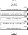
- a method for diagnosing a battery may comprise a profile obtaining step of obtaining each of a plurality of battery profiles indicating a correspondence relationship between voltage and capacity of each of a plurality of batteries; a corrected profile generating step of generating a plurality of corrected profiles by correcting the plurality of battery profiles based on a preset overpotential profile; a profile adjusting step of generating an adjusted positive electrode profile and an adjusted negative electrode profile corresponding to each battery by adjusting a preset reference positive electrode profile and a preset reference negative electrode profile to correspond to each of the plurality of corrected profiles; a diagnosis factor extracting step of extracting a diagnosis factor for each battery from at least one of the adjusted positive electrode profile and the adjusted negative electrode profile; and a state diagnosing step of diagnosing the state of the plurality of batteries based on the extracted plurality of diagnosis factors.
- a method for diagnosing a battery according to yet another aspect of the present disclosure may comprise obtaining a battery profile indicative of a voltage as a function of a capacity of a battery being charged or discharged at a target C-rate; generating a corrected profile by adjusting the battery profile according to an overpotential profile indicative of an overpotential at the target C-rate as a function of the capacity; and determining a state of the battery using the corrected profile.
- the apparatus for diagnosing a battery diagnoses the state of the battery based on a corrected profile in which the overpotential is removed from the battery profile, so charging and discharging at the reference C-rate is not forced to diagnose the state of the battery.
- the state of the battery can be diagnosed even if the battery is charged and discharged at a C-rate other than the reference C-rate, the state of the battery can be diagnosed quickly without restrictions on charging and discharging conditions.
- the apparatus for diagnosing a battery has an advantage of quickly distinguishing a normal battery and an abnormal battery by relatively comparing the states of the plurality of batteries based on the distribution of the plurality of diagnosis factors.
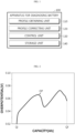
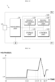
- FIG. 1 is a diagram schematically showing an apparatus 100 for diagnosing a battery according to an embodiment of the present disclosure.
- the apparatus 100 may be, for example, a battery diagnosis apparatus.
- the apparatus 100 for diagnosing a battery may include a profile obtaining unit 110, a profile correcting unit 120, and a control unit 130.
- the profile obtaining unit 110 configured to obtain a battery profile indicative of a voltage as a function of a capacity of a battery being charged or discharged at a target C-rate.
- the profile obtaining unit 110 may be configured to obtain each of a plurality of battery profiles BP indicating the correspondence relationship between the voltage and capacity of each of a plurality of batteries.
- the battery may have a negative terminal and a positive terminal.
- the battery may be a lithium-ion battery or a lithium polymer battery.
- the type of battery may be a cylindrical type, a prismatic type, or a pouch type.
- the battery may refer to an independent cell that has a negative terminal and a positive terminal.
- the battery may refer to a battery bank, a battery module or a battery pack in which a plurality of cells are connected in series and/or parallel. Below, for convenience of explanation, the battery may be considered one independent cell in the following description.
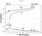
- the battery profile BP is a profile that represents the correspondence relationship between voltage (V) and capacity (Q) when the SOC of the battery is charged from 0% to 100%.
- the battery profile BP may represent the correspondence relationship between voltage (V) and capacity (Q) when the SOC of the battery is discharged from 100% to 0%.
- the battery profile BP can be generated based on the voltage and capacity while the battery is being charged or discharged at a constant C-rate.
- the C-rate must be kept constant while the battery profile BP is generated. That is, when the C-rate for charging and discharging is set, the set C-rate remains constant until charging and discharging ends.
- the profile obtaining unit 110 may directly receive the battery profile BP from the outside. That is, the profile obtaining unit 110 can obtain the battery profile BP by receiving the battery profile BP by being connected to the outside wired and/or wirelessly.
- the profile obtaining unit 110 may receive battery information about the voltage (V) and capacity (Q) of the battery. Additionally, the profile obtaining unit 110 may generate a battery profile BP based on the received battery information. That is, the profile obtaining unit 110 can obtain the battery profile BP by directly generating the battery profile BP based on battery information.
- the profile obtaining unit 110 may be connected to enable communication with the profile correcting unit 120.
- the profile obtaining unit 110 may be connected to the profile correcting unit 120 wired and/or wirelessly.
- the profile obtaining unit 110 can transmit the obtained battery profile BP to the profile correcting unit 120.
- the profile correcting unit 120 may be configured to generate a corrected profile by adjusting the battery profile according to an overpotential profile.
- the overpotential provide may be indicative of an overpotential as a function of the capacity of the battery.
- the profile correcting unit 120 may be configured to generate the corrected profile by adjusting the battery profile according to the overpotential profile that is selected from the plurality of overpotential profiles according to a target C-rate.
- the profile correcting unit 120 may be configured to generate a plurality of corrected profiles CP by correcting the plurality of battery profiles BP based on the preset overpotential profile OP.
- the overpotential profile OP is a profile that represents the correspondence relationship between capacity and overpotential.
- the overpotential profile OP is a profile indicating overpotential according to capacity.
- the overpotential profile OP may be a profile representing the voltage difference per capacity between the battery profile of the reference battery for the reference C-rate and the battery profile of the reference battery for the target C-rate set for the plurality of batteries.
- the overpotential profile may be obtained from a difference between a first battery profile and a second battery profile, wherein the first battery profile is obtained by charging or discharging a reference battery at a first C-rate and the second battery profile is obtained by charging or discharging a reference battery at a second C-rate that is different from the first C-rate.
- the reference C-rate is 0.05 C and the target C-rate is 0.3 C.
- the first battery profile can be obtained.
- the second battery profile can be obtained.
- the voltage difference between the first battery profile and the second battery profile for the same capacity can be calculated as overpotential. That is, the overpotential per capacity of the first battery profile and the second battery profile can be calculated, and the overpotential profile OP representing the correspondence relationship between capacity and overpotential can be generated.
- the measured voltage of the battery may include an overpotential. Therefore, by removing the battery profile based on the reference C-rate from the battery profile based on the target C-rate (calculating the voltage difference per capacity), the overpotential profile OP can be generated.
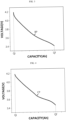
- FIG. 2 is a diagram schematically showing an overpotential profile OP according to an embodiment of the present disclosure.
- FIG. 2 is a diagram showing the overpotential profile OP generated in the process of discharging the reference battery from start capacity (Qi) to end capacity (Qf).
- the first battery profile can be generated as the reference battery is discharged from start capacity (Qi) to end capacity (Qf) at the reference C-rate.
- the second battery profile can be generated as the reference battery is discharged from start capacity (Qi) to end capacity (Qf) at the target C-rate.
- the overpotential profile OP can be generated by calculating the voltage difference per discharge capacity between the first battery profile and the second battery profile from start capacity (Qi) to end capacity (Qf).
- the profile correcting unit 120 may be configured to generate a plurality of corrected profiles CP by calculating the voltage difference per capacity between each of the plurality of battery profiles BP and the overpotential profile OP.
- the profile correcting unit 120 can remove the overpotential profile OP from the battery profile BP.
- the profile correcting unit 120 can calculate the difference between the voltage of the battery profile BP and the overpotential of the overpotential profile OP for the same capacity.
- the profile correcting unit 120 can generate a corrected profile CP by calculating the difference between the voltage of the battery profile BP and the overpotential of the overpotential profile OP at the total capacity.
- the corrected profile CP is a profile in which the overpotential profile OP is removed from the battery profile BP.
- the overpotential profile OP is a profile based on the voltage difference of the first battery profile of the reference battery for 0.05 C and the second battery profile of the reference battery for 0.3 C.
- the corrected profile CP generated by the difference between the battery profile BP and the overpotential profile OP for 0.3 C may be a profile corresponding to 0.05 C. That is, since the overpotential of the overpotential profile OP is removed from the battery profile BP for 0.3 C, the corrected profile CP for 0.05 C may be derived.
- FIG. 3 is a diagram schematically showing a battery profile BP according to an embodiment of the present disclosure.
- FIG. 4 is a diagram schematically showing a corrected profile CP according to an embodiment of the present disclosure.
- the battery profile BP in FIG. 3 is a profile obtained when the battery is discharged at the target C-rate from start capacity (Qi) to end capacity (Qf).
- the profile correcting unit 120 may generate the corrected profile CP of FIG. 4 by removing the overpotential profile OP of FIG. 2 from the battery profile BP of FIG. 3 .
- the target C-rate corresponding to the battery profile BP in FIG. 3 and the target C-rate corresponding to the overpotential profile OP in FIG. 2 are the same.
- the corrected profile CP can be generated based on the battery profile BP and the overpotential profile OP for the same target C-rate.
- the profile correcting unit 120 may be configured to generate an adjusted positive electrode profile and an adjusted negative electrode profile corresponding to each battery by adjusting a preset reference positive electrode profile and a preset reference negative electrode profile to correspond to each of the plurality of corrected profiles CP.
- the reference positive electrode profile may be a profile representing a correspondence relationship between the capacity and voltage of the preset reference positive electrode cell to correspond to the positive electrode of the battery.
- the reference positive electrode cell may be a positive electrode coin half-cell or a positive electrode of a three-electrode cell.
- the reference negative electrode profile may be a profile representing a correspondence relationship between the capacity and voltage of the preset reference negative electrode cell to correspond to the negative electrode of the battery.
- the reference negative electrode cell may be a negative electrode coin half-cell or a negative electrode of a three-electrode cell.
- the profile correcting unit 120 may adjust the reference positive electrode profile and the reference negative electrode profile to correspond to the corrected profile CP. More specifically, the profile correcting unit 120 may adjust the reference positive electrode profile and the reference negative electrode profile to generate an adjusted positive electrode profile and an adjusted negative electrode profile. Additionally, the profile correcting unit 120 may generate a comparison full-cell profile from the adjusted positive electrode profile and the adjusted negative electrode profile. The profile correcting unit 120 may adjust the reference positive electrode profile and the reference negative electrode profile until the comparison full-cell profile corresponds to the corrected profile CP.
- the profile correcting unit 120 may generate a plurality of comparison full-cell profile by shifting the reference positive electrode profile and the reference negative electrode profile or scaling the capacities thereof, and specify a comparison full-cell profile with the minimum error with the corrected profile CP among the plurality of comparison full-cell profiles. Also, an adjusted positive electrode profile and an adjusted negative electrode profile corresponding to the specified comparison full-cell profile can be determined.
- the profile correcting unit 120 determines the positive electrode profile of the battery by adjusting the reference positive electrode profile and the reference negative electrode profile to correspond to the corrected profile CP will be described later with reference to FIGS. 15 to 22 .
- profile correcting unit 120 may receive a reference electrode profile of a reference battery, and adjust the reference electrode profile to correspond to the corrected profile of the battery to thereby obtain an adjusted electrode profile using the corrected profile.
- the profile correcting unit 120 may receive a reference positive electrode profile and a reference negative electrode profile; and may adjust the reference positive electrode profile and the reference negative electrode profile in combination to correspond to the corrected profile of the battery to hereby obtain an adjusted positive electrode profile and an adjusted negative electrode profile using the corrected profile.
- the control unit 130 may be configured to determine a state of the battery using the corrected profile.
- the control unit 130 may be configured to determine the state of the battery using the adjusted electrode profile, or the control unit 130 may be configured to determine the state of the battery using the adjusted positive electrode profile and the adjusted negative electrode profile.
- the control unit 130 may be (further) configured to determine a diagnosis factor of the battery using the adjusted electrode profile, and to determine the state of the battery as a function of the diagnosis factor.
- the diagnosis factor includes at least one of an electrode start potential, an electrode end potential, an electrode change rate, and an electrode loading amount of the battery based on the adjusted electrode profile.
- the diagnosis factor includes a positive electrode factor and/or a negative electrode factor.
- control unit 130 may be configured to receive a diagnosis factor distribution and a threshold range within the diagnosis factor distribution. If the diagnosis factor is inside the threshold range, the control unit 130 may determine that the state of the battery is normal. If the diagnosis factor is outside the threshold range, the control unit 130 may determine that the state of the battery is abnormal
- control unit 130 may be configured to extract a diagnosis factor for each battery from at least one of the adjusted positive electrode profile and the adjusted negative electrode profile.
- control unit 130 can extract a diagnosis factor related to the positive electrode from the adjusted positive electrode profile. Additionally, the control unit 130 can extract a diagnosis factor related to the negative electrode from the adjusted negative electrode profile. Additionally, the control unit 130 can extract a diagnosis factor related to positive and negative electrodes by considering both the diagnosis factor related to the positive electrode and the diagnosis factor related to the negative electrode. For convenience of explanation, specific examples regarding the diagnosis factor will be described later.
- control unit 130 may extract a diagnosis factor for each of the plurality of batteries based on the adjusted positive electrode profile and/or the adjusted negative electrode profile corresponding to each of the plurality of batteries.
- diagnosis factors extracted for the plurality of batteries are the same item.
- control unit 130 can extract a plurality of diagnosis factors to correspond to the plurality of batteries.
- the control unit 130 may be configured to diagnose the state of the plurality of batteries based on the extracted plurality of diagnosis factors.
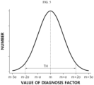
- the threshold range TH is not limited to the range of m-2 ⁇ to m+2 ⁇ .
- the apparatus 100 for diagnosing a battery diagnoses the state of the battery based on the corrected profile CP in which the overpotential is removed from the battery profile BP, so there is an advantage in that charging and discharging at the reference C-rate is not forced to diagnose the state of the battery.
- the state of the battery can be diagnosed even if the battery is charged and discharged at a C-rate other than the reference C-rate, the state of the battery can be diagnosed quickly without restrictions on charging and discharging conditions.
- the apparatus 100 for diagnosing a battery has an advantage of quickly distinguishing a normal battery and an abnormal battery by relatively comparing the states of the plurality of batteries based on the distribution of the plurality of diagnosis factors.
- control unit 130 included in the apparatus 100 for diagnosing a battery optionally include a processor, an application-specific integrated circuit (ASIC), other chipset, a logic circuit, a register, a communication modem, a data processing device, etc. known in the art to execute various control logics performed in the present disclosure.
- control logic when the control logic is implemented as software, the control unit 130 may be implemented as a set of program modules.
- the program module may be stored in the memory and executed by the control unit 130.
- the memory may be inside or outside the control unit 130 and may be connected to the control unit 130 by various well-known means.
- the apparatus 100 for diagnosing a battery may further include a storage unit 140.
- the storage unit 140 may store data necessary for operation and function of each component of the apparatus 100 for diagnosing a battery, data generated in the process of performing the operation or function, or the like.
- the storage unit 140 is not particularly limited in its kind as long as it is a known information storage means that can record, erase, update and read data.
- the information storage means may include RAM, flash memory, ROM, EEPROM, registers, and the like.
- the storage unit 140 may store program codes in which processes executable by the control unit 130 are defined.
- the storage unit 140 can store the plurality of battery profiles BP, the overpotential profile OP, the plurality of corrected profiles CP, the reference positive electrode profile, the reference negative electrode profile, the adjusted positive electrode profile, the adjusted negative electrode profile, and the plurality of diagnosis factors.
- the storage unit 140 can store a plurality of overpotential profiles each indicative of an overpotential at a respective one of different C-rates as a function of the capacity.
- the process of diagnosing the state of the battery according to the obtained battery profile BP may also take additional time. That is, according to the conventional method, since a considerable amount of time is required in the process of obtaining the battery profile BP, there is a problem in that the state of the battery cannot be quickly diagnosed.
- the battery profile BP can be obtained in about 3 hours.
- the time required to obtain the battery profile BP can be dramatically reduced compared to the conventional method.
- the apparatus 100 for diagnosing a battery may generate a corrected profile CP by removing the overpotential from the battery profile BP, and diagnose the state of the battery according to the generated corrected profile CP. Therefore, even considering the additional time required in the process of generating the corrected profile CP and diagnosing the state of the battery, there is an advantage in that the apparatus 100 for diagnosing a battery can diagnose the state of the battery very quickly compared to the conventional method.
- the overpotential profile OP can be configured to be stored in advance for each of the plurality of C-rates.
- a plurality of overpotential profiles OP may be provided, and the C-rates respectively corresponding to the plurality of overpotential profiles OP may be different.
- an overpotential profile OP corresponding to each C-rate may be stored in advance.
- the profile correcting unit 120 may be configured to select an overpotential profile OP corresponding to the target C-rate among the plurality of overpotential profiles OP stored in advance.
- the profile correcting unit 120 may be configured to generate a plurality of corrected profiles CP using the selected overpotential profile OP.
- the C-rate for the battery may change due to various environmental factors. Therefore, the C-rate for the battery may not be included in the plurality of C-rates corresponding to the pre-stored overpotential profile OP. In this case, if the overpotential included in the battery profile BP is removed based on the battery profile BP and the overpotential profile OP having different C-rates, the generated corrected profile CP may not accurately reflect the state of the battery.
- the profile correcting unit 120 may determine two C-rates adjacent to the C-rate for the battery among the plurality of C-rates, and generate an overpotential profile OP corresponding to the C-rate for the battery by interpolating the overpotential profiles corresponding to the determined C-rate. Additionally, the profile correcting unit 120 may generate a corrected profile CP by removing the overpotential included in the battery profile BP based on the battery profile BP and the generated overpotential profile OP.
- the control unit 130 can determine the charging and discharging process (charging process or discharging process) corresponding to the battery profile BP. For example, the control unit 130 can determine the charging and discharging process of the battery profile BP by comparing the sizes of start capacity and end capacity. Additionally, the control unit 130 may select the corresponding overpotential profile OP based on the determined charging and discharging process and the target C-rate.
- the apparatus 100 for diagnosing a battery can more accurately diagnose the state of a plurality of batteries by selecting an overpotential profile OP in consideration of the target C-rate and the charging and discharging process.
- the control unit 130 may be configured to extract at least one of a positive electrode factor based on the adjusted positive electrode profile, a negative electrode factor based on the adjusted negative electrode profile, and a positive and negative electrode factor based on the positive electrode factor and the negative electrode factor as a diagnosis factor.
- the adjusted positive electrode profile is the result of adjusting the reference positive electrode profile
- the adjusted negative electrode profile is the result of adjusting the reference negative electrode profile.
- the profile adjustment unit can adjust the reference positive electrode profile and the reference negative electrode profile so that the comparison full-cell profile (generated based on the reference positive electrode profile and the reference negative electrode profile) corresponds to the corrected profile CP.
- the positive electrode factor may include at least one of a positive electrode start potential, a positive electrode end potential, a positive electrode change rate, and a positive electrode loading amount of the battery based on the adjusted positive electrode profile.
- the positive electrode start potential is a start potential of the adjusted positive electrode profile
- the positive electrode end potential is an end potential of the adjusted positive electrode profile.
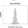
- the positive electrode start potential is a potential value of the positive electrode participation initiating point pi of the adjusted positive electrode profile.
- the positive electrode end potential is a potential value of the positive electrode participation finalizing point pf of the adjusted positive electrode profile.
- the positive electrode change rate (ps) may mean a change rate [%] of the adjusted positive electrode profile with respect to the reference positive electrode profile.
- the positive electrode change rate (ps) may be a contraction rate or expansion rate of the adjusted positive electrode profile with respect to the reference positive electrode profile. For example, if the adjusted positive electrode profile is 10% shrinkage from the reference positive electrode profile, the positive electrode change rate (ps) is 90%. Conversely, if the adjusted positive electrode profile is 10% extension of the reference positive electrode profile, the positive electrode change rate (ps) is 110%.
- control unit 130 can calculate the positive electrode loading amount (p_loading) based on the positive electrode change rate (ps), the reference positive electrode capacity, and the reference area using Equation 1 below.
- p_loading ps ⁇ Q rc ⁇ A pc
- p_loading represents the positive electrode loading amount
- ps represents the positive electrode change rate
- Q rc represents the reference positive electrode capacity
- a pc represents the reference area.
- the negative electrode factor may include at least one of a negative electrode start potential, a negative electrode end potential, a negative electrode change rate, and a negative electrode loading amount of the battery based on the adjusted negative electrode profile.
- the negative electrode start potential is a start potential of the adjusted negative electrode profile
- the negative electrode end potential is an end potential of the adjusted negative electrode profile.
- the negative electrode start potential is a potential value of the negative electrode participation initiating point ni of the adjusted negative electrode profile.
- the negative electrode end potential is a potential value of the negative electrode participation finalizing point nf of the adjusted negative electrode profile.
- the negative electrode change rate (ns) may mean the change rate [%] of the adjusted negative electrode profile with respect to the reference negative electrode profile.
- the negative electrode change rate (ns) may be the contraction rate or expansion rate of the adjusted negative electrode profile with respect to the reference negative electrode profile. For example, if the adjusted negative electrode profile is 10% shrinkage from the reference negative electrode profile, the negative electrode change rate (ns) is 90%. Conversely, if the adjusted negative electrode profile is 10% extension of the reference negative electrode profile, the negative electrode change rate (ns) is 110%.
- the negative electrode loading amount (n_loading) refers to the amount of negative electrode active material coated on the negative electrode current collector. Since the adjusted negative electrode profile is a profile indicating the current state of the negative electrode of the battery, the control unit 130 can calculate the negative electrode loading amount (n _loading) based on the adjusted negative electrode profile. Specifically, the control unit 130 may calculate the negative electrode loading amount (n _loading) in consideration of the negative electrode change rate (ns), a preset reference negative electrode capacity, and a preset reference area.
- the reference negative electrode capacity may mean the capacity of a preset reference negative electrode cell.
- the reference area may mean the area of a preset reference negative electrode cell.
- the NP ratio refers to the rate of positive electrode loading amount to negative electrode loading amount.
- np ratio is the NP ratio
- p-loading is the positive electrode loading amount according to Equation 1
- n-loading is the negative electrode loading amount according to Equation 2.
- the apparatus 100 for diagnosing a battery may extract at least one of the positive electrode start potential, the positive electrode end potential, the positive electrode change rate, the positive electrode loading amount, the negative electrode start potential, the negative electrode end potential, the negative electrode change rate, and the NP ratio as a diagnosis factor.
- the apparatus 100 for diagnosing a battery can diagnose the state of the plurality of batteries as normal state or abnormal state based on the distribution per extracted diagnosis factor.
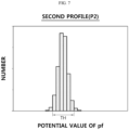
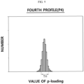
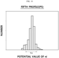
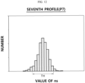
- FIGS. 6 to 14 are diagrams showing the distribution of diagnosis factors according to an embodiment of the present disclosure.
- FIG. 12 is a seventh profile P7 showing the distribution of a plurality of negative electrode change rates
- FIG. 13 is an eighth profile P8 showing the distribution of a plurality of negative electrode loading amounts
- FIG. 14 is a ninth profile P9 showing the distribution of a plurality of NP ratios. As in the previous embodiment, in FIGS. 6 to 14 , it is assumed that the 2 standard deviation range for the average value is set as the threshold range TH.
- control unit 130 can diagnose the state of the plurality of batteries according to the distribution of the extracted plurality of diagnosis factors.
- the item of interest may be selected as the positive electrode start potential.
- the control unit 130 may extract the positive electrode start potential from the plurality of adjusted positive electrode profiles for the plurality of batteries. Additionally, the control unit 130 may select a positive electrode start potential outside the threshold range TH among the plurality of positive electrode start potentials. That is, the control unit 130 may select a positive electrode start potential that exceeds the upper limit (m+2 ⁇ ) of the threshold range TH or is less than the lower limit (m-2 ⁇ ) of the threshold range TH. Additionally, the control unit 130 may diagnose the state of the battery corresponding to the selected positive electrode start potential as an abnormal state. Conversely, the control unit 130 can diagnose the state of the remaining battery as a normal state.
- control unit 130 may diagnose the state of a battery in which the counted number is more than half of the plurality of items of interest as an abnormal state. Conversely, the control unit 130 can diagnose the state of the remaining battery as a normal state. Specifically, when 5 items of interest are selected, the state of the battery with 3 or more items of interest whose diagnosis factor is outside the threshold range TH may be diagnosed as an abnormal state.
- the control unit 130 may select a battery whose negative electrode start potential is outside the threshold range TH in the fifth profile P5 and increase the counting value for the selected battery by 1.
- the control unit 130 may select a battery whose negative electrode end potential is outside the threshold range TH in the sixth profile P6 and increase the counting value for the selected battery by 1.
- the control unit 130 may select a battery whose NP ratio is outside the threshold range TH in the ninth profile P9 and increase the counting value for the selected battery by 1.
- the control unit 130 may diagnose the state of a battery with a counting value of 3 or more among the plurality of batteries as an abnormal state, and diagnose the state of the remaining batteries as a normal state.
- the profile correcting unit 120 may be configured to generate a comparison full-cell profile based on the reference positive electrode profile and the reference negative electrode profile.
- the comparison full-cell profile can be generated according to the voltage difference per capacity for the reference positive electrode profile and the reference negative electrode profile. For example, it is assumed that the voltage of the reference positive electrode profile corresponding to a certain capacity x is Vp, and the voltage of the reference negative electrode profile is Vn. The voltage of the comparison full-cell profile corresponding to the capacity X can be calculated as "Vp - Vn".
- the profile correcting unit 120 may generate a comparison full-cell profile by calculating the voltage difference between the reference positive electrode profile and the reference negative electrode profile for the entire capacity.
- the profile correcting unit 120 may be configured to generate an adjusted positive electrode profile and an adjusted negative electrode profile by adjusting the reference positive electrode profile and the reference negative electrode profile until the generated comparison full-cell profile corresponds to the corrected profile CP.
- the profile correcting unit 120 may calculate an error between the comparison full-cell profile and the corrected profile CP. Additionally, the profile correcting unit 120 may adjust the reference positive electrode profile and the reference negative electrode profile until the error between the comparison full-cell profile and the corrected profile CP is minimized. If the comparison full-cell profile that minimizes the error with the corrected profile CP is determined, the adjusted positive electrode profile and the adjusted negative electrode profile, which are the basis of the determined comparison full-cell profile, may be estimated as the positive electrode profile and the negative electrode profile that represent the current state of the battery. With current technology, there is a problem that it is not possible to directly obtain the positive electrode profile and the negative electrode profile indicating the current state of the battery without directly disassembling the battery. Therefore, it can be strongly assumed that the adjusted positive electrode profile and the adjusted negative electrode profile, which are the basis of the comparison full-cell profile determined through the adjustment process, are the positive electrode profile and the negative electrode profile that reflect the current state of the battery.
- the profile correcting unit 120 adjusts the reference positive electrode profile and the reference negative electrode profile will be described in more detail.
- FIGS. 15 to 22 are diagrams for explaining the process of adjusting a reference positive electrode profile and a reference negative electrode profile according to an embodiment of the present disclosure.
- the corrected profile CP according to an embodiment of the present disclosure is described as a measurement full-cell profile M.
- the profile correcting unit 120 may be configured to compare the measurement full-cell profile M and at least one comparison full-cell profile.
- the comparison full-cell profile may be the result of synthesizing (combining) the adjusted positive electrode profile and the adjusted negative electrode profile based on the reference positive electrode profile Rp and the reference negative electrode profile Rn, respectively, stored in the storage unit 140.
- the profile correcting unit 120 may generate a plurality of comparison full-cell profiles from the reference positive electrode profile Rp and the reference negative electrode profile Rn by repeating the process of adjusting each of the reference positive electrode profile Rp and the reference negative electrode profile Rn to various levels and then synthesizing them.
- the comparison full-cell profile can also be called an 'adjusted reference full-cell profile'.
- various methods known at the filing time of the present disclosure can be employed to determine the error between two profiles, each of which can be expressed in a two-dimensional coordinate system.
- the integral value of the absolute value of the area between two profiles or RMSE (Root Mean Square Error) can be used as the error between two profiles.
- various state information about the battery can be obtained based on the finally determined positive electrode profile and negative electrode profile.
- the finally determined positive electrode profile and negative electrode profile may be mapped to the comparison full-cell profile mapped to the minimum error.
- the comparison full-cell profile based on the finally determined positive electrode profile and negative electrode profile is almost identical to measurement full-cell profile M in terms of shape.
- the positive electrode profile and the negative electrode profile of the battery can be obtained even without disassembling the battery.
- the positive electrode profile and the negative electrode profile of the battery can be analyzed to more easily diagnose whether a defect has occurred in the battery and, if so, what type of defect it is.
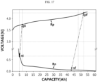
- FIGS. 17 to 19 are diagrams referenced to for explaining an example of a procedure for generating a comparison full-cell profile used for comparison with the measurement full-cell profile M according to an embodiment of the present disclosure.
- the procedure for generating a comparison full-cell profile proceeds in the following order: a first routine that sets four points (positive electrode participation initiating point, positive electrode participation finalizing point, negative electrode participation initiating point, negative electrode participation finalizing point) to correspond to the voltage range of interest (see FIG. 17 ), a second routine that performs profile shifting (see FIG. 18 ), and a third routine that performs capacity scaling (see FIG. 19 ). That is, the procedure for generating a comparison full-cell profile according to an embodiment of the present disclosure includes the first to third routines.
- the reference positive electrode profile Rp and the reference negative electrode profile Rn are the same as those shown in FIG. 15 .
- the profile correcting unit 120 determines a positive electrode participation initiating point pi, a positive electrode participation finalizing point pf, a negative electrode participation initiating point ni, and a negative electrode participation finalizing point nf on the reference positive electrode profile Rp and the reference negative electrode profile Rn.
- the profile correcting unit 120 divides the positive electrode voltage range from the starting point of the reference positive electrode profile Rp to the end point (or second setting voltage) into a plurality of micro voltage sections, and then set the boundary point of two adjacent micro voltage sections among the plurality of micro voltage sections as the positive electrode participation initiating point pi.
- Each micro voltage section may have a predetermined size (e.g., 0.01 V).
- the profile correcting unit 120 may set a point on the reference negative electrode profile Rn, which is smaller than the positive electrode participation initiating point pi by the first setting voltage (e.g., 3 V), as the negative electrode participation initiating point ni.
- Either the positive electrode participation finalizing point pf and the negative electrode participation finalizing point nf depends on the other.
- the profile correcting unit 120 may divide the voltage range from the second setting voltage to the end point of the reference positive electrode profile Rp into a plurality of micro voltage sections of a predetermined size, and then set the boundary point of two adjacent micro voltage sections among the plurality of micro voltage sections as the positive electrode participation finalizing point pf.
- the profile correcting unit 120 may set a point on the reference negative electrode profile Rn, which is smaller than the positive electrode participation finalizing point pf by a second setting voltage (e.g., 4 V), as the negative electrode participation finalizing point nf.
- a second setting voltage e.g. 4 V
- the profile correcting unit 120 may divide the negative electrode voltage range from the start point to the end point of the reference negative electrode profile Rn into a plurality of micro voltage sections of a predetermined size, and then set the boundary point of two adjacent micro voltage sections among the plurality of micro voltage sections as the negative electrode participation finalizing point nf. Next, the profile correcting unit 120 may search for a point, which is greater than the negative electrode participation finalizing point nf by a second setting voltage, from the reference positive electrode profile Rp and set the searched point as the positive electrode participation finalizing point pf.
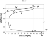
- the profile correcting unit 120 shifts at least one of the reference positive electrode profile Rp and the reference negative electrode profile Rn to the left or right along the horizontal axis.
- the profile correcting unit 120 may shift the reference positive electrode profile Rp and/or the reference negative electrode profile Rn so that the capacity values of the positive electrode participation initiating point pi and the negative electrode participation initiating point ni match.
- FIG. 18 shows the situation that the adjusted reference positive electrode profile Rp' is generated by shifting only the reference positive electrode profile Rp to the left, and as a result, the voltage of the positive electrode participation initiating point pi' matches the voltage of the negative electrode participation initiating point ni.
- the adjusted reference positive electrode profile Rp' is the result of applying an adjustment procedure of shifting to the left by the voltage difference between the positive electrode participation initiating point pi and the negative electrode participation initiating point ni to the reference positive electrode profile Rp. Therefore, the two points pi, pi' differ only in capacity value and have the same voltage.
- the two points pf, pf' differ only in capacity value and have the same voltage.
- the profile correcting unit 120 scales the capacity range of at least one of the adjustment result profiles Rp', Rn.
- the profile correcting unit 120 may generate an adjusted reference positive electrode profile Rp" by shrinking or expanding the adjusted reference positive electrode profile Rp' so that the size of the capacity range between the two points pi', pf' of the adjusted reference positive electrode profile Rp' matches the size of the capacity range of the measurement full-cell profile M.
- any one of the two points pi', pf' can be fixed. Accordingly, the capacity difference between the two points pi', pf" of the adjusted reference positive electrode profile Rp" can be matched to the capacity range of the measurement full-cell profile M.
- the profile correcting unit 120 may generate an adjusted reference negative electrode profile Rn' by shrinking or expanding the reference negative electrode profile Rn so that the size of the capacity range between two points ni, nf of the reference negative electrode profile Rn matches the size of the capacity range of the measurement full-cell profile M.
- any one of the two points ni, nf can be fixed. Accordingly, the capacity difference between the two points ni, nf' of the adjusted reference negative electrode profile Rn' can be matched to the capacity range of the measurement full-cell profile M.
- the capacity difference between the positive electrode participation initiating point pi' and the positive electrode participation finalizing point pf' of the adjusted reference positive electrode profile Rp" corresponds to the size of the capacity range of the measurement full-cell profile M.
- the capacity difference between the negative electrode participation initiating point ni and the negative electrode participation finalizing point nf' of the adjusted reference negative electrode profile Rn' corresponds to the size of the capacity range of the measurement full-cell profile M.
- the capacity range by two points pi', pf" of the adjusted reference positive electrode profile Rp" matches the capacity range by two points ni, nf' of the adjusted reference negative electrode profile Rn'.
- the profile correcting unit 120 may generate the comparison full-cell profile S by subtracting the profile between two points pi, pf' of the adjusted reference positive electrode profile Rp" from the profile between two points ni, nf of the adjusted reference negative electrode profile Rn'.
- the profile correcting unit 120 can calculate the error (profile error) between the comparison full-cell profile S and the measurement full-cell profile M.
- the adjusted reference positive electrode profile Rp" corresponding to the comparison full-cell profile S may be determined as the adjusted positive electrode profile
- the adjusted reference negative electrode profile Rn' may be determined as the adjusted negative electrode profile.
- the profile correcting unit 120 may map at least two of the adjusted reference positive electrode profile Rp", the adjusted reference negative electrode profile Rn', the positive electrode participation initiating point pi', the positive electrode participation finalizing point pf", the negative electrode participation initiating point ni, the negative electrode participation finalizing point nf', the first scale factor, the second scale factor, the comparison full-cell profile S, and the profile error to each other and record in the storage unit 140.
- the first scale factor can represent the rate of the capacity difference between two points pi', pf" relative to the capacity difference between two points pi0, pf0.
- the second scale factor may represent the rate of the capacity difference between two points ni, nf relative to the capacity difference between two points ni0, nf0.
- the profile correcting unit 120 may calculate the positive electrode change rate (ps) of the adjusted reference positive electrode profile Rp" for the reference positive electrode profile Rp. Also, the profile correcting unit 120 may calculate the negative electrode change rate (ns) of the adjusted reference positive electrode profile Rn' for the reference negative electrode profile Rn. For example, the profile correcting unit 120 may determine the first scale factor as the positive electrode change rate (ps) and determine the second scale factor as the negative electrode change rate (ns).
- the boundary point of two adjacent micro voltage sections among the plurality of micro voltage sections may be set as the positive electrode participation initiating point pi.
- the positive electrode voltage range of the reference positive electrode profile Rp is divided into one hundred small voltage ranges, there may be one hundred boundary points that can be set as the positive electrode participation initiating point pi.
- the voltage range equal to or greater than the second setting voltage in the reference positive electrode profile Rp is divided into 40 small voltage ranges, there can be 40 boundary points that can be set as the positive electrode participation finalizing point pf. In this case, up to 4000 different comparison full-cell profiles can be generated.
- the profile correcting unit 120 may identify the minimum value among the profile errors of the plurality of comparison full-cell profile generated as described above, and then obtain information mapped to the minimum profile error (e.g., at least one of the positive electrode participation initiating point pi, the positive electrode participation finalizing point pf, the negative electrode participation initiating point ni, the negative electrode participation finalizing point nf, the positive electrode change rate (ps), and the negative electrode change rate (ns)) from the storage unit 140.
- the minimum profile error e.g., at least one of the positive electrode participation initiating point pi, the positive electrode participation finalizing point pf, the negative electrode participation initiating point ni, the negative electrode participation finalizing point nf, the positive electrode change rate (ps), and the negative electrode change rate (ns)
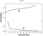
- FIGS. 20 to 22 are diagrams referenced to for explaining another example of a procedure for generating a comparison full-cell profile used for comparison with the measurement full-cell profile M according to an embodiment of the present disclosure.
- the embodiments shown in FIGS. 20 to 22 are independent from the embodiments shown in FIGS. 17 to 19 . Accordingly, terms or symbols commonly used in describing the embodiments shown in FIGS. 17 to 19 and the embodiments shown in FIGS. 20 to 22 should be understood as being limited to each embodiment.
- the generation procedure of the comparison full-cell profile to be explained with reference to FIGS. 20 to 22 proceeds in the following order: a fourth routine for performing capacity scaling (see FIG. 20 ), a fifth routine of setting four points (the positive electrode participation initiating point, the positive electrode participation finalizing point, the negative electrode participation initiating point and the negative electrode participation finalizing point (see FIG. 21 ), and a sixth routine of performing profile shift (see FIG. 22 ). That is, the generation procedure of the comparison full-cell profile according to another embodiment of the present disclosure includes the fourth to sixth routine.
- the reference positive electrode profile Rp and the reference negative electrode profile Rn are the same as those shown in FIG. 15 .
- the profile correcting unit 120 generates an adjusted reference positive electrode profile Rp' and an adjusted reference negative electrode profile Rn' by applying the first scale factor and the second scale factor selected from the scaling value range to the reference positive electrode profile Rp and the reference negative electrode profile Rn, respectively.
- the scaling value range may be predetermined or may vary depending on the rate of the size of the capacity range of the measurement full-cell profile M relative to the size of the capacity range of the reference full-cell profile R.
- the first scale factor and the second scale factor can be selected among the values spaced by 0.1% (i.e., 90%, 90.1%, 90.2%, ..., 98.9%, 99%) in the scaling numerical range (e.g., 90 to 99%)
- 91 values can be selected as the first scale factor and the second scale factor, respectively.
- the adjusted profile pair refers to a combination of the adjusted reference positive electrode profile and the adjusted reference negative electrode profile.
- FIG. 20 shows an example in which the adjusted reference positive electrode profile Rp' and the adjusted reference negative electrode profile Rn' are the results of applying a first scale factor and a second scale factor less than 100% to the reference positive electrode profile Rp and the reference negative electrode profile Rn, respectively.
- the adjusted reference positive electrode profile Rp' is the shrinkage of the reference positive electrode profile Rp along the horizontal axis
- the adjusted reference negative electrode profile Rn' is also the shrinkage of the reference negative electrode profile Rn along the horizontal axis.
- the example is illustrated in the form where the starting point of each of the positive electrode profile Rp and the reference negative electrode profile Rn is fixed and the remaining portions are reduced to the left along the horizontal axis.
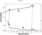
- the profile correcting unit 120 determines the positive electrode participation initiating point pi', the positive electrode participation finalizing point pf', the negative electrode participation initiating point ni' and the negative electrode participation finalizing point nf' on the adjusted reference positive electrode profile Rp' and the adjusted reference negative electrode profile Rn'.
- Either the positive electrode participation initiating point pi' or the negative electrode participation initiating point ni' may depend on the other. Additionally, either the positive electrode participation finalizing point pf' or the negative electrode participation finalizing point nf' may depend on the other. Additionally, either the positive electrode participation initiating point pi' or the positive electrode participation finalizing point pf' may be set based on the other.
- the remaining three points may be set automatically by the first setting voltage, the second setting voltage and/or the size of the capacity range of the measurement full-cell profile M (e.g., charging capacity of SOC 0% to 100%).
- the profile correcting unit 120 may divide the positive electrode voltage range from the start point of the adjusted reference positive electrode profile Rp' to the end point (or second setting voltage) into a plurality of micro voltage section, and then set the boundary point of two adjacent micro voltage sections among the plurality of micro voltage sections as the positive electrode participation initiating point pi'. Next, the profile correcting unit 120 may set the point on the adjusted reference negative electrode profile Rn, which is smaller than the positive electrode participation initiating point pi' by the first setting voltage (e.g., 3 V), as the negative electrode participation initiating point ni'.
- the first setting voltage e.g. 3 V
- the profile correcting unit 120 may divide the negative electrode voltage range from the start point to the end point of the adjusted reference negative electrode profile Rn' into a plurality of micro voltage sections of a predetermined size, and then set the boundary point of two adjacent voltage sections among the plurality of micro voltage sections as the negative electrode participation initiating point ni'. Next, the profile correcting unit 120 may search for a point, which is greater than the negative electrode participation initiating point ni' by the first setting voltage, from the reference positive electrode profile Rp and set the searched point as the positive electrode participation initiating point pi'.
- the profile correcting unit 120 may divide the negative electrode voltage range from the start point to the end point of the adjusted reference negative electrode profile Rn' into a plurality of micro voltage sections of a predetermined size, and then set the boundary point of two adjacent micro voltage sections among the plurality of micro voltage sections as the negative electrode participation finalizing point nf'. Next, the profile correcting unit 120 may search for a point, which is greater than the negative electrode participation finalizing point nf b by the second setting voltage, from the adjusted reference positive electrode profile Rp' and set the searched point as the positive electrode participation finalizing point pf'.
- the profile correcting unit 120 may additionally determine the remaining points based on the determined point.
- the profile correcting unit 120 may set the point on the adjusted reference positive electrode profile Rp', which has a capacity value that is larger than the capacity value of the positive electrode participation initiating point pi' by the size of the capacity range of the measurement full-cell profile M, as the positive electrode participation finalizing point pf'. Additionally, the profile correcting unit 120 may search for a point, which is lower than the positive electrode participation initiating point pi' by the first setting voltage, from the adjusted reference negative electrode profile Rn' and set the searched point as the negative electrode participation initiating point ni'.
- the profile correcting unit 120 may set a point on the adjusted reference negative electrode profile Rn', which has a capacity value larger than the capacity value of the negative electrode participation initiating point ni' by the size of the capacity range of the measurement full-cell profile M, as the negative electrode participation finalizing point nf'.
- the profile correcting unit 120 may set a point on the adjusted reference negative electrode profile Rn', which has a capacity value smaller than the capacity value of the negative electrode participation finalizing point nf b by the size of the capacity range of the measurement full-cell profile M, as the negative electrode participation initiating point ni'.
- the profile correcting unit 120 may set a point on the reference negative electrode profile Rn', which has a capacity value larger than the capacity value of the negative electrode participation initiating point ni' by the size of the capacity range of the measurement full-cell profile M, set as the negative electrode participation finalizing point nf'. Additionally, the profile correcting unit 120 may search for a point, which is higher than the negative electrode participation initiating point ni' by the first setting voltage, from the adjusted reference positive electrode profile Rp' and set the searched point as the positive electrode participation initiating point pi'.
- the profile correcting unit 120 may set a point on the adjusted reference positive electrode profile Rp', which has a capacity value greater than the capacity value of the positive electrode participation initiating point pi' by the size of the capacity range of the measurement full-cell profile M, as the positive electrode participation finalizing point pf'.
- the profile correcting unit 120 may shift at least one of the adjusted reference positive electrode profile Rp' and the adjusted reference negative electrode profile Rn' along the horizontal axis so that the capacity values of the positive electrode participation initiating point pi' and the negative electrode participation initiating point ni' match or the capacity values of the positive electrode participation finalizing point pf' and the negative electrode participation finalizing point nf' match.
- the adjusted reference negative electrode profile Rn" shown in FIG. 22 is obtained by shifting only the adjusted reference negative electrode profile Rn' shown in FIG. 21 to the right. Accordingly, the capacity values of the positive electrode participation initiating point pi' and the negative electrode participation initiating point ni" do not match each other.
- the capacity difference between the positive electrode participation initiating point pi' and the positive electrode participation finalizing point pf' is the same as the capacity difference between the negative electrode participation initiating point ni' and the negative electrode participation finalizing point nf', if the capacity values of the positive electrode participation initiating point pi' and the negative electrode participation initiating point ni" match each other, the capacity values of the positive electrode participation finalizing point pf' and the negative electrode participation finalizing point nf" also match each other.
- the profile correcting unit 120 may generate the comparison full-cell profile U by subtracting a partial profile between two points pi', pf' of the adjusted reference positive electrode profile Rp' from the partial profile between into two points ni", nf" of the adjusted reference negative electrode profile Rn".
- the profile correcting unit 120 may calculate the error (profile error) between the comparison full-cell profile U and the measurement full-cell profile M.
- the adjusted reference positive electrode profile Rp' corresponding to the comparison full-cell profile U may be determined as the adjusted positive electrode profile
- the adjusted reference negative electrode profile Rn" may be determined as the adjusted negative electrode profile.
- the profile correcting unit 120 may map at least two of the adjusted reference positive electrode profile Rp', the adjusted reference negative electrode profile Rn", the positive electrode participation initiating point pi', the positive electrode participation finalizing point pf', the negative electrode participation initiating point ni", the negative electrode participation finalizing point nf', the positive electrode change rate ps, the negative electrode change rate ns, the comparison full-cell profile U, and the profile error with each other and record in the storage unit 140.
- the profile correcting unit 120 may calculate the positive electrode change rate ps of the adjusted reference positive electrode profile Rp' for the reference positive electrode profile Rp. Also, the profile correcting unit 120 may calculate the negative electrode change rate ns of the adjusted reference negative electrode profile Rn" for the reference negative electrode profile Rn. For example, the profile correcting unit 120 may determine the first scale factor as the positive electrode change rate ps and determine the second scale factor as the negative electrode change rate ns.
- the profile correcting unit 120 may generate a comparison full-cell profile corresponding to each pair of first scale factor and second scale factor selected from the scaling value range. Since the pair of first scale factor and second scale factor is plural, it is obvious that the comparison full-cell profile will also be generated in plural.
- the profile correcting unit 120 may identify the minimum value among the profile errors of the plurality of comparison full-cell profiles and then obtain information mapped to the minimum profile error from the storage unit 140.
- the apparatus 100 for diagnosing a battery according to the present disclosure may be connected to a display device (not shown) and output information on a battery diagnosed as being in an abnormal state. Because of this, the information about the battery diagnosed as being in an abnormal state may be displayed on the display device.
- the apparatus 100 for diagnosing a battery according to the present disclosure may be connected to an alarm device (not shown) and output information on a battery diagnosed as being in an abnormal state to operate the alarm device.
- the apparatus 100 for diagnosing a battery according to the present disclosure can be applied to the BMS.
- the BMS according to the present disclosure may include the above-described apparatus 100 for diagnosing a battery.
- at least some of the components of the apparatus 100 for diagnosing a battery may be implemented by supplementing or adding functions of components included in a conventional BMS.
- the profile obtaining unit 110, the profile correcting unit 120, the control unit 130 and the storage unit 140 of the apparatus 100 for diagnosing a battery may be implemented as components of a BMS.
- the apparatus 100 for diagnosing a battery according to the present disclosure may be provided in the battery pack. That is, the battery pack according to the present disclosure may include the above-described apparatus 100 for diagnosing a battery and at least one battery cell. Additionally, the battery pack may further include electrical components (relays, fuses, etc.) and a case.
- FIG. 23 is a diagram showing an exemplary configuration of the battery pack 1 including according to another embodiment of the present disclosure.
- the positive electrode terminal of the battery 10 may be connected to the positive electrode terminal P+ of the battery pack 1, and the negative electrode terminal of the battery 10 may be connected to the negative electrode terminal P- of the battery pack 1.
- the measuring unit 20 can be connected to the positive electrode terminal and the negative electrode terminal of the battery 10. Additionally, the measuring unit 20 can measure the voltage of the battery 10 by measuring the positive electrode potential and the negative electrode potential of the battery 10 and calculating the difference between the positive electrode potential and the negative electrode potential.
- the measuring unit 20 can be connected to a current measurement unit A.
- the current measurement unit A may be an ammeter or shunt resistor that can measure the charging current and discharging current of the battery 10.
- the measuring unit 20 can calculate the charging amount by measuring the charging current of the battery 10 using the current measurement unit A.
- the measuring unit 20 can calculate the discharge amount by measuring the discharge current of the battery 10 through the third sensing line SL3.
- the information about the voltage and capacity of the battery 10 measured by the measuring unit 20 may be transmitted to the profile obtaining unit 110. Additionally, the profile obtaining unit 110 can directly generate a battery profile BP based on the received information about the voltage and capacity.
- the information about the voltage and capacity of the battery 10 measured by the measuring unit 20 may be stored in the storage unit 140.
- the profile obtaining unit 110 may access the storage unit 140 to obtain the battery profile BP.
- the measuring unit 20 may directly generate a battery profile BP based on the measured information about the voltage and capacity of the battery 10.
- the generated battery profile BP may be transmitted to the profile obtaining unit 110 and also be stored in the storage unit 140.
- a charge/discharge device or load can be connected to the positive electrode terminal P+ and the negative electrode terminal P- of the battery pack 1.
- FIG. 24 is a diagram for explaining the process of manufacturing a battery cell by a battery manufacturing system according to still another embodiment of the present disclosure. Specifically, FIG. 24 is a diagram schematically showing the process of activating a manufactured battery cell over time.
- the aging process proceeds in the first step from the t0 time point to the t1 time point.
- the aging process refers to a process of leaving the battery cell under specific conditions.
- the electrolyte may be impregnated.
- Primary charging proceeds in the second step from the t1 time point to the t2 time point.
- a film layer SEI, solid electrolyte interphase
- SEI solid electrolyte interphase
- a high temperature aging process proceeds in the third step from the t2 time point to the t3 time point.
- aging occurs under high temperature conditions of 60°C, and the film layer formed in the second step can be stabilized.
- the degassing process proceeds in the fourth step from the t3 time point to the t4 time point.
- the gas contained inside the battery cell can be removed.
- the process of charging the battery cell proceeds in the fifth step from the t4 time point to the t5 time point.
- the battery cell discharge process proceeds in the sixth step from the t5 time point to the t6 time point.
- the fifth step and the sixth step can be combined and referred to as the battery cell capacity inspection process.
- the sixth step is a step of detecting a defect in the battery cell while discharging a fully charged battery cell, and is a process step of discharging the battery cell at a discharge C-rate determined in consideration of the inspection time and inspection accuracy.
- the battery cell is discharged at 0.3 C, and the battery profile BP for capacity and voltage can be obtained during the discharge process. Also, based on the obtained battery profile BP, it may be detected whether the battery cell is defective.
- the shipping and charging process to ship the battery cell is carried out.
- FIG. 26 is a diagram schematically showing a method for diagnosing a battery according to still another embodiment of the present disclosure.
- the corrected profile generating step (S200) is a step for generating a plurality of corrected profiles CP by correcting the plurality of battery profiles BP based on a preset overpotential profile OP, and may be performed by the profile correcting unit 120.
- the profile correcting unit 120 may remove the overpotential profile OP from the battery profile BP.
- the profile correcting unit 120 may calculate the difference between the voltage of the battery profile BP and the overpotential of the overpotential profile OP for the same capacity.
- the profile correcting unit 120 may generate a corrected profile CP by calculating the difference between the voltage of the battery profile BP and the overpotential of the overpotential profile OP at the total capacity.
- the profile adjusting step (S300) is a step of generating an adjusted positive electrode profile and an adjusted negative electrode profile corresponding to each battery by adjusting a preset reference positive electrode profile and a preset reference negative electrode profile to correspond to each of the plurality of corrected profiles CP, and may be performed by the profile correcting unit 120.
- the profile correcting unit 120 may generate a plurality of comparison full-cell profiles by shifting the reference positive electrode profile and the reference negative electrode profile or scaling the capacity thereof, and specify a comparison full-cell profile having a minimum error with the corrected profile CP among the plurality of comparison full-cell profiles. Also, an adjusted positive electrode profile and an adjusted negative electrode profile corresponding to the specified comparison full-cell profile may be determined.
- the diagnosis factor extracting step (S400) is a step of extracting a diagnosis factor for each battery from at least one of the adjusted positive electrode profile and the adjusted negative electrode profile, and may be performed by the control unit 130.
- control unit 130 may extract a diagnosis factor related to the positive electrode from the adjusted positive electrode profile. Additionally, the control unit 130 may extract a diagnosis factor related to the negative electrode from the adjusted negative electrode profile. Additionally, the control unit 130 may extract a diagnosis factor related to the positive and negative electrodes in consideration of both the diagnosis factor related to the positive electrode and the diagnosis factor related to the negative electrode.
- the positive electrode factor may include at least one of a positive electrode start potential, a positive electrode end potential, a positive electrode change rate, and a positive electrode loading amount of the battery based on the adjusted positive electrode profile.
- the negative electrode factor may include at least one of a negative electrode start potential, a negative electrode end potential, a negative electrode change rate, and a negative electrode loading amount of the battery based on the adjusted negative electrode profile.
- the positive and negative electrode factor may include an NP ratio based on a positive electrode loading amount and a negative electrode loading amount.
- the state diagnosing step (S500) is a step of diagnosing the state of the plurality of batteries based on the extracted plurality of diagnosis factors, and may be performed by the control unit 130.
- control unit 130 may be configured to select a diagnosis factor that is outside the threshold range TH among the plurality of diagnosis factors in consideration of the distribution of the plurality of diagnosis factors, and diagnose the state of the battery corresponding to the selected diagnosis factor as an abnormal state. Conversely, the control unit 130 may be configured to select a diagnosis factor included in the threshold range TH among the plurality of diagnosis factors and diagnose the state of the battery corresponding to the selected diagnosis factor as a normal state.
- the embodiments of the present disclosure described above may not be implemented only through an apparatus and a method, but may be implemented through a program that realizes a function corresponding to the configuration of the embodiments of the present disclosure or a recording medium on which the program is recorded.
- the program or recording medium may be easily implemented by those skilled in the art from the above description of the embodiments.
Landscapes
- Physics & Mathematics (AREA)
- General Physics & Mathematics (AREA)
- Engineering & Computer Science (AREA)
- Power Engineering (AREA)
- Life Sciences & Earth Sciences (AREA)
- Sustainable Development (AREA)
- Sustainable Energy (AREA)
- Transportation (AREA)
- Mechanical Engineering (AREA)
- Secondary Cells (AREA)
- Charge And Discharge Circuits For Batteries Or The Like (AREA)
Applications Claiming Priority (1)
| Application Number | Priority Date | Filing Date | Title |
|---|---|---|---|
| KR20230115856 | 2023-08-31 |
Publications (1)
| Publication Number | Publication Date |
|---|---|
| EP4517352A1 true EP4517352A1 (de) | 2025-03-05 |
Family
ID=92582791
Family Applications (1)
| Application Number | Title | Priority Date | Filing Date |
|---|---|---|---|
| EP24196723.1A Pending EP4517352A1 (de) | 2023-08-31 | 2024-08-27 | Vorrichtung und verfahren zur batteriediagnose |
Country Status (6)
| Country | Link |
|---|---|
| US (1) | US20250076388A1 (de) |
| EP (1) | EP4517352A1 (de) |
| KR (1) | KR102825294B1 (de) |
| CN (1) | CN121100285A (de) |
| MX (1) | MX2025012148A (de) |
| WO (1) | WO2025048458A1 (de) |
Citations (3)
| Publication number | Priority date | Publication date | Assignee | Title |
|---|---|---|---|---|
| US20180145528A1 (en) * | 2016-11-22 | 2018-05-24 | Samsung Electronics Co., Ltd. | Method and apparatus for controlling battery |
| WO2022029451A1 (en) * | 2020-08-07 | 2022-02-10 | Breathe Battery Technologies Limited | Intelligent battery management system and method |
| CN114624604A (zh) * | 2022-04-02 | 2022-06-14 | 中国长江三峡集团有限公司 | 一种电池寿命预测模型生成、预测方法、装置和电子设备 |
Family Cites Families (7)
| Publication number | Priority date | Publication date | Assignee | Title |
|---|---|---|---|---|
| KR102254353B1 (ko) * | 2017-03-10 | 2021-05-21 | 주식회사 엘지화학 | 이차전지의 충전방법 |
| WO2022020255A1 (en) * | 2020-07-20 | 2022-01-27 | Milwaukee Electric Tool Corporation | Systems, methods, and devices for increased charging speed of lithium-based battery packs |
| KR102596153B1 (ko) * | 2020-08-14 | 2023-10-30 | 주식회사 엘지에너지솔루션 | 배터리 관리 장치 및 방법 |
| CN115443416B (zh) * | 2020-10-27 | 2025-09-23 | 株式会社Lg新能源 | 电池管理设备、电池组和电池管理方法 |
| KR102847768B1 (ko) * | 2020-11-17 | 2025-08-18 | 주식회사 엘지에너지솔루션 | 배터리 관리 장치 및 방법 |
| KR102834460B1 (ko) * | 2020-12-28 | 2025-07-14 | 주식회사 엘지에너지솔루션 | 이차 전지 진단 장치 및 방법 |
| KR102885238B1 (ko) * | 2021-09-08 | 2025-11-12 | 삼성전자주식회사 | 배터리 상태를 추정하는 전자 장치 및 그 동작 방법 |
-
2024
- 2024-08-27 US US18/817,149 patent/US20250076388A1/en active Pending
- 2024-08-27 KR KR1020240115048A patent/KR102825294B1/ko active Active
- 2024-08-27 WO PCT/KR2024/012785 patent/WO2025048458A1/ko active Pending
- 2024-08-27 CN CN202480031377.5A patent/CN121100285A/zh active Pending
- 2024-08-27 EP EP24196723.1A patent/EP4517352A1/de active Pending
-
2025
- 2025-10-10 MX MX2025012148A patent/MX2025012148A/es unknown
Patent Citations (3)
| Publication number | Priority date | Publication date | Assignee | Title |
|---|---|---|---|---|
| US20180145528A1 (en) * | 2016-11-22 | 2018-05-24 | Samsung Electronics Co., Ltd. | Method and apparatus for controlling battery |
| WO2022029451A1 (en) * | 2020-08-07 | 2022-02-10 | Breathe Battery Technologies Limited | Intelligent battery management system and method |
| CN114624604A (zh) * | 2022-04-02 | 2022-06-14 | 中国长江三峡集团有限公司 | 一种电池寿命预测模型生成、预测方法、装置和电子设备 |
Also Published As
| Publication number | Publication date |
|---|---|
| WO2025048458A1 (ko) | 2025-03-06 |
| KR20250033021A (ko) | 2025-03-07 |
| MX2025012148A (es) | 2025-11-03 |
| US20250076388A1 (en) | 2025-03-06 |
| CN121100285A (zh) | 2025-12-09 |
| KR102825294B1 (ko) | 2025-06-25 |
Similar Documents
| Publication | Publication Date | Title |
|---|---|---|
| US20240210478A1 (en) | Apparatus and method for managing battery | |
| US20250251455A1 (en) | Apparatus and method for generating battery information | |
| EP4517352A1 (de) | Vorrichtung und verfahren zur batteriediagnose | |
| KR102896754B1 (ko) | 배터리 진단 장치 및 방법 | |
| KR102836737B1 (ko) | 배터리 진단 장치 및 방법 | |
| KR102841039B1 (ko) | 배터리 진단 장치 및 방법 | |
| EP4682563A1 (de) | Vorrichtung und verfahren zur soh-schätzung | |
| EP4685507A1 (de) | Vorrichtung und verfahren zur soh-schätzung | |
| EP4675293A1 (de) | Vorrichtung und verfahren zur soh-schätzung | |
| EP4517351A1 (de) | Vorrichtung und verfahren zur schätzung von soh | |
| KR102825187B1 (ko) | 배터리 진단 장치 및 방법 | |
| KR102839921B1 (ko) | 배터리 진단 장치 및 방법 | |
| KR102833835B1 (ko) | 배터리 진단 장치 및 방법 | |
| KR102825271B1 (ko) | 배터리 진단 장치 및 방법 | |
| KR102839916B1 (ko) | 배터리 진단 장치 및 방법 | |
| CN121311778A (zh) | 用于诊断电池的装置和方法 | |
| CN120731379A (zh) | 用于估计soh的装置和方法 |
Legal Events
| Date | Code | Title | Description |
|---|---|---|---|
| PUAI | Public reference made under article 153(3) epc to a published international application that has entered the european phase |
Free format text: ORIGINAL CODE: 0009012 |
|
| STAA | Information on the status of an ep patent application or granted ep patent |
Free format text: STATUS: REQUEST FOR EXAMINATION WAS MADE |
|
| 17P | Request for examination filed |
Effective date: 20240827 |
|
| AK | Designated contracting states |
Kind code of ref document: A1 Designated state(s): AL AT BE BG CH CY CZ DE DK EE ES FI FR GB GR HR HU IE IS IT LI LT LU LV MC ME MK MT NL NO PL PT RO RS SE SI SK SM TR |
|
| STAA | Information on the status of an ep patent application or granted ep patent |
Free format text: STATUS: EXAMINATION IS IN PROGRESS |
|
| 17Q | First examination report despatched |
Effective date: 20251006 |