EP4517288A1 - Pressure sensor manifolds for high temperatures - Google Patents
Pressure sensor manifolds for high temperatures Download PDFInfo
- Publication number
- EP4517288A1 EP4517288A1 EP24196817.1A EP24196817A EP4517288A1 EP 4517288 A1 EP4517288 A1 EP 4517288A1 EP 24196817 A EP24196817 A EP 24196817A EP 4517288 A1 EP4517288 A1 EP 4517288A1
- Authority
- EP
- European Patent Office
- Prior art keywords
- tube
- case
- flange
- fluid communication
- pressure
- Prior art date
- Legal status (The legal status is an assumption and is not a legal conclusion. Google has not performed a legal analysis and makes no representation as to the accuracy of the status listed.)
- Granted
Links
Images


Classifications
-
- G—PHYSICS
- G01—MEASURING; TESTING
- G01M—TESTING STATIC OR DYNAMIC BALANCE OF MACHINES OR STRUCTURES; TESTING OF STRUCTURES OR APPARATUS, NOT OTHERWISE PROVIDED FOR
- G01M15/00—Testing of engines
- G01M15/14—Testing gas-turbine engines or jet-propulsion engines
-
- G—PHYSICS
- G01—MEASURING; TESTING
- G01L—MEASURING FORCE, STRESS, TORQUE, WORK, MECHANICAL POWER, MECHANICAL EFFICIENCY, OR FLUID PRESSURE
- G01L19/00—Details of, or accessories for, apparatus for measuring steady or quasi-steady pressure of a fluent medium insofar as such details or accessories are not special to particular types of pressure gauges
- G01L19/0007—Fluidic connecting means
-
- F—MECHANICAL ENGINEERING; LIGHTING; HEATING; WEAPONS; BLASTING
- F01—MACHINES OR ENGINES IN GENERAL; ENGINE PLANTS IN GENERAL; STEAM ENGINES
- F01D—NON-POSITIVE DISPLACEMENT MACHINES OR ENGINES, e.g. STEAM TURBINES
- F01D17/00—Regulating or controlling by varying flow
- F01D17/02—Arrangement of sensing elements
- F01D17/08—Arrangement of sensing elements responsive to condition of working-fluid, e.g. pressure
-
- F—MECHANICAL ENGINEERING; LIGHTING; HEATING; WEAPONS; BLASTING
- F01—MACHINES OR ENGINES IN GENERAL; ENGINE PLANTS IN GENERAL; STEAM ENGINES
- F01D—NON-POSITIVE DISPLACEMENT MACHINES OR ENGINES, e.g. STEAM TURBINES
- F01D21/00—Shutting-down of machines or engines, e.g. in emergency; Regulating, controlling, or safety means not otherwise provided for
- F01D21/003—Arrangements for testing or measuring
-
- G—PHYSICS
- G01—MEASURING; TESTING
- G01L—MEASURING FORCE, STRESS, TORQUE, WORK, MECHANICAL POWER, MECHANICAL EFFICIENCY, OR FLUID PRESSURE
- G01L19/00—Details of, or accessories for, apparatus for measuring steady or quasi-steady pressure of a fluent medium insofar as such details or accessories are not special to particular types of pressure gauges
- G01L19/0061—Electrical connection means
- G01L19/0084—Electrical connection means to the outside of the housing
-
- G—PHYSICS
- G01—MEASURING; TESTING
- G01L—MEASURING FORCE, STRESS, TORQUE, WORK, MECHANICAL POWER, MECHANICAL EFFICIENCY, OR FLUID PRESSURE
- G01L19/00—Details of, or accessories for, apparatus for measuring steady or quasi-steady pressure of a fluent medium insofar as such details or accessories are not special to particular types of pressure gauges
- G01L19/06—Means for preventing overload or deleterious influence of the measured medium on the measuring device or vice versa
- G01L19/0681—Protection against excessive heat
-
- F—MECHANICAL ENGINEERING; LIGHTING; HEATING; WEAPONS; BLASTING
- F05—INDEXING SCHEMES RELATING TO ENGINES OR PUMPS IN VARIOUS SUBCLASSES OF CLASSES F01-F04
- F05D—INDEXING SCHEME FOR ASPECTS RELATING TO NON-POSITIVE-DISPLACEMENT MACHINES OR ENGINES, GAS-TURBINES OR JET-PROPULSION PLANTS
- F05D2220/00—Application
- F05D2220/30—Application in turbines
- F05D2220/32—Application in turbines in gas turbines
-
- F—MECHANICAL ENGINEERING; LIGHTING; HEATING; WEAPONS; BLASTING
- F05—INDEXING SCHEMES RELATING TO ENGINES OR PUMPS IN VARIOUS SUBCLASSES OF CLASSES F01-F04
- F05D—INDEXING SCHEME FOR ASPECTS RELATING TO NON-POSITIVE-DISPLACEMENT MACHINES OR ENGINES, GAS-TURBINES OR JET-PROPULSION PLANTS
- F05D2240/00—Components
- F05D2240/10—Stators
-
- F—MECHANICAL ENGINEERING; LIGHTING; HEATING; WEAPONS; BLASTING
- F05—INDEXING SCHEMES RELATING TO ENGINES OR PUMPS IN VARIOUS SUBCLASSES OF CLASSES F01-F04
- F05D—INDEXING SCHEME FOR ASPECTS RELATING TO NON-POSITIVE-DISPLACEMENT MACHINES OR ENGINES, GAS-TURBINES OR JET-PROPULSION PLANTS
- F05D2260/00—Function
- F05D2260/80—Diagnostics
Definitions
- the present disclosure relates to sensor systems, and more particularly to pressure sensors such as used in gas turbine engine control.
- Normally pressure sensors that monitor compressor discharge/burner pressures (P3) in gas turbine engines are located remotely with a deadheaded line such that the temperatures are low enough to allow the sensor to be highly accurate and reasonably robust.
- a removable plumbing line using an AN (Army/Navy standard) style fitting interface at the sensor is used. This interface can result in leakage which has been shown to cause failure of the sensor to due to high temp exposure from convective heating.
- a pressure sensing system includes a housing that houses one or more pressure transducers therein.
- a tube is sealed to the housing at a first end of the tube.
- One or more pressure transducers are in fluid communication with a second end of the tube through an inner passage of the tube for sensing pressure at the second end of the tube.
- the housing can include a manifold flange with one or more pressure transducers in fluid communication with respective ports in the manifold flange.
- the tube can be integral with the manifold flange.
- the tube can be welded to the manifold flange at a weld joint that fully seals the respective ports and the inner passage of the tube in fluid communication with one another.
- the tube and the manifold flange can be metallurgically monolithic.
- the tube and the manifold flange can be additively manufactured as one piece.
- the tube and the manifold flange can be machined as a single piece.
- the respective ports in the manifold flange can each be in fluid communication with the inner passage of the tube.
- a case flange configured to be mounted to a compressor case can be in fluid communication with an interior flow path of the compressor case.
- the case flange can be connected in fluid communication with the second end of the tube for fluid communication of pressure from the interior flow path of the compressor case, through the case flange, through the inner passage of the tube, and through the ports in the manifold flange, for pressure sensing pressure in the compressor case by the one or more pressure transducers.
- the housing can include an enclosure case mounted to the manifold flange to enclose the one or more pressure transducers.
- the tube can define a labyrinthine path through a heat exchanger.
- the heat exchanger can include fins radiating outward therefrom for heat exchange with nacelle air external from the tube and heat exchanger.
- the housing can include a harness for electrical communication of signals from the one or more pressure transducers to engine control components through the housing.
- a gas turbine engine system includes an engine case.
- a housing houses one or more pressure transducers therein.
- the housing includes a manifold flange with the one or more pressure transducers in fluid communication with respective ports in the manifold flange.
- a tube is sealed to the manifold flange at a first end of the tube.
- the respective ports in the manifold flange are each in fluid communication with an inner passage of the tube.
- the one or more pressure transducers are in fluid communication with a second end of the tube through the inner passage of the tube for sensing pressure at the second end of the tube.
- a case flange is mounted to the engine case in fluid communication with an interior flow path of the engine case.
- the case flange is connected in fluid communication with the second end of the tube for fluid communication of pressure from the interior flow path of the engine case, through the case flange, through the inner passage of the tube, and through the ports in the manifold flange, for pressure sensing pressure in the engine case by the one or more pressure transducers.
- the housing can include an enclosure case mounted to the manifold flange to enclose the one or more pressure transducers.
- the tube can define a labyrinthine path through a heat exchanger.
- the heat exchanger can include fins radiating outward therefrom for heat exchange with nacelle air in a nacelle outboard of the engine case.
- the engine case can be a compressor case of a compressor section upstream of a combustor that is upstream of a turbine section.
- the housing can include a harness for electrical communication of signals from the one or more pressure transducers to engine control components through the housing.
- the case flange can be connected in fluid communication with the engine case through an fitting joint.
- FIG. 1 a partial view of an embodiment of a system in accordance with the disclosure is shown in Fig. 1 and is designated generally by reference character 100.
- FIGs. 2-4 Other embodiments of systems in accordance with the disclosure, or aspects thereof, are provided in Figs. 2-4 , as will be described.
- the systems and methods described herein can be used to provide pressure sensors that avoid high temperature flow reaching sensitive component, counteracting potential installation errors or variations.
- a gas turbine engine system 10 includes a compressor section 12 that supplies pressurized air to a combustor 14 downstream thereof.
- the combustor adds heat and combustion products to the pressurized air to drive a downstream turbine section 16.
- the turbine section 16 mechanically drives the compressor section 12.
- a nacelle 18 houses the compressor section 12, the combustor 14, and the turbine section 16.
- a first gas path is defined through the compressor section 12, the combustor 14, and the turbine section 16.
- a second, separate gas path 20 is defined through the nacelle 18 outboard of the compressor section 12, combustor 14, and turbine section 16.
- the engine system 10 includes a pressure sensing system 100.
- the pressure sensing system 100 includes a housing 102 that houses one or more pressure transducers 104 therein.
- the housing 102 includes a manifold flange 106 with the one or more pressure transducers 104 in fluid communication with respective ports 108 in the manifold flange 106.
- a tube 110 is integral with the manifold flange 106 at a first end 111 of the tube 110.
- the respective ports 108 in the manifold flange 106 are each in fluid communication with an inner passage 112 of the tube 110.
- the one or more pressure transducers 104 are in fluid communication with a second end 113 of the tube 110 through the inner passage 112 for sensing pressure at the second end 113 of the tube 110.
- the housing 102 includes an enclosure case 114 mounted, e.g., welded, to the manifold flange 106 to enclose the one or more pressure transducers 104.
- a case flange 116 is mounted, e.g. bolted, to the engine case 13, i.e. the compressor case of the compressor section 12 in Fig. 1 .
- the case flange 116 includes an inner passage 118 therethrough in fluid communication with an interior flow path 120 of the engine case 13.
- the case flange 116 is connected with its inner passage 118 in fluid communication with inner passage 112 at the second end 113 of the tube 110. This provides fluid communication of pressure from the interior flow path 120 of the engine case 13, through the case flange 116, through the inner passage 112 of the tube 110, and through the ports 108 in the manifold flange 106, for pressure sensing pressure in the engine case 13 by the one or more pressure transducers 104.
- the tube is sealed, e.g. with a polymeric seal, or by being integral as described below, with the manifold flange 106, so there is no AN (Army/Navy standard) flair fitting joint connecting the tube 110 to the housing 102.
- the tube 110 can be welded to the manifold flange 106 at a weld joint that fully seals the respective ports 108 and the inner passage 112 of the tube 110 in fluid communication with one another.
- the tube 110 and the manifold flange 106 can be metallurgically monolithic, i.e. with no weld or heat effected zone connecting the two, e.g.
- the housing 102 includes a harness 122 electrically connected to the one or more pressure transducers 104 for electrical communication of signals from the one or more pressure transducers 104 to engine control components through the housing 102.
- the tube 110 can define a labyrinthine path through a heat exchanger 124.
- the labyrinthine structure can function to improve heat transfer and reduce or minimize the packaging.
- the heat exchanger 124 includes fins 126 radiating outward therefrom for heat exchange with nacelle air in the nacelle 18 (labeled in Fig. 1 ) outboard of the engine case 13, as indicated by the flow arrows in Fig. 3 .
- the case flange 116 can be connected in fluid communication with the engine case 13 through a fitting joint 128, e.g. an AN (Army/Navy standard) flair fitting joint or the like.
- Fig. 4 shows the pressure sensor system of Fig. 3 from the lateral side to show that the labyrinthine path of the tube 110 can be labyrinthine in three dimensions.
- Systems and methods as disclosed herein provide potential benefits including the following. They can prevent high temperature air leakage at the sensor and can improve mean time between failures (MTBF). They can simplify sensor installation and provide an improved packaging footprint. They can potentially be additively manufactured, and are simple, reliable, and robust. Heat exchanger fins cooled by nacelle air allows for lower temperature air from compressor reaching the sensor. This reduces temperature of the sensor.
- MTBF mean time between failures
Landscapes
- Engineering & Computer Science (AREA)
- Physics & Mathematics (AREA)
- General Physics & Mathematics (AREA)
- Mechanical Engineering (AREA)
- General Engineering & Computer Science (AREA)
- Chemical & Material Sciences (AREA)
- Combustion & Propulsion (AREA)
- Measuring Fluid Pressure (AREA)
Abstract
Description
- The present disclosure relates to sensor systems, and more particularly to pressure sensors such as used in gas turbine engine control.
- Normally pressure sensors that monitor compressor discharge/burner pressures (P3) in gas turbine engines are located remotely with a deadheaded line such that the temperatures are low enough to allow the sensor to be highly accurate and reasonably robust. In the typical embodiment, a removable plumbing line using an AN (Army/Navy standard) style fitting interface at the sensor is used. This interface can result in leakage which has been shown to cause failure of the sensor to due to high temp exposure from convective heating.
- The conventional techniques have been considered satisfactory for their intended purpose. However, there is an ever present need for improved systems and methods for high temperature pressure sensing. This disclosure provides a solution for this need.
- A pressure sensing system includes a housing that houses one or more pressure transducers therein. A tube is sealed to the housing at a first end of the tube. One or more pressure transducers are in fluid communication with a second end of the tube through an inner passage of the tube for sensing pressure at the second end of the tube.
- The housing can include a manifold flange with one or more pressure transducers in fluid communication with respective ports in the manifold flange. The tube can be integral with the manifold flange. The tube can be welded to the manifold flange at a weld joint that fully seals the respective ports and the inner passage of the tube in fluid communication with one another. The tube and the manifold flange can be metallurgically monolithic. The tube and the manifold flange can be additively manufactured as one piece. The tube and the manifold flange can be machined as a single piece. The respective ports in the manifold flange can each be in fluid communication with the inner passage of the tube.
- A case flange configured to be mounted to a compressor case can be in fluid communication with an interior flow path of the compressor case. The case flange can be connected in fluid communication with the second end of the tube for fluid communication of pressure from the interior flow path of the compressor case, through the case flange, through the inner passage of the tube, and through the ports in the manifold flange, for pressure sensing pressure in the compressor case by the one or more pressure transducers. The housing can include an enclosure case mounted to the manifold flange to enclose the one or more pressure transducers.
- The tube can define a labyrinthine path through a heat exchanger. The heat exchanger can include fins radiating outward therefrom for heat exchange with nacelle air external from the tube and heat exchanger. The housing can include a harness for electrical communication of signals from the one or more pressure transducers to engine control components through the housing.
- A gas turbine engine system includes an engine case. A housing houses one or more pressure transducers therein. The housing includes a manifold flange with the one or more pressure transducers in fluid communication with respective ports in the manifold flange. A tube is sealed to the manifold flange at a first end of the tube. The respective ports in the manifold flange are each in fluid communication with an inner passage of the tube. The one or more pressure transducers are in fluid communication with a second end of the tube through the inner passage of the tube for sensing pressure at the second end of the tube. A case flange is mounted to the engine case in fluid communication with an interior flow path of the engine case. The case flange is connected in fluid communication with the second end of the tube for fluid communication of pressure from the interior flow path of the engine case, through the case flange, through the inner passage of the tube, and through the ports in the manifold flange, for pressure sensing pressure in the engine case by the one or more pressure transducers.
- The housing can include an enclosure case mounted to the manifold flange to enclose the one or more pressure transducers. The tube can define a labyrinthine path through a heat exchanger. The heat exchanger can include fins radiating outward therefrom for heat exchange with nacelle air in a nacelle outboard of the engine case. The engine case can be a compressor case of a compressor section upstream of a combustor that is upstream of a turbine section.
- The housing can include a harness for electrical communication of signals from the one or more pressure transducers to engine control components through the housing. The case flange can be connected in fluid communication with the engine case through an fitting joint.
- These and other features of the systems and methods of the subject disclosure will become more readily apparent to those skilled in the art from the following detailed description of the preferred embodiments taken in conjunction with the drawings.
- So that those skilled in the art to which the subject disclosure appertains will readily understand how to make and use the devices and methods of the subject disclosure without undue experimentation, preferred embodiments thereof will be described in detail herein below with reference to certain figures, wherein:
-
Fig. 1 is a schematic side elevation view of an embodiment of a system constructed in accordance with the present disclosure, showing the pressure sensor system mounted to the engine case; -
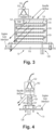
Fig. 2 is a schematic view of the pressure sensor system ofFig. 1 , showing the tube connecting the manifold flange in fluid communication with the case flange; -
Fig. 3 is a schematic view of the pressure sensor system ofFig. 2 , showing a tube as a labyrinthine part of a heat exchanger; and -
Fig. 4 is a lateral view of the system ofFig. 3 , showing the second third dimension of the labyrinthine passage of the tube. - Reference will now be made to the drawings wherein like reference numerals identify similar structural features or aspects of the subject disclosure. For purposes of explanation and illustration, and not limitation, a partial view of an embodiment of a system in accordance with the disclosure is shown in
Fig. 1 and is designated generally byreference character 100. Other embodiments of systems in accordance with the disclosure, or aspects thereof, are provided inFigs. 2-4 , as will be described. The systems and methods described herein can be used to provide pressure sensors that avoid high temperature flow reaching sensitive component, counteracting potential installation errors or variations. - A gas
turbine engine system 10 includes acompressor section 12 that supplies pressurized air to acombustor 14 downstream thereof. The combustor adds heat and combustion products to the pressurized air to drive adownstream turbine section 16. Theturbine section 16 mechanically drives thecompressor section 12. Anacelle 18 houses thecompressor section 12, thecombustor 14, and theturbine section 16. A first gas path is defined through thecompressor section 12, thecombustor 14, and theturbine section 16. A second,separate gas path 20 is defined through thenacelle 18 outboard of thecompressor section 12,combustor 14, andturbine section 16. Theengine system 10 includes apressure sensing system 100. - With reference now to
Fig. 2 , thepressure sensing system 100 includes ahousing 102 that houses one ormore pressure transducers 104 therein. Thehousing 102 includes amanifold flange 106 with the one ormore pressure transducers 104 in fluid communication withrespective ports 108 in themanifold flange 106. Atube 110 is integral with themanifold flange 106 at afirst end 111 of thetube 110. Therespective ports 108 in themanifold flange 106 are each in fluid communication with aninner passage 112 of thetube 110. The one ormore pressure transducers 104 are in fluid communication with asecond end 113 of thetube 110 through theinner passage 112 for sensing pressure at thesecond end 113 of thetube 110. Thehousing 102 includes anenclosure case 114 mounted, e.g., welded, to themanifold flange 106 to enclose the one ormore pressure transducers 104. - A
case flange 116 is mounted, e.g. bolted, to theengine case 13, i.e. the compressor case of thecompressor section 12 inFig. 1 . The case flange 116 includes aninner passage 118 therethrough in fluid communication with aninterior flow path 120 of theengine case 13. The case flange 116 is connected with itsinner passage 118 in fluid communication withinner passage 112 at thesecond end 113 of thetube 110. This provides fluid communication of pressure from theinterior flow path 120 of theengine case 13, through thecase flange 116, through theinner passage 112 of thetube 110, and through theports 108 in themanifold flange 106, for pressure sensing pressure in theengine case 13 by the one ormore pressure transducers 104. - The tube is sealed, e.g. with a polymeric seal, or by being integral as described below, with the
manifold flange 106, so there is no AN (Army/Navy standard) flair fitting joint connecting thetube 110 to thehousing 102. Instead of a polymeric seal sealing between thetube 110 and themanifold flange 106, thetube 110 can be welded to themanifold flange 106 at a weld joint that fully seals therespective ports 108 and theinner passage 112 of thetube 110 in fluid communication with one another. It is also contemplated that thetube 110 and themanifold flange 106 can be metallurgically monolithic, i.e. with no weld or heat effected zone connecting the two, e.g. wherein thetube 110 and themanifold flange 106 are additively manufactured or machined as one piece. Thehousing 102 includes aharness 122 electrically connected to the one ormore pressure transducers 104 for electrical communication of signals from the one ormore pressure transducers 104 to engine control components through thehousing 102. - With reference now to
Fig. 3 , it is contemplated that thetube 110 can define a labyrinthine path through aheat exchanger 124. The labyrinthine structure can function to improve heat transfer and reduce or minimize the packaging. Theheat exchanger 124 includesfins 126 radiating outward therefrom for heat exchange with nacelle air in the nacelle 18 (labeled inFig. 1 ) outboard of theengine case 13, as indicated by the flow arrows inFig. 3 . The case flange 116 can be connected in fluid communication with theengine case 13 through a fitting joint 128, e.g. an AN (Army/Navy standard) flair fitting joint or the like.Fig. 4 shows the pressure sensor system ofFig. 3 from the lateral side to show that the labyrinthine path of thetube 110 can be labyrinthine in three dimensions. - Systems and methods as disclosed herein provide potential benefits including the following. They can prevent high temperature air leakage at the sensor and can improve mean time between failures (MTBF). They can simplify sensor installation and provide an improved packaging footprint. They can potentially be additively manufactured, and are simple, reliable, and robust. Heat exchanger fins cooled by nacelle air allows for lower temperature air from compressor reaching the sensor. This reduces temperature of the sensor.
- The methods and systems of the present disclosure, as described above and shown in the drawings, provide for pressure sensors that avoid high temperature flow reaching sensitive component, counteracting potential installation errors or variations. While the apparatus and methods of the subject disclosure have been shown and described with reference to preferred embodiments, those skilled in the art will readily appreciate that changes and/or modifications may be made thereto without departing from the scope of the subject disclosure.
Claims (15)
- A pressure sensing system comprising:a housing (102) that houses one or more pressure transducers (104) therein;a tube (110) sealed to the housing at a first end (111) of the tube; andone or more pressure transducers in fluid communication with a second end (113) of the tube through an inner passage (118) of the tube for sensing pressure at the second end of the tube.
- The system as recited in claim 1, wherein the housing (102) includes a manifold flange (106) with one or more pressure transducers (104) in fluid communication with respective ports in the manifold flange.
- The system as recited in claim 2, wherein the tube (110) is integral with the manifold flange (106).
- The system as recited in claim 3, wherein the tube (110) is welded to the manifold flange (106) at a weld joint that fully seals the respective ports and the inner passage (118) of the tube (110) in fluid communication with one another.
- The system as recited in claim 3, wherein the tube (110) and the manifold flange (106) are metallurgically monolithic.
- The system as recited in claim 5, wherein the tube (110) and the manifold flange (106) are additively manufactured as one piece; or wherein the tube (110) and the manifold flange (106) are machined as a single piece.
- The system as recited in claim 3, wherein the respective ports in the manifold flange (106) are each in fluid communication with the inner passage (118) of the tube (110); and optionally:
wherein the system further comprises a case flange (116) configured to be mounted to a compressor case (13) in fluid communication with an interior flow path (120) of the compressor case, wherein the case flange is connected in fluid communication with the second end (113) of the tube (110) for fluid communication of pressure from the interior flow path of the compressor case, through the case flange, through the inner passage of the tube, and through the ports in the manifold flange, for pressure sensing pressure in the compressor case by the one or more pressure transducers (104). - The system as recited in any preceding claim, wherein the housing (102) includes an enclosure case (114) mounted to the manifold flange (106) to enclose the one or more pressure transducers (104).
- The system as recited in any preceding claim, wherein the tube (110) defines a labyrinthine path through a heat exchanger (124); and optionally wherein the heat exchanger includes fins (126) radiating outward therefrom for heat exchange with nacelle air external from the tube and heat exchanger.
- The system as recited in any preceding claim, wherein the housing (102) includes a harness (122) for electrical communication of signals from the one or more pressure transducers (104) to engine control components through the housing.
- A gas turbine engine system comprising:an engine case (13);a housing (102) that houses one or more pressure transducers (104) therein, wherein the housing includes a manifold flange (106) with the one or more pressure transducers in fluid communication with respective ports in the manifold flange;a tube (110) sealed to the manifold flange at a first end (111) of the tube, wherein the respective ports in the manifold flange are each in fluid communication with an inner passage (118) of the tube, wherein the one or more pressure transducers are in fluid communication with a second end (113) of the tube through the inner passage of the tube for sensing pressure at the second end of the tube; anda case flange (116) configured to be mounted to the engine case in fluid communication with an interior flow path of the engine case, wherein the case flange is connected in fluid communication with the second end of the tube for fluid communication of pressure from the interior flow path of the engine case, through the case flange, through the inner passage of the tube, and through the ports in the manifold flange, for pressure sensing pressure in the engine case by the one or more pressure transducers.
- The system as recited in claim 11, wherein the housing (102) includes an enclosure case (114) mounted to the manifold flange (106) to enclose the one or more pressure transducers (104).
- The system as recited in claim 11 or 12, wherein the tube (110) defines a labyrinthine path through a heat exchanger (124); and optionally wherein the heat exchanger includes fins (126) radiating outward therefrom for heat exchange with nacelle air in a nacelle outboard of the engine case (13).
- The system as recited in claim 11, 12 or 13, wherein the engine case (13) is a compressor case of a compressor section upstream of a combustor that is upstream of a turbine section.
- The system as recited in claim 11, 12, 13 or 14, wherein the housing (102) includes a harness (122) for electrical communication of signals from the one or more pressure transducers (104) to engine control components through the housing; and/or wherein the case flange (116) is connected in fluid communication with the engine case (13) through a fitting joint.
Applications Claiming Priority (1)
| Application Number | Priority Date | Filing Date | Title |
|---|---|---|---|
| US18/238,811 US12631510B2 (en) | 2023-08-28 | 2023-08-28 | Pressure sensor manifolds for high temperatures |
Publications (2)
| Publication Number | Publication Date |
|---|---|
| EP4517288A1 true EP4517288A1 (en) | 2025-03-05 |
| EP4517288B1 EP4517288B1 (en) | 2026-02-25 |
Family
ID=92583142
Family Applications (1)
| Application Number | Title | Priority Date | Filing Date |
|---|---|---|---|
| EP24196817.1A Active EP4517288B1 (en) | 2023-08-28 | 2024-08-27 | Pressure sensor manifolds for high temperatures |
Country Status (2)
| Country | Link |
|---|---|
| US (1) | US12631510B2 (en) |
| EP (1) | EP4517288B1 (en) |
Citations (5)
| Publication number | Priority date | Publication date | Assignee | Title |
|---|---|---|---|---|
| US6508129B1 (en) * | 2000-01-06 | 2003-01-21 | Rosemount Inc. | Pressure sensor capsule with improved isolation |
| US8733078B2 (en) * | 2010-11-10 | 2014-05-27 | United Technologies Corporation | Igniter with integral pressure sensing line |
| US20200355568A1 (en) * | 2019-05-06 | 2020-11-12 | Rosemount Aerospace Inc. | Pressure transducer including kovar integrated packages |
| US20220235715A1 (en) * | 2021-01-27 | 2022-07-28 | General Electric Company | System and method for fault sensing flow components |
| US11549446B1 (en) * | 2022-02-04 | 2023-01-10 | Pratt & Whitney Canada Corp. | Method and apparatus for measuring compressor bleed flow |
Family Cites Families (11)
| Publication number | Priority date | Publication date | Assignee | Title |
|---|---|---|---|---|
| US4151710A (en) | 1977-03-11 | 1979-05-01 | United Technologies Corporation | Lubrication cooling system for aircraft engine accessory |
| US4759401A (en) | 1984-11-29 | 1988-07-26 | Parker-Hannifin Corporation | Three fluid heat exchanger for cooling oil and air with fuel |
| US5090740A (en) | 1989-03-01 | 1992-02-25 | Creager Richard F | Integral manifold |
| US6189313B1 (en) | 1999-04-16 | 2001-02-20 | Hamilton Sundstrand Corporation | Aircraft engine fuel system mounting assembly |
| US7836680B2 (en) | 2007-06-20 | 2010-11-23 | United Technologies Corporation | Aircraft combination engines thermal management system |
| US8262344B2 (en) | 2008-04-02 | 2012-09-11 | Hamilton Sundstrand Corporation | Thermal management system for a gas turbine engine |
| FR2960596B1 (en) * | 2010-05-25 | 2014-05-02 | Turbomeca | DEVICE FOR THE MULTIPURPOSE ACQUISITION / DISTRIBUTION OF FLUID, IN PARTICULAR PRESSURE TAKING PROBE IN A TURBOMACHINE AIR INLET |
| EP3008311A4 (en) * | 2013-06-12 | 2016-07-20 | United Technologies Corp | Fuel/oil manifold |
| US10253693B2 (en) | 2013-10-09 | 2019-04-09 | United Technologies Corporation | Thermal management system manifold |
| US10544717B2 (en) | 2016-09-07 | 2020-01-28 | Pratt & Whitney Canada Corp. | Shared oil system arrangement for an engine component and a generator |
| US11649056B2 (en) * | 2020-06-17 | 2023-05-16 | Honeywell International Inc. | Thermally isolated sensor for gas turbine engine |
-
2023
- 2023-08-28 US US18/238,811 patent/US12631510B2/en active Active
-
2024
- 2024-08-27 EP EP24196817.1A patent/EP4517288B1/en active Active
Patent Citations (5)
| Publication number | Priority date | Publication date | Assignee | Title |
|---|---|---|---|---|
| US6508129B1 (en) * | 2000-01-06 | 2003-01-21 | Rosemount Inc. | Pressure sensor capsule with improved isolation |
| US8733078B2 (en) * | 2010-11-10 | 2014-05-27 | United Technologies Corporation | Igniter with integral pressure sensing line |
| US20200355568A1 (en) * | 2019-05-06 | 2020-11-12 | Rosemount Aerospace Inc. | Pressure transducer including kovar integrated packages |
| US20220235715A1 (en) * | 2021-01-27 | 2022-07-28 | General Electric Company | System and method for fault sensing flow components |
| US11549446B1 (en) * | 2022-02-04 | 2023-01-10 | Pratt & Whitney Canada Corp. | Method and apparatus for measuring compressor bleed flow |
Also Published As
| Publication number | Publication date |
|---|---|
| US12631510B2 (en) | 2026-05-19 |
| US20250076142A1 (en) | 2025-03-06 |
| EP4517288B1 (en) | 2026-02-25 |
Similar Documents
| Publication | Publication Date | Title |
|---|---|---|
| US8079220B2 (en) | Fuel distribution manifold system for gas turbine engines | |
| CN100456008C (en) | Pressure transmitter module with leak-proof sensor housing | |
| US5263314A (en) | Fuel leakage protection system for gas turbine engine | |
| EP3828399B1 (en) | Internal fuel/air heat exchangers | |
| CN100472115C (en) | Capillary welded extension with thermal insulation | |
| EP4105468B1 (en) | Sweep flow structures for fuel systems | |
| US8196845B2 (en) | Flexure seal for fuel injection nozzle | |
| CN102564464B (en) | For the system and method for alignment sensor | |
| EP2902605B1 (en) | A fuel manifold and fuel injector arrangement for a gas turbine engine | |
| US6843061B2 (en) | Gas turbine with flexible combustion sensor connection | |
| EP2042691A2 (en) | Lubricant pipe assembly for a turbine | |
| CN111811822B (en) | Measuring structure, connecting device, combustion chamber and combustion chamber test system for flame tube wall static pressure | |
| US4047740A (en) | Internally insulated bellows assembly | |
| US9032735B2 (en) | Combustor and a method for assembling the combustor | |
| EP3597867B1 (en) | Sealing configuration using a bellows to reduce air leakage | |
| CN207194961U (en) | A kind of turbine shaft seal steam temperature control system | |
| EP4517288B1 (en) | Pressure sensor manifolds for high temperatures | |
| EP4137689A1 (en) | Air manifolds for fuel injectors with fuel air heat exchangers | |
| CN111656075A (en) | Flange assembly | |
| CN113309637B (en) | Double tube structure, support, and method for forming double tube structure | |
| CN116539314A (en) | Measurement and installation structure for total temperature and total pressure sensing part of turbine outlet of aeroengine | |
| JP6149754B2 (en) | Thermoelectric generator | |
| EP3171144B1 (en) | Gas turbine engine comprising a sealed and actively cooled instrumentation egress, and method for sealing an actively cooled instrumentation egress | |
| EP3073168B1 (en) | Double wall tube fitting with an integrated diagnostic port | |
| JP4672565B2 (en) | Temperature measuring device, combustion monitoring device, and gas turbine |
Legal Events
| Date | Code | Title | Description |
|---|---|---|---|
| PUAI | Public reference made under article 153(3) epc to a published international application that has entered the european phase |
Free format text: ORIGINAL CODE: 0009012 |
|
| STAA | Information on the status of an ep patent application or granted ep patent |
Free format text: STATUS: THE APPLICATION HAS BEEN PUBLISHED |
|
| AK | Designated contracting states |
Kind code of ref document: A1 Designated state(s): AL AT BE BG CH CY CZ DE DK EE ES FI FR GB GR HR HU IE IS IT LI LT LU LV MC ME MK MT NL NO PL PT RO RS SE SI SK SM TR |
|
| STAA | Information on the status of an ep patent application or granted ep patent |
Free format text: STATUS: REQUEST FOR EXAMINATION WAS MADE |
|
| GRAP | Despatch of communication of intention to grant a patent |
Free format text: ORIGINAL CODE: EPIDOSNIGR1 |
|
| STAA | Information on the status of an ep patent application or granted ep patent |
Free format text: STATUS: GRANT OF PATENT IS INTENDED |
|
| 17P | Request for examination filed |
Effective date: 20250903 |
|
| INTG | Intention to grant announced |
Effective date: 20251006 |
|
| GRAS | Grant fee paid |
Free format text: ORIGINAL CODE: EPIDOSNIGR3 |
|
| GRAA | (expected) grant |
Free format text: ORIGINAL CODE: 0009210 |
|
| STAA | Information on the status of an ep patent application or granted ep patent |
Free format text: STATUS: THE PATENT HAS BEEN GRANTED |
|
| AK | Designated contracting states |
Kind code of ref document: B1 Designated state(s): AL AT BE BG CH CY CZ DE DK EE ES FI FR GB GR HR HU IE IS IT LI LT LU LV MC ME MK MT NL NO PL PT RO RS SE SI SK SM TR |
|
| REG | Reference to a national code |
Ref country code: CH Ref legal event code: F10 Free format text: ST27 STATUS EVENT CODE: U-0-0-F10-F00 (AS PROVIDED BY THE NATIONAL OFFICE) Effective date: 20260225 Ref country code: GB Ref legal event code: FG4D |
|
| REG | Reference to a national code |
Ref country code: DE Ref legal event code: R096 Ref document number: 602024002807 Country of ref document: DE |
|
| REG | Reference to a national code |
Ref country code: IE Ref legal event code: FG4D |
|
| REG | Reference to a national code |
Ref country code: NL Ref legal event code: MP Effective date: 20260225 |
|
| PG25 | Lapsed in a contracting state [announced via postgrant information from national office to epo] |
Ref country code: RS Free format text: LAPSE BECAUSE OF FAILURE TO SUBMIT A TRANSLATION OF THE DESCRIPTION OR TO PAY THE FEE WITHIN THE PRESCRIBED TIME-LIMIT Effective date: 20260525 |
|
| PG25 | Lapsed in a contracting state [announced via postgrant information from national office to epo] |
Ref country code: ES Free format text: LAPSE BECAUSE OF FAILURE TO SUBMIT A TRANSLATION OF THE DESCRIPTION OR TO PAY THE FEE WITHIN THE PRESCRIBED TIME-LIMIT Effective date: 20260225 |
|
| PG25 | Lapsed in a contracting state [announced via postgrant information from national office to epo] |
Ref country code: PL Free format text: LAPSE BECAUSE OF FAILURE TO SUBMIT A TRANSLATION OF THE DESCRIPTION OR TO PAY THE FEE WITHIN THE PRESCRIBED TIME-LIMIT Effective date: 20260225 |
|
| PG25 | Lapsed in a contracting state [announced via postgrant information from national office to epo] |
Ref country code: GR Free format text: LAPSE BECAUSE OF FAILURE TO SUBMIT A TRANSLATION OF THE DESCRIPTION OR TO PAY THE FEE WITHIN THE PRESCRIBED TIME-LIMIT Effective date: 20260526 |
|
| REG | Reference to a national code |
Ref country code: LT Ref legal event code: MG9D |
|
| PG25 | Lapsed in a contracting state [announced via postgrant information from national office to epo] |
Ref country code: LT Free format text: LAPSE BECAUSE OF FAILURE TO SUBMIT A TRANSLATION OF THE DESCRIPTION OR TO PAY THE FEE WITHIN THE PRESCRIBED TIME-LIMIT Effective date: 20260225 |
|
| PG25 | Lapsed in a contracting state [announced via postgrant information from national office to epo] |
Ref country code: NO Free format text: LAPSE BECAUSE OF FAILURE TO SUBMIT A TRANSLATION OF THE DESCRIPTION OR TO PAY THE FEE WITHIN THE PRESCRIBED TIME-LIMIT Effective date: 20260525 |
|
| PG25 | Lapsed in a contracting state [announced via postgrant information from national office to epo] |
Ref country code: SE Free format text: LAPSE BECAUSE OF FAILURE TO SUBMIT A TRANSLATION OF THE DESCRIPTION OR TO PAY THE FEE WITHIN THE PRESCRIBED TIME-LIMIT Effective date: 20260225 Ref country code: AT Free format text: LAPSE BECAUSE OF FAILURE TO SUBMIT A TRANSLATION OF THE DESCRIPTION OR TO PAY THE FEE WITHIN THE PRESCRIBED TIME-LIMIT Effective date: 20260225 Ref country code: FI Free format text: LAPSE BECAUSE OF FAILURE TO SUBMIT A TRANSLATION OF THE DESCRIPTION OR TO PAY THE FEE WITHIN THE PRESCRIBED TIME-LIMIT Effective date: 20260225 |
|
| REG | Reference to a national code |
Ref country code: AT Ref legal event code: MK05 Ref document number: 1891306 Country of ref document: AT Kind code of ref document: T Effective date: 20260225 |
|
| PG25 | Lapsed in a contracting state [announced via postgrant information from national office to epo] |
Ref country code: HR Free format text: LAPSE BECAUSE OF FAILURE TO SUBMIT A TRANSLATION OF THE DESCRIPTION OR TO PAY THE FEE WITHIN THE PRESCRIBED TIME-LIMIT Effective date: 20260225 |
|
| PG25 | Lapsed in a contracting state [announced via postgrant information from national office to epo] |
Ref country code: IS Free format text: LAPSE BECAUSE OF FAILURE TO SUBMIT A TRANSLATION OF THE DESCRIPTION OR TO PAY THE FEE WITHIN THE PRESCRIBED TIME-LIMIT Effective date: 20260625 Ref country code: PT Free format text: LAPSE BECAUSE OF FAILURE TO SUBMIT A TRANSLATION OF THE DESCRIPTION OR TO PAY THE FEE WITHIN THE PRESCRIBED TIME-LIMIT Effective date: 20260625 |
|
| PG25 | Lapsed in a contracting state [announced via postgrant information from national office to epo] |
Ref country code: NL Free format text: LAPSE BECAUSE OF FAILURE TO SUBMIT A TRANSLATION OF THE DESCRIPTION OR TO PAY THE FEE WITHIN THE PRESCRIBED TIME-LIMIT Effective date: 20260225 |
|
| PG25 | Lapsed in a contracting state [announced via postgrant information from national office to epo] |
Ref country code: LV Free format text: LAPSE BECAUSE OF FAILURE TO SUBMIT A TRANSLATION OF THE DESCRIPTION OR TO PAY THE FEE WITHIN THE PRESCRIBED TIME-LIMIT Effective date: 20260225 |
|
| PG25 | Lapsed in a contracting state [announced via postgrant information from national office to epo] |
Ref country code: BG Free format text: LAPSE BECAUSE OF FAILURE TO SUBMIT A TRANSLATION OF THE DESCRIPTION OR TO PAY THE FEE WITHIN THE PRESCRIBED TIME-LIMIT Effective date: 20260225 |