EP4517155A1 - Compressor unit - Google Patents
Compressor unit Download PDFInfo
- Publication number
- EP4517155A1 EP4517155A1 EP23815713.5A EP23815713A EP4517155A1 EP 4517155 A1 EP4517155 A1 EP 4517155A1 EP 23815713 A EP23815713 A EP 23815713A EP 4517155 A1 EP4517155 A1 EP 4517155A1
- Authority
- EP
- European Patent Office
- Prior art keywords
- temperature
- hydrogen gas
- compressor
- routing section
- suction
- Prior art date
- Legal status (The legal status is an assumption and is not a legal conclusion. Google has not performed a legal analysis and makes no representation as to the accuracy of the status listed.)
- Pending
Links
Images






Classifications
-
- F—MECHANICAL ENGINEERING; LIGHTING; HEATING; WEAPONS; BLASTING
- F04—POSITIVE - DISPLACEMENT MACHINES FOR LIQUIDS; PUMPS FOR LIQUIDS OR ELASTIC FLUIDS
- F04B—POSITIVE-DISPLACEMENT MACHINES FOR LIQUIDS; PUMPS
- F04B37/00—Pumps having pertinent characteristics not provided for in, or of interest apart from, groups F04B25/00 - F04B35/00
- F04B37/10—Pumps having pertinent characteristics not provided for in, or of interest apart from, groups F04B25/00 - F04B35/00 for special use
- F04B37/18—Pumps having pertinent characteristics not provided for in, or of interest apart from, groups F04B25/00 - F04B35/00 for special use for specific elastic fluids
-
- F—MECHANICAL ENGINEERING; LIGHTING; HEATING; WEAPONS; BLASTING
- F04—POSITIVE - DISPLACEMENT MACHINES FOR LIQUIDS; PUMPS FOR LIQUIDS OR ELASTIC FLUIDS
- F04B—POSITIVE-DISPLACEMENT MACHINES FOR LIQUIDS; PUMPS
- F04B39/00—Component parts, details, or accessories, of pumps or pumping systems specially adapted for elastic fluids, not otherwise provided for in, or of interest apart from, groups F04B25/00 - F04B37/00
- F04B39/06—Cooling; Heating; Prevention of freezing
-
- F—MECHANICAL ENGINEERING; LIGHTING; HEATING; WEAPONS; BLASTING
- F04—POSITIVE - DISPLACEMENT MACHINES FOR LIQUIDS; PUMPS FOR LIQUIDS OR ELASTIC FLUIDS
- F04B—POSITIVE-DISPLACEMENT MACHINES FOR LIQUIDS; PUMPS
- F04B39/00—Component parts, details, or accessories, of pumps or pumping systems specially adapted for elastic fluids, not otherwise provided for in, or of interest apart from, groups F04B25/00 - F04B37/00
- F04B39/08—Actuation of distribution members
-
- F—MECHANICAL ENGINEERING; LIGHTING; HEATING; WEAPONS; BLASTING
- F04—POSITIVE - DISPLACEMENT MACHINES FOR LIQUIDS; PUMPS FOR LIQUIDS OR ELASTIC FLUIDS
- F04B—POSITIVE-DISPLACEMENT MACHINES FOR LIQUIDS; PUMPS
- F04B39/00—Component parts, details, or accessories, of pumps or pumping systems specially adapted for elastic fluids, not otherwise provided for in, or of interest apart from, groups F04B25/00 - F04B37/00
- F04B39/12—Casings; Cylinders; Cylinder heads; Fluid connections
-
- F—MECHANICAL ENGINEERING; LIGHTING; HEATING; WEAPONS; BLASTING
- F04—POSITIVE - DISPLACEMENT MACHINES FOR LIQUIDS; PUMPS FOR LIQUIDS OR ELASTIC FLUIDS
- F04B—POSITIVE-DISPLACEMENT MACHINES FOR LIQUIDS; PUMPS
- F04B41/00—Pumping installations or systems specially adapted for elastic fluids
- F04B41/02—Pumping installations or systems specially adapted for elastic fluids having reservoirs
-
- F—MECHANICAL ENGINEERING; LIGHTING; HEATING; WEAPONS; BLASTING
- F04—POSITIVE - DISPLACEMENT MACHINES FOR LIQUIDS; PUMPS FOR LIQUIDS OR ELASTIC FLUIDS
- F04B—POSITIVE-DISPLACEMENT MACHINES FOR LIQUIDS; PUMPS
- F04B49/00—Control, e.g. of pump delivery, or pump pressure of, or safety measures for, machines, pumps, or pumping installations, not otherwise provided for, or of interest apart from, groups F04B1/00 - F04B47/00
- F04B49/06—Control using electricity
-
- F—MECHANICAL ENGINEERING; LIGHTING; HEATING; WEAPONS; BLASTING
- F04—POSITIVE - DISPLACEMENT MACHINES FOR LIQUIDS; PUMPS FOR LIQUIDS OR ELASTIC FLUIDS
- F04B—POSITIVE-DISPLACEMENT MACHINES FOR LIQUIDS; PUMPS
- F04B49/00—Control, e.g. of pump delivery, or pump pressure of, or safety measures for, machines, pumps, or pumping installations, not otherwise provided for, or of interest apart from, groups F04B1/00 - F04B47/00
- F04B49/06—Control using electricity
- F04B49/065—Control using electricity and making use of computers
-
- F—MECHANICAL ENGINEERING; LIGHTING; HEATING; WEAPONS; BLASTING
- F04—POSITIVE - DISPLACEMENT MACHINES FOR LIQUIDS; PUMPS FOR LIQUIDS OR ELASTIC FLUIDS
- F04B—POSITIVE-DISPLACEMENT MACHINES FOR LIQUIDS; PUMPS
- F04B49/00—Control, e.g. of pump delivery, or pump pressure of, or safety measures for, machines, pumps, or pumping installations, not otherwise provided for, or of interest apart from, groups F04B1/00 - F04B47/00
- F04B49/22—Control, e.g. of pump delivery, or pump pressure of, or safety measures for, machines, pumps, or pumping installations, not otherwise provided for, or of interest apart from, groups F04B1/00 - F04B47/00 by means of valves
-
- F—MECHANICAL ENGINEERING; LIGHTING; HEATING; WEAPONS; BLASTING
- F04—POSITIVE - DISPLACEMENT MACHINES FOR LIQUIDS; PUMPS FOR LIQUIDS OR ELASTIC FLUIDS
- F04B—POSITIVE-DISPLACEMENT MACHINES FOR LIQUIDS; PUMPS
- F04B49/00—Control, e.g. of pump delivery, or pump pressure of, or safety measures for, machines, pumps, or pumping installations, not otherwise provided for, or of interest apart from, groups F04B1/00 - F04B47/00
- F04B49/22—Control, e.g. of pump delivery, or pump pressure of, or safety measures for, machines, pumps, or pumping installations, not otherwise provided for, or of interest apart from, groups F04B1/00 - F04B47/00 by means of valves
- F04B49/225—Control, e.g. of pump delivery, or pump pressure of, or safety measures for, machines, pumps, or pumping installations, not otherwise provided for, or of interest apart from, groups F04B1/00 - F04B47/00 by means of valves with throttling valves or valves varying the pump inlet opening or the outlet opening
-
- F—MECHANICAL ENGINEERING; LIGHTING; HEATING; WEAPONS; BLASTING
- F17—STORING OR DISTRIBUTING GASES OR LIQUIDS
- F17C—VESSELS FOR CONTAINING OR STORING COMPRESSED, LIQUEFIED OR SOLIDIFIED GASES; FIXED-CAPACITY GAS-HOLDERS; FILLING VESSELS WITH, OR DISCHARGING FROM VESSELS, COMPRESSED, LIQUEFIED, OR SOLIDIFIED GASES
- F17C13/00—Details of vessels or of the filling or discharging of vessels
-
- F—MECHANICAL ENGINEERING; LIGHTING; HEATING; WEAPONS; BLASTING
- F04—POSITIVE - DISPLACEMENT MACHINES FOR LIQUIDS; PUMPS FOR LIQUIDS OR ELASTIC FLUIDS
- F04B—POSITIVE-DISPLACEMENT MACHINES FOR LIQUIDS; PUMPS
- F04B15/00—Pumps adapted to handle specific fluids, e.g. by selection of specific materials for pumps or pump parts
- F04B15/06—Pumps adapted to handle specific fluids, e.g. by selection of specific materials for pumps or pump parts for liquids near their boiling point, e.g. under subnormal pressure
- F04B15/08—Pumps adapted to handle specific fluids, e.g. by selection of specific materials for pumps or pump parts for liquids near their boiling point, e.g. under subnormal pressure the liquids having low boiling points
-
- F—MECHANICAL ENGINEERING; LIGHTING; HEATING; WEAPONS; BLASTING
- F04—POSITIVE - DISPLACEMENT MACHINES FOR LIQUIDS; PUMPS FOR LIQUIDS OR ELASTIC FLUIDS
- F04B—POSITIVE-DISPLACEMENT MACHINES FOR LIQUIDS; PUMPS
- F04B2205/00—Fluid parameters
- F04B2205/10—Inlet temperature
-
- F—MECHANICAL ENGINEERING; LIGHTING; HEATING; WEAPONS; BLASTING
- F17—STORING OR DISTRIBUTING GASES OR LIQUIDS
- F17C—VESSELS FOR CONTAINING OR STORING COMPRESSED, LIQUEFIED OR SOLIDIFIED GASES; FIXED-CAPACITY GAS-HOLDERS; FILLING VESSELS WITH, OR DISCHARGING FROM VESSELS, COMPRESSED, LIQUEFIED, OR SOLIDIFIED GASES
- F17C2221/00—Handled fluid, in particular type of fluid
- F17C2221/01—Pure fluids
- F17C2221/012—Hydrogen
-
- F—MECHANICAL ENGINEERING; LIGHTING; HEATING; WEAPONS; BLASTING
- F17—STORING OR DISTRIBUTING GASES OR LIQUIDS
- F17C—VESSELS FOR CONTAINING OR STORING COMPRESSED, LIQUEFIED OR SOLIDIFIED GASES; FIXED-CAPACITY GAS-HOLDERS; FILLING VESSELS WITH, OR DISCHARGING FROM VESSELS, COMPRESSED, LIQUEFIED, OR SOLIDIFIED GASES
- F17C2227/00—Transfer of fluids, i.e. method or means for transferring the fluid; Heat exchange with the fluid
- F17C2227/01—Propulsion of the fluid
- F17C2227/0128—Propulsion of the fluid with pumps or compressors
- F17C2227/0157—Compressors
-
- F—MECHANICAL ENGINEERING; LIGHTING; HEATING; WEAPONS; BLASTING
- F17—STORING OR DISTRIBUTING GASES OR LIQUIDS
- F17C—VESSELS FOR CONTAINING OR STORING COMPRESSED, LIQUEFIED OR SOLIDIFIED GASES; FIXED-CAPACITY GAS-HOLDERS; FILLING VESSELS WITH, OR DISCHARGING FROM VESSELS, COMPRESSED, LIQUEFIED, OR SOLIDIFIED GASES
- F17C2265/00—Effects achieved by gas storage or gas handling
- F17C2265/03—Treating the boil-off
- F17C2265/032—Treating the boil-off by recovery
- F17C2265/037—Treating the boil-off by recovery with pressurising
-
- F—MECHANICAL ENGINEERING; LIGHTING; HEATING; WEAPONS; BLASTING
- F17—STORING OR DISTRIBUTING GASES OR LIQUIDS
- F17C—VESSELS FOR CONTAINING OR STORING COMPRESSED, LIQUEFIED OR SOLIDIFIED GASES; FIXED-CAPACITY GAS-HOLDERS; FILLING VESSELS WITH, OR DISCHARGING FROM VESSELS, COMPRESSED, LIQUEFIED, OR SOLIDIFIED GASES
- F17C2265/00—Effects achieved by gas storage or gas handling
- F17C2265/07—Generating electrical power as side effect
-
- Y—GENERAL TAGGING OF NEW TECHNOLOGICAL DEVELOPMENTS; GENERAL TAGGING OF CROSS-SECTIONAL TECHNOLOGIES SPANNING OVER SEVERAL SECTIONS OF THE IPC; TECHNICAL SUBJECTS COVERED BY FORMER USPC CROSS-REFERENCE ART COLLECTIONS [XRACs] AND DIGESTS
- Y02—TECHNOLOGIES OR APPLICATIONS FOR MITIGATION OR ADAPTATION AGAINST CLIMATE CHANGE
- Y02E—REDUCTION OF GREENHOUSE GAS [GHG] EMISSIONS, RELATED TO ENERGY GENERATION, TRANSMISSION OR DISTRIBUTION
- Y02E60/00—Enabling technologies; Technologies with a potential or indirect contribution to GHG emissions mitigation
- Y02E60/30—Hydrogen technology
Definitions
- the present invention relates to a compressor unit.
- low-temperature boil-off gas such as liquefied natural gas (LNG) and liquid hydrogen (LH2) is recovered by a compressor and supplied to demand destinations such as engines.
- LNG liquefied natural gas
- LH2 liquid hydrogen
- the boil-off gas generated from LH2 has a very low temperature. Therefore, if a configuration is adopted in which the compressor directly suctions in the boil-off gas, restrictions will be imposed, such as it is necessary to select materials suitable for extremely low temperatures, adopt design conditions that take into account the amount of thermal deformation, and implement strict heat insulation treatment.
- Patent Literature 1 In recent years, hydrogen has been attracting attention as a new energy source. When hydrogen is used as an energy source, it is assumed that hydrogen will be stored and transported in a liquefied state, like natural gas. However, hydrogen has the property that the liquefaction temperature is lower than the liquefaction temperature of air. Therefore, if facilities such as reciprocating compressors for natural gas and other gases are applied to hydrogen as is, there is a possibility of a trouble caused by cryogenic liquid hydrogen. For example, this may generate liquefied air around the apparatus that is supplied with liquid hydrogen.”
- Patent Literature 1 the problem of preventing troubles caused by cryogenic liquid hydrogen is studied.
- pipes that are easy to install high-performance heat insulation for example, those with a vacuum area
- high-performance insulation can be very difficult to install in some apparatuses, such as a machine that vibrates during operation and equipment that requires regular maintenance through inspection openings (such as reciprocating compressors, for example).
- Patent Literatures 2 to 4 it is known to provide a heat exchanger capable of heating a boil-off gas before being suctioned into a compressor. Meanwhile, if the suctioned gas is heated excessively, the expansion of the gas volume increases the compression power and results in a loss of power (energy). Therefore, it is required to control the suction temperature within an appropriate range.
- a heat exchanger 104 that heats a boil-off gas before being suctioned into a compressor part 102 with the boil-off gas discharged from the compressor part 102.
- This compressor unit can change the flow rate that flows through the heat exchanger 104 depending on the gas processing volume.
- the flow rate can only be changed in the heat exchanger 104 depending on the gas processing volume in the compressor part 102. Therefore, it is not possible to adjust the flow rate flowing through the heat exchanger 104 such that the gas temperature suctioned into the compressor part 102 becomes a predetermined temperature.
- the compressor unit disclosed in Patent Literature 3 below is provided with a bypass pipe 114 that bypasses the heat exchanger 112, as shown in FIG. 13 .
- a bypass pipe 114 that bypasses the heat exchanger 112
- the opening of the valve 114a it may be possible to adjust the temperature of the boil-off gas suctioned into the compressor part 116.
- the compressor unit of Patent Literature 3 even if the valve 114a is fully open, the boil-off gas may flow into the heat exchanger 112 due to pressure loss in the valve 114a itself. Therefore, it is difficult to control the gas temperature suctioned into the compressor part 116 so as to fall within an appropriate range.
- Patent Literature 4 also shows, as shown in FIG. 14 , a heat exchanger 123 that exchanges heat between the boil-off gas before being suctioned into the compressor part 121 and the boil-off gas after being discharged from the compressor part 121.
- this heat exchanger 123 is for re-liquefying the boil-off gas after being compressed in the compressor part 121. Therefore, the boil-off gas cooled by a cooler 125 disposed downstream of the compressor part 121 is introduced into the heat exchanger 123. Therefore, Patent Literature 4 is disadvantageous in terms of sufficiently heating the evaporated gas suctioned into the compressor part 121.
- Patent Literature 4 as in Patent Literature 3, since the temperature of the gas suctioned into the compressor part 121 is unlikely to become too high, there is no consideration to adjusting the temperature of the boil-off gas suctioned into the compressor part 121.
- An object of the present invention is to properly manage the temperature of the hydrogen gas that is a boil-off gas suctioned into a reciprocating compressor part in a compressor unit.
- a compressor unit is a compressor unit for recovering a hydrogen gas that is a boil-off gas from a liquid hydrogen storage tank, and supplying at least part of the hydrogen gas to a demand destination including at least one of an engine, a power generation facility, or a boiler.
- the first routing section passes through the preheater while the second routing section does not pass through the preheater.
- the compressor unit further includes: adjustment means configured to adjust a flow rate of the hydrogen gas flowing through the first routing section and adjust a flow rate of the hydrogen gas flowing through the second routing section; and a control unit configured to control the adjustment means such that a suction temperature that is a temperature of the hydrogen gas suctioned into the compressor part falls within a predetermined temperature range.
- the predetermined temperature range is higher than a reference temperature based on a liquefaction temperature of air.
- a compressor unit is configured to recover a hydrogen gas, which is a flammable boil-off gas below 0°C, from a liquid hydrogen storage tank, compress the recovered hydrogen gas, and supply the hydrogen gas to a demand destination.
- the boil-off gas which is a hydrogen gas, is at about -250°C. Examples of the demand destination include power generation equipment, boilers, and engines for ships or the like.
- the compressor part 12 is connected to a liquid hydrogen storage tank 23 via a suction channel 21. Therefore, the boil-off gas that is a liquefied gas generated inside the liquid hydrogen storage tank 23 is suctioned into the compressor part 12 through the suction channel 21.
- the compressor part 12 is configured by a reciprocating compressor mechanism. That is, as shown in FIG. 2 , the compressor part 12 includes a cylinder part 211, a piston 212, a piston rod 213, a pair of suction valves 214, and a pair of discharge valves 215.
- the piston 212 and the piston rod 213 are connected to a crank mechanism (not shown). By the piston 212 reciprocating inside the cylinder part 211, the hydrogen gas is compressed inside a compression chamber.
- FIG. 2 shows the compressor part 12 having a double acting structure, but the compressor part 12 may also have a single acting structure.
- FIG. 1 shows the compressor part 12 as a single trapezoid, but the compressor part 12 does not necessarily have to be a single stage compressor, but may include multiple compression stages. That is, the compressor part 12 may be configured such that the hydrogen gas is sequentially compressed and pressurized by the pistons 212 inside multiple cylinder parts 211 connected in series. The same applies to other embodiments described later.
- the suction channel 21 includes a heat insulating material 26 for suppressing heat input from the outside air. Note that the heat insulating material 26 may be omitted. In addition, a heat insulating material (not shown) may also be provided in a discharge channel 25 through which the hydrogen gas discharged from the compressor part 12 flows.
- the cooler 14 is disposed on the discharge channel 25.
- the cooler 14 may be of a water-cooled type or an air-cooled type.
- the hydrogen gas cooled by the cooler 14 is sent to a demand destination 28.
- the preheater 16 is configured to exchange heat between the hydrogen gas before being suctioned into the compressor part 12 and the hydrogen gas after being discharged from the compressor part 12, and to heat the hydrogen gas before being suctioned into the compressor part 12.
- the preheater 16 is connected to the discharge channel 25 upstream of the cooler 14. In the preheater 16, the hydrogen gas flowing through the suction channel 21 toward the compressor part 12 is heated by the hydrogen gas flowing toward the cooler 14. Therefore, unlike a configuration in which heating is performed using the hydrogen gas after being cooled by the cooler 14, the hydrogen gas can be heated effectively.
- the preheater 16 is connected to a first routing section 29a of the discharge channel 25. That is, the discharge channel 25 includes an upstream routing section 29b, the first routing section 29a and a second routing section 29c that split into two branches from the upstream routing section 29b and then merge with each other, and a downstream routing section 29d through which the hydrogen gas merged from the first routing section 29a and the second routing section 29c flows.
- the upstream routing section 29b is connected to the compressor part 12.
- the downstream routing section 29d extends to the demand destination 28.
- the first routing section 29a passes through the preheater 16, at least part of the hydrogen gas discharged from the compressor part 12 can flow into the preheater 16. Since the preheater 16 is also connected to the suction channel 21, the hydrogen gas flowing through the suction channel 21 can be heated by the hydrogen gas flowing through the first routing section 29a. Meanwhile, the second routing section 29c does not pass through the preheater 16.
- the downstream routing section 29d is connected to the cooler 14. That is, in the discharge channel 25, the cooler 14 is disposed downstream of the preheater 16. Therefore, the preheater 16 heats the hydrogen gas flowing through the suction channel 21 by using the hydrogen gas before being cooled by the cooler 14.
- the discharge channel 25 is provided with adjustment means 31 that adjusts the flow rate of the hydrogen gas flowing through the first routing section 29a and adjusts the flow rate of the hydrogen gas flowing through the second routing section 29c.
- the adjustment means 31 includes a three-way valve 31a provided at the branch point of the first routing section 29a and the second routing section 29c.
- the three-way valve 31a is configured to distribute the hydrogen gas flowing through the upstream routing section 29b to the first routing section 29a and the second routing section 29c.
- the three-way valve 31a is configured to be able to change the distribution ratio to the first routing section 29a and the second routing section 29c from a state in which the entire flow rate flowing through the upstream routing section 29b flows through the first routing section 29a (second routing section 29c side is closed) to a state in which the entire flow rate flowing through the upstream routing section 29b flows through the second routing section 29c (first routing section 29a side and preheater 16 side are closed).
- the three-way valve 31a is disposed in the place where the upstream routing section 29b, the first routing section 29a, and the second routing section 29c are connected to each other, but alternatively, the three-way valve 31a may be disposed in the place where the first routing section 29a, the second routing section 29c, and the downstream routing section 29d are connected to each other.
- the compressor unit 10 is provided with a spillback unit 33 for returning the hydrogen gas discharged from the compressor part 12 to the suction channel 21.
- the spillback unit 33 includes a spillback channel 33a and a spillback valve 33b including a valve disposed in the spillback channel 33a and having an adjustable opening.
- One end of the spillback channel 33a is connected to a part downstream of the cooler 14 in the discharge channel 25, whereas the other end is connected to a part downstream of the preheater 16 in the suction channel 21. That is, the hydrogen gas flowing through the spillback channel 33a merges with the hydrogen gas that passes through the preheater 16 between the preheater 16 and the compressor part 12 in the suction channel 21.
- the downstream part of the spillback valve 33b in the spillback channel 33a is provided with a heat insulating material 34 for suppressing heat input from the outside air.
- the heat insulating material 34 can be omitted.
- the other end of the spillback channel 33a may be connected to a part upstream of the preheater 16 in the suction channel 21.
- the discharge channel 25 is provided with a pressure sensor 36 for detecting the pressure of the hydrogen gas flowing through the discharge channel 25.
- the pressure sensor 36 is located downstream of the connection part where the spillback channel 33a connects to the discharge channel 25.
- the suction channel 21 is provided with a temperature sensor 37 for detecting the temperature of the hydrogen gas flowing through the suction channel 21.
- the temperature sensor 37 is disposed between the compressor part 12 and the connection part where the spillback channel 33a is connected in the suction channel 21. Therefore, the temperature sensor 37 can acquire the temperature of the hydrogen gas after being heated by the preheater 16 (hydrogen gas after the hydrogen gas from the spillback channel 33a merges if the hydrogen gas flows through the spillback channel 33a).
- the pressure sensor 36 outputs a signal indicative of the detected pressure
- the temperature sensor 37 outputs a signal indicative of the acquired temperature.
- the signal from the pressure sensor 36 and the signal from the temperature sensor 37 are input into a controller 39.
- the controller 39 is a computer that controls various operations of the compressor unit 10. Functions of the controller 39 executed by this computer include a control unit 39a and a spillback control unit 39b.
- the control unit 39a is a functional unit configured to control the adjustment means 31 while referring to the temperature acquired by the temperature sensor 37 as a suction temperature, which is the temperature of the hydrogen gas suctioned into the compressor part 12.
- the spillback control unit 39b is a functional unit configured to control the spillback valve 33b based on the detected pressure of the pressure sensor 36.
- the control unit 39a first determines whether the suction temperature (temperature T) is equal to or lower than a predetermined target temperature T1 (step ST13). Note that the target temperature T1 is set to a temperature higher than a reference temperature described later.
- the control unit 39a controls the adjustment means 31 to decrease the flow rate bypassing the preheater 16 and increase the flow rate flowing through the preheater 16 (step ST14). That is, the three-way valve 31a as the adjustment means 31 is controlled such that the opening on the second routing section 29c side decreases and the opening on the first routing section 29a side increases. This causes the amount of heat applied to the hydrogen gas flowing through the suction channel 21 to increase in the preheater 16, thereby increasing the suction temperature (temperature T).
- the control unit 39a controls the adjustment means 31 to increase the flow rate bypassing the preheater 16 and decrease the flow rate flowing through the preheater 16 (step ST15). That is, the three-way valve 31a as the adjustment means 31 is controlled such that the opening on the second routing section 29c side increases and the opening on the first routing section 29a side decreases. This causes the amount of heat applied to the hydrogen gas flowing through the suction channel 21 to decrease in the preheater 16, thereby decreasing the suction temperature (temperature T). That is, the control unit 39a controls the adjustment means 31 such that the suction temperature falls within a predetermined temperature range. The temperature range is higher than the predetermined reference temperature.
- the reference temperature is set based on the liquefaction temperature of air.
- the reference temperature is preferably the liquefaction temperature of air.
- the reference temperature can also be lower than the liquefaction temperature of air.
- the reference temperature may be set such that the temperature of outer surfaces of the piping and instrumentation of the suction channel 21 is higher than the liquefaction temperature of air. This prevents the air from liquefying even if the air around the compressor part 12 and the suction channel 21 is cooled by the cold heat of the hydrogen gas.
- the spillback control unit 39b controls the spillback valve 33b such that the pressure detected by the pressure sensor 36 becomes a predetermined set pressure. That is, when the pressure detected by the pressure sensor 36 is higher than the set pressure, the spillback valve 33b is controlled to increase the opening of the spillback valve 33b. This causes the flow rate of the hydrogen gas returned to the suction channel 21 to increase, out of the hydrogen gas that has passed through the cooler 14, thereby decreasing the pressure of the hydrogen gas supplied to the demand destination 28. On the other hand, when the pressure detected is lower than the set pressure, the spillback valve 33b is controlled to decrease the opening of the spillback valve 33b.
- the adjustment means 31 controls the flow rate of the hydrogen gas that passes through the preheater 16 such that the temperature of the hydrogen gas suctioned into the compressor part 12 falls within the predetermined temperature range. Therefore, the suction temperature of the compressor part 12 can be appropriately managed. In addition, by using the heat of the hydrogen gas before flowing into the cooler 14 (discharge gas), the suction temperature can be appropriately heated.
- connection part where the spillback channel 33a is connected to the suction channel 21 is located upstream of the temperature sensor 37, even if the gas temperature detected by the temperature sensor 37 changes due to the hydrogen gas returned to the suction channel 21 by the spillback unit 33, the temperature of the hydrogen gas suctioned into the compressor part 12 can be kept within an appropriate range. Moreover, since the temperature of the hydrogen gas suctioned into the compressor part 12 can be made higher than the above-mentioned reference temperature, liquefaction of oxygen, which is a combustion supporting gas, can be avoided.
- the adjustment means 31 includes the three-way valve 31a. Therefore, one valve can adjust the flow rate of the hydrogen gas toward the preheater 16 and also adjust the flow rate of the hydrogen gas that does not pass through the preheater 16, contributing to simplifying the configuration.
- the suction channel 21 includes the heat insulating material 26, unintended heat input in the suction channel 21 can be suppressed, thereby allowing the suction temperature to be controlled more appropriately.
- FIG. 1 shows an example in which the adjustment means 31 includes the three-way valve 31a, but the present embodiment is not limited to this example.
- the adjustment means 31 may include a first valve 31b provided on the first routing section 29a and having an adjustable opening, and a second valve 31c provided on the second routing section 29c and having an adjustable opening.
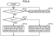
- control operation by the control unit 39a in the variation shown in FIG. 5 will be described with reference to FIG. 6 .
- the operation of the spillback control unit 39b is similar to that in the first embodiment, and the details will be omitted.
- the suction channel may include a heat insulating material for suppressing heat input from the outside air. In this aspect, it is possible to more appropriately control the suction temperature by suppressing unintended heat input in the suction channel.
Landscapes
- Engineering & Computer Science (AREA)
- Mechanical Engineering (AREA)
- General Engineering & Computer Science (AREA)
- Computer Hardware Design (AREA)
- Compressor (AREA)
- Filling Or Discharging Of Gas Storage Vessels (AREA)
- Output Control And Ontrol Of Special Type Engine (AREA)
Abstract
Description
- The present invention relates to a compressor unit.
- Conventionally, low-temperature boil-off gas (BOG) such as liquefied natural gas (LNG) and liquid hydrogen (LH2) is recovered by a compressor and supplied to demand destinations such as engines. In particular, the boil-off gas generated from LH2 has a very low temperature. Therefore, if a configuration is adopted in which the compressor directly suctions in the boil-off gas, restrictions will be imposed, such as it is necessary to select materials suitable for extremely low temperatures, adopt design conditions that take into account the amount of thermal deformation, and implement strict heat insulation treatment.
- In that connection, the following problem has been pointed out in
Patent Literature 1 below. "In recent years, hydrogen has been attracting attention as a new energy source. When hydrogen is used as an energy source, it is assumed that hydrogen will be stored and transported in a liquefied state, like natural gas. However, hydrogen has the property that the liquefaction temperature is lower than the liquefaction temperature of air. Therefore, if facilities such as reciprocating compressors for natural gas and other gases are applied to hydrogen as is, there is a possibility of a trouble caused by cryogenic liquid hydrogen. For example, this may generate liquefied air around the apparatus that is supplied with liquid hydrogen." - That is, in
Patent Literature 1, the problem of preventing troubles caused by cryogenic liquid hydrogen is studied. In an apparatus supplied with a cryogenic fluid, pipes that are easy to install high-performance heat insulation (for example, those with a vacuum area) may be employed. However, there is also a problem that high-performance insulation can be very difficult to install in some apparatuses, such as a machine that vibrates during operation and equipment that requires regular maintenance through inspection openings (such as reciprocating compressors, for example). - As disclosed in Patent Literatures 2 to 4 below, it is known to provide a heat exchanger capable of heating a boil-off gas before being suctioned into a compressor. Meanwhile, if the suctioned gas is heated excessively, the expansion of the gas volume increases the compression power and results in a loss of power (energy). Therefore, it is required to control the suction temperature within an appropriate range.
- In the compressor unit disclosed in Patent Literature 2 below, as shown in
FIG. 12 , aheat exchanger 104 is provided that heats a boil-off gas before being suctioned into acompressor part 102 with the boil-off gas discharged from thecompressor part 102. This compressor unit can change the flow rate that flows through theheat exchanger 104 depending on the gas processing volume. However, due to the configuration in which the entire amount of the boil-off gas derived from atank 100 flows into theheat exchanger 104, the flow rate can only be changed in theheat exchanger 104 depending on the gas processing volume in thecompressor part 102. Therefore, it is not possible to adjust the flow rate flowing through theheat exchanger 104 such that the gas temperature suctioned into thecompressor part 102 becomes a predetermined temperature. - In contrast, the compressor unit disclosed in Patent Literature 3 below is provided with a
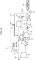
bypass pipe 114 that bypasses theheat exchanger 112, as shown inFIG. 13 . By controlling the opening of avalve 114a provided in thisbypass pipe 114, it is possible to adjust the amount of gas passing through theheat exchanger 112. Therefore, by controlling the opening of thevalve 114a, it may be possible to adjust the temperature of the boil-off gas suctioned into thecompressor part 116. However, in the compressor unit of Patent Literature 3, even if thevalve 114a is fully open, the boil-off gas may flow into theheat exchanger 112 due to pressure loss in thevalve 114a itself. Therefore, it is difficult to control the gas temperature suctioned into thecompressor part 116 so as to fall within an appropriate range. - Note that Patent Literature 4 below also shows, as shown in
FIG. 14 , aheat exchanger 123 that exchanges heat between the boil-off gas before being suctioned into thecompressor part 121 and the boil-off gas after being discharged from thecompressor part 121. However, thisheat exchanger 123 is for re-liquefying the boil-off gas after being compressed in thecompressor part 121. Therefore, the boil-off gas cooled by a cooler 125 disposed downstream of thecompressor part 121 is introduced into theheat exchanger 123. Therefore, Patent Literature 4 is disadvantageous in terms of sufficiently heating the evaporated gas suctioned into thecompressor part 121. Moreover, in Patent Literature 4, as in Patent Literature 3, since the temperature of the gas suctioned into thecompressor part 121 is unlikely to become too high, there is no consideration to adjusting the temperature of the boil-off gas suctioned into thecompressor part 121. -
- Patent Literature 1:
JP 2020-172870 A - Patent Literature 2:
JP 2001-65795 A - Patent Literature 3:
JP H03-92700 A - Patent Literature 4:
JP 2019-27590 A - An object of the present invention is to properly manage the temperature of the hydrogen gas that is a boil-off gas suctioned into a reciprocating compressor part in a compressor unit.
- A compressor unit according to one aspect of the present invention is a compressor unit for recovering a hydrogen gas that is a boil-off gas from a liquid hydrogen storage tank, and supplying at least part of the hydrogen gas to a demand destination including at least one of an engine, a power generation facility, or a boiler. The compressor unit includes: a compressor part including a reciprocating compressor mechanism configured to compress the hydrogen gas flowing through a suction channel and discharges the compressed hydrogen gas into a discharge channel; a water-cooled or air-cooled cooler for cooling the hydrogen gas discharged into the discharge channel; a preheater configured to exchange heat between the hydrogen gas before being suctioned into the compressor part, and the hydrogen gas after being discharged from the compressor part and flowing toward the cooler; and a spillback unit including a spillback channel for returning the hydrogen gas discharged from the compressor part to a part downstream or upstream of the preheater in the suction channel. The discharge channel or the suction channel includes a first routing section and a second routing section that split into two branches along a flow direction of the hydrogen gas and then merge with each other. The first routing section passes through the preheater while the second routing section does not pass through the preheater. The compressor unit further includes: adjustment means configured to adjust a flow rate of the hydrogen gas flowing through the first routing section and adjust a flow rate of the hydrogen gas flowing through the second routing section; and a control unit configured to control the adjustment means such that a suction temperature that is a temperature of the hydrogen gas suctioned into the compressor part falls within a predetermined temperature range. The predetermined temperature range is higher than a reference temperature based on a liquefaction temperature of air.
-
-
FIG. 1 is a diagram schematically showing a configuration of a compressor unit according to a first embodiment. -
FIG. 2 is a diagram schematically showing the configuration of the compressor unit according to the first embodiment. -
FIG. 3 is a diagram schematically showing the configuration of the compressor unit according to a variation of the first embodiment. -
FIG. 4 is a diagram for describing a control operation of a control unit in the compressor unit according to the first embodiment. -
FIG. 5 is a diagram schematically showing the configuration of the compressor unit according to the variation of the first embodiment. -
FIG. 6 is a diagram for describing the control operation of the control unit in the compressor unit according to the variation of the first embodiment. -
FIG. 7 is a diagram schematically showing the configuration of the compressor unit according to the variation of the first embodiment. -
FIG. 8 is a diagram schematically showing a configuration of a compressor unit according to a second embodiment. -
FIG. 9 is a diagram schematically showing a configuration of a compressor unit according to a third embodiment. -
FIG. 10 is a diagram schematically showing a configuration of a compressor unit according to a fourth embodiment. -
FIG. 11 is a diagram schematically showing a configuration of a compressor unit according to a fifth embodiment. -
FIG. 12 is a diagram schematically showing a conventional compressor unit. -
FIG. 13 is a diagram schematically showing the conventional compressor unit. -
FIG. 14 is a diagram schematically showing the conventional compressor unit. - Embodiments will be described below with reference to the accompanying drawings.
- A compressor unit according to the present embodiment is configured to recover a hydrogen gas, which is a flammable boil-off gas below 0°C, from a liquid hydrogen storage tank, compress the recovered hydrogen gas, and supply the hydrogen gas to a demand destination. The boil-off gas, which is a hydrogen gas, is at about -250°C. Examples of the demand destination include power generation equipment, boilers, and engines for ships or the like.
- As shown in
FIG. 1 , thecompressor unit 10 includes acompressor part 12 for compressing the hydrogen gas, a cooler 14 for cooling the hydrogen gas compressed by thecompressor part 12, and apreheater 16 for heating the hydrogen gas before being suctioned into thecompressor part 12. - The
compressor part 12 is connected to a liquidhydrogen storage tank 23 via asuction channel 21. Therefore, the boil-off gas that is a liquefied gas generated inside the liquidhydrogen storage tank 23 is suctioned into thecompressor part 12 through thesuction channel 21. Thecompressor part 12 is configured by a reciprocating compressor mechanism. That is, as shown inFIG. 2 , thecompressor part 12 includes acylinder part 211, apiston 212, apiston rod 213, a pair ofsuction valves 214, and a pair ofdischarge valves 215. Thepiston 212 and thepiston rod 213 are connected to a crank mechanism (not shown). By thepiston 212 reciprocating inside thecylinder part 211, the hydrogen gas is compressed inside a compression chamber.FIG. 2 shows thecompressor part 12 having a double acting structure, but thecompressor part 12 may also have a single acting structure. - Note that for convenience,
FIG. 1 shows thecompressor part 12 as a single trapezoid, but thecompressor part 12 does not necessarily have to be a single stage compressor, but may include multiple compression stages. That is, thecompressor part 12 may be configured such that the hydrogen gas is sequentially compressed and pressurized by thepistons 212 insidemultiple cylinder parts 211 connected in series. The same applies to other embodiments described later. - The
suction channel 21 includes aheat insulating material 26 for suppressing heat input from the outside air. Note that theheat insulating material 26 may be omitted. In addition, a heat insulating material (not shown) may also be provided in adischarge channel 25 through which the hydrogen gas discharged from thecompressor part 12 flows. - The cooler 14 is disposed on the
discharge channel 25. The cooler 14 may be of a water-cooled type or an air-cooled type. The hydrogen gas cooled by the cooler 14 is sent to ademand destination 28. - The
preheater 16 is configured to exchange heat between the hydrogen gas before being suctioned into thecompressor part 12 and the hydrogen gas after being discharged from thecompressor part 12, and to heat the hydrogen gas before being suctioned into thecompressor part 12. Thepreheater 16 is connected to thedischarge channel 25 upstream of the cooler 14. In thepreheater 16, the hydrogen gas flowing through thesuction channel 21 toward thecompressor part 12 is heated by the hydrogen gas flowing toward the cooler 14. Therefore, unlike a configuration in which heating is performed using the hydrogen gas after being cooled by the cooler 14, the hydrogen gas can be heated effectively. - The
preheater 16 is connected to afirst routing section 29a of thedischarge channel 25. That is, thedischarge channel 25 includes anupstream routing section 29b, thefirst routing section 29a and asecond routing section 29c that split into two branches from theupstream routing section 29b and then merge with each other, and adownstream routing section 29d through which the hydrogen gas merged from thefirst routing section 29a and thesecond routing section 29c flows. Theupstream routing section 29b is connected to thecompressor part 12. Thedownstream routing section 29d extends to thedemand destination 28. - Since the
first routing section 29a passes through thepreheater 16, at least part of the hydrogen gas discharged from thecompressor part 12 can flow into thepreheater 16. Since thepreheater 16 is also connected to thesuction channel 21, the hydrogen gas flowing through thesuction channel 21 can be heated by the hydrogen gas flowing through thefirst routing section 29a. Meanwhile, thesecond routing section 29c does not pass through thepreheater 16. - The
downstream routing section 29d is connected to the cooler 14. That is, in thedischarge channel 25, the cooler 14 is disposed downstream of thepreheater 16. Therefore, thepreheater 16 heats the hydrogen gas flowing through thesuction channel 21 by using the hydrogen gas before being cooled by the cooler 14. - The
discharge channel 25 is provided with adjustment means 31 that adjusts the flow rate of the hydrogen gas flowing through thefirst routing section 29a and adjusts the flow rate of the hydrogen gas flowing through thesecond routing section 29c. In the example shown inFIG. 1 , the adjustment means 31 includes a three-way valve 31a provided at the branch point of thefirst routing section 29a and thesecond routing section 29c. The three-way valve 31a is configured to distribute the hydrogen gas flowing through theupstream routing section 29b to thefirst routing section 29a and thesecond routing section 29c. Therefore, by changing the orientation or position of a valve body (not shown) of the three-way valve 31a, the three-way valve 31a is configured to be able to change the distribution ratio to thefirst routing section 29a and thesecond routing section 29c from a state in which the entire flow rate flowing through theupstream routing section 29b flows through thefirst routing section 29a (second routing section 29c side is closed) to a state in which the entire flow rate flowing through theupstream routing section 29b flows through thesecond routing section 29c (first routing section 29a side andpreheater 16 side are closed). - Note that in the configuration of
FIG. 1 , the three-way valve 31a is disposed in the place where theupstream routing section 29b, thefirst routing section 29a, and thesecond routing section 29c are connected to each other, but alternatively, the three-way valve 31a may be disposed in the place where thefirst routing section 29a, thesecond routing section 29c, and thedownstream routing section 29d are connected to each other. - The
compressor unit 10 is provided with aspillback unit 33 for returning the hydrogen gas discharged from thecompressor part 12 to thesuction channel 21. Thespillback unit 33 includes aspillback channel 33a and aspillback valve 33b including a valve disposed in thespillback channel 33a and having an adjustable opening. One end of thespillback channel 33a is connected to a part downstream of the cooler 14 in thedischarge channel 25, whereas the other end is connected to a part downstream of thepreheater 16 in thesuction channel 21. That is, the hydrogen gas flowing through thespillback channel 33a merges with the hydrogen gas that passes through thepreheater 16 between thepreheater 16 and thecompressor part 12 in thesuction channel 21. The downstream part of thespillback valve 33b in thespillback channel 33a is provided with aheat insulating material 34 for suppressing heat input from the outside air. However, theheat insulating material 34 can be omitted. Note that as shown inFIG. 3 , the other end of thespillback channel 33a may be connected to a part upstream of thepreheater 16 in thesuction channel 21. - The
discharge channel 25 is provided with apressure sensor 36 for detecting the pressure of the hydrogen gas flowing through thedischarge channel 25. Thepressure sensor 36 is located downstream of the connection part where thespillback channel 33a connects to thedischarge channel 25. - The
suction channel 21 is provided with atemperature sensor 37 for detecting the temperature of the hydrogen gas flowing through thesuction channel 21. Thetemperature sensor 37 is disposed between thecompressor part 12 and the connection part where thespillback channel 33a is connected in thesuction channel 21. Therefore, thetemperature sensor 37 can acquire the temperature of the hydrogen gas after being heated by the preheater 16 (hydrogen gas after the hydrogen gas from thespillback channel 33a merges if the hydrogen gas flows through thespillback channel 33a). - The
pressure sensor 36 outputs a signal indicative of the detected pressure, whereas thetemperature sensor 37 outputs a signal indicative of the acquired temperature. The signal from thepressure sensor 36 and the signal from thetemperature sensor 37 are input into acontroller 39. Thecontroller 39 is a computer that controls various operations of thecompressor unit 10. Functions of thecontroller 39 executed by this computer include acontrol unit 39a and aspillback control unit 39b. Thecontrol unit 39a is a functional unit configured to control the adjustment means 31 while referring to the temperature acquired by thetemperature sensor 37 as a suction temperature, which is the temperature of the hydrogen gas suctioned into thecompressor part 12. Thespillback control unit 39b is a functional unit configured to control thespillback valve 33b based on the detected pressure of thepressure sensor 36. - Here, the control operation by the
control unit 39a will be described with reference toFIG. 4 . Thecontrol unit 39a first determines whether the suction temperature (temperature T) is equal to or lower than a predetermined target temperature T1 (step ST13). Note that the target temperature T1 is set to a temperature higher than a reference temperature described later. - When the suction temperature (temperature T) is equal to or lower than the target temperature T1, the
control unit 39a controls the adjustment means 31 to decrease the flow rate bypassing thepreheater 16 and increase the flow rate flowing through the preheater 16 (step ST14). That is, the three-way valve 31a as the adjustment means 31 is controlled such that the opening on thesecond routing section 29c side decreases and the opening on thefirst routing section 29a side increases. This causes the amount of heat applied to the hydrogen gas flowing through thesuction channel 21 to increase in thepreheater 16, thereby increasing the suction temperature (temperature T). - On the other hand, when the suction temperature (temperature T) is higher than the target temperature T1, the
control unit 39a controls the adjustment means 31 to increase the flow rate bypassing thepreheater 16 and decrease the flow rate flowing through the preheater 16 (step ST15). That is, the three-way valve 31a as the adjustment means 31 is controlled such that the opening on thesecond routing section 29c side increases and the opening on thefirst routing section 29a side decreases. This causes the amount of heat applied to the hydrogen gas flowing through thesuction channel 21 to decrease in thepreheater 16, thereby decreasing the suction temperature (temperature T). That is, thecontrol unit 39a controls the adjustment means 31 such that the suction temperature falls within a predetermined temperature range. The temperature range is higher than the predetermined reference temperature. - The reference temperature is set based on the liquefaction temperature of air. Specifically, the reference temperature is preferably the liquefaction temperature of air. However, if the outer surface of a member that comes into contact with the outside air in the compressor part 12 (such as cylinder part 211) becomes higher than the liquefaction temperature of air, the reference temperature can also be lower than the liquefaction temperature of air. The reference temperature may be set such that the temperature of outer surfaces of the piping and instrumentation of the
suction channel 21 is higher than the liquefaction temperature of air. This prevents the air from liquefying even if the air around thecompressor part 12 and thesuction channel 21 is cooled by the cold heat of the hydrogen gas. - The
spillback control unit 39b controls thespillback valve 33b such that the pressure detected by thepressure sensor 36 becomes a predetermined set pressure. That is, when the pressure detected by thepressure sensor 36 is higher than the set pressure, thespillback valve 33b is controlled to increase the opening of thespillback valve 33b. This causes the flow rate of the hydrogen gas returned to thesuction channel 21 to increase, out of the hydrogen gas that has passed through the cooler 14, thereby decreasing the pressure of the hydrogen gas supplied to thedemand destination 28. On the other hand, when the pressure detected is lower than the set pressure, thespillback valve 33b is controlled to decrease the opening of thespillback valve 33b. This causes the flow rate of the hydrogen gas returned to thesuction channel 21 to decrease, out of the hydrogen gas that has passed through the cooler 14, thereby increasing the pressure of the hydrogen gas supplied to thedemand destination 28. When the detected pressure agrees with the set pressure, the opening of thespillback valve 33b is not changed. - As described above, in the present embodiment, by using the adjustment means 31, the flow rate of the hydrogen gas that passes through the
preheater 16 is adjusted, and the flow rate of the hydrogen gas that does not pass through thepreheater 16 is also adjusted. Furthermore, the adjustment means 31 is controlled such that the temperature of the hydrogen gas suctioned into thecompressor part 12 falls within the predetermined temperature range. Therefore, the suction temperature of thecompressor part 12 can be appropriately managed. In addition, by using the heat of the hydrogen gas before flowing into the cooler 14 (discharge gas), the suction temperature can be appropriately heated. Furthermore, since the connection part where thespillback channel 33a is connected to thesuction channel 21 is located upstream of thetemperature sensor 37, even if the gas temperature detected by thetemperature sensor 37 changes due to the hydrogen gas returned to thesuction channel 21 by thespillback unit 33, the temperature of the hydrogen gas suctioned into thecompressor part 12 can be kept within an appropriate range. Moreover, since the temperature of the hydrogen gas suctioned into thecompressor part 12 can be made higher than the above-mentioned reference temperature, liquefaction of oxygen, which is a combustion supporting gas, can be avoided. - In the present embodiment, the adjustment means 31 includes the three-
way valve 31a. Therefore, one valve can adjust the flow rate of the hydrogen gas toward thepreheater 16 and also adjust the flow rate of the hydrogen gas that does not pass through thepreheater 16, contributing to simplifying the configuration. - In the present embodiment, since the
suction channel 21 includes theheat insulating material 26, unintended heat input in thesuction channel 21 can be suppressed, thereby allowing the suction temperature to be controlled more appropriately. -
FIG. 1 shows an example in which the adjustment means 31 includes the three-way valve 31a, but the present embodiment is not limited to this example. As shown inFIG. 5 , the adjustment means 31 may include afirst valve 31b provided on thefirst routing section 29a and having an adjustable opening, and asecond valve 31c provided on thesecond routing section 29c and having an adjustable opening. - Here, the control operation by the
control unit 39a in the variation shown inFIG. 5 will be described with reference toFIG. 6 . Note that the operation of thespillback control unit 39b is similar to that in the first embodiment, and the details will be omitted. - The
control unit 39a determines whether the suction temperature (temperature T) acquired by thetemperature sensor 37 is equal to or higher than a predetermined upper limit temperature T2 (step ST11). When the suction temperature (temperature T) is equal to or higher than the upper limit temperature T2, thecontrol unit 39a controls the adjustment means 31 to stop the flow of the hydrogen gas through thefirst routing section 29a (step ST12). In this case, thefirst valve 31b is closed and thesecond valve 31c is fully opened. This stops the flow of the hydrogen gas discharged from thecompressor part 12 into thepreheater 16. Therefore, the hydrogen gas flowing through thesuction channel 21 is suctioned into thecompressor part 12 without being heated in thepreheater 16. Therefore, the temperature of the hydrogen gas suctioned into the compressor part 12 (suction temperature) can be prevented from becoming excessively high. - On the other hand, when the suction temperature (temperature T) is lower than the upper limit temperature T2, as in
FIG. 4 , thecontrol unit 39a determines whether the suction temperature (temperature T) is equal to or lower than the predetermined target temperature T1 (step ST13). At this time, since the adjustment means 31 is open to at least thefirst routing section 29a side, at least part of the hydrogen gas discharged from thecompressor part 12 is introduced into thepreheater 16. Note that the target temperature T1 is a temperature lower than the upper limit temperature T2. - When the suction temperature (temperature T) is equal to or lower than the target temperature T1, the
control unit 39a controls the adjustment means 31 to decrease the flow rate bypassing thepreheater 16 and increase the flow rate flowing through the preheater 16 (step ST14). That is, thesecond valve 31c is controlled such that the opening of thesecond valve 31c decreases, and thefirst valve 31b is controlled such that the opening of thefirst valve 31b increases. As a result, the gas flow rate passing through thepreheater 16 out of the discharge gas increases, whereas the gas flow rate bypassing thepreheater 16 decreases. - On the other hand, when the suction temperature (temperature T) is higher than the target temperature T1, the
control unit 39a controls the adjustment means 31 to increase the flow rate bypassing thepreheater 16 and decrease the flow rate flowing through the preheater 16 (step ST15). That is, thesecond valve 31c is controlled such that the opening of thesecond valve 31c increases, and thefirst valve 31b is controlled such that the opening of thefirst valve 31b decreases. As a result, the gas flow rate passing through thepreheater 16 out of the discharge gas decreases, whereas the gas flow rate bypassing thepreheater 16 increases. That is, the flow of the hydrogen gas discharged from thecompressor part 12 into thepreheater 16 is adjusted such that the suction temperature is within the predetermined temperature range. - Note that in the configuration shown in
FIG. 5 , the control operation by thecontrol unit 39a may be performed based onFIG. 4 (that is, inFIG. 6 , steps ST11 and ST12 may be omitted). In the configuration ofFIG. 1 , the above-mentioned steps ST11 and ST12 may be performed. - As shown in
FIG. 7 , the adjustment means 31 may include avalve 31d provided on thefirst routing section 29a and having an adjustable opening, and athrottle part 31e provided on thesecond routing section 29c. Thethrottle part 31e suppresses the flow rate of the hydrogen gas flowing through thesecond routing section 29c. Therefore, when thevalve 31d is fully opened, almost the entire amount of hydrogen gas discharged from thecompressor part 12 flows through thefirst routing section 29a. On the other hand, when thevalve 31d is closed, the entire amount of hydrogen gas discharged from thecompressor part 12 flows through thesecond routing section 29c. - In this configuration, the
control unit 39a performs the same control operation as inFIG. 6 . In step ST12 ofFIG. 6 , thevalve 31d of thefirst routing section 29a is closed. This stops the flow of the hydrogen gas discharged from thecompressor part 12 into thepreheater 16. In step ST14, thevalve 31d is controlled such that the opening of thevalve 31d increases. As a result, the gas flow rate passing through thepreheater 16 increases, and the gas flow rate passing through thethrottle part 31e decreases. In step ST15, thevalve 31d is controlled such that the opening of thevalve 31d decreases. As a result, the gas flow rate passing through thepreheater 16 decreases, and the gas flow rate passing through thethrottle part 31e increases. That is, the flow of the hydrogen gas discharged from thecompressor part 12 into thepreheater 16 is adjusted such that the suction temperature is within the predetermined temperature range. Note that in the configuration shown inFIG. 7 , thecontrol unit 39a may perform the same control operation as inFIG. 4 . -
FIG. 8 shows a second embodiment of the present invention. Here, the same components as those of the first embodiment are denoted with the same reference numerals, and detailed descriptions thereof will be omitted. - In the first embodiment, the
discharge channel 25 includes thefirst routing section 29a and thesecond routing section 29c. In contrast, in the second embodiment, asuction channel 21 includes afirst routing section 29a and asecond routing section 29c. That is, thesuction channel 21 includes anupstream routing section 29b, thefirst routing section 29a and thesecond routing section 29c that split into two branches from theupstream routing section 29b and then merge with each other, and adownstream routing section 29d through which the hydrogen gas merged from thefirst routing section 29a and thesecond routing section 29c flows. - The
upstream routing section 29b is connected to a liquidhydrogen storage tank 23. Thedownstream routing section 29d is connected to acompressor part 12. Thefirst routing section 29a passes through apreheater 16, whereas thesecond routing section 29c bypasses thepreheater 16. - One end of a
spillback channel 33a is connected to a part downstream of a cooler 14 in adischarge channel 25, whereas the other end is connected to a part downstream of thepreheater 16 in thesuction channel 21. That is, the other end of thespillback channel 33a is connected to thedownstream routing section 29d of thesuction channel 21. - Adjustment means 31 includes a
first valve 31b provided on thefirst routing section 29a and having an adjustable opening, and asecond valve 31c provided on thesecond routing section 29c and having an adjustable opening. In this case, in step ST12 ofFIG. 6 when a suction temperature (temperature T) is equal to or higher than an upper limit temperature T2, thefirst valve 31b is closed and thesecond valve 31c is fully opened. This prevents the hydrogen gas heading from the liquidhydrogen storage tank 23 to thecompressor part 12 from flowing into thepreheater 16. Therefore, the hydrogen gas is not heated in thepreheater 16 before flowing into thecompressor part 12. - In step ST14 of
FIG. 6 when the suction temperature (temperature T) is equal to or lower than a target temperature T1, thesecond valve 31c is controlled to decrease the opening of thesecond valve 31c, and thefirst valve 31b is controlled to increase the opening of thefirst valve 31b. As a result, the gas flow rate passing through thepreheater 16 increases, whereas the gas flow rate bypassing thepreheater 16 decreases. In step ST15 when the suction temperature (temperature T) is higher than the target temperature T1, thesecond valve 31c is controlled to increase the opening of thesecond valve 31c, and thefirst valve 31b is controlled to decrease the opening of thefirst valve 31b. As a result, the gas flow rate passing through thepreheater 16 decreases, whereas the gas flow rate bypassing thepreheater 16 increases. That is, the flow rate of the hydrogen gas flowing into thepreheater 16 is adjusted such that the suction temperature is within the predetermined temperature range. - Note that
FIG. 8 shows an example in which the adjustment means 31 includes thefirst valve 31b and thesecond valve 31c, but the adjustment means 31 may include a three-way valve provided at the branch point of thefirst routing section 29a and thesecond routing section 29c. The adjustment means 31 may include a valve disposed in thefirst routing section 29a and a throttle part disposed in thesecond routing section 29c. - Although other configurations, operations, and effects are not described, the description of the first embodiment can be applied to the second embodiment.
-
FIG. 9 shows a third embodiment of the present invention. Here, the same components as those of the first and second embodiments are denoted with the same reference numerals, and detailed descriptions thereof will be omitted. - The third embodiment further includes a
second compressor part 42 that compresses the hydrogen gas after being cooled by the cooler 14, and asecond cooler 44 that cools the hydrogen gas compressed by thesecond compressor part 42. - The cooler 14, the
second compressor part 42, and thesecond cooler 44 are provided on thedischarge channel 25. Thesecond compressor part 42 is configured using a reciprocating compressor mechanism. That is, thesecond compressor part 42 includes a cylinder part, a piston, a piston rod, a pair of suction valves, and a pair of discharge valves, in a similar manner to acompressor part 12. Note that for convenience,FIG. 9 shows thesecond compressor part 42 as a single trapezoid, but thesecond compressor part 42 does not necessarily have to be a single stage compressor, but may include multiple compression stages. - The
second compressor part 42 is driven by a crank mechanism common to thecompressor part 12. In other words, thesecond compressor part 42 together with thecompressor part 12 constitutes a single multi-stage reciprocating compressor. Note that thesecond compressor part 42 may be configured as a reciprocating compressor independent of thecompressor part 12. - The cooler 14 functions as an intercooler that cools the hydrogen gas suctioned into the
second compressor part 42, and the second cooler 44 functions as an aftercooler that cools the hydrogen gas discharged from thesecond compressor part 42. Thesecond cooler 44 may be of a water-cooled type or an air-cooled type, in a similar manner to the cooler 14. The hydrogen gas cooled by thesecond cooler 44 is sent to ademand destination 28. - A
spillback unit 33 includes afirst spillback unit 45 and asecond spillback unit 46. Note that thespillback unit 33 may include only thesecond spillback unit 46. That is, thefirst spillback unit 45, which is an interstage spillback unit, can be omitted. - The
first spillback unit 45 includes afirst spillback channel 45a and afirst spillback valve 45b including a valve disposed on thefirst spillback channel 45a and having an adjustable opening. One end of thefirst spillback channel 45a is connected to a part between the cooler 14 and thesecond compressor part 42 in thedischarge channel 25, whereas the other end is connected to a part downstream of apreheater 16 in asuction channel 21. The portion downstream of thefirst spillback valve 45b in thefirst spillback channel 45a is provided with aheat insulating material 48 for suppressing heat input from the outside air. However, theheat insulating material 48 can be omitted. Note that the other end of thefirst spillback channel 45a may be connected to a part upstream of thepreheater 16 in thesuction channel 21. - The
second spillback unit 46 includes asecond spillback channel 46a and asecond spillback valve 46b including a valve disposed on thesecond spillback channel 46a and having an adjustable opening. One end of thesecond spillback channel 46a is connected to a part downstream of thesecond cooler 44 in thedischarge channel 25, whereas the other end is connected to a part downstream of thepreheater 16 in thesuction channel 21. The portion downstream of thesecond spillback valve 46b in thesecond spillback channel 46a is provided with aheat insulating material 49 for suppressing heat input from the outside air. However, theheat insulating material 49 can be omitted. Note that the other end of thesecond spillback channel 46a may be connected to a part upstream of thepreheater 16 in thesuction channel 21. - The
discharge channel 25 is provided with asecond pressure sensor 51 for detecting the pressure of the hydrogen gas flowing through thesecond cooler 44. Thesecond pressure sensor 51 is located downstream of the connection part of thesecond spillback channel 46a in thedischarge channel 25. - A
spillback control unit 39b controls thefirst spillback valve 45b based on the pressure detected by thepressure sensor 36, and controls thesecond spillback valve 46b based on the pressure detected by thesecond pressure sensor 51. - Note that
FIG. 9 shows an example in which adjustment means 31 includes a three-way valve 31a. However, as in the case shown inFIG. 5 , the adjustment means 31 may include a first valve provided on thefirst routing section 29a and having an adjustable opening, and a second valve provided on thesecond routing section 29c and having an adjustable opening. As in the case shown inFIG. 7 , the adjustment means 31 may include a valve provided on thefirst routing section 29a and having an adjustable opening, and a throttle part provided on thesecond routing section 29c. -
FIG. 9 shows an example in which thedischarge channel 25 includes thefirst routing section 29a and thesecond routing section 29c, but alternatively, similar to the case shown inFIG. 8 , thesuction channel 21 may include thefirst routing section 29a and thesecond routing section 29c. - Although other configurations, operations, and effects are not described, the description of the first and second embodiments can be applied to the third embodiment.
-
FIG. 10 shows a fourth embodiment of the present invention. Here, the same components as those of the first and second embodiments are denoted with the same reference numerals, and detailed descriptions thereof will be omitted. - The fourth embodiment further includes a
prestage compressor part 55 that compresses the hydrogen gas before being compressed by thecompressor part 12, an interstage cooler 57 that cools the hydrogen gas compressed by theprestage compressor part 55, and aninterstage spillback unit 59. - The
prestage compressor part 55 and theinterstage cooler 57 are provided on thesuction channel 21. Theprestage compressor part 55 is configured using a reciprocating compressor mechanism. That is, theprestage compressor part 55 includes a cylinder part, a piston, a piston rod, a pair of suction valves, and a pair of discharge valves, in a similar manner to thecompressor part 12. Note that for convenience,FIG. 10 shows theprestage compressor part 55 as a single trapezoid, but theprestage compressor part 55 does not necessarily have to be a single stage compressor, but may include multiple compression stages. - The
prestage compressor part 55 is driven by a crank mechanism common to thecompressor part 12. In other words, theprestage compressor part 55 together with thecompressor part 12 constitutes a single multi-stage reciprocating compressor. Note that theprestage compressor part 55 may be configured as a reciprocating compressor independent of thecompressor part 12. - In the part of the
suction channel 21 from the liquidhydrogen storage tank 23 to theprestage compressor part 55, aheat insulating material 26 is provided to suppress heat input from the outside air. - The interstage cooler 57 functions as an intercooler that cools the hydrogen gas before being suctioned into the
compressor part 12, and the cooler 14 functions as an aftercooler that cools the hydrogen gas discharged from thecompressor part 12. Theinterstage cooler 57 may be of a water-cooled type or an air-cooled type, in a similar manner to the cooler 14. The hydrogen gas cooled by the cooler 14 is sent to ademand destination 28. - The
interstage spillback unit 59 includes aninterstage spillback channel 59a and aninterstage spillback valve 59b including a valve disposed on theinterstage spillback channel 59a and having an adjustable opening. One end of theinterstage spillback channel 59a is connected to a part between theinterstage cooler 57 and thecompressor part 12 in thesuction channel 21, whereas the other end is connected to a part between thepreheater 16 and theprestage compressor part 55 in thesuction channel 21. The portion downstream of theinterstage spillback valve 59b in theinterstage spillback channel 59a is provided with aheat insulating material 48 for suppressing heat input from the outside air. - The
suction channel 21 is provided with aninterstage pressure sensor 61 for detecting the pressure of the hydrogen gas that has passed through theinterstage cooler 57. Theinterstage pressure sensor 61 is located downstream of the connection part of theinterstage spillback channel 59a in thesuction channel 21. Therefore, theinterstage pressure sensor 61 can detect the pressure of the hydrogen gas suctioned into thecompressor part 12. - A
spillback control unit 39b controls theinterstage spillback valve 59b based on the pressure detected by theinterstage pressure sensor 61, and controls aspillback valve 33b based on the pressure detected by thepressure sensor 36. - Although other configurations, operations, and effects are not described, the description of the first to third embodiments can be applied to the fourth embodiment.
-
FIG. 11 shows a fifth embodiment of the present invention. Here, the same components as those of the first to fourth embodiments are denoted with the same reference numerals, and detailed descriptions thereof will be omitted. - In the first embodiment, the
temperature sensor 37 is located on thesuction channel 21 and detects the suction temperature directly. In contrast, the fifth embodiment is configured such that atemperature sensor 37 is located on thedischarge channel 25 and detects the discharge temperature. Thetemperature sensor 37 is disposed on theupstream routing section 29b of thedischarge channel 25. That is, thetemperature sensor 37 is disposed between thepreheater 16 and thecompressor part 12 in thedischarge channel 25. - Functions of a
controller 39 include acalculation unit 39c that estimates the suction side temperature of thecompressor part 12 based on the discharge temperature acquired by thetemperature sensor 37. Thecalculation unit 39c is configured to derive the suction side temperature from the discharge temperature by using the relational expression, map, and the like stored in thecontroller 39 and associating the discharge temperature with the suction side temperature. The relational expression is, for example, a relational expression assuming that the hydrogen gas is adiabatically compressed in thecompressor part 12, and may be a relational expression that defines the relationship between the suction pressure, the suction side temperature, the discharge pressure, and the discharge temperature. The map is a map of data obtained through preliminary testing and may be a map configured to associate the suction temperature with the discharge temperature. Thecontrol unit 39a controls adjustment means 31 while referring to the suction side temperature estimated by thecalculation unit 39c as the suction temperature, which is the temperature of the hydrogen gas suctioned into thecompressor part 12. - In the flow shown in
FIG. 4 , before step ST13 is executed, the suction temperature is estimated by thecalculation unit 39c based on the discharge temperature. In step ST13, the suction temperature (temperature T) estimated by thecalculation unit 39c is used. The control flow other than this is the same as the flow inFIG. 4 . - Therefore, in the present embodiment, the adjustment means 31 adjusts the flow rate of the hydrogen gas passing through the
preheater 16, and also adjusts the flow rate of the hydrogen gas that does not pass through thepreheater 16. Furthermore, the adjustment means 31 is controlled such that the temperature of the hydrogen gas suctioned into thecompressor part 12 falls within the predetermined temperature range. Therefore, the suction temperature of thecompressor part 12 can be appropriately managed. In addition, by using the heat of the hydrogen gas before flowing into the cooler 14 (discharge gas), the suction temperature can be appropriately heated. - Note that
FIG. 11 shows an example in which the adjustment means 31 includes a three-way valve 31a. However, as in the case shown inFIG. 5 , the adjustment means 31 may include afirst valve 31b provided on thefirst routing section 29a and having an adjustable opening, and asecond valve 31c provided on thesecond routing section 29c and having an adjustable opening. As in the case shown inFIG. 7 , the adjustment means 31 may include avalve 31d provided on thefirst routing section 29a and having an adjustable opening, and athrottle part 31e provided on thesecond routing section 29c. -
FIG. 11 shows an example in which thedischarge channel 25 includes thefirst routing section 29a and thesecond routing section 29c, but alternatively, as in the case shown inFIG. 8 , thesuction channel 21 may include thefirst routing section 29a and thesecond routing section 29c. In addition, a second compressor part and a second cooler may be further provided, as in the case shown inFIG. 9 . In this case, aspillback unit 33 may include a first spillback unit and a second spillback unit. As in the configuration shown inFIG. 10 , the configuration including aprestage compressor part 55, aninterstage cooler 57, and aninterstage spillback unit 59 may be used. In addition, in the configuration ofFIG. 11 , the control operation shown inFIG. 6 may be performed. - Although other configurations, operations, and effects are not described, the description of the first to fourth embodiments can be applied to the fifth embodiment.
- It should be understood that the embodiments disclosed herein are illustrative in all respects and are not restrictive. The scope of the present invention is indicated by the scope of claims instead of the above description, and is intended to include meanings equivalent to the scope of claims and all modifications within the scope.
- In the
compressor unit 10 shown inFIG. 1 , thespillback valve 33b may be controlled based on the detection value of the pressure sensor installed on thesuction channel 21. Thespillback valve 33b may be controlled based on both thepressure sensor 36 and the pressure sensor provided on thesuction channel 21. Furthermore, thespillback valve 33b may be controlled based on the flow rate sensor (disposed where thepressure sensor 36 is disposed) instead of thepressure sensor 36. The same applies to the spillback valve in other embodiments. - Here, the above embodiments will be outlined.
- (1) A compressor unit according to the above embodiments is a compressor unit for recovering a hydrogen gas that is a boil-off gas from a liquid hydrogen storage tank, and supplying at least part of the hydrogen gas to a demand destination including at least one of an engine, a power generation facility, or a boiler. The compressor unit includes: a compressor part including a reciprocating compressor mechanism configured to compress the hydrogen gas flowing through a suction channel and discharge the compressed hydrogen gas into a discharge channel; a water-cooled or air-cooled cooler for cooling the hydrogen gas discharged into the discharge channel; a preheater configured to exchange heat between the hydrogen gas before being suctioned into the compressor part, and the hydrogen gas after being discharged from the compressor part and flowing toward the cooler; and a spillback unit including a spillback channel for returning the hydrogen gas discharged from the compressor part to a part downstream or upstream of the preheater in the suction channel. The discharge channel or the suction channel includes a first routing section and a second routing section that split into two branches along a flow direction of the hydrogen gas and then merge with each other. The first routing section passes through the preheater while the second routing section does not pass through the preheater. The compressor unit further includes: adjustment means configured to adjust a flow rate of the hydrogen gas flowing through the first routing section and adjust a flow rate of the hydrogen gas flowing through the second routing section; and a control unit configured to control the adjustment means such that a suction temperature that is a temperature of the hydrogen gas suctioned into the compressor part falls within a predetermined temperature range. The predetermined temperature range is higher than a reference temperature based on a liquefaction temperature of air.
- In this compressor unit, the adjustment means adjusts the flow rate of the hydrogen gas passing through the preheater and the flow rate of the hydrogen gas that does not pass through the preheater. Furthermore, the adjustment means is controlled such that the temperature of the hydrogen gas suctioned into the compressor part falls within the predetermined temperature range. Therefore, the suction temperature of the compressor part can be appropriately managed. In addition, by using the heat of the hydrogen gas before flowing into the cooler (discharge gas), the suction temperature can be appropriately heated. Moreover, since the temperature range of the hydrogen gas suctioned into the compressor part can be made higher than the predetermined reference temperature, liquefaction of oxygen, which is a combustion supporting gas, can be avoided.
- (2) The compressor unit may further include a temperature sensor disposed between a connection part of the spillback channel and the compressor part in the suction channel. In this case, the control unit may be configured to refer to the temperature acquired by the temperature sensor as the suction temperature. In this aspect, since the connection part where the spillback channel is connected to the suction channel is located upstream of the temperature sensor, even if the gas temperature detected by the temperature sensor changes due to the hydrogen gas returned to the suction channel by the spillback unit, the temperature of the hydrogen gas suctioned into the compressor part can be kept within an appropriate range.
- (3) The compressor unit is configured to recover the hydrogen gas that is a flammable boil-off gas lower than 0°C from the liquid hydrogen storage tank. The compressor unit may further include: a temperature sensor disposed between the preheater and the compressor part in the discharge channel; and a calculation unit configured to estimate a suction side temperature of the compressor part based on a discharge temperature acquired by the temperature sensor. In this case, the control unit may be configured to refer to the suction side temperature estimated by the calculation unit as the suction temperature.
- In this aspect, the adjustment means adjusts the flow rate of the hydrogen gas passing through the preheater and the flow rate of the hydrogen gas that does not pass through the preheater. Furthermore, the adjustment means is controlled such that the temperature of the hydrogen gas suctioned into the compressor part falls within the predetermined temperature range. Therefore, the suction temperature of the compressor part can be appropriately managed. In addition, by using the heat of the hydrogen gas before flowing into the cooler (discharge gas), the suction temperature can be appropriately heated. Moreover, since the temperature range of the hydrogen gas suctioned into the compressor part can be made higher than the predetermined reference temperature, liquefaction of oxygen, which is a combustion supporting gas, can be avoided.
- (4) The adjustment means may include a three-way valve provided at a branch point of the first routing section and the second routing section. In this aspect, one valve can adjust the flow rate of the hydrogen gas toward the preheater and the flow rate of the hydrogen gas that does not pass through the preheater, contributing to simplifying the configuration.
- (5) The adjustment means may include a valve provided on the first routing section and having an adjustable opening, and a valve provided on the second routing section and having an adjustable opening.
- (6) The adjustment means may include a valve provided on the first routing section and having an adjustable opening, and a throttle part provided on the second routing section to suppress the flow rate of the hydrogen gas.
- (7) The control unit may be configured to control the adjustment means to stop flow of the hydrogen gas in the first routing section when the suction temperature is equal to or higher than a predetermined upper limit temperature, and control the adjustment means such that the suction temperature is within the predetermined temperature range when the suction temperature is lower than the upper limit temperature. In this aspect, the flow of the hydrogen gas in the preheater is stopped when the suction temperature is equal to or higher than the predetermined upper limit temperature, preventing the temperature of the hydrogen gas suctioned into the compressor part from becoming too high.
- (8) The suction channel may include a heat insulating material for suppressing heat input from the outside air. In this aspect, it is possible to more appropriately control the suction temperature by suppressing unintended heat input in the suction channel.
- As described above, it is possible to appropriately manage the temperature of the hydrogen gas that is a boil-off gas suctioned into the reciprocating compressor part in the compressor unit.
Claims (8)
- A compressor unit for recovering a hydrogen gas that is a boil-off gas from a liquid hydrogen storage tank, and supplying at least part of the hydrogen gas to a demand destination including at least one of an engine, a power generation facility, or a boiler, the compressor unit comprising:a compressor part including a reciprocating compressor mechanism configured to compress the hydrogen gas flowing through a suction channel and discharge the compressed hydrogen gas into a discharge channel;a water-cooled or air-cooled cooler for cooling the hydrogen gas discharged into the discharge channel;a preheater configured to exchange heat between the hydrogen gas before being suctioned into the compressor part, and the hydrogen gas after being discharged from the compressor part and flowing toward the cooler; anda spillback unit including a spillback channel for returning the hydrogen gas discharged from the compressor part to a part downstream or upstream of the preheater in the suction channel,wherein the discharge channel or the suction channel includes a first routing section and a second routing section that split into two branches along a flow direction of the hydrogen gas and then merge with each other, the first routing section passes through the preheater while the second routing section does not pass through the preheater,the compressor unit further comprises:adjustment means configured to adjust a flow rate of the hydrogen gas flowing through the first routing section and adjust a flow rate of the hydrogen gas flowing through the second routing section; anda control unit configured to control the adjustment means such that a suction temperature that is a temperature of the hydrogen gas suctioned into the compressor part falls within a predetermined temperature range, andthe predetermined temperature range is higher than a reference temperature based on a liquefaction temperature of air.
- The compressor unit according to claim 1, further comprising a temperature sensor disposed between a connection part of the spillback channel and the compressor part in the suction channel,
wherein the control unit is configured to refer to the temperature acquired by the temperature sensor as the suction temperature. - The compressor unit according to claim 1, whereinthe compressor unit is configured to recover the hydrogen gas that is a flammable boil-off gas lower than 0°C from the liquid hydrogen storage tank,and further comprises:a temperature sensor disposed between the preheater and the compressor part in the discharge channel; anda calculation unit configured to estimate a suction side temperature of the compressor part based on a discharge temperature acquired by the temperature sensor, andthe control unit is configured to refer to the suction side temperature estimated by the calculation unit as the suction temperature.
- The compressor unit according to any one of claims 1 to 3, wherein
the adjustment means includes a three-way valve provided at a branch point of the first routing section and the second routing section. - The compressor unit according to any one of claims 1 to 3, wherein
the adjustment means includes a valve provided on the first routing section and having an adjustable opening, and a valve provided on the second routing section and having an adjustable opening. - The compressor unit according to any one of claims 1 to 3, wherein
the adjustment means includes a valve provided on the first routing section and having an adjustable opening, and a throttle part provided on the second routing section to suppress the flow rate of the hydrogen gas. - The compressor unit according to any one of claims 1 to 3, wherein
the control unit is configured to control the adjustment means to stop flow of the hydrogen gas in the first routing section when the suction temperature is equal to or higher than a predetermined upper limit temperature, and control the adjustment means such that the suction temperature is within the predetermined temperature range when the suction temperature is lower than the upper limit temperature. - The compressor unit according to any one of claims 1 to 3, wherein
the suction channel includes a heat insulating material to suppress heat input from outside air.
Applications Claiming Priority (2)
| Application Number | Priority Date | Filing Date | Title |
|---|---|---|---|
| JP2022090152A JP7623981B2 (en) | 2022-06-02 | 2022-06-02 | Compressor Unit |
| PCT/JP2023/017612 WO2023233953A1 (en) | 2022-06-02 | 2023-05-10 | Compressor unit |
Publications (2)
| Publication Number | Publication Date |
|---|---|
| EP4517155A1 true EP4517155A1 (en) | 2025-03-05 |
| EP4517155A4 EP4517155A4 (en) | 2025-03-19 |
Family
ID=89026345
Family Applications (1)
| Application Number | Title | Priority Date | Filing Date |
|---|---|---|---|
| EP23815713.5A Pending EP4517155A4 (en) | 2022-06-02 | 2023-05-10 | COMPRESSOR UNIT |
Country Status (7)
| Country | Link |
|---|---|
| US (1) | US20250314355A1 (en) |
| EP (1) | EP4517155A4 (en) |
| JP (1) | JP7623981B2 (en) |
| KR (1) | KR102825096B1 (en) |
| CN (1) | CN119278333A (en) |
| AU (1) | AU2023279981A1 (en) |
| WO (1) | WO2023233953A1 (en) |
Families Citing this family (1)
| Publication number | Priority date | Publication date | Assignee | Title |
|---|---|---|---|---|
| JP2025067462A (en) | 2023-10-13 | 2025-04-24 | 株式会社神戸製鋼所 | Method and program for building up three-dimensional article |
Family Cites Families (17)
| Publication number | Priority date | Publication date | Assignee | Title |
|---|---|---|---|---|
| US3208621A (en) * | 1963-08-16 | 1965-09-28 | North American Aviation Inc | Insulated tank for liquids boiling below ambient temperatures |
| JPH0392700A (en) | 1989-09-01 | 1991-04-17 | Kobe Steel Ltd | Boil-off gas processing method of low temperature liquefied gas |
| JP3670528B2 (en) | 1999-08-31 | 2005-07-13 | 株式会社神戸製鋼所 | Boil-off gas processing method and apparatus for low-temperature liquefied gas |
| JP2005273681A (en) * | 2004-03-22 | 2005-10-06 | Ebara Corp | Low temperature liquefied gas reservoir system |
| KR101547047B1 (en) * | 2011-04-26 | 2015-08-24 | 가부시키가이샤 고베 세이코쇼 | Hydrogen station |
| DE102011110004A1 (en) * | 2011-08-11 | 2013-02-14 | Linde Aktiengesellschaft | Method of compressing boil-off gas |
| WO2014113397A1 (en) * | 2013-01-15 | 2014-07-24 | Johnson Controls Technology Company | Air cooled chiller with heat recovery |
| CN103062620B (en) * | 2013-01-24 | 2014-06-11 | 成都深冷液化设备股份有限公司 | Low-temperature BOG gas cold energy recovery device and process |
| CN203412720U (en) * | 2013-08-06 | 2014-01-29 | 国鸿液化气机械工程(大连)有限公司 | System for processing low-temperature gas with normal-temperature compressor |
| CN203979867U (en) * | 2014-07-10 | 2014-12-03 | 重庆耐德能源装备集成有限公司 | LNG low-temperature storage tank system |
| JP6423297B2 (en) * | 2015-03-20 | 2018-11-14 | 千代田化工建設株式会社 | BOG processing equipment |
| JP7057065B2 (en) * | 2017-02-06 | 2022-04-19 | 株式会社神戸製鋼所 | Boil-off gas recovery system |
| KR101908568B1 (en) | 2017-07-31 | 2018-10-16 | 대우조선해양 주식회사 | Boil-Off Gas Reliquefaction System and Method of Discharging Lubrication Oil in the Same |
| KR101938176B1 (en) * | 2017-07-31 | 2019-01-14 | 대우조선해양 주식회사 | Boil-Off Gas Reliquefaction System and Method of Discharging Lubrication Oil in the Same |
| KR102384712B1 (en) * | 2017-08-03 | 2022-04-08 | 대우조선해양 주식회사 | Boil-Off Gas Reliquefaction System |
| JP6781795B2 (en) | 2019-04-09 | 2020-11-04 | 株式会社Ihi回転機械エンジニアリング | Reciprocating compressor |
| KR20210050016A (en) * | 2019-10-25 | 2021-05-07 | 삼성중공업 주식회사 | A system for supplying gas |
-
2022
- 2022-06-02 JP JP2022090152A patent/JP7623981B2/en active Active
-
2023
- 2023-05-10 KR KR1020247041484A patent/KR102825096B1/en active Active
- 2023-05-10 WO PCT/JP2023/017612 patent/WO2023233953A1/en not_active Ceased
- 2023-05-10 EP EP23815713.5A patent/EP4517155A4/en active Pending
- 2023-05-10 AU AU2023279981A patent/AU2023279981A1/en active Pending
- 2023-05-10 US US18/865,959 patent/US20250314355A1/en active Pending
- 2023-05-10 CN CN202380042012.8A patent/CN119278333A/en active Pending
Also Published As
| Publication number | Publication date |
|---|---|
| JP7623981B2 (en) | 2025-01-29 |
| WO2023233953A1 (en) | 2023-12-07 |
| AU2023279981A1 (en) | 2025-01-02 |
| KR102825096B1 (en) | 2025-06-27 |
| CN119278333A (en) | 2025-01-07 |
| US20250314355A1 (en) | 2025-10-09 |
| EP4517155A4 (en) | 2025-03-19 |
| KR20250010672A (en) | 2025-01-21 |
| JP2023177464A (en) | 2023-12-14 |
Similar Documents
| Publication | Publication Date | Title |
|---|---|---|
| KR102144388B1 (en) | Boil-off gas supply device | |
| CN115539391B (en) | Compressor unit | |
| JP4544885B2 (en) | Gas reliquefaction apparatus and gas reliquefaction method | |
| US20090126704A1 (en) | Fuel gas supply system and method of an lng carrier | |
| US10921041B2 (en) | Movable platen cooling apparatus and movable platen cooling system | |
| KR101788756B1 (en) | Vessel Including Engines | |
| CN113390008A (en) | Floating structure comprising a processing system for processing natural gas | |
| NO20210744A1 (en) | Compressor unit | |
| US20250314355A1 (en) | Compressor unit | |
| KR20190013158A (en) | Boil-Off Gas Reliquefaction System and Method of Discharging Lubrication Oil in the Same | |
| AU2024220429A1 (en) | Compressor unit | |
| JP4240589B2 (en) | Method of starting operation of low-temperature gas turbocompressor | |
| KR101895788B1 (en) | Vessel | |
| KR20180092118A (en) | Fuel Supply System and Method of Engine for Vessel | |
| JP5761977B2 (en) | Liquefied gas storage regasification facility and boil-off gas reliquefaction method | |
| JP4134373B2 (en) | Cooling equipment for suction header mother pipe of reciprocating compressor for low temperature gas | |
| JPH08284839A (en) | Operation method and control device for low-temperature gas compressor | |
| KR20160150346A (en) | Vessel Including Storage Tanks | |
| KR20180019887A (en) | BOG Reliquefaction System and Method for Vessel | |
| KR101714675B1 (en) | Vessel Including Storage Tanks | |
| EP4610495A1 (en) | Compressor unit | |
| WO2025094659A1 (en) | Low-temperature fluid transfer system | |
| JPH02622Y2 (en) | ||
| CN120677311A (en) | Compressor unit | |
| CN112065688A (en) | A jet enhanced vacuum system |
Legal Events
| Date | Code | Title | Description |
|---|---|---|---|
| STAA | Information on the status of an ep patent application or granted ep patent |
Free format text: STATUS: THE INTERNATIONAL PUBLICATION HAS BEEN MADE |
|
| PUAI | Public reference made under article 153(3) epc to a published international application that has entered the european phase |
Free format text: ORIGINAL CODE: 0009012 |
|
| STAA | Information on the status of an ep patent application or granted ep patent |
Free format text: STATUS: REQUEST FOR EXAMINATION WAS MADE |
|
| 17P | Request for examination filed |
Effective date: 20241125 |
|
| AK | Designated contracting states |
Kind code of ref document: A1 Designated state(s): AL AT BE BG CH CY CZ DE DK EE ES FI FR GB GR HR HU IE IS IT LI LT LU LV MC ME MK MT NL NO PL PT RO RS SE SI SK SM TR |
|
| A4 | Supplementary search report drawn up and despatched |
Effective date: 20250219 |
|
| RIC1 | Information provided on ipc code assigned before grant |
Ipc: F04B 49/22 20060101ALI20250213BHEP Ipc: F04B 49/06 20060101ALI20250213BHEP Ipc: F04B 41/02 20060101ALI20250213BHEP Ipc: F04B 39/08 20060101ALI20250213BHEP Ipc: F04B 39/06 20060101ALI20250213BHEP Ipc: F04B 37/18 20060101ALI20250213BHEP Ipc: F17C 13/00 20060101AFI20250213BHEP |
|
| DAV | Request for validation of the european patent (deleted) | ||
| DAX | Request for extension of the european patent (deleted) |