EP4517125A1 - Automotive friction brake system - Google Patents
Automotive friction brake system Download PDFInfo
- Publication number
- EP4517125A1 EP4517125A1 EP23194236.8A EP23194236A EP4517125A1 EP 4517125 A1 EP4517125 A1 EP 4517125A1 EP 23194236 A EP23194236 A EP 23194236A EP 4517125 A1 EP4517125 A1 EP 4517125A1
- Authority
- EP
- European Patent Office
- Prior art keywords
- zone
- friction brake
- cooling
- brake system
- stator
- Prior art date
- Legal status (The legal status is an assumption and is not a legal conclusion. Google has not performed a legal analysis and makes no representation as to the accuracy of the status listed.)
- Pending
Links
Images


Classifications
-
- F—MECHANICAL ENGINEERING; LIGHTING; HEATING; WEAPONS; BLASTING
- F16—ENGINEERING ELEMENTS AND UNITS; GENERAL MEASURES FOR PRODUCING AND MAINTAINING EFFECTIVE FUNCTIONING OF MACHINES OR INSTALLATIONS; THERMAL INSULATION IN GENERAL
- F16D—COUPLINGS FOR TRANSMITTING ROTATION; CLUTCHES; BRAKES
- F16D65/00—Parts or details
- F16D65/78—Features relating to cooling
- F16D65/84—Features relating to cooling for disc brakes
- F16D65/853—Features relating to cooling for disc brakes with closed cooling system
-
- F—MECHANICAL ENGINEERING; LIGHTING; HEATING; WEAPONS; BLASTING
- F16—ENGINEERING ELEMENTS AND UNITS; GENERAL MEASURES FOR PRODUCING AND MAINTAINING EFFECTIVE FUNCTIONING OF MACHINES OR INSTALLATIONS; THERMAL INSULATION IN GENERAL
- F16D—COUPLINGS FOR TRANSMITTING ROTATION; CLUTCHES; BRAKES
- F16D55/00—Brakes with substantially-radial braking surfaces pressed together in axial direction, e.g. disc brakes
- F16D55/02—Brakes with substantially-radial braking surfaces pressed together in axial direction, e.g. disc brakes with axially-movable discs or pads pressed against axially-located rotating members
- F16D55/025—Brakes with substantially-radial braking surfaces pressed together in axial direction, e.g. disc brakes with axially-movable discs or pads pressed against axially-located rotating members with two or more rotating discs at least one of them being located axially
-
- F—MECHANICAL ENGINEERING; LIGHTING; HEATING; WEAPONS; BLASTING
- F16—ENGINEERING ELEMENTS AND UNITS; GENERAL MEASURES FOR PRODUCING AND MAINTAINING EFFECTIVE FUNCTIONING OF MACHINES OR INSTALLATIONS; THERMAL INSULATION IN GENERAL
- F16D—COUPLINGS FOR TRANSMITTING ROTATION; CLUTCHES; BRAKES
- F16D55/00—Brakes with substantially-radial braking surfaces pressed together in axial direction, e.g. disc brakes
- F16D55/24—Brakes with substantially-radial braking surfaces pressed together in axial direction, e.g. disc brakes with a plurality of axially-movable discs, lamellae, or pads, pressed from one side towards an axially-located member
- F16D55/26—Brakes with substantially-radial braking surfaces pressed together in axial direction, e.g. disc brakes with a plurality of axially-movable discs, lamellae, or pads, pressed from one side towards an axially-located member without self-tightening action
- F16D55/36—Brakes with a plurality of rotating discs all lying side by side
-
- F—MECHANICAL ENGINEERING; LIGHTING; HEATING; WEAPONS; BLASTING
- F16—ENGINEERING ELEMENTS AND UNITS; GENERAL MEASURES FOR PRODUCING AND MAINTAINING EFFECTIVE FUNCTIONING OF MACHINES OR INSTALLATIONS; THERMAL INSULATION IN GENERAL
- F16D—COUPLINGS FOR TRANSMITTING ROTATION; CLUTCHES; BRAKES
- F16D61/00—Brakes with means for making the energy absorbed available for use
Definitions
- the invention relates to an automotive friction brake system for a motor vehicle comprising a brake stator, comprising a brake rotor that is essentially rotatable in regard to the stator, with an actuating device for friction brake apply under requested automotive service brake or parking brake function including their release functions that can be linked with generating or releasing a frictional flow of brake force between the stator and the rotor, and with a cooling device having a liquid cooling medium for dissipating heat under frictional flow of force generated between the rotor and the stator.
- Such a friction brake device can for example be designed as a multi-disc brake which is known for example from DE 10 2019 208 226 B3 .
- a housing of this braking device is designed to be open to a gearbox of the motor vehicle. Since the vehicle transmission in motor vehicles has oil lubrication anyway, the oil of the transmission can be used to cool the multi-disc brake.
- the cooling device In the case of friction brake systems for motor vehicles, when braking, it is necessary to compensate, dissipate and/or serve for energy regeneration for heat that is generated by the frictional flow of brake force between the rotor and stator.
- the cooling device requires a sufficient amount of cooling medium, such as oil. After releasing the brake, however, the frictional torque between the rotor and stator should be particularly low. In this case, the cooling medium between the rotor and the stator leads to an interfering residual torque.
- the invention is based on the problem of further forming a braking device of the type mentioned at the beginning in such a way that it has sufficient cooling during braking and a particularly low residual torque between rotor and stator after braking.
- the stator has a cooling zone that at least partially accommodates the rotor and a reserve zone allocated in distance therefrom away from the rotor and reserve zone, and that the cooling zone automatically receives and absorbs say accumulates automatically more cooling medium volume when in friction brake apply function in compare to situation when during friction brake release function.
- the present invention allows in the end of the day for the wholly new, reliable and energy efficient tech-improvement that, for example, permanent natural gravity in vertical direction and in the vehicular motion direction the motion directed component of inertial fluid reaction in a driven vehicle are implemented and exploited for free as the currentless natural driver in essential exchange, conveying (pumping) and/or (re)circulation of cooling fluid volumes.
- the cooling zone is filled with the cooling medium to such an extent that the heat generated during friction brake apply can be reliably absorbed (accumulated) by increased volume of fresh cooling medium.
- the additive cooling medium volume is at least partially removed from previous scenery, rotor etc. and therefore reduces a residual torque between the rotor and stator.
- the cooling medium removed from the cooling zone is stored in the reserve zone using natural gravity. A small residual amount of cooling medium in the cooling zone allows residual heat to be dissipated in time after the power flow has been generated.
- the fluidic cooling medium is preferably oil but other fluid election still possible.
- the filling of the cooling zone and the reserve zone is structurally particularly simple if the cooling zone is arranged in the intended direction of travel of the motor vehicle in front of the reserve zone. Acceleration and braking movements of the motor vehicle lead to a distribution of the liquid cooling medium, so that the inertia of the cooling medium fills the reserve zone during acceleration and the cooling zone during braking.
- the distribution of the cooling medium is therefore carried out by sloshing movements. Thanks to the invention, no pump or the like is necessary for the distribution of the cooling medium.
- the motor vehicle equipped with the braking device When driving downhill the motor vehicle equipped with the braking device, there is a higher cooling requirement of the braking device than when driving on the flat. When driving uphill, however, the braking device is only used a little, so that a disturbing residual torque between the rotor and stator can be avoided.
- the desired distribution and fluid volume drive of the refrigerant between the cooling zone and the reserve zone performs automatically and without necessity or use of electric or other stored automotive board energy of the vehicle.
- the invention allows for automatic currentless circulation that is controlled simply by gravity and/or inertial fluid reaction. Height of zones in vehicle can be designed different so that one is allocated above the other. For example the cooling zone can be above the reserve zone or vice versa.
- the invention can still perform according to another advantageous elaboration of the invention if, in the intended installation position of the cooling device in the motor vehicle, the cooling zone and the reserve zone can be both arranged at the same (equal) height (provided that the friction brake system/vehicle is essentially on flat, noninclined, underground).
- the spatial arrangement of the cooling zone and the reserve zone is particularly simple in terms of design if the stator has a housing and if the housing has the cooling zone and the reserve zone.
- cooling zone and the reserve zone are separated from each other by a separating element.
- the enclosure could be divided into several chambers separating the reserve zone and the cooling zone, or it could have different enclosure parts.
- the cooling zone and the reserve zone are each designed as bulges of the housing. Such bulges can be easily incorporated into the housing using the deep-drawing process.
- the separating element can also be designed as a central indentation of the housing, so that the two bulges are created at the ends of the housing.
- the distribution of the cooling medium can be easily controlled if the cooling zone and the reserve zone are connected by a channel.
- This design also allows the reserve zone in the motor vehicle to be freely arranged.
- control of the distribution of the refrigerant is particularly simple, according to another advantageous elaboration of the invention, if a damper or valve is arranged between the cooling zone and the reserve zone.
- the braking device is designed as a multi-disc brake with alternately arranged axially movable pad discs and intermediate discs of a disc pack, wherein the lining discs are torsionally connected to the rotor or stator and the intermediate discs are torsionally connected to the opposite component of the stator or rotor if the control has means of clamping the lamellar pack to generate a flow of force and to release the tension of the lamellar pack and to release the flow of force and if the cooling zone comprises at least a part of the lamellar pack and the reserve zone is located outside the lamellar pack.
- Figure 1 schematically shows a motor vehicle 1 with an engine 2 and a braking device 3 for wheels 4.
- the braking device 3 has a stator 5 with a housing 6 and a rotor 7 connected to at least one of the wheels 4.
- the rotor 7 is located near one end of housing 6 in the direction of travel of the motor vehicle.
- the direction of travel of motor vehicle 1 is marked with an arrow.
- Figure 3 schematically shows a cross-section through the braking device 3 from Figure 2 along lines III - III.
- the package 6 of the stator 5 encloses the fin package 8 in a first bulge 12 and has a second bulge 13 distant from the fin package 8.
- the bulges 12, 13 are arranged in the bottom area of the housing 6 and are separated from each other by means of a separating element designed as an indentation 14.
- the indentation 14 removed from the lamella package 7 is arranged in the intended installation position against the direction of travel of motor vehicle 1 shown in Figure 1 .
- the braking device 3 has a cooling device 15 for the fin pack 8 with liquid cooling medium 16 located in the housing 6.
- the sub-area with the first bulge 12 of housing 6 comprising the disc package 8 with the first bulge 12 forms a cooling zone 17 of the braking device 3.
- the part of the housing 6 with the second bulge 13 removed from the fin package 8 forms a reserve zone 18.
- In the reserve zone 18 there is cooling medium 16, which has no contact with the fin package 8 in the idle state shown. Cooling medium 16 located in cooling zone 17 is in contact with the fin package 8 and allows it to be cooled.
- the cooling zone 17 and the reserve zone 18 are arranged at the same height and contain about the same amount of cooling medium 16 in the idle state shown, which corresponds, for example, to the new state.
- cooling medium 16 of reserve zone 18 sloshes into cooling zone 17, as shown in Figure 4 .
- This sloshing movement is due to the fact that cooling zone 17 is located in the direction of travel of motor vehicle 1 in front of reserve zone 18. It can be seen that the fin package 8 is particularly deeply immersed in the cooling medium 16 and thus has large contact surfaces with the cooling medium 16. This leads to a particularly reliable cooling of the disc pack 8 during braking.
Landscapes
- Engineering & Computer Science (AREA)
- General Engineering & Computer Science (AREA)
- Mechanical Engineering (AREA)
- Braking Arrangements (AREA)
Abstract
An automotive friction brake system (3) for a motor vehicle (1) has a cooling zone (17) with a liquid cooling medium (16) for a fin pack (8) and a reserve zone (18) for storing the cooling medium (16) when the friction brake system is not used (3). The cooling zone (17) and the reserve zone (18) are arranged in the same housing (6) and separated from each other by an indentation (14). When the motor vehicle (1) brakes, the cooling medium (16) sloshes into the cooling zone (17) and cools the fin pack (8). When the motor vehicle (1) accelerates, the cooling medium (16) sloshes into the reserve zone (18) and reduces a residual torque on the fin pack (8).
Description
- The invention relates to an automotive friction brake system for a motor vehicle comprising a brake stator, comprising a brake rotor that is essentially rotatable in regard to the stator, with an actuating device for friction brake apply under requested automotive service brake or parking brake function including their release functions that can be linked with generating or releasing a frictional flow of brake force between the stator and the rotor, and with a cooling device having a liquid cooling medium for dissipating heat under frictional flow of force generated between the rotor and the stator.
- Such a friction brake device can for example be designed as a multi-disc brake which is known for example from
DE 10 2019 208 226 B3 . A housing of this braking device is designed to be open to a gearbox of the motor vehicle. Since the vehicle transmission in motor vehicles has oil lubrication anyway, the oil of the transmission can be used to cool the multi-disc brake. - In the case of friction brake systems for motor vehicles, when braking, it is necessary to compensate, dissipate and/or serve for energy regeneration for heat that is generated by the frictional flow of brake force between the rotor and stator. For this purpose, the cooling device requires a sufficient amount of cooling medium, such as oil. After releasing the brake, however, the frictional torque between the rotor and stator should be particularly low. In this case, the cooling medium between the rotor and the stator leads to an interfering residual torque.
- The invention is based on the problem of further forming a braking device of the type mentioned at the beginning in such a way that it has sufficient cooling during braking and a particularly low residual torque between rotor and stator after braking.
- According to the invention, this problem is solved by the fact that the stator has a cooling zone that at least partially accommodates the rotor and a reserve zone allocated in distance therefrom away from the rotor and reserve zone, and that the cooling zone automatically receives and absorbs say accumulates automatically more cooling medium volume when in friction brake apply function in compare to situation when during friction brake release function. The present invention allows in the end of the day for the wholly new, reliable and energy efficient tech-improvement that, for example, permanent natural gravity in vertical direction and in the vehicular motion direction the motion directed component of inertial fluid reaction in a driven vehicle are implemented and exploited for free as the currentless natural driver in essential exchange, conveying (pumping) and/or (re)circulation of cooling fluid volumes.
- Due to this design, the cooling zone is filled with the cooling medium to such an extent that the heat generated during friction brake apply can be reliably absorbed (accumulated) by increased volume of fresh cooling medium. When the friction brake is released, the additive cooling medium volume is at least partially removed from previous scenery, rotor etc. and therefore reduces a residual torque between the rotor and stator. When the friction brake force is released, the cooling medium removed from the cooling zone is stored in the reserve zone using natural gravity. A small residual amount of cooling medium in the cooling zone allows residual heat to be dissipated in time after the power flow has been generated. The fluidic cooling medium is preferably oil but other fluid election still possible.
- According to another advantageous further development of the invention, the filling of the cooling zone and the reserve zone is structurally particularly simple if the cooling zone is arranged in the intended direction of travel of the motor vehicle in front of the reserve zone. Acceleration and braking movements of the motor vehicle lead to a distribution of the liquid cooling medium, so that the inertia of the cooling medium fills the reserve zone during acceleration and the cooling zone during braking. The distribution of the cooling medium is therefore carried out by sloshing movements. Thanks to the invention, no pump or the like is necessary for the distribution of the cooling medium.
- When driving downhill the motor vehicle equipped with the braking device, there is a higher cooling requirement of the braking device than when driving on the flat. When driving uphill, however, the braking device is only used a little, so that a disturbing residual torque between the rotor and stator can be avoided. The desired distribution and fluid volume drive of the refrigerant between the cooling zone and the reserve zone performs automatically and without necessity or use of electric or other stored automotive board energy of the vehicle. With this the invention allows for automatic currentless circulation that is controlled simply by gravity and/or inertial fluid reaction. Height of zones in vehicle can be designed different so that one is allocated above the other. For example the cooling zone can be above the reserve zone or vice versa. However the invention can still perform according to another advantageous elaboration of the invention if, in the intended installation position of the cooling device in the motor vehicle, the cooling zone and the reserve zone can be both arranged at the same (equal) height (provided that the friction brake system/vehicle is essentially on flat, noninclined, underground).
- According to another advantageous further development of the invention, the spatial arrangement of the cooling zone and the reserve zone is particularly simple in terms of design if the stator has a housing and if the housing has the cooling zone and the reserve zone.
- To further simplify the design of the cooling device, it contributes to the further simplification of the design of the cooling device, according to another advantageous further development of the invention, if the cooling zone and the reserve zone are separated from each other by a separating element.
- The enclosure could be divided into several chambers separating the reserve zone and the cooling zone, or it could have different enclosure parts. To further simplify the design of the stator, it contributes according to another advantageous further development of the invention if the cooling zone and the reserve zone are each designed as bulges of the housing. Such bulges can be easily incorporated into the housing using the deep-drawing process. Alternatively, the separating element can also be designed as a central indentation of the housing, so that the two bulges are created at the ends of the housing.
- According to another advantageous elaboration of the invention, the distribution of the cooling medium can be easily controlled if the cooling zone and the reserve zone are connected by a channel. This design also allows the reserve zone in the motor vehicle to be freely arranged.
- The control of the distribution of the refrigerant is particularly simple, according to another advantageous elaboration of the invention, if a damper or valve is arranged between the cooling zone and the reserve zone.
- According to another advantageous further development of the invention, a large-area contact of the cooling medium with heat-generating components can be easily achieved if the braking device is designed as a multi-disc brake with alternately arranged axially movable pad discs and intermediate discs of a disc pack, wherein the lining discs are torsionally connected to the rotor or stator and the intermediate discs are torsionally connected to the opposite component of the stator or rotor if the control has means of clamping the lamellar pack to generate a flow of force and to release the tension of the lamellar pack and to release the flow of force and if the cooling zone comprises at least a part of the lamellar pack and the reserve zone is located outside the lamellar pack.
- The invention permits numerous embodiments. To further clarify its basic principle, one of them is shown in the drawing and is described below. This shows in
-
Fig.1 schematically a motor vehicle with a braking device, -
Fig.2 the longitudinal section of the braking device -
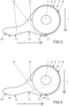
Fig.3 schematically shows the braking device fromFigure 2 in cross-section along lines III - III at rest, -
Fig.4 the braking device fromFigure 3 during a brake -
Fig.5 the braking device fromFigure 3 after acceleration -
Fig.6 shows another embodiment of the braking device in cross-section. -
Figure 1 schematically shows amotor vehicle 1 with anengine 2 and abraking device 3 forwheels 4. Thebraking device 3 has astator 5 with ahousing 6 and arotor 7 connected to at least one of thewheels 4. Therotor 7 is located near one end ofhousing 6 in the direction of travel of the motor vehicle. For clarification, the direction of travel ofmotor vehicle 1 is marked with an arrow. -
Figure 2 schematically shows the longitudinal section of thebraking device 3 for motor vehicles fromFigure 1 . Thebraking device 3 is designed as a multi-disc brake and has amulti-disc package 8 with alternately arranged axially movable pad discs 9 andintermediate discs 10. The lining discs 9 are torsion-resistant to therotor 7 and theintermediate discs 10 are torsion-resistant to thestator 5. An actuatingdevice 11 designed as a spreading device is supported on thestator 5. By spreading the spreading device by means of an actuator not shown, thefin package 8 is clamped and thus a flow of force from therotor 7 to thestator 5 is generated. Springs not shown release the tension of thelamellar pack 8 and thus the flow of force. For example, thecontrol 11 may be electric or hydraulic. -
Figure 3 schematically shows a cross-section through thebraking device 3 fromFigure 2 along lines III - III. Thepackage 6 of thestator 5 encloses thefin package 8 in afirst bulge 12 and has asecond bulge 13 distant from thefin package 8. Thebulges housing 6 and are separated from each other by means of a separating element designed as anindentation 14. Theindentation 14 removed from thelamella package 7 is arranged in the intended installation position against the direction of travel ofmotor vehicle 1 shown inFigure 1 . - The
braking device 3 has acooling device 15 for thefin pack 8 withliquid cooling medium 16 located in thehousing 6. The sub-area with thefirst bulge 12 ofhousing 6 comprising thedisc package 8 with thefirst bulge 12 forms acooling zone 17 of thebraking device 3. The part of thehousing 6 with thesecond bulge 13 removed from thefin package 8 forms areserve zone 18. In thereserve zone 18 there iscooling medium 16, which has no contact with thefin package 8 in the idle state shown. Coolingmedium 16 located in coolingzone 17 is in contact with thefin package 8 and allows it to be cooled. The coolingzone 17 and thereserve zone 18 are arranged at the same height and contain about the same amount of cooling medium 16 in the idle state shown, which corresponds, for example, to the new state. - When the
motor vehicle 1 withbraking device 3 brakes, the coolingmedium 16 ofreserve zone 18 sloshes into coolingzone 17, as shown inFigure 4 . This sloshing movement is due to the fact that coolingzone 17 is located in the direction of travel ofmotor vehicle 1 in front ofreserve zone 18. It can be seen that thefin package 8 is particularly deeply immersed in the coolingmedium 16 and thus has large contact surfaces with the coolingmedium 16. This leads to a particularly reliable cooling of thedisc pack 8 during braking. - The filling of cooling
zone 17 with cooling medium 16 shown inFigure 4 also occurs whenmotor vehicle 1 is driving downhill. During such a downhill journey, thebraking device 3 ofmotor vehicle 1 is usually subjected to particularly heavy loads. Due to the shape and orientation ofhousing 6, thebraking device 3 is also cooled particularly reliably during this downhill ride, because thefin pack 8 is immersed deep into the coolingmedium 16. -
Figure 5 shows the distribution of the refrigerant 16 in thecooling zone 17 and in thereserve zone 18 after a strong acceleration of themotor vehicle 1. In this case, a large part of the coolingmedium 16 sloshes out of thecooling zone 17 into thereserve zone 18 due to its mass inertia. This means that there is very little cooling medium in coolingzone 17 that can dissipate residual heat from thefin package 8. However, the small amount of cooling medium 16 in the area of thefin package 8 also leads to only a small residual torque in thefin package 8, so that friction losses of thefriction brake system 3 are particularly low. -
Figure 6 shows another embodiment of abraking device 103, which differs from that shown inFigure 3 in that areserve zone 118 and acooling zone 117 enclosing afin pack 108 are connected to each other by achannel 119. Inchannel 119, a check valve orvalve 120 is arranged, which controls a distribution of cooling medium 116 between the coolingzone 117 and thereserve zone 118. The check valve orvalve 120 thus forms a separating element betweencooling zone 117 andreserve zone 118. Thecooling zone 117 and thereserve zone 118 are formed asbulges casing 106, wherein thebulges indentation 114. Otherwise, thisbraking device 103 is constructed in the same way as the one fromFigure 3 . - Additionally and especially in accomplishing the effectively closed energy circle, any embodiment of the explained friction brake system can be provided with a heat pump system HP,
HP 1, HP2 that allows for regenerative green capabilities in terms of reliable, eco-friendly and thereby productive cooling fluid energy conversion. Consequently any heat that is stored for friction brake reasons in a cooling fluid can usefully be converted and made available for its electric use in automotive electric energy network of a vehicle. -
- 1 motor vehicle
- 2 engine
- 3, 103 friction brake system
- 4 wheel
- 5 stator
- 6, 106 cases
- 7 rotor
- 8, 108 lamellar pack
- 9 pad disc
- 10 intermediate disc
- 11 control device
- 12, 112, 13, 113 bulge
- 14 indentation
- 15 cooling device
- 16, 116 cooling medium
- 17, 117 cooling zone
- 18, 118 reserve zone
- 119 channel
- 120 valve
- g gravitational force (direction)
- HP, HP1, HP2 Heat Pump
- M Motor/Drivetrain (of vehicle)
- v Motion direction (of vehicle)
Claims (13)
- Automotive friction brake system (3, 103) for a motor vehicle (1) with a stator (5), with a rotor (7) which can be rotated relative to the stator (5), with an actuating device (11) for friction brake apply or friction brake release thereby affecting frictional condition between the stator (5) and the rotor (7) and with a cooling device (15) comprising a liquid cooling medium (16, 116) for dissipating heat in friction brake apply, characterized by the fact that the stator (5) comprises a cooling zone (17, 117) that at least partially accommodates the rotor (7) and the stator (5) comprising a reserve zone (18, 118) in distance from the rotor (7) and the cooling zone (17, 117), and wherein the cooling zone (17, 117) absorbs more cooling medium (16, 116) during friction brake apply than during friction brake release.
- Automotive friction brake system (3, 103) according to claim 1, characterized in that the cooling zone (17, 117) is arranged in the intended direction of travel of the motor vehicle in front of the reserve zone (18, 118).
- Automotive friction brake system (3, 103) according to claim 1 or 2, characterized in that in the intended installation position of the cooling device (15) in the motor vehicle (1) the cooling zone (17, 117) and the reserve zone (18, 118) are arranged at the same height.
- Automotive friction brake system (3, 103) according to at least one of claims 1 to 3, characterized in that the stator (5) has a housing (6, 106) and that the housing (6, 106) has the cooling zone (17, 117) and the reserve zone (18, 118).
- Automotive friction brake system (3, 103) according to at least one of claims 1 to 4, characterized in that the cooling zone (17, 117) and the reserve zone (18, 118) are separated from each other by a separating element.
- Automotive friction brake system (3, 103) according to at least one of claims 1 to 5, characterized in that the cooling zone (17, 117) and the reserve zone (18,118) are both compartments.
- Automotive friction brake system (3, 103) according to at least one of claims 4 to 6, characterized in that the cooling zone (17, 117) and the reserve zone (18, 118) are each formed as bulges (12, 112, 13, 113) of the housing (6, 106).
- Automotive friction brake system (3, 103) according to at least one of claims 1 to 7, characterized in that the cooling zone (117) and the reserve zone (118) are connected to each other by a channel (119).
- Automotive friction brake system (3, 103) according to at least one of claims 1 to 8, characterized in that a flap or valve (120) is arranged between the cooling zone (17) and the reserve zone (118).
- Automotive friction brake system (3, 103) and/or friction brake fluid cooling process according to at least one of claims 1 - 9, characterized in that natural gravity force (g) constitutes currentless constant energy driver for automatic collection, backfeed, recirculation, equalization or fluid level niveau concerning liquid cooling medium and/or automatic storing liquid cooling medium in at least one zone (17,117;18,118).
- Automotive friction brake system (3, 103) and/or friction brake fluid cooling process according to at least one of claims 1 - 10, characterized in that fluidic inertial reaction force constitutes the currentless energy driver for automatic zone change of fluidic cooling medium volume, especially in the direction of vehicular forward motion (v) when leaving from reserve zone (18,118) into cooling zone (17,117).
- Automotive friction brake system (3, 103) according to at least one of claims 1 to 11, characterized in that the friction brake system (3, 103) is designed as a multiplate brake with alternately arranged axially movable pad discs (9) and intermediate discs (10) of a multi-disc pack (8, 108), wherein the lining discs (9) are torsionally connected to the rotor (7) or the stator (5) and the intermediate discs (10) are torsionally connected to the opposite component of the stator (5) or the rotor (7), that the control (11) has means for clamping the fin pack (8) to generate a frictional flow of force and to release the tension of the fin pack (8, 108) and for releasing the frictional flow of force, and that the cooling zone (17, 117) comprises at least part of the fin pack (8, 108) and that the reserve zone (18, 118) is located outside the fin pack (8, 108).
- Automotive friction brake system (3,103) according to anyone of claims 1-12, characterized in that at least one or more heat pump system (HP, HP1, HP2) are included in the friction brake system which heat pump system (HP,HP1 ,HP2) is preferably either integrated in the cooling fluid circulation itself and/or in any one of the zones (17,117;18,118) of stator (5), and wherein the at least one heat pump system (HP, HP1, HP2) serves for friction brake energy regeneration so that cooling fluid heat energy is converted into electric energy.
Priority Applications (1)
| Application Number | Priority Date | Filing Date | Title |
|---|---|---|---|
| EP23194236.8A EP4517125A1 (en) | 2023-08-30 | 2023-08-30 | Automotive friction brake system |
Applications Claiming Priority (1)
| Application Number | Priority Date | Filing Date | Title |
|---|---|---|---|
| EP23194236.8A EP4517125A1 (en) | 2023-08-30 | 2023-08-30 | Automotive friction brake system |
Publications (1)
| Publication Number | Publication Date |
|---|---|
| EP4517125A1 true EP4517125A1 (en) | 2025-03-05 |
Family
ID=87863328
Family Applications (1)
| Application Number | Title | Priority Date | Filing Date |
|---|---|---|---|
| EP23194236.8A Pending EP4517125A1 (en) | 2023-08-30 | 2023-08-30 | Automotive friction brake system |
Country Status (1)
| Country | Link |
|---|---|
| EP (1) | EP4517125A1 (en) |
Citations (3)
| Publication number | Priority date | Publication date | Assignee | Title |
|---|---|---|---|---|
| US8235183B2 (en) * | 2008-02-25 | 2012-08-07 | Ausco Products, Inc. | Ball ramp brake |
| DE102019208226B3 (en) | 2019-06-05 | 2020-10-22 | Continental Teves Ag & Co. Ohg | Multi-disc brake for a motor vehicle |
| DE202019005826U1 (en) * | 2019-09-13 | 2022-05-17 | Dana Italia S.R.L. | Wet braking system and vehicle incorporating this braking system |
-
2023
- 2023-08-30 EP EP23194236.8A patent/EP4517125A1/en active Pending
Patent Citations (3)
| Publication number | Priority date | Publication date | Assignee | Title |
|---|---|---|---|---|
| US8235183B2 (en) * | 2008-02-25 | 2012-08-07 | Ausco Products, Inc. | Ball ramp brake |
| DE102019208226B3 (en) | 2019-06-05 | 2020-10-22 | Continental Teves Ag & Co. Ohg | Multi-disc brake for a motor vehicle |
| DE202019005826U1 (en) * | 2019-09-13 | 2022-05-17 | Dana Italia S.R.L. | Wet braking system and vehicle incorporating this braking system |
Similar Documents
| Publication | Publication Date | Title |
|---|---|---|
| JP7491344B2 (en) | Motor Unit | |
| JP7544220B2 (en) | Motor Unit | |
| CN121179973A (en) | Powertrain for multi-purpose vehicles | |
| JP2013523504A (en) | Automotive drivetrain | |
| JP2008514506A (en) | Hybrid hydraulic drive | |
| CN108349373A (en) | Transmission system for vehicle and the vehicle including the transmission system | |
| US8607664B2 (en) | Fluid motion control device | |
| JP2009541129A (en) | Fluid retarder | |
| US11268578B2 (en) | Slip clutch comprising an axis of rotation | |
| CN110803145B (en) | Braking system of road roller, road roller and control method | |
| EP0592603A4 (en) | Direct drive axle brake and cooling system. | |
| CN104204595A (en) | Integrated retarder and friction brake | |
| MX2007007132A (en) | Compact helical compressor for mobile use in a vehicle. | |
| US5207305A (en) | Method and apparatus for incorporating hydrodynamic film to transfer or retard motion and dissipate heat | |
| JP7685010B2 (en) | Cooling system for automotive electric motors | |
| CN118369528A (en) | Electrically operable axle drivetrain | |
| CA2971404A1 (en) | Heat pipe cooled wet rotating disc engagement systems | |
| JP2010031984A (en) | Vehicular driving device | |
| CN113915256A (en) | Elastic damping type gear shifting brake | |
| JP4894570B2 (en) | In-wheel motor | |
| US4994003A (en) | Apparatus using aerodynamic rotors for exerting a braking torque upon a rotating shaft | |
| JP2015218867A (en) | Oil supply device | |
| JP6799492B2 (en) | Electric motor cooling device | |
| CN111417549B (en) | Start and deceleration module | |
| JPH0366932A (en) | Friction coupling, brake assembly, clutch assembly, speed changer assembly, method of transmitting torque and heat and method of designing friction coupling |
Legal Events
| Date | Code | Title | Description |
|---|---|---|---|
| PUAI | Public reference made under article 153(3) epc to a published international application that has entered the european phase |
Free format text: ORIGINAL CODE: 0009012 |
|
| STAA | Information on the status of an ep patent application or granted ep patent |
Free format text: STATUS: THE APPLICATION HAS BEEN PUBLISHED |
|
| AK | Designated contracting states |
Kind code of ref document: A1 Designated state(s): AL AT BE BG CH CY CZ DE DK EE ES FI FR GB GR HR HU IE IS IT LI LT LU LV MC ME MK MT NL NO PL PT RO RS SE SI SK SM TR |
|
| STAA | Information on the status of an ep patent application or granted ep patent |
Free format text: STATUS: REQUEST FOR EXAMINATION WAS MADE |
|
| 17P | Request for examination filed |
Effective date: 20250905 |
|
| RAP3 | Party data changed (applicant data changed or rights of an application transferred) |
Owner name: AUMOVIO GERMANY GMBH |