EP4517112A1 - Size-adjustable fastener - Google Patents
Size-adjustable fastener Download PDFInfo
- Publication number
- EP4517112A1 EP4517112A1 EP24196747.0A EP24196747A EP4517112A1 EP 4517112 A1 EP4517112 A1 EP 4517112A1 EP 24196747 A EP24196747 A EP 24196747A EP 4517112 A1 EP4517112 A1 EP 4517112A1
- Authority
- EP
- European Patent Office
- Prior art keywords
- fastener
- hole
- connection
- limiting
- bolt
- Prior art date
- Legal status (The legal status is an assumption and is not a legal conclusion. Google has not performed a legal analysis and makes no representation as to the accuracy of the status listed.)
- Pending
Links
Images



Classifications
-
- F—MECHANICAL ENGINEERING; LIGHTING; HEATING; WEAPONS; BLASTING
- F16—ENGINEERING ELEMENTS AND UNITS; GENERAL MEASURES FOR PRODUCING AND MAINTAINING EFFECTIVE FUNCTIONING OF MACHINES OR INSTALLATIONS; THERMAL INSULATION IN GENERAL
- F16B—DEVICES FOR FASTENING OR SECURING CONSTRUCTIONAL ELEMENTS OR MACHINE PARTS TOGETHER, e.g. NAILS, BOLTS, CIRCLIPS, CLAMPS, CLIPS OR WEDGES; JOINTS OR JOINTING
- F16B2/00—Friction-grip releasable fastenings
- F16B2/02—Clamps, i.e. with gripping action effected by positive means other than the inherent resistance to deformation of the material of the fastening
- F16B2/06—Clamps, i.e. with gripping action effected by positive means other than the inherent resistance to deformation of the material of the fastening external, i.e. with contracting action
- F16B2/08—Clamps, i.e. with gripping action effected by positive means other than the inherent resistance to deformation of the material of the fastening external, i.e. with contracting action using bands
-
- B—PERFORMING OPERATIONS; TRANSPORTING
- B65—CONVEYING; PACKING; STORING; HANDLING THIN OR FILAMENTARY MATERIAL
- B65D—CONTAINERS FOR STORAGE OR TRANSPORT OF ARTICLES OR MATERIALS, e.g. BAGS, BARRELS, BOTTLES, BOXES, CANS, CARTONS, CRATES, DRUMS, JARS, TANKS, HOPPERS, FORWARDING CONTAINERS; ACCESSORIES, CLOSURES, OR FITTINGS THEREFOR; PACKAGING ELEMENTS; PACKAGES
- B65D63/00—Flexible elongated elements, e.g. straps, for bundling or supporting articles
- B65D63/10—Non-metallic straps, tapes, or bands; Filamentary elements, e.g. strings, threads or wires; Joints between ends thereof
- B65D63/1018—Joints produced by application of integral securing members, e.g. buckles, wedges, tongue and slot, locking head and teeth or the like
- B65D63/1027—Joints produced by application of integral securing members, e.g. buckles, wedges, tongue and slot, locking head and teeth or the like the integral securing member being formed as a female and male locking member, e.g. locking head and locking teeth, or the like
-
- F—MECHANICAL ENGINEERING; LIGHTING; HEATING; WEAPONS; BLASTING
- F16—ENGINEERING ELEMENTS AND UNITS; GENERAL MEASURES FOR PRODUCING AND MAINTAINING EFFECTIVE FUNCTIONING OF MACHINES OR INSTALLATIONS; THERMAL INSULATION IN GENERAL
- F16B—DEVICES FOR FASTENING OR SECURING CONSTRUCTIONAL ELEMENTS OR MACHINE PARTS TOGETHER, e.g. NAILS, BOLTS, CIRCLIPS, CLAMPS, CLIPS OR WEDGES; JOINTS OR JOINTING
- F16B21/00—Means for preventing relative axial movement of a pin, spigot, shaft or the like and a member surrounding it; Stud-and-socket releasable fastenings
- F16B21/09—Releasable fastening devices with a stud engaging a keyhole slot
-
- B—PERFORMING OPERATIONS; TRANSPORTING
- B65—CONVEYING; PACKING; STORING; HANDLING THIN OR FILAMENTARY MATERIAL
- B65D—CONTAINERS FOR STORAGE OR TRANSPORT OF ARTICLES OR MATERIALS, e.g. BAGS, BARRELS, BOTTLES, BOXES, CANS, CARTONS, CRATES, DRUMS, JARS, TANKS, HOPPERS, FORWARDING CONTAINERS; ACCESSORIES, CLOSURES, OR FITTINGS THEREFOR; PACKAGING ELEMENTS; PACKAGES
- B65D2563/00—Flexible elongated elements, e.g. straps for bundling or supporting atricles
- B65D2563/10—Non-metallic straps, tapes or bands; Filamentary elements, e.g. strings, threads, wires; Joints between ends thereof
- B65D2563/101—Details of non-metallic straps, tapes or bands
-
- F—MECHANICAL ENGINEERING; LIGHTING; HEATING; WEAPONS; BLASTING
- F16—ENGINEERING ELEMENTS AND UNITS; GENERAL MEASURES FOR PRODUCING AND MAINTAINING EFFECTIVE FUNCTIONING OF MACHINES OR INSTALLATIONS; THERMAL INSULATION IN GENERAL
- F16B—DEVICES FOR FASTENING OR SECURING CONSTRUCTIONAL ELEMENTS OR MACHINE PARTS TOGETHER, e.g. NAILS, BOLTS, CIRCLIPS, CLAMPS, CLIPS OR WEDGES; JOINTS OR JOINTING
- F16B3/00—Key-type connections; Keys
-
- F—MECHANICAL ENGINEERING; LIGHTING; HEATING; WEAPONS; BLASTING
- F16—ENGINEERING ELEMENTS AND UNITS; GENERAL MEASURES FOR PRODUCING AND MAINTAINING EFFECTIVE FUNCTIONING OF MACHINES OR INSTALLATIONS; THERMAL INSULATION IN GENERAL
- F16B—DEVICES FOR FASTENING OR SECURING CONSTRUCTIONAL ELEMENTS OR MACHINE PARTS TOGETHER, e.g. NAILS, BOLTS, CIRCLIPS, CLAMPS, CLIPS OR WEDGES; JOINTS OR JOINTING
- F16B35/00—Screw-bolts; Stay-bolts; Screw-threaded studs; Screws; Set screws
-
- F—MECHANICAL ENGINEERING; LIGHTING; HEATING; WEAPONS; BLASTING
- F16—ENGINEERING ELEMENTS AND UNITS; GENERAL MEASURES FOR PRODUCING AND MAINTAINING EFFECTIVE FUNCTIONING OF MACHINES OR INSTALLATIONS; THERMAL INSULATION IN GENERAL
- F16B—DEVICES FOR FASTENING OR SECURING CONSTRUCTIONAL ELEMENTS OR MACHINE PARTS TOGETHER, e.g. NAILS, BOLTS, CIRCLIPS, CLAMPS, CLIPS OR WEDGES; JOINTS OR JOINTING
- F16B37/00—Nuts or like thread-engaging members
Definitions
- the present disclosure relates to the field of connection structures, and in particular to a size-adjustable fastener.
- carry-on objects may usually need to be fixed to other structures.
- a camping light may need to be fixed to a camping pole;
- a bottle needs to be fixed to a seat post of a bicycle, and
- a bag needs to be fixed to a handlebar of the bicycle.
- the above fixing is achieved by a fastener.
- fixing the bag to the handlebar of the bicycle will be described as an example.
- a bicycle fastener in the art is a ring-shaped structure sleeving the handlebar.
- a diameter of a through hole on the ring-shaped structure is not adjustable.
- a patent, having an application No. 202222458753.X discloses a fastener connection structure for an outdoor bag and a bicycle handlebar.
- the fastener connection structure includes a bag body, a fastener member and a fixed plate fixed at a front end of the bag body.
- a bottom of the fixed plate is fixed with an insertion-connection member.
- a top of the insertion-connection defines an opening. The opening gradually decreases along a direction extending from an outside to an inside.
- the insertion-connection member defines an opened limiting groove communicating with the opening.
- the fastener member includes a limiting slider, two first fixing rings and two second fixing rings.
- the limiting slider is slidably arranged in the opened limiting groove.
- the insertion-connection member is located at a middle of the opening and defines a square limiting groove.
- a bottom of the limiting slider is provided with a limiting assembly corresponding to the square limiting groove.
- the two first fixing rings are both fixed on the limiting slider.
- An end of the second fixing ring is hinged to a bottom of the first fixing ring.
- a top of the first fixing ring defines a through hole.
- a top of the second fixing ring defines a thread hole mating with the through hole.
- a fixing bolt is fixedly threaded inside the threaded hole.
- a circular through hole is defined cooperatively by the first fixing ring and the second fixing ring.
- the bicycle handlebar passes through the circular through hole.
- the first fixing ring and the second fixing ring cooperatively clamp the bicycle handlebar.
- the first fixing ring and the second fixing ring are connected to each other via fixing screws.
- a diameter of the fastener member mounted on the bicycle handlebar is not adjustable. When the diameter of the bicycle handlebar is larger than the diameter of the through hole, the first fixing ring and the second fixing ring cannot sleeve the bicycle handlebar, and therefore, the fastener connection structure cannot be mounted to the bicycle handlebar.
- the first fixing ring and the second fixing ring sleeve the bicycle handlebar, however, the first fixing ring and the second fixing ring cannot be tightly fastened to the bicycle handlebar.
- the bicycle may bump, resulting in the first fixing ring and the second fixing ring rotating around the bicycle handlebar and colliding with other structures of the bicycle.
- the present disclosure provides a size-adjustable fastener to solve a technical problem that a size of the fastener is not adjustable.
- the present disclosure provides a size-adjustable fastener, including: a first fastener and a second fastener.
- the first fastener is arranged with a plurality of connection strips; an end of each of the plurality of connection strips is arranged with a limiting block; a transverse cross section of the limiting block is larger than that of the connection strip;
- the second fastener defines a plurality of connection holes; each of the plurality of connection holes is communicated with a limiting hole, and the limiting hole is located at a side of the respective connection hole;
- the connection strip is inserted into the connection hole from a side of the second fastener; the connection strip is moved to approach the limiting hole to enable the limiting block to abut against the other side of the second fastener, enabling an end of the second fastener is connected to an end of the first fastener.
- the other end of the second fastener is connected to the other end of the first fastener.
- two ends of a side of the connection strip defines two limiting grooves, respectively; a length of the limiting hole is smaller than a length of the connection hole; two limiting projections are formed at connections between the connection hole and the limiting hole; when the connection strip is moved to approach the limiting hole, the two limiting projections are respectively snapped into the two limiting grooves.
- a side of the limiting block facing the limiting slots horizontally protrudes out of the side of the connection strip.
- the number of the plurality of connection strips is at least three, and the number of the plurality of connection holes is more than the number of the plurality of connection strips.
- the other end of the second fastener is arranged with a bolt
- the other end of the first fastener is arranged with a fastening nut
- the bolt is screwed tightly with the fastening nut to enable the other end of the second fastener to be connected to the other end of the first fastener.
- an auxiliary hole is defined between the plurality of connection holes and the bolt; and the end of the second fastener away from the bolt passes through the auxiliary hole.
- the second fastener defines a bolt hole; the bolt extends through the bolt hole; the fastening nut defines a screw hole; the bolt is screwed into the screw hole, enabling the other end of the first fastener to be connected to the other end of the second fastener.
- the bolt hole is communicated with a receiving slot, the receiving slot is configured to receive a head of the bolt.
- the first fastener defines a nut hole, an inner wall of the nut hole is arranged with internal threads, the fastening nut is arranged with external threads, the nut is mounted in the nut hole by threading the external threads with the internal threads.
- a size-adjustable fastener includes a first fastener and a second fastener. An end of the second fastener is connected to an end of the first fastener.
- the second fastener defines a plurality of connection holes.
- a connection strip on the first fastener selectively passes through any one of the plurality of connection holes, and therefore, a diameter of a through hole defined by the second fastener and the first fastener is adjustable.
- the connection strip is limited in the connection hole by a limiting block. In this way, connection between the end of the second fastener and the end of the first fastener is achieved.
- a simple structure is configured to enable the diameter of the through hole to be adjustable.
- the size-adjustable fastener in the present disclosure is highly practical and has low production costs.
- first fastener 100, first fastener; 110, connection strip; 111, limiting groove; 120, limiting block; 130, fastening nut; 131, screw hole; 140, nut hole; 200, second fastener; 210, connection hole; 220, limiting hole; 230, limiting projection; 240, bolt; 250, auxiliary hole; 260, bolt hole; 270, receiving slot.
- the present disclosure provides a fastener configured to fasten a carry-on object to a strip-shaped structure.
- the carry-on object includes, but is not limited to, a bottle and a bag.
- the strip-shaped structure includes, but is not limited to, a seat post of a bicycle and a bicycle handlebar.
- a size-adjustable fastener includes a first fastener 100 and a second fastener 200.
- the first fastener 100 and the second fastener 200 are both elongated, thin, and bendable. Specifically, the first fastener 100 and the second fastener 200 enclose, under an external force, with each other to form an annular structure having a through hole.
- the through hole is configured to allow the strip-shaped structure to pass through. That is, the first fastener 100 and the second fastener 200 sleeve the strip-shaped structure.
- the first fastener 100 is arranged with a plurality of connection strips 110.
- An end of each connection strip 110 is arranged with a limiting block 120.
- a transverse cross section of the limiting block 120 is larger than that of the connection strip 110.
- the second fastener 200 defines a plurality of connection holes 210.
- Each connection hole 210 is communicated with a limiting hole 220, and the limiting hole 220 is located at a side of the connection hole 210.
- the connection strip 110 is inserted into the connection hole 210 from a side of the second fastener 200.
- the connection strip 110 is moved to approach the limiting hole 220 to enable the limiting block 120 to abut against the other side of the second fastener 200.
- the end of the second fastener 200 is connected to the end of the first fastener 100.
- the other end of the second fastener 200 away from the plurality of connection holes 210 is connected to the other end of the first fastener 100 away from the plurality of connection strips 110. Since the plurality of connection holes 210 are defined, when the first fastener 100 and the second fastener 200 surround the strip-shaped structure, and the connection strip 110 can be inserted into a proper one of the plurality of connection holes 210 based on a diameter of the strip-shaped structure.
- the first fastener 100 and the second fastener 200 can be tightly fastened on the strip-shaped structure, and therefore, a diameter of the through hole defined by the first fastener 100 and the second fastener 200 is adjustable.
- the connection strip 110 is enabled to be disposed close to the limiting hole 220 (for example, eventually, the force enables at least a portion of the connection strip 110 to be received in the limiting hole 220). Therefore, the limiting block 120 abuts against the other side of the second fastener 200.
- the limiting block 120 prevents the connection strip 110 from sliding out of the connection hole 210, such that the end of the first fastener 100 is connected to the end of the second fastener 200.
- a simple structure is configured to allow the diameter of the through hole to be adjustable, and therefore, the size-adjustable fastener in the present disclosure is highly practical and has low production costs.
- two ends of a side of the connection strip 110 defines two limiting grooves 111, respectively.
- a length of the limiting hole 220 is smaller than a length of the connection hole 210 (the length refers to a size of the limiting hole or the connection hole in a direction perpendicular to a length direction of the second fastener 200).
- Two limiting projections 230 are formed at connections between the connection hole 210 and the limiting hole 220.
- the first fastener 100 and the second fastener 200 surround and are fastened to the strip-shaped structure based on the diameter of the strip-shaped structure, due to an outward reaction force that the strip-shaped structure applies on the first fastener 100 and the second fastener 200, the first fastener 100 and the second fastener 200 are moved away from each other to enable the connection strip 110 to approach the limiting hole 220, enabling the two limiting projections 230 to be respectively snapped into the two limiting grooves 111. That is, an area that the limiting block 120 abuts against the other side of the first fastener 100 is increased. In this way, the connection strip 110 is further prevented from being disengaged out of the connection hole 210.
- a protruded portion of the limiting block 120 is configured to abut against the other side of the second fastener 200, preventing the connection strip 110 from slipping out of the connection hole 210.
- connection strips 110 are arranged.
- the number of the plurality of connection holes 210 is more than the number of the connection strips 110.
- Three of the at least three connection strips 110 are respectively inserted into three of the plurality of connection holes 210. Arranging three connection strips 110 allows the first fastener 100 and the second fastener 200 to be more securely connected to each other, and the first fastener 100 and the second fastener 200 are less likely to be detached from each other.
- the other end of the second fastener 200 is arranged with a bolt 240, and the other end of the first fastener 100 is arranged with a fastening nut 130.
- the bolt 240 is screwed tightly with the fastening nut 130 to enable the other end of the second fastener 200 to be connected to the other end of the first fastener 100. In this way, detachable connection between the first fastener 100 and the second fastener 200 is achieved, and detaching can be performed easily.
- an auxiliary hole 250 is defined between the connection hole 210 and the bolt 240, and the end of the second fastener 200 away from the bolt 240 passes through the auxiliary hole 250.
- the end of the second fastener 200 extends around for one loop to pass through the auxiliary hole 250 (i.e., the end of the second fastener 200 extends into the auxiliary hole 250 from the other side of the second fastener 200). In this way, an aesthetical structure is achieved.
- the second fastener 200 defines a bolt hole 260.
- the bolt 240 extends through the bolt hole 260.
- the fastening nut 130 defines a screw hole 131.
- the bolt 240 is screwed into the screw hole 131.
- the other end of the first fastener 100 is enabled to be connected to the other end of the second fastener 200. That is, the bolt 240 passes through the bolt hole 260 and the screw hole 131 sequentially to connect the other end of the second fastener 200 to the other end of the first fastener 100.
- the bolt hole 260 is communicated with a receiving slot 270.
- the receiving slot 270 is configured to receive a head of the bolt 240.
- the head of the bolt 240 is received in the receiving slot 270.
- an outer surface of the head of the bolt 240 flushes with a surface of the second fastener 200.
- An aesthetical structure is achieved.
- the first fastener 100 defines a nut hole 140.
- An inner wall of the nut hole 140 is arranged with internal threads.
- the fastening nut 130 is arranged with external threads.
- the nut is mounted in the nut hole 140 by threading the external threads with the internal threads. Since the fastening nut 130 is tightly fastened in the nut hole 140 and connection there between is achieved by the external threads being threaded with the internal threads, the fastening nut 130 does not rotate when the bolt 240 is screwed into the fastening nut 130.
Landscapes
- Engineering & Computer Science (AREA)
- General Engineering & Computer Science (AREA)
- Mechanical Engineering (AREA)
- Connection Of Plates (AREA)
- Buckles (AREA)
Abstract
Description
- The present disclosure relates to the field of connection structures, and in particular to a size-adjustable fastener.
- In daily life or outdoor activities, carry-on objects (a bottle, a bag, and so on) may usually need to be fixed to other structures. For example, when camping, a camping light may need to be fixed to a camping pole; when riding, a bottle needs to be fixed to a seat post of a bicycle, and a bag needs to be fixed to a handlebar of the bicycle. The above fixing is achieved by a fastener. In the following, fixing the bag to the handlebar of the bicycle will be described as an example.
- A bicycle fastener in the art is a ring-shaped structure sleeving the handlebar. A diameter of a through hole on the ring-shaped structure is not adjustable. For example, a patent, having an application No.
202222458753.X - The present disclosure provides a size-adjustable fastener to solve a technical problem that a size of the fastener is not adjustable.
- The present disclosure provides a size-adjustable fastener, including: a first fastener and a second fastener. The first fastener is arranged with a plurality of connection strips; an end of each of the plurality of connection strips is arranged with a limiting block; a transverse cross section of the limiting block is larger than that of the connection strip; the second fastener defines a plurality of connection holes; each of the plurality of connection holes is communicated with a limiting hole, and the limiting hole is located at a side of the respective connection hole; the connection strip is inserted into the connection hole from a side of the second fastener; the connection strip is moved to approach the limiting hole to enable the limiting block to abut against the other side of the second fastener, enabling an end of the second fastener is connected to an end of the first fastener. The other end of the second fastener is connected to the other end of the first fastener.
- In some embodiments, two ends of a side of the connection strip defines two limiting grooves, respectively; a length of the limiting hole is smaller than a length of the connection hole; two limiting projections are formed at connections between the connection hole and the limiting hole; when the connection strip is moved to approach the limiting hole, the two limiting projections are respectively snapped into the two limiting grooves.
- In some embodiments, a side of the limiting block facing the limiting slots horizontally protrudes out of the side of the connection strip.
- In some embodiments, the number of the plurality of connection strips is at least three, and the number of the plurality of connection holes is more than the number of the plurality of connection strips.
- In some embodiments, the other end of the second fastener is arranged with a bolt, and the other end of the first fastener is arranged with a fastening nut; the bolt is screwed tightly with the fastening nut to enable the other end of the second fastener to be connected to the other end of the first fastener.
- In some embodiments, an auxiliary hole is defined between the plurality of connection holes and the bolt; and the end of the second fastener away from the bolt passes through the auxiliary hole.
- In some embodiments, the second fastener defines a bolt hole; the bolt extends through the bolt hole; the fastening nut defines a screw hole; the bolt is screwed into the screw hole, enabling the other end of the first fastener to be connected to the other end of the second fastener.
- In some embodiments, the bolt hole is communicated with a receiving slot, the receiving slot is configured to receive a head of the bolt.
- In some embodiments, the first fastener defines a nut hole, an inner wall of the nut hole is arranged with internal threads, the fastening nut is arranged with external threads, the nut is mounted in the nut hole by threading the external threads with the internal threads.
- According to the present disclosure, a size-adjustable fastener is provided and includes a first fastener and a second fastener. An end of the second fastener is connected to an end of the first fastener. The second fastener defines a plurality of connection holes. A connection strip on the first fastener selectively passes through any one of the plurality of connection holes, and therefore, a diameter of a through hole defined by the second fastener and the first fastener is adjustable. In addition, the connection strip is limited in the connection hole by a limiting block. In this way, connection between the end of the second fastener and the end of the first fastener is achieved. In the present disclosure, a simple structure is configured to enable the diameter of the through hole to be adjustable. The size-adjustable fastener in the present disclosure is highly practical and has low production costs.
-
-
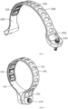
FIG. 1 is a first structural schematic view of a size-adjustable fastener according to an embodiment of the present disclosure. -
FIG. 2 is a second structural schematic view of the size-adjustable fastener according to an embodiment of the present disclosure. -
FIG. 3 is a structural schematic view of a first fastener according to an embodiment of the present disclosure. -
FIG. 4 is a bottom view of the first fastener according to an embodiment of the present disclosure. -
FIG. 5 is a cross-sectional view of the first fastener shown inFIG. 4 , taken along a line A-A. -
FIG. 6 is a structural schematic view of a second fastener according to an embodiment of the present disclosure. -
FIG. 7 is a structural schematic view of the size-adjustable fastener in a bent state according to an embodiment of the present disclosure. -
FIG. 8 is a structural schematic view I of the size-adjustable fastener in a mounted state according to an embodiment of the present disclosure. -
FIG. 9 is a structural schematic view II of the size-adjustable fastener in the mounted state according to an embodiment of the present disclosure. - Reference numerals in the drawings: 100, first fastener; 110, connection strip; 111, limiting groove; 120, limiting block; 130, fastening nut; 131, screw hole; 140, nut hole; 200, second fastener; 210, connection hole; 220, limiting hole; 230, limiting projection; 240, bolt; 250, auxiliary hole; 260, bolt hole; 270, receiving slot.
- In order to make the purpose, technical solutions and advantages of the embodiments of the present disclosure clearer, the technical solutions in the embodiments of the present disclosure will be described clearly and completely in the following by referring to the accompanying drawings in the embodiments of the present disclosure. Obviously, the described embodiments are a part of, not all of, the embodiments of the present disclosure. All other embodiments, which are obtained by any ordinary skilled person in the art based on the embodiments in the present disclosure without making creative work, shall fall within the scope of the present disclosure.
- The present disclosure provides a fastener configured to fasten a carry-on object to a strip-shaped structure. The carry-on object includes, but is not limited to, a bottle and a bag. The strip-shaped structure includes, but is not limited to, a seat post of a bicycle and a bicycle handlebar.
- As shown in
FIGS. 1-FIG. 9 , a size-adjustable fastener is provided and includes afirst fastener 100 and asecond fastener 200. Thefirst fastener 100 and thesecond fastener 200 are both elongated, thin, and bendable. Specifically, thefirst fastener 100 and thesecond fastener 200 enclose, under an external force, with each other to form an annular structure having a through hole. The through hole is configured to allow the strip-shaped structure to pass through. That is, thefirst fastener 100 and thesecond fastener 200 sleeve the strip-shaped structure. - The
first fastener 100 is arranged with a plurality of connection strips 110. An end of eachconnection strip 110 is arranged with a limitingblock 120. A transverse cross section of the limitingblock 120 is larger than that of theconnection strip 110. Thesecond fastener 200 defines a plurality of connection holes 210. Eachconnection hole 210 is communicated with a limitinghole 220, and the limitinghole 220 is located at a side of theconnection hole 210. Theconnection strip 110 is inserted into theconnection hole 210 from a side of thesecond fastener 200. In addition, theconnection strip 110 is moved to approach the limitinghole 220 to enable the limitingblock 120 to abut against the other side of thesecond fastener 200. In this way, the end of thesecond fastener 200 is connected to the end of thefirst fastener 100. The other end of thesecond fastener 200 away from the plurality of connection holes 210 is connected to the other end of thefirst fastener 100 away from the plurality of connection strips 110. Since the plurality of connection holes 210 are defined, when thefirst fastener 100 and thesecond fastener 200 surround the strip-shaped structure, and theconnection strip 110 can be inserted into a proper one of the plurality of connection holes 210 based on a diameter of the strip-shaped structure. In this way, thefirst fastener 100 and thesecond fastener 200 can be tightly fastened on the strip-shaped structure, and therefore, a diameter of the through hole defined by thefirst fastener 100 and thesecond fastener 200 is adjustable. In addition, due to a force that the strip-shaped structure applied on thefirst fastener 100 and thesecond fastener 200, theconnection strip 110 is enabled to be disposed close to the limiting hole 220 (for example, eventually, the force enables at least a portion of theconnection strip 110 to be received in the limiting hole 220). Therefore, the limitingblock 120 abuts against the other side of thesecond fastener 200. The limitingblock 120 prevents theconnection strip 110 from sliding out of theconnection hole 210, such that the end of thefirst fastener 100 is connected to the end of thesecond fastener 200. In the present disclosure, a simple structure is configured to allow the diameter of the through hole to be adjustable, and therefore, the size-adjustable fastener in the present disclosure is highly practical and has low production costs. - In the present embodiment, two ends of a side of the
connection strip 110 defines two limitinggrooves 111, respectively. A length of the limitinghole 220 is smaller than a length of the connection hole 210 (the length refers to a size of the limiting hole or the connection hole in a direction perpendicular to a length direction of the second fastener 200). Two limitingprojections 230 are formed at connections between theconnection hole 210 and the limitinghole 220. When thefirst fastener 100 and thesecond fastener 200 surround and are fastened to the strip-shaped structure based on the diameter of the strip-shaped structure, due to an outward reaction force that the strip-shaped structure applies on thefirst fastener 100 and thesecond fastener 200, thefirst fastener 100 and thesecond fastener 200 are moved away from each other to enable theconnection strip 110 to approach the limitinghole 220, enabling the two limitingprojections 230 to be respectively snapped into the two limitinggrooves 111. That is, an area that the limitingblock 120 abuts against the other side of thefirst fastener 100 is increased. In this way, theconnection strip 110 is further prevented from being disengaged out of theconnection hole 210. - In the present embodiment, a side of the limiting
block 120 facing the limitingslots 111 horizontally protrudes out of the side of theconnection strip 110. A protruded portion of the limitingblock 120 is configured to abut against the other side of thesecond fastener 200, preventing theconnection strip 110 from slipping out of theconnection hole 210. - In the present embodiment, at least three
connection strips 110 are arranged. The number of the plurality of connection holes 210 is more than the number of the connection strips 110. Three of the at least threeconnection strips 110 are respectively inserted into three of the plurality of connection holes 210. Arranging threeconnection strips 110 allows thefirst fastener 100 and thesecond fastener 200 to be more securely connected to each other, and thefirst fastener 100 and thesecond fastener 200 are less likely to be detached from each other. - In the present embodiment, the other end of the
second fastener 200 is arranged with abolt 240, and the other end of thefirst fastener 100 is arranged with afastening nut 130. Thebolt 240 is screwed tightly with thefastening nut 130 to enable the other end of thesecond fastener 200 to be connected to the other end of thefirst fastener 100. In this way, detachable connection between thefirst fastener 100 and thesecond fastener 200 is achieved, and detaching can be performed easily. - In the present embodiment, an
auxiliary hole 250 is defined between theconnection hole 210 and thebolt 240, and the end of thesecond fastener 200 away from thebolt 240 passes through theauxiliary hole 250. When thefirst fastener 100 and thesecond fastener 200 enclose with each other to form an annular structure having a relatively small diameter, the end of thesecond fastener 200 extends around for one loop to pass through the auxiliary hole 250 (i.e., the end of thesecond fastener 200 extends into theauxiliary hole 250 from the other side of the second fastener 200). In this way, an aesthetical structure is achieved. - In the present embodiment, the
second fastener 200 defines abolt hole 260. Thebolt 240 extends through thebolt hole 260. Thefastening nut 130 defines ascrew hole 131. Thebolt 240 is screwed into thescrew hole 131. In this way, the other end of thefirst fastener 100 is enabled to be connected to the other end of thesecond fastener 200. That is, thebolt 240 passes through thebolt hole 260 and thescrew hole 131 sequentially to connect the other end of thesecond fastener 200 to the other end of thefirst fastener 100. - In the present embodiment, the
bolt hole 260 is communicated with a receivingslot 270. The receivingslot 270 is configured to receive a head of thebolt 240. When thebolt 240 passes through thebolt hole 260, the head of thebolt 240 is received in the receivingslot 270. In this way, an outer surface of the head of thebolt 240 flushes with a surface of thesecond fastener 200. An aesthetical structure is achieved. - In the present embodiment, the
first fastener 100 defines anut hole 140. An inner wall of thenut hole 140 is arranged with internal threads. Thefastening nut 130 is arranged with external threads. The nut is mounted in thenut hole 140 by threading the external threads with the internal threads. Since thefastening nut 130 is tightly fastened in thenut hole 140 and connection there between is achieved by the external threads being threaded with the internal threads, thefastening nut 130 does not rotate when thebolt 240 is screwed into thefastening nut 130. - The above description shows only embodiments of the present disclosure to enable any ordinary skilled person in the art to understand or achieve the present disclosure. Any modification to the embodiments is apparent to any ordinary skilled person in the art. General principles herein may be realized in other embodiments without departing from the spirit or the scope of the present disclosure. Therefore, the present disclosure is not limited to these embodiments shown herein but is subject to the widest scope consistent with the principles and the novel features claimed herein.
Claims (9)
- A size-adjustable fastener, comprising: a first fastener and a second fastener;wherein, the first fastener is arranged with a plurality of connection strips; an end of each of the plurality of connection strips is arranged with a limiting block; a transverse cross section of the limiting block is largerthan that of the connection strip; the second fastener defines a plurality of connection holes; each of the plurality of connection holes is communicated with a limiting hole, and the limiting hole is located at a side of the respective connection hole; the connection strip is inserted into the connection hole from a side of the second fastener; the connection strip is moved to approach the limiting hole to enable the limiting block to abut against the other side of the second fastener, enabling an end of the second fastener is connected to an end of the first fastener; andthe other end of the second fastener is connected to the other end of the first fastener.
- The size-adjustable fastener according to claim 1, wherein, two ends of a side of the connection strip defines two limiting grooves, respectively; a length of the limiting hole is smaller than a length of the connection hole; two limiting projections are formed at connections between the connection hole and the limiting hole; when the connection strip is moved to approach the limiting hole, the two limiting projections are respectively snapped into the two limiting grooves.
- The size-adjustable fastener according to claim 2, wherein, a side of the limiting block facing the limiting slots horizontally protrudes out of the side of the connection strip.
- The size-adjustable fastener according to claim 1, wherein, the number of the plurality of connection strips is at least three, and the number of the plurality of connection holes is more than the number of the plurality of connection strips.
- The size-adjustable fastener according to claim 1, wherein, the other end of the second fastener is arranged with a bolt, and the other end of the first fastener is arranged with a fastening nut; the bolt is screwed tightly with the fastening nut to enable the other end of the second fastener to be connected to the other end of the first fastener.
- The size-adjustable fastener according to claim 5, wherein, an auxiliary hole is defined between the plurality of connection holes and the bolt; and the end of the second fastener away from the bolt passes through the auxiliary hole.
- The size-adjustable fastener according to claim 5, wherein, the second fastener defines a bolt hole; the bolt extends through the bolt hole; the fastening nut defines a screw hole; the bolt is screwed into the screw hole, enabling the other end of the first fastener to be connected to the other end of the second fastener.
- The size-adjustable fastener according to claim 7, wherein, the bolt hole is communicated with a receiving slot, the receiving slot is configured to receive a head of the bolt.
- The size-adjustable fastener according to claim 5, wherein, the first fastener defines a nut hole, an inner wall of the nut hole is arranged with internal threads, the fastening nut is arranged with external threads, the nut is mounted in the nut hole by threading the external threads with the internal threads.
Applications Claiming Priority (1)
| Application Number | Priority Date | Filing Date | Title |
|---|---|---|---|
| CN202322324444.8U CN220701246U (en) | 2023-08-29 | 2023-08-29 | A size-adjustable buckle |
Publications (1)
| Publication Number | Publication Date |
|---|---|
| EP4517112A1 true EP4517112A1 (en) | 2025-03-05 |
Family
ID=90440896
Family Applications (1)
| Application Number | Title | Priority Date | Filing Date |
|---|---|---|---|
| EP24196747.0A Pending EP4517112A1 (en) | 2023-08-29 | 2024-08-27 | Size-adjustable fastener |
Country Status (3)
| Country | Link |
|---|---|
| US (1) | US20250074677A1 (en) |
| EP (1) | EP4517112A1 (en) |
| CN (1) | CN220701246U (en) |
Families Citing this family (2)
| Publication number | Priority date | Publication date | Assignee | Title |
|---|---|---|---|---|
| US12560187B2 (en) * | 2022-04-01 | 2026-02-24 | Hy-Tek Manufacturing Company, Inc. | Line clamp |
| USD1122730S1 (en) * | 2025-02-23 | 2026-04-21 | Digital Ant Inc. | Universal elastic tie |
Citations (3)
| Publication number | Priority date | Publication date | Assignee | Title |
|---|---|---|---|---|
| FR2211060A5 (en) * | 1972-12-15 | 1974-07-12 | Romain Yves | |
| CH679178A5 (en) * | 1989-03-21 | 1991-12-31 | Karl Merz | Clip for clamping components together - comprises flexible strip with hook with mating aperture at ends |
| US20180177660A1 (en) * | 2015-06-23 | 2018-06-28 | Techdent Limited | Attachment device |
Family Cites Families (21)
| Publication number | Priority date | Publication date | Assignee | Title |
|---|---|---|---|---|
| US341950A (en) * | 1886-05-18 | Shingling-bracket | ||
| US847620A (en) * | 1906-05-26 | 1907-03-19 | Channing M Thompson | Hose-clamp. |
| US1434312A (en) * | 1922-04-01 | 1922-10-31 | John A Penney | Hoop |
| US2427883A (en) * | 1942-05-29 | 1947-09-23 | Bendix Aviat Corp | Tube clamp |
| US2947055A (en) * | 1957-06-14 | 1960-08-02 | Warren B Mchenry | Fence post clamp |
| US3269680A (en) * | 1965-05-10 | 1966-08-30 | Hartwell Corp | Adjustable clamp |
| US3898713A (en) * | 1973-09-17 | 1975-08-12 | Robert L Nelson | Tension band |
| US3913179A (en) * | 1974-05-10 | 1975-10-21 | Jhoon Goo Rhee | Tie straps |
| US5581850A (en) * | 1995-03-20 | 1996-12-10 | Acker; John D. | Fastening device |
| US6073315A (en) * | 1998-07-28 | 2000-06-13 | Rasmussen; Von O. | Loop fastener |
| FR2791411B1 (en) * | 1999-03-26 | 2001-05-18 | Espa | FIXING COLLAR FOR TUBULAR PART |
| FR2818352B1 (en) * | 2000-12-19 | 2003-04-18 | Caillau Ets | TIGHTENING COLLAR |
| US6523229B2 (en) * | 2001-03-27 | 2003-02-25 | Timothy Lee Severson | Cord keeper strap |
| JP3950785B2 (en) * | 2002-11-18 | 2007-08-01 | 株式会社ミハマ | Tightening band |
| US20060108498A1 (en) * | 2003-01-16 | 2006-05-25 | Jackson Jeffrey A | Apparatus for displaying more than one ornamental object on a structure |
| US7404238B2 (en) * | 2004-05-13 | 2008-07-29 | Diane Maree McNeill | Securing strap |
| US7540071B2 (en) * | 2005-03-23 | 2009-06-02 | Franklin Fastener Company | Interlocked two-part clamp |
| US8439317B2 (en) * | 2009-02-27 | 2013-05-14 | Franklin Fastener Company | Grommeted clamp assembly |
| US9033290B2 (en) * | 2013-03-20 | 2015-05-19 | Kirkhill-Ta Co. | Releasable securing mechanism |
| CN111868427B (en) * | 2017-10-25 | 2022-07-26 | 达强实业有限公司 | Wire arranging device |
| US10668878B1 (en) * | 2019-02-08 | 2020-06-02 | Franklin Fastener Company | Wrap bracket with attached push-on nut |
-
2023
- 2023-08-29 CN CN202322324444.8U patent/CN220701246U/en active Active
-
2024
- 2024-08-14 US US18/804,747 patent/US20250074677A1/en active Pending
- 2024-08-27 EP EP24196747.0A patent/EP4517112A1/en active Pending
Patent Citations (3)
| Publication number | Priority date | Publication date | Assignee | Title |
|---|---|---|---|---|
| FR2211060A5 (en) * | 1972-12-15 | 1974-07-12 | Romain Yves | |
| CH679178A5 (en) * | 1989-03-21 | 1991-12-31 | Karl Merz | Clip for clamping components together - comprises flexible strip with hook with mating aperture at ends |
| US20180177660A1 (en) * | 2015-06-23 | 2018-06-28 | Techdent Limited | Attachment device |
Also Published As
| Publication number | Publication date |
|---|---|
| US20250074677A1 (en) | 2025-03-06 |
| CN220701246U (en) | 2024-04-02 |
Similar Documents
| Publication | Publication Date | Title |
|---|---|---|
| EP4517112A1 (en) | Size-adjustable fastener | |
| US5326006A (en) | Accessory holder and associated bottle for bicycles | |
| KR20170021735A (en) | reel structure | |
| CN214249246U (en) | Desk lamp | |
| US20050206120A1 (en) | Bike handlebars adjustment | |
| US20100165612A1 (en) | Flashlight | |
| US11661132B2 (en) | Auxiliary fixing device for a bicycle | |
| CN107724694A (en) | Membrane material tensioning component and installing mechanism | |
| US10703431B2 (en) | Tightening and adjusting assembly for steering system of a bicycle | |
| US10065247B2 (en) | Cutter fastening assembly and cutter holder for the same | |
| CN211083512U (en) | Novel high-speed rotating ball machine | |
| CN204279729U (en) | Bike saddle pad mounting structure and bicycle | |
| CN214617362U (en) | Furniture partition connecting piece | |
| CN215499976U (en) | Cabinet | |
| CN210950269U (en) | Firm in connection's high-pressure tube | |
| CN214101286U (en) | Frame structure convenient to equipment | |
| CN218882739U (en) | Locking nut | |
| CN215622493U (en) | Fixing mechanism for assembling, bicycle handlebar stem and bicycle handlebar assembly | |
| CN206682117U (en) | A kind of bolt arrangement with good end face outward appearance | |
| CN223540632U (en) | Dome assembly structure and camera | |
| CN222357507U (en) | Adsorption component facilitating replacement and wall-attached object placing device | |
| KR20000005020U (en) | Improved Lightning Rod | |
| CN215663895U (en) | Fixed mounting structure of tail fin and surfboard | |
| CN212455133U (en) | Anti-loosening combined rivet | |
| CN205806329U (en) | Stainless steel cable quick connector |
Legal Events
| Date | Code | Title | Description |
|---|---|---|---|
| PUAI | Public reference made under article 153(3) epc to a published international application that has entered the european phase |
Free format text: ORIGINAL CODE: 0009012 |
|
| STAA | Information on the status of an ep patent application or granted ep patent |
Free format text: STATUS: THE APPLICATION HAS BEEN PUBLISHED |
|
| AK | Designated contracting states |
Kind code of ref document: A1 Designated state(s): AL AT BE BG CH CY CZ DE DK EE ES FI FR GB GR HR HU IE IS IT LI LT LU LV MC ME MK MT NL NO PL PT RO RS SE SI SK SM TR |
|
| STAA | Information on the status of an ep patent application or granted ep patent |
Free format text: STATUS: REQUEST FOR EXAMINATION WAS MADE |
|
| 17P | Request for examination filed |
Effective date: 20250821 |
|
| GRAP | Despatch of communication of intention to grant a patent |
Free format text: ORIGINAL CODE: EPIDOSNIGR1 |
|
| STAA | Information on the status of an ep patent application or granted ep patent |
Free format text: STATUS: GRANT OF PATENT IS INTENDED |
|
| INTG | Intention to grant announced |
Effective date: 20260213 |
|
| RIC1 | Information provided on ipc code assigned before grant |
Ipc: F16B 2/08 20060101AFI20260206BHEP Ipc: F16B 21/09 20060101ALI20260206BHEP Ipc: F16B 3/00 20060101ALN20260206BHEP Ipc: F16B 35/00 20060101ALN20260206BHEP Ipc: F16B 37/00 20060101ALN20260206BHEP |