EP4517104A2 - Druckaustauscher - Google Patents
Druckaustauscher Download PDFInfo
- Publication number
- EP4517104A2 EP4517104A2 EP24220661.3A EP24220661A EP4517104A2 EP 4517104 A2 EP4517104 A2 EP 4517104A2 EP 24220661 A EP24220661 A EP 24220661A EP 4517104 A2 EP4517104 A2 EP 4517104A2
- Authority
- EP
- European Patent Office
- Prior art keywords
- pressure
- fluid
- port
- rotor
- ducts
- Prior art date
- Legal status (The legal status is an assumption and is not a legal conclusion. Google has not performed a legal analysis and makes no representation as to the accuracy of the status listed.)
- Pending
Links
Images


Classifications
-
- F—MECHANICAL ENGINEERING; LIGHTING; HEATING; WEAPONS; BLASTING
- F04—POSITIVE - DISPLACEMENT MACHINES FOR LIQUIDS; PUMPS FOR LIQUIDS OR ELASTIC FLUIDS
- F04F—PUMPING OF FLUID BY DIRECT CONTACT OF ANOTHER FLUID OR BY USING INERTIA OF FLUID TO BE PUMPED; SIPHONS
- F04F13/00—Pressure exchangers
-
- F—MECHANICAL ENGINEERING; LIGHTING; HEATING; WEAPONS; BLASTING
- F04—POSITIVE - DISPLACEMENT MACHINES FOR LIQUIDS; PUMPS FOR LIQUIDS OR ELASTIC FLUIDS
- F04B—POSITIVE-DISPLACEMENT MACHINES FOR LIQUIDS; PUMPS
- F04B53/00—Component parts, details or accessories not provided for in, or of interest apart from, groups F04B1/00 - F04B23/00 or F04B39/00 - F04B47/00
- F04B53/16—Casings; Cylinders; Cylinder liners or heads; Fluid connections
-
- F—MECHANICAL ENGINEERING; LIGHTING; HEATING; WEAPONS; BLASTING
- F04—POSITIVE - DISPLACEMENT MACHINES FOR LIQUIDS; PUMPS FOR LIQUIDS OR ELASTIC FLUIDS
- F04D—NON-POSITIVE-DISPLACEMENT PUMPS
- F04D15/00—Control, e.g. regulation, of pumps, pumping installations or systems
-
- F—MECHANICAL ENGINEERING; LIGHTING; HEATING; WEAPONS; BLASTING
- F04—POSITIVE - DISPLACEMENT MACHINES FOR LIQUIDS; PUMPS FOR LIQUIDS OR ELASTIC FLUIDS
- F04D—NON-POSITIVE-DISPLACEMENT PUMPS
- F04D29/00—Details, component parts, or accessories
- F04D29/18—Rotors
- F04D29/181—Axial flow rotors
-
- F—MECHANICAL ENGINEERING; LIGHTING; HEATING; WEAPONS; BLASTING
- F15—FLUID-PRESSURE ACTUATORS; HYDRAULICS OR PNEUMATICS IN GENERAL
- F15B—SYSTEMS ACTING BY MEANS OF FLUIDS IN GENERAL; FLUID-PRESSURE ACTUATORS, e.g. SERVOMOTORS; DETAILS OF FLUID-PRESSURE SYSTEMS, NOT OTHERWISE PROVIDED FOR
- F15B3/00—Intensifiers or fluid-pressure converters, e.g. pressure exchangers; Conveying pressure from one fluid system to another, without contact between the fluids
Definitions
- the present disclosure relates to pressure exchangers.
- Pressure exchangers exchange pressure between a fluids. Mixing of the fluids may occur.
- Embodiments described herein are related to optimizing pressure exchangers by one or more of minimizing mixing, enhancing efficiency, cavitation control, noise control, and/or vibration control.
- High pressure fluid may be used by systems, such as hydraulic fracturing (e.g., fracking or fracing) systems, desalinization systems, refrigeration systems, mud pumping systems, etc.
- Pumps may be used to provide the high pressure fluid.
- Certain fluids e.g., brine, viscous fluids, sand, powder, debris, ceramics, etc.
- a pressure exchanger may be used to exchange pressure between two fluids.
- a pump may be used to increase the pressure of a first fluid (e.g., substantially solid particle free, less viscous, water, etc.).
- a pressure exchanger may receive the high pressure first fluid (e.g., water) and a low pressure second fluid (e.g., fluid containing solid particles, fluid that is more viscous, brine) and may transfer the pressure from the high pressure first fluid to the low pressure second fluid.
- a low pressure second fluid e.g., fluid containing solid particles, fluid that is more viscous, brine
- liquid-to-liquid pressure exchange make take place via an oscillating "fluid plug" in the rotor ducts.
- the "fluid plug” is not impermeable and mixing can occur between the two fluids that are exchanging pressure energy. Mixing may be dependent on multiple factors such as travel distance of the "fluid plug” (e.g., portion of the rotor duct that the "fluid plug” traverses, distance the "fluid plug” travels inside the rotor duct over one revolution normalized rotor length), turbulence, diffusion, jetting, rotor entry and exit losses, etc.
- Efficiency of a pressure exchanger may be directly proportional to the travel distance of the "fluid plug," whereas pressure exchanger mixing may be inversely proportional to the travel distance.
- Conventional attempts to increase efficiency of the pressure exchanger by increasing travel distance also increase mixing inside the pressure exchanger.
- Less efficient pressure exchangers use more energy and cause other components (e.g., pumps) to be used more and to be worn down more.
- Pressure exchangers that mix fluids cause increased specific energy consumption (e.g., in a sea water reverse osmosis (SWRO) plant), cause contamination of fluid (e.g., when performing pressure exchange with toxic fluid, fluid with solid particles, more viscous fluid, etc.), cause wearing down of components (e.g., wearing down pumps due to solid particles being introduced into the water), etc.
- SWRO sea water reverse osmosis
- rotating ducts carry high pressure (HP) fluids from HP ports (e.g., kidneys) to low pressure (LP) ports and also LP fluids from LP ports to HP ports.
- HP high pressure
- LP low pressure
- the duct fluids undergo rapid pressurization or depressurization when the duct fluids approach a set of ports.
- the frequency and the rate of pressurization or depressurization depends on the rotor revolutions per minute (RPM), number of pressure exchange cycles per revolution, and the pressure differential between HP and LP ports.
- RPM revolutions per minute
- the rapid pressurization and depressurization results in high velocity fluid jets generating noise and producing flow and pressure pulsations that increase vibration levels.
- pitting damage e.g., cavitation
- This cavitation further amplifies the noise and vibration levels.
- the devices, systems, and methods of the present disclosure provide optimizing of a pressure exchanger for efficiency, mixing, cavitation, sound, and vibration.
- a pressure exchanger includes a rotor configured to exchange pressure between a first fluid at a first pressure and a second fluid at a second pressure.
- the rotor forms ducts that are routed from a first distal end to a second distal end.
- the pressure exchanger further includes a first end cover that forms a high pressure in (HPIN) port configured to provide the first fluid at the first pressure into the ducts.
- the first end cover forms a low pressure out (LPOUT) port configured to receive the first fluid from the ducts at a third pressure.
- the pressure exchanger further includes a second end cover that forms a low pressure in (LPIN) port configured to provide the second fluid at the second pressure into the ducts and forms a high pressure out (HPOUT) port configured to receive the second fluid from the ducts at a fourth pressure.
- LPIN low pressure in
- HPOUT high pressure out
- the HPIN port is configured to provide the first fluid at the first pressure in a substantially axial direction into the ducts.
- the first end cover may include one or more of radial sidewalls that are closer to each other than radial sidewalls of the HPOUT port, a fillet between a radial sidewall and an inner sidewall, radial sidewalls that both form ramps, non-planar three-dimensional ramps, an insert, etc.
- one or more sidewalls (e.g., radial sidewalls) of the first end cover that form the HPIN port or the LPOUT port are substantially planar (e.g., not curved).
- the rotor forms ducts in at least three concentric rows.
- the pressure exchanger includes spacers disposed in the first end cover, where the spacers are disposed between interconnects (e.g., metal interconnects) and the first end cover (e.g., ceramic end cover).
- the second end cover forms a first spot face proximate the LPIN port and a second spot face proximate the HPOUT port. In some embodiments, the first end cover does not include spot faces 340 proximate the LPOUT port and the HPIN port. In some embodiments, the first and second spot faces 340 one or more of include a chamfer, include a radial extent that is shorter than a duct radial extent of a corresponding duct formed by the rotor, include different recesses for different concentric rows of the ducts, are staggered, etc. In some embodiments, the second end cover forms a pre-pressurization hole proximate the first spot face.
- pressure exchangers of the present disclosure exchange pressure at higher efficiencies compared to conventional systems. This provides for less energy usage and less use and wear of other components (e.g., pumps). In some embodiments, pressure exchangers of the present disclosure exchange pressure with less mixing of fluids compared to conventional systems. This provides for less specific energy consumption of plants, less contamination of fluids, less wearing down of components (e.g., pumps), etc. In some embodiments, pressure exchangers of the present disclosure generate less noise, have less vibration, and have less damage (e.g., pitting damage, cavitation) compared to conventional systems. This provides for less wear, less maintenance, less replacement of components, less downtime, etc.
- embodiments of the present disclosure are described in relation to the rotor and end covers of pressure exchangers, embodiments of the current disclosure can be applied to other components and other devices (e.g., adapter plates, etc.).
- Fluids can refer to liquid, gas, transcritical fluid, supercritical fluid, subcritical fluid, and/or combinations thereof.
- the pressure exchanger of the present disclosure is sleeved (e.g., has a sleeve) and in some embodiments, the pressure exchanger of the present disclosure is sleeve-less (e.g., does not have a sleeve, has a center-post).
- the pressure exchanger of the present disclosure is a multi-cycle pressure exchanger.
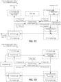
- FIGS. 1A-D illustrate schematic diagrams of fluid handling systems 100A-D including hydraulic energy transfer systems 110 (e.g., pressure exchangers), according to certain embodiments.
- hydraulic energy transfer systems 110 e.g., pressure exchangers
- Each hydraulic energy transfer system 110 of FIGS. 1A-D may include a pressure exchanger that includes a rotor configured to exchange pressure between a first fluid at a first pressure and a second fluid at a second pressure.
- the rotor forms ducts that are routed from a first distal end to a second distal end.
- the pressure exchanger further includes a first end cover that forms a high pressure in (HPIN) port configured to provide the first fluid at the first pressure into the ducts.
- the first end cover forms a low pressure out (LPOUT) port configured to receive the first fluid from the ducts at a third pressure.
- the pressure exchanger further includes a second end cover that forms a low pressure in (LPIN) port configured to provide the second fluid at the second pressure into the ducts and forms a high pressure out (HPOUT) port configured to receive the second fluid from the ducts at a fourth pressure.
- LPIN low pressure in
- HPOUT high pressure out
- the hydraulic energy transfer system 110 of FIGS. 1A-D has a HPIN port that is configured to provide the first fluid at the first pressure in a substantially axial direction into the ducts of the rotor of the hydraulic energy transfer system 110.
- one or more sidewalls (e.g., radial sidewalls) of the end cover that form the HPIN port or the LPOUT port are substantially planar (e.g., not curved).
- the second end cover forms a first spot face proximate the LPIN port and a second spot face proximate the HPOUT port.
- FIG. 1A illustrates a schematic diagram of a fluid handling system 100A including a hydraulic energy transfer system 110, according to certain embodiments.
- a hydraulic energy transfer system 110 includes a pressure exchanger (PX).
- the hydraulic energy transfer system 110 receives low pressure (LP) fluid in 120 (e.g., low-pressure inlet stream, low pressure in (LPIN)) from a LP in system 122.
- the hydraulic energy transfer system 110 also receives high pressure (HP) fluid in 130 (e.g., high-pressure inlet stream, high pressure in (HPIN)) from HP in system 132.
- LP low pressure
- HP high pressure
- the hydraulic energy transfer system 110 exchanges pressure between the HP fluid in 130 and the LP fluid in 120 to provide LP fluid out 140 (e.g., low-pressure outlet stream, low pressure out (LPOUT)) to LP fluid out system 142 and to provide HP fluid out 150 (e.g., high-pressure outlet stream, high pressure out (HPOUT)) to HP fluid out system 152.
- LP fluid out 140 e.g., low-pressure outlet stream, low pressure out (LPOUT)
- HP fluid out 150 e.g., high-pressure outlet stream, high pressure out (HPOUT)
- the hydraulic energy transfer system 110 includes a PX to exchange pressure between the HP fluid in 130 and the LP fluid in 120.
- the PX may be referred to as an isobaric pressure exchanger (IPX).
- IPX isobaric pressure exchanger
- the PX (e.g., an IPX) may be a device that transfers fluid pressure between HP fluid in 130 and LP fluid in 120 at efficiencies in excess of approximately 50%, 60%, 70%, 80%, 90%, or greater (e.g., without utilizing centrifugal technology, substantially isobaric pressure exchange).
- High pressure e.g., HP fluid in 130, HP fluid out 150 refers to pressures greater than the low pressure (e.g., LP fluid in 120, LP fluid out 140).
- Fluid handling system 100B may be a fracing system (e.g., hydraulic fracturing system). In some embodiments, fluid handling system 100B includes more components, less components, same routing, different routing, and/or the like than that shown in FIG. 1B .
- LP fluid in 120, HP fluid out 150, and low pressure fluid pumps 124 are part of a second loop (e.g., proppant containing fluid loop).
- the HP fluid out 150 may be provided into the rock formation 154 and then pumped from the rock formation 154 by the low pressure fluid pumps 124 to generate LP fluid in 120.
- fluid handling system 100B is used in well completion operations in the oil and gas industry to perform hydraulic fracturing (e.g., fracking, fracing) to increase the release of oil and gas in rock formations 154.
- HP out system 152 may include rock formations 154 (e.g., a well).
- Hydraulic fracturing may include pumping HP fluid out 150 containing a combination of water, chemicals, and solid particles (e.g., sand, ceramics, proppant) into a well (e.g., rock formation 154) at high pressures.
- LP fluid in 120 and HP fluid out 150 may include a particulate laden fluid that increases the release of oil and gas in rock formations 154 by propagating and increasing the size of cracks 156 in the rock formations 154.
- the high pressures of HP fluid out 150 initiates and increases size of cracks 156 and propagation through the rock formation 154 to release more oil and gas, while the solid particles (e.g., powders, debris, etc.) enter the cracks 156 to keep the cracks 156 open (e.g., prevent the cracks 156 from closing once HP fluid out 150 is depressurized).
- the hydraulic energy transfer system 110 blocks or limits wear on the high pressure fluid pumps 134, while enabling the fluid handling system 100B to pump a high-pressure frac fluid (e.g., HP fluid out 150) into the rock formation 154 to release oil and gas.
- a high-pressure frac fluid e.g., HP fluid out 150
- the hydraulic energy transfer system 110 may be made from materials resistant to corrosive and abrasive substances in either the first and second fluids.
- the hydraulic energy transfer system 110 may be made out of ceramics (e.g., alumina, cermets, such as carbide, oxide, nitride, or boride hard phases) within a metal matrix (e.g., Co, Cr or Ni or any combination thereof) such as tungsten carbide in a matrix of CoCr, Ni, NiCr or Co.
- ceramics e.g., alumina, cermets, such as carbide, oxide, nitride, or boride hard phases
- a metal matrix e.g., Co, Cr or Ni or any combination thereof
- tungsten carbide in a matrix of CoCr, Ni, NiCr or Co.
- FIG. 1C illustrates a schematic diagram of a fluid handling system 100C including a hydraulic energy transfer system 110, according to certain embodiments.
- Fluid handling system 100C may be a desalination system (e.g., remove salt and/or other minerals from water).
- fluid handling system 100C includes more components, less components, same routing, different routing, and/or the like than that shown in FIG. 1C .
- the membranes 136 may be a membrane separation device configured to separate fluids traversing a membrane, such as a reverse osmosis membrane.
- Membranes 136 may provide HP fluid in 130 which is a concentrated feed-water or concentrate (e.g., brine) to the hydraulic energy transfer system 110.
- Pressure of the HP fluid in 130 may be used to compress low-pressure feed water (e.g., LP fluid in 120) to be high pressure feed water (e.g., HP fluid out 150).
- feed water is used.
- fluids other than water may be used in the hydraulic energy transfer system 110.
- the hydraulic energy transfer system 110 can also be used for other applications, such as industrial waste water.
- the circulation pump 158 (e.g., centrifugal pump) provides the HP fluid out 150 (e.g., high pressure seawater) to membranes 136.
- the membranes 136 filter the HP fluid out 150 to provide LP potable water 172 and HP fluid in 130 (e.g., high pressure brine).
- the LP out system 142 provides brine out 174 (e.g., to geological mass, ocean, sea, discarded, etc.).
- a high pressure fluid pump 176 is disposed between the feed pump 126 and the membranes 136.
- the high pressure fluid pump 176 increases pressure of the low pressure seawater (e.g., LP fluid in 120, provides high pressure feed water) to be mixed with the high pressure seawater provided by circulation pump 158.
- use of the hydraulic energy transfer system 110 decreases the load on high pressure fluid pump 176.
- fluid handling system 100C provides LP potable water 172 without use of high pressure fluid pump 176.
- fluid handling system 100C provides LP potable water 172 with intermittent use of high pressure fluid pump 176.
- hydraulic energy transfer system 110 receives LP fluid in 120 (e.g., low-pressure feed-water) at about 30 pounds per square inch (PSI) and receives HP fluid in 130 (e.g., high-pressure brine or concentrate) at about 980 PSI.
- the hydraulic energy transfer system 110 e.g., PX
- transfers pressure from the high-pressure concentrate e.g., HP fluid in 130
- the low-pressure feed-water e.g., LP fluid in 120.
- the hydraulic energy transfer system 110 (e.g., PX) outputs HP fluid out 150 (e.g., high pressure (compressed) feed-water) at about 965 PSI and LP fluid out 140 (e.g., low-pressure concentrate) at about 15 PSI.
- HP fluid out 150 e.g., high pressure (compressed) feed-water
- LP fluid out 140 e.g., low-pressure concentrate
- the hydraulic energy transfer system 110 may be about 97% efficient since the input volume is about equal to the output volume of the hydraulic energy transfer system 110 (e.g., PX), and 965 PSI is about 97% of 980 PSI.
- FIG. 1D illustrates a schematic diagram of a fluid handling system 100D including a hydraulic energy transfer system 110, according to certain embodiments.
- Fluid handling system 100D may be a refrigeration system.
- fluid handling system 100D includes more components, less components, same routing, different routing, and/or the like than that shown in FIG. 1D .
- Hydraulic energy transfer system 110 may receive LP fluid in 120 from LP in system 122 (e.g., low pressure lift device 128, low pressure fluid pump, etc.) and HP fluid in 130 from HP in system 132 (e.g., condenser 138).
- the hydraulic energy transfer system 110 (e.g., PX) may exchange pressure between the LP fluid in 120 and HP fluid in 130 to provide HP fluid out 150 to HP out system 152 (e.g., high pressure lift device 159) and to provide LP fluid out 140 to LP out system 142 (e.g., evaporator 144).
- the evaporator 144 may provide the fluid to compressor 178 and low pressure lift device 128.
- the condenser 138 may receive fluid from compressor 178 and high pressure lift device 159.
- the fluid handling system 100D may be a closed system.
- LP fluid in 120, HP fluid in 130, LP fluid out 140, and HP fluid out 150 may all be a fluid (e.g., refrigerant) that is circulated in the closed system of fluid handling system 100D.
- the fluid of fluid handling system 100D may include solid particles.
- the piping, equipment, connections e.g., pipe welds, pipe soldering), etc. may introduce solid particles (e.g., solid particles from the welds) into the fluid in the fluid handling system 100D.
- the solid particles in the fluid and/or the high pressure of the fluid may cause abrasion and/or erosion of components (e.g., rotor, end covers) of the PX of hydraulic energy transfer system 110.
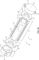
- FIGS. 2A-E are exploded perspective views a rotary PX 40 (e.g., rotary pressure exchanger, rotary liquid piston compressor (LPC)), according to certain embodiments.
- a rotary PX 40 e.g., rotary pressure exchanger, rotary liquid piston compressor (LPC)
- LPC liquid piston compressor
- PX 40 includes a rotor 46 configured to exchange pressure between a first fluid at a first pressure and a second fluid at a second pressure.
- the rotor 46 forms channels 70 (e.g., ducts) that are routed from a first distal end (e.g., opening 72) to a second distal end (e.g., opening 74).
- the PX 40 further includes an end cover 64 that forms a HPIN port (e.g., outlet aperture 76) configured to provide the first fluid at the first pressure into the channels 70.
- the end cover 64 forms a LPOUT port (e.g., outlet aperture 78) configured to receive the first fluid from the channels 70 at a third pressure.
- the PX 40 further includes an end cover 66 that forms a LPIN port (e.g., outlet aperture 80) configured to provide the second fluid at the second pressure into the channels 70 and forms a HPOUT port (e.g., outlet aperture 82) configured to receive the second fluid from the channels 70 at a fourth pressure.
- a LPIN port e.g., outlet aperture 80
- HPOUT port e.g., outlet aperture 82
- the PX 40 of FIGS. 2A-E has a HPIN port (e.g., outlet aperture 76) that is configured to provide the first fluid at the first pressure in a substantially axial direction into the channels 70 of the rotor 46 of the PX 40.
- a HPIN port e.g., outlet aperture 76
- one or more sidewalls (e.g., radial sidewalls) of the end cover 64 that form the HPIN port (e.g., outlet aperture 76) or the LPOUT port are substantially planar (e.g., not curved).
- the end cover 66 forms a first spot face proximate the LPIN port (e.g., outlet aperture 80) and a second spot face proximate the HPOUT port (e.g., outlet aperture 82).
- the PX 40 is configured to transfer pressure and/or work between a first fluid (e.g., proppant free fluid or supercritical carbon dioxide, HP fluid in 130) and a second fluid (e.g., frac fluid or superheated gaseous carbon dioxide, LP fluid in 120) with minimal mixing of the fluids.
- the rotary PX 40 may include a generally cylindrical body portion 42 that includes a sleeve 44 (e.g., rotor sleeve) and a rotor 46.
- the rotary PX 40 may also include two end caps 48 and 50 that include manifolds 52 and 54, respectively.
- Manifold 52 includes respective inlet port 56 and outlet port 58
- manifold 54 includes respective inlet port 60 and outlet port 62.
- these inlet ports 56, 60 enable the first and second fluids to enter the rotary PX 40 to exchange pressure, while the outlet ports 58, 62 enable the first and second fluids to then exit the rotary PX 40.
- the inlet port 56 may receive a high-pressure first fluid (e.g., HP fluid in 130), and after exchanging pressure, the outlet port 58 may be used to route a low-pressure first fluid (e.g., LP fluid out 140) out of the rotary PX 40.
- the inlet port 60 may receive a low-pressure second fluid (e.g., LP fluid in 120) and the outlet port 62 may be used to route a high-pressure second fluid (e.g., HP fluid out 150) out of the rotary PX 40.
- the end caps 48 and 50 include respective end covers 64 and 66 (e.g., end plates) disposed within respective manifolds 52 and 54 that enable fluid sealing contact with the rotor 46.
- one or more components of the PX 40 may be constructed from a wear-resistant material (e.g., carbide, cemented carbide, silicon carbide, tungsten carbide, etc.) with a hardness greater than a predetermined threshold (e.g., a Vickers hardness number that is at least 1000, 1250, 1500, 1750, 2000, 2250, or more).
- a predetermined threshold e.g., a Vickers hardness number that is at least 1000, 1250, 1500, 1750, 2000, 2250, or more.
- tungsten carbide may be more durable and may provide improved wear resistance to abrasive fluids as compared to other materials, such as alumina ceramics.
- the rotor 46 may be cylindrical and disposed in the sleeve 44, which enables the rotor 46 to rotate about the axis 68.
- the rotor 46 may have a plurality of channels 70 (e.g., ducts, rotor ducts) extending substantially longitudinally through the rotor 46 with openings 72 and 74 (e.g., rotor ports) at each end arranged symmetrically about the longitudinal axis 68.
- the openings 72 and 74 of the rotor 46 are arranged for hydraulic communication with inlet and outlet apertures 76 and 78 (e.g., end cover inlet port and end cover outlet port) and 80 and 82 (e.g., end cover inlet port and end cover outlet port) in the end covers 64 and 66, in such a manner that during rotation the channels 70 are exposed to fluid at high-pressure and fluid at low-pressure.
- the inlet and outlet apertures 76 and 78 and 80 and 82 may be designed in the form of arcs or segments of a circle (e.g., C-shaped).
- a controller using sensor feedback may control the extent of mixing between the first and second fluids in the rotary PX 40, which may be used to improve the operability of the fluid handling system (e.g., fluid handling systems 100A-D of FIGS. 1A-D ).
- the fluid handling system e.g., fluid handling systems 100A-D of FIGS. 1A-D .
- varying the volume flow rates of the first and second fluids entering the rotary PX 40 allows the plant operator (e.g., system operator) to control the amount of fluid mixing within the PX 40.
- varying the rotational speed of the rotor 46 also allows the operator to control mixing.
- the rotary PX 40 Three characteristics of the rotary PX 40 that affect mixing are: (1) the aspect ratio of the rotor channels 70; (2) the duration of exposure between the first and second fluids; and (3) the creation of a fluid barrier (e.g., an interface) between the first and second fluids within the rotor channels 70.
- the rotor channels 70 e.g., ducts
- the first and second fluids may move through the channels 70 in a plug flow regime with minimal axial mixing.
- the speed of the rotor 46 reduces contact between the first and second fluids.
- the speed of the rotor 46 may reduce contact times between the first and second fluids to less than approximately 0.15 seconds, 0.10 seconds, or 0.05 seconds.
- a small portion of the rotor channel 70 is used for the exchange of pressure between the first and second fluids. Therefore, a volume of fluid remains in the channel 70 as a barrier between the first and second fluids. All these mechanisms may limit mixing within the rotary PX 40.
- the rotary PX 40 may be designed to operate with internal pistons or other barriers, either complete or partial, that isolate the first and second fluids while enabling pressure transfer.
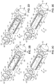
- FIGS. 2B-2E are exploded views of an embodiment of the rotary PX 40 illustrating the sequence of positions of a single rotor channel 70 in the rotor 46 as the channel 70 rotates through a complete cycle. It is noted that FIGS. 2B-2E are simplifications of the rotary PX 40 showing one rotor channel 70, and the channel 70 is shown as having a circular cross-sectional shape. In other embodiments, the rotary PX 40 may include a plurality of channels 70 with the same or different cross-sectional shapes (e.g., circular, oval, square, rectangular, polygonal, etc.). Thus, FIGS.
- the rotary PX 40 facilitates pressure exchange between first and second fluids by enabling the first and second fluids to briefly contact each other within the rotor 46. In certain embodiments, this exchange happens at speeds that result in limited mixing of the first and second fluids.
- FIG. 2B is an exploded perspective view of an embodiment of a rotary PX 40 (e.g., rotary LPC), according to certain embodiments.
- the channel opening 72 is in a first position. In the first position, the channel opening 72 is in fluid communication with the aperture 78 in end cover 64 and therefore with the manifold 52, while the opposing channel opening 74 is in hydraulic communication with the aperture 82 in end cover 66 and by extension with the manifold 54.
- the rotor 46 may rotate in the clockwise direction indicated by arrow 84.
- low-pressure second fluid 86 passes through end cover 66 and enters the channel 70, where it contacts the first fluid 88 at a dynamic fluid interface 90.
- the second fluid 86 then drives the first fluid 88 out of the channel 70, through end cover 64, and out of the rotary PX 40.
- FIG. 2C is an exploded perspective view of an embodiment of a rotary PX 40 (e.g., rotary LPC), according to certain embodiments.
- the channel 70 has rotated clockwise through an arc of approximately 90 degrees.
- the opening 74 e.g., outlet
- the opening 72 is no longer in fluid communication with the apertures 76 and 78 of end cover 64. Accordingly, the low-pressure second fluid 86 is temporarily contained within the channel 70.
- FIG. 2D is an exploded perspective view of an embodiment of a rotary PX 40 (e.g., rotary LPC), according to certain embodiments.
- the channel 70 has rotated through approximately 60 degrees of arc from the position shown in FIG. 2B .
- the opening 74 is now in fluid communication with aperture 80 in end cover 66, and the opening 72 of the channel 70 is now in fluid communication with aperture 76 of the end cover 64.
- high-pressure first fluid 88 enters and pressurizes the low-pressure second fluid 86, driving the second fluid 86 out of the rotor channel 70 and through the aperture 80.
- FIG. 2E is an exploded perspective view of an embodiment of a rotary PX 40 (e.g., rotary LPC), according to certain embodiments.
- the channel 70 has rotated through approximately 270 degrees of arc from the position shown in FIG. 2B .
- the opening 74 is no longer in fluid communication with the apertures 80 and 82 of end cover 66
- the opening 72 is no longer in fluid communication with the apertures 76 and 78 of end cover 64.
- the first fluid 88 is no longer pressurized and is temporarily contained within the channel 70 until the rotor 46 rotates another 90 degrees, starting the cycle over again.
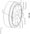
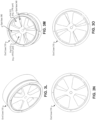
- FIGS. 3A-P illustrate components of pressure exchangers 300 (e.g., PXs 40 of FIGS. 2A-E ), according to certain embodiments.
- FIGS. 3A-P that have similar names and/or reference numbers as features in one or more of FIGS. 1A-2E may include the same or similar structure, material, functionality, and/or the like as features in one or more of FIGS. 1A-2E .
- one or more features of PX 300 of FIGS. 3A-P reduce mixing of fluids in the PX 300.
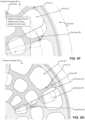
- FIG. 3A illustrates a perspective view of an end cover 310 (e.g., end cover 64 and/or 66 of one or more of FIGS. 2A-E ).
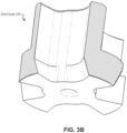
- FIG. 3B illustrates a perspective cut-away view of an end cover 310 (e.g., of FIG. 3A , end cover 64 and/or end cover 66 of one or more of FIGS. 2A-E ).
- FIG. 3C illustrates a cross-sectional view of components of the pressure exchanger 300 (e.g., of FIG. 3A and/or 3B, end cover 64 and/or 66 of one or more of FIGS. 2A-E , rotor 46 of one or more of FIGS. 2A-E ).
- a PX 300 includes a rotor 320 and end covers 310.
- the rotor 320 is configured to rotate to exchange pressure between a first fluid at a first pressure and a second fluid at a second pressure.
- the rotor 320 forms ducts 322 (e.g., channel 70 of FIGS. 2A-E ) that are routed from a first distal end of the rotor 320 to a second distal end of the rotor 320.
- the PX 300 may include first and second end covers 310.
- the first end cover 310 is disposed at the first distal end of the rotor 320 and the second end cover 310 is disposed at the second distal end of the rotor 320.
- End cover 310 is disposed at a distal end of the rotor 320. End cover 310 forms ports 312 (e.g., apertures 76 and 78 of FIGS. 2A-E , apertures 80 and 82 of FIGS. 2A-E , inlet, outlet, HPIN port, HPOUT port, LP IN port, LPOUT port)
- ports 312 e.g., apertures 76 and 78 of FIGS. 2A-E , apertures 80 and 82 of FIGS. 2A-E , inlet, outlet, HPIN port, HPOUT port, LP IN port, LPOUT port
- end cover 310 (e.g., disposed at a first distal end of the rotor 320) forms an HPIN port configured to provide the first fluid at the first pressure in a substantially axial direction into the ducts 322 and an LPOUT port configured to receive the first fluid from the ducts 322 at a third pressure that is lower than the first pressure.
- end cover 310 (e.g., disposed at a second distal end of the rotor 320) forms an LPIN port configured to provide the second fluid at the second pressure into the ducts 322 and forms an HPOUT port configured to receive the second fluid from the ducts 322 at a fourth pressure that is higher than the second pressure.
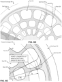
- PX 300 may include two ramps to reduced rotor incidence losses and to prevent skewing of the interface.
- end cover insert 330 e.g., made of polycarbonate, fiber reinforced polytetrafluoroethylene (PTFE) and/or polyetheretherketone (PEEK) to guide the flow.
- PTFE fiber reinforced polytetrafluoroethylene
- PEEK polyetheretherketone
- end cover 310 has 3D ramps.
- end cover 310 has an HPIN kidney closure earlier than HPOUT by at least 2 degrees to avoid acceleration of flow as duct closes.
- end cover 310 has a fillet (e.g., large fillet) at HPIN kidney exit diameter corner (e.g., to reduce mixing through inner row of ducts).
- a fillet e.g., large fillet
- HPIN kidney exit diameter corner e.g., to reduce mixing through inner row of ducts.
- PX 300 has HPIN kidney opening later than HPOUT to help move interface away from HPOUT and to reduce mixing at HPOUT.
- spot faces are located at HPOUT open (and not on HPIN open) to reduce mixing at HPOUT and to avoid disturbing the interface which is close to HPIN open.
- HPOUT fluid is used as bearing fluid and center bore fluid (e.g., to reduce mixing of HPIN to HPOUT through leakage in axial gaps).
- length to depth (L/D) ratio and roundness of ducts 322 are maximized.
- honeycomb flow straighteners are used as inserts in the ducts 322 to reduce mixing.
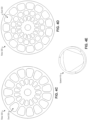
- an end cover 310 includes radial sidewalls 314 (e.g., leading radial sidewall 314A, trailing radial sidewall 314B), an inner sidewall 316, and an outer sidewall 318 that form a port 312 (e.g., HPIN port, HPOUT port, LPIN port, LPOUT).
- Leading radial sidewall 314A is the first radial sidewall that a duct 322 sees as it rotates.
- the trailing radial sidewall 314B is the sidewall of the same port that the rotor duct 322 sees after the leading radial side wall.
- ports 312 have similar sizes.
- the radial sidewalls 314 of the HPIN port are at least two degrees (e.g., four degrees, six degrees, eight degrees, ten degrees, etc.) closer to each other that radial sidewalls 314 of the HPOUT port are to each other (e.g., see FIGS. 3G-H ).
- FIG. 3G may be an HPOUT port and FIG. 3H may be an HPIN port.
- At least one of the radial sidewalls 314 (e.g., trailing radial sidewall) that form the HPIN port is configured to close relative to a duct 322 formed by the rotor 320 at least two degrees (e.g., four degrees, six degrees, eight degrees, ten degrees, etc.) prior to at least one of the second radial sidewalls (e.g., trailing radial sidewall) that form the HPOUT port closes relative to the duct 322 (e.g., to reduce mixing of corresponding fluid between HPIN and HPOUT, reduce mixing of HPIN into HPOUT).
- At least one of the radial sidewalls 314 (e.g., trailing radial sidewall) that form the LPIN port is configured to close relative to a duct 322 formed by the rotor 320 at least two degrees (e.g., four degrees, six degrees, eight degrees, ten degrees, etc.) prior to at least one of the second radial sidewalls (e.g., trailing radial sidewall) that form the LPOUT port closes relative to the duct 322 (e.g., to reduce mixing of corresponding fluid between LPIN and LPOUT, reduce mixing of LPIN into LPOUT).
- one or more radial sidewalls of the LPOUT port are biased to reduce mixing at the LPOUT port.
- each of the radial sidewalls 314 that form the HPIN port have a substantially straight edge that substantially matches a corresponding substantially straight edge of a duct 322 formed by the rotor 320 (e.g., to maximize the time of duct 322 exposure to the port to improve efficiency).
- a first end cover 310 forms a first port and a second port, where a first substantially straight radial edge of the first port and a second substantially straight radial edge of the second port substantially match corresponding substantially straight edges of the ducts 322 of the rotor 320.
- a second end cover 310 forms a third port and a fourth port, where a third substantially straight radial edge of the third port and a fourth substantially straight radial edge of the fourth port substantially match the corresponding substantially straight edges of the ducts 322 of the rotor 320.
- At least one of the radial sidewalls 314 (e.g., leading radial sidewall) that form the HPIN port is configured to open relative to a duct 322 formed by the rotor 320 at least two degrees (e.g., four degrees, six degrees, eight degrees, ten degrees, etc.) later than at least one of the second radial sidewalls (e.g., leading radial sidewall) that form the HPOUT port opens relative to the duct 322.
- an end cover 310 (e.g., that forms HPIN port) forms a fillet (or filet) (e.g., concave strip of material roughly triangular in cross section that rounds off an interior angle between two surfaces) between at least one of the radial sidewalls 314 and an inner sidewall 316.
- the end cover 310 that forms the HPOUT port may form the HPOUT port without a fillet between the radial sidewalls 314 and the inner sidewall 316.
- the fillet of the end cover 310 (e.g., that forms HPIN port) is configured to close the HPIN port relative to a duct 322 of the rotor 320 prior to the HPOUT port of the end cover that forms HPOUT port closes relative to the duct 322.
- the fillet may be located at HPIN port exit inner diameter corner.
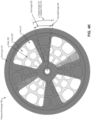
- the rotor 320 may form multiple circular rows of ducts 322 with outer rows being approximately trapezoidal in shape and the inner most row being triangular in shape. Due to the reduction in roundness from outer ducts to inner ducts, the inner most row of triangular shaped ducts may contribute more to mixing at HPOUT (per unit flow area) than ducts in the outer rows. By increasing the filet radius at the inner diameter exit corner of the HPOUT port, mixing contribution from inner ducts may be reduced.
- a fillet at HPIN port bottom corner results in reduction of fluid (e.g., brine concentration, the fluid with which pressure is being exchanged) exiting out of the HPOUT row from the inner row of ducts 322.
- the radial sidewalls 314 of the end cover 310 each form a ramp (e.g., sloped sidewall, sidewall that is not perpendicular to the face of the end cover) (e.g., see FIGS. 3A-E ) and the radial sidewalls 314 of the other end cover forms HPIN port (e.g., and LPOUT port) without forming ramps.
- a ramp e.g., sloped sidewall, sidewall that is not perpendicular to the face of the end cover
- HPIN port e.g., and LPOUT port
- the radial sidewalls 314 of the end cover 310 each form a ramp (e.g., sloped sidewall, sidewall that is not perpendicular to the face of the end cover) (e.g., see FIGS. 3A-E ) and the radial sidewalls 314 of the other end cover forms HPIN port (e.g., and LPOUT port) each form a ramp.
- a ramp e.g., sloped sidewall, sidewall that is not perpendicular to the face of the end cover
- HPIN port e.g., and LPOUT port
- the first radial sidewalls include a leading sidewall and a trailing sidewall on the HPIN port that each have a corresponding ramp angle varying from about 30 degrees to about 70 degrees measured with respect to a face of the rotor 320.
- leading radial sidewall and trailing radial sidewall on the LPIN port form a ramp in direction of rotation.
- the ramp has a ramp angle varying from about 30 degrees to about 70 degrees measured with respect to a face of the rotor 320.
- the radial sidewalls 314 of the end cover 310 form non-planar three-dimensional ramps (e.g., see ramps 317A-B of FIG. 3E ).
- the first radial sidewalls form non-planar three-dimensional ramps defined by at least two helix at an innermost radius and outermost radius of the port.
- a corresponding ramp of the non-planar three-dimensional ramps is defined by a spiral that has a pitch that is proportional to a radius at which the corresponding ramp is located to reduce incidence (e.g., to reduce incidence and to cause absolute velocity (c) to be similar at any radius of the port).
- the ramps 317 may be associated with velocity triangle 319.
- Flow exiting the rotor 320 of a PX 300 may have a combination of axial and tangential components of flow velocity.
- the axial component is a function of flow rate and the tangential component is a function of rotor speed and radial position of the duct 322.
- the outlet kidneys e.g., port 312 of end cover 310) are shaped to allow for smooth transition of this three-dimensional (3D) velocity field from the rotor 320 to a one-dimensional (1D) velocity field along the stator conduits (e.g., ports 312 of end cover 310). Otherwise, shock losses may result due to flow separation and eddy formation in the outlet kidneys (e.g., ports 312 of end cover 310).
- the exit ramps can have a single ramp angle based on the design flow rate, target RPM, a median radial position of the duct 322, and/or the like.
- the outlet kidneys e.g., ports 312 of end cover 310) can also have dual ramps at the beginning and end of the outlet kidneys with similar considerations.
- a 3D-shaped outlet kidney e.g., port 312 of end cover 310) may have a ramp angle that varies continually with the radial position.
- an injection molded plastic insert with a particular shape can be embedded into the outlet kidneys (e.g., port 312 of end cover 310).
- the end cover 310 includes an insert 330 disposed in the HPIN port, where the insert is configured to guide flow and to reduce flow incidence at the rotor 320 (e.g., see FIG. 3F ).
- the end cover 310 forms a first spot face 340 proximate the HPIN port (e.g., without forming a spot face at the HPIN port to reduce mixing of corresponding fluid between the HPIN port and the HPOUT port) and forms a second spot face 340 proximate the LPOUT port (e.g., see FIGS. 3L-O ).
- the first end cover 310 forms a second spot face proximate the LPOUT port without forming a spot face at the LPIN port to reduce mixing of corresponding fluid between the LPIN port and the LPOUT port.
- the pressure exchanger 300 (e.g., PX 40) is configured to use the second fluid provided via the LPIN port and/or HPOUT port as bearing fluid and/or centerbore fluid (e.g., see FIGS. 3I-K ).
- FIG. 3P illustrates PX 300, according to certain embodiments.
- Rotor 320 may include inserts 330 disposed in ducts 322.
- the inserts may provide a length to diameter ratio of about 5 to about 10.
- the inserts may be honeycomb-shaped inserts.
- the inserts may be honeycomb-shaped flow straighteners that are press-fit or shrunk-fit into the ducts.
- the inserts 330 may maximize the length to diameter (L/D) ratio and the roundness of ducts 322.
- the inserts 330 may be honeycomb flow straighteners in the ducts 322 to reduce mixing of fluids.
- Turbulence of unsteady fluid flow in the ducts 322 may cause (e.g., may be a major source of) intra-duct mixing. This results in skewing & stretching of the "mixing zone" between the two fluids in the duct 322.
- the aspect ratio of duct geometry e.g., length to diameter - L/D
- inserts 330 e.g., honeycomb flow straighteners
- the flow straighteners can be press-fit or shrunk-fit into the ducts 322 or attached to the duct walls mechanically or adhesively (e.g., gluing).
- the insert 330 (e.g., flow straightener) can have shapes other than honeycomb and the insert 330 may divide a duct of a certain LID ratio into multiple ducts of larger LID ratio. Breaking a duct into multiple small ducts also reduces cavitation and noise by temporally spreading out pressurization and depressurization events at kidney openings (e.g., openings of ports 312 of end covers 310).
- pressure exchanger 300 is used to minimize mixing of two fluids inside the pressure exchanger 300.
- liquid-to-liquid pressure exchange may take place via an oscillating "liquid plug" in the rotor ducts.
- the "liquid plug” may not be impenetrable and conventionally a small amount of mixing may occur between the two fluids exchanging their pressure energy. Mixing may be dependent on one or more factors, such as travel distance of the "liquid plug” (e.g., portion of the duct 322 of the rotor 320 traverses), turbulence, diffusion, jetting, entry and/or exit losses of the rotor 320, etc.
- Efficiency of the pressure exchanger 300 may be directly proportional to the travel distance of the "liquid plug.” Mixing of a first fluid and a second fluid in the pressure exchanger 300 may be inversely proposal to the travel distance (and to the efficiency in the pressure exchanger 300). In some examples, less travel distance results in less mixing and lower efficiency. In some examples, more travel distance results in more mixing and higher efficiency (e.g., features that attempt to increase efficiency by increasing travel distance conventionally also increase mixing within the pressure exchanger). In some applications (e.g., a SWRO plant), efficiency of a pressure exchanger 300 is to be maximized and mixing within the pressure exchanger 300 is to be minimized to reduce specific energy consumption (e.g., of the SWRO plant).
- Pressure exchanger 300 may include one or more features configured to reduce mixing within the pressure exchanger 300 without having a negative impact on efficiency of the pressure exchanger 300 (e.g., minimizing decrease in efficiency, maintaining efficiency, increasing efficiency compared to pressure exchangers that do not have those features).
- pressure exchanger 300 may provide reduced rotor incidence losses (e.g., two ramps at entrance of port 312 to reduce incidence). Incidence may be an angle between ideal c velocity vector and actual c velocity vector.
- the axial component may remain constant at any axial plane of the rotor 320, whereas the tangential component varies linearly with the radial coordinate.
- End cover 310 forms ports 312 configured to guide the flow for a given nominal flow rate and a target RPM of rotor 320 that results in substantial reduction in mixing and reduction in pressure loss due to sudden change in flow direction.
- end cover 310 includes two ramps (e.g., a ramp at each radial sidewall 314) to provide substantial tangential flow velocity component in addition to the axial flow velocity component.
- the end cover 310 has 3D ramps (e.g., further kidney geometry optimization) to provide smooth entry of fluid from port 312 to ducts 322 (e.g., see right side of FIG. 3C )
- an insert 330 may be embedded into the port 312 (e.g., see FIG. 3F ).
- the insert 330 may be made of Alumina ceramic, plastics such as polycarbonate, fiber reinforced polytetrafluoroethylene (PTFE) and/or polyetheretherketone (PEEK), and/or the like.
- End cover 310 of FIG. 3H may reduce effective width of the port 312 (e.g., kidney) by opening HPIN port 312 a few degrees later than baseline and thus reduces efficiency.
- the port 312 e.g., kidney
- HPIN port may close earlier than HPOUT port (e.g., radial sidewalls 314 of HPIN port are closer to each other than radial sidewalls 314 of HPOUT). This may reduce mixing at HPOUT port caused by fluid inertia. Mixing at HPOUT port is undesirable when a pressure exchanger is used for energy recovery in particular applications (e.g., in an SWRO plant).
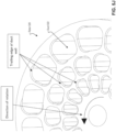
- the flow in the duct 322 of the rotor 320 accelerates as the duct 322 traverses across the HP ports. Average duct flow velocity starts from near-zero when the duct 322 opens to the HP ports and reaches a maximum just as it begins to exit the ports (e.g., kidneys).
- the mixing zone (e.g., "liquid plug") may have traveled the maximum extent through the duct and may be proximate (e.g., very close) to the HPOUT port. Jets into HPOUT port may transport fluid from the mixing zone as well as some HPIN fluid behind the mixing zone into the HPOUT port, increasing undesirable mixing at HPOUT port.
- the present disclosure may mitigate this mixing increase by closing the HPIN port a few degrees prior to the HPOUT port. This results in peak velocities being reached before the duct 322 closes to HPOUT port. Duct flow is decelerating when the fluid in the duct 322 exits the HPOUT port causing the pressure spike due to fluid inertia to decrease substantially. Jetting of mixing zone fluid into HPOUT port is greatly reduced, resulting in reduced mixing at HPOUT port.
- HPIN port may open later than HPOUT port. Delaying the HPIN port opening after the HPOUT port biases the mean location of the two-fluid interface closer to the HPIN port than the LPIN port. This helps move the interface away from HPOUT and reduces mixing of HPIN at HPOUT. This feature can be selectively utilized when reducing mixing is a higher priority and slight tradeoff in efficiency is acceptable. Delaying HPIN opening a few degrees with respect to HPOUT can move the interface away from HPOUT and this may reduce mixing at HPOUT.
- the kidney exit ramps (e.g., radial sidewalls 314) of the end covers 310 may be configured to guide flow into HPOUT and LPOUT ports while minimizing shock losses at exit (e.g., shock losses due to flow separation).
- Flow exiting ducts 322 of rotor 320 into outlet ports has both axial and tangential components of velocity.
- Axial velocity component may not vary much with radius, but tangential velocity component scales linearly with radius.
- Outlet port walls may be configured to provide duct flow smoothly exiting through the ports without any separation.
- the sidewalls of the end cover 310 that form the ports 312 may be configured to accommodate the varying ratio of tangential and axial components of velocity with radius.
- Spot faces 340 may be located to reduce mixing (e.g., see FIGS. 3L-O ). Spot faces 340 may be used on ports 312 to gradually pressurize or depressurize a duct 322 of a rotor 320 (e.g., instead of abrupt pressure equalization through high velocity jetting into or out of the rotor duct). Spot faces 340 reduce the jetting velocity due to pressure differential between the duct 322 and the port 312 by adding resistance to flow through the narrow gap. In some embodiments, the spot faces 340 are located on HPOUT port without being located in HPIN port. This may compensate for the depth of the spot face 340 and pressure equalization may be achieved by jets of HPOUT fluid entering the low-pressure rotor duct instead of HPIN fluid. The "liquid plug" may be farthest away from HPOUT port when the pressure equalization occurs and mixing is reduced.
- second fluid e.g., exiting HPOUT port, HPOUT fluid
- first fluid e.g., HPIN fluid
- second fluid e.g., HPOUT fluid
- bearing performance e.g., stiffness and load capacity
- HPOUT fluid may be used as the bearing fluid and may reduce mixing at HPOUT port.
- HPIN fluid may be isolated preventing the chance of increased mixing through leakage from the bearing gaps.
- HPOUT fluid may be used to feed pressure exchanger radial bearings and to fill the centerbore of the rotor (e.g., see FIGS. 3I-J ).
- PX 300 may include a fluid bypass 350 (e.g., HPOUT fluid bypass), according to certain embodiments.
- Fluid may enter between the housing 352 and end cover 310 (e.g., LPIN end cover) and flow between housing 352 and sleeve 301 and via an opening in sleeve 301 (e.g., to feed pressure exchanger radial bearings and/or to fill the center bore).
- fluid bypass 350 e.g., HPOUT fluid bypass
- a gasket e.g., O-ring
- PX 300 may include a fluid bypass 350 (e.g., HPOUT fluid bypass) and/or slot 354, according to certain embodiments.
- the fluid bypass 350 may be an HPOUT fluid bypass of gasket (e.g., O-ring) and may feed the PX radial bearings through a hole in the sleeve.
- Slot 354 in end cover 310 e.g., HPOUT end cover
- center bore 356 e.g., central portion of rotor 320, between rotor 320 and shaft.
- the length to diameter (L/D) ratio and the roundness of the ducts 322 are maximized.
- Mixing in a rotor duct may be a strong function of turbulence, the influence of which can be reduced significantly be controlling the LID ratio and the roundness of the ducts.
- Inserts may be added to the rotor 320 to achieve a desired duct shape, achieve near "liquid plug" flow, and reduce mixing in the rotor ducts.
- the present disclosure may be employed in rotary pressure exchangers to reduce mixing of the two fluids across which pressure energy is being exchanged.
- the present disclosure may include features such as ramps (e.g., kidney ramps), spot faces 340, filets, etc. (e.g., to reduce mixing).
- ramps e.g., kidney ramps
- spot faces 340 e.g., filets, etc. (e.g., to reduce mixing).
- the present disclosure reduces the mixing of fluids in a pressure exchanger and improves overall energy consumption per unit volume (e.g., of potable water produced in a SWRO plant).
- the present disclosure is applicable for different pressure exchanger (e.g., isobaric pressure exchanger) applications, such as SWRO, sCO2, industrial wastewater, etc.
- the present disclosure may also be applicable for pressure exchanger architectures, such as a PX with rotor-sleeve or sleeveless pressure exchanger (e.g., rotor with center-post) and motorized or non-motorized PX.
- the present disclosure can be applied appropriately for different applications to reduce mixing of LPIN into LPOUT as well.
- a pressure exchanger 300 includes a rotor 320 and end covers 310.
- the rotor 320 is configured to rotate to exchange pressure between a first fluid at a first pressure and a second fluid at a second pressure.
- the rotor 320 forms ducts 322 that are routed from a first distal end of the rotor 320 to a second distal end of the rotor 320.
- radial edge of kidney entrance and exits of end cover 310 may matching that of the rotor 320.
- non-metallic PVC spacer is used in PX 300 to handle axial thrust and to avoid fretting corrosion between ceramic end cover 310 and metallic interconnect.
- radial and axial bearing clearances are optimized for target circumference groove pressure.
- the ports of end cover 310 are maximized to be substantially the same size as one duct 322 plus one wall sealing area of rotor 320 to reduce difference in pressure (DP) losses.
- pressure loads are substantially balanced on both rotor faces of rotor 320.
- duct shape of ducts 322 substantially matches ports (e.g., kidneys) of end covers 310 (e.g., trapezoidal or triangular instead of circular).
- an end cover 310 (e.g., a first end cover) is disposed at a distal end (e.g., the first distal end) of the rotor 320 and the end cover 310 forms a HPIN port configured to provide the first fluid at the first pressure into the ducts 322 and forms a LPOUT port configured to receive the first fluid from the ducts 322 at a third pressure that is lower than the first pressure.
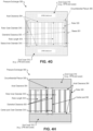
- One or more sidewalls (e.g., radial sidewalls 314) of the end cover that form the HPIN port and/or the LPOUT port are substantially planar (e.g., straight edge 401, not curved edge 402) (e.g., see FIG. 4B ).
- the one or more sidewalls of the first end cover 310 that form the HPIN port have a substantially straight edge 401 that substantially matches a corresponding substantially straight edge of a duct 322 formed by the rotor 320.
- an end cover 310 is disposed at a distal end (e.g., second distal end) of the rotor 320 and the end cover forms a LPIN port configured to provide the second fluid at the second pressure into the ducts 322 and forms a HPOUT port configured to receive the second fluid from the ducts 322 at a fourth pressure that is higher than the second pressure.
- the end cover 310 (e.g., that forms HPIN port and LPOUT port, that forms LPIN port and HPOUT port) includes substantially planar radial sidewalls 314 (e.g., non-curved radial sidewalls 314), an inner sidewall 316, and an outer sidewall 318 that form the port 312 (e.g., HPIN port, HPOUT port).
- the first substantially radial sidewalls 314 may be disposed between a center of the end cover 310 and a perimeter of the end cover 310.
- the inner sidewall 316 may be proximate the center of the end cover 310 and the outer sidewall 318 may be proximate the perimeter of the end cover 310.
- the rotor 320 may form ducts 322 in concentric rows (e.g., see FIGS. 4C-D ).
- a ratio of a number of the concentric rows to inches of diameter of the rotor 320 may be about 0.3 to about .45 (e.g., from about 0.375 to about 0.42).
- the rotor 320 may form the ducts 322 in at least three concentric rows.
- the pressure exchanger 300 may include a first interconnect 420 configured to provide the first fluid to the HPIN port of the end cover 310, a first spacer 410 (e.g., see FIG. 4E ) disposed in the end cover 310 between the first interconnect and the HPIN port (e.g., see FIG. 4F ).
- the pressure exchanger 300 may include a second interconnect 420 configured to receive the first fluid from the LPOUT port of the end cover 310 and a second spacer 410 disposed in the first end cover between the LPOUT port and the second interconnect (e.g., see FIG. 4F ).
- the first spacer and/or the second spacer are a thermoplastic material.
- the first spacer and/or the second spacer are polyvinyl chloride (PVC).
- FIGS. 4G-4H illustrate PXs 300, according to certain embodiments.
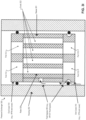
- a PX 300 may have bearing stiffness tuned to center the rotor 320 and to reduce leakage by optimizing diametral clearance 303 (e.g., radial clearance) and axial clearance 304 (e.g., axial bearing clearance, a height difference between the sleeve and the rotor or between the center post and the rotor) for target circumferential groove pressure.
- diametral clearance 303 e.g., radial clearance
- axial clearance 304 e.g., axial bearing clearance, a height difference between the sleeve and the rotor or between the center post and the rotor
- the rotor 320 is separated from the stator (e.g., end cover 310, sleeve 301) with a small clearance both radially (e.g., diametral clearance 303 between the sleeve 301 and rotor 320 or center post 302 and rotor 320) and axially (e.g., axial clearance 304 between end covers 310 and rotor 320).
- the stator e.g., end cover 310, sleeve 301
- axially e.g., axial clearance 304 between end covers 310 and rotor 320.
- the rotor 320 is to have minimal clearances and the rotor 320 is to be centered axially (e.g., with smallest axial eccentricity).
- Minimal clearances are set by manufacturing and material stiffness limitations.
- Minimal eccentricity can be achieved by maintaining the ratio between the diametral clearance 303 and axial clearance 304 within a narrow range of about 1 to about 3.5.
- Such an arrangement may provide an intermediate plenum pressure (e.g., the optimal intermediate plenum pressure) (e.g., in circumferential plenum 305) between the two bearings resulting in lower axial rotor eccentricity (e.g., lowest axial rotor eccentricity) and in so doing, minimize leakage loss.
- a ratio of diametral clearance 303 (e.g., diametric clearance, diametric clearance, radial clearance, etc.) to axial clearance 304 is about 1 to about 3.5.
- the diametral clearance 303 is between the rotor 320 and a sleeve 301 or between the rotor 320 and a center post 302.
- the axial clearance 304 is between the rotor 320 and an end cover 310.
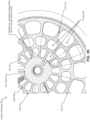
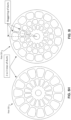
- FIG. 4I illustrates a rotor 320, according to certain embodiments.
- FIG. 4J illustrates an end cover 310 according to certain embodiments.
- FIG. 4K illustrates a PX 300 with rotor 320 superimposed on end cover 310, according to certain embodiments.
- sealing angle 313 between ports 312 of end cover 310 may be at least the same as the duct angle 323 plus duct wall angle 324 of rotor 320.
- angular spacing between the HPIN port and the LPOUT port of the first end cover 310 substantially matches corresponding angular spacing between a first leading radial sidewall of a first duct 322 of the rotor 320 and a second leading radial sidewall of a second duct 322 that is adjacent to the first duct 322.
- Fluid flow in the ducts of a rotary pressure exchanger may be unsteady with rapid acceleration and deceleration in both directions during each rotation. This results in a pressure loss across the rotor required to overcome fluid inertia. Apart from reducing rotor speed (which can result in increased mixing), this inertial pressure loss can also be minimized by maximizing the flow area of the kidneys (e.g., ports 312 of end cover 310). This results in lower acceleration for the same flow rate which provides a reduction in inertial pressure loss.
- a minimum amount of sealing angle of end cover 310 may be maintained substantially equivalent (e.g., equivalent) to the angular spacing between the ducts 322 (duct angle 323 plus duct wall angle 324).
- the present disclosure may optimize a pressure exchanger 300 (e.g., isobaric pressure exchanger) for efficiency, mixing, cavitation, sound, and cost.
- a pressure exchanger 300 e.g., isobaric pressure exchanger
- features that attempt to increase efficiency by increasing travel distance end up increasing mixing inside the pressure exchanger.
- the present disclosure may maximize efficiency at a similar travel distance as conventional pressure exchangers without having a negative impact on mixing performance (e.g., by maintaining the same amount of mixing, by decreasing mixing, etc.).
- the present disclosure may be used in different pressure exchanger (e.g., isobaric pressure exchanger) applications (e.g., using a pressure exchanger for energy recovery), such as SWRO, sCO2, industrial waste water, etc.
- pressure exchanger e.g., isobaric pressure exchanger
- the present disclosure may be used in different pressure exchanger architectures, such as a pressure exchanger with rotor-sleeve or sleeveless pressure exchanger (e.g., rotor with center-post) and motorized or non-motorized pressure exchanger.
- the present disclosure may be used to reduce fluid inertial pressure loss using radial edge of the port 312 (e.g., kidney) entrance and exits.
- a substantially amount of the pressure loss in the rotor 320 occurs due to sudden acceleration and deceleration of flow inside the rotor 320.
- the differential pressure to accelerate the flow inside the duct 322 of the rotor 320 e.g., pressure lost in accelerating the flow inside the rotor ducts in terms of dQ/dt
- Equation 1 can be re-written as Equation 2 (e.g., pressure lost in accelerating the flow inside the rotor ducts in terms of dQ/d ⁇ ).
- Equation 2 e.g., pressure lost in accelerating the flow inside the rotor ducts in terms of dQ/d ⁇ .
- ⁇ P fluid_inertia ⁇ fluid * L duct / A duct / ⁇ * dQ duct / d ⁇
- the dP fluid_inertia (e.g., ⁇ Pfizid_inertia ) can be decreased by reducing the dQ/d ⁇ term.
- end covers 310 of the present disclosure include substantially planar radial sidewalls 314 (e.g., radial-edge end covers 310).
- radial-edge port may cause an effective kidney angle for the middle and outer-most ducts to be increased as compared to curved-edge ports (e.g., by about 26% for outer-most duct).
- the radial edge of the port 312 may cause the trapezoidal shape of the port 312 to match the trapezoidal shape of ducts 322 of rotor 320.
- fluid inertial pressure loss may be reduced by maximizing rotor flow with selection of number and shape of rotor ducts.
- duct passage-ways help convey flow from the inlet to the outlet ports. Most amount of pressure losses may occur in the rotor 320.
- Increasing the rotor duct flow area may reduce pressure loss, without having a negative impact on mixing.
- the constraint may be that stress are to be below the material strength of the rotor 320.
- the rotor 320 has trapezoidal shaped ducts 322 with large fillets to make use of available area by maximizing duct flow area and preventing high stress concentrations (e.g., see FIG. 4D ).
- the number of concentric rows is selected to maximize the total duct flow area, while also minimizing the maximum duct area and meeting the strength criteria of the material. This also helps achieve effective hydraulic diameter similar to an equivalent circle (e.g., prevents high aspect ratio ducts).
- the rotor 320 has an odd number of ducts 322 (e.g., a non-even number of ducts). This prevents opening of a duct 322 to symmetrically opposite ports 312 at the same time which reduces noise and vibration of the pressure exchanger 300.
- the rotor 320 has staggered ducts which reduces the total amount of duct volume that pressurizes and/or depressurizes at a time which reduces noise and vibration of the pressure exchanger.
- the rotor 320 has at least two concentric rows of ducts 322. In some embodiments, the rotor 320 has at least three concentric rows of ducts 322.
- a spacer e.g., lofted spacer, streamlined spacer
- the LPOUT port is guided to minimize shock losses at exit due to flow separation.
- Flow exiting rotor ducts into outlet ports has both axial and tangential components of velocity.
- Axial velocity component may not vary much with radius of the rotor 320. Tangential component scales linearly with radius.
- Outlet port (e.g., LPOUT port, HPOUT port) walls may be designed so that the duct flow exits smoothly through the ports 312 without separation.
- the port sidewalls e.g., kidney walls
- the mixing zone may be closest to the duct exit at outlet ports (e.g., outlet kidneys) of the end covers 310.
- a spacer 410 may be used to reduce pressure loss.
- a spacer may be used to eliminate the use of a thrust ring and/or to reduce pressure losses due to sudden change in area between LP ports and interconnects.
- a spacer 419 e.g., lofted spacer
- PX 300 may include a spacer 410 that has a lofted shape that transitions from a round shape of an interconnect to a non-round shape of a corresponding port of the first end cover 310.
- a non-metallic spacer 410 may be used to handle axial thrust and to avoid fretting corrosion between ceramic end cover 310 and metallic interconnects (e.g., end covers 310 used with interconnects without a spacer 410 may have fretting corrosion issues).
- a spacer 410 e.g., streamlined spacer
- PVC polyvinyl chloride
- a spacer 419 made of PVC acts as buffer material between metallic LP interconnects and the ceramic end cover 310. This allows the freedom to select the LP interconnect material to any material (e.g., 2507 super duplex, AL6XN, etc.) compatible with the fluid of the application (e.g., seawater application) and for the rated pressure.
- leading radial sidewalls and trailing radial sidewalls of the LPOUT port and the HPOUT port are not axial.
- the leading radial sidewalls and the trailing radial sidewalls of the LPOUT port and the HPOUT port may be inclined at an angle that is substantially proportional to rotor revolutions per minute. The angle may be about 30 degrees to about 70 degrees.
- Fluid acceleration and deceleration (e.g., fluid inertia) losses may be reduced by: increasing time available to fill rotor ducts by increasing effective angular extent of the port by making port edges radial (e.g., substantially planar radial sidewalls 314); minimizing peak fluid velocity (e.g., V_max) inside the rotor 320 by maximizing rotor flow area while meeting stress and manufacturing constraints.
- V_max peak fluid velocity
- a spacer 410 helps reduce fretting corrosion between super duplex or stainless steel metals and Aluminum oxide (Al 2 O 3 ) and may streamline flow in and out of the ports which reduces frictional fluid losses. This may avoid using more exotic materials for the interconnect 420 such as titanium.
- the spacer e.g., lofted spacer
- the spacer may combine three functions of streamlining flow and reducing fluid loss due to sudden area change, acts as a compliant material between metal interconnect 420 and brittle ceramic, and also handles the net thrust of the cartridge due to pressure imbalance. This may prevent use of a separate thrust ring.
Landscapes
- Engineering & Computer Science (AREA)
- Mechanical Engineering (AREA)
- General Engineering & Computer Science (AREA)
- Physics & Mathematics (AREA)
- Fluid Mechanics (AREA)
- Separation Using Semi-Permeable Membranes (AREA)
- Structures Of Non-Positive Displacement Pumps (AREA)
- Heat-Exchange Devices With Radiators And Conduit Assemblies (AREA)
- Jet Pumps And Other Pumps (AREA)
Applications Claiming Priority (8)
| Application Number | Priority Date | Filing Date | Title |
|---|---|---|---|
| US202263323462P | 2022-03-24 | 2022-03-24 | |
| US202263388991P | 2022-07-13 | 2022-07-13 | |
| US202263395694P | 2022-08-05 | 2022-08-05 | |
| US18/125,398 US12410821B2 (en) | 2022-03-24 | 2023-03-23 | Reducing cavitation, noise, and vibration in a pressure exchanger |
| US18/125,328 US20230304511A1 (en) | 2022-03-24 | 2023-03-23 | Enhancing efficiency in a pressure exchanger |
| US18/125,334 US20230323900A1 (en) | 2022-03-24 | 2023-03-23 | Minimizing mixing in a pressure exchanger |
| EP23775749.7A EP4500029A4 (de) | 2022-03-24 | 2023-03-24 | Druckaustauscher |
| PCT/US2023/016310 WO2023183622A1 (en) | 2022-03-24 | 2023-03-24 | Pressure exchangers |
Related Parent Applications (2)
| Application Number | Title | Priority Date | Filing Date |
|---|---|---|---|
| EP23775749.7A Division EP4500029A4 (de) | 2022-03-24 | 2023-03-24 | Druckaustauscher |
| EP23775749.7A Division-Into EP4500029A4 (de) | 2022-03-24 | 2023-03-24 | Druckaustauscher |
Publications (2)
| Publication Number | Publication Date |
|---|---|
| EP4517104A2 true EP4517104A2 (de) | 2025-03-05 |
| EP4517104A3 EP4517104A3 (de) | 2025-03-26 |
Family
ID=88101964
Family Applications (3)
| Application Number | Title | Priority Date | Filing Date |
|---|---|---|---|
| EP24220617.5A Pending EP4517103A3 (de) | 2022-03-24 | 2023-03-24 | Druckaustauscher |
| EP23775749.7A Pending EP4500029A4 (de) | 2022-03-24 | 2023-03-24 | Druckaustauscher |
| EP24220661.3A Pending EP4517104A3 (de) | 2022-03-24 | 2023-03-24 | Druckaustauscher |
Family Applications Before (2)
| Application Number | Title | Priority Date | Filing Date |
|---|---|---|---|
| EP24220617.5A Pending EP4517103A3 (de) | 2022-03-24 | 2023-03-24 | Druckaustauscher |
| EP23775749.7A Pending EP4500029A4 (de) | 2022-03-24 | 2023-03-24 | Druckaustauscher |
Country Status (5)
| Country | Link |
|---|---|
| US (1) | US20230323900A1 (de) |
| EP (3) | EP4517103A3 (de) |
| JP (3) | JP2025509960A (de) |
| CN (3) | CN119957565A (de) |
| WO (1) | WO2023183622A1 (de) |
Family Cites Families (20)
| Publication number | Priority date | Publication date | Assignee | Title |
|---|---|---|---|---|
| GB840408A (en) * | 1958-02-28 | 1960-07-06 | Power Jets Res & Dev Ltd | Improvements in and relating to pressure exchangers |
| US3109580A (en) * | 1961-01-20 | 1963-11-05 | Power Jets Res & Dev Ltd | Pressure exchangers |
| US3120919A (en) * | 1961-03-20 | 1964-02-11 | Ite Circuit Breaker Ltd | Structure for rotating seals |
| DE3922491A1 (de) * | 1988-08-23 | 1990-03-01 | Asea Brown Boveri | Gasdynamischer druckwellenlader mit abgas bypass |
| US6537035B2 (en) * | 2001-04-10 | 2003-03-25 | Scott Shumway | Pressure exchange apparatus |
| WO2008002819A2 (en) * | 2006-06-29 | 2008-01-03 | Energy Recovery, Inc. | Rotary pressure transfer devices |
| US8317477B2 (en) * | 2009-02-02 | 2012-11-27 | Multiquip, Inc. | Simultaneous twin pitch adjustment system |
| US9695795B2 (en) * | 2012-04-19 | 2017-07-04 | Energy Recovery, Inc. | Pressure exchange noise reduction |
| US10125796B2 (en) | 2013-04-17 | 2018-11-13 | Leif J. Hauge | Rotor positioning system in a pressure exchange vessel |
| EP2837823B1 (de) * | 2013-08-15 | 2017-04-26 | Danfoss A/S | Hydraulikmaschine, insbesondere Hydraulikdruckaustauscher |
| US9885372B2 (en) | 2013-12-31 | 2018-02-06 | Energy Recovery, Inc. | System and method for a rotor advancing tool |
| US20160160882A1 (en) * | 2014-12-05 | 2016-06-09 | Energy Recovery, Inc. | Port geometry for pressure exchanger |
| US20160160888A1 (en) * | 2014-12-05 | 2016-06-09 | Energy Recovery, Inc. | Rotor duct spotface features |
| US20160160881A1 (en) * | 2014-12-05 | 2016-06-09 | Energy Recovery, Inc. | Inlet ramps for pressure exchange devices |
| WO2017132426A2 (en) * | 2016-01-27 | 2017-08-03 | Schlumberger Technology Corporation | Modular configurable wellsite surface equipment |
| US11460050B2 (en) * | 2016-05-06 | 2022-10-04 | Schlumberger Technology Corporation | Pressure exchanger manifolding |
| US10995774B2 (en) * | 2016-11-04 | 2021-05-04 | Schlumberger Technology Corporation | Pressure exchanger with pressure ratio |
| WO2018085745A1 (en) * | 2016-11-04 | 2018-05-11 | Schlumberger Technology Corporation | Pressure exchanger wear prevention |
| US10731702B2 (en) * | 2018-11-05 | 2020-08-04 | Energy Recovery, Inc. | System and method for hybrid hydrodynamic-hydrostatic thrust bearings |
| US12085094B2 (en) * | 2020-02-12 | 2024-09-10 | Isobaric Strategies Inc. | Pressure exchanger with flow divider in rotor duct |
-
2023
- 2023-03-23 US US18/125,334 patent/US20230323900A1/en active Pending
- 2023-03-24 WO PCT/US2023/016310 patent/WO2023183622A1/en not_active Ceased
- 2023-03-24 CN CN202510306399.4A patent/CN119957565A/zh active Pending
- 2023-03-24 CN CN202510306400.3A patent/CN120027103A/zh active Pending
- 2023-03-24 CN CN202380029556.0A patent/CN118974419A/zh active Pending
- 2023-03-24 EP EP24220617.5A patent/EP4517103A3/de active Pending
- 2023-03-24 JP JP2024556132A patent/JP2025509960A/ja active Pending
- 2023-03-24 EP EP23775749.7A patent/EP4500029A4/de active Pending
- 2023-03-24 EP EP24220661.3A patent/EP4517104A3/de active Pending
-
2025
- 2025-02-06 JP JP2025018002A patent/JP2025069406A/ja active Pending
- 2025-02-06 JP JP2025017999A patent/JP2025069405A/ja active Pending
Also Published As
| Publication number | Publication date |
|---|---|
| EP4517103A3 (de) | 2025-03-26 |
| CN120027103A (zh) | 2025-05-23 |
| EP4500029A1 (de) | 2025-02-05 |
| CN118974419A (zh) | 2024-11-15 |
| US20230323900A1 (en) | 2023-10-12 |
| EP4517104A3 (de) | 2025-03-26 |
| EP4517103A2 (de) | 2025-03-05 |
| WO2023183622A1 (en) | 2023-09-28 |
| CN119957565A (zh) | 2025-05-09 |
| EP4500029A4 (de) | 2025-03-26 |
| JP2025069406A (ja) | 2025-04-30 |
| JP2025509960A (ja) | 2025-04-11 |
| JP2025069405A (ja) | 2025-04-30 |
Similar Documents
| Publication | Publication Date | Title |
|---|---|---|
| US10933375B1 (en) | Fluid to fluid pressurizer and method of operating the same | |
| EP3177837B1 (de) | Vorrichtung und vefrahren zur verbesserten leitungsdruckübertragung in einem druckaustauschersystem | |
| US10731702B2 (en) | System and method for hybrid hydrodynamic-hydrostatic thrust bearings | |
| US20160160888A1 (en) | Rotor duct spotface features | |
| US20160138649A1 (en) | System and method for hydrostatic bearings | |
| EP4517104A2 (de) | Druckaustauscher | |
| US12410821B2 (en) | Reducing cavitation, noise, and vibration in a pressure exchanger | |
| US20230020630A1 (en) | Reduced mixing pressure exchanger | |
| WO2024148188A1 (en) | Non-axial flow pressure exchanger | |
| US11959498B2 (en) | Pressure exchanger inserts | |
| US12504028B2 (en) | Cartridge sealing and alignment in a pressure exchanger | |
| US20250207614A1 (en) | Pressure exchanger flow adapter | |
| EP4627218A1 (de) | Transkritischer kühldruckaustauscher | |
| WO2023183608A2 (en) | Cartridge sealing and alignment in a pressure exchanger | |
| WO2024226666A1 (en) | Semi-hermetic motorized pressure exchanger | |
| CN117859010A (zh) | 减少混合的压力交换器 |
Legal Events
| Date | Code | Title | Description |
|---|---|---|---|
| PUAI | Public reference made under article 153(3) epc to a published international application that has entered the european phase |
Free format text: ORIGINAL CODE: 0009012 |
|
| STAA | Information on the status of an ep patent application or granted ep patent |
Free format text: STATUS: THE APPLICATION HAS BEEN PUBLISHED |
|
| REG | Reference to a national code |
Ref country code: DE Ref legal event code: R079 Free format text: PREVIOUS MAIN CLASS: F04D0029180000 Ipc: F04F0013000000 |
|
| PUAL | Search report despatched |
Free format text: ORIGINAL CODE: 0009013 |
|
| AC | Divisional application: reference to earlier application |
Ref document number: 4500029 Country of ref document: EP Kind code of ref document: P |
|
| AK | Designated contracting states |
Kind code of ref document: A2 Designated state(s): AL AT BE BG CH CY CZ DE DK EE ES FI FR GB GR HR HU IE IS IT LI LT LU LV MC ME MK MT NL NO PL PT RO RS SE SI SK SM TR |
|
| AK | Designated contracting states |
Kind code of ref document: A3 Designated state(s): AL AT BE BG CH CY CZ DE DK EE ES FI FR GB GR HR HU IE IS IT LI LT LU LV MC ME MK MT NL NO PL PT RO RS SE SI SK SM TR |
|
| RIC1 | Information provided on ipc code assigned before grant |
Ipc: F04F 13/00 20090101AFI20250214BHEP |
|
| STAA | Information on the status of an ep patent application or granted ep patent |
Free format text: STATUS: REQUEST FOR EXAMINATION WAS MADE |
|
| 17P | Request for examination filed |
Effective date: 20250926 |