EP4517079A1 - Exhaust gas recirculation system, engine assembly, and vehicle - Google Patents
Exhaust gas recirculation system, engine assembly, and vehicle Download PDFInfo
- Publication number
- EP4517079A1 EP4517079A1 EP23794745.2A EP23794745A EP4517079A1 EP 4517079 A1 EP4517079 A1 EP 4517079A1 EP 23794745 A EP23794745 A EP 23794745A EP 4517079 A1 EP4517079 A1 EP 4517079A1
- Authority
- EP
- European Patent Office
- Prior art keywords
- air inlet
- exhaust gas
- air
- pipe
- exhaust
- Prior art date
- Legal status (The legal status is an assumption and is not a legal conclusion. Google has not performed a legal analysis and makes no representation as to the accuracy of the status listed.)
- Pending
Links
Images




Classifications
-
- F—MECHANICAL ENGINEERING; LIGHTING; HEATING; WEAPONS; BLASTING
- F02—COMBUSTION ENGINES; HOT-GAS OR COMBUSTION-PRODUCT ENGINE PLANTS
- F02M—SUPPLYING COMBUSTION ENGINES IN GENERAL WITH COMBUSTIBLE MIXTURES OR CONSTITUENTS THEREOF
- F02M26/00—Engine-pertinent apparatus for adding exhaust gases to combustion-air, main fuel or fuel-air mixture, e.g. by exhaust gas recirculation [EGR] systems
- F02M26/13—Arrangement or layout of EGR passages, e.g. in relation to specific engine parts or for incorporation of accessories
- F02M26/17—Arrangement or layout of EGR passages, e.g. in relation to specific engine parts or for incorporation of accessories in relation to the intake system
- F02M26/21—Arrangement or layout of EGR passages, e.g. in relation to specific engine parts or for incorporation of accessories in relation to the intake system with EGR valves located at or near the connection to the intake system
-
- F—MECHANICAL ENGINEERING; LIGHTING; HEATING; WEAPONS; BLASTING
- F02—COMBUSTION ENGINES; HOT-GAS OR COMBUSTION-PRODUCT ENGINE PLANTS
- F02M—SUPPLYING COMBUSTION ENGINES IN GENERAL WITH COMBUSTIBLE MIXTURES OR CONSTITUENTS THEREOF
- F02M26/00—Engine-pertinent apparatus for adding exhaust gases to combustion-air, main fuel or fuel-air mixture, e.g. by exhaust gas recirculation [EGR] systems
- F02M26/02—EGR systems specially adapted for supercharged engines
- F02M26/04—EGR systems specially adapted for supercharged engines with a single turbocharger
- F02M26/05—High pressure loops, i.e. wherein recirculated exhaust gas is taken out from the exhaust system upstream of the turbine and reintroduced into the intake system downstream of the compressor
-
- F—MECHANICAL ENGINEERING; LIGHTING; HEATING; WEAPONS; BLASTING
- F02—COMBUSTION ENGINES; HOT-GAS OR COMBUSTION-PRODUCT ENGINE PLANTS
- F02M—SUPPLYING COMBUSTION ENGINES IN GENERAL WITH COMBUSTIBLE MIXTURES OR CONSTITUENTS THEREOF
- F02M26/00—Engine-pertinent apparatus for adding exhaust gases to combustion-air, main fuel or fuel-air mixture, e.g. by exhaust gas recirculation [EGR] systems
- F02M26/02—EGR systems specially adapted for supercharged engines
- F02M26/04—EGR systems specially adapted for supercharged engines with a single turbocharger
- F02M26/06—Low pressure loops, i.e. wherein recirculated exhaust gas is taken out from the exhaust downstream of the turbocharger turbine and reintroduced into the intake system upstream of the compressor
-
- F—MECHANICAL ENGINEERING; LIGHTING; HEATING; WEAPONS; BLASTING
- F02—COMBUSTION ENGINES; HOT-GAS OR COMBUSTION-PRODUCT ENGINE PLANTS
- F02M—SUPPLYING COMBUSTION ENGINES IN GENERAL WITH COMBUSTIBLE MIXTURES OR CONSTITUENTS THEREOF
- F02M26/00—Engine-pertinent apparatus for adding exhaust gases to combustion-air, main fuel or fuel-air mixture, e.g. by exhaust gas recirculation [EGR] systems
- F02M26/13—Arrangement or layout of EGR passages, e.g. in relation to specific engine parts or for incorporation of accessories
- F02M26/14—Arrangement or layout of EGR passages, e.g. in relation to specific engine parts or for incorporation of accessories in relation to the exhaust system
-
- F—MECHANICAL ENGINEERING; LIGHTING; HEATING; WEAPONS; BLASTING
- F02—COMBUSTION ENGINES; HOT-GAS OR COMBUSTION-PRODUCT ENGINE PLANTS
- F02M—SUPPLYING COMBUSTION ENGINES IN GENERAL WITH COMBUSTIBLE MIXTURES OR CONSTITUENTS THEREOF
- F02M26/00—Engine-pertinent apparatus for adding exhaust gases to combustion-air, main fuel or fuel-air mixture, e.g. by exhaust gas recirculation [EGR] systems
- F02M26/13—Arrangement or layout of EGR passages, e.g. in relation to specific engine parts or for incorporation of accessories
- F02M26/14—Arrangement or layout of EGR passages, e.g. in relation to specific engine parts or for incorporation of accessories in relation to the exhaust system
- F02M26/15—Arrangement or layout of EGR passages, e.g. in relation to specific engine parts or for incorporation of accessories in relation to the exhaust system in relation to engine exhaust purifying apparatus
-
- F—MECHANICAL ENGINEERING; LIGHTING; HEATING; WEAPONS; BLASTING
- F02—COMBUSTION ENGINES; HOT-GAS OR COMBUSTION-PRODUCT ENGINE PLANTS
- F02M—SUPPLYING COMBUSTION ENGINES IN GENERAL WITH COMBUSTIBLE MIXTURES OR CONSTITUENTS THEREOF
- F02M26/00—Engine-pertinent apparatus for adding exhaust gases to combustion-air, main fuel or fuel-air mixture, e.g. by exhaust gas recirculation [EGR] systems
- F02M26/13—Arrangement or layout of EGR passages, e.g. in relation to specific engine parts or for incorporation of accessories
- F02M26/17—Arrangement or layout of EGR passages, e.g. in relation to specific engine parts or for incorporation of accessories in relation to the intake system
-
- F—MECHANICAL ENGINEERING; LIGHTING; HEATING; WEAPONS; BLASTING
- F02—COMBUSTION ENGINES; HOT-GAS OR COMBUSTION-PRODUCT ENGINE PLANTS
- F02M—SUPPLYING COMBUSTION ENGINES IN GENERAL WITH COMBUSTIBLE MIXTURES OR CONSTITUENTS THEREOF
- F02M26/00—Engine-pertinent apparatus for adding exhaust gases to combustion-air, main fuel or fuel-air mixture, e.g. by exhaust gas recirculation [EGR] systems
- F02M26/13—Arrangement or layout of EGR passages, e.g. in relation to specific engine parts or for incorporation of accessories
- F02M26/17—Arrangement or layout of EGR passages, e.g. in relation to specific engine parts or for incorporation of accessories in relation to the intake system
- F02M26/19—Means for improving the mixing of air and recirculated exhaust gases, e.g. venturis or multiple openings to the intake system
-
- F—MECHANICAL ENGINEERING; LIGHTING; HEATING; WEAPONS; BLASTING
- F02—COMBUSTION ENGINES; HOT-GAS OR COMBUSTION-PRODUCT ENGINE PLANTS
- F02M—SUPPLYING COMBUSTION ENGINES IN GENERAL WITH COMBUSTIBLE MIXTURES OR CONSTITUENTS THEREOF
- F02M26/00—Engine-pertinent apparatus for adding exhaust gases to combustion-air, main fuel or fuel-air mixture, e.g. by exhaust gas recirculation [EGR] systems
- F02M26/13—Arrangement or layout of EGR passages, e.g. in relation to specific engine parts or for incorporation of accessories
- F02M26/22—Arrangement or layout of EGR passages, e.g. in relation to specific engine parts or for incorporation of accessories with coolers in the recirculation passage
- F02M26/23—Layout, e.g. schematics
-
- F—MECHANICAL ENGINEERING; LIGHTING; HEATING; WEAPONS; BLASTING
- F02—COMBUSTION ENGINES; HOT-GAS OR COMBUSTION-PRODUCT ENGINE PLANTS
- F02M—SUPPLYING COMBUSTION ENGINES IN GENERAL WITH COMBUSTIBLE MIXTURES OR CONSTITUENTS THEREOF
- F02M26/00—Engine-pertinent apparatus for adding exhaust gases to combustion-air, main fuel or fuel-air mixture, e.g. by exhaust gas recirculation [EGR] systems
- F02M26/13—Arrangement or layout of EGR passages, e.g. in relation to specific engine parts or for incorporation of accessories
- F02M26/35—Arrangement or layout of EGR passages, e.g. in relation to specific engine parts or for incorporation of accessories with means for cleaning or treating the recirculated gases, e.g. catalysts, condensate traps, particle filters or heaters
-
- F—MECHANICAL ENGINEERING; LIGHTING; HEATING; WEAPONS; BLASTING
- F02—COMBUSTION ENGINES; HOT-GAS OR COMBUSTION-PRODUCT ENGINE PLANTS
- F02M—SUPPLYING COMBUSTION ENGINES IN GENERAL WITH COMBUSTIBLE MIXTURES OR CONSTITUENTS THEREOF
- F02M35/00—Combustion-air cleaners, air intakes, intake silencers, or induction systems specially adapted for, or arranged on, internal-combustion engines
- F02M35/10—Air intakes; Induction systems
- F02M35/10209—Fluid connections to the air intake system; their arrangement of pipes, valves or the like
- F02M35/10222—Exhaust gas recirculation [EGR]; Positive crankcase ventilation [PCV]; Additional air admission, lubricant or fuel vapour admission
Definitions
- the present disclosure relates to the technical field of vehicles, and more specifically, to an exhaust gas recirculation (EGR) system, an engine assembly, and a vehicle.
- EGR exhaust gas recirculation
- An exhaust gas recirculation (EGR) system usually increases an EGR rate by increasing a pressure difference between an exhaust gas return pipe and an air return port.
- an air inlet control valve is mounted between an air inlet and an air return port. Under a throttling effect generated by the air inlet control valve, negative pressure is formed at the air return port, thereby improving the EGR rate.
- the position of the air inlet control valve is improper, a relatively large pumping loss is generated, and the EGR rate is relatively low.
- the present disclosure is intended to resolve at least one of technical problems in the related art. Therefore, the present disclosure is intended to provide an exhaust gas recirculation (EGR) system.
- EGR exhaust gas recirculation
- the EGR system has advantages such as a high EGR rate, a low pumping loss, and low oil consumption for an engine.
- the present disclosure further provides an engine assembly having the above EGR system.
- the present disclosure further provides a vehicle having the above engine assembly.
- An embodiment of a first aspect of the present disclosure provides an EGR system.
- the EGR system includes an air inlet pipe, an air inlet control valve, an exhaust gas return pipe, and an exhaust pipe.
- the air inlet pipe has an air inlet, an air supply port, and an air return port.
- the air inlet is configured to be in communication with air.
- the air supply port is configured to be in communication with an air inlet manifold of an engine.
- the air return port is located between the air inlet and the air supply port.
- the air inlet control valve is arranged on the air inlet pipe.
- the air inlet control valve is located between the air inlet and the air return port.
- the exhaust gas return pipe is in communication with the air return port.
- the exhaust pipe is in communication with the exhaust gas return pipe.
- the exhaust pipe is configured to be in communication with an exhaust manifold of the engine.
- a distance S exists between the air return port and the air inlet control valve.
- the air inlet pipe has an inner diameter D. S and D meet S/D ⁇ 2.
- the EGR system in the embodiments of the present disclosure has advantages such as a high EGR rate, a low pumping loss, and low oil consumption for the engine.
- the EGR system further includes a pressurizer.
- the pressurizer has a first end and a second end. The first end is arranged on the exhaust pipe. The first end is located between the engine and the exhaust gas return pipe. The second end is arranged on the air inlet pipe. The second end is located between the air return port and the air supply port. In the length direction of the air inlet pipe, a distance L exists between the air return port and the second end. L and D meet 2 ⁇ L/D ⁇ 20.
- the EGR system further includes a pressurizer.
- the pressurizer has a first end and a second end. The first end is arranged on the exhaust pipe. The first end is located between the engine and the exhaust gas return pipe. The second end is arranged on the air inlet pipe. The second end is located between the air return port and the air supply port. In the length direction of the air inlet pipe, a distance L exists between the air return port and the second end. L and S meet S ⁇ L.
- the EGR system further includes a catalyst.
- the catalyst is arranged on the exhaust pipe.
- the catalyst is located between the exhaust gas return pipe and the first end.
- the catalyst is a three-way catalyst.
- the exhaust gas return pipe in a direction from the air return port toward the exhaust pipe, is gradually inclined toward the air inlet control valve.
- an included angle between the air inlet pipe and the exhaust gas return pipe ranges from 10° to 90°.
- the EGR system further includes an air return control valve and an EGR cooler.
- the air return control valve is arranged on the exhaust gas return pipe.
- the air return control valve is configured to control a gas flow rate in the exhaust gas return pipe.
- the EGR cooler is arranged on the exhaust gas return pipe.
- the EGR cooler is located between the air return control valve and the exhaust pipe.
- the EGR cooler is configured to cool a gas in the exhaust gas return pipe.
- an air filter is arranged on the air inlet pipe.
- the air filter is located between the air inlet port and the air inlet control valve.
- a quantity of air inlet manifolds is the same as a quantity of cylinders of the engine.
- a quantity of exhaust manifolds is the same as a quantity of cylinders of the engine.
- An embodiment of a third aspect of the present disclosure provides a vehicle.
- the vehicle includes the engine assembly in the embodiment of the above second aspect.
- orientation or position relationships indicated by terms such as “center”, “longitudinal”, “transverse”, “length”, “width”, “thickness”, “upper”, “lower”, “front”, “rear”, “left”, “right”, “vertical”, “horizontal”, “top”, “bottom”, “inside”, “outside”, “clockwise”, “anticlockwise”, “axial direction”, “radial direction”, and “circumferential direction” are based on orientation or position relationships shown in the drawings, and are merely used for ease and brevity of description of the present disclosure, rather than indicating or implying that the mentioned device or element needs to have a particular orientation or be constructed and operated in a particular orientation. Therefore, the terms should not be construed as a limitation on the present disclosure.
- first feature and a “second feature” may explicitly or implicitly include one or more features.
- EGR exhaust gas recirculation
- the EGR system 1 in the embodiments of the present disclosure includes an air inlet pipe 100, an air inlet control valve 200, an exhaust gas return pipe 300, and an exhaust pipe 400.
- the air inlet pipe 100 has an air inlet 110, an air supply port 120, and an air return port 130.
- the air inlet 110 is configured to be in communication with air.
- the air supply port 120 is configured to be in communication with an air inlet manifold 910 of an engine 900.
- the air return port 130 is located between the air inlet 110 and the air supply port 120.
- the air inlet control valve 200 is arranged on the air inlet pipe 100.
- the air inlet control valve 200 is located between the air inlet 110 and the air return port 130.
- the exhaust gas return pipe 300 is in communication with the air return port 130.
- the exhaust pipe 400 is in communication with the exhaust gas return pipe 300.
- the exhaust pipe 400 is configured to be in communication with an exhaust manifold 920 of the engine 900.
- a distance S exists between the air return port 130 and the air inlet control valve 200.
- the air inlet pipe 100 has an inner diameter D. S/D ⁇ 2.
- an air filter 210 is arranged on the air inlet pipe 100.
- the air filter 210 is located between the air inlet port 110 and the air inlet control valve 200.
- S may be a minimum distance between a center point of the air return port 130 and the air inlet control valve 200 in the length direction of the air inlet pipe 100.
- the air inlet pipe 100 is provided with the air inlet 110, the air supply port 120, and the air return port 130, the air inlet 110 is configured to be in communication with the air, and the air supply port 120 is configured to be in communication the air inlet manifold 910 of the engine 900.
- fresh air can enter the air inlet pipe 100 through the air inlet 110 of the air inlet pipe 100, and be distributed to each cylinder of the engine 900 through the air supply port 120 and the air inlet manifold 910 of the engine 900, so that the engine 900 can operate normally.
- the air return port 130 is located between the air inlet port 110 and the air supply port 120, the exhaust pipe 400 is configured to be in communication with the exhaust manifold 920 of the engine 900, and the exhaust gas return pipe 300 is in communication with the exhaust pipe 400 and the air return port 130.
- an exhaust gas generated by the engine 900 can enter the exhaust gas return pipe 300 through the exhaust pipe 400, and then enter the air inlet pipe 100 through the air return port 130, so that incompletely combusted air in the exhaust gas can re-enter the engine 900 through the air inlet pipe 100, thus achieving exhaust gas circulation and reuse.
- the air inlet control valve 200 is arranged on the air inlet pipe 100, and the air inlet control valve 200 is located between the air inlet 110 and the air return port 130.
- the air inlet control valve 200 does not prevent the exhaust gas from cyclically entering the engine 900, so that the exhaust gas and the fresh air can enter the engine 900 in mixture in the air inlet pipe 100. Therefore, a more reasonable structural arrangement is achieved.
- the distance S exists between the air return port 130 and the air inlet control valve 200.
- the air inlet pipe 100 has the inner diameter D. S/D ⁇ 2.
- a theoretical flow area on a side of the air inlet control valve 200 facing the air supply port 120 is defined as an area C below. As shown in FIG. 3 , due to a throttling effect of the air inlet control valve 200, a flow section of a theoretical area of a pipeline on the side of the air inlet control valve 200 facing the air supply port 120 is reduced. The decrease in the flow section of the theoretical area results in an increase in an airflow velocity in the theoretical flow area.
- the airflow velocity in the above area C is greater than an airflow velocity in an area of the air inlet pipe 100 between the air supply port 120 and the air inlet control valve 200, a dynamic pressure in the area C is larger, and a static pressure in the area C is less than that in the area of the air inlet pipe 100 between the air supply port 120 and the air inlet control valve 200.
- Setting the distance between the air return port 130 and the air inlet control valve 200 to be relatively small helps increase a pressure difference between the air return port 130 and the exhaust gas return pipe 300, thereby increasing an EGR rate, and reducing a pumping loss.
- a pressure difference in the area C and a pressure difference in the area of the air inlet pipe 100 between the air supply port 120 and the air inlet control valve 200 are described with reference to FIG. 3 by using examples.
- an area E and an area F exist in the air inlet pipe 100.
- the area F corresponds to a position of the air return port 130.
- the area E is located on a side of the air return port 130 away from the air inlet control valve 200.
- an airflow can merely move toward the air supply port 120 through the area C. Therefore, a theoretical flow section of an airflow on a side close to a mixing valve and facing the air supply port 120 is significantly reduced.
- the reduced section F 1 is significantly less than the section E 1 . Since the reduction in the section results in an increase in an airflow velocity, a gas flow velocity at the section F 1 is relatively large. The airflow velocity at the section F 1 is greater than an airflow velocity at the section E 1 .
- the static pressure in the area C is relatively low, and a static pressure outside the area C is relatively high.
- Setting S/D ⁇ 2 helps increase the pressure difference between the air inlet port 110 and the exhaust gas return pipe 300, increase an exhaust gas circulation amount, and reduce the pumping loss, to achieve a maximum EGR rate with a minimum pumping loss, thereby reducing a fuel consumption rate.
- the EGR system 1 in the embodiments of the present disclosure has advantages such as a high EGR rate, a low pumping loss, and low oil consumption for the engine 900.
- the distance L between the air return port 130 and the second end 520 is relatively large, so that the high-temperature exhaust gas and the fresh air fully mix and then enter the second end 520 of the pressurizer 500.
- a risk of surge of the pressurizer 500 is reduced, pressurization efficiency of the pressurizer 500 is improved, and reliable operation of the pressurizer 500 is ensured.
- L/D ⁇ 20 a throttling loss as a result of an excessively long airflow channel can be avoided, which further reduces the pumping loss of the engine 900. In this way, a relatively large EGR rate can be achieved with a relatively low pumping loss, thereby achieving low oil consumption in a full load mode.
- the EGR system 1 further includes a pressurizer 500.
- the pressurizer 500 has a first end 510 and a second end 520.
- the first end 510 is arranged on the exhaust pipe 400, and is located between the engine 900 and the exhaust gas return pipe 300.
- the second end 520 is arranged on the air inlet pipe 100, and is located between the air return port 130 and the air supply port 120. In the length direction of the air inlet pipe 100, a distance L exists between the air return port 130 and the second end 520, and S ⁇ L.
- the distance S between the air return port 130 and the air inlet control valve 200 is smaller, and the distance L between the air return port 130 and the second end 520 is larger, which helps increase the pressure difference between the air inlet port 110 and the exhaust gas return pipe 300, increase the exhaust gas circulation amount, and reduce the pumping loss, to achieve a maximum EGR rate with a minimum pumping loss, thereby reducing the fuel consumption rate.
- the high-temperature exhaust gas and the fresh air can fully mix and then enter the second end 520 of the pressurizer 500. In this way, the risk of surge of the pressurizer 500 is reduced, the pressurization efficiency of the pressurizer 500 is improved, and the reliable operation of the pressurizer 500 is ensured.
- the catalyst 600 may be a three-way catalyst. Through the arrangement of the catalyst 600, an exhaust gas emitted by the engine 900 can be purified.
- the catalyst 600 can convert CO, HC, or NOx in the exhaust gas into harmless carbon dioxide, water, and nitrogen, to reduce an amount of harmful gases discharged into the air, and can further purify the exhaust gas into a cleaner gas before the exhaust gas enters the air inlet pipe 100, which facilitates reuse by the engine 900, and reduces problems such as carbon deposition, coking, and gas path blockage in the engine 900.
- the exhaust gas return pipe 300 in a direction from the air return port 130 toward the exhaust pipe 400, that is, in a direction from an end of the exhaust gas return pipe 300 connected with the air return port 130 to an end of the exhaust gas return pipe 300 away from the air return port 130, the exhaust gas return pipe 300 is gradually inclined toward the air inlet control valve 200.
- an included angle between a flowing direction of a circulating exhaust gas in the exhaust gas return pipe 300 and a flowing direction of fresh air in the air inlet pipe 100 is relatively small, so that the exhaust gas can quickly enter the air inlet pipe 100, which ensures that the exhaust gas can enter the air inlet pipe 100 more smoothly, thereby further improving the EGR rate.
- a flowing collision between the exhaust gas and the fresh air can be mitigated, and the exhaust gas can quickly get mixed with the fresh air after entering the air inlet pipe 100, and flow more smoothly, which further increases a flow rate of the mixed air, helps the mixed air enter the engine 900, improves the EGR rate, and reduces the pumping loss, thereby achieving low oil consumption in the full load mode.
- an included angle W between the air inlet pipe 100 and the exhaust gas return pipe 300 ranges from 10° to 90°.
- the included angle between the air inlet pipe 100 and the exhaust gas return pipe 300 may be 10°, 15°, 20°, 25°, 30°, 35°, 40°, 45°, 50°, 55°, 60°, 65°, 70°, 75°, 80°, 85°, or 90°.
- the included angle is not limited thereto.
- an included angle between a part of the air inlet pipe 100 connected with the exhaust gas return pipe 300 and the exhaust gas return pipe 300 ranges from 10° to 90°(including endpoint values).
- an excessively low flow rate of the exhaust gas in the exhaust gas return pipe 300 in the air inlet pipe 100 as a result of an excessively small included angle between the air inlet pipe 100 and the exhaust gas return pipe 300 can be avoided, which enables the exhaust gas to quickly enter the air inlet pipe 100, and ensures smooth flowing of the exhaust gas.
- the flowing direction of the exhaust gas in the exhaust gas return pipe 300 can be prevented from being opposite to the flowing direction of the fresh air in the air inlet pipe 100 as a result of an excessively large included angle between the air inlet pipe 100 and the exhaust gas return pipe 300, which prevents the fresh air in the air inlet pipe 100 from colliding with the exhaust gas, and ensures an overall flow rate of the exhaust gas and the fresh air in the air inlet pipe 100.
- the pumping loss can be reduced, and a relatively high EGR rate can be ensured, thereby achieving low oil consumption in the full load mode.
- the EGR system 1 further includes an air return control valve 700 and an EGR cooler 800.
- the air return control valve 700 is arranged on the exhaust gas return pipe 300.
- the air return control valve 700 is configured to control a gas flow rate in the exhaust gas return pipe 300.
- the air return control valve 700 can regulate a flow rate of the exhaust gas in the exhaust gas return pipe 300.
- the EGR cooler 800 is arranged on the exhaust gas return pipe 300.
- the EGR cooler 800 is located between the air return control valve 700 and the exhaust pipe 400.
- the EGR cooler 800 is configured to cool the gas in the exhaust gas return pipe 300.
- an initial state of the air return control valve 700 is closed, and an initial state of the air inlet control valve 200 is open.
- the engine 900 discharges an exhaust gas.
- the air return control valve 700 may be gradually opened, so that the exhaust gas returns to the engine 900 through the exhaust gas return pipe 300.
- an opening degree of the air return control valve 700 may be increased, and the air inlet control valve 200 may be properly closed, to increase a rate of exhaust gases entering the air inlet pipe 100, thereby improving the EGR rate.
- the high-temperature exhaust gas can be cooled in the exhaust gas return pipe 300, so that the exhaust gas has a relatively low temperature when entering the air inlet pipe 100.
- the mixed gas of the exhaust gas and the fresh air is prevented from an excessively high temperature, which further reduces the risk of surge of the pressurizer 500, increases the pressurization efficiency of the pressurizer 500, and ensures the reliable operation of the pressurizer 500.
- the exhaust gas in the exhaust gas return pipe 300 needs to be cooled through the EGR cooler 800 before passing through the air return control valve 700, so that damage to the air return control valve 700 caused by the high-temperature gas can be avoided, thereby prolonging a service life of the air return control valve 700.
- the engine assembly 2 includes the EGR system 1 in the above embodiments of the present disclosure and an engine 900.
- the engine 900 has an air inlet manifold 910 and an exhaust manifold 920.
- the air inlet manifold 910 is in communication with the air inlet pipe 100 of the EGR system 1.
- the exhaust manifold 920 is in communication with the exhaust pipe 400 of the EGR system 1.
- a quantity of air inlet manifolds 910 may be in one-to-one correspondence with a quantity of cylinders of the engine 900.
- a quantity of exhaust manifolds 920 may be in one-to-one correspondence with the quantity of cylinders of the engine 900.
- a gas in the air inlet pipe 100 may enter the cylinders of the engine 900 through the multiple air inlet manifolds 910 respectively, and exhaust gases generated after combustion in the cylinders may be discharged to the exhaust pipe 400 through the multiple air inlet manifolds 910 respectively.
- the engine assembly 2 in the embodiments of the present disclosure adopts the EGR system 1 in the above embodiments of the present disclosure, which has advantages such as a high EGR rate, a low pumping loss, and low oil consumption for the engine 900.
- the engine assembly 2 further includes an intercooler 810.
- the intercooler 810 is arranged on the air inlet pipe 100.
- the intercooler 810 is adjacent to the air inlet manifold 910 of the engine 900.
- the intercooler 810 can further reduce a temperature of a mixed gas of air and an exhaust gas entering the engine 900, to avoid an excessive high combustion temperature of the engine 900, thereby further reducing fuel consumption for the engine 900, reducing oil consumption, and improving an endurance.
- a vehicle 3 in the embodiments of the present disclosure is described below with reference to FIG. 6 .
- the vehicle 3 includes the engine assembly 2 in the above embodiments of the present disclosure.
- the vehicle 3 in the embodiments of the present disclosure adopts the engine assembly 2 in the above embodiments of the present disclosure, which has advantages such as a high EGR rate, a low pumping loss, and low fuel consumption for the engine 900.
- compositions and operations of the EGR system 1, the engine assembly 2, and the vehicle 3 in the embodiments of the present disclosure are known to a person of ordinary skill in the art, and therefore are not described in detail herein.
Landscapes
- Engineering & Computer Science (AREA)
- Chemical & Material Sciences (AREA)
- Combustion & Propulsion (AREA)
- Mechanical Engineering (AREA)
- General Engineering & Computer Science (AREA)
- Chemical Kinetics & Catalysis (AREA)
- Exhaust-Gas Circulating Devices (AREA)
Abstract
Description
- The present disclosure claims priority to
Chinese Patent Application No. "202210445423.9" filed by the BYD Co., Ltd. on April 26, 2022 - The present disclosure relates to the technical field of vehicles, and more specifically, to an exhaust gas recirculation (EGR) system, an engine assembly, and a vehicle.
- An exhaust gas recirculation (EGR) system usually increases an EGR rate by increasing a pressure difference between an exhaust gas return pipe and an air return port.
- In the related art, an air inlet control valve is mounted between an air inlet and an air return port. Under a throttling effect generated by the air inlet control valve, negative pressure is formed at the air return port, thereby improving the EGR rate. However, since the position of the air inlet control valve is improper, a relatively large pumping loss is generated, and the EGR rate is relatively low.
- The present disclosure is intended to resolve at least one of technical problems in the related art. Therefore, the present disclosure is intended to provide an exhaust gas recirculation (EGR) system. The EGR system has advantages such as a high EGR rate, a low pumping loss, and low oil consumption for an engine.
- The present disclosure further provides an engine assembly having the above EGR system.
- The present disclosure further provides a vehicle having the above engine assembly.
- An embodiment of a first aspect of the present disclosure provides an EGR system. The EGR system includes an air inlet pipe, an air inlet control valve, an exhaust gas return pipe, and an exhaust pipe. The air inlet pipe has an air inlet, an air supply port, and an air return port. The air inlet is configured to be in communication with air. The air supply port is configured to be in communication with an air inlet manifold of an engine. In a length direction of the air inlet pipe, the air return port is located between the air inlet and the air supply port. The air inlet control valve is arranged on the air inlet pipe. The air inlet control valve is located between the air inlet and the air return port. The exhaust gas return pipe is in communication with the air return port. The exhaust pipe is in communication with the exhaust gas return pipe. The exhaust pipe is configured to be in communication with an exhaust manifold of the engine. In the length direction of the air inlet pipe, a distance S exists between the air return port and the air inlet control valve. The air inlet pipe has an inner diameter D. S and D meet S/D≤2.
- The EGR system in the embodiments of the present disclosure has advantages such as a high EGR rate, a low pumping loss, and low oil consumption for the engine.
- According to some embodiments of the present disclosure, the EGR system further includes a pressurizer. The pressurizer has a first end and a second end. The first end is arranged on the exhaust pipe. The first end is located between the engine and the exhaust gas return pipe. The second end is arranged on the air inlet pipe. The second end is located between the air return port and the air supply port. In the length direction of the air inlet pipe, a distance L exists between the air return port and the second end. L and D meet 2≤L/D≤20.
- According to some embodiments of the present disclosure, the EGR system further includes a pressurizer. The pressurizer has a first end and a second end. The first end is arranged on the exhaust pipe. The first end is located between the engine and the exhaust gas return pipe. The second end is arranged on the air inlet pipe. The second end is located between the air return port and the air supply port. In the length direction of the air inlet pipe, a distance L exists between the air return port and the second end. L and S meet S<L.
- According to some embodiments of the present disclosure, the EGR system further includes a catalyst. The catalyst is arranged on the exhaust pipe. The catalyst is located between the exhaust gas return pipe and the first end.
- According to some embodiments of the present disclosure, the catalyst is a three-way catalyst.
- According to some embodiments of the present disclosure, in a direction from the air return port toward the exhaust pipe, the exhaust gas return pipe is gradually inclined toward the air inlet control valve.
- According to some embodiments of the present disclosure, an included angle between the air inlet pipe and the exhaust gas return pipe ranges from 10° to 90°.
- According to some embodiments of the present disclosure, the EGR system further includes an air return control valve and an EGR cooler. The air return control valve is arranged on the exhaust gas return pipe. The air return control valve is configured to control a gas flow rate in the exhaust gas return pipe. The EGR cooler is arranged on the exhaust gas return pipe. The EGR cooler is located between the air return control valve and the exhaust pipe. The EGR cooler is configured to cool a gas in the exhaust gas return pipe.
- According to some embodiments of the present disclosure, an air filter is arranged on the air inlet pipe. The air filter is located between the air inlet port and the air inlet control valve.
- An embodiment of a second aspect of the present disclosure provides an engine assembly. The engine assembly includes the EGR system in the embodiment of the above first aspect and an engine. The engine has an air inlet manifold and an exhaust manifold. The air inlet manifold is in communication with the air inlet pipe of the EGR system. The exhaust manifold is in communication with the exhaust pipe of the EGR system.
- According to some embodiments of the present disclosure, the engine assembly further includes an intercooler. The intercooler is arranged on the air inlet pipe. The intercooler is adjacent to the air inlet manifold of the engine.
- According to some embodiments of the present disclosure, a quantity of air inlet manifolds is the same as a quantity of cylinders of the engine.
- According to some embodiments of the present disclosure, a quantity of exhaust manifolds is the same as a quantity of cylinders of the engine.
- An embodiment of a third aspect of the present disclosure provides a vehicle. The vehicle includes the engine assembly in the embodiment of the above second aspect.
- Part of additional aspects and advantages of the present disclosure is provided in the following description. The part will become apparent from the following description, or is learned by practice of the present disclosure.
- The above and/or additional aspects and advantages of the present disclosure will become apparent and comprehensible from the following descriptions of embodiments made with reference to drawings.
-
FIG. 1 is a schematic structural diagram of an exhaust gas recirculation (EGR) system according to an embodiment of the present disclosure; -
FIG. 2 is a schematic diagram of a theoretical flow section in an air inlet pipe of the EGR system according to an embodiment of the present disclosure; -
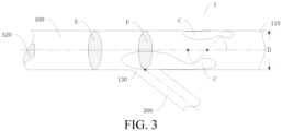
FIG. 3 is a schematic diagram of a high-temperature exhaust gas area in the air inlet pipe of the EGR system according to an embodiment of the present disclosure; -
FIG. 4 is a schematic diagram of arrangement of an engine assembly according to an embodiment of the present disclosure; -
FIG. 5 is a schematic structural diagram of the engine assembly according to an embodiment of the present disclosure; and -
FIG. 6 is a schematic diagram of a vehicle according to an embodiment of the present disclosure. - In the drawings:
-
EGR system 1,Engine assembly 2,Vehicle 3, -
Air inlet pipe 100,Air inlet 110,Air supply port 120,Air return port 130, - Air
inlet control valve 200,Air filter 210, - Exhaust
gas return pipe 300, -
Exhaust pipe 400, -
Pressurizer 500, First end 510,Second end 520, -
Catalyst 600, Air returncontrol valve 700,EGR cooler 800,Intercooler 810, -
Engine 900,Air inlet manifold 910,Exhaust manifold 920. - Embodiments of the present disclosure are described below in detail, and the embodiments described with reference to drawings are exemplary.
- In the description of the present disclosure, it should be understood that orientation or position relationships indicated by terms such as "center", "longitudinal", "transverse", "length", "width", "thickness", "upper", "lower", "front", "rear", "left", "right", "vertical", "horizontal", "top", "bottom", "inside", "outside", "clockwise", "anticlockwise", "axial direction", "radial direction", and "circumferential direction" are based on orientation or position relationships shown in the drawings, and are merely used for ease and brevity of description of the present disclosure, rather than indicating or implying that the mentioned device or element needs to have a particular orientation or be constructed and operated in a particular orientation. Therefore, the terms should not be construed as a limitation on the present disclosure.
- In the description of the present disclosure, a "first feature" and a "second feature" may explicitly or implicitly include one or more features.
- In the description of the present disclosure, "multiple" means two or more.
- An exhaust gas recirculation (EGR)
system 1 in the embodiments of the present disclosure is described below with reference to the drawings. - As shown in
FIG. 1 to FIG. 4 , theEGR system 1 in the embodiments of the present disclosure includes anair inlet pipe 100, an airinlet control valve 200, an exhaustgas return pipe 300, and anexhaust pipe 400. - The
air inlet pipe 100 has anair inlet 110, anair supply port 120, and anair return port 130. Theair inlet 110 is configured to be in communication with air. Theair supply port 120 is configured to be in communication with anair inlet manifold 910 of anengine 900. In a length direction of theair inlet pipe 100, theair return port 130 is located between theair inlet 110 and theair supply port 120. The airinlet control valve 200 is arranged on theair inlet pipe 100. The airinlet control valve 200 is located between theair inlet 110 and theair return port 130. The exhaustgas return pipe 300 is in communication with theair return port 130. Theexhaust pipe 400 is in communication with the exhaustgas return pipe 300. Theexhaust pipe 400 is configured to be in communication with anexhaust manifold 920 of theengine 900. In the length direction of theair inlet pipe 100, a distance S exists between theair return port 130 and the airinlet control valve 200. Theair inlet pipe 100 has an inner diameter D. S/D≤2. - For example, an
air filter 210 is arranged on theair inlet pipe 100. Theair filter 210 is located between theair inlet port 110 and the airinlet control valve 200. - It should be noted that, "S" may be a minimum distance between a center point of the
air return port 130 and the airinlet control valve 200 in the length direction of theair inlet pipe 100. - According to the
EGR system 1 in the embodiments of the present disclosure, theair inlet pipe 100 is provided with theair inlet 110, theair supply port 120, and theair return port 130, theair inlet 110 is configured to be in communication with the air, and theair supply port 120 is configured to be in communication theair inlet manifold 910 of theengine 900. In this way, fresh air can enter theair inlet pipe 100 through theair inlet 110 of theair inlet pipe 100, and be distributed to each cylinder of theengine 900 through theair supply port 120 and theair inlet manifold 910 of theengine 900, so that theengine 900 can operate normally. - In addition, in the length direction of the
air inlet pipe 100, theair return port 130 is located between theair inlet port 110 and theair supply port 120, theexhaust pipe 400 is configured to be in communication with theexhaust manifold 920 of theengine 900, and the exhaustgas return pipe 300 is in communication with theexhaust pipe 400 and theair return port 130. In this way, an exhaust gas generated by theengine 900 can enter the exhaustgas return pipe 300 through theexhaust pipe 400, and then enter theair inlet pipe 100 through theair return port 130, so that incompletely combusted air in the exhaust gas can re-enter theengine 900 through theair inlet pipe 100, thus achieving exhaust gas circulation and reuse. - Moreover, the air
inlet control valve 200 is arranged on theair inlet pipe 100, and the airinlet control valve 200 is located between theair inlet 110 and theair return port 130. In this way, after the exhaust gas enters theair inlet pipe 100 through theair return port 130, the exhaust gas can directly flow toward theengine 900, that is, the airinlet control valve 200 does not prevent the exhaust gas from cyclically entering theengine 900, so that the exhaust gas and the fresh air can enter theengine 900 in mixture in theair inlet pipe 100. Therefore, a more reasonable structural arrangement is achieved. - In addition, in the length direction of the
air inlet pipe 100, the distance S exists between theair return port 130 and the airinlet control valve 200. Theair inlet pipe 100 has the inner diameter D. S/D≤2. A theoretical flow area on a side of the airinlet control valve 200 facing theair supply port 120 is defined as an area C below. As shown inFIG. 3 , due to a throttling effect of the airinlet control valve 200, a flow section of a theoretical area of a pipeline on the side of the airinlet control valve 200 facing theair supply port 120 is reduced. The decrease in the flow section of the theoretical area results in an increase in an airflow velocity in the theoretical flow area. Since the airflow velocity in the above area C is greater than an airflow velocity in an area of theair inlet pipe 100 between theair supply port 120 and the airinlet control valve 200, a dynamic pressure in the area C is larger, and a static pressure in the area C is less than that in the area of theair inlet pipe 100 between theair supply port 120 and the airinlet control valve 200. Setting the distance between theair return port 130 and the airinlet control valve 200 to be relatively small helps increase a pressure difference between theair return port 130 and the exhaustgas return pipe 300, thereby increasing an EGR rate, and reducing a pumping loss. - A pressure difference in the area C and a pressure difference in the area of the
air inlet pipe 100 between theair supply port 120 and the airinlet control valve 200 are described with reference toFIG. 3 by using examples. - First, it is assumed that an area E and an area F exist in the
air inlet pipe 100. The area F corresponds to a position of theair return port 130. The area E is located on a side of theair return port 130 away from the airinlet control valve 200. - A theoretical flow section of the area E is E1. A theoretical flow section of the area F is F1. In addition, a total pressure of the area F is P1, and an airflow velocity is v1. A dynamic pressure of the area F is Pdynamic 1, and a static pressure is Pstatic 1. P1=Pdynamic 1+Pstatic 1. A total pressure of the area E is P2, and an airflow velocity is v2. A dynamic pressure of the area E is Pdynamic 2, and a static pressure is Pstatic 2. P2=Pdynamic 2+Pstatic 2.
- Since no throttling feature exists between the area E and the area F, no significant pressure loss or throttling effect is generated between the area E and the area F, and the total pressure of the area E is approximately equal to the total pressure of the area F, that is, P1=P2.
- Due to the throttling effect of the air
inlet control valve 200, an airflow can merely move toward theair supply port 120 through the area C. Therefore, a theoretical flow section of an airflow on a side close to a mixing valve and facing theair supply port 120 is significantly reduced. The reduced section F1 is significantly less than the section E1. Since the reduction in the section results in an increase in an airflow velocity, a gas flow velocity at the section F1 is relatively large. The airflow velocity at the section F1 is greater than an airflow velocity at the section E1. - According to a dynamic pressure calculation equation Pdynamic=ρv 2/2, a dynamic pressure at the section F1 is increased, and Pdynamic 2<Pdynamic 1.
- In summary, Pstatic 1<Pstatic 2.
- Therefore, the static pressure in the area C is relatively low, and a static pressure outside the area C is relatively high. Setting S/D≤2 helps increase the pressure difference between the
air inlet port 110 and the exhaustgas return pipe 300, increase an exhaust gas circulation amount, and reduce the pumping loss, to achieve a maximum EGR rate with a minimum pumping loss, thereby reducing a fuel consumption rate. - In this way, the
EGR system 1 in the embodiments of the present disclosure has advantages such as a high EGR rate, a low pumping loss, and low oil consumption for theengine 900. - In some specific embodiments of the present disclosure, as shown in
FIG. 2 andFIG. 4 , theEGR system 1 further includes apressurizer 500. - The
pressurizer 500 has afirst end 510 and asecond end 520. Thefirst end 510 is arranged on theexhaust pipe 400. Thefirst end 510 is located between theengine 900 and the exhaustgas return pipe 300. Thesecond end 520 is arranged on theair inlet pipe 100. Thesecond end 520 is located between theair return port 130 and theair supply port 120. Specifically, when theengine 900 operates, theexhaust pipe 400 discharges an exhaust gas. The exhaust gas can drive thefirst end 510 of thepressurizer 500 to operate. Thefirst end 510 transmits power to thesecond end 520. A rotation direction of thesecond end 520 of thepressurizer 500 is the same as a flowing direction of a gas in theair inlet pipe 100, to pressurize the gas in theair inlet pipe 100. In this way, the circulating exhaust gas and the fresh air can enter theengine 900 more quickly. - In the length direction of the
air inlet pipe 100, a distance L exists between theair return port 130 and thesecond end air return port 130 and thesecond end 520 in the length direction of theair inlet pipe 100. For example, "L" is a minimum distance between the center point of theair return port 130 and thesecond end 520 in the length direction of theair inlet pipe 100. - It should be noted that, during the operation of the
engine 900, a high-temperature recirculation exhaust gas enters theair inlet pipe 100 through theair return port 130. In theair inlet pipe 100, the high-temperature exhaust gas gets mixed with fresh air entering the air inlet pipe through the airinlet control valve 200. In an area (for example, an area G) near theair return port 130, the high-temperature exhaust gas has a relatively high temperature (which usually ranges from 120°C to 150°C), while the fresh air has a relatively low temperature. - Through setting of 2≤L/D, in the length direction of the
air inlet pipe 100, the distance L between theair return port 130 and thesecond end 520 is relatively large, so that the high-temperature exhaust gas and the fresh air fully mix and then enter thesecond end 520 of thepressurizer 500. In this way, a risk of surge of thepressurizer 500 is reduced, pressurization efficiency of thepressurizer 500 is improved, and reliable operation of thepressurizer 500 is ensured. Moreover, through setting of L/D≤20, a throttling loss as a result of an excessively long airflow channel can be avoided, which further reduces the pumping loss of theengine 900. In this way, a relatively large EGR rate can be achieved with a relatively low pumping loss, thereby achieving low oil consumption in a full load mode. - In some specific embodiments of the present disclosure, as shown in
FIG. 1 andFIG. 2 , theEGR system 1 further includes apressurizer 500. Thepressurizer 500 has afirst end 510 and asecond end 520. Thefirst end 510 is arranged on theexhaust pipe 400, and is located between theengine 900 and the exhaustgas return pipe 300. Thesecond end 520 is arranged on theair inlet pipe 100, and is located between theair return port 130 and theair supply port 120. In the length direction of theair inlet pipe 100, a distance L exists between theair return port 130 and thesecond end 520, and S<L. Therefore, the distance S between theair return port 130 and the airinlet control valve 200 is smaller, and the distance L between theair return port 130 and thesecond end 520 is larger, which helps increase the pressure difference between theair inlet port 110 and the exhaustgas return pipe 300, increase the exhaust gas circulation amount, and reduce the pumping loss, to achieve a maximum EGR rate with a minimum pumping loss, thereby reducing the fuel consumption rate. In addition, the high-temperature exhaust gas and the fresh air can fully mix and then enter thesecond end 520 of thepressurizer 500. In this way, the risk of surge of thepressurizer 500 is reduced, the pressurization efficiency of thepressurizer 500 is improved, and the reliable operation of thepressurizer 500 is ensured. - In some specific embodiments of the present disclosure, as shown in
FIG. 1 andFIG. 2 , theEGR system 1 further includes acatalyst 600. Thecatalyst 600 is arranged on theexhaust pipe 400. Thecatalyst 600 is located between the exhaustgas return pipe 300 and thefirst end 510. - For example, the
catalyst 600 may be a three-way catalyst. Through the arrangement of thecatalyst 600, an exhaust gas emitted by theengine 900 can be purified. For example, thecatalyst 600 can convert CO, HC, or NOx in the exhaust gas into harmless carbon dioxide, water, and nitrogen, to reduce an amount of harmful gases discharged into the air, and can further purify the exhaust gas into a cleaner gas before the exhaust gas enters theair inlet pipe 100, which facilitates reuse by theengine 900, and reduces problems such as carbon deposition, coking, and gas path blockage in theengine 900. - In some specific embodiments of the present disclosure, as shown in
FIG. 2 to FIG. 4 , in a direction from theair return port 130 toward theexhaust pipe 400, that is, in a direction from an end of the exhaustgas return pipe 300 connected with theair return port 130 to an end of the exhaustgas return pipe 300 away from theair return port 130, the exhaustgas return pipe 300 is gradually inclined toward the airinlet control valve 200. - Therefore, an included angle between a flowing direction of a circulating exhaust gas in the exhaust
gas return pipe 300 and a flowing direction of fresh air in theair inlet pipe 100 is relatively small, so that the exhaust gas can quickly enter theair inlet pipe 100, which ensures that the exhaust gas can enter theair inlet pipe 100 more smoothly, thereby further improving the EGR rate. Moreover, a flowing collision between the exhaust gas and the fresh air can be mitigated, and the exhaust gas can quickly get mixed with the fresh air after entering theair inlet pipe 100, and flow more smoothly, which further increases a flow rate of the mixed air, helps the mixed air enter theengine 900, improves the EGR rate, and reduces the pumping loss, thereby achieving low oil consumption in the full load mode. - Further, as shown in
FIG. 2 to FIG. 4 , an included angle W between theair inlet pipe 100 and the exhaustgas return pipe 300 ranges from 10° to 90°. For example, the included angle between theair inlet pipe 100 and the exhaustgas return pipe 300 may be 10°, 15°, 20°, 25°, 30°, 35°, 40°, 45°, 50°, 55°, 60°, 65°, 70°, 75°, 80°, 85°, or 90°. However, the included angle is not limited thereto. - It should be noted that, an included angle between a part of the
air inlet pipe 100 connected with the exhaustgas return pipe 300 and the exhaustgas return pipe 300 ranges from 10° to 90°(including endpoint values). - In this way, an excessively low flow rate of the exhaust gas in the exhaust
gas return pipe 300 in theair inlet pipe 100 as a result of an excessively small included angle between theair inlet pipe 100 and the exhaustgas return pipe 300 can be avoided, which enables the exhaust gas to quickly enter theair inlet pipe 100, and ensures smooth flowing of the exhaust gas. In addition, the flowing direction of the exhaust gas in the exhaustgas return pipe 300 can be prevented from being opposite to the flowing direction of the fresh air in theair inlet pipe 100 as a result of an excessively large included angle between theair inlet pipe 100 and the exhaustgas return pipe 300, which prevents the fresh air in theair inlet pipe 100 from colliding with the exhaust gas, and ensures an overall flow rate of the exhaust gas and the fresh air in theair inlet pipe 100. In this way, the pumping loss can be reduced, and a relatively high EGR rate can be ensured, thereby achieving low oil consumption in the full load mode. - In some specific embodiments of the present disclosure, as shown in
FIG. 1 andFIG. 5 , theEGR system 1 further includes an airreturn control valve 700 and anEGR cooler 800. - The air
return control valve 700 is arranged on the exhaustgas return pipe 300. The airreturn control valve 700 is configured to control a gas flow rate in the exhaustgas return pipe 300. Specifically, the airreturn control valve 700 can regulate a flow rate of the exhaust gas in the exhaustgas return pipe 300. TheEGR cooler 800 is arranged on the exhaustgas return pipe 300. TheEGR cooler 800 is located between the airreturn control valve 700 and theexhaust pipe 400. TheEGR cooler 800 is configured to cool the gas in the exhaustgas return pipe 300. - For example, when the
engine 900 does not operate, an initial state of the airreturn control valve 700 is closed, and an initial state of the airinlet control valve 200 is open. During operation of theengine 900, theengine 900 discharges an exhaust gas. In this case, the airreturn control valve 700 may be gradually opened, so that the exhaust gas returns to theengine 900 through the exhaustgas return pipe 300. When theengine 900 requires a high EGR rate, an opening degree of the airreturn control valve 700 may be increased, and the airinlet control valve 200 may be properly closed, to increase a rate of exhaust gases entering theair inlet pipe 100, thereby improving the EGR rate. - In addition, through the arrangement of the
EGR cooler 800, the high-temperature exhaust gas can be cooled in the exhaustgas return pipe 300, so that the exhaust gas has a relatively low temperature when entering theair inlet pipe 100. In this way, the mixed gas of the exhaust gas and the fresh air is prevented from an excessively high temperature, which further reduces the risk of surge of thepressurizer 500, increases the pressurization efficiency of thepressurizer 500, and ensures the reliable operation of thepressurizer 500. Moreover, the exhaust gas in the exhaustgas return pipe 300 needs to be cooled through theEGR cooler 800 before passing through the airreturn control valve 700, so that damage to the airreturn control valve 700 caused by the high-temperature gas can be avoided, thereby prolonging a service life of the airreturn control valve 700. - An
engine assembly 2 in the embodiments of the present disclosure is described below with reference toFIG. 1 to FIG. 5 . - As shown in
FIG. 1 andFIG. 5 , theengine assembly 2 includes theEGR system 1 in the above embodiments of the present disclosure and anengine 900. Theengine 900 has anair inlet manifold 910 and anexhaust manifold 920. Theair inlet manifold 910 is in communication with theair inlet pipe 100 of theEGR system 1. Theexhaust manifold 920 is in communication with theexhaust pipe 400 of theEGR system 1. - A quantity of air inlet manifolds 910 may be in one-to-one correspondence with a quantity of cylinders of the
engine 900. A quantity ofexhaust manifolds 920 may be in one-to-one correspondence with the quantity of cylinders of theengine 900. A gas in theair inlet pipe 100 may enter the cylinders of theengine 900 through the multiple air inlet manifolds 910 respectively, and exhaust gases generated after combustion in the cylinders may be discharged to theexhaust pipe 400 through the multiple air inlet manifolds 910 respectively. - The
engine assembly 2 in the embodiments of the present disclosure adopts theEGR system 1 in the above embodiments of the present disclosure, which has advantages such as a high EGR rate, a low pumping loss, and low oil consumption for theengine 900. - In some specific embodiments of the present disclosure, as shown in
FIG. 1 andFIG. 5 , theengine assembly 2 further includes anintercooler 810. Theintercooler 810 is arranged on theair inlet pipe 100. Theintercooler 810 is adjacent to theair inlet manifold 910 of theengine 900. In this way, theintercooler 810 can further reduce a temperature of a mixed gas of air and an exhaust gas entering theengine 900, to avoid an excessive high combustion temperature of theengine 900, thereby further reducing fuel consumption for theengine 900, reducing oil consumption, and improving an endurance. - A
vehicle 3 in the embodiments of the present disclosure is described below with reference toFIG. 6 . Thevehicle 3 includes theengine assembly 2 in the above embodiments of the present disclosure. - The
vehicle 3 in the embodiments of the present disclosure adopts theengine assembly 2 in the above embodiments of the present disclosure, which has advantages such as a high EGR rate, a low pumping loss, and low fuel consumption for theengine 900. - Other compositions and operations of the
EGR system 1, theengine assembly 2, and thevehicle 3 in the embodiments of the present disclosure are known to a person of ordinary skill in the art, and therefore are not described in detail herein. - In the description of this specification, descriptions provided with reference to the terms such as "an embodiment", "some embodiments", "an exemplary embodiment", "an example", "a specific example", and "some examples" mean that specific features, structures, materials, or characteristics described with reference to the embodiment or example are included in at least one embodiment or example of the present disclosure. In this specification, exemplary descriptions of the above terms do not necessarily refer to the same embodiment or example.
- Although the embodiments of the present disclosure have been shown and described, a person of ordinary skill in the art should understand that various changes, modifications, replacements, and variations may be made to the embodiments without departing from the principle and spirit of the present disclosure. The scope of the present disclosure is defined by the appended claims and their equivalents.
Claims (14)
- An exhaust gas recirculation system (1), comprising:an air inlet pipe (100), the air inlet pipe (100) having an air inlet (110), an air supply port (120), and an air return port (130), the air inlet (110) being configured to be in communication with air; the air supply port (120) being configured to be in communication with an air inlet manifold (910) of an engine (900); and in a length direction of the air inlet pipe (100), the air return port (130) being located between the air inlet (110) and the air supply port (120);an air inlet control valve (200), the air inlet control valve (200) being arranged on the air inlet pipe (100); and the air inlet control valve (200) being located between the air inlet (110) and the air return port (130);an exhaust gas return pipe (300), the exhaust gas return pipe (300) being in communication with the air return port (130); andan exhaust pipe (400), the exhaust pipe (400) being in communication with the exhaust gas return pipe (300); and the exhaust pipe (400) being configured to be in communication with an exhaust manifold (920) of the engine (900),wherein in the length direction of the air inlet pipe (100), a distance S exists between the air return port (130) and the air inlet control valve (200); and the air inlet pipe (100) has an inner diameter D, wherein S and D meet S/D≤2.
- The exhaust gas recirculation system (1) according to claim 1, further comprising:a pressurizer (500), the pressurizer (500) having a first end (510) and a second end (520); the first end (510) being arranged on the exhaust pipe (400); the first end (510) being located between the engine and the exhaust gas return pipe (300); the second end (520) being arranged on the air inlet pipe (100); and the second end (520) being located between the air return port (130) and the air supply port (120),wherein in the length direction of the air inlet pipe (100), a distance L exists between the air return port (130) and the second end (520), wherein L and D meet 2≤L/D≤20.
- The exhaust gas recirculation system (1) according to claim 1, further comprising:a pressurizer (500), the pressurizer (500) having a first end (510) and a second end (520); the first end (510) being arranged on the exhaust pipe (400); the first end (510) being located between the engine and the exhaust gas return pipe (300); the second end (520) being arranged on the air inlet pipe (100); and the second end (520) being located between the air return port (130) and the air supply port (120),wherein in the length direction of the air inlet pipe (100), a distance L exists between the air return port (130) and the second end (520), wherein L and S meet S<L.
- The exhaust gas recirculation system (1) according to claim 3, further comprising:
a catalyst (600), the catalyst (600) being arranged on the exhaust pipe (400); and the catalyst (600) being located between the exhaust gas return pipe (300) and the first end (510). - The exhaust gas recirculation system (1) according to claim 4, wherein the catalyst (600) is a three-way catalyst.
- The exhaust gas recirculation system (1) according to any of claims 1 to 5, wherein in a direction from the air return port (130) toward the exhaust pipe (400), the exhaust gas return pipe (300) is gradually inclined toward the air inlet control valve (200).
- The exhaust gas recirculation system (1) according to claim 6, wherein an included angle between the air inlet pipe (100) and the exhaust gas return pipe (300) ranges from 10° to 90°.
- The exhaust gas recirculation system (1) according to any of claims 1 to 7, further comprising:an air return control valve (700), the air return control valve (700) being arranged on the exhaust gas return pipe (300); and the air return control valve (700) being configured to control a gas flow rate in the exhaust gas return pipe (300); andan exhaust gas recirculation cooler (800), the exhaust gas recirculation cooler (800) being arranged on the exhaust gas return pipe (300); the exhaust gas recirculation cooler (800) being located between the air return control valve (700) and the exhaust pipe (300); and the exhaust gas recirculation cooler (800) being configured to cool a gas in the exhaust gas return pipe (300).
- The exhaust gas recirculation system (1) according to any of claims 1 to 8, wherein an air filter (210) is arranged on the air inlet pipe (100); and the air filter (210) is located between the air inlet port (110) and the air inlet control valve (200).
- An engine assembly (2), comprising:the exhaust gas recirculation system (1) according to any of claims 1 to 9; andan engine (900), the engine (900) having an air inlet manifold (910) and an exhaust manifold (920); the air inlet manifold (910) being in communication with the air inlet pipe (100) of the exhaust gas recirculation system (1); and the exhaust manifold (920) being in communication with the exhaust pipe (400) of the exhaust gas recirculation system (1).
- The engine assembly (2) according to claim 10, further comprising:
an intercooler (810), the intercooler (810) being arranged on the air inlet pipe (100); and the intercooler (810) being adjacent to the air inlet manifold (910) of the engine. - The engine assembly (2) according to claim 10, wherein a quantity of air inlet manifolds (910) is the same as a quantity of cylinders of the engine (900).
- The engine assembly (2) according to claim 10, wherein a quantity of exhaust manifolds (920) is the same as a quantity of cylinders of the engine (900).
- A vehicle (3), comprising the engine assembly (2) according to any of claims 10 to 13.
Applications Claiming Priority (2)
| Application Number | Priority Date | Filing Date | Title |
|---|---|---|---|
| CN202210445423.9A CN116988897A (en) | 2022-04-26 | 2022-04-26 | Exhaust gas recirculation systems, engine assemblies and vehicles |
| PCT/CN2023/078769 WO2023207309A1 (en) | 2022-04-26 | 2023-02-28 | Exhaust gas recirculation system, engine assembly, and vehicle |
Publications (2)
| Publication Number | Publication Date |
|---|---|
| EP4517079A1 true EP4517079A1 (en) | 2025-03-05 |
| EP4517079A4 EP4517079A4 (en) | 2026-04-15 |
Family
ID=88517257
Family Applications (1)
| Application Number | Title | Priority Date | Filing Date |
|---|---|---|---|
| EP23794745.2A Pending EP4517079A4 (en) | 2022-04-26 | 2023-02-28 | EXHAUST ENGINE RECIRCULATION SYSTEM, ENGINE LAYOUT AND VEHICLE |
Country Status (6)
| Country | Link |
|---|---|
| US (1) | US12503990B2 (en) |
| EP (1) | EP4517079A4 (en) |
| JP (1) | JP7819356B2 (en) |
| CN (1) | CN116988897A (en) |
| CA (1) | CA3255118A1 (en) |
| WO (1) | WO2023207309A1 (en) |
Family Cites Families (25)
| Publication number | Priority date | Publication date | Assignee | Title |
|---|---|---|---|---|
| CA2003218A1 (en) * | 1988-11-18 | 1990-05-18 | Minobu Sukimoto | Adapter for intake manifold |
| JPH09151809A (en) * | 1995-12-04 | 1997-06-10 | Hitachi Ltd | Exhaust gas recirculation device for engine and exhaust gas recirculation method |
| JPH10213019A (en) * | 1996-05-14 | 1998-08-11 | Nippon Soken Inc | Exhaust gas recirculation device |
| JPH10325367A (en) * | 1997-05-27 | 1998-12-08 | Nissan Motor Co Ltd | Engine exhaust gas recirculation system |
| JP3992784B2 (en) * | 1997-05-30 | 2007-10-17 | 日産自動車株式会社 | Engine intake system |
| US6988365B2 (en) * | 2003-11-19 | 2006-01-24 | Southwest Research Institute | Dual loop exhaust gas recirculation system for diesel engines and method of operation |
| JP4380545B2 (en) * | 2004-02-20 | 2009-12-09 | トヨタ自動車株式会社 | Internal combustion engine and operation control device for internal combustion engine |
| DE102004044893A1 (en) * | 2004-09-14 | 2006-03-30 | Volkswagen Ag | Exhaust gas recirculation device and method for operating an exhaust gas recirculation device |
| WO2010071013A1 (en) * | 2008-12-17 | 2010-06-24 | アイシン精機株式会社 | Air intake manifold |
| US20120266594A1 (en) * | 2009-12-22 | 2012-10-25 | Borgwarner Inc. | Internal combustion engine |
| JP5561554B2 (en) * | 2011-01-27 | 2014-07-30 | アイシン精機株式会社 | Intake device for internal combustion engine |
| DE112012005656B4 (en) * | 2012-01-12 | 2019-10-02 | Mitsubishi Electric Corporation | Exhaust gas recirculation valve |
| US20140150759A1 (en) * | 2012-12-04 | 2014-06-05 | GM Global Technology Operations LLC | Engine Including External EGR System |
| JP6434749B2 (en) * | 2013-12-27 | 2018-12-05 | 三菱重工業株式会社 | Exhaust gas recirculation device and engine system including the exhaust gas recirculation device |
| CN106150770A (en) * | 2015-03-27 | 2016-11-23 | 北京汽车动力总成有限公司 | A kind of gas recirculation system and automobile |
| US9617933B2 (en) * | 2015-08-03 | 2017-04-11 | Borgwarner Inc. | Low pressure EGR control using throttling |
| JP6551046B2 (en) * | 2015-08-20 | 2019-07-31 | 日産自動車株式会社 | engine |
| GB2544731B (en) * | 2015-11-19 | 2019-02-20 | Ford Global Tech Llc | An exhaust gas recirculation apparatus |
| CN110168209B (en) * | 2017-01-16 | 2022-03-04 | 日产自动车株式会社 | Method for controlling internal combustion engine and control device for internal combustion engine |
| JP6477764B2 (en) * | 2017-03-30 | 2019-03-06 | マツダ株式会社 | Intake passage structure of multi-cylinder engine |
| CN108730014B (en) * | 2017-04-21 | 2020-03-06 | 北京汽车动力总成有限公司 | Engine and automobile |
| DE102017209789B3 (en) * | 2017-06-09 | 2018-05-03 | Ford Global Technologies, Llc | Supercharged internal combustion engine with intake-side bypass line and method for operating such an internal combustion engine |
| CN208010484U (en) | 2018-02-09 | 2018-10-26 | 郑州日产汽车有限公司 | Automobile low pressure egr system |
| US20210340935A1 (en) * | 2018-07-20 | 2021-11-04 | Eaton Intelligent Power Limited | Egr ejector system |
| CN109798205B (en) | 2019-04-11 | 2024-01-12 | 潍柴动力股份有限公司 | EGR mixer and engine with same |
-
2022
- 2022-04-26 CN CN202210445423.9A patent/CN116988897A/en active Pending
-
2023
- 2023-02-28 EP EP23794745.2A patent/EP4517079A4/en active Pending
- 2023-02-28 CA CA3255118A patent/CA3255118A1/en active Pending
- 2023-02-28 WO PCT/CN2023/078769 patent/WO2023207309A1/en not_active Ceased
- 2023-02-28 JP JP2024559729A patent/JP7819356B2/en active Active
-
2024
- 2024-09-24 US US18/895,344 patent/US12503990B2/en active Active
Also Published As
| Publication number | Publication date |
|---|---|
| JP2025511984A (en) | 2025-04-16 |
| US12503990B2 (en) | 2025-12-23 |
| JP7819356B2 (en) | 2026-02-24 |
| CA3255118A1 (en) | 2025-03-31 |
| US20250012242A1 (en) | 2025-01-09 |
| WO2023207309A1 (en) | 2023-11-02 |
| CN116988897A (en) | 2023-11-03 |
| EP4517079A4 (en) | 2026-04-15 |
Similar Documents
| Publication | Publication Date | Title |
|---|---|---|
| US7451749B2 (en) | Cooler device in a vehicle | |
| CN105508088B (en) | The engine with supercharger gas recirculation system and its application method of spark ignition type | |
| CN103470408A (en) | EGR (Exhaust Gas Recirculation) system used for marine medium-speed diesel engine | |
| CN110469434A (en) | A kind of exhaust gas recooling system | |
| US12503990B2 (en) | Exhaust gas recirculation system, engine assembly, and vehicle | |
| KR101683495B1 (en) | Engine system having turbo charger | |
| SE521515C2 (en) | Exhaust fume recirculation arrangement for vehicle engine, has gas cooler cleaned using backflow of air through return pipe | |
| CN210106029U (en) | Engine and vehicle | |
| KR20120067020A (en) | Vehicle engine cooling system | |
| CN118653923A (en) | Engine system and control method | |
| CN212479377U (en) | Secondary air supplementing device and engine | |
| JP2000161146A (en) | EGR device for multi-cylinder engine | |
| JP5310437B2 (en) | EGR diffusion unit | |
| CN208793122U (en) | Gas recirculation system and engine | |
| CN223089404U (en) | Engine cylinder cover assembly, engine, power assembly and vehicle | |
| CN218347474U (en) | Pulse converter | |
| JP5477484B2 (en) | EGR diffusion unit | |
| CN215860544U (en) | Engine exhaust gas recirculation system | |
| CN217682021U (en) | EGR engine and vehicle | |
| CN118640118B (en) | Venturi mixer and natural gas engine | |
| CN223120005U (en) | Exhaust manifold, engine and vehicle | |
| CN218151195U (en) | Engine air intake system, engine and vehicle | |
| JP4237107B2 (en) | EGR device | |
| KR102764111B1 (en) | Protection Structure for EGR | |
| JP2008190409A (en) | Multiple cylinder engine |
Legal Events
| Date | Code | Title | Description |
|---|---|---|---|
| STAA | Information on the status of an ep patent application or granted ep patent |
Free format text: STATUS: THE INTERNATIONAL PUBLICATION HAS BEEN MADE |
|
| PUAI | Public reference made under article 153(3) epc to a published international application that has entered the european phase |
Free format text: ORIGINAL CODE: 0009012 |
|
| STAA | Information on the status of an ep patent application or granted ep patent |
Free format text: STATUS: REQUEST FOR EXAMINATION WAS MADE |
|
| 17P | Request for examination filed |
Effective date: 20241031 |
|
| AK | Designated contracting states |
Kind code of ref document: A1 Designated state(s): AL AT BE BG CH CY CZ DE DK EE ES FI FR GB GR HR HU IE IS IT LI LT LU LV MC ME MK MT NL NO PL PT RO RS SE SI SK SM TR |
|
| DAV | Request for validation of the european patent (deleted) | ||
| DAX | Request for extension of the european patent (deleted) | ||
| A4 | Supplementary search report drawn up and despatched |
Effective date: 20260312 |
|
| RIC1 | Information provided on ipc code assigned before grant |
Ipc: F02M 26/17 20160101AFI20260306BHEP Ipc: F02M 26/06 20160101ALI20260306BHEP |