EP4517078A1 - Fuel shortage detection device for internal combustion engine, straddled vehicle, and fuel shortage detection method for internal combustion engine - Google Patents
Fuel shortage detection device for internal combustion engine, straddled vehicle, and fuel shortage detection method for internal combustion engine Download PDFInfo
- Publication number
- EP4517078A1 EP4517078A1 EP24192092.5A EP24192092A EP4517078A1 EP 4517078 A1 EP4517078 A1 EP 4517078A1 EP 24192092 A EP24192092 A EP 24192092A EP 4517078 A1 EP4517078 A1 EP 4517078A1
- Authority
- EP
- European Patent Office
- Prior art keywords
- fuel
- threshold value
- equal
- internal combustion
- combustion engine
- Prior art date
- Legal status (The legal status is an assumption and is not a legal conclusion. Google has not performed a legal analysis and makes no representation as to the accuracy of the status listed.)
- Granted
Links
Images






Classifications
-
- F—MECHANICAL ENGINEERING; LIGHTING; HEATING; WEAPONS; BLASTING
- F02—COMBUSTION ENGINES; HOT-GAS OR COMBUSTION-PRODUCT ENGINE PLANTS
- F02D—CONTROLLING COMBUSTION ENGINES
- F02D41/00—Electrical control of supply of combustible mixture or its constituents
- F02D41/02—Circuit arrangements for generating control signals
- F02D41/14—Introducing closed-loop corrections
- F02D41/1438—Introducing closed-loop corrections using means for determining characteristics of the combustion gases; Sensors therefor
- F02D41/1444—Introducing closed-loop corrections using means for determining characteristics of the combustion gases; Sensors therefor characterised by the characteristics of the combustion gases
- F02D41/1454—Introducing closed-loop corrections using means for determining characteristics of the combustion gases; Sensors therefor characterised by the characteristics of the combustion gases the characteristics being an oxygen content or concentration or the air-fuel ratio
-
- F—MECHANICAL ENGINEERING; LIGHTING; HEATING; WEAPONS; BLASTING
- F02—COMBUSTION ENGINES; HOT-GAS OR COMBUSTION-PRODUCT ENGINE PLANTS
- F02D—CONTROLLING COMBUSTION ENGINES
- F02D41/00—Electrical control of supply of combustible mixture or its constituents
- F02D41/02—Circuit arrangements for generating control signals
- F02D41/14—Introducing closed-loop corrections
- F02D41/1438—Introducing closed-loop corrections using means for determining characteristics of the combustion gases; Sensors therefor
- F02D41/1493—Details
- F02D41/1495—Detection of abnormalities in the air/fuel ratio feedback system
-
- F—MECHANICAL ENGINEERING; LIGHTING; HEATING; WEAPONS; BLASTING
- F02—COMBUSTION ENGINES; HOT-GAS OR COMBUSTION-PRODUCT ENGINE PLANTS
- F02D—CONTROLLING COMBUSTION ENGINES
- F02D41/00—Electrical control of supply of combustible mixture or its constituents
- F02D41/24—Electrical control of supply of combustible mixture or its constituents characterised by the use of digital means
- F02D41/2406—Electrical control of supply of combustible mixture or its constituents characterised by the use of digital means using essentially read only memories
- F02D41/2425—Particular ways of programming the data
- F02D41/2429—Methods of calibrating or learning
- F02D41/2432—Methods of calibration
-
- F—MECHANICAL ENGINEERING; LIGHTING; HEATING; WEAPONS; BLASTING
- F02—COMBUSTION ENGINES; HOT-GAS OR COMBUSTION-PRODUCT ENGINE PLANTS
- F02D—CONTROLLING COMBUSTION ENGINES
- F02D41/00—Electrical control of supply of combustible mixture or its constituents
- F02D41/24—Electrical control of supply of combustible mixture or its constituents characterised by the use of digital means
- F02D41/2406—Electrical control of supply of combustible mixture or its constituents characterised by the use of digital means using essentially read only memories
- F02D41/2425—Particular ways of programming the data
- F02D41/2429—Methods of calibrating or learning
- F02D41/2451—Methods of calibrating or learning characterised by what is learned or calibrated
- F02D41/2454—Learning of the air-fuel ratio control
-
- F—MECHANICAL ENGINEERING; LIGHTING; HEATING; WEAPONS; BLASTING
- F02—COMBUSTION ENGINES; HOT-GAS OR COMBUSTION-PRODUCT ENGINE PLANTS
- F02D—CONTROLLING COMBUSTION ENGINES
- F02D2200/00—Input parameters for engine control
- F02D2200/02—Input parameters for engine control the parameters being related to the engine
- F02D2200/10—Parameters related to the engine output, e.g. engine torque or engine speed
- F02D2200/101—Engine speed
-
- F—MECHANICAL ENGINEERING; LIGHTING; HEATING; WEAPONS; BLASTING
- F02—COMBUSTION ENGINES; HOT-GAS OR COMBUSTION-PRODUCT ENGINE PLANTS
- F02D—CONTROLLING COMBUSTION ENGINES
- F02D2200/00—Input parameters for engine control
- F02D2200/02—Input parameters for engine control the parameters being related to the engine
- F02D2200/10—Parameters related to the engine output, e.g. engine torque or engine speed
- F02D2200/1015—Engines misfires
Definitions
- the present invention relates to a fuel shortage detection device for an internal combustion engine, a straddled vehicle, and a method for detecting fuel shortage of an internal combustion engine.
- JP 2018-25158 A discloses an engine controller having an air-fuel ratio detection section that detects the air-fuel ratio of the engine, a rotation fluctuation deriving section that derives a rotation fluctuation value of the engine, and a fuel shortage misfire determination section that determines that the engine is misfiring due to shortage of fuel (hereinafter referred to as fuel shortage).
- the fuel shortage misfire determination section counts the number of times that the engine rotation fluctuation value is equal to or greater than a predetermined rotation fluctuation threshold value, and determines that the engine is misfiring due to fuel shortage when the count is equal to or greater than a predetermined count threshold value.
- the engine controller disclosed in JP 2018-25158 A determines engine fuel shortage based on the engine rotation fluctuation value when a precondition is met, where the precondition is that the air-fuel ratio of the exhaust gas is equal to or greater than an air-fuel ratio threshold value.
- said object is solved by a fuel shortage detection device for an internal combustion engine having the features of independent claim 1. Moreover, according to the present invention said object is solved by a fuel shortage detection method for an internal combustion engine having the features of independent claim 7. Preferred embodiments are laid down in the dependent claims.
- a fuel shortage detection device for an internal combustion engine disclosed herein includes: an O2 sensor arranged in an exhaust passage of the internal combustion engine that detects an oxygen concentration of a gas flowing in the exhaust passage; and a determination device, which is a computer connected to the O2 sensor.
- the determination device includes: an air-fuel ratio determination section that determines whether an air-fuel ratio of the gas is equal to or greater than a first threshold value based on the detection result of the O2 sensor; an accumulated time calculation section that calculates an accumulated time, which is an amount of time over which the air-fuel ratio of the gas is determined to be equal to or greater than the first threshold value by the air-fuel ratio determination section; an accumulated time reset section that resets the accumulated time accumulated by the accumulated time calculation section at every predetermined time interval; an accumulated time determination section that determines whether the accumulated time is equal to or greater than a predetermined second threshold value; and a fuel shortage determination section that determines that there is fuel shortage when the accumulated time becomes equal to or greater than the second threshold value.
- the lean state may not necessarily continue, and the lean state and the non-lean state may be repeated. However, even in this case, the lean state is repeated and the accumulated time of the lean state increases.
- the fuel shortage detection device described above it is possible to detect fuel shortage based on the accumulated time of the lean state over which the air-fuel ratio is equal to or greater than the first threshold value. Now, where the fuel supply is unstable or the detection accuracy of the O2 sensor is relatively low, the lean state may be determined temporarily from the detection result of the O2 sensor even when there is no actual fuel shortage.
- the lean state in such cases does not last long, but as the time of the lean state is accumulated, the accumulated time will eventually become equal to or greater than the second threshold value, leading to false determination of fuel shortage.
- the accumulated time is reset at every predetermined time interval. Therefore, it is possible to suppress the influence of the lean state occurring due to causes other than fuel shortage, thus improving the fuel shortage detection accuracy.
- the fuel shortage detection device may include a rotation speed sensor connected to the determination device that detects a rotation speed of the internal combustion engine.
- the determination device may include: a fluctuation value calculation section that calculates a fluctuation value of the rotation speed of the internal combustion engine; and a fluctuation value determination section that determines whether the fluctuation value of the rotation speed of the internal combustion engine is equal to or greater than a predetermined third threshold value.
- the fuel shortage determination section may be configured to determine that there is fuel shortage when the accumulated time is equal to or greater than the second threshold value and the fluctuation value of the rotation speed of the internal combustion engine is equal to or greater than the third threshold value.
- the fuel shortage detection device may include a fuel sensor connected to the determination device that detects whether an amount of fuel stored in a fuel tank is less than or equal to a predetermined fourth threshold value.
- the fuel shortage determination section may be configured to determine that there is fuel shortage when the accumulated time is equal to or greater than the second threshold value and the amount of fuel stored in the fuel tank is less than or equal to the fourth threshold value.
- the fuel shortage detection device may include: a rotation speed sensor connected to the determination device that detects a rotation speed of the internal combustion engine; and a fuel sensor connected to the determination device that detects whether an amount of fuel stored in a fuel tank is less than or equal to a predetermined fourth threshold value.
- the determination device may include: a fluctuation value calculation section that calculates a fluctuation value of the rotation speed of the internal combustion engine; and a fluctuation value determination section that determines whether the fluctuation value of the rotation speed of the internal combustion engine is equal to or greater than a predetermined third threshold value.
- the fuel shortage determination section may be configured to determine that there is fuel shortage when the accumulated time is equal to or greater than the second threshold value, the fluctuation value of the rotation speed of the internal combustion engine is equal to or greater than the third threshold value, and the amount of fuel stored in the fuel tank is less than or equal to the fourth threshold value.
- a straddled vehicle disclosed herein includes: an internal combustion engine; a driving wheel; a power transmission mechanism that connects together the internal combustion engine and the driving wheel; and the fuel shortage detection device.
- the present invention can provide a fuel shortage detection device for an internal combustion engine capable of detecting fuel shortage based on the air-fuel ratio, and a straddled vehicle having the same.
- FIG. 1 is a side view of a motorcycle 1, which is an example of the straddled vehicle.
- the motorcycle 1 includes a vehicle body frame 6 having a head pipe 6A, an internal combustion engine (hereinafter referred to as an engine) 4, a fuel tank 2, a seat 3, a front wheel 8, and a rear wheel 10.
- the engine 4 the fuel tank 2 and the seat 3 are supported on the vehicle body frame 6.
- a steering shaft (not shown) is rotatably supported on the head pipe 6A.
- a handle bar 12 is fixed to the steering shaft.
- a front fork 7 is fixed to the steering shaft.
- the front wheel 8 is linked to the lower end portion of the front fork 7.
- the rear wheel 10 is a driving wheel that is driven by the engine 4.
- the engine 4 and the rear wheel 10 are linked together so that power can be transmitted therebetween by a chain 5.
- the chain 5 is an example of a power transmission mechanism that transmits the power of the engine 4 to the rear wheel 10.
- the power transmission mechanism may be a drive shaft or a transmission belt, etc.
- a rear arm 9 is pivotally supported on the vehicle body frame 6. The rear wheel 10 is linked to the rear end portion of the rear arm 9.
- the engine 4 includes a cylinder 21, a piston 22 arranged in the cylinder 21, a connecting rod 24 connected to the piston 22, and a crank shaft 23 connected to the connecting rod 24.
- the engine 4 includes a combustion chamber 25, an ignition device 50, an intake valve 32, and an exhaust valve 42.
- a throttle valve 34 is arranged in the intake passage 30.
- a catalyst 44 is arranged in the exhaust passage 40.
- a fuel pump 48 is arranged in the fuel tank 2.
- a fuel injection valve 52 is attached to the intake passage 30.
- the fuel pump 48 and a fuel injection valve 52 are connected together by a fuel pipe 46.
- the fuel tank 2 is provided with a fuel sensor 80 that detects whether the amount of fuel is less than or equal to a predetermined threshold value.
- the intake passage 30 is provided with a pressure sensor 74.
- the engine 4 includes a rotation speed sensor 70 that detects the rotation speed of the crank shaft 23 (hereinafter referred to as the engine rotation speed).
- the exhaust passage 40 is provided with an O2 sensor 78 that detects the oxygen concentration.
- the motorcycle 1 includes an ECU (Electronic Control Unit) 90, which is a computer.
- the ECU 90 includes a CPU 91, a ROM 92, and a RAM 93.
- the ECU 90 controls the engine 4.
- the ECU 90 functions also as a determination device 60 that determines that the engine 4 has fuel shortage.
- FIG. 3 is a block diagram of the determination device 60.
- the determination device 60 is communicably connected to the O2 sensor 78, the rotation speed sensor 70, and the fuel sensor 80.
- the determination device 60 is configured to obtain the air-fuel ratio of the gas flowing in the exhaust passage 40 (hereinafter referred to as exhaust gas) by receiving a signal from the O2 sensor 78.
- the determination device 60 is configured to obtain the engine rotation speed by receiving a signal from the rotation speed sensor 70.
- the determination device 60 is configured to obtain the amount of fuel (hereinafter referred to simply as fuel amount) stored in the fuel tank 2 by receiving a signal from the fuel sensor 80.
- fuel amount hereinafter referred to simply as fuel amount
- the determination device 60 includes an air-fuel ratio determination section 61, an accumulated time calculation section 62, an accumulated time reset section 63, an accumulated time determination section 64, a fluctuation value calculation section 65, a fluctuation value determination section 66, and a fuel shortage determination section 67 by executing a computer program stored in the ROM 92, or the like.
- the determination device 60 also includes a fuel shortage count storage section 68, which is a nonvolatile memory.
- the air-fuel ratio determination section 61 determines whether the air-fuel ratio A/F of the exhaust gas is equal to or greater than a predetermined threshold value (hereinafter referred to as the first threshold value) TH1 based on the detection result of the O2 sensor 78.
- a predetermined threshold value hereinafter referred to as the first threshold value
- the accumulated time calculation section 62 calculates the accumulated time Ta of the time over which the air-fuel ratio A/F is determined to be equal to or greater than the first threshold value TH1.
- the accumulated time reset section 63 resets the accumulated time Ta (that is, sets the accumulated time Ta to zero) accumulated by the accumulated time calculation section 62 at every predetermined time interval B.
- the accumulated time determination section 64 determines whether the accumulated time Ta is equal to or greater than a predetermined threshold value (hereinafter referred to as second threshold value) TH2.
- the fluctuation value calculation section 65 calculates the fluctuation value DVe of the engine rotation speed.
- the fluctuation value determination section 66 determines whether the fluctuation value DVe of the engine rotation speed is equal to or greater than a predetermined threshold value (hereinafter referred to as third threshold value) TH3.
- the fuel shortage determination section 67 determines that there is fuel shortage when a predetermined determination condition is met.
- the fuel shortage count storage section 68 stores the number of times fuel shortage has been determined.
- FIG. 4(a) to FIG. 4(d) are graphs showing changes in parameters when fuel shortage occurs while the motorcycle 1 is running.
- the horizontal axis of each graph represents the elapsed time T.
- FIG. 4(a) is a graph representing the relationship between the elapsed time T and the engine rotation speed Ve.
- FIG. 4(b) is a graph representing the relationship between the elapsed time T and the air-fuel ratio A/F.
- FIG. 4(c) is a graph representing the relationship between the elapsed time T and the output value S of the O2 sensor 78.
- the air-fuel ratio A/F is regarded as being equal to or greater than the first threshold value TH1 when the output value S of the O2 sensor 78 is less than or equal to the threshold value S1.
- FIG. 4(d) is a graph representing the relationship between the elapsed time T and the accumulated time Ta over which the air-fuel ratio A/F is detected to be equal to or greater than the first threshold value TH1.
- FIG. 4(e) represents the time interval B.
- the air-fuel ratio A/F is equal to or greater than the first threshold value TH1
- the exhaust gas is in the lean state (see FIG. 4(b) ).
- the engine rotation speed Ve decreases (see FIG. 4(a) ).
- the output value S of the O2 sensor 78 may fluctuate even before fuel shortage occurs, and the output value S of the O2 sensor 78 may temporarily be less than or equal to the threshold value S1 indicating that the engine is in the lean state. Note however that it is not actually the lean state (see FIG.
- the state in which the output value S of the O2 sensor 78 is less than or equal to the threshold value S1 does not continue for a long period of time. Therefore, the accumulated time Ta increases little by little, but will not be equal to or greater than the second threshold value TH2 during the limited time interval B (see FIG. 4(d) ).
- the fuel shortage determination section 67 determines, as at least one of the determination conditions, whether the accumulated time Ta has become equal to or greater than the second threshold value TH2 during the time interval B.
- the fuel shortage determination section 67 determines that there is fuel shortage when at least the accumulated time Ta becomes equal to or greater than the second threshold value TH2.
- FIG. 5 is a flow chart of the first determination method.
- the air-fuel ratio determination section 61 determines whether the air-fuel ratio A/F is equal to or greater than the first threshold value TH1. If the air-fuel ratio A/F is equal to or greater than the first threshold value TH1, the process proceeds step S2, and if the air-fuel ratio A/F is less than the first threshold value TH1, the process returns to step S1.
- the accumulated time Ta is calculated by the accumulated time calculation section 62. Then, the process proceeds to step S3, and the accumulated time determination section 64 determines whether the accumulated time Ta is equal to or greater than the second threshold value TH2.
- step S4 If the accumulated time Ta is determined to be equal to or greater than the second threshold value TH2, the process proceeds to step S4, and if the accumulated time Ta is determined to be less than the second threshold value TH2, the process proceeds to step S6.
- step S4 it is determined by the fuel shortage determination section 67 that there is fuel shortage.
- step S5 the number of times fuel shortage has been determined is added to the fuel shortage count storage section 68. Note that the count stored in the fuel shortage count storage section 68 (the number of times fuel shortage has been determined) can be transferred as diagnostic data by a service person, or the like, connecting a service tool to the on-board diagnostic device (OBD).
- OBD on-board diagnostic device
- step S7 If it is determined that the count time Ti is equal to or greater than the time interval B, the accumulated time Ta and the count time Ti are reset in step S7, and the process returns to step S1. That is, the accumulated time Ta and the count time Ti are reset to zero, and the process returns to step S1. If it is determined in step S6 that the count time Ti is less than the time interval B, the process returns to step S1.
- the output value S of the O2 sensor 78 may temporarily be less than or equal to the threshold value S1. There may be cases where even if there is no fuel shortage, it is temporarily considered to be the lean state. Therefore, if fuel shortage is determined based only on the output value S of the O2 sensor 78, there may occur false determination. On the other hand, if there is no fuel shortage, the state considered to be the lean state will not last long, but if there is fuel shortage, the state considered to be the lean state will last long.
- fuel shortage is determined based on the accumulated time Ta of the state considered to be the lean state (that is, the state in which the air-fuel ratio A/F is equal to or greater than the first threshold value TH1 based on the detection result of the O2 sensor 78). Therefore, it is possible to suppress the influence of a temporary lean state caused by causes other than fuel shortage. Therefore, it is possible to improve the fuel shortage detection accuracy.
- FIG. 6 is a graph representing the fluctuation value DVe of the engine rotation speed when fuel shortage occurs while the motorcycle 1 is running.
- the third threshold value the threshold value (hereinafter referred to as the third threshold value) TH3.
- fuel shortage is determined based on the fluctuation value DVe of the engine rotation speed, in addition to the accumulated time Ta described above.
- FIG. 7 is a flow chart of the second determination method. Also in the second determination method, as in the first determination method, steps S1 to S7 described above are performed. Note however that in the second determination method, if it is determined in step S3 that the accumulated time Ta is equal to or greater than the second threshold value TH2, the process proceeds to step S31, and it is further determined by the fuel shortage determination section 67 whether the fluctuation value DVe of the engine rotation speed equal to or greater than the third threshold value TH3. If the fluctuation value DVe of the engine rotation speed is determined to be equal to or greater than the third threshold value TH3, the process proceeds to step S4, in which it is determined by the fuel shortage determination section 67 that there is fuel shortage.
- step S31 If it is determined in step S31 that the fluctuation value DVe of the engine rotation speed is less than the third threshold value TH3, the process proceeds to step S6.
- Step S31 may be performed before step S3 or may be performed simultaneously with step S3.
- fuel shortage is determined based on both the accumulated time Ta of the lean state and the fluctuation value DVe of the engine rotation speed. Since the fluctuation of the engine rotation speed is also taken into account, false determination is less likely to occur. Therefore, it is possible to further improve the fuel shortage detection accuracy.
- the fuel sensor 80 detects whether the fuel amount in the fuel tank 2 is less than or equal to a threshold value.
- the threshold value is not zero, but is set to a predetermined value as the fuel amount that allows the motorcycle 1 to travel a predetermined distance, so that the passenger can be warned before fuel tank 2 becomes empty.
- This threshold value will be hereinafter referred to as the fourth threshold value TH4. If the fuel amount M in the fuel tank 2 (hereinafter simply referred to as fuel amount) is greater than the fourth threshold value TH4, no fuel shortage occurs.
- fuel shortage is determined based on the detection result of the fuel sensor 80, in addition to the accumulated time Ta described above.
- FIG. 8 is a flow chart of the third determination method. Also in the third determination method, as in the first determination method, steps S1 to S7 described above are performed. Note however that in the third determination method, if it is determined in step S3 that the accumulated time Ta is equal to or greater than the second threshold value TH2, the process proceeds to step S32, and the fuel shortage determination section 67 receives a signal from the fuel sensor 80 to determine whether the fuel amount M is less than or equal to the fourth threshold value TH4. If the fuel amount M is determined to be less than or equal to the fourth threshold value TH4, the process proceeds to step S4, in which the fuel shortage determination section 67 determines that there is fuel shortage.
- step S32 If it is determined in step S32 that the fuel amount M is greater than the fourth threshold value TH4, the process proceeds to step S6.
- Step S32 may be performed before step S3 or may be performed simultaneously with step S3.
- fuel shortage is determined based on both the accumulated time Ta of the lean state and the fuel amount M in the fuel tank 2. Since the fuel amount M in the fuel tank 2 is also taken into account, false determination is less likely to occur. Therefore, it is possible to further improve the fuel shortage detection accuracy.
- the fuel shortage determination method using the fuel sensor 80 may be selectable from among Methods 1 to 3 below, for example.
- Method 1 Based on the resistance value of the fuel sensor 80, fuel shortage is determined when threshold value A ⁇ resistance value.
- Method 2 After it is determined by Method 1 that there is fuel shortage, the period of time from when threshold value A > resistance value is reached by refueling until a certain distance is traveled is determined to be fuel shortage.
- Method 3 After it is determined by Method 1 that there is fuel shortage, the distance traveled after the determination is made is accumulated from zero, and fuel shortage is determined when threshold value B ⁇ cumulative distance ⁇ threshold value C is satisfied for the cumulative distance.
- FIG. 9 is a flow chart of the fourth determination method.
- fuel shortage is determined based on the accumulated time Ta, the fluctuation value DVe of the engine rotation speed, and the detection result of the fuel sensor 80.
- steps S1 to S7 described above are performed. Note however that in the fourth determination method, if it is determined in step S3 that the accumulated time Ta is equal to or greater than the second threshold value TH2, the process proceeds to step S31, and it is further determined by the fuel shortage determination section 67 whether the fluctuation value DVe of the engine rotation speed is equal to or greater than the third threshold value TH3.
- step S32 the fuel shortage determination section 67 receives a signal from the fuel sensor 80 to determine whether the fuel amount M is less than or equal to the fourth threshold value TH4. If the fuel amount M is determined to be less than or equal to the fourth threshold value TH4, the process proceeds to step S4, in which the fuel shortage determination section 67 determines that there is fuel shortage. If it is determined in step S31 that the fluctuation value DVe of the engine rotation speed is less than the third threshold value TH3, or if it is determined in step S32 that the fuel amount M is greater than the fourth threshold value TH4, the process proceeds step S6. Alternatively to the example as explained with regard to the order of processes of step S3, step S31 and step S32 another order may be taken.
- fuel shortage is determined based on the accumulated time Ta of the lean state, the fluctuation value DVe of the engine rotation speed, and the fuel amount M in the fuel tank 2. Since not only the accumulated time Ta of the lean state, but also the fluctuation of the engine rotation speed and the fuel amount in the fuel tank 2 are taken into account, false determination is less likely to occur. Therefore, it is possible to further improve the fuel shortage detection accuracy.
- the fuel shortage detection device and the straddled vehicle according to one embodiment have been described above.
- the present teaching is also applicable to other embodiments.
- the determination device 60 is the ECU 90 that controls the engine 4 in the embodiment described above. Alternatively, the determination device 60 may be separate from the ECU 90. The determination device 60 may be a computer separate from the ECU 90.
- the motorcycle 1 may include a notification device 77 that can communicate with the determination device 60.
- the first to fourth determination methods described above may include step S51 in which the notification device 77 notifies the passenger, etc., of fuel shortage, instead of step S5 described above (see FIG. 11 ).
- the notification device 77 may, for example, notify the passenger by lighting a warning lamp, displaying information on a display device, or outputting audio from a speaker, etc.
- a straddled vehicle refers to a vehicle that is straddled by a passenger.
- the straddled vehicle may be the motorcycle 1.
- the straddled vehicle may be an auto tricycle, an ATV (All Terrain Vehicle), or a snowmobile, for example.
- ATV All Terrain Vehicle
Landscapes
- Engineering & Computer Science (AREA)
- Chemical & Material Sciences (AREA)
- Combustion & Propulsion (AREA)
- Mechanical Engineering (AREA)
- General Engineering & Computer Science (AREA)
- Combined Controls Of Internal Combustion Engines (AREA)
- Electrical Control Of Air Or Fuel Supplied To Internal-Combustion Engine (AREA)
Abstract
Description
- The present invention relates to a fuel shortage detection device for an internal combustion engine, a straddled vehicle, and a method for detecting fuel shortage of an internal combustion engine.
- There are devices conventionally known in the art that count the number of times that the air-fuel ratio of the exhaust gas becomes equal to or greater than a predetermined threshold value, and determine that the internal combustion engine is misfiring when the count reaches a predetermined number. While there are various causes of misfires, in the case of fuel shortage, there are times when fuel is injected from the injector and there are other times when fuel is not injected from the injector. Therefore, in the case of fuel shortage, the lean state, in which the air-fuel ratio is equal to or greater than a certain level, may not continue.
-
JP 2018-25158 A - The engine controller disclosed in
JP 2018-25158 A - It is an object of the present invention to provide a fuel shortage detection device and method for an internal combustion engine capable of detecting fuel shortage based on the air-fuel ratio of the exhaust gas, and a straddled vehicle having the same.
- According to the present invention said object is solved by a fuel shortage detection device for an internal combustion engine having the features of
independent claim 1. Moreover, according to the present invention said object is solved by a fuel shortage detection method for an internal combustion engine having the features of independent claim 7. Preferred embodiments are laid down in the dependent claims. - A fuel shortage detection device for an internal combustion engine disclosed herein includes: an O2 sensor arranged in an exhaust passage of the internal combustion engine that detects an oxygen concentration of a gas flowing in the exhaust passage; and a determination device, which is a computer connected to the O2 sensor. The determination device includes: an air-fuel ratio determination section that determines whether an air-fuel ratio of the gas is equal to or greater than a first threshold value based on the detection result of the O2 sensor; an accumulated time calculation section that calculates an accumulated time, which is an amount of time over which the air-fuel ratio of the gas is determined to be equal to or greater than the first threshold value by the air-fuel ratio determination section; an accumulated time reset section that resets the accumulated time accumulated by the accumulated time calculation section at every predetermined time interval; an accumulated time determination section that determines whether the accumulated time is equal to or greater than a predetermined second threshold value; and a fuel shortage determination section that determines that there is fuel shortage when the accumulated time becomes equal to or greater than the second threshold value.
- When an internal combustion engine runs short of fuel, the lean state may not necessarily continue, and the lean state and the non-lean state may be repeated. However, even in this case, the lean state is repeated and the accumulated time of the lean state increases. With the fuel shortage detection device described above, it is possible to detect fuel shortage based on the accumulated time of the lean state over which the air-fuel ratio is equal to or greater than the first threshold value. Now, where the fuel supply is unstable or the detection accuracy of the O2 sensor is relatively low, the lean state may be determined temporarily from the detection result of the O2 sensor even when there is no actual fuel shortage. The lean state in such cases does not last long, but as the time of the lean state is accumulated, the accumulated time will eventually become equal to or greater than the second threshold value, leading to false determination of fuel shortage. However, with the fuel shortage detection device described above, the accumulated time is reset at every predetermined time interval. Therefore, it is possible to suppress the influence of the lean state occurring due to causes other than fuel shortage, thus improving the fuel shortage detection accuracy.
- The fuel shortage detection device may include a rotation speed sensor connected to the determination device that detects a rotation speed of the internal combustion engine. The determination device may include: a fluctuation value calculation section that calculates a fluctuation value of the rotation speed of the internal combustion engine; and a fluctuation value determination section that determines whether the fluctuation value of the rotation speed of the internal combustion engine is equal to or greater than a predetermined third threshold value. The fuel shortage determination section may be configured to determine that there is fuel shortage when the accumulated time is equal to or greater than the second threshold value and the fluctuation value of the rotation speed of the internal combustion engine is equal to or greater than the third threshold value.
- When an internal combustion engine runs short of fuel, the rotation speed of the internal combustion engine fluctuates. With the fuel shortage detection device described above, since the variation of the rotation speed of the internal combustion engine is also taken into consideration, false determination is less likely to occur. Therefore, it is possible to further improve the fuel shortage detection accuracy.
- The fuel shortage detection device may include a fuel sensor connected to the determination device that detects whether an amount of fuel stored in a fuel tank is less than or equal to a predetermined fourth threshold value. The fuel shortage determination section may be configured to determine that there is fuel shortage when the accumulated time is equal to or greater than the second threshold value and the amount of fuel stored in the fuel tank is less than or equal to the fourth threshold value.
- With the fuel shortage detection device described above, since the amount of fuel remaining in the fuel tank is also taken into consideration, false determination is less likely to occur. Therefore, it is possible to further improve the fuel shortage detection accuracy.
- The fuel shortage detection device may include: a rotation speed sensor connected to the determination device that detects a rotation speed of the internal combustion engine; and a fuel sensor connected to the determination device that detects whether an amount of fuel stored in a fuel tank is less than or equal to a predetermined fourth threshold value. The determination device may include: a fluctuation value calculation section that calculates a fluctuation value of the rotation speed of the internal combustion engine; and a fluctuation value determination section that determines whether the fluctuation value of the rotation speed of the internal combustion engine is equal to or greater than a predetermined third threshold value. The fuel shortage determination section may be configured to determine that there is fuel shortage when the accumulated time is equal to or greater than the second threshold value, the fluctuation value of the rotation speed of the internal combustion engine is equal to or greater than the third threshold value, and the amount of fuel stored in the fuel tank is less than or equal to the fourth threshold value.
- With the fuel shortage detection device described above, since the fluctuation of the rotation speed of the internal combustion engine and the amount of fuel remaining in the fuel tank are also taken into consideration, false determination is less likely to occur. Therefore, it is possible to further improve the fuel shortage detection accuracy.
- A straddled vehicle disclosed herein includes: an internal combustion engine; a driving wheel; a power transmission mechanism that connects together the internal combustion engine and the driving wheel; and the fuel shortage detection device.
- The present invention can provide a fuel shortage detection device for an internal combustion engine capable of detecting fuel shortage based on the air-fuel ratio, and a straddled vehicle having the same.
-
-
FIG. 1 is a side view of a motorcycle according to an embodiment. -
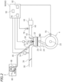
FIG. 2 is a conceptual diagram representing an internal combustion engine, various sensors, and an ECU. -
FIG. 3 is a block diagram of a determination device. -
FIG. 4(a) is a graph showing the relationship between the elapsed time and the engine rotation speed.FIG. 4(b) is a graph showing the relationship between the elapsed time and the air-fuel ratio.FIG. 4(c) is a graph showing the relationship between the elapsed time and the output value of the O2 sensor.FIG. 4(d) is a graph showing the relationship between the elapsed time and the accumulated time over which the air-fuel ratio is detected to be equal to or greater than the first threshold value.FIG. 4(e) is a time chart representing the time interval B. -
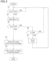
FIG. 5 is a flow chart of the first determination method. -
FIG. 6 is a graph representing the fluctuation value of the engine rotation speed when the motorcycle has fuel shortage while running. -
FIG. 7 is a flow chart of the second determination method. -
FIG. 8 is a flow chart of the third determination method. -
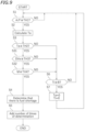
FIG. 9 is a flow chart of the fourth determination method. -
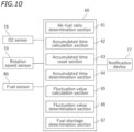
FIG. 10 is a block diagram of a determination device according to a variation. -
FIG. 11 is a flow chart of a determination method according to a variation. - An embodiment of a fuel shortage detection device for an internal combustion engine and a straddled vehicle will be described with reference to the drawings.
FIG. 1 is a side view of amotorcycle 1, which is an example of the straddled vehicle. - The
motorcycle 1 includes avehicle body frame 6 having ahead pipe 6A, an internal combustion engine (hereinafter referred to as an engine) 4, afuel tank 2, aseat 3, afront wheel 8, and arear wheel 10. Theengine 4, thefuel tank 2 and theseat 3 are supported on thevehicle body frame 6. A steering shaft (not shown) is rotatably supported on thehead pipe 6A. Ahandle bar 12 is fixed to the steering shaft. A front fork 7 is fixed to the steering shaft. Thefront wheel 8 is linked to the lower end portion of the front fork 7. Therear wheel 10 is a driving wheel that is driven by theengine 4. Theengine 4 and therear wheel 10 are linked together so that power can be transmitted therebetween by achain 5. Thechain 5 is an example of a power transmission mechanism that transmits the power of theengine 4 to therear wheel 10. Alternatively the power transmission mechanism may be a drive shaft or a transmission belt, etc. Arear arm 9 is pivotally supported on thevehicle body frame 6. Therear wheel 10 is linked to the rear end portion of therear arm 9. - As shown in
FIG. 2 , theengine 4 includes acylinder 21, apiston 22 arranged in thecylinder 21, a connectingrod 24 connected to thepiston 22, and acrank shaft 23 connected to the connectingrod 24. Theengine 4 includes acombustion chamber 25, anignition device 50, anintake valve 32, and anexhaust valve 42. Anintake passage 30 including an intake pipe, or the like, and anexhaust passage 40 including an exhaust pipe, or the like, are connected to theengine 4. Athrottle valve 34 is arranged in theintake passage 30. Acatalyst 44 is arranged in theexhaust passage 40. - A
fuel pump 48 is arranged in thefuel tank 2. Afuel injection valve 52 is attached to theintake passage 30. Thefuel pump 48 and afuel injection valve 52 are connected together by afuel pipe 46. - The
fuel tank 2 is provided with afuel sensor 80 that detects whether the amount of fuel is less than or equal to a predetermined threshold value. Theintake passage 30 is provided with apressure sensor 74. Theengine 4 includes arotation speed sensor 70 that detects the rotation speed of the crank shaft 23 (hereinafter referred to as the engine rotation speed). Theexhaust passage 40 is provided with anO2 sensor 78 that detects the oxygen concentration. - The
motorcycle 1 includes an ECU (Electronic Control Unit) 90, which is a computer. TheECU 90 includes aCPU 91, aROM 92, and aRAM 93. TheECU 90 controls theengine 4. In the present embodiment, theECU 90 functions also as adetermination device 60 that determines that theengine 4 has fuel shortage. -
FIG. 3 is a block diagram of thedetermination device 60. Thedetermination device 60 is communicably connected to theO2 sensor 78, therotation speed sensor 70, and thefuel sensor 80. Thedetermination device 60 is configured to obtain the air-fuel ratio of the gas flowing in the exhaust passage 40 (hereinafter referred to as exhaust gas) by receiving a signal from theO2 sensor 78. Thedetermination device 60 is configured to obtain the engine rotation speed by receiving a signal from therotation speed sensor 70. Thedetermination device 60 is configured to obtain the amount of fuel (hereinafter referred to simply as fuel amount) stored in thefuel tank 2 by receiving a signal from thefuel sensor 80. - The
determination device 60 includes an air-fuelratio determination section 61, an accumulatedtime calculation section 62, an accumulatedtime reset section 63, an accumulatedtime determination section 64, a fluctuationvalue calculation section 65, a fluctuationvalue determination section 66, and a fuelshortage determination section 67 by executing a computer program stored in theROM 92, or the like. Thedetermination device 60 also includes a fuel shortagecount storage section 68, which is a nonvolatile memory. The air-fuelratio determination section 61 determines whether the air-fuel ratio A/F of the exhaust gas is equal to or greater than a predetermined threshold value (hereinafter referred to as the first threshold value) TH1 based on the detection result of theO2 sensor 78. The accumulatedtime calculation section 62 calculates the accumulated time Ta of the time over which the air-fuel ratio A/F is determined to be equal to or greater than the first threshold value TH1. The accumulatedtime reset section 63 resets the accumulated time Ta (that is, sets the accumulated time Ta to zero) accumulated by the accumulatedtime calculation section 62 at every predetermined time interval B. The accumulatedtime determination section 64 determines whether the accumulated time Ta is equal to or greater than a predetermined threshold value (hereinafter referred to as second threshold value) TH2. The fluctuationvalue calculation section 65 calculates the fluctuation value DVe of the engine rotation speed. The fluctuationvalue determination section 66 determines whether the fluctuation value DVe of the engine rotation speed is equal to or greater than a predetermined threshold value (hereinafter referred to as third threshold value) TH3. The fuelshortage determination section 67 determines that there is fuel shortage when a predetermined determination condition is met. The fuel shortagecount storage section 68 stores the number of times fuel shortage has been determined. -
FIG. 4(a) to FIG. 4(d) are graphs showing changes in parameters when fuel shortage occurs while themotorcycle 1 is running. The horizontal axis of each graph represents the elapsed time T.FIG. 4(a) is a graph representing the relationship between the elapsed time T and the engine rotation speed Ve.FIG. 4(b) is a graph representing the relationship between the elapsed time T and the air-fuel ratio A/F.FIG. 4(c) is a graph representing the relationship between the elapsed time T and the output value S of theO2 sensor 78. Here, the air-fuel ratio A/F is regarded as being equal to or greater than the first threshold value TH1 when the output value S of theO2 sensor 78 is less than or equal to the threshold value S1.FIG. 4(d) is a graph representing the relationship between the elapsed time T and the accumulated time Ta over which the air-fuel ratio A/F is detected to be equal to or greater than the first threshold value TH1.FIG. 4(e) represents the time interval B. - In the example shown in
FIG. 4(a) to FIG. 4(d) , at T=T1, the air-fuel ratio A/F is equal to or greater than the first threshold value TH1, and the exhaust gas is in the lean state (seeFIG. 4(b) ). In the lean state, the engine rotation speed Ve decreases (seeFIG. 4(a) ). As shown inFIG. 4(c) , the output value S of theO2 sensor 78 may fluctuate even before fuel shortage occurs, and the output value S of theO2 sensor 78 may temporarily be less than or equal to the threshold value S1 indicating that the engine is in the lean state. Note however that it is not actually the lean state (seeFIG. 4(b) ), the state in which the output value S of theO2 sensor 78 is less than or equal to the threshold value S1 does not continue for a long period of time. Therefore, the accumulated time Ta increases little by little, but will not be equal to or greater than the second threshold value TH2 during the limited time interval B (seeFIG. 4(d) ). On the other hand, when fuel shortage actually occurs and the lean state occurs, the output value S of theO2 sensor 78 remains less than or equal to the threshold value S1. Therefore, the accumulated time Ta becomes equal to or greater than the second threshold value TH2 during the time interval B. In the example shown inFIG. 4(d) , the accumulated time Ta becomes the second threshold value TH2 when T=T2. - Therefore, in the present embodiment, the fuel
shortage determination section 67 determines, as at least one of the determination conditions, whether the accumulated time Ta has become equal to or greater than the second threshold value TH2 during the time interval B. The fuelshortage determination section 67 determines that there is fuel shortage when at least the accumulated time Ta becomes equal to or greater than the second threshold value TH2. Next, some examples of the determination method performed by thedetermination section 60 will be described. -
FIG. 5 is a flow chart of the first determination method. In the first determination method, in step S1, the air-fuelratio determination section 61 determines whether the air-fuel ratio A/F is equal to or greater than the first threshold value TH1. If the air-fuel ratio A/F is equal to or greater than the first threshold value TH1, the process proceeds step S2, and if the air-fuel ratio A/F is less than the first threshold value TH1, the process returns to step S1. In step S2, the accumulated time Ta is calculated by the accumulatedtime calculation section 62. Then, the process proceeds to step S3, and the accumulatedtime determination section 64 determines whether the accumulated time Ta is equal to or greater than the second threshold value TH2. If the accumulated time Ta is determined to be equal to or greater than the second threshold value TH2, the process proceeds to step S4, and if the accumulated time Ta is determined to be less than the second threshold value TH2, the process proceeds to step S6. When the process proceeds to step S4, it is determined by the fuelshortage determination section 67 that there is fuel shortage. Thereafter, in step S5, the number of times fuel shortage has been determined is added to the fuel shortagecount storage section 68. Note that the count stored in the fuel shortage count storage section 68 (the number of times fuel shortage has been determined) can be transferred as diagnostic data by a service person, or the like, connecting a service tool to the on-board diagnostic device (OBD). In step S6, it is determined whether the count time Ti has become equal to or greater than the time interval B. If it is determined that the count time Ti is equal to or greater than the time interval B, the accumulated time Ta and the count time Ti are reset in step S7, and the process returns to step S1. That is, the accumulated time Ta and the count time Ti are reset to zero, and the process returns to step S1. If it is determined in step S6 that the count time Ti is less than the time interval B, the process returns to step S1. - As described above, even when there is no fuel shortage, the output value S of the
O2 sensor 78 may temporarily be less than or equal to the threshold value S1. There may be cases where even if there is no fuel shortage, it is temporarily considered to be the lean state. Therefore, if fuel shortage is determined based only on the output value S of theO2 sensor 78, there may occur false determination. On the other hand, if there is no fuel shortage, the state considered to be the lean state will not last long, but if there is fuel shortage, the state considered to be the lean state will last long. According to the determination method described above, fuel shortage is determined based on the accumulated time Ta of the state considered to be the lean state (that is, the state in which the air-fuel ratio A/F is equal to or greater than the first threshold value TH1 based on the detection result of the O2 sensor 78). Therefore, it is possible to suppress the influence of a temporary lean state caused by causes other than fuel shortage. Therefore, it is possible to improve the fuel shortage detection accuracy. -
FIG. 6 is a graph representing the fluctuation value DVe of the engine rotation speed when fuel shortage occurs while themotorcycle 1 is running. Note that the fluctuation value DVe of the engine rotation speed is DVe=Ve1-Ve2, where Ve1 and Ve2 are the engine rotation speeds before and after a fluctuation for a predetermined period of time, respectively. As shown inFIG. 6 , when the lean state is reached at T=T1, the fluctuation value DVe of the engine rotation speed becomes equal to or greater than the threshold value (hereinafter referred to as the third threshold value) TH3. In the second determination method, fuel shortage is determined based on the fluctuation value DVe of the engine rotation speed, in addition to the accumulated time Ta described above. -
FIG. 7 is a flow chart of the second determination method. Also in the second determination method, as in the first determination method, steps S1 to S7 described above are performed. Note however that in the second determination method, if it is determined in step S3 that the accumulated time Ta is equal to or greater than the second threshold value TH2, the process proceeds to step S31, and it is further determined by the fuelshortage determination section 67 whether the fluctuation value DVe of the engine rotation speed equal to or greater than the third threshold value TH3. If the fluctuation value DVe of the engine rotation speed is determined to be equal to or greater than the third threshold value TH3, the process proceeds to step S4, in which it is determined by the fuelshortage determination section 67 that there is fuel shortage. If it is determined in step S31 that the fluctuation value DVe of the engine rotation speed is less than the third threshold value TH3, the process proceeds to step S6. Alternatively to the example as explained with regard to the order of processes of step S3 and step S31, Step S31 may be performed before step S3 or may be performed simultaneously with step S3. - As described above, according to the second determination method, fuel shortage is determined based on both the accumulated time Ta of the lean state and the fluctuation value DVe of the engine rotation speed. Since the fluctuation of the engine rotation speed is also taken into account, false determination is less likely to occur. Therefore, it is possible to further improve the fuel shortage detection accuracy.
- As described above, the
fuel sensor 80 detects whether the fuel amount in thefuel tank 2 is less than or equal to a threshold value. In the present embodiment, the threshold value is not zero, but is set to a predetermined value as the fuel amount that allows themotorcycle 1 to travel a predetermined distance, so that the passenger can be warned beforefuel tank 2 becomes empty. This threshold value will be hereinafter referred to as the fourth threshold value TH4. If the fuel amount M in the fuel tank 2 (hereinafter simply referred to as fuel amount) is greater than the fourth threshold value TH4, no fuel shortage occurs. In the third determination method, fuel shortage is determined based on the detection result of thefuel sensor 80, in addition to the accumulated time Ta described above. -
FIG. 8 is a flow chart of the third determination method. Also in the third determination method, as in the first determination method, steps S1 to S7 described above are performed. Note however that in the third determination method, if it is determined in step S3 that the accumulated time Ta is equal to or greater than the second threshold value TH2, the process proceeds to step S32, and the fuelshortage determination section 67 receives a signal from thefuel sensor 80 to determine whether the fuel amount M is less than or equal to the fourth threshold value TH4. If the fuel amount M is determined to be less than or equal to the fourth threshold value TH4, the process proceeds to step S4, in which the fuelshortage determination section 67 determines that there is fuel shortage. If it is determined in step S32 that the fuel amount M is greater than the fourth threshold value TH4, the process proceeds to step S6. Alternatively to the example as explained with regard to the order of processes of steps S3 and step S32. Step S32 may be performed before step S3 or may be performed simultaneously with step S3. - According to the third determination method, fuel shortage is determined based on both the accumulated time Ta of the lean state and the fuel amount M in the
fuel tank 2. Since the fuel amount M in thefuel tank 2 is also taken into account, false determination is less likely to occur. Therefore, it is possible to further improve the fuel shortage detection accuracy. - Note that the fuel shortage determination method using the
fuel sensor 80 may be selectable from amongMethods 1 to 3 below, for example. - Method 1: Based on the resistance value of the
fuel sensor 80, fuel shortage is determined when threshold value A ≤ resistance value. - Method 2: After it is determined by
Method 1 that there is fuel shortage, the period of time from when threshold value A > resistance value is reached by refueling until a certain distance is traveled is determined to be fuel shortage. - Method 3: After it is determined by
Method 1 that there is fuel shortage, the distance traveled after the determination is made is accumulated from zero, and fuel shortage is determined when threshold value B ≤ cumulative distance ≤ threshold value C is satisfied for the cumulative distance. -
FIG. 9 is a flow chart of the fourth determination method. In the fourth determination method, fuel shortage is determined based on the accumulated time Ta, the fluctuation value DVe of the engine rotation speed, and the detection result of thefuel sensor 80. Also in the fourth determination method, as in the first determination method, steps S1 to S7 described above are performed. Note however that in the fourth determination method, if it is determined in step S3 that the accumulated time Ta is equal to or greater than the second threshold value TH2, the process proceeds to step S31, and it is further determined by the fuelshortage determination section 67 whether the fluctuation value DVe of the engine rotation speed is equal to or greater than the third threshold value TH3. If the fluctuation value DVe of the engine rotation speed is determined to be equal to or greater than the third threshold value TH3, the process proceeds to step S32, and the fuelshortage determination section 67 receives a signal from thefuel sensor 80 to determine whether the fuel amount M is less than or equal to the fourth threshold value TH4. If the fuel amount M is determined to be less than or equal to the fourth threshold value TH4, the process proceeds to step S4, in which the fuelshortage determination section 67 determines that there is fuel shortage. If it is determined in step S31 that the fluctuation value DVe of the engine rotation speed is less than the third threshold value TH3, or if it is determined in step S32 that the fuel amount M is greater than the fourth threshold value TH4, the process proceeds step S6. Alternatively to the example as explained with regard to the order of processes of step S3, step S31 and step S32 another order may be taken. - As described above, according to the fourth determination method, fuel shortage is determined based on the accumulated time Ta of the lean state, the fluctuation value DVe of the engine rotation speed, and the fuel amount M in the
fuel tank 2. Since not only the accumulated time Ta of the lean state, but also the fluctuation of the engine rotation speed and the fuel amount in thefuel tank 2 are taken into account, false determination is less likely to occur. Therefore, it is possible to further improve the fuel shortage detection accuracy. - The fuel shortage detection device and the straddled vehicle according to one embodiment have been described above. The present teaching is also applicable to other embodiments.
- The
determination device 60 is theECU 90 that controls theengine 4 in the embodiment described above. Alternatively, thedetermination device 60 may be separate from theECU 90. Thedetermination device 60 may be a computer separate from theECU 90. - The number of times fuel shortage is determined is stored in the fuel shortage
count storage section 68 when it is determined by the fuelshortage determination section 67 that there is fuel shortage in the embodiment described above. In addition thereto or alternatively, when fuel shortage is determined, the passenger, etc., may be notified of fuel shortage. As shown inFIG. 10 , themotorcycle 1 may include anotification device 77 that can communicate with thedetermination device 60. The first to fourth determination methods described above may include step S51 in which thenotification device 77 notifies the passenger, etc., of fuel shortage, instead of step S5 described above (seeFIG. 11 ). Moreover, thenotification device 77 may, for example, notify the passenger by lighting a warning lamp, displaying information on a display device, or outputting audio from a speaker, etc. - A straddled vehicle refers to a vehicle that is straddled by a passenger. The straddled vehicle may be the
motorcycle 1. Alternatively, the straddled vehicle may be an auto tricycle, an ATV (All Terrain Vehicle), or a snowmobile, for example. - 1: Automobile (straddled vehicle), 4: Internal combustion engine, 5: Chain (power transmission mechanism), 10: Rear wheel (driving wheel), 40: Exhaust passage, 60: Determination device, 61: Air-fuel ratio determination section, 62: Accumulated time calculation section, 63: Accumulated time reset section, 64: Accumulated time determination section, 65: Fluctuation value calculation section, 66: Fluctuation value determination section, 67: Fuel shortage determination section, 70: Rotation speed sensor, 78: O2 sensor, 80: Fuel sensor
Claims (10)
- A fuel shortage detection device for an internal combustion engine (4), comprising:an O2 sensor (78) arranged in an exhaust passage (40) of the internal combustion engine (4) and configured to detect an oxygen concentration of a gas flowing in the exhaust passage (40); anda determination device (60) connected to the O2 sensor (78),wherein the determination device (60) includes:an air-fuel ratio determination section (61) configured to determine whether an air-fuel ratio of the gas is equal to or greater than a first threshold value (TH1) based on a detection result of the O2 sensor (78);an accumulated time calculation section (62) configured to calculate an accumulated time, which is an amount of time over which the air-fuel ratio of the gas is determined to be equal to or greater than the first threshold value (TH1) by the air-fuel ratio determination section (61);an accumulated time reset section (63) configured to reset the accumulated time calculated by the accumulated time calculation section (62) at every predetermined time interval (B);an accumulated time determination section (64) configured to determine whether the accumulated time is equal to or greater than a predetermined second threshold value (TH2); anda fuel shortage determination section (67) configured to determine that there is fuel shortage when the accumulated time becomes equal to or greater than the second threshold value (TH2).
- The fuel shortage detection device for an internal combustion engine (4) according to claim 1, comprising:a rotation speed sensor (70) connected to the determination device (60) andconfigured to detect a rotation speed of the internal combustion engine (4),wherein the determination device (60) includes:a fluctuation value calculation section (65) configured to calculate a fluctuation value of the rotation speed of the internal combustion engine (4); anda fluctuation value determination section (66) configured to determine whether the fluctuation value of the rotation speed of the internal combustion engine (4) is equal to or greater than a predetermined third threshold value (TH3),wherein the fuel shortage determination section (67) is configured to determine that there is fuel shortage when the accumulated time is equal to or greater than the second threshold value (TH2) and the fluctuation value of the rotation speed of the internal combustion engine (4) is equal to or greater than the third threshold value (TH3).
- The fuel shortage detection device for an internal combustion engine (4) according to claim 1, comprising:a fuel sensor (80) connected to the determination device (60) and configured to detect whether an amount of fuel stored in a fuel tank (2) is less than or equal to a predetermined fourth threshold value (TH4),wherein the fuel shortage determination section (67) is configured to determine that there is fuel shortage when the accumulated time is equal to or greater than the second threshold value (TH2) and the amount of fuel stored in the fuel tank (2) is less than or equal to the fourth threshold value (TH4).
- The fuel shortage detection device for an internal combustion engine (4) according to claim 1, comprising:a rotation speed sensor (70) connected to the determination device (60) and configured to detect a rotation speed of the internal combustion engine (4); anda fuel sensor (80) connected to the determination device (60) and configured to detect whether an amount of fuel stored in a fuel tank (2) is less than or equal to a predetermined fourth threshold value (TH4),wherein the determination device (60) includes:a fluctuation value calculation section (65) configured to calculate a fluctuation value of the rotation speed of the internal combustion engine (4); anda fluctuation value determination section (66) configured to determine whether the fluctuation value of the rotation speed of the internal combustion engine (4) is equal to or greater than a predetermined third threshold value (TH3),wherein the fuel shortage determination section (67) is configured to determine that there is fuel shortage when the accumulated time is equal to or greater than the second threshold value (TH2), the fluctuation value of the rotation speed of the internal combustion engine (4) is equal to or greater than the third threshold value (TH3), and the amount of fuel stored in the fuel tank (2) is less than or equal to the fourth threshold value (TH4).
- The fuel shortage detection device for an internal combustion engine (4) according to at least one of the claims 1 to 4, wherein the determination device (60) is a computer.
- A straddled vehicle comprising:an internal combustion engine (4);a driving wheel (10);a power transmission mechanism (5) that connects together the internal combustion engine (4) and the driving wheel (10); andthe fuel shortage detection device for an internal combustion engine (4) according to any one of claims 1 to 5.
- A fuel shortage detection method for an internal combustion engine (4), comprising the steps of:detecting an oxygen concentration of a gas flowing in an exhaust passage (40) of the internal combustion engine (4),determining whether an air-fuel ratio of the gas is equal to or greater than a predetermined first threshold value (TH1);calculating an accumulated time, which is an amount of time over which the air-fuel ratio of the gas is determined to be equal to or greater than the first threshold value (TH1) by the air-fuel ratio determination step;resetting the accumulated time calculated by the accumulated time calculation step at every predetermined time interval (B);determining whether the accumulated time is equal to or greater than a predetermined second threshold value (TH2); anddetermining that there is fuel shortage when the accumulated time becomes equal to or greater than the second threshold value (TH2).
- The fuel shortage detection method for an internal combustion engine (4) according to claim 7, comprising:detecting a rotation speed of the internal combustion engine (4),calculating a fluctuation value of the rotation speed of the internal combustion engine (4);determining whether the fluctuation value of the rotation speed of the internal combustion engine (4) is equal to or greater than a predetermined third threshold value (TH3), anddetermining that there is fuel shortage when the accumulated time is equal to or greater than the second threshold value (TH2) and the fluctuation value of the rotation speed of the internal combustion engine (4) is equal to or greater than the third threshold value (TH3).
- The fuel shortage detection method for an internal combustion engine (4) according to claim 7, comprising:detecting an amount of fuel stored in a fuel tank (2),determining whether the amount of fuel stored in the fuel tank (2) is less than or equal to a predetermined fourth threshold value (TH4), anddetermining that there is fuel shortage when the accumulated time is equal to or greater than the second threshold value (TH2) and the amount of fuel stored in the fuel tank (2) is less than or equal to the fourth threshold value (TH4).
- The fuel shortage detection method for an internal combustion engine (4) according to claim 7, comprising:detecting a rotation speed of the internal combustion engine (4),calculating a fluctuation value of the rotation speed of the internal combustion engine (4);determining whether the fluctuation value of the rotation speed of the internal combustion engine (4) is equal to or greater than a predetermined third threshold value (TH3);detecting an amount of fuel stored in a fuel tank (2),determining whether the amount of fuel stored in the fuel tank (2) is less than or equal to a predetermined fourth threshold value (TH4), anddetermining that there is fuel shortage when the accumulated time is equal to or greater than the second threshold value (TH2), the fluctuation value of the rotation speed of the internal combustion engine (4) is equal to or greater than the third threshold value (TH3), and the amount of fuel stored in the fuel tank (2) is less than or equal to the fourth threshold value (TH4).
Applications Claiming Priority (1)
| Application Number | Priority Date | Filing Date | Title |
|---|---|---|---|
| JP2023135369A JP2025030245A (en) | 2023-08-23 | 2023-08-23 | Fuel shortage detection device for internal combustion engine and saddle-type vehicle |
Publications (2)
| Publication Number | Publication Date |
|---|---|
| EP4517078A1 true EP4517078A1 (en) | 2025-03-05 |
| EP4517078B1 EP4517078B1 (en) | 2025-11-05 |
Family
ID=92171991
Family Applications (1)
| Application Number | Title | Priority Date | Filing Date |
|---|---|---|---|
| EP24192092.5A Active EP4517078B1 (en) | 2023-08-23 | 2024-07-31 | Fuel shortage detection device for internal combustion engine, straddled vehicle, and fuel shortage detection method for internal combustion engine |
Country Status (3)
| Country | Link |
|---|---|
| EP (1) | EP4517078B1 (en) |
| JP (1) | JP2025030245A (en) |
| TW (1) | TWI903624B (en) |
Citations (3)
| Publication number | Priority date | Publication date | Assignee | Title |
|---|---|---|---|---|
| US9810132B2 (en) * | 2015-02-27 | 2017-11-07 | Subaru Corporation | Catalyst deterioration diagnosis apparatus |
| JP2018025158A (en) | 2016-08-10 | 2018-02-15 | 株式会社Subaru | Engine control device |
| US20220120252A1 (en) * | 2020-10-16 | 2022-04-21 | Toyota Jidosha Kabushiki Kaisha | Control apparatus for internal combustion engine |
Family Cites Families (1)
| Publication number | Priority date | Publication date | Assignee | Title |
|---|---|---|---|---|
| JP5086228B2 (en) * | 2008-01-31 | 2012-11-28 | 本田技研工業株式会社 | Operation control device for internal combustion engine |
-
2023
- 2023-08-23 JP JP2023135369A patent/JP2025030245A/en active Pending
-
2024
- 2024-07-08 TW TW113125456A patent/TWI903624B/en active
- 2024-07-31 EP EP24192092.5A patent/EP4517078B1/en active Active
Patent Citations (3)
| Publication number | Priority date | Publication date | Assignee | Title |
|---|---|---|---|---|
| US9810132B2 (en) * | 2015-02-27 | 2017-11-07 | Subaru Corporation | Catalyst deterioration diagnosis apparatus |
| JP2018025158A (en) | 2016-08-10 | 2018-02-15 | 株式会社Subaru | Engine control device |
| US20220120252A1 (en) * | 2020-10-16 | 2022-04-21 | Toyota Jidosha Kabushiki Kaisha | Control apparatus for internal combustion engine |
Also Published As
| Publication number | Publication date |
|---|---|
| TWI903624B (en) | 2025-11-01 |
| EP4517078B1 (en) | 2025-11-05 |
| TW202509345A (en) | 2025-03-01 |
| JP2025030245A (en) | 2025-03-07 |
Similar Documents
| Publication | Publication Date | Title |
|---|---|---|
| US7954364B2 (en) | Malfunction diagnosis apparatus for exhaust gas sensor and method for diagnosis | |
| US5485374A (en) | Combustion-conditon diagnostic system and method for a multicylinder engine | |
| JP4487745B2 (en) | Sensor response characteristic detector | |
| JP4831015B2 (en) | Abnormality diagnosis device for internal combustion engine | |
| US20070227124A1 (en) | Deterioration diagnosis system for exhaust gas sensor | |
| JPH0771233A (en) | How to test the function of the exhaust gas catalyst | |
| US7140356B2 (en) | Engine throttle opening degree area estimation method, as well as engine acceleration detection method and device and engine fuel injection control method and device using the estimation method | |
| US20190226383A1 (en) | Method and device for emission monitoring of a combustion engine in a motor vehicle | |
| JP6286236B2 (en) | Engine system abnormality determination device | |
| WO2021181599A1 (en) | Saddle-riding-type vehicle | |
| EP4517078B1 (en) | Fuel shortage detection device for internal combustion engine, straddled vehicle, and fuel shortage detection method for internal combustion engine | |
| KR100962875B1 (en) | Apparatus and method for diagnosing degradation of catalyst for internal combustion engine | |
| US11869287B2 (en) | Abnormality detection device for exhaust gas sensor | |
| JP2010163932A (en) | Catalyst degradation diagnostic device for internal combustion engine | |
| US20130173141A1 (en) | Acceleration shock reduction control device, and method and program product for controlling acceleration shock reduction | |
| US20120010773A1 (en) | Driving diagnosis apparatus and program for same | |
| US7926466B2 (en) | Engine control device, engine control method, and motorcycle | |
| CN116761931A (en) | exhaust monitoring system | |
| JP2000291485A (en) | Engine misfire detection device | |
| JP4422563B2 (en) | Engine combustion state diagnostic device | |
| JP3323733B2 (en) | Air-fuel ratio learning control method when traveling downhill | |
| JP2003049694A (en) | Atmospheric pressure estimation method for internal combustion engine and control device for internal combustion engine | |
| JPH05202799A (en) | Combustion condition diagnostic device of internal combustion engine | |
| JP2008069708A (en) | Exhaust gas state estimation device | |
| KR100774313B1 (en) | Diagnosis method of car oxygen sensor |
Legal Events
| Date | Code | Title | Description |
|---|---|---|---|
| PUAI | Public reference made under article 153(3) epc to a published international application that has entered the european phase |
Free format text: ORIGINAL CODE: 0009012 |
|
| STAA | Information on the status of an ep patent application or granted ep patent |
Free format text: STATUS: THE APPLICATION HAS BEEN PUBLISHED |
|
| AK | Designated contracting states |
Kind code of ref document: A1 Designated state(s): AL AT BE BG CH CY CZ DE DK EE ES FI FR GB GR HR HU IE IS IT LI LT LU LV MC ME MK MT NL NO PL PT RO RS SE SI SK SM TR |
|
| STAA | Information on the status of an ep patent application or granted ep patent |
Free format text: STATUS: REQUEST FOR EXAMINATION WAS MADE |
|
| 17P | Request for examination filed |
Effective date: 20250311 |
|
| GRAP | Despatch of communication of intention to grant a patent |
Free format text: ORIGINAL CODE: EPIDOSNIGR1 |
|
| STAA | Information on the status of an ep patent application or granted ep patent |
Free format text: STATUS: GRANT OF PATENT IS INTENDED |
|
| INTG | Intention to grant announced |
Effective date: 20250618 |
|
| P01 | Opt-out of the competence of the unified patent court (upc) registered |
Free format text: CASE NUMBER: UPC_APP_1587_4517078/2025 Effective date: 20250731 |
|
| GRAS | Grant fee paid |
Free format text: ORIGINAL CODE: EPIDOSNIGR3 |
|
| GRAA | (expected) grant |
Free format text: ORIGINAL CODE: 0009210 |
|
| STAA | Information on the status of an ep patent application or granted ep patent |
Free format text: STATUS: THE PATENT HAS BEEN GRANTED |
|
| AK | Designated contracting states |
Kind code of ref document: B1 Designated state(s): AL AT BE BG CH CY CZ DE DK EE ES FI FR GB GR HR HU IE IS IT LI LT LU LV MC ME MK MT NL NO PL PT RO RS SE SI SK SM TR |
|
| REG | Reference to a national code |
Ref country code: CH Ref legal event code: F10 Free format text: ST27 STATUS EVENT CODE: U-0-0-F10-F00 (AS PROVIDED BY THE NATIONAL OFFICE) Effective date: 20251105 Ref country code: GB Ref legal event code: FG4D |
|
| REG | Reference to a national code |
Ref country code: DE Ref legal event code: R096 Ref document number: 602024001177 Country of ref document: DE |
|
| REG | Reference to a national code |
Ref country code: IE Ref legal event code: FG4D |
|
| REG | Reference to a national code |
Ref country code: NL Ref legal event code: MP Effective date: 20251105 |
|
| PG25 | Lapsed in a contracting state [announced via postgrant information from national office to epo] |
Ref country code: ES Free format text: LAPSE BECAUSE OF FAILURE TO SUBMIT A TRANSLATION OF THE DESCRIPTION OR TO PAY THE FEE WITHIN THE PRESCRIBED TIME-LIMIT Effective date: 20251105 |
|
| REG | Reference to a national code |
Ref country code: LT Ref legal event code: MG9D |
|
| PG25 | Lapsed in a contracting state [announced via postgrant information from national office to epo] |
Ref country code: NO Free format text: LAPSE BECAUSE OF FAILURE TO SUBMIT A TRANSLATION OF THE DESCRIPTION OR TO PAY THE FEE WITHIN THE PRESCRIBED TIME-LIMIT Effective date: 20260205 |
|
| PG25 | Lapsed in a contracting state [announced via postgrant information from national office to epo] |
Ref country code: AT Free format text: LAPSE BECAUSE OF FAILURE TO SUBMIT A TRANSLATION OF THE DESCRIPTION OR TO PAY THE FEE WITHIN THE PRESCRIBED TIME-LIMIT Effective date: 20251105 Ref country code: FI Free format text: LAPSE BECAUSE OF FAILURE TO SUBMIT A TRANSLATION OF THE DESCRIPTION OR TO PAY THE FEE WITHIN THE PRESCRIBED TIME-LIMIT Effective date: 20251105 Ref country code: HR Free format text: LAPSE BECAUSE OF FAILURE TO SUBMIT A TRANSLATION OF THE DESCRIPTION OR TO PAY THE FEE WITHIN THE PRESCRIBED TIME-LIMIT Effective date: 20251105 |
|
| REG | Reference to a national code |
Ref country code: AT Ref legal event code: MK05 Ref document number: 1854567 Country of ref document: AT Kind code of ref document: T Effective date: 20251105 |
|
| PG25 | Lapsed in a contracting state [announced via postgrant information from national office to epo] |
Ref country code: NL Free format text: LAPSE BECAUSE OF FAILURE TO SUBMIT A TRANSLATION OF THE DESCRIPTION OR TO PAY THE FEE WITHIN THE PRESCRIBED TIME-LIMIT Effective date: 20251105 |
|
| PG25 | Lapsed in a contracting state [announced via postgrant information from national office to epo] |
Ref country code: RS Free format text: LAPSE BECAUSE OF FAILURE TO SUBMIT A TRANSLATION OF THE DESCRIPTION OR TO PAY THE FEE WITHIN THE PRESCRIBED TIME-LIMIT Effective date: 20260205 |
|
| PG25 | Lapsed in a contracting state [announced via postgrant information from national office to epo] |
Ref country code: IS Free format text: LAPSE BECAUSE OF FAILURE TO SUBMIT A TRANSLATION OF THE DESCRIPTION OR TO PAY THE FEE WITHIN THE PRESCRIBED TIME-LIMIT Effective date: 20260305 |
|
| PG25 | Lapsed in a contracting state [announced via postgrant information from national office to epo] |
Ref country code: PT Free format text: LAPSE BECAUSE OF FAILURE TO SUBMIT A TRANSLATION OF THE DESCRIPTION OR TO PAY THE FEE WITHIN THE PRESCRIBED TIME-LIMIT Effective date: 20260305 |
|
| PG25 | Lapsed in a contracting state [announced via postgrant information from national office to epo] |
Ref country code: PL Free format text: LAPSE BECAUSE OF FAILURE TO SUBMIT A TRANSLATION OF THE DESCRIPTION OR TO PAY THE FEE WITHIN THE PRESCRIBED TIME-LIMIT Effective date: 20251105 |
|
| PG25 | Lapsed in a contracting state [announced via postgrant information from national office to epo] |
Ref country code: LV Free format text: LAPSE BECAUSE OF FAILURE TO SUBMIT A TRANSLATION OF THE DESCRIPTION OR TO PAY THE FEE WITHIN THE PRESCRIBED TIME-LIMIT Effective date: 20251105 |
|
| PG25 | Lapsed in a contracting state [announced via postgrant information from national office to epo] |
Ref country code: BG Free format text: LAPSE BECAUSE OF FAILURE TO SUBMIT A TRANSLATION OF THE DESCRIPTION OR TO PAY THE FEE WITHIN THE PRESCRIBED TIME-LIMIT Effective date: 20251105 |
|
| PG25 | Lapsed in a contracting state [announced via postgrant information from national office to epo] |
Ref country code: LT Free format text: LAPSE BECAUSE OF FAILURE TO SUBMIT A TRANSLATION OF THE DESCRIPTION OR TO PAY THE FEE WITHIN THE PRESCRIBED TIME-LIMIT Effective date: 20251105 |
|
| PG25 | Lapsed in a contracting state [announced via postgrant information from national office to epo] |
Ref country code: SM Free format text: LAPSE BECAUSE OF FAILURE TO SUBMIT A TRANSLATION OF THE DESCRIPTION OR TO PAY THE FEE WITHIN THE PRESCRIBED TIME-LIMIT Effective date: 20251105 |
|
| PG25 | Lapsed in a contracting state [announced via postgrant information from national office to epo] |
Ref country code: DK Free format text: LAPSE BECAUSE OF FAILURE TO SUBMIT A TRANSLATION OF THE DESCRIPTION OR TO PAY THE FEE WITHIN THE PRESCRIBED TIME-LIMIT Effective date: 20251105 |
|
| PG25 | Lapsed in a contracting state [announced via postgrant information from national office to epo] |
Ref country code: IT Free format text: LAPSE BECAUSE OF FAILURE TO SUBMIT A TRANSLATION OF THE DESCRIPTION OR TO PAY THE FEE WITHIN THE PRESCRIBED TIME-LIMIT Effective date: 20251105 |
|
| PG25 | Lapsed in a contracting state [announced via postgrant information from national office to epo] |
Ref country code: EE Free format text: LAPSE BECAUSE OF FAILURE TO SUBMIT A TRANSLATION OF THE DESCRIPTION OR TO PAY THE FEE WITHIN THE PRESCRIBED TIME-LIMIT Effective date: 20251105 |
|
| PG25 | Lapsed in a contracting state [announced via postgrant information from national office to epo] |
Ref country code: CZ Free format text: LAPSE BECAUSE OF FAILURE TO SUBMIT A TRANSLATION OF THE DESCRIPTION OR TO PAY THE FEE WITHIN THE PRESCRIBED TIME-LIMIT Effective date: 20251105 |
|
| PG25 | Lapsed in a contracting state [announced via postgrant information from national office to epo] |
Ref country code: SK Free format text: LAPSE BECAUSE OF FAILURE TO SUBMIT A TRANSLATION OF THE DESCRIPTION OR TO PAY THE FEE WITHIN THE PRESCRIBED TIME-LIMIT Effective date: 20251105 |
|
| PG25 | Lapsed in a contracting state [announced via postgrant information from national office to epo] |
Ref country code: SE Free format text: LAPSE BECAUSE OF FAILURE TO SUBMIT A TRANSLATION OF THE DESCRIPTION OR TO PAY THE FEE WITHIN THE PRESCRIBED TIME-LIMIT Effective date: 20251105 |