EP4517043A1 - Driving engine for vehicles - Google Patents
Driving engine for vehicles Download PDFInfo
- Publication number
- EP4517043A1 EP4517043A1 EP24197835.2A EP24197835A EP4517043A1 EP 4517043 A1 EP4517043 A1 EP 4517043A1 EP 24197835 A EP24197835 A EP 24197835A EP 4517043 A1 EP4517043 A1 EP 4517043A1
- Authority
- EP
- European Patent Office
- Prior art keywords
- driving engine
- width
- piston
- connecting rod
- engine according
- Prior art date
- Legal status (The legal status is an assumption and is not a legal conclusion. Google has not performed a legal analysis and makes no representation as to the accuracy of the status listed.)
- Granted
Links
Images



Classifications
-
- F—MECHANICAL ENGINEERING; LIGHTING; HEATING; WEAPONS; BLASTING
- F02—COMBUSTION ENGINES; HOT-GAS OR COMBUSTION-PRODUCT ENGINE PLANTS
- F02F—CYLINDERS, PISTONS OR CASINGS, FOR COMBUSTION ENGINES; ARRANGEMENTS OF SEALINGS IN COMBUSTION ENGINES
- F02F3/00—Pistons
- F02F3/28—Other pistons with specially-shaped head
-
- F—MECHANICAL ENGINEERING; LIGHTING; HEATING; WEAPONS; BLASTING
- F02—COMBUSTION ENGINES; HOT-GAS OR COMBUSTION-PRODUCT ENGINE PLANTS
- F02B—INTERNAL-COMBUSTION PISTON ENGINES; COMBUSTION ENGINES IN GENERAL
- F02B75/00—Other engines
- F02B75/16—Engines characterised by number of cylinders, e.g. single-cylinder engines
- F02B75/18—Multi-cylinder engines
- F02B75/22—Multi-cylinder engines with cylinders in V, fan, or star arrangement
-
- F—MECHANICAL ENGINEERING; LIGHTING; HEATING; WEAPONS; BLASTING
- F01—MACHINES OR ENGINES IN GENERAL; ENGINE PLANTS IN GENERAL; STEAM ENGINES
- F01B—MACHINES OR ENGINES, IN GENERAL OR OF POSITIVE-DISPLACEMENT TYPE, e.g. STEAM ENGINES
- F01B9/00—Reciprocating-piston machines or engines characterised by connections between pistons and main shafts, not specific to groups F01B1/00 - F01B7/00
- F01B9/02—Reciprocating-piston machines or engines characterised by connections between pistons and main shafts, not specific to groups F01B1/00 - F01B7/00 with crankshaft
-
- F—MECHANICAL ENGINEERING; LIGHTING; HEATING; WEAPONS; BLASTING
- F02—COMBUSTION ENGINES; HOT-GAS OR COMBUSTION-PRODUCT ENGINE PLANTS
- F02B—INTERNAL-COMBUSTION PISTON ENGINES; COMBUSTION ENGINES IN GENERAL
- F02B75/00—Other engines
- F02B75/32—Engines characterised by connections between pistons and main shafts and not specific to preceding main groups
-
- F—MECHANICAL ENGINEERING; LIGHTING; HEATING; WEAPONS; BLASTING
- F02—COMBUSTION ENGINES; HOT-GAS OR COMBUSTION-PRODUCT ENGINE PLANTS
- F02F—CYLINDERS, PISTONS OR CASINGS, FOR COMBUSTION ENGINES; ARRANGEMENTS OF SEALINGS IN COMBUSTION ENGINES
- F02F1/00—Cylinders; Cylinder heads
- F02F1/18—Other cylinders
-
- F—MECHANICAL ENGINEERING; LIGHTING; HEATING; WEAPONS; BLASTING
- F02—COMBUSTION ENGINES; HOT-GAS OR COMBUSTION-PRODUCT ENGINE PLANTS
- F02F—CYLINDERS, PISTONS OR CASINGS, FOR COMBUSTION ENGINES; ARRANGEMENTS OF SEALINGS IN COMBUSTION ENGINES
- F02F1/00—Cylinders; Cylinder heads
- F02F1/18—Other cylinders
- F02F1/183—Oval or square cylinders
-
- F—MECHANICAL ENGINEERING; LIGHTING; HEATING; WEAPONS; BLASTING
- F02—COMBUSTION ENGINES; HOT-GAS OR COMBUSTION-PRODUCT ENGINE PLANTS
- F02F—CYLINDERS, PISTONS OR CASINGS, FOR COMBUSTION ENGINES; ARRANGEMENTS OF SEALINGS IN COMBUSTION ENGINES
- F02F3/00—Pistons
-
- F—MECHANICAL ENGINEERING; LIGHTING; HEATING; WEAPONS; BLASTING
- F16—ENGINEERING ELEMENTS AND UNITS; GENERAL MEASURES FOR PRODUCING AND MAINTAINING EFFECTIVE FUNCTIONING OF MACHINES OR INSTALLATIONS; THERMAL INSULATION IN GENERAL
- F16J—PISTONS; CYLINDERS; SEALINGS
- F16J7/00—Piston-rods
-
- F—MECHANICAL ENGINEERING; LIGHTING; HEATING; WEAPONS; BLASTING
- F16—ENGINEERING ELEMENTS AND UNITS; GENERAL MEASURES FOR PRODUCING AND MAINTAINING EFFECTIVE FUNCTIONING OF MACHINES OR INSTALLATIONS; THERMAL INSULATION IN GENERAL
- F16C—SHAFTS; FLEXIBLE SHAFTS; ELEMENTS OR CRANKSHAFT MECHANISMS; ROTARY BODIES OTHER THAN GEARING ELEMENTS; BEARINGS
- F16C7/00—Connecting-rods or like links pivoted at both ends; Construction of connecting-rod heads
- F16C7/02—Constructions of connecting-rods with constant length
- F16C7/023—Constructions of connecting-rods with constant length for piston engines, pumps or the like
Definitions
- the present invention relates to a driving engine for vehicles.
- the present invention relates to a driving engine of the type comprising a crankshaft mounted so as to rotate around a rotation axis; at least one group of cylinders comprising, in turn, at least two cylinders aligned with one another in a direction parallel to the rotation axis of the crankshaft; a piston engaged in each cylinder in a sliding manner; and at least one connecting rod interposed between each piston and the crankshaft to convert the rectilinear reciprocating motion of the pistons along the relative cylinders into a rotational motion of the crankshaft.
- the driving engines for vehicles of known type described above have some drawbacks, mainly deriving from the fact that the group of cylinders and of relative pistons has a relatively high longitudinal footprint, measured parallel to the rotation axis of the crankshaft.
- the object of the present invention is to provide a driving engine for vehicles without the drawbacks set forth above and which is simple and inexpensive to produce.
- the reference number 1 indicates, as a whole, a driving engine for vehicles comprising, in this case, twelve cylinders 2 arranged according to two groups 3, 4 of cylinders 2 placed side by side.
- Each group 3, 4 of cylinders 2 comprises, in this case, six cylinders 2, which are aligned with one another in a direction 5, have respective longitudinal axes 6 parallel to one another, and are engaged in a sliding manner by respective pistons 7.
- the pistons 7 are moved with a rectilinear reciprocating motion along the relative cylinders 2 by the thrust generated by the chemical reaction generated by the combustion of a fuel and a comburent inside the cylinders 2.
- the reciprocating rectilinear motion of the pistons 7 along the relative cylinders 2 is converted into a rotational motion of a crankshaft 8 mounted to rotate around a rotation axis 9 parallel to the direction 5.
- the pistons 7 (hereinafter indicated with 7a) associated with the cylinders 2 (hereinafter indicated with 2a) of the group 3 of cylinders 2 are connected to the crankshaft 8 by means of the interposition of respective connecting rods 10, each of which extends between two rotation axes 11, 12 parallel to one another and to the axis 9, and of which the axis 11 is the rotation axis of the connecting rod 10 with respect to a relative connecting rod pin 8a of the crankshaft 8 and the axis 12 is the rotation axis of the connecting rod 10 with respect to the relative piston 7a.
- the pistons 7 (hereinafter indicated with 7b) associated with the cylinders 2 (hereinafter indicated with 2b) of the group 4 of cylinders 2 are connected to the crankshaft 8 by means of the interposition of respective connecting rods 13, each of which extends between two rotation axes 14, 15 parallel to one another and to the axis 9, and of which the axis 14 is the rotation axis of the connecting rod 13 with respect to a corresponding connecting rod 10 and the axis 15 is the rotation axis of the connecting rod 13 with respect to the relative piston 7b.
- each connecting rod 13 is directly coupled to the corresponding connecting rod 10, the connecting rods 10, 13 of each pair of connecting rods 10 and 13 connected to one another are substantially coplanar to one another, extend substantially in a single containment plane P, and therefore have a relatively limited footprint in the direction 5.
- Each cylinder 2a, 2b is delimited by a side wall 16 comprising two portions 17 with a semi-cylindrical shape opposite one another and two portions 18 with a flat shape opposite one another obtained between the portions 17.
- each piston 7a, 7b is delimited by a free face 19 facing the relative cylinder 2a, 2b, and is further delimited by a side wall 20 comprising two portions 21 with a semi-cylindrical shape opposite one another and two portions 22 with a flat shape opposite one another obtained between the portions 21.
- the wall 20 is undercut so as to have two cavities 23 opposite one another, which are obtained at least at the portions 22, in particular both at the portions 21, and at the portions 22, and limit the friction between the piston 7a, 7b and the relative cylinder 2a, 2b.
- the cylinders 2a, 2b and the relative pistons 7a, 7b are configured and oriented so that:
- Each piston 7a, 7b also has a plurality of recesses 25, each of which is configured to accommodate a respective elastic band, known and not illustrated, designed to couple the piston 7a, 7b and the relative cylinder 2a, 2b to one another in a fluid-tight manner.
- the driving engine 1 has some advantages mainly deriving from the fact that the groups 3, 4 of cylinders 2a, 2b have a relatively limited footprint in the direction 5 and that the cavities 23 guarantee relatively limited friction between the cylinders 2a, 2b and the relative pistons 7a, 7b.
Landscapes
- Engineering & Computer Science (AREA)
- General Engineering & Computer Science (AREA)
- Mechanical Engineering (AREA)
- Chemical & Material Sciences (AREA)
- Combustion & Propulsion (AREA)
- Transmission Devices (AREA)
- Shafts, Cranks, Connecting Bars, And Related Bearings (AREA)
Abstract
Description
- This patent application claims priority from
Italian patent application no. 102023000018096 filed on September 4, 2023 - The present invention relates to a driving engine for vehicles.
- In particular, the present invention relates to a driving engine of the type comprising a crankshaft mounted so as to rotate around a rotation axis; at least one group of cylinders comprising, in turn, at least two cylinders aligned with one another in a direction parallel to the rotation axis of the crankshaft; a piston engaged in each cylinder in a sliding manner; and at least one connecting rod interposed between each piston and the crankshaft to convert the rectilinear reciprocating motion of the pistons along the relative cylinders into a rotational motion of the crankshaft.
- As pistons have a cylindrical shape, the driving engines for vehicles of known type described above have some drawbacks, mainly deriving from the fact that the group of cylinders and of relative pistons has a relatively high longitudinal footprint, measured parallel to the rotation axis of the crankshaft.
- The object of the present invention is to provide a driving engine for vehicles without the drawbacks set forth above and which is simple and inexpensive to produce.
- According to the present invention, there is provided a driving engine for vehicles as claimed in the appended claims.
- The present invention will now be described with reference to the accompanying drawings, which illustrate a non-limiting example of embodiment thereof, wherein:
-
Fig. 1 is a schematic perspective view of a preferred embodiment of the driving engine for vehicles of the present invention; -
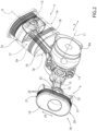
Figs. 2 and3 are two schematic perspective views, with parts removed for clarity, of a detail of the driving engine ofFig. 1 ; -
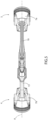
Figs. 4 and5 are two schematic side views, with parts removed for clarity, of the detail ofFigs. 2 and3 ; -
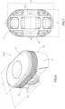
Fig. 6 is a schematic perspective view, with parts in section, of a detail ofFigs. 2 and3 ; and -
Fig. 7 is a schematic side view, with parts removed for clarity, of the detail ofFig. 6 . - With reference to
Figs. 1 ,2 ,3 ,4 , and5 , thereference number 1 indicates, as a whole, a driving engine for vehicles comprising, in this case, twelve cylinders 2 arranged according to twogroups - Each
group direction 5, have respectivelongitudinal axes 6 parallel to one another, and are engaged in a sliding manner by respective pistons 7. - The pistons 7 are moved with a rectilinear reciprocating motion along the relative cylinders 2 by the thrust generated by the chemical reaction generated by the combustion of a fuel and a comburent inside the cylinders 2.
- The reciprocating rectilinear motion of the pistons 7 along the relative cylinders 2 is converted into a rotational motion of a
crankshaft 8 mounted to rotate around arotation axis 9 parallel to thedirection 5. - The pistons 7 (hereinafter indicated with 7a) associated with the cylinders 2 (hereinafter indicated with 2a) of the
group 3 of cylinders 2 are connected to thecrankshaft 8 by means of the interposition of respective connectingrods 10, each of which extends between tworotation axes axis 9, and of which theaxis 11 is the rotation axis of the connectingrod 10 with respect to a relative connectingrod pin 8a of thecrankshaft 8 and theaxis 12 is the rotation axis of the connectingrod 10 with respect to therelative piston 7a. - The pistons 7 (hereinafter indicated with 7b) associated with the cylinders 2 (hereinafter indicated with 2b) of the
group 4 of cylinders 2 are connected to thecrankshaft 8 by means of the interposition of respective connectingrods 13, each of which extends between tworotation axes axis 9, and of which theaxis 14 is the rotation axis of the connectingrod 13 with respect to a corresponding connectingrod 10 and theaxis 15 is the rotation axis of the connectingrod 13 with respect to therelative piston 7b. - As each connecting
rod 13 is directly coupled to thecorresponding connecting rod 10, the connectingrods rods direction 5. - Each
cylinder 2a, 2b is delimited by aside wall 16 comprising twoportions 17 with a semi-cylindrical shape opposite one another and twoportions 18 with a flat shape opposite one another obtained between theportions 17. - According to what is shown in
Figs. 6 and 7 , eachpiston free face 19 facing therelative cylinder 2a, 2b, and is further delimited by aside wall 20 comprising twoportions 21 with a semi-cylindrical shape opposite one another and twoportions 22 with a flat shape opposite one another obtained between theportions 21. - The
wall 20 is undercut so as to have twocavities 23 opposite one another, which are obtained at least at theportions 22, in particular both at theportions 21, and at theportions 22, and limit the friction between thepiston relative cylinder 2a, 2b. - The
cylinders 2a, 2b and therelative pistons - each
piston direction 5, less than the maximum width L2 measured parallel to adirection 24 parallel to theface 19 of thepiston direction 5; and - each
cylinder 2a, 2b has a maximum inner width L3, measured parallel to thedirection 5, which rounds up the width L1 and a maximum inner width L4, measured parallel to thedirection 24, which rounds up the width L2 and is greater than the width L3. - Each
piston recesses 25, each of which is configured to accommodate a respective elastic band, known and not illustrated, designed to couple thepiston relative cylinder 2a, 2b to one another in a fluid-tight manner. - The
driving engine 1 has some advantages mainly deriving from the fact that thegroups cylinders 2a, 2b have a relatively limited footprint in thedirection 5 and that thecavities 23 guarantee relatively limited friction between thecylinders 2a, 2b and therelative pistons
Claims (12)
- A driving engine for vehicles comprising a crankshaft (8) mounted so as to rotate around a rotation axis (9); at least one first group (3) of cylinders (2a) comprising, in turn, at least two first cylinders (2a) aligned with one another in a first direction (5), which is parallel to the rotation axis (9) of the crankshaft (8); a first piston (7a), which is engaged in each first cylinder (2a) in a sliding manner and is delimited by a free face (19); and at least one first connecting rod (10) interposed between each first piston (7a) and the crankshaft (8); the free face (19) of each first piston (7a) having a first width (L1) measured parallel to the first direction (5) and a second width (L2) measured parallel to a second direction (24), which is transverse to the first direction (5); and characterized in that the first width (L1) of each first piston (7a) is smaller than the relative second width (L2).
- The driving engine according to claim 1 and further comprising a second group (4) of cylinders (2b) comprising, in turn, a plurality of second cylinders (2b), which are as many as the first cylinders (2a), are aligned with one another in the first direction (5) and are engaged, in a sliding manner, by respective second pistons (7b) connected to the crankshaft (8) by means of respective second connecting rods (13).
- The driving engine according to claim 2, wherein each first connecting rod (10) is engaged by the crankshaft (8) in a rotary manner and is directly coupled to a corresponding second connecting rod (13) in a rotary manner.
- The driving engine according to claim 3, wherein each first connecting rod (10) is substantially coplanar to the corresponding second connecting rod (13).
- The driving engine according to 3 or 4, wherein each second connecting rod (13) extends between two rotation axes (14, 15), one of them being the rotation axis of the second connecting rod (13) with the first connecting rod (10) and the other one being the rotation axis of the second connecting rod (13) with the second piston (7b).
- The driving engine according to any one of the claims from 2 to 5, wherein each second piston (7b) is delimited by a free face (19) having said first width (L1) measured parallel to the first direction (5) and said second width (L2) measured parallel to the second direction (24).
- The driving engine according to any one of the preceding claims, wherein each cylinder (2a, 2b) has a third width (L3) measured parallel to the first direction (5), which rounds up said first width (L1), and a fourth width (L4) measured parallel to the second direction (24), which rounds up said second width (L2) and is greater than the third width (L3).
- The driving engine according to any one of the preceding claims, wherein each piston (7a, 7b) is delimited by a side wall (20) comprising two first portions (21) opposite with one another and with a substantially semi-cylindrical shape and two second portions (22) opposite one another and with a substantially flat shape, each extending between the two first portions (21).
- The driving engine according to claim 8, wherein the side wall (20) has two cavities (23) opposite one another.
- The driving engine according to claim 9, wherein each cavity (23) is obtained in the area at least of a relative second portion (22), in particular in the area of a relative second portion (22) and of each first portion (21).
- The driving engine according to any one of the preceding claims, wherein each cylinder (2a, 2b) is delimited by a side wall (16) comprising two first portions (17) opposite with one another and with a substantially semi-cylindrical shape and two second portions (18) opposite one another and with a substantially flat shape, each extending between the two first portions (17).
- The driving engine according to any one of the preceding claims, wherein each piston (7a, 7b) has a plurality or recesses (25), each configured to accommodate a respective elastic band designed to couple the piston (7a, 7b) and the relative cylinder (2a, 2b) to one another in a fluid-tight manner.
Applications Claiming Priority (1)
| Application Number | Priority Date | Filing Date | Title |
|---|---|---|---|
| IT102023000018096A IT202300018096A1 (en) | 2023-09-04 | 2023-09-04 | VEHICLE POWERTRAIN ENGINE |
Publications (2)
| Publication Number | Publication Date |
|---|---|
| EP4517043A1 true EP4517043A1 (en) | 2025-03-05 |
| EP4517043B1 EP4517043B1 (en) | 2026-03-11 |
Family
ID=88779396
Family Applications (1)
| Application Number | Title | Priority Date | Filing Date |
|---|---|---|---|
| EP24197835.2A Active EP4517043B1 (en) | 2023-09-04 | 2024-09-02 | Driving engine for vehicles |
Country Status (4)
| Country | Link |
|---|---|
| US (1) | US12429011B2 (en) |
| EP (1) | EP4517043B1 (en) |
| CN (1) | CN119554131A (en) |
| IT (1) | IT202300018096A1 (en) |
Citations (4)
| Publication number | Priority date | Publication date | Assignee | Title |
|---|---|---|---|---|
| GB276546A (en) * | 1926-12-28 | 1927-09-01 | Samuel Gordon Nicholson | Improvements in pistons and cylinders |
| US4383508A (en) * | 1978-03-30 | 1983-05-17 | Honda Giken Kogyo Kabushiki Kaisha | Internal combustion engine |
| DE3803152A1 (en) * | 1988-02-03 | 1989-08-17 | Klaue Hermann | Reciprocating piston internal combustion engine |
| US10138807B2 (en) * | 2015-03-03 | 2018-11-27 | Z Mechanism Technology Institute Co., Ltd. | Drive device provided with XY-separating crank mechanism |
Family Cites Families (7)
| Publication number | Priority date | Publication date | Assignee | Title |
|---|---|---|---|---|
| US2409555A (en) * | 1945-02-02 | 1946-10-15 | Gadoux Eugene Marius | Piston engine |
| JPS5941316Y2 (en) * | 1978-06-26 | 1984-11-28 | 本田技研工業株式会社 | internal combustion engine piston rings |
| JPS5627047A (en) * | 1979-08-07 | 1981-03-16 | Honda Motor Co Ltd | 4-cycle engine |
| AU2010292997B2 (en) * | 2009-09-14 | 2016-09-15 | Leslie Malcolm Jones | Piston and use therefor |
| US8578895B2 (en) * | 2010-02-17 | 2013-11-12 | Primavis S.R.L. | Two-stroke engine with low consumption and low emissions |
| US8347843B1 (en) * | 2011-03-25 | 2013-01-08 | Batiz-Vergara Jose A | Piston for internal combustion engine |
| US10989138B2 (en) * | 2017-03-30 | 2021-04-27 | Quest Engines, LLC | Internal combustion engine |
-
2023
- 2023-09-04 IT IT102023000018096A patent/IT202300018096A1/en unknown
-
2024
- 2024-08-27 US US18/815,918 patent/US12429011B2/en active Active
- 2024-09-02 CN CN202411214986.2A patent/CN119554131A/en active Pending
- 2024-09-02 EP EP24197835.2A patent/EP4517043B1/en active Active
Patent Citations (4)
| Publication number | Priority date | Publication date | Assignee | Title |
|---|---|---|---|---|
| GB276546A (en) * | 1926-12-28 | 1927-09-01 | Samuel Gordon Nicholson | Improvements in pistons and cylinders |
| US4383508A (en) * | 1978-03-30 | 1983-05-17 | Honda Giken Kogyo Kabushiki Kaisha | Internal combustion engine |
| DE3803152A1 (en) * | 1988-02-03 | 1989-08-17 | Klaue Hermann | Reciprocating piston internal combustion engine |
| US10138807B2 (en) * | 2015-03-03 | 2018-11-27 | Z Mechanism Technology Institute Co., Ltd. | Drive device provided with XY-separating crank mechanism |
Also Published As
| Publication number | Publication date |
|---|---|
| EP4517043B1 (en) | 2026-03-11 |
| US12429011B2 (en) | 2025-09-30 |
| CN119554131A (en) | 2025-03-04 |
| US20250075671A1 (en) | 2025-03-06 |
| IT202300018096A1 (en) | 2025-03-04 |
Similar Documents
| Publication | Publication Date | Title |
|---|---|---|
| US7201133B2 (en) | Internal combustion engine having dual piston cylinders and linear drive arrangement | |
| US5535715A (en) | Geared reciprocating piston engine with spherical rotary valve | |
| RU2082893C1 (en) | Device for transformation of reciprocating motion into rotation and rotation into reciprocating motion | |
| EP0177214B1 (en) | Compact internal combustion engines | |
| US6321693B1 (en) | Reciprocating rotary piston system and pressure pump and internal combustion engine using the same | |
| KR20070088348A (en) | Prefabricated crankshafts, especially prefabricated crankshafts for medium speed four-cycle diesel engines | |
| US4301776A (en) | Crankshaft apparatus | |
| EP3066312B1 (en) | Internal combustion engine | |
| US4173151A (en) | Motion translating mechanism | |
| EP2021584B1 (en) | Internal combustion engine | |
| US5560327A (en) | Internal combustion engine with improved cycle dynamics | |
| JP2015503054A (en) | engine | |
| US4442758A (en) | Piston machine | |
| EP0513324B1 (en) | System for reversibly transforming rotary motion into self-guided rectilinear motion | |
| EP1937938B1 (en) | Piston cam engine | |
| US3482554A (en) | Internal combustion engine v block cam transmission | |
| EP4517043A1 (en) | Driving engine for vehicles | |
| US3536050A (en) | Motion-converting device for barrel-type machine and various applications thereof | |
| WO2002036937A1 (en) | Dual torque barrel type engine | |
| RU139346U1 (en) | MODULAR AIRCRAFT UNLOADED PISTON ENGINE | |
| US5836234A (en) | Single CAM reciprocating linked piston type engine | |
| EP3708770A1 (en) | Internal combustion engine with opposed pistons and a central drive shaft | |
| US4616604A (en) | Stator-Rotor piston internal combustion engine | |
| US6799542B2 (en) | Engine having piston-cam assembly powertrain | |
| EP0566072A1 (en) | Power transmitting device |
Legal Events
| Date | Code | Title | Description |
|---|---|---|---|
| PUAI | Public reference made under article 153(3) epc to a published international application that has entered the european phase |
Free format text: ORIGINAL CODE: 0009012 |
|
| STAA | Information on the status of an ep patent application or granted ep patent |
Free format text: STATUS: THE APPLICATION HAS BEEN PUBLISHED |
|
| AK | Designated contracting states |
Kind code of ref document: A1 Designated state(s): AL AT BE BG CH CY CZ DE DK EE ES FI FR GB GR HR HU IE IS IT LI LT LU LV MC ME MK MT NL NO PL PT RO RS SE SI SK SM TR |
|
| STAA | Information on the status of an ep patent application or granted ep patent |
Free format text: STATUS: REQUEST FOR EXAMINATION WAS MADE |
|
| 17P | Request for examination filed |
Effective date: 20250808 |
|
| RIC1 | Information provided on ipc code assigned before grant |
Ipc: F01B 9/02 20060101AFI20250819BHEP Ipc: F02B 75/32 20060101ALI20250819BHEP Ipc: F02F 1/18 20060101ALI20250819BHEP Ipc: F02F 3/28 20060101ALI20250819BHEP Ipc: F16C 7/02 20060101ALI20250819BHEP Ipc: F02B 75/22 20060101ALN20250819BHEP |
|
| GRAP | Despatch of communication of intention to grant a patent |
Free format text: ORIGINAL CODE: EPIDOSNIGR1 |
|
| STAA | Information on the status of an ep patent application or granted ep patent |
Free format text: STATUS: GRANT OF PATENT IS INTENDED |
|
| RIC1 | Information provided on ipc code assigned before grant |
Ipc: F01B 9/02 20060101AFI20250919BHEP Ipc: F02B 75/32 20060101ALI20250919BHEP Ipc: F02F 1/18 20060101ALI20250919BHEP Ipc: F02F 3/28 20060101ALI20250919BHEP Ipc: F16C 7/02 20060101ALI20250919BHEP Ipc: F02B 75/22 20060101ALN20250919BHEP |
|
| INTG | Intention to grant announced |
Effective date: 20251008 |
|
| GRAS | Grant fee paid |
Free format text: ORIGINAL CODE: EPIDOSNIGR3 |
|
| GRAA | (expected) grant |
Free format text: ORIGINAL CODE: 0009210 |
|
| STAA | Information on the status of an ep patent application or granted ep patent |
Free format text: STATUS: THE PATENT HAS BEEN GRANTED |
|
| AK | Designated contracting states |
Kind code of ref document: B1 Designated state(s): AL AT BE BG CH CY CZ DE DK EE ES FI FR GB GR HR HU IE IS IT LI LT LU LV MC ME MK MT NL NO PL PT RO RS SE SI SK SM TR |
|
| REG | Reference to a national code |
Ref country code: CH Ref legal event code: F10 Free format text: ST27 STATUS EVENT CODE: U-0-0-F10-F00 (AS PROVIDED BY THE NATIONAL OFFICE) Effective date: 20260311 Ref country code: GB Ref legal event code: FG4D |
|
| REG | Reference to a national code |
Ref country code: DE Ref legal event code: R096 Ref document number: 602024003124 Country of ref document: DE |
|
| REG | Reference to a national code |
Ref country code: IE Ref legal event code: FG4D |