EP4517033A1 - Vehicle handle - Google Patents
Vehicle handle Download PDFInfo
- Publication number
- EP4517033A1 EP4517033A1 EP23796291.5A EP23796291A EP4517033A1 EP 4517033 A1 EP4517033 A1 EP 4517033A1 EP 23796291 A EP23796291 A EP 23796291A EP 4517033 A1 EP4517033 A1 EP 4517033A1
- Authority
- EP
- European Patent Office
- Prior art keywords
- cap
- handle
- locking
- locked
- body portion
- Prior art date
- Legal status (The legal status is an assumption and is not a legal conclusion. Google has not performed a legal analysis and makes no representation as to the accuracy of the status listed.)
- Pending
Links
Images


Classifications
-
- B—PERFORMING OPERATIONS; TRANSPORTING
- B60—VEHICLES IN GENERAL
- B60J—WINDOWS, WINDSCREENS, NON-FIXED ROOFS, DOORS, OR SIMILAR DEVICES FOR VEHICLES; REMOVABLE EXTERNAL PROTECTIVE COVERINGS SPECIALLY ADAPTED FOR VEHICLES
- B60J5/00—Doors
- B60J5/04—Doors arranged at the vehicle sides
-
- E—FIXED CONSTRUCTIONS
- E05—LOCKS; KEYS; WINDOW OR DOOR FITTINGS; SAFES
- E05B—LOCKS; ACCESSORIES THEREFOR; HANDCUFFS
- E05B17/00—Accessories in connection with locks
- E05B17/14—Closures or guards for keyholes
- E05B17/18—Closures or guards for keyholes shaped as lids or slides
-
- E—FIXED CONSTRUCTIONS
- E05—LOCKS; KEYS; WINDOW OR DOOR FITTINGS; SAFES
- E05B—LOCKS; ACCESSORIES THEREFOR; HANDCUFFS
- E05B77/00—Vehicle locks characterised by special functions or purposes
- E05B77/34—Protection against weather or dirt, e.g. against water ingress
-
- E—FIXED CONSTRUCTIONS
- E05—LOCKS; KEYS; WINDOW OR DOOR FITTINGS; SAFES
- E05B—LOCKS; ACCESSORIES THEREFOR; HANDCUFFS
- E05B79/00—Mounting or connecting vehicle locks or parts thereof
- E05B79/02—Mounting of vehicle locks or parts thereof
- E05B79/06—Mounting of handles, e.g. to the wing or to the lock
-
- E—FIXED CONSTRUCTIONS
- E05—LOCKS; KEYS; WINDOW OR DOOR FITTINGS; SAFES
- E05B—LOCKS; ACCESSORIES THEREFOR; HANDCUFFS
- E05B81/00—Power-actuated vehicle locks
- E05B81/54—Electrical circuits
- E05B81/90—Manual override in case of power failure
-
- E—FIXED CONSTRUCTIONS
- E05—LOCKS; KEYS; WINDOW OR DOOR FITTINGS; SAFES
- E05B—LOCKS; ACCESSORIES THEREFOR; HANDCUFFS
- E05B85/00—Details of vehicle locks not provided for in groups E05B77/00 - E05B83/00
- E05B85/10—Handles
- E05B85/14—Handles pivoted about an axis parallel to the wing
- E05B85/16—Handles pivoted about an axis parallel to the wing a longitudinal grip part being pivoted at one end about an axis perpendicular to the longitudinal axis of the grip part
Definitions
- the present disclosure relates to a vehicle handle.
- Patent Literature 1 As a vehicle handle used to open and close a door of a vehicle, a vehicle handle described in Patent Literature 1 is known.
- the handle in an example of the related art includes a handle body portion 3' having a key access opening 2' communicating with a key operation portion of a cylinder lock used for unlocking operation in an emergency or the like.
- the key access opening 2' of the handle body portion 3' is closed by a cap 4' in an attachable and detachable manner in order to prevent the cylinder lock from being exposed to the outside in a normal state, and the cap 4' is removed when access to the cylinder lock is required.
- the cap 4' includes a cylindrical portion 4b' protruding from a cap main body portion 4a' in a back surface direction, and a part of the cylindrical portion 4b' is separated via a slit 4c' to form a locking leg 4d' that is elastically deformable.
- Patent Literature 1 EP2,853,664B1
- the present disclosure provides a vehicle handle in which a cylinder lock is capable of being disposed near a front surface of a handle body portion.
- a vehicle handle to be attached to a door of a vehicle such that the vehicle handle is operable to be pulled out the vehicle handle includes:
- the vehicle handle includes: the handle body portion 3 in which the operation opening 2 to the cylinder lock 1 is opened; and the cap 4 that can be attached to and detached from the operation opening 2 and closes the operation opening 2 in an attached state to prevent the cylinder lock 1 from being exposed to the outside.
- the locked portion 5 is formed on one of the cap 4 and the handle body portion 3
- the elastic locking portion 6 is formed on the other of the cap and the handle body portion, the elastic locking portion 6 being translationally moved along a door front surface on which the cylinder lock 1 is disposed in accordance with the attachment and detachment of the cap 4 with respect to the operation opening 2, and being elastically locked to and unlocked from the locked portion 5.
- the elastic locking portion 6 is translationally moved along the front surface of the door at the time of being locked to and unlocked from the locked portion 5, it is not necessary to set a movement space or the like for the elastic locking portion 6 in a height direction of the handle body portion 3.
- the cylinder lock 1 can be disposed near the front surface of the handle body portion 3, and operability of the cylinder lock 1 can be improved.
- the elastic locking portion 6 can be configured as a spring having both ends held by the handle body portion 3 and an intermediate portion moving forward and backward with respect to a path for the attachment and detachment of the cap 4.
- the elastic locking portion 6 can be formed of an elastic material, and can be held by engaging locking bent portions 8 formed at both ends of an arc-shaped main body portion 7 to spring locking portions 9 formed in the handle body portion 3.
- the locked portion 5 is formed in the cap 4, and a locking surface 10 of the locked portion 5 can be formed by a sloping surface which is inclined forward and downward toward a free end portion, and when the elastic locking portion 6 is pressed-contact with the locking surface 10 in a state of being engaged to the locked portion 5, a component force in an attaching direction acts on the cap 4 due to the elasticity of the elastic locking portion 6, and thus rattling in the attaching state can be prevented.
- the cylinder lock can be disposed near the front surface of the handle body portion, and the operability for the cylinder lock can be enhanced.
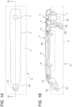
- FIG. 1A and FIG. 1B show a handle device to which the present disclosure is applied.
- a handle device (A) includes a vehicle handle of the present disclosure and a handle base 11 for fixing the vehicle handle to a door, and the vehicle handle can be rotated around a rotation center (CH) in a state of being attached to the handle base 11.
- CH rotation center
- the door latch device can perform a transition operation between a locked state and an unlocked state by an electronic control device (not shown).
- the unlocked state when the latch release operation force is applied, the latch holding a closed state of the door is released and a door opening operation is enabled.
- the latch release operation force is applied, that is, even when the rotating operation is applied to the vehicle handle in the locked state, the latch is not released, and a closed state of the door is maintained.
- the cylinder lock 1 is fixed to the handle base 11 as an auxiliary locking and unlocking operation means for the door latch device by the electronic control device, and even when the door latch device is in the locked state, the door latch device can be shifted to the unlocked state by the unlocking operation of the cylinder lock 1 by the user performing the latch release operation.
- the vehicle handle includes a handle body portion 3 having an operation opening 2 for allowing access to the cylinder lock 1, and a cap 4 for normally closing the operation opening 2 of the handle body portion 3.
- the handle body portion 3 is formed by connecting a cover handle 13 that constitutes an outer appearance of the vehicle handle to a base handle 12 on which the operation leg portion 12a or the like are formed by bolts 14 or the like.
- a handle recess 12d serving as a handle for operating the vehicle handle is formed in a central portion of the base handle 12, and a front end portion (in this specification, a left side in FIG. 1 is referred to as “front”, a right side is referred to as “rear”, an upper side in FIG. 1B is referred to as a “front side”, and an opposite side is referred to as a “back side”) is provided with a hinge protruding portion 12e for providing a rotation center (CH) of the vehicle handle.
- a left side in FIG. 1 is referred to as "front”
- a right side is referred to as "rear”
- an upper side in FIG. 1B is referred to as a "front side”
- an opposite side is referred to as a “back side”
- CH rotation center
- the cover handle 13 is formed in a tray shape in which a peripheral edge is raised to the back side, and an operation opening 2 is formed in a rear end portion.
- FIG. 2A and FIG. 2B are views showing a cover handle, wherein FIG. 2A is a front view, and FIG. 2B is a cross-sectional view taken along a line 2B-2B in FIG. 2A .
- FIG. 3A and FIG. 3B are views showing an elastic locking portion, wherein FIG. 3A is a view showing attachment operation to the cover handle, and FIG. 3B is a view showing a state in which the elastic locking portion is fixed to the cover handle.
- the operation opening 2 includes a fitting recess 2a into which a design forming portion 4a of the cap 4 to be described later is fitted, and a through hole portion 2c that penetrates a bulging portion 2b protruding from a center portion of the fitting recess 2a in a back surface direction.
- a planar cap locking surface 2d continuing to the through hole portion 2c is formed on a back-side end surface of a rear end portion of the bulging portion 2b.
- the through hole portion 2c is formed as a circular hole, and the bulging portion 2b is formed in a cylindrical shape.
- a pushing recess 2e having a sloping surface whose height gradually decreases from the rear to the front is formed on a bottom surface of the bulging portion 2b.
- the pushing recess 2e provides an escape of a finger when the attached cap 4 is removed.
- spring locking portions 9 and a spring retainer 13a protrude from the back surface of the cover handle 13, and slits 13b each having a height dimension slightly larger than a wire diameter of a spring 6 to be described later are formed at opposing positions in the spring retainer 13a and the bulging portion 2b.
- an elastic locking portion 6 is formed in the vicinity of the operation opening 2.
- the elastic locking portion is a spring formed by bending a spring wire having a circular cross section, and includes a main body portion 7 bent in a substantially circular shape, and locking bent portions 8 that can be locked to the spring locking portions 9 by folding back both free ends of the main body portion 7.
- positions and the like of the spring 6 and the spring locking portions 9 are set such that a part of the main body portion 7 protrudes into the through hole portion 2c from the slit 13b formed in the bulging portion 2b in a state in which the locking bent portions 8 are locked to the spring locking portions 9, and a part facing an entrance to the operation opening 2 enters the slit 13b of the spring retainer 13a.
- FIG. 4A to FIG. 4E are views showing a cap, wherein FIG. 4A is a front view, FIG. 4B is a view taken in a direction of an arrow 4B of FIG. 4A, FIG. 4C is a cross-sectional view taken along a line 4C-4C of FIG. 4A, FIG. 4D is a view taken in a direction of an arrow 4D of FIG. 4B, and FIG. 4E is a perspective view seen from a back surface direction.
- FIG. 5A to FIG. 5E are views showing attaching operation of the cap, wherein FIG. 5A is a view showing an unattached state, FIG. 5B is a view showing a start of the attaching operation, FIG.
- FIG. 5C is a view showing a state in which the cap is rotated
- FIG. 5D is a view showing a state in which the attachment is completed
- FIG. 5E is an enlarged view of a main portion of FIG. 5D
- FIG. 6 is a diagram showing a method of removing the cap.
- the cap 4 that closes the operation opening 2 to prevent the exposure of the cylinder lock 1 to the outside has a design forming portion 4a that has a shape similar to a front view shape of the fitting recess 2a of the operation opening 2 and can be fitted into the fitting recess 2a, and a fitting protruding portion 4b protrudes from a back surface of the design forming portion 4a.
- the fitting protruding portion 4b can be fitted into the through hole portion 2c of the operation opening 2 in an oblique posture.
- a locked portion 5 is formed on a back side with respect to a cut 4c by forming the cut 4c facing the slit 13b of a bulging portion 2b in a state in which the cap 4 is attached to the operation opening 2.
- a front-side wall surface of the locked portion 5 is formed with a locking surface 10 which is a sloping surface gradually inclined toward the front surface toward a center portion of the fitting protruding portion 4b, and the back-side end surface of the fitting protruding portion 4b is formed with an attaching sloping surface 4d at a position overlapping the locking surface 10 in a plan view.
- the attaching sloping surface 4d is a sloping surface that is gradually inclined toward the back surface toward the central portion of the fitting protruding portion 4b, that is, a sloping surface that is gradually inclined forward and upward toward a free end, while the locking surface 10 is formed as a sloping surface that is inclined forward and downward toward the free end.
- a locking step portion 4e to be locked to the cap locking surface 2d in a state in which the cap 4 is attached to the operation opening 2 protrudes from a rear-end side wall portion of the fitting protruding portion 4b.
- the spring 6 is held in a posture substantially parallel to a back surface of the cover handle 13 in a state in which the spring 6 is attached to the cover handle 13, and when two opposing positions of the main body portion 7 are inserted into the slits 13b of the bulging portion 2b and the spring retainer 13a, the spring 6 is prevented from coming off from the cover handle 13.
- the spring 6 When a force in a pushing direction is further applied to the cap 4 from this state, the spring 6 is pushed toward the center by the attaching sloping surface 4d of the cap 4 and elastically deformed in a direction in which the main body portion 7 is reduced in diameter to allow passage of the locked portion 5. Thereafter, the cap 4 elastically returns to an original position and is elastically locked to the locked portion 5 of the cap 4 as shown in FIG. 5D .
- the locking step portion 4e of the cap 4 is locked to the cap locking surface 2d of the cover handle 13, and the spring 6 restricts the movement of the locked portion 5 toward the front side, thereby separation of the cap 4 from the operation opening 2 is restricted.
- the spring 6 is slightly bent and, as shown in FIG. 5E , is pressed-contact against the locking surface 10 of the cap 4 by an elastic restoring force.
- a component force toward the back side acts on the locking surface 10 of the cap 4, and a back surface of a peripheral edge portion of the design forming portion 4a of the cap 4 is pressed against a front surface wall of the fitting recess 2a to prevent rattling.
- the cap 4 When the cap 4 is removed from this state, as shown in FIG. 6 , the entire vehicle handle is once rotated around the rotation center (CH).
- the latch release operation of a door latch is not performed by this operation, and in this state, the cap 4 can be removed using a space that is formed between the cylinder lock 1 and the cap 4 and is large enough for a finger to fit through.
- the cap 4 can be removed by pushing up the back-side end surface of the fitting protruding portion 4b of the cap 4 to the front side with a finger as indicated by arrows in FIG. 5E .
- a counterclockwise rotational force in FIG. 5E is generated in the cap 4 with a contact portion between the locking step portion 4e and the cap locking surface 2d of the cover handle 13 as a fulcrum, and the locking surface 10 applies a pushing force to the spring 6 toward the center.
- the spring 6 retreats in an unlocking direction with respect to the locked portion 5 to allow the cap 4 to rotate, and the pushing recess 2e formed in the fitting protruding portion 4b provides an operation space for the cap 4, so that the cap 4 can be separated from the operation opening 2.
Landscapes
- Engineering & Computer Science (AREA)
- Mechanical Engineering (AREA)
- Lock And Its Accessories (AREA)
Abstract
Provided is a vehicle handle installed on a door of a vehicle such that a pulling operation can be carried out on the vehicle handle, the vehicle handle comprising a handle body portion which is provided with an opening for operation to a cylinder lock installed in the door and a cap which closes the opening for operation. An elastic lock portion is provided to one of the cap and the handle body and a locked portion is provided to the other one thereof. The elastic lock portion is translated along a door surface as a result of an attaching/detaching operation of the cap to/from the opening for operation, and is elastically locked to and unlocked from the locked portion.
Description
- The present disclosure relates to a vehicle handle.
- As a vehicle handle used to open and close a door of a vehicle, a vehicle handle described in
Patent Literature 1 is known. - As shown in
FIG. 7A and FIG. 7B , the handle in an example of the related art includes a handle body portion 3' having a key access opening 2' communicating with a key operation portion of a cylinder lock used for unlocking operation in an emergency or the like. - The key access opening 2' of the handle body portion 3' is closed by a cap 4' in an attachable and detachable manner in order to prevent the cylinder lock from being exposed to the outside in a normal state, and the cap 4' is removed when access to the cylinder lock is required.
- The cap 4' includes a
cylindrical portion 4b' protruding from a capmain body portion 4a' in a back surface direction, and a part of thecylindrical portion 4b' is separated via aslit 4c' to form alocking leg 4d' that is elastically deformable. When alocking protrusion 4e' is inflated at a tip end of thelocking leg 4d' and thecap 4 is pushed into the key access opening 2', thelocking protrusion 4e' interferes with a peripheral wall of a fittingcylindrical portion 3a' that protrudes from the key access opening 2' to a back side, and after thelocking leg 4d' is once elastically deformed and returns to an original position, thelocking protrusion 4e' is elastically locked to the fittingcylindrical portion 3a', and attaching operation of thecap 4 is completed. - When a tip end of the
cylindrical portion 4b' of thecap 4 is pushed out to a front side from an attached state, thelocking leg 4d' is once elastically deformed, the locking of thelocking protrusion 4e' is released, and the cap 4' can be removed. - However, in the above-described example in the related art, since the attachment and detachment of the cap 4' is accompanied by the elastic deformation of the
locking leg 4d', it is necessary to ensure an arm length of thelocking leg 4d' to prevent reduction of operability due to an excessive operation force during the attachment and detachment operation of thecap 4, in particular, the detachment operation. - However, if the arm length is increased, a length from the cap
main body portion 4a' to the tip end of the cylindrical portion is increased, and as a result, a distance between a cylinder lock (not shown) disposed on a deep side thereof and a front surface of the handle body portion 3' is also increased, resulting in a problem of reduced operability of the cylinder lock. - Patent Literature 1:
EP2,853,664B1 - The present disclosure provides a vehicle handle in which a cylinder lock is capable of being disposed near a front surface of a handle body portion.
- According to the present disclosure, a vehicle handle to be attached to a door of a vehicle such that the vehicle handle is operable to be pulled out, the vehicle handle includes:
- a
handle body portion 3 having an operation opening 2 for acylinder lock 1 attached to the door; and - a
cap 4 configured to close theoperation opening 2, in which - an
elastic locking portion 6 is provided on one of thecap 4 and thehandle body portion 3, theelastic locking portion 6 being translationally moved along a door front surface in accordance with an attachment and detachment of thecap 4 with respect to theoperation opening 2, and being elastically locked to and unlocked from a lockedportion 5 provided on the other of the cap and the handle body portion. - The vehicle handle includes: the
handle body portion 3 in which the operation opening 2 to thecylinder lock 1 is opened; and thecap 4 that can be attached to and detached from theoperation opening 2 and closes the operation opening 2 in an attached state to prevent thecylinder lock 1 from being exposed to the outside. The lockedportion 5 is formed on one of thecap 4 and thehandle body portion 3, and theelastic locking portion 6 is formed on the other of the cap and the handle body portion, theelastic locking portion 6 being translationally moved along a door front surface on which thecylinder lock 1 is disposed in accordance with the attachment and detachment of thecap 4 with respect to theoperation opening 2, and being elastically locked to and unlocked from the lockedportion 5. - In the present disclosure in which the
elastic locking portion 6 is translationally moved along the front surface of the door at the time of being locked to and unlocked from the lockedportion 5, it is not necessary to set a movement space or the like for theelastic locking portion 6 in a height direction of thehandle body portion 3. Thus, thecylinder lock 1 can be disposed near the front surface of thehandle body portion 3, and operability of thecylinder lock 1 can be improved. - Further, the
elastic locking portion 6 can be configured as a spring having both ends held by thehandle body portion 3 and an intermediate portion moving forward and backward with respect to a path for the attachment and detachment of thecap 4. In this case, theelastic locking portion 6 can be formed of an elastic material, and can be held by engaginglocking bent portions 8 formed at both ends of an arc-shapedmain body portion 7 tospring locking portions 9 formed in thehandle body portion 3. - Further, the locked
portion 5 is formed in thecap 4, and alocking surface 10 of the lockedportion 5 can be formed by a sloping surface which is inclined forward and downward toward a free end portion, and
when theelastic locking portion 6 is pressed-contact with thelocking surface 10 in a state of being engaged to the lockedportion 5, a component force in an attaching direction acts on thecap 4 due to the elasticity of theelastic locking portion 6, and thus rattling in the attaching state can be prevented. - According to the present disclosure, the cylinder lock can be disposed near the front surface of the handle body portion, and the operability for the cylinder lock can be enhanced.
-
-
FIG. 1A and FIG. 1B are views showing a handle device to which the present disclosure is applied, whereinFIG. 1A is a front view andFIG. 1B is a cross-sectional view taken along aline 1B-1B inFIG. 1A . -
FIG. 2A and FIG. 2B are views showing a cover handle, whereinFIG. 2A is a front view, andFIG. 2B is a cross-sectional view taken along aline 2B-2B inFIG. 2A . -
FIG. 3A and FIG. 3B are views showing an elastic locking portion, whereinFIG. 3A is a view showing attachment operation to the cover handle, andFIG. 3B is a view showing a state in which the elastic locking portion is fixed to the cover handle. -
FIG. 4A to FIG. 4E are views showing a cap, whereinFIG. 4A is a front view,FIG. 4B is a view taken in a direction of anarrow 4B ofFIG. 4A, FIG. 4C is a cross-sectional view taken along aline 4C-4C ofFIG. 4A, FIG. 4D is a view taken in a direction of anarrow 4D ofFIG. 4B, and FIG. 4E is a perspective view seen from a back surface direction. -
FIG. 5A to FIG. 5E are views showing attaching operation of the cap, whereinFIG. 5A is a view showing an unattached state,FIG. 5B is a view showing a start of the attaching operation,FIG. 5C is a view showing a state in which the cap is rotated,FIG. 5D is a view showing a state in which the attachment is completed, andFIG. 5E is an enlarged view of a main portionFIG. 5D . -
FIG. 6 is a diagram showing a method of removing the cap. -
FIG. 7A and FIG. 7B are views showing an example in the conventional art, whereinFIG. 7A is a perspective view shown inFIG. 2 ofPatent Literature 1, andFIG. 7B is a cross-sectional view shown inFIG. 6 ofPatent Literature 1. -
FIG. 1A and FIG. 1B show a handle device to which the present disclosure is applied. - A handle device (A) includes a vehicle handle of the present disclosure and a
handle base 11 for fixing the vehicle handle to a door, and the vehicle handle can be rotated around a rotation center (CH) in a state of being attached to thehandle base 11. - When the vehicle handle is rotated around the rotation center (CH) such that a rotation tip end side is pulled out from a door surface, an
operation leg portion 12a moves in a door front surface direction, alever 12b connected to thehandle base 11 rotates around arotation shaft 12c, and is transmitted as a latch release operation force to a door latch device (not shown). - The door latch device can perform a transition operation between a locked state and an unlocked state by an electronic control device (not shown). In the unlocked state, when the latch release operation force is applied, the latch holding a closed state of the door is released and a door opening operation is enabled. On the other hand, even when the latch release operation force is applied, that is, even when the rotating operation is applied to the vehicle handle in the locked state, the latch is not released, and a closed state of the door is maintained.
- Further, the
cylinder lock 1 is fixed to thehandle base 11 as an auxiliary locking and unlocking operation means for the door latch device by the electronic control device, and even when the door latch device is in the locked state, the door latch device can be shifted to the unlocked state by the unlocking operation of thecylinder lock 1 by the user performing the latch release operation. - The vehicle handle includes a
handle body portion 3 having anoperation opening 2 for allowing access to thecylinder lock 1, and acap 4 for normally closing the operation opening 2 of thehandle body portion 3. In this example, thehandle body portion 3 is formed by connecting acover handle 13 that constitutes an outer appearance of the vehicle handle to abase handle 12 on which theoperation leg portion 12a or the like are formed bybolts 14 or the like. - A
handle recess 12d serving as a handle for operating the vehicle handle is formed in a central portion of thebase handle 12, and a front end portion (in this specification, a left side inFIG. 1 is referred to as "front", a right side is referred to as "rear", an upper side inFIG. 1B is referred to as a "front side", and an opposite side is referred to as a "back side") is provided with ahinge protruding portion 12e for providing a rotation center (CH) of the vehicle handle. - The cover handle 13 is formed in a tray shape in which a peripheral edge is raised to the back side, and an
operation opening 2 is formed in a rear end portion. -
FIG. 2A and FIG. 2B are views showing a cover handle, whereinFIG. 2A is a front view, andFIG. 2B is a cross-sectional view taken along aline 2B-2B inFIG. 2A .FIG. 3A and FIG. 3B are views showing an elastic locking portion, whereinFIG. 3A is a view showing attachment operation to the cover handle, andFIG. 3B is a view showing a state in which the elastic locking portion is fixed to the cover handle. - As shown in
FIG. 2A to FIG. 3B , theoperation opening 2 includes afitting recess 2a into which adesign forming portion 4a of thecap 4 to be described later is fitted, and a throughhole portion 2c that penetrates a bulgingportion 2b protruding from a center portion of thefitting recess 2a in a back surface direction. A planarcap locking surface 2d continuing to the throughhole portion 2c is formed on a back-side end surface of a rear end portion of the bulgingportion 2b. - In this example, the through
hole portion 2c is formed as a circular hole, and the bulgingportion 2b is formed in a cylindrical shape. - As shown in
FIG. 2B , a pushingrecess 2e having a sloping surface whose height gradually decreases from the rear to the front is formed on a bottom surface of the bulgingportion 2b. As will be described later, the pushingrecess 2e provides an escape of a finger when the attachedcap 4 is removed. - As shown in
FIG. 2A to FIG. 3B ,spring locking portions 9 and aspring retainer 13a protrude from the back surface of thecover handle 13, and slits 13b each having a height dimension slightly larger than a wire diameter of aspring 6 to be described later are formed at opposing positions in thespring retainer 13a and the bulgingportion 2b. - Further, an
elastic locking portion 6 is formed in the vicinity of theoperation opening 2. In this example, the elastic locking portion is a spring formed by bending a spring wire having a circular cross section, and includes amain body portion 7 bent in a substantially circular shape, and lockingbent portions 8 that can be locked to thespring locking portions 9 by folding back both free ends of themain body portion 7. - As shown in
FIG. 3B , positions and the like of thespring 6 and thespring locking portions 9 are set such that a part of themain body portion 7 protrudes into the throughhole portion 2c from theslit 13b formed in the bulgingportion 2b in a state in which the lockingbent portions 8 are locked to thespring locking portions 9, and a part facing an entrance to theoperation opening 2 enters theslit 13b of thespring retainer 13a. -
FIG. 4A to FIG. 4E are views showing a cap, whereinFIG. 4A is a front view,FIG. 4B is a view taken in a direction of anarrow 4B ofFIG. 4A, FIG. 4C is a cross-sectional view taken along aline 4C-4C ofFIG. 4A, FIG. 4D is a view taken in a direction of anarrow 4D ofFIG. 4B, and FIG. 4E is a perspective view seen from a back surface direction.FIG. 5A to FIG. 5E are views showing attaching operation of the cap, whereinFIG. 5A is a view showing an unattached state,FIG. 5B is a view showing a start of the attaching operation,FIG. 5C is a view showing a state in which the cap is rotated,FIG. 5D is a view showing a state in which the attachment is completed, andFIG. 5E is an enlarged view of a main portion ofFIG. 5D .FIG. 6 is a diagram showing a method of removing the cap. - As shown in
FIG. 4A to FIG. 4E , thecap 4 that closes theoperation opening 2 to prevent the exposure of thecylinder lock 1 to the outside has adesign forming portion 4a that has a shape similar to a front view shape of thefitting recess 2a of theoperation opening 2 and can be fitted into thefitting recess 2a, and a fitting protrudingportion 4b protrudes from a back surface of thedesign forming portion 4a. As shown inFIG. 5C , thefitting protruding portion 4b can be fitted into the throughhole portion 2c of theoperation opening 2 in an oblique posture. On a side wall portion thereof, a lockedportion 5 is formed on a back side with respect to acut 4c by forming thecut 4c facing theslit 13b of a bulgingportion 2b in a state in which thecap 4 is attached to theoperation opening 2. - A front-side wall surface of the locked
portion 5 is formed with a lockingsurface 10 which is a sloping surface gradually inclined toward the front surface toward a center portion of the fitting protrudingportion 4b, and the back-side end surface of the fitting protrudingportion 4b is formed with an attachingsloping surface 4d at a position overlapping the lockingsurface 10 in a plan view. The attachingsloping surface 4d is a sloping surface that is gradually inclined toward the back surface toward the central portion of the fitting protrudingportion 4b, that is, a sloping surface that is gradually inclined forward and upward toward a free end, while the lockingsurface 10 is formed as a sloping surface that is inclined forward and downward toward the free end. - Further, a locking
step portion 4e to be locked to thecap locking surface 2d in a state in which thecap 4 is attached to theoperation opening 2 protrudes from a rear-end side wall portion of the fitting protrudingportion 4b. - According to this example, as shown in
FIG. 5A , thespring 6 is held in a posture substantially parallel to a back surface of the cover handle 13 in a state in which thespring 6 is attached to thecover handle 13, and when two opposing positions of themain body portion 7 are inserted into theslits 13b of the bulgingportion 2b and thespring retainer 13a, thespring 6 is prevented from coming off from thecover handle 13. - From this state, as shown in
FIG. 5B , when a back surface of a rear end portion of thedesign forming portion 4a of thecap 4 is placed on a bottom wall of thefitting recess 2a, and then a front end portion of thedesign forming portion 4a is rotated counterclockwise inFIG. 5B so as to be pressed with the abutting portion as a fulcrum, as shown inFIG. 5C , the attaching slopingsurface 4d comes into contact with a portion of thespring 6 protruding into the throughhole portion 2c. When a force in a pushing direction is further applied to thecap 4 from this state, thespring 6 is pushed toward the center by the attaching slopingsurface 4d of thecap 4 and elastically deformed in a direction in which themain body portion 7 is reduced in diameter to allow passage of the lockedportion 5. Thereafter, thecap 4 elastically returns to an original position and is elastically locked to the lockedportion 5 of thecap 4 as shown inFIG. 5D . - In the locked state, the locking
step portion 4e of thecap 4 is locked to thecap locking surface 2d of thecover handle 13, and thespring 6 restricts the movement of the lockedportion 5 toward the front side, thereby separation of thecap 4 from theoperation opening 2 is restricted. - Further, in the attached state of the
cap 4, thespring 6 is slightly bent and, as shown inFIG. 5E , is pressed-contact against the lockingsurface 10 of thecap 4 by an elastic restoring force. As a result, a component force toward the back side acts on the lockingsurface 10 of thecap 4, and a back surface of a peripheral edge portion of thedesign forming portion 4a of thecap 4 is pressed against a front surface wall of thefitting recess 2a to prevent rattling. - When the
cap 4 is removed from this state, as shown inFIG. 6 , the entire vehicle handle is once rotated around the rotation center (CH). When the door latch device is not in the unlocked state, the latch release operation of a door latch is not performed by this operation, and in this state, thecap 4 can be removed using a space that is formed between thecylinder lock 1 and thecap 4 and is large enough for a finger to fit through. - The
cap 4 can be removed by pushing up the back-side end surface of the fitting protrudingportion 4b of thecap 4 to the front side with a finger as indicated by arrows inFIG. 5E . When thecap 4 is pushed up, a counterclockwise rotational force inFIG. 5E is generated in thecap 4 with a contact portion between the lockingstep portion 4e and thecap locking surface 2d of the cover handle 13 as a fulcrum, and the lockingsurface 10 applies a pushing force to thespring 6 toward the center. - As a result, the
spring 6 retreats in an unlocking direction with respect to the lockedportion 5 to allow thecap 4 to rotate, and the pushingrecess 2e formed in thefitting protruding portion 4b provides an operation space for thecap 4, so that thecap 4 can be separated from theoperation opening 2. - Although various embodiments have been described above with reference to the drawings, it is needless to say that the present disclosure is not limited to such embodiments. It is apparent to those skilled in the art that various variations or modifications can be conceived within the scope described in the claims, and it is understood that the variations or modifications naturally fall within the technical scope of the present disclosure. Further, the components described in the above embodiments may be freely combined without departing from the spirit of the disclosure.
- The present application is based on Japanese Patent Application (
Japanese Patent Application No. 2022-074269) filed on April 28, 2022 -
- 1 cylinder lock
- 2 operation opening
- 3 handle body portion
- 4 cap
- 5 locked portion
- 6 elastic locking portion
- 7 main body portion
- 8 locking bent portion
- 9 spring locking portion
- 10 locking surface
Claims (4)
- A vehicle handle to be attached to a door of a vehicle such that the vehicle handle is operable to be pulled out, the vehicle handle comprising:a handle body portion having an operation opening for a cylinder lock to be attached to the door; anda cap configured to close the operation opening, whereinan elastic locking portion is provided on one of the cap and the handle body portion, the elastic locking portion being translationally moved along a door front surface in accordance with an attachment and detachment of the cap with respect to the operation opening, and being elastically locked to and unlocked from a locked portion provided on the other of the cap and the handle body portion.
- The vehicle handle according to claim 1, wherein
the elastic locking portion is a spring having both ends held by the handle body portion and an intermediate portion moving forward and backward with respect to a path for the attachment and detachment of the cap. - The vehicle handle according to claim 2, wherein
the elastic locking portion is formed of an elastic material, and is held by engaging locking bent portions formed at both ends of an arc-shaped main body portion to a spring locking portion formed in the handle body portion. - The vehicle handle according to claim 1, whereinthe locked portion is formed in the cap, and a locking surface of the locked portion is formed by a sloping surface inclined forward and downward toward a free end portion, andthe elastic locking portion is pressed-contact with the locking surface in a state of being engaged to the locked portion.
Applications Claiming Priority (2)
| Application Number | Priority Date | Filing Date | Title |
|---|---|---|---|
| JP2022074269A JP7778638B2 (en) | 2022-04-28 | 2022-04-28 | Vehicle handle |
| PCT/JP2023/016026 WO2023210551A1 (en) | 2022-04-28 | 2023-04-21 | Vehicle handle |
Publications (1)
| Publication Number | Publication Date |
|---|---|
| EP4517033A1 true EP4517033A1 (en) | 2025-03-05 |
Family
ID=88518836
Family Applications (1)
| Application Number | Title | Priority Date | Filing Date |
|---|---|---|---|
| EP23796291.5A Pending EP4517033A1 (en) | 2022-04-28 | 2023-04-21 | Vehicle handle |
Country Status (5)
| Country | Link |
|---|---|
| US (1) | US20250043598A1 (en) |
| EP (1) | EP4517033A1 (en) |
| JP (1) | JP7778638B2 (en) |
| CN (1) | CN119096023A (en) |
| WO (1) | WO2023210551A1 (en) |
Families Citing this family (1)
| Publication number | Priority date | Publication date | Assignee | Title |
|---|---|---|---|---|
| WO2025215823A1 (en) * | 2024-04-12 | 2025-10-16 | 日産自動車株式会社 | Door handle device |
Family Cites Families (5)
| Publication number | Priority date | Publication date | Assignee | Title |
|---|---|---|---|---|
| JP2002295059A (en) * | 2001-03-29 | 2002-10-09 | Honda Lock Mfg Co Ltd | Out handle device of vehicle |
| KR20140077869A (en) * | 2011-02-01 | 2014-06-24 | 아닥 플라스틱스 인코포레이티드 | Vehicle door handle assembly with concealed key cylinder |
| DE102013016070A1 (en) * | 2013-09-27 | 2015-04-02 | Huf Hülsbeck & Fürst Gmbh & Co. Kg | door handle |
| JP6612686B2 (en) * | 2016-06-21 | 2019-11-27 | 株式会社ホンダロック | Outdoor handle device for vehicle door |
| JP7648367B2 (en) | 2020-11-04 | 2025-03-18 | 株式会社三共 | Gaming Machines |
-
2022
- 2022-04-28 JP JP2022074269A patent/JP7778638B2/en active Active
-
2023
- 2023-04-21 EP EP23796291.5A patent/EP4517033A1/en active Pending
- 2023-04-21 WO PCT/JP2023/016026 patent/WO2023210551A1/en not_active Ceased
- 2023-04-21 CN CN202380036400.5A patent/CN119096023A/en active Pending
-
2024
- 2024-10-25 US US18/927,241 patent/US20250043598A1/en active Pending
Also Published As
| Publication number | Publication date |
|---|---|
| CN119096023A (en) | 2024-12-06 |
| JP2023163385A (en) | 2023-11-10 |
| WO2023210551A1 (en) | 2023-11-02 |
| JP7778638B2 (en) | 2025-12-02 |
| US20250043598A1 (en) | 2025-02-06 |
Similar Documents
| Publication | Publication Date | Title |
|---|---|---|
| US5411302A (en) | Powered closing device | |
| CN101426662B (en) | Pushing-up device | |
| EP2053186A1 (en) | Device for preventing unlocking of door handle | |
| US10267067B2 (en) | Apparatus for preventing vehicle door having outside handle from opening | |
| JPS6055672B2 (en) | Automobile door lock device | |
| KR101806622B1 (en) | Assembly of hood latch for vehicle and operation method thereof | |
| US20250043598A1 (en) | Vehicle handle | |
| EP3748110A1 (en) | Inside handle device | |
| JPH09254659A (en) | Car door handle | |
| JP4543453B2 (en) | Lid opening / closing device | |
| US12203301B2 (en) | Lock lever and opening/closing device | |
| US20250270859A1 (en) | Vehicle door handle device | |
| CN217380131U (en) | Door outside handle assembly and vehicle | |
| US20220307299A1 (en) | Vehicle lock device | |
| CN102144070B (en) | Door handle device | |
| JPH0122764Y2 (en) | ||
| KR100579641B1 (en) | Center Passer Tray Lock | |
| JP3348048B2 (en) | Closed lock handle device for sliding door | |
| EP4617455A1 (en) | Door handle device | |
| JP2747265B2 (en) | Lock release structure of electronic device with protective lid | |
| JP3325242B2 (en) | Locking device with lock | |
| JP7272297B2 (en) | Vehicle door opening device | |
| JP3304332B2 (en) | Locking device with lock | |
| KR200228009Y1 (en) | Console of automobile | |
| JP3184452B2 (en) | Open / close lid structure for shift lock release button operation |
Legal Events
| Date | Code | Title | Description |
|---|---|---|---|
| STAA | Information on the status of an ep patent application or granted ep patent |
Free format text: STATUS: THE INTERNATIONAL PUBLICATION HAS BEEN MADE |
|
| PUAI | Public reference made under article 153(3) epc to a published international application that has entered the european phase |
Free format text: ORIGINAL CODE: 0009012 |
|
| STAA | Information on the status of an ep patent application or granted ep patent |
Free format text: STATUS: REQUEST FOR EXAMINATION WAS MADE |
|
| 17P | Request for examination filed |
Effective date: 20241118 |
|
| AK | Designated contracting states |
Kind code of ref document: A1 Designated state(s): AL AT BE BG CH CY CZ DE DK EE ES FI FR GB GR HR HU IE IS IT LI LT LU LV MC ME MK MT NL NO PL PT RO RS SE SI SK SM TR |
|
| DAV | Request for validation of the european patent (deleted) | ||
| DAX | Request for extension of the european patent (deleted) |