EP4517014A1 - Flush toilet - Google Patents
Flush toilet Download PDFInfo
- Publication number
- EP4517014A1 EP4517014A1 EP24192972.8A EP24192972A EP4517014A1 EP 4517014 A1 EP4517014 A1 EP 4517014A1 EP 24192972 A EP24192972 A EP 24192972A EP 4517014 A1 EP4517014 A1 EP 4517014A1
- Authority
- EP
- European Patent Office
- Prior art keywords
- water
- flush
- overflow
- toilet
- main body
- Prior art date
- Legal status (The legal status is an assumption and is not a legal conclusion. Google has not performed a legal analysis and makes no representation as to the accuracy of the status listed.)
- Pending
Links
Images




Classifications
-
- E—FIXED CONSTRUCTIONS
- E03—WATER SUPPLY; SEWERAGE
- E03D—WATER-CLOSETS OR URINALS WITH FLUSHING DEVICES; FLUSHING VALVES THEREFOR
- E03D11/00—Other component parts of water-closets, e.g. noise-reducing means in the flushing system, flushing pipes mounted in the bowl, seals for the bowl outlet, devices preventing overflow of the bowl contents; devices forming a water seal in the bowl after flushing, devices eliminating obstructions in the bowl outlet or preventing backflow of water and excrements from the waterpipe
- E03D11/02—Water-closet bowls ; Bowls with a double odour seal optionally with provisions for a good siphonic action; siphons as part of the bowl
-
- E—FIXED CONSTRUCTIONS
- E03—WATER SUPPLY; SEWERAGE
- E03C—DOMESTIC PLUMBING INSTALLATIONS FOR FRESH WATER OR WASTE WATER; SINKS
- E03C1/00—Domestic plumbing installations for fresh water or waste water; Sinks
- E03C1/02—Plumbing installations for fresh water
- E03C1/10—Devices for preventing contamination of drinking-water pipes, e.g. means for aerating self-closing flushing valves
- E03C1/102—Devices for preventing contamination of drinking-water pipes, e.g. means for aerating self-closing flushing valves using an air gap device
-
- E—FIXED CONSTRUCTIONS
- E03—WATER SUPPLY; SEWERAGE
- E03C—DOMESTIC PLUMBING INSTALLATIONS FOR FRESH WATER OR WASTE WATER; SINKS
- E03C1/00—Domestic plumbing installations for fresh water or waste water; Sinks
- E03C1/02—Plumbing installations for fresh water
- E03C1/10—Devices for preventing contamination of drinking-water pipes, e.g. means for aerating self-closing flushing valves
- E03C1/104—Devices for preventing contamination of drinking-water pipes, e.g. means for aerating self-closing flushing valves using a single check valve
-
- E—FIXED CONSTRUCTIONS
- E03—WATER SUPPLY; SEWERAGE
- E03D—WATER-CLOSETS OR URINALS WITH FLUSHING DEVICES; FLUSHING VALVES THEREFOR
- E03D1/00—Water flushing devices with cisterns ; Setting up a range of flushing devices or water-closets; Combinations of several flushing devices
-
- E—FIXED CONSTRUCTIONS
- E03—WATER SUPPLY; SEWERAGE
- E03D—WATER-CLOSETS OR URINALS WITH FLUSHING DEVICES; FLUSHING VALVES THEREFOR
- E03D1/00—Water flushing devices with cisterns ; Setting up a range of flushing devices or water-closets; Combinations of several flushing devices
- E03D1/24—Low-level flushing systems
- E03D1/26—Bowl with flushing cistern mounted on the rearwardly extending end of the bowl
-
- E—FIXED CONSTRUCTIONS
- E03—WATER SUPPLY; SEWERAGE
- E03D—WATER-CLOSETS OR URINALS WITH FLUSHING DEVICES; FLUSHING VALVES THEREFOR
- E03D1/00—Water flushing devices with cisterns ; Setting up a range of flushing devices or water-closets; Combinations of several flushing devices
- E03D1/30—Valves for high or low level cisterns; Their arrangement ; Flushing mechanisms in the cistern, optionally with provisions for a pre-or a post- flushing and for cutting off the flushing mechanism in case of leakage
-
- E—FIXED CONSTRUCTIONS
- E03—WATER SUPPLY; SEWERAGE
- E03D—WATER-CLOSETS OR URINALS WITH FLUSHING DEVICES; FLUSHING VALVES THEREFOR
- E03D1/00—Water flushing devices with cisterns ; Setting up a range of flushing devices or water-closets; Combinations of several flushing devices
- E03D1/30—Valves for high or low level cisterns; Their arrangement ; Flushing mechanisms in the cistern, optionally with provisions for a pre-or a post- flushing and for cutting off the flushing mechanism in case of leakage
- E03D1/32—Arrangement of inlet valves
-
- E—FIXED CONSTRUCTIONS
- E03—WATER SUPPLY; SEWERAGE
- E03D—WATER-CLOSETS OR URINALS WITH FLUSHING DEVICES; FLUSHING VALVES THEREFOR
- E03D1/00—Water flushing devices with cisterns ; Setting up a range of flushing devices or water-closets; Combinations of several flushing devices
- E03D1/30—Valves for high or low level cisterns; Their arrangement ; Flushing mechanisms in the cistern, optionally with provisions for a pre-or a post- flushing and for cutting off the flushing mechanism in case of leakage
- E03D1/33—Adaptations or arrangements of floats
-
- E—FIXED CONSTRUCTIONS
- E03—WATER SUPPLY; SEWERAGE
- E03D—WATER-CLOSETS OR URINALS WITH FLUSHING DEVICES; FLUSHING VALVES THEREFOR
- E03D1/00—Water flushing devices with cisterns ; Setting up a range of flushing devices or water-closets; Combinations of several flushing devices
- E03D1/30—Valves for high or low level cisterns; Their arrangement ; Flushing mechanisms in the cistern, optionally with provisions for a pre-or a post- flushing and for cutting off the flushing mechanism in case of leakage
- E03D1/34—Flushing valves for outlets; Arrangement of outlet valves
-
- E—FIXED CONSTRUCTIONS
- E03—WATER SUPPLY; SEWERAGE
- E03D—WATER-CLOSETS OR URINALS WITH FLUSHING DEVICES; FLUSHING VALVES THEREFOR
- E03D1/00—Water flushing devices with cisterns ; Setting up a range of flushing devices or water-closets; Combinations of several flushing devices
- E03D1/38—Adaptations or arrangements of flushing pipes
-
- E—FIXED CONSTRUCTIONS
- E03—WATER SUPPLY; SEWERAGE
- E03D—WATER-CLOSETS OR URINALS WITH FLUSHING DEVICES; FLUSHING VALVES THEREFOR
- E03D11/00—Other component parts of water-closets, e.g. noise-reducing means in the flushing system, flushing pipes mounted in the bowl, seals for the bowl outlet, devices preventing overflow of the bowl contents; devices forming a water seal in the bowl after flushing, devices eliminating obstructions in the bowl outlet or preventing backflow of water and excrements from the waterpipe
- E03D11/13—Parts or details of bowls; Special adaptations of pipe joints or couplings for use with bowls, e.g. provisions in bowl construction preventing backflow of waste-water from the bowl in the flushing pipe or cistern, provisions for a secondary flushing, for noise-reducing
-
- E—FIXED CONSTRUCTIONS
- E03—WATER SUPPLY; SEWERAGE
- E03D—WATER-CLOSETS OR URINALS WITH FLUSHING DEVICES; FLUSHING VALVES THEREFOR
- E03D5/00—Special constructions of flushing devices, e.g. closed flushing system
- E03D5/01—Special constructions of flushing devices, e.g. closed flushing system using flushing pumps
-
- E—FIXED CONSTRUCTIONS
- E03—WATER SUPPLY; SEWERAGE
- E03D—WATER-CLOSETS OR URINALS WITH FLUSHING DEVICES; FLUSHING VALVES THEREFOR
- E03D5/00—Special constructions of flushing devices, e.g. closed flushing system
- E03D5/10—Special constructions of flushing devices, e.g. closed flushing system operated electrically, e.g. by a photo-cell; also combined with devices for opening or closing shutters in the bowl outlet and/or with devices for raising/or lowering seat and cover and/or for swiveling the bowl
-
- E—FIXED CONSTRUCTIONS
- E03—WATER SUPPLY; SEWERAGE
- E03D—WATER-CLOSETS OR URINALS WITH FLUSHING DEVICES; FLUSHING VALVES THEREFOR
- E03D11/00—Other component parts of water-closets, e.g. noise-reducing means in the flushing system, flushing pipes mounted in the bowl, seals for the bowl outlet, devices preventing overflow of the bowl contents; devices forming a water seal in the bowl after flushing, devices eliminating obstructions in the bowl outlet or preventing backflow of water and excrements from the waterpipe
- E03D11/02—Water-closet bowls ; Bowls with a double odour seal optionally with provisions for a good siphonic action; siphons as part of the bowl
- E03D11/10—Bowls with closure elements provided between bottom or outlet and the outlet pipe; Bowls with pivotally supported inserts
-
- E—FIXED CONSTRUCTIONS
- E03—WATER SUPPLY; SEWERAGE
- E03D—WATER-CLOSETS OR URINALS WITH FLUSHING DEVICES; FLUSHING VALVES THEREFOR
- E03D9/00—Sanitary or other accessories for lavatories ; Devices for cleaning or disinfecting the toilet room or the toilet bowl; Devices for eliminating smells
- E03D9/08—Devices in the bowl producing upwardly-directed sprays; Modifications of the bowl for use with such devices ; Bidets; Combinations of bowls with urinals or bidets; Hot-air or other devices mounted in or on the bowl, urinal or bidet for cleaning or disinfecting
Definitions
- the present invention relates to a flush toilet and more particularly to a flush toilet which is flushed with flush water to discharge waste.
- a flush toilet which is flushed with flush water to discharge waste
- a flush toilet comprising a plurality of overflow flow channels
- European Patent No. 3196370 Japanese Patent No. 722241 ( Japanese Patent Laid-Open No. 2020-51236 ).
- a conventional flush toilet described in European Patent No. 3196370 is a so-called "wall mounted flush toilet” having a rear side of a toilet main body fixed to a wall surface and comprising the toilet main body and a flush water supply device supplying flush water to this toilet main body.
- This flush water supply device includes a water supply part that supplies flush water supplied from a water supply source, a reservoir tank that stores the flush water supplied from this water supply part, and a pressurizing device that pressurizes flush water in the reservoir tank toward the toilet main body.
- the reservoir tank includes a tank body and an auxiliary tank, and the auxiliary tank is provided to communicate above the tank body so that flush water is supplied from the water supply part. Furthermore, an overflow port is formed on a top edge of the auxiliary tank, while a communication port communicating with the tank body is formed in a bottom portion of the auxiliary tank, and in this communication port, a valve body (water stop ball) is openably/closably provided.
- a valve body water stop ball
- valve body opens the communication port of the auxiliary tank, such that flush water supplied from the water supply part to an interior of the auxiliary tank is supplied into the tank body from the communication port.
- the flush water in the tank body is pressurized by the pressurizing device and supplied to an interior of the toilet main body from a supply pipe connecting the tank body to the toilet main body, and the valve body closes the communication port of the auxiliary tank to prevent the flush water in the auxiliary tank from rising to the overflow port and from overflowing.
- the flush water in the reservoir tank exceeds a prescribed water level due to power failure or failure in the pressurizing device, the flush water overflows through two overflow flow channels including a flow channel (first overflow flow channel) for the flush water in the tank body to overflow from the supply pipe to the toilet main body and a flow channel (second overflow flow channel) for the flush water in the tank body to overflow via the communication port of the auxiliary tank and the overflow port to an exterior of the toilet main body (so-called, "out-of-machine water leakage").
- first overflow flow channel for the flush water in the tank body to overflow from the supply pipe to the toilet main body
- second overflow flow channel for the flush water in the tank body to overflow via the communication port of the auxiliary tank and the overflow port to an exterior of the toilet main body
- a tank device for supplying flush water to the toilet main body, and the tank device includes a tank body that stores flush water, a coupling unit detachably attached to an opening above the tank body, and a water supply part that supplies water to the coupling unit. Furthermore, a first overflow port is formed in the coupling unit so that the flush water rising from the tank body to an interior of the coupling unit overflows outward, and this first overflow port is connected to a water spout pipe of the toilet main body via an overflow pipe. In addition, a second overflow port communicating between an internal space and an external space is formed above the first overflow port of the coupling unit.
- flush toilets as described above can comply, for example, with flush toilets according to European standards, even if it is necessary to provide the second overflow port open to the outside, in addition to the first overflow port connected to the overflow pipe.
- both a first overflow port and a second overflow port are arranged above an upper surface of a rim of a toilet main body, and there is a problem that low silhouette may be hindered in the whole flush toilet.
- a functional part including an electronic component such as a warm water washing toilet seat device including a private part washing device that washes a private part of a user's body is disposed above an upper surface of a rim of a toilet main body.
- an electronic component such as a warm water washing toilet seat device including a private part washing device that washes a private part of a user's body
- An object of the present invention which has been made to solve the above problems of conventional techniques and the recently requested issues, is to provide a flush toilet capable of suppressing out-of-machine water leakage and reliably reducing a risk that a water supply part is submerged in overflown flush water, while achieving low silhouette.
- a flush toilet which is flushed with flush water to discharge waste
- the flush toilet including: a toilet main body including a bowl that receives waste, a rim formed on a top edge of the bowl, and a discharge trap conduit for discharging waste inside the bowl, and a flush water supply device that supplies flush water to the toilet main body
- the flush water supply device includes a water supply part that supplies flush water supplied from a water supply source, a reservoir tank provided behind or below the toilet main body to store the flush water supplied from the water supply part, a pump that sucks flush water in the reservoir tank and causes the flush water to flow to the toilet main body, and a plurality of overflow flow channels for flush water exceeding a prescribed water level in the reservoir tank to overflow at different locations, and at least one flow channel of the plurality of overflow flow channels is disposed below an upper surface of the rim.
- this configuration includes the plurality of overflow flow channels for flush water exceeding the prescribed water level in the reservoir tank of the flush water supply device to overflow at different locations, and at least one flow channel of the plurality of overflow flow channels can be disposed below the upper surface of the rim of the toilet main body.
- the flush water can reliably overflow through at least one overflow flow channel.
- a functional part including an electronic component such as a warm water washing toilet seat device including a private part washing device that washes a private part of a user's body is disposed on the upper surface of the rim of the toilet main body.
- a connecting part such as an inlet or outlet of at least one overflow flow channel due to aging, it is possible to reduce a risk of electricity leakage due to exposure of the electronic component to water, because the at least one overflow flow channel is disposed below the upper surface of the rim of the toilet main body.
- the flush water supply device includes the plurality of overflow flow channels, and even if the flush water exceeding the prescribed water level in the reservoir tank rises, the raised flush water can reliably overflow through the plurality of overflow flow channels before the raised flush water reaches the water supply part of the flush water supply device. Therefore, it is possible to reduce a risk of the water supply part of the flush water supply device being submerged in water during power failure, at the time of failure or the like.
- At least one flow channel of the plurality of overflow flow channels has an exit connected to a location other than the bowl of the toilet main body.
- the exit of at least one flow channel of the plurality of overflow flow channels is connected to the location other than the bowl of the toilet main body. Therefore, even if an interior of the bowl of the toilet main body is clogged with waste, flush water can reliably overflow at the location other than the bowl of the toilet main body through at least one flow channel of the plurality of overflow flow channels.
- one overflow flow channel of the plurality of overflow flow channels has an exit connected to a location other than a flush water flow channel for use in toilet bowl flushing.
- the exit of one overflow flow channel of the plurality of overflow flow channels is connected to the location other than the flush water flow channel for use in toilet bowl flushing. Therefore, as compared with a case where the exit of the overflow flow channel is connected to the flush water flow channel for use in the toilet bowl flushing, the flush water overflowing from one overflow flow channel can be inhibited from affecting the flush water of the flush water flow channel for use in the toilet bowl flushing, and hence a toilet bowl flushing performance can be ensured.
- a flow channel cross-sectional area of the overflow flow channel can be set to be larger, and an overflow performance can be improved.
- a water level required for cleaning an interior of the bowl of the toilet main body can be set low, and the low silhouette of the whole flush toilet can be achieved.
- one flow channel of the plurality of overflow flow channels has an exit connected to a discharge flow channel downstream of the discharge trap conduit of the toilet main body.
- the exit of one flow channel of the plurality of overflow flow channels is connected to the discharge flow channel downstream of the discharge trap conduit of the toilet main body. Therefore, even if an interior of the discharge trap conduit of the toilet main body is clogged with waste or the like, the flush water can reliably overflow into the discharge flow channel through the overflow flow channel.
- all of the plurality of overflow flow channels are arranged below the upper surface of the rim.
- the functional part including the electronic component such as the warm water washing toilet seat device including the private part washing device that washes the private part of the user's body is disposed above the upper surface of the rim of the toilet main body, and all of the plurality of overflow flow channels are arranged below the upper surface of the rim of the toilet main body.
- the connecting part such as the inlet or outlet of at least one overflow flow channel of the plurality of overflow flow channels due to aging, it is possible to reduce the risk of the electric leakage due to the exposure of the electronic component to water.
- the low silhouette can be achieved in the whole flush toilet.
- flush toilet of the present invention while achieving low silhouette, it is possible to suppress out-of-machine water leakage and to reliably reduce the risk that the water supply part is submerged in overflown flush water.
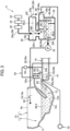
- FIG. 1 is a plan view of the flush toilet according to one embodiment of the present invention.
- FIG. 2 is a cross-sectional view along the line II-II of FIG. 1 .
- FIG. 3 is a schematic view showing an overall configuration of the flush toilet according to the present embodiment.
- a flush toilet 1 is a so-called "floor-standing flush toilet” in which a toilet main body 2 is disposed in contact on a floor surface F.
- the floor-standing flush toilet 1 of the present embodiment includes the toilet main body 2 made of ceramic and disposed in contact on the floor surface F and a flush water supply device 4 that supplies flush water to the toilet main body 2.
- the toilet main body 2 specifically includes a bowl 10 including a waste receiving surface 6 that receives waste and a rim 8 formed on a top edge of the waste receiving surface 6.
- the toilet main body 2 includes a discharge trap conduit 12 that forms a discharge flow channel that discharges waste inside the bowl 10.
- a functional part D including an electronic component of a warm water washing toilet seat device including a private part washing device that washes a private part of a user's body is provided.
- the discharge trap conduit 12 forms, from upstream toward downstream, a bent conduit having an inlet 12a connected to below the bowl 10, extending downward and rearward from the inlet 12a to a lowermost end portion 12b, then ascending upward and rearward to a top portion 12c, and descending downward and rearward from the top portion 12c.
- sealed water (sealed water surface WL0) is formed in a region upstream (forward) of the top portion 12c in the discharge trap conduit 12.
- an exit 12d downstream (rearward) of the bent conduit of the discharge trap conduit 12 is connected to a discharge pipe 16 on a back side of a wall W (or a front wall W of a cabinet C) via a discharge socket 14.
- the toilet main body 2 includes a rim spout part 18 including a rim spout port 18a provided in the rim 8.
- the rim spout port 18a is oriented toward an interior of the bowl 10.
- rim spout water W1 flush water supplied from the flush water supply device 4 to the toilet main body 2 (rim spout water W1) is spouted from the rim spout port 18a of the rim spout part 18 toward the interior of the bowl 10.
- a toilet bowl is flushed only with the rim spout water W1 spouted only from the rim spout port 18a. That is, the toilet bowl flushing is executed according to so-called "toilet bowl flushing with 100% rim spout water".
- FIG. 4 is a diagram schematically showing each configuration of the whole flush toilet according to the present embodiment and a flush water supply and discharge process.
- FIG. 5 is a cross-sectional view along the line V-V of FIG. 1 .
- FIG. 6 is a perspective view of the flush water supply device of the flush toilet according to the present embodiment viewed diagonally from behind, and
- FIG. 7 is a cross-sectional view along the line VII-VII of FIG. 6 .
- the flush water supply device 4 includes, from an external water supply source 22 such as water supply toward downstream, a stop cock 24, a valve unit 26, a water supply part 28, a reservoir tank 30, a pump 32, a rim side supply pipe 36, and an overflow pipe 40.
- the valve unit 26 which is not specifically described, includes a fixed flow valve (not shown), a diaphragm valve (not shown) that is an on-off valve provided downstream of the fixed flow valve (not shown), and an electromagnetic valve (not shown) that opens and closes the on-off valve (diaphragm valve).
- the flush water W0 passing through the valve unit 26 is supplied from the water supply part 28 into the reservoir tank 30 disposed behind and below the bowl 10 of the toilet main body 2.
- the flush water supply device 4 includes a controller (not shown) that controls the operation of the pump 32 disposed behind and below the bowl 10 of the toilet main body 2, and a float switch 42 that detects the water level in the reservoir tank 30.
- the opening and closing operation of the electromagnetic valve (not shown) of the valve unit 26 is controlled by the controller (not shown) based on the water level in the reservoir tank 30 detected by the float switch 42.
- the operation of the pump 32 is also controlled by the controller (not shown) based on the water level in the reservoir tank 30 detected by the float switch 42.
- the electromagnetic valve (not shown) of the valve unit 26 is opened, and the diaphragm valve (not shown) of the valve unit 26 is also opened.
- the supply water W0 is then supplied from the water supply part 28 to the reservoir tank 30.
- the flush water supply device 4 includes a toilet main body side connecting pipe 44 forming a conduit 44a (toilet main body side connecting conduit 44a) extending downstream through the pump 32 of the reservoir tank 30 from a first outflow port 30a below a prescribed water level (upper limit water level, full water level, first overflow water level) WL1.
- a toilet main body side connecting pipe 44 forming a conduit 44a (toilet main body side connecting conduit 44a) extending downstream through the pump 32 of the reservoir tank 30 from a first outflow port 30a below a prescribed water level (upper limit water level, full water level, first overflow water level) WL1.
- the rim spout water W1 of the flush water in the reservoir tank 30 is spouted from the rim spout port 18a of the toilet main body 2 through the pump 32.
- the reservoir tank 30 includes an overflow side connecting pipe 46 extending from an interior of the reservoir tank to a second outflow port 30b above the prescribed water level WL1 of the reservoir tank 30 and being connected to the overflow pipe 40.
- the overflow side connecting pipe 46 forms a conduit 46a (overflow side connecting conduit 46a) that communicates between the interior of the reservoir tank 30 and a flow channel 40a (overflow flow channel 40a) of the overflow pipe 40.
- the discharge trap conduit 12 of the toilet main body 2 includes a connecting member 12e connecting a downstream side of the discharge trap conduit 12 to an upstream side of the discharge socket 14, and the connecting member 12e forms a descending conduit 12f descending from the top portion 12c of the discharge trap conduit 12 to the downstream side (downward and rearward).
- the overflow pipe 40 of the flush water supply device 4 connects an outlet (second outflow port 30b) of the overflow side connecting pipe 46 to the upper surface of the descending conduit 12f of the discharge trap conduit 12.
- the first overflow flow channel 40a is disposed below the upper surface 8a of the rim 8 of the toilet main body 2, such that the flush water W2 (first overflow flush water W2) exceeding the prescribed water level WL1 in the reservoir tank 30 overflows into the descending conduit 12f of the discharge trap conduit 12 through the overflow pipe 40.
- the outlet of the overflow side connecting conduit 46a corresponds to the second outflow port 30b and is substantially a first overflow port 30b, and in the first overflow port 30b, a flapper valve 48 is openably/closably provided.
- the flapper valve 48 usually closes the first overflow port 30b, when the toilet bowl flushing is not performed during normal use.
- the flapper valve 48 can close the first overflow port 30b to prevent backflow of water in the discharge trap conduit 12 and can inhibit drop in flushing capacity.
- the flapper valve 48 is closed, such that discharge water is prevented from backflowing from a descending conduit 12f side of the discharge trap conduit 12 through the overflow flow channel 40a back into the overflow side connecting conduit 46a. It is also possible to prevent invasion of pests from an overflow flow channel 40a side into the overflow side connecting conduit 46a.
- the water supply part 28 of the flush water supply device 4 includes a water supply pipe 28a connected to the valve unit 26 upstream of the water supply part, a water supply nozzle 28b connected to the water supply pipe 28a, a water supply port 28c provided at a downstream end of the water supply nozzle 28b, and a water receiving housing 28d receiving flush water supplied from the water supply port 28c.
- the flush water W0 supplied from the water supply port 28c into the water receiving housing 28d is once received in the water receiving housing 28d and then flows from a communication path 28e between the water receiving housing 28d and the reservoir tank 30 into the reservoir tank 30.
- an opening 28f located above the first overflow port 30b of the reservoir tank 30 is provided.
- the opening 28f is disposed below the upper surface 8a of the rim 8 of the toilet main body 2.
- the opening 28f (second overflow port 28f) of the water receiving housing 28d has a lower end 28g located below the water supply port 28c. If the flush water in the reservoir tank 30 should rise into the water receiving housing 28d due to power failure, failure in the pump 32 or the like and reach the lower end 28g (second overflow water level WL3) of the opening 28f (second overflow port 28f), the second overflow port 28f can allow out-of-machine water leakage of flush water W3 (second overflow flush water W3).
- the second overflow port 28f of the water receiving housing 28d has an outer side provided with a second overflow flow channel 28h for the out-of-machine water leakage of the flush waterW3.
- the opening 28f (second overflow port 28f) of the water receiving housing 28d can thus provide an opening for atmospheric communication above the first overflow port 30b of the reservoir tank 30 and below the water supply port 28c, such that a space (air gap) can be provided between the water supply port 28c and the lower end 28g of the opening 28f (second overflow port 28f) preventing the water supply port 28c of the water supply part 28 from being submerged.
- the second overflow port 28f will be described in a form in which its height position is placed lower than the upper surface 8a of the rim 8 of the toilet main body 2.
- the height position of the second overflow port 28f may be placed above the upper surface 8a of the rim 8 of the toilet main body 2, provided that height positions of at least the first overflow flow channel 40a and first overflow port 30b are placed below the upper surface 8a of the rim 8 of the toilet main body 2 where the functional part D is disposed.
- the discharge socket 14 includes a body portion 14a connected to the exit 12d of the discharge trap conduit 12 of the toilet main body 2, and the body portion 14a connects the exit 12d of the descending conduit 12f of the discharge trap conduit 12 to an inlet 16a of the discharge pipe 16 at the rear of the body portion 14a.
- the body portion 14a forms a flow channel (internal flow channel) 14b inside, and the internal flow channel 14b has an upstream end as an inlet 14c connected to the exit 12d of the descending conduit 12f of the discharge trap conduit 12.
- the discharge socket 14 further includes a water reservoir on-off valve 50 openably/closably provided for the inlet 14c of the internal flow channel 14b in the body portion 14a and the exit 12d of the descending conduit 12f of the discharge trap conduit 12.
- the discharge socket 14 forms the discharge flow channel 14b downstream of the water reservoir on-off valve 50 and is attached to a part of the toilet main body 2.
- the water reservoir on-off valve 50 includes a rotary shaft 50a, a valve body 50b provided integrally on the rotary shaft 50a, and a mechanism part 50c that enables the rotary shaft 50a to rotate.
- the mechanism part 50c is coupled to an operation part 52 that enables user's manual opening and closing operation in case of emergency such as during the power failure.
- FIG. 7 shows the water reservoir on-off valve 50 in a state in which the exit 12d of the discharge trap conduit 12 is closed with a solid line, and in a state in which the exit is opened with a chain line.
- the valve body 50b rotates about the rotary shaft 50a in a rotating direction R1, such that the exit 12d of the discharge trap conduit 12 is usually opened.
- the user manually operates the operation part 52 to close the valve, such that water can be reserved in a flow channel in the discharge trap conduit 12 of the toilet main body 2 upstream of the water reservoir on-off valve 50 and a pooled water portion in the bowl 10.
- the water reservoir on-off valve 50 is provided downstream of the sealed water surface WL0 of the discharge trap conduit 12.
- an air vent tube 54 capable of removing air in a region A1 to the outside is connected between the sealed water surface WL0 in the discharge trap conduit 12 and the water reservoir on-off valve 50.
- the air vent tube 54 has an inlet 54a connected between the sealed water surface WL0 in the discharge trap conduit 12 and the water reservoir on-off valve 50 and an outlet 54b connected to the discharge flow channel 14b downstream of the water reservoir on-off valve 50 of the discharge socket 14.
- outlet 54b of the air vent tube 54 may be connected to a discharge flow channel such as the discharge pipe 16 connected to downstream of the discharge socket 14.
- the outlet 54b of the air vent tube 54 is disposed adjacent to the water reservoir on-off valve in a closed state so that the outlet is closed by flush water passing through an opened water reservoir on-off valve.
- the inlet 54a of the air vent tube 54 is connected to the overflow flow channel 40a as the inlet is disposed above an outlet 40b of the overflow pipe 40 (overflow flow channel 40a) that communicates with the descending conduit 12f of the lower discharge trap conduit 12.
- the air vent tube 54 rises curvedly from the inlet 54a toward an uppermost portion 54c, then descends curvedly from the uppermost portion 54c, and extends linearly downward to the outlet 54b.
- the inlet 54a and the uppermost portion 54c are arranged at positions higher than an uppermost portion 12g of the discharge trap conduit 12.
- the air vent tube 54 includes a check valve 56, and the check valve 56 allows passage of air A0 flow from an inlet 54a side of the air vent tube 54 toward an outlet 54b side, while blocking flow of air A0 from the outlet 54b side of the air vent tube 54 toward the inlet 54a side.
- the flush toilet 1 includes a plurality of overflow flow channels 40a and 28h for the flush water W2, W3 above the prescribed water level (upper limit water level, full water level, first overflow water level) WL1 in the reservoir tank 30 of the flush water supply device 4 to overflow at different locations, and the first overflow flow channel 40a of the plurality of overflow flow channels 40a and 28h can be disposed below the upper surface 8a of the rim 8 of toilet main body 2.
- the second overflow flow channel 28h of the plurality of overflow flow channels 40a and 28h has an inlet (second overflow port 28f) disposed above the first overflow flow channel 40a.
- the flush water W2 can reliably overflow from at least the first overflow flow channel 40a.
- the functional part D including an electronic component of a warm water washing toilet seat device including a private part washing device that washes a private part of a user's body is disposed above the upper surface 8a of the rear side of the rim 8 of the toilet main body 2, and the first overflow flow channel 40a itself is disposed below the upper surface 8a of the rim 8 of the toilet main body 2.
- the connecting portion such as the inlet 30b or the outlet 40b of the first overflow flow channel 40a due to aging, it is possible to reduce a risk of electric leakage due to water exposure of the electronic component of the functional unit D or the like.
- the inlet (second overflow port 28f) of the second overflow flow channel 28h is disposed above the first overflow flow channel 40a.
- the flush water W2 exceeding the prescribed water level (upper limit water level, full water level, first overflow water level) WL1 in the reservoir tank 30 further rises above the first overflow flow channel 40a and the first overflow port 30b, the flush water W3 can reliably overflow from the second overflow port 28f and the second overflow flow channel 28h (out-of-machine water leakage), before the raised flush water reaches the water supply port 28c of the water supply part 28 of the flush water supply device 4. Therefore, it is possible to reduce a risk that the water supply port 28c of the water supply part 28 of the flush water supply device 4 is submerged during power failure, at the time of failure or the like.
- the first overflow flow channel 40a and the first overflow port 30b can suppress the out-of-machine water leakage, and it is possible to reliably reduce a risk that the water supply port 28c of the water supply part 28 of the flush water supply device 4 is submerged in overflown flush water.
- the outlet 40b of the first overflow flow channel 40a and the second overflow port 28f of the second overflow flow channel 28h are connected to a location other than the bowl 10 of the toilet main body 2. Therefore, even if the interior of the bowl 10 of toilet main body 2 is clogged with waste, water can reliably overflow at the location other than the bowl 10 of the toilet main body 2 through at least one of the first overflow flow channel 40a and the second overflow flow channel 28h.
- the outlet 40b of the first overflow flow channel 40a is connected to a location (the descending conduit 12f of the discharge trap conduit 12) other than the flush water flow channel for use in toilet bowl flushing. Therefore, as compared with a case where the outlet 40b of the first overflow flow channel 40a is connected to the flush water flow channel for use in the toilet bowl flushing, the flush water W2 overflowing from the first overflow flow channel 40a can be inhibited from affecting the flush water of the flush water flow channel for use in the toilet bowl flushing, and hence a toilet bowl flushing performance can be ensured.
- a flow channel cross-sectional area of the first overflow flow channel 40a can be set to be larger, and an overflow performance can be improved.
- a water level required for cleaning the interior of the bowl 10 of the toilet main body 2 can be set low, and the low silhouette of the whole flush toilet 1 can be achieved.
- the outlet 40b of the first overflow flow channel 40a is connected to a discharge flow channel (descending conduit 12f) downstream of the discharge trap conduit 12 of the toilet main body 2. Therefore, even if an interior of the discharge trap conduit 12 of the toilet main body 2 upstream of the descending conduit 12f is clogged with waste or the like, the flush water W2 can reliably overflow from the descending conduit 12f of the discharge trap conduit 12 to the discharge pipe 16 through the first overflow flow channel 40a.
- the functional part D including the electronic component such as the warm water washing toilet seat device including the private part washing device that washes the private part of the user's body is disposed above the upper surface 8a of the rim 8 of the toilet main body 2, and all of the plurality of overflow flow channels 40a and 28h are arranged below the upper surface 8a of the rim 8 of the toilet main body 2.
- the connecting parts such as the inlets 30b, 28f, the outlet 40b and the like of any of the plurality of overflow flow channels 40a, 28h due to aging, it is possible to reduce the risk of the electric leakage due to the exposure of the electronic component of the functional part D to water.
- the low silhouette can be achieved in the whole flush toilet 1.
- the outlet 40b of the first overflow flow channel 40a is connected to the descending conduit 12f of the discharge trap conduit 12, and the second overflow flow channel 28h is disposed outside the second overflow port 28f of the water receiving housing 28d of the water supply part 28.
- the flow channels may only be connected to the location other than bowl 10 of the toilet main body 2 or to the location other than the flush water flow channel for use in toilet bowl flushing.
- a downstream side of each overflow flow channel 40a, 28h may be connected to the pooled water portion that forms the sealed water surface WL0 in the discharge trap conduit 12 or the discharge flow channel 14b in the discharge socket 14.
- the downstream side may be connected to the discharge pipe 16 or the like downstream of the discharge socket 14.
- flush toilet 1 a form of a "floor-standing flush toilet” in which the toilet main body 2 is disposed in contact on the floor surface F is adopted, and for a water discharge form, an example has been described in which the water discharge form by so-called “wall water discharge” including the exit 12d of the discharge trap conduit 12 connected to the discharge pipe 16 on the back side of the wall W (or the front wall W of the cabinet C) via the discharge socket 14 is adopted.
- wall water discharge including the exit 12d of the discharge trap conduit 12 connected to the discharge pipe 16 on the back side of the wall W (or the front wall W of the cabinet C) via the discharge socket 14 is adopted.
- the example is not limited to the water discharge form by the "wall water discharge”, and a water discharge form by so-called “floor water discharge” may be adopted in which the exit 12d of the discharge trap conduit 12 is connected to a discharge pipe disposed below the floor surface F via the discharge socket 14.
- a form of a so-called “wall mounted flush toilet” may be adopted in which the toilet main body 2 has a rear part fixed to the wall W of a toilet room T (or the front wall W of the cabinet C) and the rear part is spaced above the floor surface F.
- the present embodiment is also applicable to a so-called “hybrid flush toilet” in which flush water supplied under direct pressure from water supply is directly supplied as it is to the rim spout port 18a of the toilet main body 2, and flush water once supplied and stored in the reservoir tank 30 is supplied to a jet spout port of the toilet main body 2 by the pump 32.
Landscapes
- Engineering & Computer Science (AREA)
- Health & Medical Sciences (AREA)
- Life Sciences & Earth Sciences (AREA)
- Hydrology & Water Resources (AREA)
- Public Health (AREA)
- Water Supply & Treatment (AREA)
- Aviation & Aerospace Engineering (AREA)
- Sanitary Device For Flush Toilet (AREA)
Abstract
An object is to provide a flush toilet capable of suppressing out-of-machine water leakage and reliably reducing a risk that a water supply part is submerged in overflown flush water, while achieving low silhouette. A flush toilet 1 of the present invention includes a toilet main body 2, and a flush water supply device 4 that supplies flush water to this toilet main body, wherein this flush water supply device includes a water supply part 28 that supplies flush water W0 supplied from a water supply source 22, a reservoir tank 30 provided behind or below the toilet main body to store the flush water supplied from the water supply part, a pump 32 that sucks flush water in the reservoir tank 30 and causes the flush water to flow to the toilet main body, and a plurality of overflow flow channels 40a, 28h for flush water W2, W3 exceeding a prescribed water level WL1 in the reservoir tank to overflow at different locations, and at least one flow channel of the plurality of overflow flow channels is disposed below an upper surface 8a of a rim 8 of the toilet main body 2.
Description
- The present invention relates to a flush toilet and more particularly to a flush toilet which is flushed with flush water to discharge waste.
- Conventionally, as a flush toilet which is flushed with flush water to discharge waste, for example, a flush toilet comprising a plurality of overflow flow channels is known as described in
European Patent No. 3196370 andJapanese Patent No. 722241 Japanese Patent Laid-Open No. 2020-51236 - First, a conventional flush toilet described in
European Patent No. 3196370 is a so-called "wall mounted flush toilet" having a rear side of a toilet main body fixed to a wall surface and comprising the toilet main body and a flush water supply device supplying flush water to this toilet main body. - This flush water supply device includes a water supply part that supplies flush water supplied from a water supply source, a reservoir tank that stores the flush water supplied from this water supply part, and a pressurizing device that pressurizes flush water in the reservoir tank toward the toilet main body.
- The reservoir tank includes a tank body and an auxiliary tank, and the auxiliary tank is provided to communicate above the tank body so that flush water is supplied from the water supply part. Furthermore, an overflow port is formed on a top edge of the auxiliary tank, while a communication port communicating with the tank body is formed in a bottom portion of the auxiliary tank, and in this communication port, a valve body (water stop ball) is openably/closably provided.
- When the pressurizing device is inactive, the valve body opens the communication port of the auxiliary tank, such that flush water supplied from the water supply part to an interior of the auxiliary tank is supplied into the tank body from the communication port.
- When the pressurizing device is activated, the flush water in the tank body is pressurized by the pressurizing device and supplied to an interior of the toilet main body from a supply pipe connecting the tank body to the toilet main body, and the valve body closes the communication port of the auxiliary tank to prevent the flush water in the auxiliary tank from rising to the overflow port and from overflowing.
- Furthermore, in the conventional flush toilet described in
European Patent No. 3196370 , if flush water in the reservoir tank exceeds a prescribed water level due to power failure or failure in the pressurizing device, the flush water overflows through two overflow flow channels including a flow channel (first overflow flow channel) for the flush water in the tank body to overflow from the supply pipe to the toilet main body and a flow channel (second overflow flow channel) for the flush water in the tank body to overflow via the communication port of the auxiliary tank and the overflow port to an exterior of the toilet main body (so-called, "out-of-machine water leakage"). - In the conventional flush toilet described in
Japanese Patent No. 722241 Japanese Patent Laid-Open No. 2020-51236 - Such flush toilets as described above can comply, for example, with flush toilets according to European standards, even if it is necessary to provide the second overflow port open to the outside, in addition to the first overflow port connected to the overflow pipe.
- In the above-described conventional flush toilet described in
European Patent No. 3196370 described above, if a toilet bowl flushing operation is performed while a water supply part continues to supply water due to, for example, failure in the water supply part of a flush water supply device, there is a problem that water may leak outward from a reservoir tank through an overflow port (second overflow flow channel) of an auxiliary tank (out-of-machine water leakage). - Moreover, in the conventional flush toilet described in
European Patent No. 3196370 described above, in a first overflow flow channel for flush water in a tank body to overflow from a supply pipe to a toilet main body, there is a problem that such an overflow function cannot be performed, because the channel functions as a flush water flow channel essentially for use in flushing during toilet bowl flushing. - Next, in the conventional flush toilet described in
Japanese Patent No. 722241 Japanese Patent Laid-Open No. 2020-51236 - Furthermore, in the conventional flush toilet in
Japanese Patent No. 722241 Japanese Patent Laid-Open No. 2020-51236 - Additionally, in the conventional flush toilet described in
Patent Literature 2, a functional part including an electronic component such as a warm water washing toilet seat device including a private part washing device that washes a private part of a user's body is disposed above an upper surface of a rim of a toilet main body. In this case, there is a risk of electricity leakage due to exposure of the electronic component to flush water leakage from a connecting part of a first overflow flow channel due to aging or the like, or flush water leakage out of this machine through the second overflow port. - Therefore, in recent years, it has been a requested issue how to suppress the out-of-machine water leakage and how to reduce a risk that the water supply part of the flush water supply device is submerged in overflown flush water, while achieving the low silhouette in the whole flush toilet.
- An object of the present invention, which has been made to solve the above problems of conventional techniques and the recently requested issues, is to provide a flush toilet capable of suppressing out-of-machine water leakage and reliably reducing a risk that a water supply part is submerged in overflown flush water, while achieving low silhouette.
- To solve the above problems, according to the present invention, a flush toilet which is flushed with flush water to discharge waste is provided, the flush toilet including: a toilet main body including a bowl that receives waste, a rim formed on a top edge of the bowl, and a discharge trap conduit for discharging waste inside the bowl, and a flush water supply device that supplies flush water to the toilet main body, the flush water supply device includes a water supply part that supplies flush water supplied from a water supply source, a reservoir tank provided behind or below the toilet main body to store the flush water supplied from the water supply part, a pump that sucks flush water in the reservoir tank and causes the flush water to flow to the toilet main body, and a plurality of overflow flow channels for flush water exceeding a prescribed water level in the reservoir tank to overflow at different locations, and at least one flow channel of the plurality of overflow flow channels is disposed below an upper surface of the rim.
- According to the present invention, this configuration includes the plurality of overflow flow channels for flush water exceeding the prescribed water level in the reservoir tank of the flush water supply device to overflow at different locations, and at least one flow channel of the plurality of overflow flow channels can be disposed below the upper surface of the rim of the toilet main body.
- Consequently, even if the water level of the flush water in the reservoir tank of the flush water supply device provided behind or below the toilet main body rises above the prescribed water level, the flush water can reliably overflow through at least one overflow flow channel.
- In addition, for example, a functional part including an electronic component such as a warm water washing toilet seat device including a private part washing device that washes a private part of a user's body is disposed on the upper surface of the rim of the toilet main body. In this case, even if water leaks from a connecting part such as an inlet or outlet of at least one overflow flow channel due to aging, it is possible to reduce a risk of electricity leakage due to exposure of the electronic component to water, because the at least one overflow flow channel is disposed below the upper surface of the rim of the toilet main body.
- Furthermore, the flush water supply device includes the plurality of overflow flow channels, and even if the flush water exceeding the prescribed water level in the reservoir tank rises, the raised flush water can reliably overflow through the plurality of overflow flow channels before the raised flush water reaches the water supply part of the flush water supply device. Therefore, it is possible to reduce a risk of the water supply part of the flush water supply device being submerged in water during power failure, at the time of failure or the like.
- Furthermore, since at least one overflow flow channel of the plurality of overflow flow channels is disposed below the upper surface of the rim of the toilet main body, low silhouette can be achieved in the whole flush toilet.
- As a result, while achieving the low silhouette in the whole flush toilet, it is possible to suppress the out-of-machine water leakage and to reliably reduce the risk of the water supply part of the flush water supply device being submerged in overflown flush water.
- In the present invention, preferably, at least one flow channel of the plurality of overflow flow channels has an exit connected to a location other than the bowl of the toilet main body.
- In the present invention including this configuration, the exit of at least one flow channel of the plurality of overflow flow channels is connected to the location other than the bowl of the toilet main body. Therefore, even if an interior of the bowl of the toilet main body is clogged with waste, flush water can reliably overflow at the location other than the bowl of the toilet main body through at least one flow channel of the plurality of overflow flow channels.
- Therefore, it is possible to reduce the risk that the water supply part of the flush water supply device is submerged during the power failure, at the time of failure or the like.
- In the present invention, preferably, one overflow flow channel of the plurality of overflow flow channels has an exit connected to a location other than a flush water flow channel for use in toilet bowl flushing.
- In the present invention including this configuration, the exit of one overflow flow channel of the plurality of overflow flow channels is connected to the location other than the flush water flow channel for use in toilet bowl flushing. Therefore, as compared with a case where the exit of the overflow flow channel is connected to the flush water flow channel for use in the toilet bowl flushing, the flush water overflowing from one overflow flow channel can be inhibited from affecting the flush water of the flush water flow channel for use in the toilet bowl flushing, and hence a toilet bowl flushing performance can be ensured.
- Furthermore, as compared with the case where the exit of the overflow flow channel is connected to the flush water flow channel for use in the toilet bowl flushing, a flow channel cross-sectional area of the overflow flow channel can be set to be larger, and an overflow performance can be improved.
- Therefore, a water level required for cleaning an interior of the bowl of the toilet main body can be set low, and the low silhouette of the whole flush toilet can be achieved.
- In the present invention, preferably, one flow channel of the plurality of overflow flow channels has an exit connected to a discharge flow channel downstream of the discharge trap conduit of the toilet main body.
- In the present invention including this configuration, the exit of one flow channel of the plurality of overflow flow channels is connected to the discharge flow channel downstream of the discharge trap conduit of the toilet main body. Therefore, even if an interior of the discharge trap conduit of the toilet main body is clogged with waste or the like, the flush water can reliably overflow into the discharge flow channel through the overflow flow channel.
- Therefore, it is possible to reduce the risk that the water supply part of the flush water supply device is submerged during the power failure, at the time of failure or the like.
- In the present invention, preferably, all of the plurality of overflow flow channels are arranged below the upper surface of the rim.
- In the present invention including this configuration, for example, the functional part including the electronic component such as the warm water washing toilet seat device including the private part washing device that washes the private part of the user's body is disposed above the upper surface of the rim of the toilet main body, and all of the plurality of overflow flow channels are arranged below the upper surface of the rim of the toilet main body. In this case, even if water leaks from the connecting part such as the inlet or outlet of at least one overflow flow channel of the plurality of overflow flow channels due to aging, it is possible to reduce the risk of the electric leakage due to the exposure of the electronic component to water.
- In addition, the low silhouette can be achieved in the whole flush toilet.
- According to the flush toilet of the present invention, while achieving low silhouette, it is possible to suppress out-of-machine water leakage and to reliably reduce the risk that the water supply part is submerged in overflown flush water.
-
-
FIG. 1 is a plan view of a flush toilet according to one embodiment of the present invention; -
FIG. 2 is a cross-sectional view along the line II-II ofFIG. 1 ; -
FIG. 3 is a schematic view showing an overall configuration of the flush toilet according to one embodiment of the present invention; -
FIG. 4 is a diagram schematically showing each configuration of the whole flush toilet according to one embodiment of the present invention and a flush water supply and discharge process; -
FIG. 5 is a cross-sectional view along the line V-V ofFIG. 1 ; -
FIG. 6 is a perspective view of a flush water supply device of the flush toilet according to one embodiment of the present invention viewed diagonally from behind; and -
FIG. 7 is a cross-sectional view along the line VII-VII ofFIG. 6 . - Hereinafter, with reference to the accompanying drawings, a flush toilet according to one embodiment of the present invention will be described.
-
FIG. 1 is a plan view of the flush toilet according to one embodiment of the present invention.FIG. 2 is a cross-sectional view along the line II-II ofFIG. 1 .FIG. 3 is a schematic view showing an overall configuration of the flush toilet according to the present embodiment. - First, as shown in
FIGS. 1 and2 , aflush toilet 1 according to one embodiment of the present invention is a so-called "floor-standing flush toilet" in which a toiletmain body 2 is disposed in contact on a floor surface F. - Furthermore, as shown in
FIGS. 1 and2 , the floor-standingflush toilet 1 of the present embodiment includes the toiletmain body 2 made of ceramic and disposed in contact on the floor surface F and a flushwater supply device 4 that supplies flush water to the toiletmain body 2. - Next, as shown in
FIGS. 1 to 3 , the toiletmain body 2 specifically includes abowl 10 including awaste receiving surface 6 that receives waste and arim 8 formed on a top edge of thewaste receiving surface 6. - The toilet
main body 2 includes adischarge trap conduit 12 that forms a discharge flow channel that discharges waste inside thebowl 10. - Above an
upper surface 8a of a rear side of therim 8 of the toiletmain body 2, a functional part D including an electronic component of a warm water washing toilet seat device including a private part washing device that washes a private part of a user's body is provided. - Furthermore, as shown in
FIGS. 2 and3 , more specifically, thedischarge trap conduit 12 forms, from upstream toward downstream, a bent conduit having aninlet 12a connected to below thebowl 10, extending downward and rearward from theinlet 12a to alowermost end portion 12b, then ascending upward and rearward to atop portion 12c, and descending downward and rearward from thetop portion 12c. - As shown in
FIGS. 2 and3 , sealed water (sealed water surface WL0) is formed in a region upstream (forward) of thetop portion 12c in thedischarge trap conduit 12. - In the
flush toilet 1 of the present embodiment, anexit 12d downstream (rearward) of the bent conduit of thedischarge trap conduit 12 is connected to adischarge pipe 16 on a back side of a wall W (or a front wall W of a cabinet C) via adischarge socket 14. - Next, as shown in
FIGS. 2 and3 , the toiletmain body 2 includes arim spout part 18 including arim spout port 18a provided in therim 8. Therim spout port 18a is oriented toward an interior of thebowl 10. - As such, flush water supplied from the flush
water supply device 4 to the toilet main body 2 (rim spout water W1) is spouted from therim spout port 18a of therim spout part 18 toward the interior of thebowl 10. - That is, in the present embodiment, a toilet bowl is flushed only with the rim spout water W1 spouted only from the
rim spout port 18a. That is, the toilet bowl flushing is executed according to so-called "toilet bowl flushing with 100% rim spout water". - Next, with reference to
FIGS. 1 to 7 , the flushwater supply device 4 in theflush toilet 1 of the present embodiment will be described in detail. -
FIG. 4 is a diagram schematically showing each configuration of the whole flush toilet according to the present embodiment and a flush water supply and discharge process.FIG. 5 is a cross-sectional view along the line V-V ofFIG. 1 .FIG. 6 is a perspective view of the flush water supply device of the flush toilet according to the present embodiment viewed diagonally from behind, andFIG. 7 is a cross-sectional view along the line VII-VII ofFIG. 6 . - First, as shown in
FIGS. 1 to 3 , the flushwater supply device 4 includes, from an externalwater supply source 22 such as water supply toward downstream, astop cock 24, avalve unit 26, awater supply part 28, areservoir tank 30, apump 32, a rim side supply pipe 36, and anoverflow pipe 40. - First, the
valve unit 26, which is not specifically described, includes a fixed flow valve (not shown), a diaphragm valve (not shown) that is an on-off valve provided downstream of the fixed flow valve (not shown), and an electromagnetic valve (not shown) that opens and closes the on-off valve (diaphragm valve). - For example, when the diaphragm valve (not shown) is opened by operating the electromagnetic valve (not shown) of the
valve unit 26, flush water W0 (supply water W0) supplied from thewater supply source 22 via thestop cock 24 under supply water pressure of the water supply or the like passes through the fixed flow valve (not shown) of thevalve unit 26, has its flow rate adjusted to be constant, and then passes through the diaphragm valve (not shown). - Thus, the flush water W0 passing through the
valve unit 26 is supplied from thewater supply part 28 into thereservoir tank 30 disposed behind and below thebowl 10 of the toiletmain body 2. - Additionally, the flush
water supply device 4 includes a controller (not shown) that controls the operation of thepump 32 disposed behind and below thebowl 10 of the toiletmain body 2, and afloat switch 42 that detects the water level in thereservoir tank 30. - Furthermore, the opening and closing operation of the electromagnetic valve (not shown) of the
valve unit 26 is controlled by the controller (not shown) based on the water level in thereservoir tank 30 detected by thefloat switch 42. - The operation of the
pump 32 is also controlled by the controller (not shown) based on the water level in thereservoir tank 30 detected by thefloat switch 42. - For example, if the water level in the
reservoir tank 30 detected by thefloat switch 42 is predetermined or less, the electromagnetic valve (not shown) of thevalve unit 26 is opened, and the diaphragm valve (not shown) of thevalve unit 26 is also opened. The supply water W0 is then supplied from thewater supply part 28 to thereservoir tank 30. - Next, as shown in
FIGS. 3 ,5 and6 , the flushwater supply device 4 includes a toilet main bodyside connecting pipe 44 forming a conduit 44a (toilet main body side connecting conduit 44a) extending downstream through thepump 32 of thereservoir tank 30 from afirst outflow port 30a below a prescribed water level (upper limit water level, full water level, first overflow water level) WL1. - Consequently, when the
pump 32 is operated by the control of the controller (not shown) based on the water level in thereservoir tank 30 detected by thefloat switch 42, the flush water in thereservoir tank 30 flows out from thefirst outflow port 30a to the toilet main body side connecting conduit 44a, is sucked from thepump 32, and is supplied from the rim side supply pipe 36 to a rim conduit 36a. - Then, the rim spout water W1 of the flush water in the
reservoir tank 30 is spouted from therim spout port 18a of the toiletmain body 2 through thepump 32. - Then, as shown in
FIG. 3 , when the water level in thereservoir tank 30 rises and reaches a predetermined water level (stopped water level) WL2 below the prescribed water level WL1, the electromagnetic valve (not shown) of thevalve unit 26 is closed and the diaphragm valve (not shown) is closed based on detection of thefloat switch 42, such that the water supply of thewater supply part 28 is stopped and thepump 32 is stopped. - Next, as shown in
FIGS. 3 ,5 and6 , thereservoir tank 30 includes an overflow side connecting pipe 46 extending from an interior of the reservoir tank to asecond outflow port 30b above the prescribed water level WL1 of thereservoir tank 30 and being connected to theoverflow pipe 40. - The overflow side connecting pipe 46 forms a conduit 46a (overflow side connecting conduit 46a) that communicates between the interior of the
reservoir tank 30 and aflow channel 40a (overflow flow channel 40a) of theoverflow pipe 40. - As shown in
FIGS. 2 ,3 ,5 and7 , thedischarge trap conduit 12 of the toiletmain body 2 includes a connectingmember 12e connecting a downstream side of thedischarge trap conduit 12 to an upstream side of thedischarge socket 14, and the connectingmember 12e forms a descendingconduit 12f descending from thetop portion 12c of thedischarge trap conduit 12 to the downstream side (downward and rearward). - Furthermore, as shown in
FIGS. 2 ,3 ,5 and7 , theoverflow pipe 40 of the flushwater supply device 4 connects an outlet (second outflow port 30b) of the overflow side connecting pipe 46 to the upper surface of the descendingconduit 12f of thedischarge trap conduit 12. - As such, the first
overflow flow channel 40a is disposed below theupper surface 8a of therim 8 of the toiletmain body 2, such that the flush water W2 (first overflow flush water W2) exceeding the prescribed water level WL1 in thereservoir tank 30 overflows into the descendingconduit 12f of thedischarge trap conduit 12 through theoverflow pipe 40. - Furthermore, as shown in
FIGS. 2 ,3 ,5 and7 , the outlet of the overflow side connecting conduit 46a corresponds to thesecond outflow port 30b and is substantially afirst overflow port 30b, and in thefirst overflow port 30b, aflapper valve 48 is openably/closably provided. - The
flapper valve 48 usually closes thefirst overflow port 30b, when the toilet bowl flushing is not performed during normal use. - Also, when the toilet bowl flushing is performed, the
flapper valve 48 can close thefirst overflow port 30b to prevent backflow of water in thedischarge trap conduit 12 and can inhibit drop in flushing capacity. In addition, for example, even if thedischarge trap conduit 12 is clogged with water discharge, theflapper valve 48 is closed, such that discharge water is prevented from backflowing from a descendingconduit 12f side of thedischarge trap conduit 12 through theoverflow flow channel 40a back into the overflow side connecting conduit 46a. It is also possible to prevent invasion of pests from anoverflow flow channel 40a side into the overflow side connecting conduit 46a. - Furthermore, during abnormalities such as operation defects of the flush
water supply device 4 and stop due to power failure, if the water level in thereservoir tank 30 rises above the prescribed water level (upper limit water level, full water level, first overflow water level) WL1, fluid force of flush water forces theflapper valve 48 to open thefirst overflow port 30b. - This can prevent the flush water W2 flowing out of the
first overflow port 30b from backflowing from theoverflow flow channel 40a, such that the flush water can flow out (overflow) into the descendingconduit 12f of thedischarge trap conduit 12 of the toiletmain body 2. - Next, as shown in
FIGS. 3 ,5 and6 , thewater supply part 28 of the flushwater supply device 4 includes awater supply pipe 28a connected to thevalve unit 26 upstream of the water supply part, awater supply nozzle 28b connected to thewater supply pipe 28a, awater supply port 28c provided at a downstream end of thewater supply nozzle 28b, and awater receiving housing 28d receiving flush water supplied from thewater supply port 28c. - Since the
water receiving housing 28d is communicatively coupled to an upper part of thereservoir tank 30, the flush water W0 supplied from thewater supply port 28c into thewater receiving housing 28d is once received in thewater receiving housing 28d and then flows from acommunication path 28e between thewater receiving housing 28d and thereservoir tank 30 into thereservoir tank 30. - In a part of a side wall of the
water receiving housing 28d, anopening 28f (second overflow port 28f) located above thefirst overflow port 30b of thereservoir tank 30 is provided. Theopening 28f (second overflow port 28f) is disposed below theupper surface 8a of therim 8 of the toiletmain body 2. - The
opening 28f (second overflow port 28f) of thewater receiving housing 28d has alower end 28g located below thewater supply port 28c. If the flush water in thereservoir tank 30 should rise into thewater receiving housing 28d due to power failure, failure in thepump 32 or the like and reach thelower end 28g (second overflow water level WL3) of theopening 28f (second overflow port 28f), thesecond overflow port 28f can allow out-of-machine water leakage of flush water W3 (second overflow flush water W3). - Specifically, the
second overflow port 28f of thewater receiving housing 28d has an outer side provided with a second overflow flow channel 28h for the out-of-machine water leakage of the flush waterW3. - Therefore, a user can notice an emergency situation by the out-of-machine leakage water W3 from the
second overflow port 28f to the second overflow flow channel 28h. - For the flush
water supply device 4 of theflush toilet 1 according to the present embodiment to comply with overseas specifications such as European standards, theopening 28f (second overflow port 28f) of thewater receiving housing 28d can thus provide an opening for atmospheric communication above thefirst overflow port 30b of thereservoir tank 30 and below thewater supply port 28c, such that a space (air gap) can be provided between thewater supply port 28c and thelower end 28g of theopening 28f (second overflow port 28f) preventing thewater supply port 28c of thewater supply part 28 from being submerged. - Note that in the present embodiment, the
second overflow port 28f will be described in a form in which its height position is placed lower than theupper surface 8a of therim 8 of the toiletmain body 2. However, the height position of thesecond overflow port 28f may be placed above theupper surface 8a of therim 8 of the toiletmain body 2, provided that height positions of at least the firstoverflow flow channel 40a andfirst overflow port 30b are placed below theupper surface 8a of therim 8 of the toiletmain body 2 where the functional part D is disposed. - Next, with reference to
FIGS. 2 to 7 , thedischarge socket 14 will be described in detail. - As shown in
FIGS. 2 to 7 , thedischarge socket 14 includes abody portion 14a connected to theexit 12d of thedischarge trap conduit 12 of the toiletmain body 2, and thebody portion 14a connects theexit 12d of the descendingconduit 12f of thedischarge trap conduit 12 to aninlet 16a of thedischarge pipe 16 at the rear of thebody portion 14a. - The
body portion 14a forms a flow channel (internal flow channel) 14b inside, and theinternal flow channel 14b has an upstream end as aninlet 14c connected to theexit 12d of the descendingconduit 12f of thedischarge trap conduit 12. - The
discharge socket 14 further includes a water reservoir on-offvalve 50 openably/closably provided for theinlet 14c of theinternal flow channel 14b in thebody portion 14a and theexit 12d of the descendingconduit 12f of thedischarge trap conduit 12. - Consequently, the
discharge socket 14 forms thedischarge flow channel 14b downstream of the water reservoir on-offvalve 50 and is attached to a part of the toiletmain body 2. - The water reservoir on-off
valve 50 includes arotary shaft 50a, avalve body 50b provided integrally on therotary shaft 50a, and amechanism part 50c that enables therotary shaft 50a to rotate. Themechanism part 50c is coupled to anoperation part 52 that enables user's manual opening and closing operation in case of emergency such as during the power failure. -
FIG. 7 shows the water reservoir on-offvalve 50 in a state in which theexit 12d of thedischarge trap conduit 12 is closed with a solid line, and in a state in which the exit is opened with a chain line. During normal times, thevalve body 50b rotates about therotary shaft 50a in a rotating direction R1, such that theexit 12d of thedischarge trap conduit 12 is usually opened. - As shown in
FIG. 7 , for the water reservoir on-offvalve 50 in case of emergency such as during the power failure, the user manually operates theoperation part 52 to close the valve, such that water can be reserved in a flow channel in thedischarge trap conduit 12 of the toiletmain body 2 upstream of the water reservoir on-offvalve 50 and a pooled water portion in thebowl 10. - Next, as shown in
FIGS. 2 ,3 and5 to 7 , the water reservoir on-offvalve 50 is provided downstream of the sealed water surface WL0 of thedischarge trap conduit 12. - Furthermore, an
air vent tube 54 capable of removing air in a region A1 to the outside is connected between the sealed water surface WL0 in thedischarge trap conduit 12 and the water reservoir on-offvalve 50. - The
air vent tube 54 has aninlet 54a connected between the sealed water surface WL0 in thedischarge trap conduit 12 and the water reservoir on-offvalve 50 and anoutlet 54b connected to thedischarge flow channel 14b downstream of the water reservoir on-offvalve 50 of thedischarge socket 14. - Note that the
outlet 54b of theair vent tube 54 may be connected to a discharge flow channel such as thedischarge pipe 16 connected to downstream of thedischarge socket 14. - Furthermore, as shown in
FIG. 7 , theoutlet 54b of theair vent tube 54 is disposed adjacent to the water reservoir on-off valve in a closed state so that the outlet is closed by flush water passing through an opened water reservoir on-off valve. - Next, as shown in
FIG. 7 , theinlet 54a of theair vent tube 54 is connected to theoverflow flow channel 40a as the inlet is disposed above anoutlet 40b of the overflow pipe 40 (overflow flow channel 40a) that communicates with the descendingconduit 12f of the lowerdischarge trap conduit 12. - The
air vent tube 54 rises curvedly from theinlet 54a toward anuppermost portion 54c, then descends curvedly from theuppermost portion 54c, and extends linearly downward to theoutlet 54b. - For the
air vent tube 54, theinlet 54a and theuppermost portion 54c are arranged at positions higher than anuppermost portion 12g of thedischarge trap conduit 12. - As shown in
FIGS. 3 and7 , theair vent tube 54 includes acheck valve 56, and thecheck valve 56 allows passage of air A0 flow from aninlet 54a side of theair vent tube 54 toward anoutlet 54b side, while blocking flow of air A0 from theoutlet 54b side of theair vent tube 54 toward theinlet 54a side. - Next, with reference to
FIGS. 1 to 7 , an operation of theflush toilet 1 according to one embodiment of the present invention described above will be described. - First, the
flush toilet 1 according to one embodiment of the present invention includes a plurality ofoverflow flow channels 40a and 28h for the flush water W2, W3 above the prescribed water level (upper limit water level, full water level, first overflow water level) WL1 in thereservoir tank 30 of the flushwater supply device 4 to overflow at different locations, and the firstoverflow flow channel 40a of the plurality ofoverflow flow channels 40a and 28h can be disposed below theupper surface 8a of therim 8 of toiletmain body 2. - The second overflow flow channel 28h of the plurality of
overflow flow channels 40a and 28h has an inlet (second overflow port 28f) disposed above the firstoverflow flow channel 40a. - Consequently, even if the water level of flush water in the
reservoir tank 30 of the flushwater supply device 4 provided behind or below the toiletmain body 2 rises above the prescribed water level WL1, the flush water W2 can reliably overflow from at least the firstoverflow flow channel 40a. - Furthermore, in the
flush toilet 1 of the present embodiment, the functional part D including an electronic component of a warm water washing toilet seat device including a private part washing device that washes a private part of a user's body is disposed above theupper surface 8a of the rear side of therim 8 of the toiletmain body 2, and the firstoverflow flow channel 40a itself is disposed below theupper surface 8a of therim 8 of the toiletmain body 2. In this case, even if water leaks from a connecting portion such as theinlet 30b or theoutlet 40b of the firstoverflow flow channel 40a due to aging, it is possible to reduce a risk of electric leakage due to water exposure of the electronic component of the functional unit D or the like. - The inlet (
second overflow port 28f) of the second overflow flow channel 28h is disposed above the firstoverflow flow channel 40a. In this case, even if the flush water W2 exceeding the prescribed water level (upper limit water level, full water level, first overflow water level) WL1 in thereservoir tank 30 further rises above the firstoverflow flow channel 40a and thefirst overflow port 30b, the flush water W3 can reliably overflow from thesecond overflow port 28f and the second overflow flow channel 28h (out-of-machine water leakage), before the raised flush water reaches thewater supply port 28c of thewater supply part 28 of the flushwater supply device 4. Therefore, it is possible to reduce a risk that thewater supply port 28c of thewater supply part 28 of the flushwater supply device 4 is submerged during power failure, at the time of failure or the like. - Since both of the
overflow flow channels 40a and 28h are arranged below theupper surface 8a of therim 8 of the toiletmain body 2, low silhouette can be achieved in the wholeflush toilet 1. - As a result, while achieving the low silhouette in the whole
flush toilet 1, the firstoverflow flow channel 40a and thefirst overflow port 30b can suppress the out-of-machine water leakage, and it is possible to reliably reduce a risk that thewater supply port 28c of thewater supply part 28 of the flushwater supply device 4 is submerged in overflown flush water. - According to the
flush toilet 1 of the present embodiment, theoutlet 40b of the firstoverflow flow channel 40a and thesecond overflow port 28f of the second overflow flow channel 28h are connected to a location other than thebowl 10 of the toiletmain body 2. Therefore, even if the interior of thebowl 10 of toiletmain body 2 is clogged with waste, water can reliably overflow at the location other than thebowl 10 of the toiletmain body 2 through at least one of the firstoverflow flow channel 40a and the second overflow flow channel 28h. - Consequently, it is possible to reduce the risk that the
water supply port 28c of thewater supply part 28 of the flushwater supply device 4 is submerged during the power failure, at the time of failure or the like. - According to the
flush toilet 1 of the present embodiment, theoutlet 40b of the firstoverflow flow channel 40a is connected to a location (the descendingconduit 12f of the discharge trap conduit 12) other than the flush water flow channel for use in toilet bowl flushing. Therefore, as compared with a case where theoutlet 40b of the firstoverflow flow channel 40a is connected to the flush water flow channel for use in the toilet bowl flushing, the flush water W2 overflowing from the firstoverflow flow channel 40a can be inhibited from affecting the flush water of the flush water flow channel for use in the toilet bowl flushing, and hence a toilet bowl flushing performance can be ensured. - Furthermore, as compared with the case where the
outlet 40b of the firstoverflow flow channel 40a is connected to the flush water flow channel for use in the toilet bowl flushing (for example, the rim conduit 36a, therim spout part 18 or the like), a flow channel cross-sectional area of the firstoverflow flow channel 40a can be set to be larger, and an overflow performance can be improved. - Therefore, a water level required for cleaning the interior of the
bowl 10 of the toiletmain body 2 can be set low, and the low silhouette of the wholeflush toilet 1 can be achieved. - According to the
flush toilet 1 of the present embodiment, theoutlet 40b of the firstoverflow flow channel 40a is connected to a discharge flow channel (descendingconduit 12f) downstream of thedischarge trap conduit 12 of the toiletmain body 2. Therefore, even if an interior of thedischarge trap conduit 12 of the toiletmain body 2 upstream of the descendingconduit 12f is clogged with waste or the like, the flush water W2 can reliably overflow from the descendingconduit 12f of thedischarge trap conduit 12 to thedischarge pipe 16 through the firstoverflow flow channel 40a. - Therefore, it is possible to reduce the risk that the
water supply port 28c of thewater supply part 28 of the flushwater supply device 4 is submerged during the power failure, at the time of failure or the like. - According to the
flush toilet 1 of the present embodiment, the functional part D including the electronic component such as the warm water washing toilet seat device including the private part washing device that washes the private part of the user's body is disposed above theupper surface 8a of therim 8 of the toiletmain body 2, and all of the plurality ofoverflow flow channels 40a and 28h are arranged below theupper surface 8a of therim 8 of the toiletmain body 2. In this case, even if water leaks from the connecting parts such as theinlets outlet 40b and the like of any of the plurality ofoverflow flow channels 40a, 28h due to aging, it is possible to reduce the risk of the electric leakage due to the exposure of the electronic component of the functional part D to water. - In addition, the low silhouette can be achieved in the whole
flush toilet 1. - In the
flush toilet 1 according to the present embodiment described above, theoutlet 40b of the firstoverflow flow channel 40a is connected to the descendingconduit 12f of thedischarge trap conduit 12, and the second overflow flow channel 28h is disposed outside thesecond overflow port 28f of thewater receiving housing 28d of thewater supply part 28. Although this form has been described, for connection destinations downstream of theoverflow flow channels 40a and 28h, the flow channels may only be connected to the location other thanbowl 10 of the toiletmain body 2 or to the location other than the flush water flow channel for use in toilet bowl flushing. Specifically, a downstream side of eachoverflow flow channel 40a, 28h may be connected to the pooled water portion that forms the sealed water surface WL0 in thedischarge trap conduit 12 or thedischarge flow channel 14b in thedischarge socket 14. Alternatively, the downstream side may be connected to thedischarge pipe 16 or the like downstream of thedischarge socket 14. - Furthermore, in the
flush toilet 1 according to the present embodiment described above, a form of a "floor-standing flush toilet" in which the toiletmain body 2 is disposed in contact on the floor surface F is adopted, and for a water discharge form, an example has been described in which the water discharge form by so-called "wall water discharge" including theexit 12d of thedischarge trap conduit 12 connected to thedischarge pipe 16 on the back side of the wall W (or the front wall W of the cabinet C) via thedischarge socket 14 is adopted. - However, when "the floor-standing flush toilet" is adopted, the example is not limited to the water discharge form by the "wall water discharge", and a water discharge form by so-called "floor water discharge" may be adopted in which the
exit 12d of thedischarge trap conduit 12 is connected to a discharge pipe disposed below the floor surface F via thedischarge socket 14. - Instead of adopting the form of the "floor-standing flush toilet", a form of a so-called "wall mounted flush toilet" may be adopted in which the toilet
main body 2 has a rear part fixed to the wall W of a toilet room T (or the front wall W of the cabinet C) and the rear part is spaced above the floor surface F. - In the
flush toilet 1 of the present embodiment described above, the form in which so-called "toilet bowl flushing with 100% rim spout water" is executed only by rim spout water only from therim spout port 18a has been described. However, as a modification, a form is also applicable in which so-called "toilet bowl flushing by rim jet flushing " is executed by use of combination of the rim spout water W1 from therim spout port 18a of the toiletmain body 2 and jet spout water from a jet spout port. Even in this modification, it is preferable that all of the plurality ofoverflow flow channels 40a and 28h are arranged below theupper surface 8a of therim 8 of the toiletmain body 2. - Furthermore, as a modification of the
flush toilet 1 of the present embodiment described above, the present embodiment is also applicable to a so-called "hybrid flush toilet" in which flush water supplied under direct pressure from water supply is directly supplied as it is to therim spout port 18a of the toiletmain body 2, and flush water once supplied and stored in thereservoir tank 30 is supplied to a jet spout port of the toiletmain body 2 by thepump 32. -
- 1 flush toilet according to one embodiment of the present invention
- 2 toilet main body
- 4 flush water supply device
- 6 waste receiving surface
- 8 rim
- 8a upper surface of rim
- 10 bowl
- 12 discharge trap conduit
- 12a inlet of discharge trap conduit
- 12b lowermost end portion of discharge trap conduit
- 12c top portion of discharge trap conduit
- 12d exit of discharge trap conduit
- 12e connecting member of discharge trap conduit
- 12f descending conduit of discharge trap conduit
- 12g uppermost portion of discharge trap conduit
- 14 discharge socket
- 14a body portion of discharge socket
- 14b internal flow channel of discharge socket, discharge flow channel
- 14c inlet of internal flow channel of discharge socket
- 16 discharge pipe
- 16a inlet of discharge pipe
- 18 rim spout part
- 18a rim spout port
- 22 water supply source
- 24 stop cock
- 26 valve unit
- 28 water supply part
- 28a water supply pipe
- 28b water supply nozzle
- 28c water supply port
- 28d water receiving housing
- 28e communication path
- 28f opening, second overflow port
- 28g lower end of second overflow port
- 28h second overflow flow channel
- 30 reservoir tank
- 30a first outflow port
- 30b second outflow port, first overflow port, inlet of first
overflow flow channel 32 pump - 36 rim side supply pipe
- 36a rim conduit
- 40 overflow pipe
- 40a overflow flow channel
- 40b outlet of overflow flow channel
- 42 float switch
- 44 toilet main body side connecting pipe
- 44a toilet main body side connecting conduit
- 46 overflow side connecting pipe
- 46a overflow side connecting conduit
- 48 flapper valve
- 50 water reservoir on-off valve
- 50a rotary shaft
- 50b valve body
- 50c mechanism part
- 52 operation part
- 54 air vent tube
- 54a inlet of air vent tube
- 54b outlet of air vent tube
- 54c uppermost portion of air vent tube
- 56 check valve
- A0 air in region between sealed water surface and water reservoir on-off valve in discharge trap conduit
- A1 region between sealed water surface and water reservoir on-off valve in discharge trap conduit
- C cabinet
- D functional part of warm water washing toilet seat device
- F floor surface
- T toilet room
- W wall of toilet room or front wall of cabinet
- W0 supply water
- W1 rim spout water, rim flush water
- W2 first overflow flush water
- W3 second overflow flush water
- WL0 sealed water surface of bowl of toilet main body and discharge trap conduit
- WL1 prescribed water level in reservoir tank, upper limit water level, full water level, first overflow water level
- WL2 stopped water level in reservoir tank
- WL3 second overflow water level
Claims (5)
- A flush toilet which is flushed with flush water to discharge waste, comprising:a toilet main body including a bowl that receives waste, a rim formed on a top edge of the bowl, and a discharge trap conduit configured to discharge waste inside the bowl, anda flush water supply device that supplies flush water to the toilet main body, wherein the flush water supply device includes a water supply part that supplies flush water supplied from a water supply source, a reservoir tank provided behind or below the toilet main body to store the flush water supplied from the water supply part, a pump that sucks flush water in the reservoir tank and causes the flush water to flow to the toilet main body, and a plurality of overflow flow channels for flush water exceeding a prescribed water level in the reservoir tank to overflow at different locations, andat least one flow channel of the plurality of overflow flow channels is disposed below an upper surface of the rim.
- The flush toilet according to claim 1, wherein at least one flow channel of the plurality of overflow flow channels has an exit connected to a location other than the bowl of the toilet main body.
- The flush toilet according to claim 1 or 2, wherein one overflow flow channel of the plurality of overflow flow channels has an exit connected to a location other than a flush water flow channel for use in toilet bowl flushing.
- The flush toilet according to any one of claims 1 to 3, wherein one flow channel of the plurality of overflow flow channels has an exit connected to a discharge flow channel downstream of the discharge trap conduit of the toilet main body.
- The flush toilet according to any one of claims 1 to 4, wherein all of the plurality of overflow flow channels are arranged below the upper surface of the rim.
Applications Claiming Priority (1)
| Application Number | Priority Date | Filing Date | Title |
|---|---|---|---|
| JP2023141534A JP2025034871A (en) | 2023-08-31 | 2023-08-31 | Flush toilet |
Publications (1)
| Publication Number | Publication Date |
|---|---|
| EP4517014A1 true EP4517014A1 (en) | 2025-03-05 |
Family
ID=92214204
Family Applications (1)
| Application Number | Title | Priority Date | Filing Date |
|---|---|---|---|
| EP24192972.8A Pending EP4517014A1 (en) | 2023-08-31 | 2024-08-05 | Flush toilet |
Country Status (3)
| Country | Link |
|---|---|
| EP (1) | EP4517014A1 (en) |
| JP (1) | JP2025034871A (en) |
| CN (1) | CN119531463A (en) |
Citations (6)
| Publication number | Priority date | Publication date | Assignee | Title |
|---|---|---|---|---|
| JPH092241A (en) | 1995-06-14 | 1997-01-07 | Toyota Motor Corp | Vehicle body speed estimation device |
| EP1069250A2 (en) * | 1992-11-13 | 2001-01-17 | Kohler Co. | Pump operated plumbing fixture |
| EP3196370A1 (en) | 2016-01-22 | 2017-07-26 | Roca Sanitario, S. A. | Toilet flushing system |
| CN209323629U (en) * | 2018-08-03 | 2019-08-30 | 厦门瑞尔特卫浴科技股份有限公司 | A kind of overflow mechanism of low flush tank closestool |
| JP2020051236A (en) | 2018-09-20 | 2020-04-02 | Toto株式会社 | Water closet device |
| JP2023015321A (en) * | 2019-01-23 | 2023-01-31 | Toto株式会社 | Water closet |
-
2023
- 2023-08-31 JP JP2023141534A patent/JP2025034871A/en active Pending
-
2024
- 2024-07-26 CN CN202411009758.1A patent/CN119531463A/en active Pending
- 2024-08-05 EP EP24192972.8A patent/EP4517014A1/en active Pending
Patent Citations (6)
| Publication number | Priority date | Publication date | Assignee | Title |
|---|---|---|---|---|
| EP1069250A2 (en) * | 1992-11-13 | 2001-01-17 | Kohler Co. | Pump operated plumbing fixture |
| JPH092241A (en) | 1995-06-14 | 1997-01-07 | Toyota Motor Corp | Vehicle body speed estimation device |
| EP3196370A1 (en) | 2016-01-22 | 2017-07-26 | Roca Sanitario, S. A. | Toilet flushing system |
| CN209323629U (en) * | 2018-08-03 | 2019-08-30 | 厦门瑞尔特卫浴科技股份有限公司 | A kind of overflow mechanism of low flush tank closestool |
| JP2020051236A (en) | 2018-09-20 | 2020-04-02 | Toto株式会社 | Water closet device |
| JP2023015321A (en) * | 2019-01-23 | 2023-01-31 | Toto株式会社 | Water closet |
Also Published As
| Publication number | Publication date |
|---|---|
| CN119531463A (en) | 2025-02-28 |
| JP2025034871A (en) | 2025-03-13 |
Similar Documents
| Publication | Publication Date | Title |
|---|---|---|
| JP5013316B2 (en) | Flush toilet | |
| US8544123B2 (en) | Flush toilet | |
| JP5130802B2 (en) | Flush toilet | |
| JP5051611B2 (en) | Flush toilet | |
| US6219853B1 (en) | Toilet ventilation system | |
| US11624178B2 (en) | Flush toilet | |
| JP2023168489A (en) | Water closet | |
| JP5428462B2 (en) | Flush toilet | |
| JP5263704B2 (en) | Flush toilet | |
| US12612773B2 (en) | Flush toilet | |
| JP4305360B2 (en) | Toilet device | |
| EP4394140A1 (en) | Flush toilet | |
| JP5234484B2 (en) | Air bleed structure of flush toilet | |
| JP2009002075A (en) | Flush toilet bowl | |
| JP2008240402A (en) | Western-style water closet | |
| TW201430193A (en) | Automatic flushing system for toilet and electronic bidet toilet having the same | |
| JP2025034871A (en) | Flush toilet | |
| JP2025034872A (en) | Flush toilet | |
| JP4941892B2 (en) | Flush toilet | |
| EP4455416A1 (en) | Flush toilet | |
| JP7551054B2 (en) | Flush toilet equipment | |
| JP2026045785A (en) | flush toilet | |
| JP2025020926A (en) | Flush toilet equipment | |
| JP2024093852A (en) | Flush toilet | |
| JP2025132666A (en) | flush toilet |
Legal Events
| Date | Code | Title | Description |
|---|---|---|---|
| PUAI | Public reference made under article 153(3) epc to a published international application that has entered the european phase |
Free format text: ORIGINAL CODE: 0009012 |
|
| STAA | Information on the status of an ep patent application or granted ep patent |
Free format text: STATUS: REQUEST FOR EXAMINATION WAS MADE |
|
| 17P | Request for examination filed |
Effective date: 20240905 |
|
| AK | Designated contracting states |
Kind code of ref document: A1 Designated state(s): AL AT BE BG CH CY CZ DE DK EE ES FI FR GB GR HR HU IE IS IT LI LT LU LV MC ME MK MT NL NO PL PT RO RS SE SI SK SM TR |