EP4516992A2 - Pulpeur vertical de balles - Google Patents
Pulpeur vertical de balles Download PDFInfo
- Publication number
- EP4516992A2 EP4516992A2 EP24186708.4A EP24186708A EP4516992A2 EP 4516992 A2 EP4516992 A2 EP 4516992A2 EP 24186708 A EP24186708 A EP 24186708A EP 4516992 A2 EP4516992 A2 EP 4516992A2
- Authority
- EP
- European Patent Office
- Prior art keywords
- bale
- vertical
- pulper
- nose stopper
- vat
- Prior art date
- Legal status (The legal status is an assumption and is not a legal conclusion. Google has not performed a legal analysis and makes no representation as to the accuracy of the status listed.)
- Pending
Links
Images
Classifications
-
- D—TEXTILES; PAPER
- D21—PAPER-MAKING; PRODUCTION OF CELLULOSE
- D21B—FIBROUS RAW MATERIALS OR THEIR MECHANICAL TREATMENT
- D21B1/00—Fibrous raw materials or their mechanical treatment
- D21B1/04—Fibrous raw materials or their mechanical treatment by dividing raw materials into small particles, e.g. fibres
- D21B1/12—Fibrous raw materials or their mechanical treatment by dividing raw materials into small particles, e.g. fibres by wet methods, by the use of steam
- D21B1/30—Defibrating by other means
- D21B1/34—Kneading or mixing; Pulpers
- D21B1/345—Pulpers
-
- D—TEXTILES; PAPER
- D21—PAPER-MAKING; PRODUCTION OF CELLULOSE
- D21B—FIBROUS RAW MATERIALS OR THEIR MECHANICAL TREATMENT
- D21B1/00—Fibrous raw materials or their mechanical treatment
Definitions
- the present invention relates to vertical bale pulpers, especially in connection with pulp and fiber web production. More especially the invention relates to a vertical bale pulper according to the preamble part of claim 1.
- a typical production and treatment line comprises a forming section comprising a head box and a forming unit and a press section as well as a subsequent drying section and a reel-up.
- the production and treatment line can further comprise other devices and sections for finishing the fiber web, for example, a size press, a calender, a coating section.
- the production and treatment line also comprises typically at least one winder for forming customer rolls as well as a roll packaging apparatus.
- a treatment system of the fiber suspensions for example comprises a pulping section, a deashing system, a detrashing system, a coarse filtering section, a centrifugal cleaning section, a fractionation section, a fine filtering system, a fiber thickening system and fiber refining systems.
- a pulp mill is a manufacturing facility that converts wood chips or other plant fiber source into a mass of fibers. Pulp mills are not necessarily integrated with fiber web production, so such mills produce market pulp and sell it to fiber web production facilities. Market pulp is dried and then cut into sheets that are stacked into bales so they can be transported. The pulp sheets are commonly pressed into bales, having a weight which may be e.g. 200-250 kg.
- a pulp drying machine comprises typically a forming section, into which the stock to be dried is delivered by means of a headbox. After the forming section there is a press section, a dryer section, cutting section and bale formation and finally baling system. In the cutting section the web is slit in its machine direction into a number of partial webs which in turn are cut in cross direction into sheets, which are piled into bales.
- the bales are defibered to fiber pulp in bale pulpers; in vertical or horizontal pulpers for repulping of baled market pulps.
- a vertical pulper is typically used, when homogeneous slushing results with low energy consumption are needed, while a horizontal pulper, with its low height requirement, is typically used for rebuilds where limited space is available.
- the present invention relates to vertical bale pulpers for defibering pulp bales.
- the fiber suspension comprising typically about 95% water and 5% fiber is caused to a rotating flow by a rotor.
- the vertical bale pulper has a generally cylindrical form and in vertical bale pulpers orientation of the center axis of the cylindrical form of the vat is substantially vertical.
- the rotor located at the bottom of the pulper typically in a for example conical or dish end extension of the cylindrical form, causes a rotating flow inside the pulper. During the rotating flow caused by the rotor the fiber suspension is defibered.
- the pulper may be batch operated or continuous operating. Typically, in the batch operation every 20 seconds a bale is dropped and about 10 bales is dropped into the pulper for a defibration cycle in the pulper. A cycle takes typically about 15 minutes: 5 minutes for loading with the bales and the pulping liquid, 5 minutes for defibration and 5 minutes for emptying the pulper.
- Conveyor is used for transporting single bales, located sequentially in a queue on the conveyor, to a location at upper edge of a vertical bale pulper, from which location the bale is dropped into the pulper containing pulping liquid, typically water.
- the dropping of the bales into the pulper may cause impacts in the pulper structures and thus, the pulper structures, especially the rotor and its bearings, are at a risk of breaking, especially as during a day several hundreds of bales are typically handled in a vertical bale pulper.
- bale breakers it is known from prior art to use bale breakers to split a bale, when dropped into the pulper.
- the known bale brakers are formed of a beam element located across the diameter of the cylindrical form of the pulper such, that when the bale is dropped the beam element splits the bale and thus, decreases the impact of the bale in the pulper.
- the beam element is supported at its ends on the upper edge of the pulper and typically located at a distance below the upper edge of the pulper.
- the construction of these known bale brakers is thus rather complex and as being separate extra parts of the pulper increases the cost of the pulper. Also, the vertical location of the bale breaker must be taken in account in design of the pulper and the connected conveyor.
- bales might stick between the vertical wall of the pulper and the bale breaker and as for bales with wrappings the beam element is not always effective enough for the splitting of the bale. Additionally, in order to provide the splitting effect there needs to be a minimum drop height from the conveyor to the beam element.
- An object of the invention is to create a vertical bale pulper, in which the disadvantages and problems of prior art vertical bale pulper designs relating to bale breaking are eliminated or at least minimized.
- an object of the invention is to create a vertical bale pulper, in which the disadvantages and problems in respect of impacts on the pulper caused by bale dropping are eliminated or at least minimized.
- kinetic energy of the bale in the bale dropping causing impacts can be significantly reduced by a vertical baffle with a combined/integrated bale nose stopper at the top surface of the vertical baffle.
- a vertical baffle with a combined/integrated bale nose stopper at the top surface of the vertical baffle.
- the bale nose stopper When dropped the bale hits the bale nose stopper and thus, its kinetic energy is significantly reduced as the kinetic energy is passed to the support structures of the vertical bale pulper, advantageously to a support leg of the vertical pulper, in which case the bale nose stopper is located at location above the corresponding support leg.
- Vertical baffle/-s also called vertical deflector/- s located inside on the vertical wall of the pulper is/are used in the vertical bale pulpers to ensure flow towards the rotor and to prevent tangential flows of the fiber suspension inside the pulper in the vat.
- the bale nose stopper is advantageously located above the level of the fiber suspension in the vat and thus, the bale nose stopper does not cause disturbances in the fiber suspension flow inside the vertical bale pulper.
- the bale nose stopper reduced the kinetic energy of the bale, when the bale is dropped onto it as the bale nose stopper functions as a separate bale breaker element and thus, the lifetime of the rotor and the bearing unit of the rotor in the pulper is increased.
- the bale nose stopper integrated/combined to the vertical baffle can be provided to new construction pulpers and used in modernizing existing pulpers.
- the top surface of the bale nose stopper is advantageously downwards and towards the center of the vat inclined and thus, it also guides the bale downwards and towards the center of the vat.
- bale nose stopper combined with the vertical baffle is advantageously located at each of the conveyors.
- the vertical baffle/-s is/are attached on the vertical wall of the pulper vat by welding to ensure fast attachment and load bearing ability of the vertical baffle.
- the bale nose stopper is made of corrosion resistance steel, for example of acid-proof steel or stainless steel or Duplex stainless steel.
- the vertical baffle/-s is/are made of corrosion resistance steel, for example of acid-proof steel or stainless steel or Duplex stainless steel.
- the vertical bale pulper comprises a vat, which has a substantially cylindrical upper part and a downwards convergent lower part, a rotor at the bottom of the vat, a vertical wall surrounding the substantially cylindrical upper part, at least one vertical baffle extending vertically on the vertical wall inside of the vat, wherein the vertical bale pulper further comprises a bale nose stopper, the bale nose stopper is integrated on top of at least one of the vertical baffles.
- the bale nose stopper is located above level of fiber suspension in the vat of the vertical bale pulper.
- the bale nose stopper protrudes from the vertical wall inclinedly downwards towards the center of the vat and the inclination angle is advantageously 15-50 °, more advantageously 30-45 °.
- the vertical bale pulper comprises support legs and that the bale nose stopper is a located above one of the support legs of the vertical bale pulper.
- the bale nose stopper is integrated on top of the corresponding vertical baffle by welding.
- the bale nose stopper and the corresponding vertical baffle are integrated as one piece.
- cross-sectional size of the bale nose stopper is bigger than cross-sectional size of the vertical baffle integrated with the bale nose stopper.
- thickness of the bale nose stopper in radial direction is greater than thickness of the vertical baffle integrated with the bale nose stopper in radial direction.
- the upper surface of the bale nose stopper is substantially triangular and has three corners, and one of the corners is at lower level in vertical direction than at least one of the two other corners.
- the bale nose stopper is located under the conveyor.
- fiber suspension/-s means liquids and suspensions, which contain fibers to be defibered and possible other occurring ingredients.
- the fibers can be synthetic or non-synthetic fibers.
- the fibers in connection with this invention primarily mean newly produced cellulose fibers, but also recycled cellulose fibers can come into question if provided in bales to the process.
- the vertical bale pulper according to the invention is suitable for different types of fiber suspensions of synthetic and/or non-synthetic fiber material.
- figure 1 is schematically shown an advantageous example of a vertical bale pulper and a thereto connected loading conveyor.
- the vertical bale pulper 10 and the thereto connected conveyor 20.
- Bales B are transported on the conveyor 20 in a successive queue of the bales B.
- the conveyor 20 extends from a location (not shown) of loading the bales B onto the conveyor 20 vertically inclined to upper edge of the vertical bale pulper 10, to the location, where the bales B are singly dropped into the vertical bale pulper 10.
- the vertical bale pulper 10 has a vat 13 formed of an upper, substantially cylindrical part 13A and a lower, downwards convergent or dish end part 13B. At the bottom of the vat 13 of the vertical bale pulper 10 the rotor 11 is located.
- a screen plate 18 is located, though which the vertical bale pulper 10 is emptied, when the fiber suspension is ready and to be forwarded to further treatment, for example to refining.
- the vertical baffles 12, 12X have a triangular cross-section and they extend substantially vertically along the vertical wall 14 of the vertical bale pulper 10.
- the vertical baffles 12, 12X are located along the inner circumference of the vat 13 spaced apart.
- the triangular form extends as a protrusion towards the center of the vat 13.
- the vertical bale pulper 10 is supported by support legs 16 on a floor or like.
- bale nose stopper 30 One of the vertical baffles 12, the vertical baffle 12X to be located under the conveyor 20 is provided with the bale nose stopper 30.
- the upper surface of the bale nose stopper 30 on the side of the inner wall 14 of the vertical bale pulper 10 is located at a distance D from the upper edge of the vertical bale pulper 10 and the bale nose stopper 30 is located above the level L of fiber suspension in the vat 13 of the vertical bale pulper 10, when ready for defibrating or defibrating.
- the bale nose stopper 30 extends from the inner wall 14 inclinedly downwards towards the center of the vat 13 as a protrusion.
- the upper surface of the bale nose stopper 30 is substantially triangular and has three corners 31, 32, 33.
- the one of the corners 31, 32, 33 is at lower level in vertical direction than at least one of the two other corners 31, 32, 33.
- the inclination angle A is 15-50 °, advantageously 30-45 °.
- the top surface of the bale nose stopper 30 is advantageously downwards and towards the center of the vat 13 inclined and thus, it 30 also guides the bale B downwards and towards the center of the vat 13.
- the bale nose stopper 30 is advantageously located above one of the support legs 16 of the vertical bale pulper 10, to transfer the kinetic energy caused by the hit of the bale B from the bale nose stopper 30 via the corresponding support leg 16 to the floor 17.
- Cross-sectional size of the bale nose stopper 30 is the same or bigger than cross-sectional size of the vertical baffle 12X integrated with the bale nose stopper 30, as shown in the figure.
- the thickness X30 of the bale nose stopper 30 in radial direction is the same or greater than thickness X12 of the vertical baffle 12X integrated with the bale nose stopper 30 in radial direction, as shown in the figure.
- Height of the vertical baffle 12X with the integrated bale nose stopper 30 can be of same height than the other baffles 12 or higher.
- additional stiffeners can be located inside the vertical baffle 12X integrated with the bale nose stopper 30. In case the vertical bale pulper 10 is loaded via more than one conveyor the bale nose stopper 30 combined with the vertical baffle 12X is advantageously located at each of the conveyors.
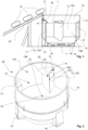
- figure 2 is further shown the example of the vertical bale pulper 10 according to figure 1 as a 3D view as a longitudinal cross-sectional view from side.
- the bales B are defibered to fiber pulp with homogeneous slushing result and with low energy consumption.
- the fiber suspension comprising typically about 95% water and 5% fiber is caused to the rotating flow by the rotor 11 and during the rotating flow caused by the rotor 11 the fiber suspension is defibered.
- the conveyor 20 is used for transporting the single bales B, located sequentially in a queue on the conveyor 20, to the location at upper edge of the vertical wall 14 of the vertical bale pulper 10, from which location one bale B at the time is dropped into the vat 13 of the vertical bale pulper 10 containing pulping liquid, typically water.
- bale nose stopper 30 When dropping a bale B into the vertical bale pulper 10 it first hits the bale nose stopper 30, which reduces the kinetic energy and thus, decreased the impact effect of the bale B in the pulper structures and thus, the risk of damage in the structures and parts of the vertical bale pulper 10 structures are eliminated.
- the construction of the bale nose stopper 30 is simple as can also be seen from the figures 1 and 2 and thus, its cost effect in production or in modernization of the vertical bale pulper 10 is minimized.
- the vertical location of the bale nose stopper 30 in the vertical bale pulper 10 is advantageous in view of the design of the vertical bale pulper 10 and the connected conveyor 20. Further, the bales B are not at any risk of sticking between the vertical wall 14 of the vertical bale pulper 10 and the bale nose stopper 30.
- the kinetic energy of the bale B in the bale dropping causing impacts is significantly reduced by the vertical baffle 12X with the combined/integrated bale nose stopper 30 at the top surface of the vertical baffle 12.
- the vertical baffle/-s 12, 12X located inside on the vertical wall 14 of the vertical bale pulper 10 to ensure flow towards the rotor 11 and to prevent tangential flows of the fiber suspension in the vat 13.
- the bale nose stopper 30 located above the level L of the fiber suspension in the vat 13 does not cause disturbances in the fiber suspension flow inside the vertical bale pulper 10.
- the vertical baffle/-s 12, 12X is/are attached on the vertical wall 14 of the vertical bale pulper 10 by welding to ensure fast attachment and load bearing ability of the vertical baffle 12, 12X.
- the bale nose stopper 30 can be a separate, but integrated part advantageously also welded on top of the corresponding vertical baffle 12X or the vertical baffle 12X and the bale nose stopper 30 can be produced as one piece.
Landscapes
- Engineering & Computer Science (AREA)
- Mechanical Engineering (AREA)
- Life Sciences & Earth Sciences (AREA)
- Wood Science & Technology (AREA)
- Paper (AREA)
Applications Claiming Priority (1)
| Application Number | Priority Date | Filing Date | Title |
|---|---|---|---|
| FI20235982A FI131484B1 (fi) | 2023-09-04 | 2023-09-04 | Pystysuuntainen paalipulpperi |
Publications (2)
| Publication Number | Publication Date |
|---|---|
| EP4516992A2 true EP4516992A2 (fr) | 2025-03-05 |
| EP4516992A3 EP4516992A3 (fr) | 2025-05-28 |
Family
ID=91853513
Family Applications (1)
| Application Number | Title | Priority Date | Filing Date |
|---|---|---|---|
| EP24186708.4A Pending EP4516992A3 (fr) | 2023-09-04 | 2024-07-05 | Pulpeur vertical de balles |
Country Status (3)
| Country | Link |
|---|---|
| EP (1) | EP4516992A3 (fr) |
| CN (1) | CN119553528A (fr) |
| FI (1) | FI131484B1 (fr) |
Citations (1)
| Publication number | Priority date | Publication date | Assignee | Title |
|---|---|---|---|---|
| DE202008000684U1 (de) | 2008-01-17 | 2009-05-20 | Voith Patent Gmbh | Stofflöser zur Zerkleinerung und Suspendierung von Papierstoff |
Family Cites Families (6)
| Publication number | Priority date | Publication date | Assignee | Title |
|---|---|---|---|---|
| EP0122991A3 (fr) * | 1982-08-12 | 1985-02-06 | The Black Clawson Company | Dispositif et procédé de desintégration de matières cellulosiques à haute densité |
| DE102005026108A1 (de) * | 2005-06-07 | 2006-12-14 | Voith Patent Gmbh | Stofflöser zur Zerkleinerung und Suspendierung von Papierstoff |
| CN207828668U (zh) * | 2017-12-25 | 2018-09-07 | 郑州运达造纸设备有限公司 | 一种散包机构及具有散包机构的水力碎浆机 |
| CN211471946U (zh) * | 2019-12-31 | 2020-09-11 | 郑州运达造纸设备有限公司 | 一种碎浆机投料结构 |
| CN216739039U (zh) * | 2021-11-05 | 2022-06-14 | 金红叶纸业(南通)有限公司 | 一种与水力碎浆机配套的散包装置 |
| CN218951842U (zh) * | 2022-12-26 | 2023-05-02 | 郑州磊展科技造纸机械有限公司 | 一种用于碎浆机的缓冲卸料装置 |
-
2023
- 2023-09-04 FI FI20235982A patent/FI131484B1/fi active
-
2024
- 2024-07-05 EP EP24186708.4A patent/EP4516992A3/fr active Pending
- 2024-08-14 CN CN202411115105.1A patent/CN119553528A/zh active Pending
Patent Citations (1)
| Publication number | Priority date | Publication date | Assignee | Title |
|---|---|---|---|---|
| DE202008000684U1 (de) | 2008-01-17 | 2009-05-20 | Voith Patent Gmbh | Stofflöser zur Zerkleinerung und Suspendierung von Papierstoff |
Also Published As
| Publication number | Publication date |
|---|---|
| FI131484B1 (fi) | 2025-05-13 |
| EP4516992A3 (fr) | 2025-05-28 |
| FI20235982A1 (en) | 2025-03-05 |
| CN119553528A (zh) | 2025-03-04 |
Similar Documents
| Publication | Publication Date | Title |
|---|---|---|
| US6214164B1 (en) | Process for pretreating wood chips for pulping | |
| US3925150A (en) | Selective reclamation of waste paper products | |
| US5324389A (en) | Waste paper disintegration, classification and pulping system | |
| EP0073609A2 (fr) | Tamis rotatif | |
| EP0473354A1 (fr) | Appareil de tamissage sous pression d'une suspension de fibres liquides | |
| US3236723A (en) | Sheet material reprocessing apparatus for paper broke | |
| US4619736A (en) | Apparatus for defiberizing, screening and pumping cellulose pulp or recycled paper | |
| EP4516992A2 (fr) | Pulpeur vertical de balles | |
| US3245868A (en) | Continuous process for the recovery of paper broke containing a wet strength resin | |
| EP2873769B1 (fr) | Désintégrateur à tambour | |
| US20250198082A1 (en) | Pulper for producing a stock suspension from solid particles and a flowable medium | |
| CA2323052C (fr) | Procede et appareil de traitement de suspensions fibreuses contenant des mineraux, telles que des casses de fabrication enduits, dans la production de papier | |
| EP2310567B1 (fr) | Triturateur de traitement d'une masse de fibres | |
| Blechschmidt et al. | Fibrous materials for paper and board manufacture | |
| FI103419B (fi) | Menetelmä ja laitteisto keräyskuitumateriaalin kuiduttamiseksi ja laji ttelemiseksi | |
| EP2873770B1 (fr) | Désintégrateur à tambour | |
| US5051151A (en) | Side extraction pulper with screw type rotor | |
| EP3260596B1 (fr) | Procédé de décendrage et système de décendrage | |
| FI131238B1 (en) | Drum in a drum pulper and drum pulper | |
| EP4650052A1 (fr) | Broyeur à fibres | |
| Somboon et al. | Grit Segments in TMP Refining-Part 2: Potential for Energy Reduction | |
| EP4575080A1 (fr) | Appareil de dispersion avec système de dilution | |
| CA2098516C (fr) | Machine a pate a papier | |
| Holik et al. | Stock preparation | |
| EP4644605A1 (fr) | Rotor de pulpeur |
Legal Events
| Date | Code | Title | Description |
|---|---|---|---|
| PUAI | Public reference made under article 153(3) epc to a published international application that has entered the european phase |
Free format text: ORIGINAL CODE: 0009012 |
|
| STAA | Information on the status of an ep patent application or granted ep patent |
Free format text: STATUS: THE APPLICATION HAS BEEN PUBLISHED |
|
| AK | Designated contracting states |
Kind code of ref document: A2 Designated state(s): AL AT BE BG CH CY CZ DE DK EE ES FI FR GB GR HR HU IE IS IT LI LT LU LV MC ME MK MT NL NO PL PT RO RS SE SI SK SM TR |
|
| PUAL | Search report despatched |
Free format text: ORIGINAL CODE: 0009013 |
|
| AK | Designated contracting states |
Kind code of ref document: A3 Designated state(s): AL AT BE BG CH CY CZ DE DK EE ES FI FR GB GR HR HU IE IS IT LI LT LU LV MC ME MK MT NL NO PL PT RO RS SE SI SK SM TR |
|
| RIC1 | Information provided on ipc code assigned before grant |
Ipc: D21B 1/34 20060101AFI20250423BHEP |
|
| STAA | Information on the status of an ep patent application or granted ep patent |
Free format text: STATUS: REQUEST FOR EXAMINATION WAS MADE |
|
| 17P | Request for examination filed |
Effective date: 20250704 |