EP4516991A1 - Crushed piece supply device and fiber structure manufacturing apparatus - Google Patents
Crushed piece supply device and fiber structure manufacturing apparatus Download PDFInfo
- Publication number
- EP4516991A1 EP4516991A1 EP24197350.2A EP24197350A EP4516991A1 EP 4516991 A1 EP4516991 A1 EP 4516991A1 EP 24197350 A EP24197350 A EP 24197350A EP 4516991 A1 EP4516991 A1 EP 4516991A1
- Authority
- EP
- European Patent Office
- Prior art keywords
- crushed piece
- space
- section
- supply device
- storage tank
- Prior art date
- Legal status (The legal status is an assumption and is not a legal conclusion. Google has not performed a legal analysis and makes no representation as to the accuracy of the status listed.)
- Pending
Links
Images



Classifications
-
- D—TEXTILES; PAPER
- D21—PAPER-MAKING; PRODUCTION OF CELLULOSE
- D21F—PAPER-MAKING MACHINES; METHODS OF PRODUCING PAPER THEREON
- D21F9/00—Complete machines for making continuous webs of paper
-
- D—TEXTILES; PAPER
- D21—PAPER-MAKING; PRODUCTION OF CELLULOSE
- D21C—PRODUCTION OF CELLULOSE BY REMOVING NON-CELLULOSE SUBSTANCES FROM CELLULOSE-CONTAINING MATERIALS; REGENERATION OF PULPING LIQUORS; APPARATUS THEREFOR
- D21C7/00—Digesters
- D21C7/06—Feeding devices
-
- D—TEXTILES; PAPER
- D21—PAPER-MAKING; PRODUCTION OF CELLULOSE
- D21B—FIBROUS RAW MATERIALS OR THEIR MECHANICAL TREATMENT
- D21B1/00—Fibrous raw materials or their mechanical treatment
- D21B1/02—Pretreatment of the raw materials by chemical or physical means
-
- D—TEXTILES; PAPER
- D21—PAPER-MAKING; PRODUCTION OF CELLULOSE
- D21B—FIBROUS RAW MATERIALS OR THEIR MECHANICAL TREATMENT
- D21B1/00—Fibrous raw materials or their mechanical treatment
- D21B1/04—Fibrous raw materials or their mechanical treatment by dividing raw materials into small particles, e.g. fibres
- D21B1/06—Fibrous raw materials or their mechanical treatment by dividing raw materials into small particles, e.g. fibres by dry methods
- D21B1/08—Fibrous raw materials or their mechanical treatment by dividing raw materials into small particles, e.g. fibres by dry methods the raw material being waste paper; the raw material being rags
-
- D—TEXTILES; PAPER
- D21—PAPER-MAKING; PRODUCTION OF CELLULOSE
- D21B—FIBROUS RAW MATERIALS OR THEIR MECHANICAL TREATMENT
- D21B1/00—Fibrous raw materials or their mechanical treatment
- D21B1/04—Fibrous raw materials or their mechanical treatment by dividing raw materials into small particles, e.g. fibres
- D21B1/12—Fibrous raw materials or their mechanical treatment by dividing raw materials into small particles, e.g. fibres by wet methods, by the use of steam
- D21B1/30—Defibrating by other means
- D21B1/34—Kneading or mixing; Pulpers
- D21B1/345—Pulpers
-
- D—TEXTILES; PAPER
- D21—PAPER-MAKING; PRODUCTION OF CELLULOSE
- D21C—PRODUCTION OF CELLULOSE BY REMOVING NON-CELLULOSE SUBSTANCES FROM CELLULOSE-CONTAINING MATERIALS; REGENERATION OF PULPING LIQUORS; APPARATUS THEREFOR
- D21C5/00—Other processes for obtaining cellulose, e.g. cooking cotton linters ; Processes characterised by the choice of cellulose-containing starting materials
- D21C5/02—Working-up waste paper
-
- D—TEXTILES; PAPER
- D21—PAPER-MAKING; PRODUCTION OF CELLULOSE
- D21G—CALENDERS; ACCESSORIES FOR PAPER-MAKING MACHINES
- D21G5/00—Safety devices
-
- Y—GENERAL TAGGING OF NEW TECHNOLOGICAL DEVELOPMENTS; GENERAL TAGGING OF CROSS-SECTIONAL TECHNOLOGIES SPANNING OVER SEVERAL SECTIONS OF THE IPC; TECHNICAL SUBJECTS COVERED BY FORMER USPC CROSS-REFERENCE ART COLLECTIONS [XRACs] AND DIGESTS
- Y02—TECHNOLOGIES OR APPLICATIONS FOR MITIGATION OR ADAPTATION AGAINST CLIMATE CHANGE
- Y02W—CLIMATE CHANGE MITIGATION TECHNOLOGIES RELATED TO WASTEWATER TREATMENT OR WASTE MANAGEMENT
- Y02W30/00—Technologies for solid waste management
- Y02W30/50—Reuse, recycling or recovery technologies
- Y02W30/64—Paper recycling
Definitions
- the present disclosure relates to a crushed piece supply device and a fiber structure manufacturing apparatus.
- a fiber structure manufacturing apparatus including a crushing section that crushes waste paper, a storing section that stores a crushed piece obtained by the crushing section, a defibrating section that defibrates the crushed piece discharged from the storing section, an accumulating section that accumulates, on a flat surface, a defibrated material obtained by the defibrating section, a heating and pressurizing section that heats and pressurizes an accumulated web, a cutting section that cuts a sheet obtained by the heating and pressurizing section into a predetermined shape, and a sheet collection section that collects an obtained sheet is known.
- Examples of the storing section include a storing section described in JP-A-2012-7246 .
- the storing section described in JP-A-2012-7246 includes a storage tank that stores a crushed piece and a humidifier that humidifies the crushed piece in the storage tank.
- a crushed piece supply device including a storage tank that stores a crushed piece containing a fiber and that has a first space and a second space positioned below the first space therein, an introduction port that communicates with the first space and through which the crushed piece is introduced into the first space, a partition portion that partitions an inside of the storage tank into the first space and the second space and that has a communication port which makes the first space and the second space communicate with each other, an adjusting section that adjusts a moving amount of the crushed piece moving from the first space to the second space via the communication port, a stirring section that stirs the crushed piece in the second space, and a discharge port through which the crushed piece stirred by the stirring section is discharged from the second space.
- a fiber structure manufacturing apparatus including the crushed piece supply device of the present disclosure, a defibrating section that defibrates the crushed piece supplied from the crushed piece supply device to generate a defibrated material, an accumulating section that accumulates the defibrated material to generate an accumulated material, and a molding section that molds the accumulated material.
- FIG. 1 is a configuration view showing an outline of the fiber structure manufacturing apparatus including the crushed piece supply device according to an embodiment of the present disclosure.
- FIG. 2 is a vertical sectional view of the crushed piece supply device shown in FIG. 1 .
- FIG. 3 is a cross-sectional view taken along line III-III in FIG. 2 .
- FIG. 4 is a cross-sectional view taken along line IV-IV in FIG. 2 .
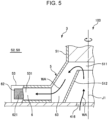
- FIG. 5 is an enlarged cross-sectional view of a stirring member and a shaft in FIG. 2 .
- FIG. 6 is a perspective view of the stirring member in FIG. 2 .
- FIGS. 1 , 2 , 5 , and 6 in some cases, an upper side will be referred to as “upper” or “upward”, and a lower side will be referred to as “lower” or “downward”.
- a left side of FIG. 2 will be referred to as “left” or “left side”
- a right side thereof will be referred to as “right” or “right side”.
- FIG. 1 is a schematic configuration view, and the positional relationship, the direction, the size, and the like of each section of a fiber structure manufacturing apparatus 100 are not limited to those shown.
- FIG. 1 is a schematic configuration view, and the positional relationship, the direction, the size, and the like of each section of a fiber structure manufacturing apparatus 100 are not limited to those shown.
- FIG. 1 is a schematic configuration view, and the positional relationship, the direction, the size, and the like of each section of a fiber structure manufacturing apparatus 100 are not limited to those shown.
- FIG. 1 is a schematic configuration view, and the positional relationship, the
- a direction in which a crushed piece M2, a defibrated material M3, a first sorted material M4-1, a second sorted material M4-2, a first web M5, a subdivided body M6, a mixture M7, a second web M8, and a sheet S are transported that is, a direction indicated by an arrow is also referred to as a transport direction.
- a tip side of the arrow in FIG. 1 is also referred to as "downstream" in the transport direction
- a base end side of the arrow in FIG. 1 is also referred to as "upstream" in the transport direction.
- the fiber structure manufacturing apparatus 100 shown in FIG. 1 is, for example, the fiber structure manufacturing apparatus 100 that generates the sheet S, which is an example of a fiber structure, from a raw material M1, which is waste paper such as used copy paper.
- the fiber structure manufactured by the fiber structure manufacturing apparatus 100 is not limited to the sheet S and may have a block shape.
- the fiber structure manufacturing apparatus 100 includes a raw material supply section 11, a crushing section 12, a crushed piece supply device 3 which is an example of the crushed piece supply device of the present disclosure, a defibrating device 13, a sorting section 14, a first web forming section 15, a subdividing section 16, a mixing section 17, a dispersion section 18, a second web forming section 19, a molding section 20, a severing section 21, a stock section 22, and a collection section 27.
- the fiber structure manufacturing apparatus 100 includes a humidifying section 231, a humidifying section 232, a humidifying section 233, a humidifying section 234, a humidifying section 235, and a humidifying section 236.
- the fiber structure manufacturing apparatus 100 includes a blower 261, a blower 262, and a blower 263.
- a raw material supply step, a crushing step, a crushed piece supply step, a defibration step, a sorting step, a first web forming step, a division step, a mixing step, a loosening step, a second web forming step, a sheet forming step, and a severing step are performed in this order.
- the raw material supply section 11 is a portion that performs the raw material supply step of supplying the raw material M1 to the crushing section 12.
- the raw material M1 is a sheet-like material made of a fiber-containing material containing cellulose fibers.
- the cellulose fiber may be a fibrous material containing cellulose, which is a compound, as a main component, and may contain hemicellulose and lignin in addition to the cellulose.
- the raw material M1 may be in any form, such as woven fabric and non-woven fabric.
- the raw material M1 may be, for example, recycled paper regenerated and manufactured by defibrating waste paper or YUPO paper (registered trademark) that is synthetic paper, or need not be recycled paper.
- the crushing section 12 is a portion that performs the crushing step of crushing, in the air such as in the atmosphere, the raw material M1 supplied from the raw material supply section 11.
- the crushing section 12 has a pair of crushing blades 121 and a chute 122.
- the raw material M1 By rotating the pair of crushing blades 121 in opposite directions to each other, the raw material M1 can be crushed therebetween, that is, cut into the crushed pieces M2.
- the shape and the size of the crushed piece M2 are suitable for defibration processing in the defibrating device 13.
- the shape of the crushed piece M2 include a small piece having a square planar shape and a small piece having a rectangular shape, particularly a strip shape.
- the size of the crushed piece M2 is preferably, for example, a small piece of which one side has an average length of 100 mm or less and more preferably 3 mm or more and 70 mm or less.
- the shape of the small piece may be other than a square shape or a rectangular shape.
- the thickness is 0.07 mm or more and 0.10 mm or less.
- the chute 122 is disposed below the pair of crushing blades 121 and has, for example, a conical shape or a funnel shape. Accordingly, the chute 122 can receive the crushed piece M2 that is crushed by the crushing blades 121 and is fallen.
- the humidifying section 231 is disposed adjacent to the pair of crushing blades 121.
- the humidifying section 231 humidifies the crushed piece M2 in the chute 122.
- the humidifying section 231 is configured as a vaporization type humidifier that has a filter (not shown) containing moisture and that supplies humidified air with an increased humidity to the crushed piece M2 by passing air through the filter.
- the chute 122 is coupled to the crushed piece supply device 3.
- the crushed piece M2 gathered by the chute 122 is sent and temporarily stored in the crushed piece supply device 3 and is supplied from the crushed piece supply device 3 to the defibrating device 13.
- the crushed piece supply device 3 performs the crushed piece supply step and supplies the crushed piece M2 to the defibrating device 13 as the crushed piece M2 is humidified.
- the crushed piece supply device 3 will be described in detail later.
- the defibrating device 13 is a portion that performs the defibration step of defibrating the crushed piece M2 in the air, that is, through a dry method.
- the defibrated material M3 can be generated from the crushed piece M2.
- “defibrating” refers to unraveling the crushed piece M2, which is formed by binding a plurality of fibers, into each strand of the fibers. Then, the unraveled material becomes the defibrated material M3.
- the shape of the defibrated material M3 is a linear shape or a belt shape.
- the defibrated materials M3 may be in a state of being intertwined with each other in a lump shape, that is, in a state of forming a so-called "lump".
- the defibrating device 13 can generate a flow of air from the crushed piece supply device 3 toward the sorting section 14, that is, an air flow, by the rotation of a rotor (not shown). Accordingly, the crushed piece M2 can be introduced upstream of the defibrating device 13 from a pipe 241, and after the defibration processing, the defibrated material M3 can be delivered to the sorting section 14 through a pipe 242.
- the pipe 242 is coupled downstream to the defibrating device 13.
- the blower 261 configured as, for example, a turbo type fan is installed in the middle of the pipe 242.
- the blower 261 is an air flow generation device that generates an air flow toward the sorting section 14. Accordingly, the introduction of the crushed piece M2 into the defibrating device 13 and the delivery of the defibrated material M3 to the sorting section 14 are promoted. Due to the structure of the defibrating device 13, passage and the defibration processing of the crushed piece M2, which is the raw material, are smoothly performed.
- blower 261 installed downstream of the defibrating device 13, the passage and the defibration processing of the crushed piece M2 in the defibrating device 13 are promoted.
- the blower 261 may be installed upstream of the defibrating device 13.
- the sorting section 14 is a portion that performs the sorting step of sorting the defibrated material M3 according to the size of a fiber length.
- the defibrated material M3 is sorted into the first sorted material M4-1 and the second sorted material M4-2 having a fiber length larger than that of the first sorted material M4-1.
- the first sorted material M4-1 has a size suitable for the subsequent manufacture of the sheet S.
- the second sorted material M4-2 includes, for example, a material insufficiently defibrated and a material in which defibrated fibers are excessively aggregated.
- the sorting section 14 has a drum portion 141 and a housing portion 142 that houses the drum portion 141.
- the drum portion 141 is configured as a cylindrical net body and is a sieve that rotates around a central axis thereof.
- the defibrated material M3 flows into the drum portion 141. Then, as the drum portion 141 rotates, the defibrated material M3 smaller than a mesh opening of the net is sorted as the first sorted material M4-1, and the defibrated material M3 having a size equal to or larger than the mesh opening of the net is sorted as the second sorted material M4-2.
- the first sorted material M4-1 falls from the drum portion 141.
- the second sorted material M4-2 is delivered to a pipe 243 coupled to the drum portion 141.
- An end portion of the pipe 243 on the opposite side, that is, downstream of the drum portion 141 is coupled to the middle of the pipe 241.
- the second sorted material M4-2 that has passed through the pipe 243 joins the crushed piece M2 in the pipe 241 and flows into the defibrating device 13 together with the crushed piece M2. Accordingly, the second sorted material M4-2 is returned to the defibrating device 13 and is subjected to the defibration processing together with the crushed piece M2.
- the first web forming section 15 is a portion that performs the first web forming step of forming the first web M5 with the first sorted material M4-1.
- the first web forming section 15 has a mesh belt 151, three tension rollers 152, and a suction section 153.
- the mesh belt 151 is an endless belt, and the first sorted material M4-1 is accumulated thereon.
- the mesh belt 151 is hung around the three tension rollers 152. Then, the first sorted material M4-1 on the mesh belt 151 is transported downstream by the rotational drive of the tension rollers 152.
- the first sorted material M4-1 has a size equal to or larger than the mesh opening of the mesh belt 151. Accordingly, the first sorted material M4-1 is restricted from passing through the mesh belt 151, and thereby can be accumulated on the mesh belt 151. In addition, the first sorted material M4-1 is transported downstream together with the mesh belt 151 as being accumulated on the mesh belt 151, so that the first sorted material M4-1 is formed as the layered first web M5.
- dust, dirt, or the like is mixed in the first sorted material M4-1.
- the dust or the dirt is generated by, for example, crushing or defibrating in some cases. Then, such dust or dirt is collected in the collection section 27 to be described later.
- the suction section 153 is a suction mechanism that sucks air from below the mesh belt 151. Accordingly, dust or dirt that has passed through the mesh belt 151 can be sucked together with air.
- suction section 153 is coupled to the collection section 27 via a pipe 244. Dust or dirt sucked by the suction section 153 is collected in the collection section 27.
- a pipe 245 is further coupled to the collection section 27.
- the blower 262 is installed in the middle of the pipe 245. By the operation of the blower 262, a suction force can be generated in the suction section 153. Accordingly, the formation of the first web M5 on the mesh belt 151 is promoted. The dust, the dirt, or the like is removed from the first web M5. In addition, the dust or the dirt passes through the pipe 244 and reaches the collection section 27 by the operation of the blower 262.
- the housing portion 142 is coupled to the humidifying section 232.
- the humidifying section 232 is configured as a vaporization type humidifier. Accordingly, humidified air is supplied into the housing portion 142.
- the first sorted material M4-1 can be humidified with the humidified air, and thereby adhesion of the first sorted material M4-1 to an inner wall of the housing portion 142 caused by an electrostatic force can also be suppressed.
- the humidifying section 235 is disposed downstream of the sorting section 14.
- the humidifying section 235 is configured as an ultrasonic humidifier that sprays water. Accordingly, moisture can be supplied to the first web M5, and thereby the amount of moisture of the first web M5 is adjusted. By this adjustment, the adsorption of the first web M5 to the mesh belt 151 caused by an electrostatic force can be suppressed. Accordingly, the first web M5 is easily peeled off from the mesh belt 151 at a position where the mesh belt 151 is folded back by the tension rollers 152.
- the subdividing section 16 is disposed downstream of the humidifying section 235.
- the subdividing section 16 is a portion that performs the division step of dividing the first web M5 peeled off from the mesh belt 151.
- the subdividing section 16 has a propeller 161 that is rotatably supported and a housing portion 162 that houses the propeller 161.
- the first web M5 can be divided by the rotating propeller 161.
- the divided first web M5 is the subdivided body M6.
- the subdivided body M6 descends in the housing portion 162.
- the housing portion 162 is coupled to the humidifying section 233.
- the humidifying section 233 is configured as a vaporization type humidifier. Accordingly, humidified air is supplied into the housing portion 162.
- the humidified air can also suppress adhesion of the subdivided body M6 to the propeller 161 or an inner wall of the housing portion 162 caused by an electrostatic force.
- the mixing section 17 is disposed downstream of the subdividing section 16.
- the mixing section 17 is a portion that performs the mixing step of mixing the subdivided body M6 and an additive.
- the mixing section 17 has an additive supply section 171, a pipe 172, and a blower 173.
- the pipe 172 is a flow passage that couples the housing portion 162 of the subdividing section 16 to a housing 182 of the dispersion section 18 and through which the mixture M7 of the subdivided bodies M6 and the additive passes.
- the additive supply section 171 is coupled to the middle of the pipe 172.
- the additive supply section 171 has a housing portion 170 that accommodates an additive and a screw feeder 174 that is provided in the housing portion 170. By the rotation of the screw feeder 174, the additive in the housing portion 170 is pushed out from the housing portion 170 and is supplied into the pipe 172. The additive supplied into the pipe 172 is mixed with the subdivided body M6 to become the mixture M7.
- examples of the additive supplied from the additive supply section 171 include a binder for binding fibers to each other, a coloring agent for coloring fibers, an agglomeration inhibitor for suppressing fiber agglomeration, a flame retardant for making fibers and the like unlikely to burn, and a paper strength enhancing agent for enhancing a paper strength of the sheet S, and one type or a plurality of types of additives, among these, can be used in combination.
- a binder P1 will be described.
- the additive includes a binder that binds fibers to each other, so that the strength of the sheet S can be increased.
- binder P1 examples include natural product-derived components, such as starch, dextrin, glycogen, amylose, hyaluronic acid, kudzu, konjac, potato starch, etherified starch, esterified starch, natural gum paste, fiber-inducing paste, seaweed, and animal protein, polyvinyl alcohol, polyacrylic acid, and polyacrylamide, and one type or two or more types selected from these can be used in combination.
- the natural product-derived components are preferable, and starch is more preferable.
- thermoplastic resins such as various types of polyolefins, acrylic resins, polyvinyl chloride, polyesters, and polyamides, and various types of thermoplastic elastomers can also be used.
- the blower 173 is installed downstream of the additive supply section 171.
- the action of a rotating portion such as a blade of the blower 173 promotes mixing of the subdivided body M6 and the binder P1.
- the blower 173 can generate an air flow toward the dispersion section 18.
- the subdivided body M6 and the binder P1 can be stirred in the pipe 172 by this air flow. Accordingly, in a state where the subdivided body M6 and the binder P1 are uniformly dispersed, the mixture M7 is transported to the dispersion section 18.
- the subdivided body M6 in the mixture M7 is loosened in the process of passing through the pipe 172 to be in a finer fibrous form.
- the blower 173 is electrically coupled to a control device 28, and the operation thereof is controlled. In addition, by adjusting the air blowing amount of the blower 173, the amount of air sent into a drum 181 can be adjusted.
- an end portion of the pipe 172 on a drum 181 side is bifurcated, and each of the bifurcated end portions is coupled to an introduction port (not shown) formed in an end surface of the drum 181.
- the dispersion section 18 shown in FIG. 1 is a portion that performs the loosening step of loosening and releasing fibers that are intertwined with each other in the mixture M7.
- the dispersion section 18 has the drum 181 that introduces and releases the mixture M7, which is the defibrated material, and the housing 182 that houses the drum 181.
- the drum 181 is configured as a cylindrical net body and is a sieve that rotates around a central axis thereof. As the drum 181 rotates, fibers or the like of the mixture M7, which are smaller than the mesh opening of the net, can pass through the drum 181. At that time, the mixture M7 is loosened and released together with air. That is, the drum 181 functions as a release section that releases a material containing fibers.
- the drum 181 is coupled to a driving source (not shown) and rotates with a rotational force output from the driving source.
- the driving source is electrically coupled to the control device 28, and the operation thereof is controlled.
- the housing 182 is coupled to the humidifying section 234.
- the humidifying section 234 is configured as a vaporization type humidifier. Accordingly, humidified air is supplied into the housing 182.
- the inside of the housing 182 can be humidified with the humidified air, and thus adhesion of the mixture M7 to the inner wall of the housing 182 caused by an electrostatic force can be suppressed.
- the second web forming section 19 is a portion that performs the second web forming step of accumulating the mixture M7 to form the second web M8 which is an accumulated material.
- the second web forming section 19 has a mesh belt 191, a tension roller 192, and a suction section 193.
- the mesh belt 191 is a mesh member and in the shown configuration, is configured as an endless belt.
- the mixture M7 dispersed and released by the dispersion section 18 is accumulated on the mesh belt 191.
- the mesh belt 191 is hung around the four tension rollers 192. Then, the mixture M7 on the mesh belt 191 is transported downstream by the rotational drive of the tension rollers 192.
- the present disclosure is not limited thereto, and for example, a flat plate shape may be used.
- most of the mixture M7 on the mesh belt 191 has a size equal to or larger than the mesh opening of the mesh belt 191. Accordingly, the mixture M7 is restricted from passing through the mesh belt 191 and thereby can be accumulated on the mesh belt 191. In addition, the mixture M7 is transported downstream together with the mesh belt 191 as being accumulated on the mesh belt 191, so that the layered mixture M7 is formed as the layered second web M8.
- the suction section 193 is a suction mechanism that sucks air from below the mesh belt 191. Accordingly, the mixture M7 can be sucked onto the mesh belt 191, and thereby the accumulation of the mixture M7 on the mesh belt 191 is promoted.
- a pipe 246 is coupled to the suction section 193.
- the blower 263 is installed in the middle of the pipe 246. By the operation of the blower 263, a suction force can be generated in the suction section 193.
- the humidifying section 236 is disposed downstream of the dispersion section 18.
- the humidifying section 236 is configured as an ultrasonic humidifier, like the humidifying section 235. Accordingly, moisture can be supplied to the second web M8, and thereby the amount of moisture of the second web M8 is adjusted. By this adjustment, the adsorption of the second web M8 to the mesh belt 191 caused by an electrostatic force can be suppressed. Accordingly, the second web M8 is easily peeled off from the mesh belt 191 at a position where the mesh belt 191 is folded back by the tension rollers 192.
- the total amount of moisture added to the humidifying section 231 to the humidifying section 236 is, for example, preferably 0.5 parts by mass or more and 20 parts by mass or less with respect to 100 parts by mass of a material before humidification.
- the molding section 20 is disposed downstream of the second web forming section 19.
- the molding section 20 is a portion that performs the sheet forming step of forming the sheet S from the second web M8.
- the molding section 20 has a pressurization section 201 and a heating section 202.
- the pressurization section 201 has a pair of calender rollers 203 and can pressurize the second web M8 between the calender rollers 203 without heating the second web M8. Accordingly, the density of the second web M8 is increased.
- the degree of heating in the case of heating is preferably a degree that the binder P1 is not melted, for example. Then, the second web M8 is transported toward the heating section 202.
- One of the pair of calender rollers 203 is a main roller driven by the operation of a motor (not shown), and the other is a driven roller.
- the heating section 202 has a pair of heating rollers 204 and can pressurize the second web M8 during heating the second web M8 between the heating rollers 204.
- the binder P1 is melted in the second web M8, and fibers are bound to each other via the melted binder P1. Accordingly, the sheet S is formed. Then, the sheet S is transported toward the severing section 21.
- One of the pair of heating rollers 204 is a main roller driven by the operation of a motor (not shown), and the other is a driven roller.
- the severing section 21 is disposed downstream of the molding section 20.
- the severing section 21 is a portion that performs the severing step of severing the sheet S.
- the severing section 21 has a first cutter 211 and a second cutter 212.
- the first cutter 211 severs the sheet S in a direction intersecting the transport direction of the sheet S, particularly a direction orthogonal to the transport direction.
- the second cutter 212 is located downstream of the first cutter 211 and severs the sheet S in a direction parallel to the transport direction of the sheet S. This severing is for removing unnecessary portions of both side end portions of the sheet S in a width direction to adjust the width of the sheet S.
- the sheet S having a desired shape and a desired size is obtained. Then, the sheet S is transported further downstream and is accumulated in the stock section 22.
- Each section included in such a fiber structure manufacturing apparatus 100 is electrically coupled to the control device 28. The operation of each of these sections is controlled by the control device 28.
- the discharge port 412 is provided in the bottom portion of the storage tank 41, that is, a side surface of a lower portion of the storage tank 41.
- the crushed piece M2 in the second space S2 is discharged from the discharge port 412 as being stirred by the operation of the stirring section 5 to be described later.
- the pipe 241 is coupled to the discharge port 412, and the crushed piece M2 discharged from the discharge port 412 is supplied to the defibrating device 13 shown in FIG. 1 via the pipe 241 and is defibrated.
- the discharge port 412 is provided in the bottom portion of the storage tank 41. Accordingly, the crushed piece M2 can be efficiently discharged from the discharge port 412 as being stirred.
- the discharge port 412 may be provided in a bottom surface of the storage tank 41 or may be provided at another position.
- the partition portion 42 is configured as a member having a conical or funnel-shaped hole of which an inner diameter decreases as going downward. That is, the partition portion 42 has a communication port 421 below. A shaft 51 to be described later is inserted into the communication port 421 without contact. An edge portion of the communication port 421 and the shaft 51 are separated from each other by a predetermined distance. Therefore, the crushed piece M2 can be moved from the first space S1 to the second space S2 via the communication port 421 by the rotation of a first stirring member 52 to be described later.
- the partition portion 42 has an inclined surface 422 positioned on a first space S1 side.
- the inclined surface 422 is inclined such that the communication port 421 is at the bottom.
- the inclined surface 422 has a shape along the shape of an upper surface of the partition portion 42 and has, for example, a conical shape or a funnel shape surrounding the entire circumference of an outer circumferential portion of the communication port 421.
- the shape of the inclined surface 422 is not limited to the above and may be, for example, a pyramidal shape surrounding the entire circumference of the outer circumferential portion of the communication port 421, or the inclined surface 422 may be a pair of inclined flat surfaces disposed each on the right and left of the shaft 51.
- An average inclination angle of the inclined surface 422 is not particularly limited and is preferably 15° or more and 80° or less and more preferably 25° or more and 70° or less with respect to a central axis J1 of the rotation of the shaft 51. With such a range, the crushed piece M2 can be more smoothly guided to the communication port 421.
- the partition portion 42 has the inclined surface 422 that is positioned on the first space S1 side and that is inclined such that the communication port 421 is at the bottom. Accordingly, the crushed piece M2 in the first space S1 can be smoothly guided to the communication port 421.
- the humidified air exhaust space S3 is a space that communicates with the second space S2 and the exhaust port 413.
- the humidified air exhaust space S3 includes a space formed by the flow passage forming member 43.
- the flow passage forming member 43 is a member that couples through-holes 414 and 415 formed in the storage tank 41.
- the through-hole 414 is formed at a second space S2 side of a side wall of the storage tank 41, that is, below the partition portion 42, and the through-hole 415 is formed in the side wall of the storage tank above the first space S141. That is, the through-hole 414 and the through-hole 415 are formed in the side wall of the storage tank 41 to be arranged in this order from the lower side.
- the flow passage forming member 43 is a member that hermetically covers a portion between the through-holes 414 and 415, among the through-holes 414 and 415 and the outer circumferential portion of the storage tank 41.
- Humidified air WA released to the second space S2 by the humidifying section 6 to be described later is used in humidifying the crushed piece M2 that is being stirred by the stirring section 5, but some of the humidified air WA enters the first space S1 through the communication port 421 and slightly humidifies the crushed piece M2 in the first space S1.
- a surplus portion of the humidified air WA released to the second space S2 passes through the humidified air exhaust space S3 from the second space S2, further crosses an upper portion of the first space S1 from the left to the right, and is discharged from the exhaust port 413 to the outside of the storage tank 41.
- an auxiliary flow passage (not shown) or a bypass flow passage (not shown) may be provided at the upper portion of the storage tank 41.
- a configuration where the surplus portion of the humidified air WA may be discharged to the outside of the storage tank 41 without crossing the first space S1 may be adopted.
- a configuration where the exhaust port 413 is provided in an upper end portion of the flow passage forming member 43, that is, a top surface of the storage tank 41 can be adopted.
- the humidified air exhaust space S3 also communicates with the first space S1 on the upper side. Accordingly, the surplus portion of the humidified air WA that is moved from the second space S2 to the first space S1 via the communication port 421 is moved from the first space S1 to the humidified air exhaust space S3 and is discharged from the exhaust port 413.
- the stirring section 5 has the shaft 51, the first stirring member 52, and a second stirring member 53 (stirring member).
- the shaft 51 has a rod shape extending in an up-down direction in FIG. 2 , that is, a vertical direction from the bottom portion of the storage tank 41.
- the shaft 51 rotates around the central axis J1 along the vertical direction.
- An end portion of the shaft 51 on the lower side is coupled to the motor M.
- the shaft 51 rotates by the operation of the motor M.
- the motor M rotates in one direction, that is, an arrow direction in FIG. 2 . Accordingly, the shaft 51 rotates clockwise in FIGS. 3 and 4 .
- the disclosure is not limited to the configuration, and the shaft 51 may be configured to be rotatable in either a forward or reverse direction.
- a speed reducer may be installed between the motor M and the shaft 51.
- the motor M is electrically coupled to the control section 281 of the control device 28 shown in FIG. 1 , and an energization condition is controlled by the control section 281. Accordingly, the shaft 51 rotates at a predetermined timing and a predetermined rotation speed.
- the shaft 51 is inserted through the communication port 421 of the partition portion 42.
- An upper end portion of the shaft 51 is positioned in the first space S1.
- the first stirring member 52 is provided at an outer circumferential portion of the shaft 51 in the first space S1
- the second stirring member 53 is provided at the outer circumferential portion of the shaft 51 in the second space S2.
- the first stirring member 52 stirs the crushed piece M2 in the first space S1 by rotating together with the shaft 51.
- the first stirring member 52 has a plate shape, particularly a strip shape, in which a circumferential direction of the shaft 51 is a thickness direction.
- a plurality of, in the present embodiment, four first stirring members 52 are provided at equal intervals (equal angular intervals).
- the disclosure is not limited to the configuration, and the first stirring member 52 may have a rod shape.
- the number of installations is also not limited to four and may be one to three or five or more.
- the respective first stirring members 52 may not be disposed at equal intervals.
- the crushed piece M2 As the first stirring member 52 stirs the crushed piece M2 in the first space S1, the crushed piece M2 is loosened, and the entanglement of each sheet can be unraveled.
- the crushed piece M2 broken in such a manner can smoothly move to the second space S2 via the communication port 421.
- the second stirring member 53 stirs the crushed piece M2 in the second space S2 by rotating together with the shaft 51.
- the second stirring member 53 is disposed at a position shifted to a bottom portion side of the storage tank 41.
- the second stirring member 53 has a plate shape, particularly a strip shape, in which the circumferential direction of the shaft 51 is the thickness direction.
- a plurality of, in the present embodiment, four second stirring members 53 are provided at equal intervals (equal angular intervals).
- the disclosure is not limited to the configuration, and the second stirring member 53 may have a rod shape.
- the number of installations is also not limited to four and may be one to three or five or more.
- the respective second stirring members 53 may not be disposed at equal intervals.
- the second stirring member 53 rotates around the central axis J1 and stirs the crushed piece M2, the crushed piece M2 is loosened, and the entanglement of each sheet can be unraveled.
- the second stirring member 53 can push out the crushed piece M2 forward in a rotation direction of the shaft 51. Accordingly, the crushed piece M2 can be smoothly discharged from the discharge port 412.
- the first stirring member 52 and the second stirring member 53 can stir by collectively rotating in response to the rotation of the shaft 51. Accordingly, the discharge of the crushed piece M2 from the second space S2 by the second stirring member 53 and the movement (replenishment) of the crushed piece M2 to the second space S2 by the first stirring member 52 can be collectively performed by one power mechanism.
- first stirring member 52 and the second stirring member 53 may be configured to rotate independently of each other.
- the crushed piece supply device 3 includes the partition portion 42 that partitions the internal space S0 into the first space S1 and the second space S2 positioned below the first space S1, and the second stirring member 53, which is the stirring member, is provided in the second space S2 and stirs the crushed piece M2 moved from the first space S1 to the second space S2. Accordingly, in a state where the entanglement of the crushed piece M2 in the second space S2 is loosened, the crushed piece M2 can be smoothly discharged from the crushed piece supply device 3.
- the second stirring member 53 which is the stirring member, is installed at the bottom portion of the storage tank 41 and rotates in one direction around the central axis J1 along the vertical direction. Accordingly, the crushed piece M2 in the internal space S0, particularly in the second space S2 can be stably discharged from the crushed piece supply device 3.
- the stirring section 5 is disposed at the outer circumferential portion of the shaft 51 in the second space S2 and has a plurality of (in the present embodiment, four) second stirring members 53 that rotate together with the shaft 51. Accordingly, the crushed piece M2 in the second space S2 can be well stirred.
- the humidifying section 6 has a humidified air supply source 61, a humidified air release port 62, a humidified air supply passage 63, an air blowing fan 64, and a valve 65.
- the humidifying section 6 humidifies the crushed piece M2 in the internal space S0, particularly, the crushed piece M2 in the second space S2. Accordingly, an electrostatic force can prevent the crushed pieces M2 from being entangled with each other or the crushed pieces M2 from adhering to each part in the storage tank 41. Accordingly, the crushed piece M2 can be smoothly and stably discharged from the discharge port 412, and the subsequent processing, for example, the defibration processing and the next step, such as quantitative supply, can be appropriately and well performed.
- the crushed piece supply device 3 includes the humidifying section 6 that humidifies the crushed piece M2 in the storage tank 41, particularly the crushed piece M2 in the second space S2. Accordingly, the crushed piece M2 in the internal space S0, particularly in the second space S2 can be efficiently humidified. As a result, the entanglement of the crushed pieces M2 with each other and the adhesion of the crushed pieces M2 to the inside of the device caused by an electrostatic force can be effectively prevented.
- the humidified air supply source 61 shown in FIG. 2 generates the humidified air WA.
- the humidified air supply source 61 generates the humidified air WA through, for example, a vaporization method or an ultrasonic method.
- a power supply (a main power supply, the same applies hereinafter) of the fiber structure manufacturing apparatus 100 is turned off, the humidified air supply source 61 stops the generation of the humidified air WA, and when the power supply of the fiber structure manufacturing apparatus 100 is turned on, the humidified air supply source 61 starts the generation of the humidified air WA.
- the air blowing fan 64 that blows the humidified air WA toward the humidified air release port 62 and the valve 65 that adjusts the flow rate of the humidified air WA are installed.
- the humidified air WA generated by the humidified air supply source 61 is transferred to each humidified air release port 62 through the humidified air supply passage 63 by the operation of the air blowing fan 64 and is released.
- the air blowing fan 64 is configured as, for example, a blower, and the valve 65 is configured as, for example, an electromagnetic valve having a variable opening degree.
- Each of the humidified air supply source 61, the air blowing fan 64, and the valve 65 is electrically coupled to the control section 281 of the control device 28 shown in FIG. 1 , and the energization condition is controlled by the control section 281. Accordingly, the humidified air WA is released from the humidified air release port 62 at a predetermined timing, a predetermined humidity, and a predetermined flow rate and is supplied to the crushed piece M2.
- the humidifying section 6 may have a configuration of not having any one or both of the air blowing fan 64 and the valve 65.
- the humidified air release port 62 is provided in the second stirring member 53 and releases the humidified air WA toward the crushed piece M2 stirred by the second stirring member 53. More specifically, the humidified air release port 62 is provided in each of the four second stirring members 53. Accordingly, the humidified air WA can be evenly and uniformly supplied to the crushed piece M2 stirred by each of the second stirring members 53. Accordingly, the crushed piece M2 in the second space S2 can be humidified uniformly, efficiently, and quickly.
- the crushed piece supply device 3 since the crushed piece M2 can be directly humidified by the above configuration, the crushed piece M2 can be efficiently and quickly humidified, and the humidified crushed piece M2 can be quickly discharged. As a result, the sheet S can be quickly started to be manufactured after the power supply of the fiber structure manufacturing apparatus 100 is turned on, and the quality of the manufactured sheet S also improves.
- each of the second stirring members 53 presses and stirs the crushed piece M2 on the surface in front in the rotation direction.
- the humidified air release port 62 is provided on a rear side of each second stirring member 53 in the rotation direction and releases the humidified air WA toward the crushed piece M2 pressed by the adjacent second stirring member 53 at the rear in the rotation direction. Accordingly, the crushed piece M2 that is stirred and loosened can be supplied with the humidified air WA and can be humidified as the humidified air release port 62 is prevented from being blocked by the crushed piece M2. Accordingly, the crushed piece M2 can be more uniformly humidified without unevenness.
- the humidified air release port 62 is provided on the rear side of the second stirring member 53, which is the stirring member, in the rotation direction. Accordingly, the crushed piece M2 can be more uniformly humidified without unevenness.
- the installation location of the humidified air release port 62 is not limited to the shown configuration, and the humidified air release port 62 may be provided, for example, on a front side of the second stirring member 53 in the rotation direction or may be provided on an upper surface side of the second stirring member 53.
- the humidified air supply source 61 and the storage tank 41 are coupled to each other by a transfer pipe 44.
- a lumen portion 441 of the transfer pipe 44 constitutes a part of the humidified air supply passage 63.
- One end portion of the transfer pipe 44 is coupled to the humidified air supply source 61, and the other end portion is coupled to the through-hole 416 provided in the bottom portion of the storage tank 41.
- the shaft 51 has a lumen portion 511.
- the lumen portion 511 communicates with the through-hole 416.
- each of the second stirring members 53 has a lumen portion 531 that communicates with the lumen portion 511 of the shaft 51.
- the lumen portion 531 communicates with the humidified air release port 62. Accordingly, the humidified air WA passes through the lumen portion 441 of the transfer pipe 44, the lumen portion 511 of the shaft 51, and the lumen portion 531 of each second stirring member 53 in turn and is released from the humidified air release port 62. That is, the humidified air supply passage 63 is configured by the lumen portion 441 of the transfer pipe 44, the lumen portion 511 of the shaft 51, and the lumen portion 531 of the second stirring member 53.
- the stirring section 5 has the shaft 51 and the second stirring members 53 which are the plurality of stirring members disposed at equal intervals at the outer circumferential portion of the shaft 51, and the humidified air supply passage 63 is provided inside the shaft 51 and inside the second stirring member 53.
- components of the humidifying section 6 partially overlap components of the stirring section 5. Accordingly, the device configuration can be simplified.
- the humidified air supply passage 63 may be provided independently of the shaft 51.
- a backflow preventing wall 512 is provided in the lumen portion 511 of the shaft 51.
- the backflow preventing wall 512 has a function of preventing the crushed piece M2 from blocking the through-hole 416 even when the crushed piece M2 enters the shaft 51.
- the backflow preventing wall 512 has a tubular shape provided outside the through-hole 416.
- the backflow preventing wall 512 has a shape (truncated conical shape) of which the outer diameter and the inner diameter are reduced as going upward. Accordingly, the crushed piece M2 can be more reliably prevented from blocking the through-hole 416.
- the crushed piece supply device 3 includes the storage tank 41 that stores the crushed piece M2 containing fibers and that has the first space S1 and the second space S2 positioned below the first space S1 therein, the introduction port 411 that communicates with the first space S1 and through which the crushed piece M2 is introduced into the first space S1, the partition portion 42 that partitions the inside of the storage tank 41 into the first space S1 and the second space S2 and that has the communication port 421 which makes the first space S1 and the second space S2 communicate with each other, the adjusting section 7 that adjusts the moving amount of the crushed piece M2 moved from the first space S1 to the second space S2 via the communication port 421, the stirring section 5 that stirs the crushed piece M2 inside the second space S2, and the discharge port 412 through which the crushed piece M2 stirred by the stirring section 5 is discharged from the second space S2. Accordingly, processing such as stirring, discharging, and humidifying of the crushed piece M2 can be performed well and quickly.
- the fiber structure manufacturing apparatus 100 includes the crushed piece supply device 3, the defibrating device 13 that is a defibrating section which defibrates the crushed piece M2 supplied from the crushed piece supply device 3 to generate the defibrated material M3, the second web forming section 19 that is an accumulating section which accumulates the defibrated material M3 to generate the second web M8, which is the accumulated material, and the molding section 20 that molds the second web M8.
- the fiber structure (sheet S) can be manufactured using the crushed piece M2 that is processed well and quickly in the crushed piece supply device 3. Accordingly, the quality of the fiber structure (sheet S) can be improved, and the yield can be improved.
- the adjusting section 7 has the shaft 51 that is inserted into the communication port 421 and that rotates and the plurality of first stirring members 52 that are disposed at the outer circumferential portion of the shaft 51 in the first space S1 and that rotate together with the shaft 51. Accordingly, the moving amount of the crushed piece M2 from the first space S1 to the second space S2 can be adjusted by a simple configuration of rotating the shaft 51.
- the humidified air release port 62 of the humidifying section 6 is provided in the second stirring member 53.
- the humidified air release port 62 may be provided at a location other than the second stirring member 53, for example, a side surface of the shaft 51, the first stirring member 52, a side wall portion of the storage tank 41, and the like.
- the humidifying section 6 may not be installed at the crushed piece supply device 3 itself.
- the adjusting section 7 is configured by the shaft 51 and the first stirring member 52. That is, the shaft 51 and the first stirring member 52 of the stirring section 5 also belong to the adjusting section 7.
- the crushed piece M2 is loosened by rotating the first stirring member 52, and the entanglement of each sheet can be unraveled. Accordingly, the broken crushed piece M2 can be smoothly moved to the second space S2 via the communication port 421.
- the moving amount of the crushed piece M2 moved to the second space S2 via the communication port 421 per section time can be adjusted according to the rotation speed of the first stirring member 52.
- the crushed piece M2 can be divided and stored in each of the first space S1 and the second space S2. Accordingly, a configuration where the crushed piece M2 immediately before being discharged, that is, the crushed piece M2 in the second space S2 is stirred and discharged can be adopted. Therefore, the stirring can be performed uniformly, well, and quickly compared to a configuration where the entire amount of the crushed piece M2 in the internal space S0 is stirred. As a result, the crushed piece M2, which is appropriately stirred and humidified, can be quickly discharged and supplied to the next step.
- the first stirring member 52 and the second stirring member 53 are configured to rotate in synchronization with each other by the rotation of the shaft 51. Accordingly, the discharge of the crushed piece M2 in the second space S2 from the discharge port 412 and the movement of the crushed piece M2 from the first space S1 to the second space S2 can be performed collectively. Therefore, the amount of the crushed piece M2 in the second space S2 can be maintained at a desired amount. As a result, the crushed piece M2 can be stably humidified and discharged.
- the internal space S0 of the storage tank 41 has the first space S1 and the second space S2 partitioned with the partition portion 42, but without being limited thereto, the storage tank 41 may have one internal space S0. That is, the crushed piece supply device 3 may have a configuration of not having the partition portion 42 or a configuration of not having the adjusting section 7.
- each of sections constituting the crushed piece supply device and the fiber structure manufacturing apparatus can be replaced with a section having any configuration that can exhibit the same function.
- any component may be added to the crushed piece supply device and the fiber structure manufacturing apparatus.
- the raw material supply section 11 and the crushing section 12 may be omitted.
Landscapes
- Engineering & Computer Science (AREA)
- Mechanical Engineering (AREA)
- Life Sciences & Earth Sciences (AREA)
- Wood Science & Technology (AREA)
- Nonwoven Fabrics (AREA)
- Paper (AREA)
Abstract
There is provided a crushed piece supply device including a storage tank that stores a crushed piece containing a fiber, a partition portion that partitions an inside of the storage tank into a first space and a second space positioned below the first space by narrowing the inside of the storage tank, an adjusting section that adjusts a moving amount of the crushed piece moving from the first space to the second space, a stirring section that stirs the crushed piece in the second space, and a discharge port through which the crushed piece is discharged from the second space.
Description
- The present application is based on, and claims priority from
JP Application Serial Number 2023-140926, filed August 31, 2023 - The present disclosure relates to a crushed piece supply device and a fiber structure manufacturing apparatus.
- A fiber structure manufacturing apparatus including a crushing section that crushes waste paper, a storing section that stores a crushed piece obtained by the crushing section, a defibrating section that defibrates the crushed piece discharged from the storing section, an accumulating section that accumulates, on a flat surface, a defibrated material obtained by the defibrating section, a heating and pressurizing section that heats and pressurizes an accumulated web, a cutting section that cuts a sheet obtained by the heating and pressurizing section into a predetermined shape, and a sheet collection section that collects an obtained sheet is known.
- Examples of the storing section include a storing section described in
JP-A-2012-7246 JP-A-2012-7246 - However, in the configuration described in
JP-A-2012-7246 - According to an aspect of the present disclosure, there is provided a crushed piece supply device including a storage tank that stores a crushed piece containing a fiber and that has a first space and a second space positioned below the first space therein, an introduction port that communicates with the first space and through which the crushed piece is introduced into the first space, a partition portion that partitions an inside of the storage tank into the first space and the second space and that has a communication port which makes the first space and the second space communicate with each other, an adjusting section that adjusts a moving amount of the crushed piece moving from the first space to the second space via the communication port, a stirring section that stirs the crushed piece in the second space, and a discharge port through which the crushed piece stirred by the stirring section is discharged from the second space.
- According to another aspect of the present disclosure, there is provided a fiber structure manufacturing apparatus including the crushed piece supply device of the present disclosure, a defibrating section that defibrates the crushed piece supplied from the crushed piece supply device to generate a defibrated material, an accumulating section that accumulates the defibrated material to generate an accumulated material, and a molding section that molds the accumulated material.
-
-
FIG. 1 is a configuration view showing an outline of a fiber structure manufacturing apparatus including a crushed piece supply device according to an embodiment of the present disclosure. -
FIG. 2 is a vertical sectional view of the crushed piece supply device shown inFIG. 1 . -
FIG. 3 is a cross-sectional view taken along line III-III inFIG. 2 . -
FIG. 4 is a cross-sectional view taken along line IV-IV inFIG. 2 . -
FIG. 5 is an enlarged cross-sectional view of a stirring member and a shaft inFIG. 2 . -
FIG. 6 is a perspective view of the stirring member inFIG. 2 . - Hereinafter, a crushed piece supply device and a fiber structure manufacturing apparatus of the present disclosure will be described in detail based on a preferred embodiment shown in the accompanying drawings.
-
FIG. 1 is a configuration view showing an outline of the fiber structure manufacturing apparatus including the crushed piece supply device according to an embodiment of the present disclosure.FIG. 2 is a vertical sectional view of the crushed piece supply device shown inFIG. 1 .FIG. 3 is a cross-sectional view taken along line III-III inFIG. 2 .FIG. 4 is a cross-sectional view taken along line IV-IV inFIG. 2 .FIG. 5 is an enlarged cross-sectional view of a stirring member and a shaft inFIG. 2 .FIG. 6 is a perspective view of the stirring member inFIG. 2 . - Hereinafter, in
FIGS. 1 ,2 ,5 , and6 , in some cases, an upper side will be referred to as "upper" or "upward", and a lower side will be referred to as "lower" or "downward". In addition, in some cases, a left side ofFIG. 2 will be referred to as "left" or "left side", and a right side thereof will be referred to as "right" or "right side". In addition,FIG. 1 is a schematic configuration view, and the positional relationship, the direction, the size, and the like of each section of a fiberstructure manufacturing apparatus 100 are not limited to those shown. In addition, inFIG. 1 , a direction in which a crushed piece M2, a defibrated material M3, a first sorted material M4-1, a second sorted material M4-2, a first web M5, a subdivided body M6, a mixture M7, a second web M8, and a sheet S are transported, that is, a direction indicated by an arrow is also referred to as a transport direction. In addition, a tip side of the arrow inFIG. 1 is also referred to as "downstream" in the transport direction, and a base end side of the arrow inFIG. 1 is also referred to as "upstream" in the transport direction. - The fiber
structure manufacturing apparatus 100 shown inFIG. 1 is, for example, the fiberstructure manufacturing apparatus 100 that generates the sheet S, which is an example of a fiber structure, from a raw material M1, which is waste paper such as used copy paper. The fiber structure manufactured by the fiberstructure manufacturing apparatus 100 is not limited to the sheet S and may have a block shape. - As shown in
FIG. 1 , the fiberstructure manufacturing apparatus 100 includes a rawmaterial supply section 11, a crushingsection 12, a crushedpiece supply device 3 which is an example of the crushed piece supply device of the present disclosure, a defibratingdevice 13, asorting section 14, a firstweb forming section 15, asubdividing section 16, amixing section 17, adispersion section 18, a secondweb forming section 19, amolding section 20, asevering section 21, astock section 22, and acollection section 27. - In addition, the fiber
structure manufacturing apparatus 100 includes ahumidifying section 231, ahumidifying section 232, ahumidifying section 233, ahumidifying section 234, ahumidifying section 235, and ahumidifying section 236. In addition, the fiberstructure manufacturing apparatus 100 includes ablower 261, ablower 262, and ablower 263. - In addition, in the fiber
structure manufacturing apparatus 100, a raw material supply step, a crushing step, a crushed piece supply step, a defibration step, a sorting step, a first web forming step, a division step, a mixing step, a loosening step, a second web forming step, a sheet forming step, and a severing step are performed in this order. - Hereinafter, a configuration of each section will be described.
- The raw
material supply section 11 is a portion that performs the raw material supply step of supplying the raw material M1 to the crushingsection 12. The raw material M1 is a sheet-like material made of a fiber-containing material containing cellulose fibers. The cellulose fiber may be a fibrous material containing cellulose, which is a compound, as a main component, and may contain hemicellulose and lignin in addition to the cellulose. In addition, the raw material M1 may be in any form, such as woven fabric and non-woven fabric. In addition, the raw material M1 may be, for example, recycled paper regenerated and manufactured by defibrating waste paper or YUPO paper (registered trademark) that is synthetic paper, or need not be recycled paper. - The crushing
section 12 is a portion that performs the crushing step of crushing, in the air such as in the atmosphere, the raw material M1 supplied from the rawmaterial supply section 11. The crushingsection 12 has a pair of crushingblades 121 and achute 122. - By rotating the pair of crushing
blades 121 in opposite directions to each other, the raw material M1 can be crushed therebetween, that is, cut into the crushed pieces M2. It is preferable that the shape and the size of the crushed piece M2 are suitable for defibration processing in thedefibrating device 13. Examples of the shape of the crushed piece M2 include a small piece having a square planar shape and a small piece having a rectangular shape, particularly a strip shape. In addition, the size of the crushed piece M2 is preferably, for example, a small piece of which one side has an average length of 100 mm or less and more preferably 3 mm or more and 70 mm or less. The shape of the small piece may be other than a square shape or a rectangular shape. In addition, it is preferable that the thickness is 0.07 mm or more and 0.10 mm or less. - The
chute 122 is disposed below the pair of crushingblades 121 and has, for example, a conical shape or a funnel shape. Accordingly, thechute 122 can receive the crushed piece M2 that is crushed by the crushingblades 121 and is fallen. - In addition, above the
chute 122, thehumidifying section 231 is disposed adjacent to the pair of crushingblades 121. The humidifyingsection 231 humidifies the crushed piece M2 in thechute 122. The humidifyingsection 231 is configured as a vaporization type humidifier that has a filter (not shown) containing moisture and that supplies humidified air with an increased humidity to the crushed piece M2 by passing air through the filter. By supplying the humidified air to the crushed piece M2, adhesion of the crushed piece M2 to thechute 122 or the like caused by an electrostatic force can be suppressed. - The
chute 122 is coupled to the crushedpiece supply device 3. The crushed piece M2 gathered by thechute 122 is sent and temporarily stored in the crushedpiece supply device 3 and is supplied from the crushedpiece supply device 3 to thedefibrating device 13. The crushedpiece supply device 3 performs the crushed piece supply step and supplies the crushed piece M2 to thedefibrating device 13 as the crushed piece M2 is humidified. The crushedpiece supply device 3 will be described in detail later. - As shown in
FIG. 1 , thedefibrating device 13 is a portion that performs the defibration step of defibrating the crushed piece M2 in the air, that is, through a dry method. By performing the defibration processing in thedefibrating device 13, the defibrated material M3 can be generated from the crushed piece M2. Herein, "defibrating" refers to unraveling the crushed piece M2, which is formed by binding a plurality of fibers, into each strand of the fibers. Then, the unraveled material becomes the defibrated material M3. The shape of the defibrated material M3 is a linear shape or a belt shape. In addition, the defibrated materials M3 may be in a state of being intertwined with each other in a lump shape, that is, in a state of forming a so-called "lump". - In addition, the
defibrating device 13 can generate a flow of air from the crushedpiece supply device 3 toward thesorting section 14, that is, an air flow, by the rotation of a rotor (not shown). Accordingly, the crushed piece M2 can be introduced upstream of thedefibrating device 13 from apipe 241, and after the defibration processing, the defibrated material M3 can be delivered to thesorting section 14 through apipe 242. - The
pipe 242 is coupled downstream to thedefibrating device 13. Theblower 261 configured as, for example, a turbo type fan is installed in the middle of thepipe 242. Theblower 261 is an air flow generation device that generates an air flow toward thesorting section 14. Accordingly, the introduction of the crushed piece M2 into thedefibrating device 13 and the delivery of the defibrated material M3 to thesorting section 14 are promoted. Due to the structure of thedefibrating device 13, passage and the defibration processing of the crushed piece M2, which is the raw material, are smoothly performed. In addition, by the operation of theblower 261 installed downstream of thedefibrating device 13, the passage and the defibration processing of the crushed piece M2 in thedefibrating device 13 are promoted. Theblower 261 may be installed upstream of thedefibrating device 13. - The sorting
section 14 is a portion that performs the sorting step of sorting the defibrated material M3 according to the size of a fiber length. In thesorting section 14, the defibrated material M3 is sorted into the first sorted material M4-1 and the second sorted material M4-2 having a fiber length larger than that of the first sorted material M4-1. The first sorted material M4-1 has a size suitable for the subsequent manufacture of the sheet S. On the other hand, the second sorted material M4-2 includes, for example, a material insufficiently defibrated and a material in which defibrated fibers are excessively aggregated. - The sorting
section 14 has adrum portion 141 and ahousing portion 142 that houses thedrum portion 141. - The
drum portion 141 is configured as a cylindrical net body and is a sieve that rotates around a central axis thereof. The defibrated material M3 flows into thedrum portion 141. Then, as thedrum portion 141 rotates, the defibrated material M3 smaller than a mesh opening of the net is sorted as the first sorted material M4-1, and the defibrated material M3 having a size equal to or larger than the mesh opening of the net is sorted as the second sorted material M4-2. - The first sorted material M4-1 falls from the
drum portion 141. - On the other hand, the second sorted material M4-2 is delivered to a
pipe 243 coupled to thedrum portion 141. An end portion of thepipe 243 on the opposite side, that is, downstream of thedrum portion 141 is coupled to the middle of thepipe 241. The second sorted material M4-2 that has passed through thepipe 243 joins the crushed piece M2 in thepipe 241 and flows into thedefibrating device 13 together with the crushed piece M2. Accordingly, the second sorted material M4-2 is returned to thedefibrating device 13 and is subjected to the defibration processing together with the crushed piece M2. - In addition, the first sorted material M4-1 that has fallen from the
drum portion 141 falls as being dispersed in the air and heads toward the firstweb forming section 15 positioned below thedrum portion 141. The firstweb forming section 15 is a portion that performs the first web forming step of forming the first web M5 with the first sorted material M4-1. The firstweb forming section 15 has amesh belt 151, threetension rollers 152, and asuction section 153. - The
mesh belt 151 is an endless belt, and the first sorted material M4-1 is accumulated thereon. Themesh belt 151 is hung around the threetension rollers 152. Then, the first sorted material M4-1 on themesh belt 151 is transported downstream by the rotational drive of thetension rollers 152. - The first sorted material M4-1 has a size equal to or larger than the mesh opening of the
mesh belt 151. Accordingly, the first sorted material M4-1 is restricted from passing through themesh belt 151, and thereby can be accumulated on themesh belt 151. In addition, the first sorted material M4-1 is transported downstream together with themesh belt 151 as being accumulated on themesh belt 151, so that the first sorted material M4-1 is formed as the layered first web M5. - In addition, there is a concern that dust, dirt, or the like is mixed in the first sorted material M4-1. The dust or the dirt is generated by, for example, crushing or defibrating in some cases. Then, such dust or dirt is collected in the
collection section 27 to be described later. - The
suction section 153 is a suction mechanism that sucks air from below themesh belt 151. Accordingly, dust or dirt that has passed through themesh belt 151 can be sucked together with air. - In addition, the
suction section 153 is coupled to thecollection section 27 via a pipe 244. Dust or dirt sucked by thesuction section 153 is collected in thecollection section 27. - A
pipe 245 is further coupled to thecollection section 27. In addition, theblower 262 is installed in the middle of thepipe 245. By the operation of theblower 262, a suction force can be generated in thesuction section 153. Accordingly, the formation of the first web M5 on themesh belt 151 is promoted. The dust, the dirt, or the like is removed from the first web M5. In addition, the dust or the dirt passes through the pipe 244 and reaches thecollection section 27 by the operation of theblower 262. - The
housing portion 142 is coupled to thehumidifying section 232. Thehumidifying section 232 is configured as a vaporization type humidifier. Accordingly, humidified air is supplied into thehousing portion 142. The first sorted material M4-1 can be humidified with the humidified air, and thereby adhesion of the first sorted material M4-1 to an inner wall of thehousing portion 142 caused by an electrostatic force can also be suppressed. - The
humidifying section 235 is disposed downstream of thesorting section 14. Thehumidifying section 235 is configured as an ultrasonic humidifier that sprays water. Accordingly, moisture can be supplied to the first web M5, and thereby the amount of moisture of the first web M5 is adjusted. By this adjustment, the adsorption of the first web M5 to themesh belt 151 caused by an electrostatic force can be suppressed. Accordingly, the first web M5 is easily peeled off from themesh belt 151 at a position where themesh belt 151 is folded back by thetension rollers 152. - The subdividing
section 16 is disposed downstream of thehumidifying section 235. The subdividingsection 16 is a portion that performs the division step of dividing the first web M5 peeled off from themesh belt 151. The subdividingsection 16 has apropeller 161 that is rotatably supported and ahousing portion 162 that houses thepropeller 161. The first web M5 can be divided by therotating propeller 161. The divided first web M5 is the subdivided body M6. In addition, the subdivided body M6 descends in thehousing portion 162. - The
housing portion 162 is coupled to thehumidifying section 233. Thehumidifying section 233 is configured as a vaporization type humidifier. Accordingly, humidified air is supplied into thehousing portion 162. The humidified air can also suppress adhesion of the subdivided body M6 to thepropeller 161 or an inner wall of thehousing portion 162 caused by an electrostatic force. - The mixing
section 17 is disposed downstream of the subdividingsection 16. The mixingsection 17 is a portion that performs the mixing step of mixing the subdivided body M6 and an additive. The mixingsection 17 has anadditive supply section 171, apipe 172, and ablower 173. - The
pipe 172 is a flow passage that couples thehousing portion 162 of the subdividingsection 16 to ahousing 182 of thedispersion section 18 and through which the mixture M7 of the subdivided bodies M6 and the additive passes. - The
additive supply section 171 is coupled to the middle of thepipe 172. Theadditive supply section 171 has ahousing portion 170 that accommodates an additive and ascrew feeder 174 that is provided in thehousing portion 170. By the rotation of thescrew feeder 174, the additive in thehousing portion 170 is pushed out from thehousing portion 170 and is supplied into thepipe 172. The additive supplied into thepipe 172 is mixed with the subdivided body M6 to become the mixture M7. - Herein, examples of the additive supplied from the
additive supply section 171 include a binder for binding fibers to each other, a coloring agent for coloring fibers, an agglomeration inhibitor for suppressing fiber agglomeration, a flame retardant for making fibers and the like unlikely to burn, and a paper strength enhancing agent for enhancing a paper strength of the sheet S, and one type or a plurality of types of additives, among these, can be used in combination. Hereinafter, for example, a case where the additive is a binder P1 will be described. The additive includes a binder that binds fibers to each other, so that the strength of the sheet S can be increased. - Examples of the binder P1 include natural product-derived components, such as starch, dextrin, glycogen, amylose, hyaluronic acid, kudzu, konjac, potato starch, etherified starch, esterified starch, natural gum paste, fiber-inducing paste, seaweed, and animal protein, polyvinyl alcohol, polyacrylic acid, and polyacrylamide, and one type or two or more types selected from these can be used in combination. However, the natural product-derived components are preferable, and starch is more preferable. In addition, for example, thermoplastic resins, such as various types of polyolefins, acrylic resins, polyvinyl chloride, polyesters, and polyamides, and various types of thermoplastic elastomers can also be used.
- In addition, in the middle of the
pipe 172, theblower 173 is installed downstream of theadditive supply section 171. The action of a rotating portion such as a blade of theblower 173 promotes mixing of the subdivided body M6 and the binder P1. In addition, theblower 173 can generate an air flow toward thedispersion section 18. The subdivided body M6 and the binder P1 can be stirred in thepipe 172 by this air flow. Accordingly, in a state where the subdivided body M6 and the binder P1 are uniformly dispersed, the mixture M7 is transported to thedispersion section 18. In addition, the subdivided body M6 in the mixture M7 is loosened in the process of passing through thepipe 172 to be in a finer fibrous form. - The
blower 173 is electrically coupled to acontrol device 28, and the operation thereof is controlled. In addition, by adjusting the air blowing amount of theblower 173, the amount of air sent into adrum 181 can be adjusted. - Although not shown, an end portion of the
pipe 172 on adrum 181 side is bifurcated, and each of the bifurcated end portions is coupled to an introduction port (not shown) formed in an end surface of thedrum 181. - The
dispersion section 18 shown inFIG. 1 is a portion that performs the loosening step of loosening and releasing fibers that are intertwined with each other in the mixture M7. Thedispersion section 18 has thedrum 181 that introduces and releases the mixture M7, which is the defibrated material, and thehousing 182 that houses thedrum 181. - The
drum 181 is configured as a cylindrical net body and is a sieve that rotates around a central axis thereof. As thedrum 181 rotates, fibers or the like of the mixture M7, which are smaller than the mesh opening of the net, can pass through thedrum 181. At that time, the mixture M7 is loosened and released together with air. That is, thedrum 181 functions as a release section that releases a material containing fibers. - The
drum 181 is coupled to a driving source (not shown) and rotates with a rotational force output from the driving source. The driving source is electrically coupled to thecontrol device 28, and the operation thereof is controlled. - In addition, the
housing 182 is coupled to thehumidifying section 234. Thehumidifying section 234 is configured as a vaporization type humidifier. Accordingly, humidified air is supplied into thehousing 182. The inside of thehousing 182 can be humidified with the humidified air, and thus adhesion of the mixture M7 to the inner wall of thehousing 182 caused by an electrostatic force can be suppressed. - In addition, the mixture M7 released from the
drum 181 falls as being dispersed in the air and heads toward the secondweb forming section 19 positioned below thedrum 181. The secondweb forming section 19 is a portion that performs the second web forming step of accumulating the mixture M7 to form the second web M8 which is an accumulated material. The secondweb forming section 19 has amesh belt 191, atension roller 192, and asuction section 193. - The
mesh belt 191 is a mesh member and in the shown configuration, is configured as an endless belt. In addition, the mixture M7 dispersed and released by thedispersion section 18 is accumulated on themesh belt 191. Themesh belt 191 is hung around the fourtension rollers 192. Then, the mixture M7 on themesh belt 191 is transported downstream by the rotational drive of thetension rollers 192. - As the shown configuration, a configuration where the
mesh belt 191 is used as an example of the mesh member is adopted, but the present disclosure is not limited thereto, and for example, a flat plate shape may be used. - In addition, most of the mixture M7 on the
mesh belt 191 has a size equal to or larger than the mesh opening of themesh belt 191. Accordingly, the mixture M7 is restricted from passing through themesh belt 191 and thereby can be accumulated on themesh belt 191. In addition, the mixture M7 is transported downstream together with themesh belt 191 as being accumulated on themesh belt 191, so that the layered mixture M7 is formed as the layered second web M8. - The
suction section 193 is a suction mechanism that sucks air from below themesh belt 191. Accordingly, the mixture M7 can be sucked onto themesh belt 191, and thereby the accumulation of the mixture M7 on themesh belt 191 is promoted. - A
pipe 246 is coupled to thesuction section 193. In addition, theblower 263 is installed in the middle of thepipe 246. By the operation of theblower 263, a suction force can be generated in thesuction section 193. - The
humidifying section 236 is disposed downstream of thedispersion section 18. Thehumidifying section 236 is configured as an ultrasonic humidifier, like thehumidifying section 235. Accordingly, moisture can be supplied to the second web M8, and thereby the amount of moisture of the second web M8 is adjusted. By this adjustment, the adsorption of the second web M8 to themesh belt 191 caused by an electrostatic force can be suppressed. Accordingly, the second web M8 is easily peeled off from themesh belt 191 at a position where themesh belt 191 is folded back by thetension rollers 192. - The total amount of moisture added to the
humidifying section 231 to thehumidifying section 236 is, for example, preferably 0.5 parts by mass or more and 20 parts by mass or less with respect to 100 parts by mass of a material before humidification. - The
molding section 20 is disposed downstream of the secondweb forming section 19. Themolding section 20 is a portion that performs the sheet forming step of forming the sheet S from the second web M8. Themolding section 20 has apressurization section 201 and aheating section 202. - The
pressurization section 201 has a pair ofcalender rollers 203 and can pressurize the second web M8 between thecalender rollers 203 without heating the second web M8. Accordingly, the density of the second web M8 is increased. The degree of heating in the case of heating is preferably a degree that the binder P1 is not melted, for example. Then, the second web M8 is transported toward theheating section 202. One of the pair ofcalender rollers 203 is a main roller driven by the operation of a motor (not shown), and the other is a driven roller. - The
heating section 202 has a pair ofheating rollers 204 and can pressurize the second web M8 during heating the second web M8 between theheating rollers 204. By this heating and pressurization, the binder P1 is melted in the second web M8, and fibers are bound to each other via the melted binder P1. Accordingly, the sheet S is formed. Then, the sheet S is transported toward the severingsection 21. One of the pair ofheating rollers 204 is a main roller driven by the operation of a motor (not shown), and the other is a driven roller. - The severing
section 21 is disposed downstream of themolding section 20. The severingsection 21 is a portion that performs the severing step of severing the sheet S. The severingsection 21 has afirst cutter 211 and asecond cutter 212. - The
first cutter 211 severs the sheet S in a direction intersecting the transport direction of the sheet S, particularly a direction orthogonal to the transport direction. - The
second cutter 212 is located downstream of thefirst cutter 211 and severs the sheet S in a direction parallel to the transport direction of the sheet S. This severing is for removing unnecessary portions of both side end portions of the sheet S in a width direction to adjust the width of the sheet S. - Through such severing with the
first cutter 211 and thesecond cutter 212, the sheet S having a desired shape and a desired size is obtained. Then, the sheet S is transported further downstream and is accumulated in thestock section 22. - Each section included in such a fiber
structure manufacturing apparatus 100 is electrically coupled to thecontrol device 28. The operation of each of these sections is controlled by thecontrol device 28. - As shown in
FIG. 1 , thecontrol device 28 includes acontrol section 281, astorage section 282, and acommunication section 283. - The
control section 281 has at least one processor and executes various types of programs stored in thestorage section 282. As the processor, for example, a central processing unit (CPU) can be used. In addition, thecontrol section 281 has various functions including a function of controlling the drive of each part of a device related to sheet manufacturing, such as a function of controlling the drive of theblower 261, and a drive control of a motor M to be described later, in the fiberstructure manufacturing apparatus 100. - For example, a program related to sheet manufacturing or the like is stored in the
storage section 282. Regarding the refining of a raw material by thedefibrating device 13, a program related to operation sequence including conditions such as operation timings and rotation speeds of theblower 261 and the motor M is stored. - The
communication section 283 is configured as, for example, an I/O interface and communicates with each section of the fiberstructure manufacturing apparatus 100. In addition, thecommunication section 283 has a function of communicating with a computer or a server (not shown) via a network, for example. - The
control device 28 may be built in the fiberstructure manufacturing apparatus 100 or may be provided in an external device such as an external computer. In addition, for example, thecontrol section 281 and thestorage section 282 may be integrated and configured as one section, thecontrol section 281 may be built in the fiberstructure manufacturing apparatus 100 and thestorage section 282 may be provided in an external device such as an external computer, or thestorage section 282 may be built in the fiberstructure manufacturing apparatus 100 and thecontrol section 281 may be provided in an external device such as an external computer. - Next, a configuration of the crushed
piece supply device 3 will be described. - As shown in
FIG. 2 , the crushedpiece supply device 3 includes astoring section 4 that stores the crushed piece M2, astirring section 5 that stirs the crushed piece M2 in thestoring section 4, ahumidifying section 6 that humidifies the crushed piece M2 in thestoring section 4, and anadjusting section 7. - The
storing section 4 has astorage tank 41, apartition portion 42, and a flowpassage forming member 43. - The
storage tank 41 is a tank that temporarily stores the crushed piece M2 in an internal space S0 and has anintroduction port 411, adischarge port 412, and anexhaust port 413. Theintroduction port 411 is formed in a top surface of an upper portion of thestorage tank 41, thedischarge port 412 is formed in a bottom portion of thestorage tank 41, and theexhaust port 413 is formed in a side surface of the upper portion of thestorage tank 41. - The
storage tank 41 has a bottomed cylindrical shape. However, the disclosure is not limited to this configuration and may be any shape such as a square tube shape. - The
introduction port 411 is an opening provided to communicate with the internal space S0 of thestorage tank 41 and is coupled to thechute 122 shown inFIG. 1 . The crushed piece M2 gathered by thechute 122 is introduced into the internal space S0 via theintroduction port 411. - The internal space S0 has a first space S1, a second space S2, and a humidified air exhaust space S3. The first space S1 is positioned above the second space S2. The crushed piece M2 introduced via the
introduction port 411 is first supplied to the first space S1, is temporarily stored therein, and is further transferred to the second space S2. The first space S1 and the second space S2 are partitioned with thepartition portion 42 to be described later. - The
discharge port 412 is provided in the bottom portion of thestorage tank 41, that is, a side surface of a lower portion of thestorage tank 41. The crushed piece M2 in the second space S2 is discharged from thedischarge port 412 as being stirred by the operation of thestirring section 5 to be described later. Thepipe 241 is coupled to thedischarge port 412, and the crushed piece M2 discharged from thedischarge port 412 is supplied to thedefibrating device 13 shown inFIG. 1 via thepipe 241 and is defibrated. - The
discharge port 412 is provided in the bottom portion of thestorage tank 41. Accordingly, the crushed piece M2 can be efficiently discharged from thedischarge port 412 as being stirred. - The
discharge port 412 may be provided in a bottom surface of thestorage tank 41 or may be provided at another position. - The
partition portion 42 is configured as a member having a conical or funnel-shaped hole of which an inner diameter decreases as going downward. That is, thepartition portion 42 has acommunication port 421 below. Ashaft 51 to be described later is inserted into thecommunication port 421 without contact. An edge portion of thecommunication port 421 and theshaft 51 are separated from each other by a predetermined distance. Therefore, the crushed piece M2 can be moved from the first space S1 to the second space S2 via thecommunication port 421 by the rotation of a first stirringmember 52 to be described later. - In addition, as shown in
FIG. 2 , thepartition portion 42 has aninclined surface 422 positioned on a first space S1 side. Theinclined surface 422 is inclined such that thecommunication port 421 is at the bottom. Specifically, theinclined surface 422 has a shape along the shape of an upper surface of thepartition portion 42 and has, for example, a conical shape or a funnel shape surrounding the entire circumference of an outer circumferential portion of thecommunication port 421. By having such aninclined surface 422, the crushed piece M2 in the first space S1 can be smoothly guided to thecommunication port 421 and can be moved to the second space S2. - The shape of the
inclined surface 422 is not limited to the above and may be, for example, a pyramidal shape surrounding the entire circumference of the outer circumferential portion of thecommunication port 421, or theinclined surface 422 may be a pair of inclined flat surfaces disposed each on the right and left of theshaft 51. - An average inclination angle of the
inclined surface 422 is not particularly limited and is preferably 15° or more and 80° or less and more preferably 25° or more and 70° or less with respect to a central axis J1 of the rotation of theshaft 51. With such a range, the crushed piece M2 can be more smoothly guided to thecommunication port 421. - The
partition portion 42 has theinclined surface 422 that is positioned on the first space S1 side and that is inclined such that thecommunication port 421 is at the bottom. Accordingly, the crushed piece M2 in the first space S1 can be smoothly guided to thecommunication port 421. - The humidified air exhaust space S3 is a space that communicates with the second space S2 and the
exhaust port 413. The humidified air exhaust space S3 includes a space formed by the flowpassage forming member 43. The flowpassage forming member 43 is a member that couples through-holes storage tank 41. The through-hole 414 is formed at a second space S2 side of a side wall of thestorage tank 41, that is, below thepartition portion 42, and the through-hole 415 is formed in the side wall of the storage tank above the first space S141. That is, the through-hole 414 and the through-hole 415 are formed in the side wall of thestorage tank 41 to be arranged in this order from the lower side. - The flow
passage forming member 43 is a member that hermetically covers a portion between the through-holes holes storage tank 41. Humidified air WA released to the second space S2 by thehumidifying section 6 to be described later is used in humidifying the crushed piece M2 that is being stirred by the stirringsection 5, but some of the humidified air WA enters the first space S1 through thecommunication port 421 and slightly humidifies the crushed piece M2 in the first space S1. Further, a surplus portion of the humidified air WA released to the second space S2 passes through the humidified air exhaust space S3 from the second space S2, further crosses an upper portion of the first space S1 from the left to the right, and is discharged from theexhaust port 413 to the outside of thestorage tank 41. - It is preferable to adopt a configuration where when the surplus portion of the humidified air WA crosses the first space S1, the humidified air WA flows to avoid immediately below the
introduction port 411, and in order to obtain this state, an auxiliary flow passage (not shown) or a bypass flow passage (not shown) may be provided at the upper portion of thestorage tank 41. - In addition, a configuration where the surplus portion of the humidified air WA may be discharged to the outside of the
storage tank 41 without crossing the first space S1 may be adopted. In this case, a configuration where theexhaust port 413 is provided in an upper end portion of the flowpassage forming member 43, that is, a top surface of thestorage tank 41 can be adopted. - In the present embodiment, the humidified air exhaust space S3 also communicates with the first space S1 on the upper side. Accordingly, the surplus portion of the humidified air WA that is moved from the second space S2 to the first space S1 via the
communication port 421 is moved from the first space S1 to the humidified air exhaust space S3 and is discharged from theexhaust port 413. - As shown in
FIGS. 2 ,3 , and4 , the stirringsection 5 has theshaft 51, the first stirringmember 52, and a second stirring member 53 (stirring member). - The
shaft 51 has a rod shape extending in an up-down direction inFIG. 2 , that is, a vertical direction from the bottom portion of thestorage tank 41. Theshaft 51 rotates around the central axis J1 along the vertical direction. An end portion of theshaft 51 on the lower side is coupled to the motor M. Theshaft 51 rotates by the operation of the motor M. In the present embodiment, the motor M rotates in one direction, that is, an arrow direction inFIG. 2 . Accordingly, theshaft 51 rotates clockwise inFIGS. 3 and4 . However, the disclosure is not limited to the configuration, and theshaft 51 may be configured to be rotatable in either a forward or reverse direction. - A speed reducer may be installed between the motor M and the
shaft 51. The motor M is electrically coupled to thecontrol section 281 of thecontrol device 28 shown inFIG. 1 , and an energization condition is controlled by thecontrol section 281. Accordingly, theshaft 51 rotates at a predetermined timing and a predetermined rotation speed. - As shown in
FIG. 2 , theshaft 51 is inserted through thecommunication port 421 of thepartition portion 42. An upper end portion of theshaft 51 is positioned in the first space S1. The first stirringmember 52 is provided at an outer circumferential portion of theshaft 51 in the first space S1, and the second stirringmember 53 is provided at the outer circumferential portion of theshaft 51 in the second space S2. - As shown in
FIG. 3 , the first stirringmember 52 stirs the crushed piece M2 in the first space S1 by rotating together with theshaft 51. The first stirringmember 52 has a plate shape, particularly a strip shape, in which a circumferential direction of theshaft 51 is a thickness direction. A plurality of, in the present embodiment, fourfirst stirring members 52 are provided at equal intervals (equal angular intervals). However, the disclosure is not limited to the configuration, and the first stirringmember 52 may have a rod shape. In addition, the number of installations is also not limited to four and may be one to three or five or more. In addition, the respective first stirringmembers 52 may not be disposed at equal intervals. - As the first stirring
member 52 stirs the crushed piece M2 in the first space S1, the crushed piece M2 is loosened, and the entanglement of each sheet can be unraveled. The crushed piece M2 broken in such a manner can smoothly move to the second space S2 via thecommunication port 421. - As shown in
FIG. 4 , the second stirringmember 53 stirs the crushed piece M2 in the second space S2 by rotating together with theshaft 51. Thesecond stirring member 53 is disposed at a position shifted to a bottom portion side of thestorage tank 41. Thesecond stirring member 53 has a plate shape, particularly a strip shape, in which the circumferential direction of theshaft 51 is the thickness direction. A plurality of, in the present embodiment, foursecond stirring members 53 are provided at equal intervals (equal angular intervals). However, the disclosure is not limited to the configuration, and the second stirringmember 53 may have a rod shape. In addition, the number of installations is also not limited to four and may be one to three or five or more. In addition, the respectivesecond stirring members 53 may not be disposed at equal intervals. - In the second space S2, as the second stirring
member 53 rotates around the central axis J1 and stirs the crushed piece M2, the crushed piece M2 is loosened, and the entanglement of each sheet can be unraveled. In addition, as shown inFIGS. 4 and6 , the second stirringmember 53 can push out the crushed piece M2 forward in a rotation direction of theshaft 51. Accordingly, the crushed piece M2 can be smoothly discharged from thedischarge port 412. - In addition, in the present embodiment, the first stirring
member 52 and the second stirringmember 53 can stir by collectively rotating in response to the rotation of theshaft 51. Accordingly, the discharge of the crushed piece M2 from the second space S2 by the second stirringmember 53 and the movement (replenishment) of the crushed piece M2 to the second space S2 by the first stirringmember 52 can be collectively performed by one power mechanism. - However, the disclosure is not limited to the configuration, and the first stirring
member 52 and the second stirringmember 53 may be configured to rotate independently of each other. - The crushed
piece supply device 3 includes thepartition portion 42 that partitions the internal space S0 into the first space S1 and the second space S2 positioned below the first space S1, and the second stirringmember 53, which is the stirring member, is provided in the second space S2 and stirs the crushed piece M2 moved from the first space S1 to the second space S2. Accordingly, in a state where the entanglement of the crushed piece M2 in the second space S2 is loosened, the crushed piece M2 can be smoothly discharged from the crushedpiece supply device 3. - The
second stirring member 53, which is the stirring member, is installed at the bottom portion of thestorage tank 41 and rotates in one direction around the central axis J1 along the vertical direction. Accordingly, the crushed piece M2 in the internal space S0, particularly in the second space S2 can be stably discharged from the crushedpiece supply device 3. - The stirring
section 5 is disposed at the outer circumferential portion of theshaft 51 in the second space S2 and has a plurality of (in the present embodiment, four)second stirring members 53 that rotate together with theshaft 51. Accordingly, the crushed piece M2 in the second space S2 can be well stirred. - The
humidifying section 6 has a humidifiedair supply source 61, a humidifiedair release port 62, a humidifiedair supply passage 63, anair blowing fan 64, and avalve 65. Thehumidifying section 6 humidifies the crushed piece M2 in the internal space S0, particularly, the crushed piece M2 in the second space S2. Accordingly, an electrostatic force can prevent the crushed pieces M2 from being entangled with each other or the crushed pieces M2 from adhering to each part in thestorage tank 41. Accordingly, the crushed piece M2 can be smoothly and stably discharged from thedischarge port 412, and the subsequent processing, for example, the defibration processing and the next step, such as quantitative supply, can be appropriately and well performed. - As described above, the crushed
piece supply device 3 includes thehumidifying section 6 that humidifies the crushed piece M2 in thestorage tank 41, particularly the crushed piece M2 in the second space S2. Accordingly, the crushed piece M2 in the internal space S0, particularly in the second space S2 can be efficiently humidified. As a result, the entanglement of the crushed pieces M2 with each other and the adhesion of the crushed pieces M2 to the inside of the device caused by an electrostatic force can be effectively prevented. - The humidified
air supply source 61 shown inFIG. 2 generates the humidified air WA. The humidifiedair supply source 61 generates the humidified air WA through, for example, a vaporization method or an ultrasonic method. When a power supply (a main power supply, the same applies hereinafter) of the fiberstructure manufacturing apparatus 100 is turned off, the humidifiedair supply source 61 stops the generation of the humidified air WA, and when the power supply of the fiberstructure manufacturing apparatus 100 is turned on, the humidifiedair supply source 61 starts the generation of the humidified air WA. - In the middle of the humidified
air supply passage 63, theair blowing fan 64 that blows the humidified air WA toward the humidifiedair release port 62 and thevalve 65 that adjusts the flow rate of the humidified air WA are installed. The humidified air WA generated by the humidifiedair supply source 61 is transferred to each humidifiedair release port 62 through the humidifiedair supply passage 63 by the operation of theair blowing fan 64 and is released. - The
air blowing fan 64 is configured as, for example, a blower, and thevalve 65 is configured as, for example, an electromagnetic valve having a variable opening degree. - Each of the humidified
air supply source 61, theair blowing fan 64, and thevalve 65 is electrically coupled to thecontrol section 281 of thecontrol device 28 shown inFIG. 1 , and the energization condition is controlled by thecontrol section 281. Accordingly, the humidified air WA is released from the humidifiedair release port 62 at a predetermined timing, a predetermined humidity, and a predetermined flow rate and is supplied to the crushed piece M2. - The
humidifying section 6 may have a configuration of not having any one or both of theair blowing fan 64 and thevalve 65. - The humidified
air release port 62 is provided in the second stirringmember 53 and releases the humidified air WA toward the crushed piece M2 stirred by the second stirringmember 53. More specifically, the humidifiedair release port 62 is provided in each of the foursecond stirring members 53. Accordingly, the humidified air WA can be evenly and uniformly supplied to the crushed piece M2 stirred by each of thesecond stirring members 53. Accordingly, the crushed piece M2 in the second space S2 can be humidified uniformly, efficiently, and quickly. - In particular, when the power supply of the fiber
structure manufacturing apparatus 100 in a stopped state is turned on, it is necessary to quickly humidify the dry crushed piece M2. In the crushedpiece supply device 3, since the crushed piece M2 can be directly humidified by the above configuration, the crushed piece M2 can be efficiently and quickly humidified, and the humidified crushed piece M2 can be quickly discharged. As a result, the sheet S can be quickly started to be manufactured after the power supply of the fiberstructure manufacturing apparatus 100 is turned on, and the quality of the manufactured sheet S also improves. - As shown in
FIGS. 4 and6 , each of thesecond stirring members 53 presses and stirs the crushed piece M2 on the surface in front in the rotation direction. The humidifiedair release port 62 is provided on a rear side of each second stirringmember 53 in the rotation direction and releases the humidified air WA toward the crushed piece M2 pressed by the adjacent second stirringmember 53 at the rear in the rotation direction. Accordingly, the crushed piece M2 that is stirred and loosened can be supplied with the humidified air WA and can be humidified as the humidifiedair release port 62 is prevented from being blocked by the crushed piece M2. Accordingly, the crushed piece M2 can be more uniformly humidified without unevenness. - As described above, the humidified
air release port 62 is provided on the rear side of the second stirringmember 53, which is the stirring member, in the rotation direction. Accordingly, the crushed piece M2 can be more uniformly humidified without unevenness. The installation location of the humidifiedair release port 62 is not limited to the shown configuration, and the humidifiedair release port 62 may be provided, for example, on a front side of the second stirringmember 53 in the rotation direction or may be provided on an upper surface side of the second stirringmember 53. - In addition, as shown in
FIG. 6 , the humidifiedair release port 62 is provided with amesh member 621 which is a filter for preventing the entry of the crushed piece M2. Accordingly, the humidified air WA can be released from the humidifiedair release port 62, but the entry of the crushed piece M2 into the second stirringmember 53 via the humidifiedair release port 62 can be prevented or suppressed. - As shown in
FIGS. 2 and5 , the humidified air WA generated by the humidifiedair supply source 61 is transferred to the humidifiedair release port 62 via the humidifiedair supply passage 63 and is released toward the crushed piece M2 that is being stirred by the second stirringmember 53. - The humidified
air supply source 61 and thestorage tank 41 are coupled to each other by atransfer pipe 44. Alumen portion 441 of thetransfer pipe 44 constitutes a part of the humidifiedair supply passage 63. One end portion of thetransfer pipe 44 is coupled to the humidifiedair supply source 61, and the other end portion is coupled to the through-hole 416 provided in the bottom portion of thestorage tank 41. - In addition, as shown in
FIG. 5 , theshaft 51 has alumen portion 511. Thelumen portion 511 communicates with the through-hole 416. In addition, each of thesecond stirring members 53 has alumen portion 531 that communicates with thelumen portion 511 of theshaft 51. Thelumen portion 531 communicates with the humidifiedair release port 62. Accordingly, the humidified air WA passes through thelumen portion 441 of thetransfer pipe 44, thelumen portion 511 of theshaft 51, and thelumen portion 531 of each second stirringmember 53 in turn and is released from the humidifiedair release port 62. That is, the humidifiedair supply passage 63 is configured by thelumen portion 441 of thetransfer pipe 44, thelumen portion 511 of theshaft 51, and thelumen portion 531 of the second stirringmember 53. - As described above, the stirring
section 5 has theshaft 51 and thesecond stirring members 53 which are the plurality of stirring members disposed at equal intervals at the outer circumferential portion of theshaft 51, and the humidifiedair supply passage 63 is provided inside theshaft 51 and inside the second stirringmember 53. In other words, components of thehumidifying section 6 partially overlap components of thestirring section 5. Accordingly, the device configuration can be simplified. - It is needless to say that in the present disclosure, the humidified
air supply passage 63 may be provided independently of theshaft 51. - In addition, as shown in
FIG. 5 , abackflow preventing wall 512 is provided in thelumen portion 511 of theshaft 51. Thebackflow preventing wall 512 has a function of preventing the crushed piece M2 from blocking the through-hole 416 even when the crushed piece M2 enters theshaft 51. Thebackflow preventing wall 512 has a tubular shape provided outside the through-hole 416. Thebackflow preventing wall 512 has a shape (truncated conical shape) of which the outer diameter and the inner diameter are reduced as going upward. Accordingly, the crushed piece M2 can be more reliably prevented from blocking the through-hole 416. - As described above, the crushed
piece supply device 3 includes thestorage tank 41 that stores the crushed piece M2 containing fibers and that has the first space S1 and the second space S2 positioned below the first space S1 therein, theintroduction port 411 that communicates with the first space S1 and through which the crushed piece M2 is introduced into the first space S1, thepartition portion 42 that partitions the inside of thestorage tank 41 into the first space S1 and the second space S2 and that has thecommunication port 421 which makes the first space S1 and the second space S2 communicate with each other, the adjustingsection 7 that adjusts the moving amount of the crushed piece M2 moved from the first space S1 to the second space S2 via thecommunication port 421, the stirringsection 5 that stirs the crushed piece M2 inside the second space S2, and thedischarge port 412 through which the crushed piece M2 stirred by the stirringsection 5 is discharged from the second space S2. Accordingly, processing such as stirring, discharging, and humidifying of the crushed piece M2 can be performed well and quickly. - In addition, the fiber
structure manufacturing apparatus 100 includes the crushedpiece supply device 3, thedefibrating device 13 that is a defibrating section which defibrates the crushed piece M2 supplied from the crushedpiece supply device 3 to generate the defibrated material M3, the secondweb forming section 19 that is an accumulating section which accumulates the defibrated material M3 to generate the second web M8, which is the accumulated material, and themolding section 20 that molds the second web M8. Accordingly, the fiber structure (sheet S) can be manufactured using the crushed piece M2 that is processed well and quickly in the crushedpiece supply device 3. Accordingly, the quality of the fiber structure (sheet S) can be improved, and the yield can be improved. - The adjusting
section 7 has theshaft 51 that is inserted into thecommunication port 421 and that rotates and the plurality of first stirringmembers 52 that are disposed at the outer circumferential portion of theshaft 51 in the first space S1 and that rotate together with theshaft 51. Accordingly, the moving amount of the crushed piece M2 from the first space S1 to the second space S2 can be adjusted by a simple configuration of rotating theshaft 51. - In the present embodiment, the humidified
air release port 62 of thehumidifying section 6 is provided in the second stirringmember 53. However, without being limited thereto, the humidifiedair release port 62 may be provided at a location other than the second stirringmember 53, for example, a side surface of theshaft 51, the first stirringmember 52, a side wall portion of thestorage tank 41, and the like. In addition, thehumidifying section 6 may not be installed at the crushedpiece supply device 3 itself. - As shown in
FIGS. 2 and3 , the adjustingsection 7 is configured by theshaft 51 and the first stirringmember 52. That is, theshaft 51 and the first stirringmember 52 of thestirring section 5 also belong to theadjusting section 7. As described above, the crushed piece M2 is loosened by rotating the first stirringmember 52, and the entanglement of each sheet can be unraveled. Accordingly, the broken crushed piece M2 can be smoothly moved to the second space S2 via thecommunication port 421. In addition, the moving amount of the crushed piece M2 moved to the second space S2 via thecommunication port 421 per section time can be adjusted according to the rotation speed of the first stirringmember 52. - When the rotation speed of the first stirring
member 52 is increased, the moving amount of the crushed piece M2 increases, and when the rotation speed of the first stirringmember 52 is decreased, the moving amount of the crushed piece M2 decreases. A configuration where the rotation speed of the first stirringmember 52 is variable during rotation may be adopted, or a configuration where the first stirringmember 52 rotates at a rotation speed determined in advance at all times may be adopted. - In particular, as the internal space S0 is partitioned into the first space S1 and the second space S2 with the
partition portion 42, the crushed piece M2 can be divided and stored in each of the first space S1 and the second space S2. Accordingly, a configuration where the crushed piece M2 immediately before being discharged, that is, the crushed piece M2 in the second space S2 is stirred and discharged can be adopted. Therefore, the stirring can be performed uniformly, well, and quickly compared to a configuration where the entire amount of the crushed piece M2 in the internal space S0 is stirred. As a result, the crushed piece M2, which is appropriately stirred and humidified, can be quickly discharged and supplied to the next step. - In addition, when humidifying the dry crushed piece M2 by turning on the power supply of the fiber
structure manufacturing apparatus 100 in the stopped state, a configuration where the crushed piece M2 in the second space S2 is preferentially humidified can be adopted. That is, the relatively small number of crushed pieces M2 can be humidified and discharged from thestorage tank 41. As a result, the crushed pieces M2 can be humidified more quickly and well. As described above, as the internal space S0 is partitioned into the first space S1 and the second space S2 with thepartition portion 42, processing such as stirring, discharging, and humidifying can be performed uniformly, well, and quickly. - In the present embodiment, the first stirring
member 52 and the second stirringmember 53 are configured to rotate in synchronization with each other by the rotation of theshaft 51. Accordingly, the discharge of the crushed piece M2 in the second space S2 from thedischarge port 412 and the movement of the crushed piece M2 from the first space S1 to the second space S2 can be performed collectively. Therefore, the amount of the crushed piece M2 in the second space S2 can be maintained at a desired amount. As a result, the crushed piece M2 can be stably humidified and discharged. - In the present embodiment, the internal space S0 of the
storage tank 41 has the first space S1 and the second space S2 partitioned with thepartition portion 42, but without being limited thereto, thestorage tank 41 may have one internal space S0. That is, the crushedpiece supply device 3 may have a configuration of not having thepartition portion 42 or a configuration of not having the adjustingsection 7. - Although the crushed piece supply device and the fiber structure manufacturing apparatus of the present disclosure are described hereinbefore with reference to the shown embodiment, the present disclosure is not limited thereto, and each of sections constituting the crushed piece supply device and the fiber structure manufacturing apparatus can be replaced with a section having any configuration that can exhibit the same function. In addition, any component may be added to the crushed piece supply device and the fiber structure manufacturing apparatus.
- In addition, in the fiber structure manufacturing apparatus, the raw
material supply section 11 and the crushingsection 12 may be omitted.
Claims (7)
- A crushed piece supply device comprising:a storage tank that stores a crushed piece containing a fiber;a partition portion that partitions an inside of the storage tank into a first space and a second space positioned below the first space by narrowing the inside of the storage tank;an adjusting section that adjusts a moving amount of the crushed piece moving from the first space to the second space;a stirring section that stirs the crushed piece in the second space; anda discharge port through which the crushed piece is discharged from the second space.
- The crushed piece supply device according to claim 1, wherein
the adjusting section has a rotating shaft and a first stirring member that is disposed at an outer circumferential portion of the shaft in the first space and that rotates together with the shaft. - The crushed piece supply device according to claim 2, wherein
the stirring section has a second stirring member that is disposed at the outer circumferential portion of the shaft in the second space and that rotates together with the shaft. - The crushed piece supply device according to claim 1, wherein
the partition portion makes the first space and the second space communicate with each other with a hole having a cross-sectional area on a first space side larger than a cross-sectional area on a second space side. - The crushed piece supply device according to claim 1, further comprising:
a humidifying section that humidifies the crushed piece in the storage tank. - The crushed piece supply device according to claim 1, wherein
the discharge port is provided in a bottom portion of the storage tank. - A fiber structure manufacturing apparatus comprising:the crushed piece supply device according to claim 1;a defibrating section that defibrates the crushed piece supplied from the crushed piece supply device to generate a defibrated material;an accumulating section that accumulates the defibrated material to generate an accumulated material; anda molding section that molds the accumulated material.
Applications Claiming Priority (1)
| Application Number | Priority Date | Filing Date | Title |
|---|---|---|---|
| JP2023140926A JP2025034509A (en) | 2023-08-31 | 2023-08-31 | Coarse fragment supplying device and fiber structure manufacturing device |
Publications (1)
| Publication Number | Publication Date |
|---|---|
| EP4516991A1 true EP4516991A1 (en) | 2025-03-05 |
Family
ID=92627397
Family Applications (1)
| Application Number | Title | Priority Date | Filing Date |
|---|---|---|---|
| EP24197350.2A Pending EP4516991A1 (en) | 2023-08-31 | 2024-08-29 | Crushed piece supply device and fiber structure manufacturing apparatus |
Country Status (4)
| Country | Link |
|---|---|
| US (1) | US20250075426A1 (en) |
| EP (1) | EP4516991A1 (en) |
| JP (1) | JP2025034509A (en) |
| CN (1) | CN119531162A (en) |
Families Citing this family (1)
| Publication number | Priority date | Publication date | Assignee | Title |
|---|---|---|---|---|
| KR102862527B1 (en) * | 2025-08-21 | 2025-09-22 | 주식회사 영진아이앤디 | Environmentally friendly dry waste copy paper recycling device and method thereof |
Citations (7)
| Publication number | Priority date | Publication date | Assignee | Title |
|---|---|---|---|---|
| JP2012007246A (en) | 2010-06-22 | 2012-01-12 | Duplo Seiko Corp | Used paper processing apparatus |
| DE112010005025T5 (en) * | 2009-12-28 | 2012-10-04 | Duplo Seiko Corporation | Waste paper processing device |
| CN106351049B (en) * | 2016-11-19 | 2018-06-05 | 江门市鸿祥纸业有限公司 | An easy-to-clean graded pulping equipment for papermaking |
| CN108277671A (en) * | 2017-12-26 | 2018-07-13 | 成都鼎信致远科技有限公司 | A kind of pulper |
| US20210292971A1 (en) * | 2016-08-31 | 2021-09-23 | Seiko Epson Corporation | Sheet manufacturing apparatus |
| US11338471B2 (en) * | 2016-02-18 | 2022-05-24 | Seiko Epson Corporation | Sheet manufacturing apparatus |
| JP2023140926A (en) | 2022-03-23 | 2023-10-05 | 富士フイルム株式会社 | Ultrasonic diagnostic device and method of controlling the ultrasonic diagnostic device |
-
2023
- 2023-08-31 JP JP2023140926A patent/JP2025034509A/en active Pending
-
2024
- 2024-08-28 CN CN202411189956.0A patent/CN119531162A/en active Pending
- 2024-08-29 US US18/818,681 patent/US20250075426A1/en active Pending
- 2024-08-29 EP EP24197350.2A patent/EP4516991A1/en active Pending
Patent Citations (7)
| Publication number | Priority date | Publication date | Assignee | Title |
|---|---|---|---|---|
| DE112010005025T5 (en) * | 2009-12-28 | 2012-10-04 | Duplo Seiko Corporation | Waste paper processing device |
| JP2012007246A (en) | 2010-06-22 | 2012-01-12 | Duplo Seiko Corp | Used paper processing apparatus |
| US11338471B2 (en) * | 2016-02-18 | 2022-05-24 | Seiko Epson Corporation | Sheet manufacturing apparatus |
| US20210292971A1 (en) * | 2016-08-31 | 2021-09-23 | Seiko Epson Corporation | Sheet manufacturing apparatus |
| CN106351049B (en) * | 2016-11-19 | 2018-06-05 | 江门市鸿祥纸业有限公司 | An easy-to-clean graded pulping equipment for papermaking |
| CN108277671A (en) * | 2017-12-26 | 2018-07-13 | 成都鼎信致远科技有限公司 | A kind of pulper |
| JP2023140926A (en) | 2022-03-23 | 2023-10-05 | 富士フイルム株式会社 | Ultrasonic diagnostic device and method of controlling the ultrasonic diagnostic device |
Also Published As
| Publication number | Publication date |
|---|---|
| JP2025034509A (en) | 2025-03-13 |
| CN119531162A (en) | 2025-02-28 |
| US20250075426A1 (en) | 2025-03-06 |
Similar Documents
| Publication | Publication Date | Title |
|---|---|---|
| JP7697197B2 (en) | Sheet manufacturing equipment | |
| JP2020084395A (en) | Fiber material deposition equipment and sheet manufacturing equipment | |
| US20250075426A1 (en) | Crushed piece supply device and fiber structure manufacturing apparatus | |
| US20240271363A1 (en) | Dispersion device and accumulation device | |
| EP4516996A1 (en) | Stirring device, fiber structure manufacturing apparatus, and method of producing fiber structure | |
| EP4394126A1 (en) | Dispersion device and accumulation device | |
| JP7838276B2 (en) | Separation device | |
| US20220316721A1 (en) | Humidifying device and fiber body processing apparatus | |
| US12508601B2 (en) | Refining device | |
| JP7516770B2 (en) | Fiber body deposition device and fiber structure manufacturing device | |
| EP4397807A1 (en) | Dispersion device and accumulation device | |
| US20250382745A1 (en) | Refining device | |
| US20240328082A1 (en) | Defibration device | |
| JP7615680B2 (en) | Powder recovery device and fiber material treatment device | |
| US12533679B2 (en) | Refining device | |
| JP2026004954A (en) | SEAT PRODUCTION DEVICE AND SEAT PRODUCTION METHOD | |
| US11326305B2 (en) | Fibrous body accumulating device and fiber structure producing device | |
| US11802377B2 (en) | Fibrous body manufacturing method and fibrous body manufacturing apparatus | |
| EP4438806A1 (en) | Rigidity level detection apparatus | |
| JP2026046248A (en) | Processing apparatus, fiber manufacturing apparatus, and coarse fragment sorting unit | |
| JP7838278B2 (en) | Fiber manufacturing apparatus and defibration apparatus | |
| EP4481109A2 (en) | Sheet manufacturing apparatus | |
| US20230220619A1 (en) | Separation device and sheet manufacturing apparatus | |
| JP2025068285A (en) | Powder collection device and fiber structure production device | |
| JP2025011904A (en) | Fiber structure manufacturing equipment |
Legal Events
| Date | Code | Title | Description |
|---|---|---|---|
| PUAI | Public reference made under article 153(3) epc to a published international application that has entered the european phase |
Free format text: ORIGINAL CODE: 0009012 |
|
| STAA | Information on the status of an ep patent application or granted ep patent |
Free format text: STATUS: THE APPLICATION HAS BEEN PUBLISHED |
|
| AK | Designated contracting states |
Kind code of ref document: A1 Designated state(s): AL AT BE BG CH CY CZ DE DK EE ES FI FR GB GR HR HU IE IS IT LI LT LU LV MC ME MK MT NL NO PL PT RO RS SE SI SK SM TR |
|
| STAA | Information on the status of an ep patent application or granted ep patent |
Free format text: STATUS: REQUEST FOR EXAMINATION WAS MADE |
|
| 17P | Request for examination filed |
Effective date: 20250804 |