EP4516694A2 - Article carrier and blank therefor - Google Patents
Article carrier and blank therefor Download PDFInfo
- Publication number
- EP4516694A2 EP4516694A2 EP24222525.8A EP24222525A EP4516694A2 EP 4516694 A2 EP4516694 A2 EP 4516694A2 EP 24222525 A EP24222525 A EP 24222525A EP 4516694 A2 EP4516694 A2 EP 4516694A2
- Authority
- EP
- European Patent Office
- Prior art keywords
- panel
- fold line
- edge
- medial
- blank
- Prior art date
- Legal status (The legal status is an assumption and is not a legal conclusion. Google has not performed a legal analysis and makes no representation as to the accuracy of the status listed.)
- Pending
Links
Images








Classifications
-
- B—PERFORMING OPERATIONS; TRANSPORTING
- B65—CONVEYING; PACKING; STORING; HANDLING THIN OR FILAMENTARY MATERIAL
- B65D—CONTAINERS FOR STORAGE OR TRANSPORT OF ARTICLES OR MATERIALS, e.g. BAGS, BARRELS, BOTTLES, BOXES, CANS, CARTONS, CRATES, DRUMS, JARS, TANKS, HOPPERS, FORWARDING CONTAINERS; ACCESSORIES, CLOSURES, OR FITTINGS THEREFOR; PACKAGING ELEMENTS; PACKAGES
- B65D71/00—Bundles of articles held together by packaging elements for convenience of storage or transport, e.g. portable segregating carrier for plural receptacles such as beer cans or pop bottles; Bales of material
- B65D71/0003—Tray-like elements provided with handles, for storage or transport of several articles, e.g. bottles, tins, jars
- B65D71/0022—Tray-like elements provided with handles, for storage or transport of several articles, e.g. bottles, tins, jars formed by folding or erecting one blank, and provided with vertical partitions
-
- B—PERFORMING OPERATIONS; TRANSPORTING
- B65—CONVEYING; PACKING; STORING; HANDLING THIN OR FILAMENTARY MATERIAL
- B65D—CONTAINERS FOR STORAGE OR TRANSPORT OF ARTICLES OR MATERIALS, e.g. BAGS, BARRELS, BOTTLES, BOXES, CANS, CARTONS, CRATES, DRUMS, JARS, TANKS, HOPPERS, FORWARDING CONTAINERS; ACCESSORIES, CLOSURES, OR FITTINGS THEREFOR; PACKAGING ELEMENTS; PACKAGES
- B65D71/00—Bundles of articles held together by packaging elements for convenience of storage or transport, e.g. portable segregating carrier for plural receptacles such as beer cans or pop bottles; Bales of material
- B65D71/0003—Tray-like elements provided with handles, for storage or transport of several articles, e.g. bottles, tins, jars
-
- B—PERFORMING OPERATIONS; TRANSPORTING
- B65—CONVEYING; PACKING; STORING; HANDLING THIN OR FILAMENTARY MATERIAL
- B65D—CONTAINERS FOR STORAGE OR TRANSPORT OF ARTICLES OR MATERIALS, e.g. BAGS, BARRELS, BOTTLES, BOXES, CANS, CARTONS, CRATES, DRUMS, JARS, TANKS, HOPPERS, FORWARDING CONTAINERS; ACCESSORIES, CLOSURES, OR FITTINGS THEREFOR; PACKAGING ELEMENTS; PACKAGES
- B65D2571/00—Bundles of articles held together by packaging elements for convenience of storage or transport, e.g. portable segregating carrier for plural receptacles such as beer cans, pop bottles; Bales of material
- B65D2571/00123—Bundling wrappers or trays
- B65D2571/00129—Wrapper locking means
- B65D2571/00216—Wrapper locking means non integral with the wrapper
- B65D2571/00222—Adhesive members, e.g. tape
-
- B—PERFORMING OPERATIONS; TRANSPORTING
- B65—CONVEYING; PACKING; STORING; HANDLING THIN OR FILAMENTARY MATERIAL
- B65D—CONTAINERS FOR STORAGE OR TRANSPORT OF ARTICLES OR MATERIALS, e.g. BAGS, BARRELS, BOTTLES, BOXES, CANS, CARTONS, CRATES, DRUMS, JARS, TANKS, HOPPERS, FORWARDING CONTAINERS; ACCESSORIES, CLOSURES, OR FITTINGS THEREFOR; PACKAGING ELEMENTS; PACKAGES
- B65D2571/00—Bundles of articles held together by packaging elements for convenience of storage or transport, e.g. portable segregating carrier for plural receptacles such as beer cans, pop bottles; Bales of material
- B65D2571/00123—Bundling wrappers or trays
- B65D2571/00333—Partitions, i.e. elements contacting a major part of each aarticle or extending across the whole length of the wrapper
- B65D2571/0037—Partitions, i.e. elements contacting a major part of each aarticle or extending across the whole length of the wrapper extending from at least a side wall
- B65D2571/00376—Squarings or the like
-
- B—PERFORMING OPERATIONS; TRANSPORTING
- B65—CONVEYING; PACKING; STORING; HANDLING THIN OR FILAMENTARY MATERIAL
- B65D—CONTAINERS FOR STORAGE OR TRANSPORT OF ARTICLES OR MATERIALS, e.g. BAGS, BARRELS, BOTTLES, BOXES, CANS, CARTONS, CRATES, DRUMS, JARS, TANKS, HOPPERS, FORWARDING CONTAINERS; ACCESSORIES, CLOSURES, OR FITTINGS THEREFOR; PACKAGING ELEMENTS; PACKAGES
- B65D2571/00—Bundles of articles held together by packaging elements for convenience of storage or transport, e.g. portable segregating carrier for plural receptacles such as beer cans, pop bottles; Bales of material
- B65D2571/00123—Bundling wrappers or trays
- B65D2571/00432—Handles or suspending means
- B65D2571/00438—Holes
-
- B—PERFORMING OPERATIONS; TRANSPORTING
- B65—CONVEYING; PACKING; STORING; HANDLING THIN OR FILAMENTARY MATERIAL
- B65D—CONTAINERS FOR STORAGE OR TRANSPORT OF ARTICLES OR MATERIALS, e.g. BAGS, BARRELS, BOTTLES, BOXES, CANS, CARTONS, CRATES, DRUMS, JARS, TANKS, HOPPERS, FORWARDING CONTAINERS; ACCESSORIES, CLOSURES, OR FITTINGS THEREFOR; PACKAGING ELEMENTS; PACKAGES
- B65D2571/00—Bundles of articles held together by packaging elements for convenience of storage or transport, e.g. portable segregating carrier for plural receptacles such as beer cans, pop bottles; Bales of material
- B65D2571/00123—Bundling wrappers or trays
- B65D2571/00432—Handles or suspending means
- B65D2571/00438—Holes
- B65D2571/0045—Holes for hands
-
- B—PERFORMING OPERATIONS; TRANSPORTING
- B65—CONVEYING; PACKING; STORING; HANDLING THIN OR FILAMENTARY MATERIAL
- B65D—CONTAINERS FOR STORAGE OR TRANSPORT OF ARTICLES OR MATERIALS, e.g. BAGS, BARRELS, BOTTLES, BOXES, CANS, CARTONS, CRATES, DRUMS, JARS, TANKS, HOPPERS, FORWARDING CONTAINERS; ACCESSORIES, CLOSURES, OR FITTINGS THEREFOR; PACKAGING ELEMENTS; PACKAGES
- B65D2571/00—Bundles of articles held together by packaging elements for convenience of storage or transport, e.g. portable segregating carrier for plural receptacles such as beer cans, pop bottles; Bales of material
- B65D2571/00123—Bundling wrappers or trays
- B65D2571/00432—Handles or suspending means
- B65D2571/00456—Handles or suspending means integral with the wrapper
- B65D2571/00475—Handles or suspending means integral with the wrapper and extending ion a substantially vertical plane
- B65D2571/00487—Handles or suspending means integral with the wrapper and extending ion a substantially vertical plane and formed integrally with a partition
-
- B—PERFORMING OPERATIONS; TRANSPORTING
- B65—CONVEYING; PACKING; STORING; HANDLING THIN OR FILAMENTARY MATERIAL
- B65D—CONTAINERS FOR STORAGE OR TRANSPORT OF ARTICLES OR MATERIALS, e.g. BAGS, BARRELS, BOTTLES, BOXES, CANS, CARTONS, CRATES, DRUMS, JARS, TANKS, HOPPERS, FORWARDING CONTAINERS; ACCESSORIES, CLOSURES, OR FITTINGS THEREFOR; PACKAGING ELEMENTS; PACKAGES
- B65D2571/00—Bundles of articles held together by packaging elements for convenience of storage or transport, e.g. portable segregating carrier for plural receptacles such as beer cans, pop bottles; Bales of material
- B65D2571/00123—Bundling wrappers or trays
- B65D2571/00648—Elements used to form the wrapper
- B65D2571/00654—Blanks
- B65D2571/0066—Blanks formed from one single sheet
-
- B—PERFORMING OPERATIONS; TRANSPORTING
- B65—CONVEYING; PACKING; STORING; HANDLING THIN OR FILAMENTARY MATERIAL
- B65D—CONTAINERS FOR STORAGE OR TRANSPORT OF ARTICLES OR MATERIALS, e.g. BAGS, BARRELS, BOTTLES, BOXES, CANS, CARTONS, CRATES, DRUMS, JARS, TANKS, HOPPERS, FORWARDING CONTAINERS; ACCESSORIES, CLOSURES, OR FITTINGS THEREFOR; PACKAGING ELEMENTS; PACKAGES
- B65D2571/00—Bundles of articles held together by packaging elements for convenience of storage or transport, e.g. portable segregating carrier for plural receptacles such as beer cans, pop bottles; Bales of material
- B65D2571/00123—Bundling wrappers or trays
- B65D2571/00833—Other details of wrappers
- B65D2571/00839—Integral reinforcements
-
- B—PERFORMING OPERATIONS; TRANSPORTING
- B65—CONVEYING; PACKING; STORING; HANDLING THIN OR FILAMENTARY MATERIAL
- B65D—CONTAINERS FOR STORAGE OR TRANSPORT OF ARTICLES OR MATERIALS, e.g. BAGS, BARRELS, BOTTLES, BOXES, CANS, CARTONS, CRATES, DRUMS, JARS, TANKS, HOPPERS, FORWARDING CONTAINERS; ACCESSORIES, CLOSURES, OR FITTINGS THEREFOR; PACKAGING ELEMENTS; PACKAGES
- B65D2571/00—Bundles of articles held together by packaging elements for convenience of storage or transport, e.g. portable segregating carrier for plural receptacles such as beer cans, pop bottles; Bales of material
- B65D2571/00123—Bundling wrappers or trays
- B65D2571/00833—Other details of wrappers
- B65D2571/00932—Flattenable or foldable packages
Definitions
- the present invention relates to carriers and to blanks for forming the same. More specifically, but not exclusively, the invention relates to a carrier having a partition structure feature defining cells or compartments within an interior of a carrier of the basket-style.
- the blank from which the carrier is formed can be readily assembled into a carrier in a simple and efficient manner.
- the present invention seeks to provide an improvement in the field of cartons, typically formed from paperboard or the like.
- a first aspect of the invention provides a collapsible article carrier for packaging a plurality of articles.
- the article carrier comprises a collapsible tubular structure and an end closure.
- the end closure comprises a first panel and a second panel.
- the first panel comprises a proximal portion hinged to the tubular structure along a first fold line and a distal portion adjacent to the proximal portion.
- the second panel is hinged to the tubular structure along third fold line and is secured to the distal portion in face-contacting arrangement.
- the first and third fold lines are parallel to one another.
- the distal portion has a first free edge non-parallel to the first fold line.
- the second panel has a second free edge at least part of which is configured complementary to at least part of the first free edge and is disposed offset from the first free edge such that the first and second free edges extend alongside one another.
- the first and second panels are bottom panels of the carrier.
- a plurality of primary panels provide walls of the tubular structure and define an interior of the carrier, the walls including first and second opposed side walls and first and second opposed end walls.
- first and second panels are hinged to a respective one of the first and second opposed side walls.
- the second free edge is offset from the first free edge in a direction extending along the first fold line.
- first and second opposed end walls each comprise a hinge to facilitate folding of the collapsible tubular structure between a stowed condition and an erected condition.
- each of the first and second edges comprises at least one straight segment extending obliquely with respect to the first fold line.
- the at least one straight segment comprises two or more straight edge segments each angled with respect to an adjacent one of the straight segments.
- each of the first and second edges further comprises at least one curved segment.
- each of the first and second edges comprises a shaped edge.
- the shaped edge comprises at least one curved segment.
- the shaped edge has a serpentine shape.
- the first panel may comprise at least one post receiving opening or recess.
- the first panel may comprise at least one post receiving opening or recess.
- first, second, and third fold lines are parallel to one another.
- each of the first and second edges comprises at least one straight segment extending obliquely with respect to the first fold line.
- the at least one straight segment comprises two or more straight edge segments each angled with respect to an adjacent one of the straight segments.
- each of the first and second edges comprises a shaped edge.
- a third aspect of the invention provides a blank for forming an article carrier.
- the blank comprises a plurality of primary panels for forming walls of a tubular structure defining an interior chamber.
- the blank comprises a first panel and a second panel for forming a foldable end closure.
- the first panel comprises a proximal portion hinged, along a first fold line, to one of the panels forming a wall of the tubular structure and a distal portion hinged to the proximal portion along a second fold line.
- the second panel is hinged, along third fold line, to a second one of the panels forming an opposing wall of the tubular structure.
- the second panel is configured to be securable to the distal portion in face-contacting arrangement in at least partial overlapping relationship therewith.
- the second free edge is arranged to extend alongside the first free edge in set up carrier when in an erected condition and when in a stowed condition.
- a fourth aspect of the invention provides a blank for forming an article carrier.
- the blank comprises a plurality of primary panels for forming walls of a tubular structure defining an interior chamber.
- the blank comprises a first panel and a second panel for forming a foldable end closure.
- the first panel comprises a proximal portion hinged, along a first fold line, to one of the panels forming a wall of the tubular structure and a distal portion hinged to the proximal portion along a second fold line.
- the second panel is hinged, along third fold line, to a second one of the panels forming an opposing wall of the tubular structure.
- the second panel is configured to be securable to the distal portion in face-contacting arrangement in at least partial overlapping relationship therewith.
- the first, second, and third fold lines are parallel to one another.
- the distal portion has a first free edge non-parallel to the first fold line.
- the second panel has a second free edge at least part of which is shaped identical to at least part of the first free edge and wherein the second free edge is disposed offset from the first free edge when the blank is erected to form the article carrier.
- a fifth aspect of the invention provides a carton which comprises a plurality of walls. At least some of the plurality of walls define an interior of the carton.
- One of the plurality of walls comprises a planar wall structure which includes a first panel and a second panel. The first and second panels are secured together in an overlapping arrangement such that at least the first panel comprises a first area in flat face contacting arrangement with the second panel and a second area which is free of contact with the second panel.
- the first panel further comprises a plurality of score lines formed along the second area.
- each of the score lines may be linear and the score lines may be arranged substantially parallel to each other and in a series such that each score line is adjacent another score line.
- the second panel may have a free edge disposed along a boundary of the first and second areas of the first panel.
- the free edge may extend substantially parallel to the plurality of score lines.
- the first panel may have an embossed region within the second area.
- the embossed region may be positioned adjacent to the respective end points of the plurality of score lines.
- a sixth aspect of the invention provides an article carrier for packaging one or more articles and a blank for forming the article carrier.
- the article carrier comprises a collapsible tubular structure and an end closure.
- the end closure comprises a first panel and a second panel.
- the first panel is hinged to the tubular structure along a first fold line.
- the first panel comprises an opposing first free edge, at least one first panel-interlocking element, and a row of first handling openings.
- the row of first handling or machine openings is located closer to the first fold line than the at least one first panel-interlocking element.
- the second panel is hinged to the tubular structure along second fold line.
- the second panel comprises an opposing second free edge and at least one second panel-interlocking element.
- the first and second panel-interlocking elements are aligned and engaged together such that the first and second panels are in face-contacting overlapping arrangement.
- the first panel has a first side edge extending between the first fold line and the first free edge.
- the second panel has a second side edge extending between the second fold line and the second free edge. At least a part of the first side edge is configured complementary to at least a part of the second free edge. At least a part of the second side edge is disposed between the at least one first panel-interlocking element and one of the first handling openings such that no part of the second side edge overlaps any one of the at least one first panel-interlocking element and the first handling openings.
- At least part of the second free edge is disposed between the first fold line and a first notional line.
- At least part of the first free edge is disposed between second fold line and a second notional line.
- the second panel comprises a row of second handling or machine openings.
- the row of second handling openings is located closer to the second fold line than the at least one second panel-interlocking element.
- At least a part of the first side edge is disposed between the at least one second panel-interlocking element and one of second handling openings such that no part of the first side edge overlaps any one of the at least one second panel-interlocking element and the second handling openings.
- a seventh aspect of the invention provides an article carrier for packaging one or more articles and a blank for forming the article carrier.
- the article carrier comprises a plurality of primary panels forming a tubular structure defining an interior of the article carrier.
- the article carrier comprises an intermediate wall dividing the interior into two chambers.
- the intermediate wall comprises an article guard comprising at least one flap configured to be disposed between an article and a post of a tertiary package or crate receivable in the interior of the article carrier.
- the at least one flap defines, at least in part, an opening in the intermediate wall for receiving said post.
- the article guard protects or defends the articles from the crate post.
- An eighth aspect of the invention provides an article carrier for packaging one or more articles and a blank for forming the article carrier.
- the article carrier comprises a plurality of primary panels forming a tubular structure defining an interior of the article carrier and an end wall closing an end of the tubular structure, and an intermediate wall dividing the interior into a pair of chambers.
- the intermediate wall comprises a post receiving opening and a securing device for retaining the carrier in an erected condition.
- the post receiving opening is arranged to accommodate at least one post of a tertiary package receivable in the article carrier through the end wall.
- the securing device comprises a hook or catch defined at least in part by a portion of post receiving opening.
- the securing device and the post receiving opening are defined in entirety within the intermediate wall.
- the securing device and the post receiving opening defined in entirety within a panel forming the intermediate wall.
- a ninth aspect of the invention provides an article carrier for packaging one or more articles and a blank for forming the article carrier.
- the article carrier comprises a plurality of primary panels forming a tubular structure defining an interior of the article carrier, an intermediate wall dividing the interior into a pair of chambers.
- the intermediate wall comprises a post receiving opening and at least one partition structure.
- the at least one partition structure separates one of the pair of chambers into two or more article-receiving cells.
- the post receiving opening is arranged to accommodate at least one post of a tertiary package receivable in the interior of the article carrier.
- the post receiving opening is disposed between the at least one partition structure and an end wall closing an end of the tubular structure and is spaced apart from the at least one partition structure by a portion of the intermediate wall.
- a tenth aspect of the invention provides a packaging system comprising the article carrier as described in the previous paragraph, a plurality of articles disposed in the interior of the carrier and a tertiary package in which the carrier is disposed.
- the post is received in the interior of the carrier and is disposed in a void defined at least in part by two or more articles.
- the portion of the intermediate wall between the at least one partition structure and the post receiving opening is disposed over said at least one post.
- An eleventh aspect of the invention provides an article carrier for packaging one or more articles and a blank for forming the article carrier.
- the article carrier comprises a plurality of primary panels forming a tubular structure defining an interior of the article carrier, an end wall closing an end of the tubular structure, and an intermediate wall dividing the interior into a pair of chambers.
- the intermediate wall comprises a first medial panel and a second medial panel.
- the second medial panel is hingedly connected to a first edge of the first medial panel by a hinged connection.
- the first edge of the first medial panel faces the end wall.
- the first medial panel and the second medial panel comprise at least one cutaway interrupting the hinged connection and defining a recess in each of first and second medial panels.
- the recess in each of first and second medial panels forms a post receiving opening between the intermediate wall and the end wall for receiving at least one post of a tertiary package.
- the second handle opening may be defined at least in part by a second handle aperture A3 struck from, or defined within, an upper portion of the second medial panel 28.
- the handle structure comprises a first bridging panel 30, the first bridging panel 30 is disposed adjacent to the first side panel 18 and is separated therefrom by the second cutline 51.
- a first side edge of the first bridging panel 30 is coupled to a side edge of the first handle reinforcing panel 32 by a hinged connection in the form of a fold line 31.
- a second side edge of the first bridging panel 30 is coupled to a side edge of the first end panel 16 by a connecting portion in the form of a hinged connection collinearly arranged with fold line 17.
- the connecting portion is sufficient to maintain the connection between the first bridging panel 30 and the first end panel 16 during handling of the blank 10 prior to assembly and optionally during at least a portion of the assembly process.
- the first handle reinforcing panel 32 comprises a third handle opening.
- the third handle opening may be defined by an optional first cushioning flap 40 struck from the first handle reinforcing panel 32 and hinged thereto by a hinged connection in the form of a fold line 41.
- the first cushioning flap 40 defines at least a part of the third handle opening.
- the second handle reinforcing panel 34 comprises a fourth handle opening.
- the fourth handle opening may be defined by an optional second cushioning flap 42 struck from the second handle reinforcing panel 34 and hinged thereto by a hinged connection in the form of a fold line 43.
- the second cushioning flap 42 defines at least a part of the fourth handle opening.
- the blank 10 may comprise a partition structure P1, P2 which defines or creates a plurality of cells disposed on one or both sides of the divider formed by first and second medial panels 14, 28.
- the blank 10 comprises a first partition structure P1, best illustrated in Figure 1B .
- the first partition structure P1 defines or creates a plurality of cells disposed between the first side panel 18 and the first medial panel 14.
- the first partition structure P1 is defined in a first partition panel portion 14B provided by a lower portion of the first medial panel 14.
- the blank 10 comprises a second partition structure P2.
- the second partition structure P2 defines or creates a plurality of cells disposed between the second side panel 24 and the second medial panel 28.
- the second partition structure P2 is defined in a second partition panel portion 28B provided by a lower portion of the second medial panel 28.
- the first and second partition structures P1, P2 are substantially similar in construction, albeit the second partition structure P2 is a mirror image (in blank form) of the first partition structure P1. In this way the first and second partition structures P1, P2 are disposed substantially in registry with each other when the blank 10 is folded into a flat collapsed form (see Figure 4C ).
- the first and second partition structures P1, P2 will be described in further detail by reference to the first partition structure P1, as illustrated in Figure 1B .
- the first partition structure P1 comprises a first partition panel 64 struck from, or defined in, the first medial panel 14 and hingedly connected, at a first or proximal end, thereto by a hinged connection in the form of a fold line 63.
- the first partition structure P1 comprises a second partition panel 68 struck from, or defined in, the first medial panel 14 and hingedly connected, at first or a proximal end, thereto by a hinged connection in the form of a fold line 69.
- the first and second partition panels 64, 68 are dimensioned to extend, laterally, between the first medial panel 14 and the first side panel 18 in a set up condition.
- the first partition structure P1 comprises a first glue panel 72 to which the first partition panel 64 is each coupled by a distal end joint.
- the first partition structure P1 comprises a second glue panel 66 to which the second partition panel 68 is each coupled by a distal end joint.
- the first partition panel 64 is defined by a cutline 73.
- the first partition panel 64 is hingedly connected, at a distal end, to the first glue panel 72 by a hinged connection in the form of fold line 67.
- Fold line 67 defines an outer end of the first partition panel 64
- fold line 63 defines an inner end of the first partition panel 64 a linear dimension is defined therebetween.
- the second partition panel 68 is defined by a cutline 71.
- the second partition panel 68 is hingedly connected to the second glue panel 66 by a hinged connection in the form of fold line 77.
- the second partition panel 68 comprises an outer end, defined by a portion of cutline 71, said portion may be collinear, coincident or coextensive with the fold line 15 between the first medial panel 14 and the first end panel 16.
- Fold line 77 is offset, inset from, the outer end of the second partition panel 68.
- Fold line 69 defines an inner end of the second partition panel 68.
- the outer end of the second partition panel 68 and the fold line 69 define a linear dimension therebetween.
- the second partition panel 68 is separated from the second glue panel 66 by a cut line or severance line 79; the severance line 65 may be substantially "U" or "C” shaped.
- the second glue panel 66 can be considered to be struck from or defined in, at least in part, the second partition panel 68.
- the second glue panel 66 is coupled to the second partition panel 68 by a connecting portion 70 (also referred to herein as joint panel 70).
- the connecting portion 70 is hinged to the second glue panel 66 by a hinged connection in the form of fold line 77.
- the connecting portion 70 is hinged to the second partition panel 68 by at least one hinged connection.
- the connecting portion 70 is hinged to the second partition panel 68 by a pair of fold lines 75A, 75B.
- a first one 75A of the pair of fold lines 75A, 75B may be divergently arranged with respect to a second one 75B of the pair of fold lines 75A, 75B.
- Each end of the cutline 79 may extend beyond a respective one of the pair of fold lines 75A, 75B into the connecting portion 70 and may terminate with a "J' shaped cut.
- the first partition structure P1 comprises a second substantially 'U' shaped cutline 61 defining a tab or projection 62 of the first medial panel 14 which is struck from or defined in the first partition panel 64.
- the cutline 61 interrupts the fold line 63 hinging the first partition panel 64 to the first medial panel 14.
- Each end of the cutline 71 may extend beyond fold line 69 into the first medial panel 14, to define cut line extensions 71A, 71B, and may terminate with a "J' shaped cut.
- Each end of the cutline 73 may extend beyond fold line 63 into the first medial panel 14, to define cut line extensions 73A, 73B, and may terminate with a "J' shaped cut.
- the fold lines 75A, 75B define, at least in part an end portion or region of the second partition panel 68, more specifically an end portion or region of the connecting portion 70.
- the end portion may be defined between the fold lines 75A, 75B and the portion of the cut line 71 which is coextensive with the fold line 15.
- the connecting portion 70 may rotate out of the plane of the second partition panel 68. In this way a hinge is created between the second glue panel 66 and the second partition panel 68.
- the hinge may be resiliently biased, due to the inherent resilience of the substrate.
- the hinge may provide resistance to tearing or severance of the connecting portion 70 from the second partition panel 68. For example, when load forces cause movement of the side walls 18, 24 in an outward direction or to allow movement of the joint panel 70 towards a coplanar arrangement with the remainder of the glue panel 66.
- the blank 10 is configured to be nestable with another similarly arranged blank.
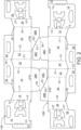
- Figure 2 illustrated a pair of like blanks 10A, 10B in a nested configuration.
- the first base panel 38A/38C comprises a first shaped free edge E1 substantially opposing a hinged edge defined by the hinged connection between the first base panel 38A/38C and the first side panel 18.
- the first free edge E1 is shown as a chamfered or filleted edge which is provided by a linear edge which may optionally extend from a side edge (e.g., the left end edge as viewed in Figure 1 ) of the second portion 38C toward, and optionally all the way to, the straight distal end edge (i.e. the lower end edge as viewed in Figure 1 ) of the first base panel 38A/38C.
- the first free edge E1 is linear along at least a portion thereof (the first chamfered edge E1 may be linear along at least a portion thereof) and the linear portion is obliquely oriented with respect to the fold line 37A and/or with respect the fold line 39.
- the first free edge E1 and the fold line 39 define an angle therebetween, which may be an acute angle and may be less than 45°, it may be about 30° or less.
- the first free edge E1 may extend from a side edge (e.g., the left end edge as viewed in Figure 1 ) of the first portion 38A of the first base panel 38A/38C toward, and optionally all the way to, the straight distal end edge (i.e., the lower end edge as viewed in Figure 1 ) of the first base panel 38A/38C.
- the second base panel 38B comprises a second shaped free edge E2 substantially opposing a hinged edge defined by the hinged connection between the second base panel 38B and the second side panel 24.
- the second free edge E2 is shown as a chamfered or filleted edge which is provided by a linear edge which may optionally extend from the fold line 37B toward, and optionally all the way to, the straight distal end edge E3 of the second base panel 38B.
- the second free edge E2 is linear along at least a portion thereof (the second chamfered edge E2 may be linear along at least a portion thereof) and the linear portion is obliquely oriented with respect to the third fold line 37B.
- the second free edge E2 and the fold line 37B define an angle therebetween, the angle may be an acute angle and may be less than 45°, it may be about 30° or less.
- the second free edge E2 if not the linear portion thereof, may intersect with the straight distal end edge E3 of the second base panel 38B at a point or corner which is equidistant from the fold lines 23 and 25 or which is closer to the fold line 25 than to the fold line 23.
- the second free edge E2 of the second blank 10B mates with, or tessellates with, the first free edge E1 of the first blank 10A.
- the first free edge E1 of the second blank 10B mates with, or tessellates with, the second free edge E2 of the first blank 10A.
- the first and second free edges E1, E2 of the first blank 10A share a common edge or cut with the second and first free edges E2, E1 of the second blank 10B, respectively.
- the first and second blanks 10A, 10B may also be arranged such that an end edge of the glue flap 12 of one of the first and second blanks 10A, 10B is colinear with an end edge of the second medial panel 28 of the other of the first and second blanks 10A, 10B.
- the end edges of the blanks 10A, 10B may be offset with respect to each other.
- the second free edge E2 is shaped complementarily to the first free edge E1.
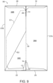
- the blank 10 is foldable to form a package 90 as illustrated in Figure 5 .
- the carton 90 can be formed by a series of sequential folding operations in a straight-line machine so that the carton 90 is not required to be rotated or inverted to complete its construction.
- the folding process is not limited to that described below and may be altered according to particular manufacturing requirements.
- Glue G or other adhesive treatment is applied to the first and second glue panels 72, 66 of the second partition structure P2 provided by the second medial panel 28.
- glue or other adhesive treatment may be applied to corresponding regions of the second side panel 24.
- Glue G or other adhesive treatment is applied to the second handle panel portion 28A.
- glue or other adhesive treatment may be applied to a corresponding region of the second handle reinforcing panel 34.
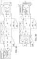
- the second medial panel 28 and the fourth end panel 26 are folded, with respect to the second side panel 24 about fold line 25, as shown in Figure 3B .
- the second medial panel 28 is brought into face contacting relationship with a portion of the second side panel 24 and the third end panel 22, the fourth end panel 26 is brought into face contacting relationship with a portion of the second side panel 24.
- the second handle panel portion 28A is brought into face contacting relationship with the second handle reinforcing panel 34.
- the first and second glue panels 72, 66 of the second partition structure P2 are secured to the second side panel 24 in face contacting relationship therewith.
- the second handle panel portion 28A is secured to the second handle reinforcing panel 34.
- Glue G or other adhesive treatment is applied to the first and second glue panels 72, 66 of the first partition structure P1 provided by the first medial panel 14. Alternatively, glue or other adhesive treatment may be applied to corresponding regions of the first side panel 18.
- Glue or other adhesive treatment is applied to the glue flap 12.
- glue or other adhesive treatment may be applied to a corresponding region of the third end panel 22.
- Glue G or other adhesive treatment is applied to the first handle panel portion 14A.
- glue or other adhesive treatment may be applied to a corresponding region of the first handle reinforcing panel 32.
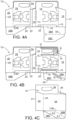
- the first medial panel 14, glue flap 12 and the first end panel 16 are folded, with respect to the first side panel 18 about fold line 17, as shown in Figure 4A .
- the first medial panel 14 is brought into face contacting relationship with a portion of the first side panel 18 and the second end panel 20.
- the first end panel 16 is brought into face contacting relationship with a portion of the first side panel 18.
- the glue flap 12 is brought into face contacting relationship with a portion of the third end panel 22.
- the first handle panel portion 14A is brought into face contacting relationship with the first handle reinforcing panel 32.
- the first handle panel portion 14A is secured to the first handle reinforcing panel 32.
- the first and second glue panels 72, 66 of the first partition structure P1 are secured to the first side panel 18 in face contacting relationship therewith.
- the glue flap 12 is secured to the third end panel 22 in face contacting relationship therewith.
- the first base panel 38A/38C is folded about fold line 39.
- the second portion 38C of first base panel 38A/38C is folded with respect to the first portion 38A of first base panel 38A/38C.
- the second portion 38C of first base panel 38A/38C is brought into face contacting relationship with the first portion 38A of first base panel 38A/38C.
- Glue or other adhesive treatment is applied to the second portion 38C of first base panel 38A/38C, as shown in Figure 4B .
- glue or other adhesive treatment may be applied to a corresponding region of the second base panel 38B.
- Glue or other adhesive treatment is applied to the first medial panel 14.
- glue or other adhesive treatment may be applied to corresponding regions of the second medial panel 28.
- the blank 10 is folded about fold line 21 to bring the first medial panel 14 into face contacting relationship with the second medial panel 28.
- the second base panel 38B is brought into face contacting relationship with the second portion 38C of first base panel 38A/38C.
- the second base panel 38B is secured to the second portion 38C of first base panel 38A/38C.
- a flat collapsed carrier is thereby formed, as shown in Figure 4C , the flat collapsed carrier can be readily shipped or distributed in the flat condition to a plant for erecting and loading with primary product containers.
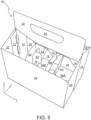
- the flat collapsed carrier can be opened into a basket-style article carrier 90, as shown in Figure 5 , by separating the first and second side panels 18, 24 to form a tubular structure defined by the outer panels 16, 18, 20, 22, 24, 26.
- the outer panels 16, 18, 20, 22, 24, 26 define an interior chamber.
- the partition structures P1, P2 are automatically erected when the flat collapsed carrier is opened out or erected into the tubular form.
- the first base panel 38A/38C and second base panel 38B form a composite base panel 38A/38C/38B which is automatically erected when the flat collapsed carrier is opened out.
- the first and second medial panels 14, 28 form a partition, that is disposed medially within the interior of the carrier 90 formed by the outer panels 16, 18, 20, 22, 24, 26.
- the partition divides the interior of the carrier 90 into two separate compartments on opposing sides of the first and second medial panels 14, 28.
- the partition extends longitudinally, as indicated by the direction arrow L in Figure 5 , of the carrier 90.
- the first partition structure P1 is automatically erected to form a first plurality of cells in a first compartment disposed on a first side of the first and second medial panels 14, 28.
- the second partition structure P2 is automatically erected to form a second plurality of cells in a second compartment disposed on a second side of the first and second medial panels 14, 28.
- the first and second partition structures P1, P2 extend transversely, as indicated by the direction arrow T in Figure 5 , of the carrier 90.
- the carrier 90 may be loaded with a group of articles; in the embodiment illustrated in Figure 5 six articles (not shown) are arranged in a 3 x 2 array.
- the group of articles may be loaded through an upper end of the tubular structure formed by the outer panels 16, 18, 20, 22, 24, 26.
- Figure 6 illustrates a second embodiment and shows a blank 110 having a plurality of panels 112, 114, 116, 118, 120, 122, 124, 126, 128 arranged in a linear series hinged one to the next by fold lines 113, 115, 117, 119, 121, 123, 125, 127 respectively.
- the blank 110 comprises a plurality of outer panels 116, 118, 120, 122, 124, 126for forming a tubular structure.
- the plurality of outer panels 116, 118, 120, 122, 124, 126 comprises a first end panel 116.
- a first side panel 118 is hingedly connected to the first end panel 116 by a hinged connection in the form of a fold line 117.
- a second end panel 120 is hingedly connected to the first side panel 118 by a hinged connection in the form of a fold line 119.
- a third end panel 122 is hingedly connected to the second end panel 120 by a hinged connection in the form of a fold line 121.
- a second side panel 124 is hingedly connected to the third end panel 122 by a hinged connection in the form of a fold line 123 and a fourth end panel 126 is hingedly connected to the second side panel 124 by a hinged connection in the form of a fold line 125.
- the blank 110 comprises a first base panel 138A/138C hinged to the first side panel 118 by a hinged connection in the form of a fold line 137A.
- the first base panel 138A/138C comprises a fold line 139 extending in a longitudinal direction across the first base panel 138A/138C so as to define first and second portions 138A, 138C respectively.
- the blank 110 comprises a second base panel 138B hinged to the second side panel 124 by a hinged connection in the form of a fold line 137B.
- the first and second base panels 138A/138C, 138B are also referred to herein as end closure flaps since they close an end of the tubular structure formed by the plurality of outer panels 116, 118, 120, 122, 124, 126.
- the first base panel 138A/138C comprises a first shaped free edge E1 substantially opposing a hinged edge defined by the hinged connection between the first base panel 138A/138C and the first side panel 118.
- the first free edge E1 is shown as a cut-away corner with an edge extending between the left end of the first panel 138A/138C and the lower end of the first panel while the second free edge E2 is shown as a shaped edge extending to define a serpentine-shaped left end of the second panel 138B.
- the first free edge E1 is a generally chamfered or filleted edge which includes a first edge portion along the first free edge E1.
- the first free edge E1 is linear along at least a first edge portion thereof.
- the first edge E1 may comprise at least two linear sections divergently arranged with respect to each other.
- the linear sections are obliquely oriented with respect to the first fold line 137A and/or with respect the second fold line 139.
- the first edge E1 comprises at least two sections divergently arranged with respect to each other.
- the first edge E1 may be defined by a combination of one or more linear sections and one or more curvilinear or arcuate sections.
- the first edge E1 may optionally extend from a side edge (e.g., the left end edge as viewed in Figure 6 ) of the second portion 138C toward, and optionally all the way to, the straight distal end edge (i.e. the lower end edge as viewed in Figure 6 ) of the first base panel 138A/138C.
- the first free edge E1 may extend from a side edge (e.g., the left end edge as viewed in Figure 6 ) of the first portion 138A of the first base panel 138A/138C toward, and optionally all the way to, the straight distal end edge (i.e., the lower end edge as viewed in Figure 6 ) of the first base panel 138A/138C.
- the outermost end or extremity of the first base panel 138A/138C may be linear in shape.
- the linear outermost end of the first base panel 138A/138C may be substantially parallel to the fold line 137A and/or the fold line 139.
- the second base panel 138B comprises a second shaped free edge E2 substantially opposing a hinged edge defined by the hinged connection between the second base panel 138B and the second side panel 124.
- the second free edge is a generally chamfered or filleted edge which includes linear edge portions.
- the second free edge E2 may comprise at least two linear sections divergently arranged with respect to each other.
- the linear sections are obliquely oriented with respect to the third fold line 137B.
- the second free edge E2 comprises at least two sections divergently arranged with respect to each other.
- the second free edge E2 may be defined by a combination of one or more linear sections and one or more curvilinear or arcuate sections.
- the second free edge E2 may optionally extend from the fold line 137B toward, and optionally all the way to, the straight distal end edge or outermost end E3 of the second base panel 138B.
- the second free edge E2 may include a first linear end section E2a and a second opposed linear end section E2b. Those linear end sections E2a, E2b are located at the opposite ends of the two intermediate linear sections in the embodiment of Figure 6 .
- the first linear end section E2a emanates from the fold line 137b while the second linear end section E2b intersects with the straight distal end edge E3 of the second base panel 138B.
- the intersection of the edges E2 and E3 may be located at a point which is equidistant from the fold lines 123 and 125 or which is closer to the fold line 125 than to the fold line 123.
- the outermost end or extremity (or distal end edge) E3 of the second base panel 138B may be linear in shape.
- the linear outermost end or distal end edge E3 of the second base panel 138B may be substantially parallel to the to the fold line 137B.
- the second free edge E2 is shaped complementarily to the first free edge E1.
- the second free edge E2 is configured to tessellate or nest with the first free edge E1.
- Figure 7 illustrates a third embodiment and shows a blank 210 having a plurality of panels 212, 214, 216, 218, 220, 222, 224, 226, 228 arranged in a linear series hinged one to the next by fold lines 213, 215, 217, 219, 221, 223, 225, 227 respectively.
- the blank 210 comprises a plurality of outer panels 216, 218, 220, 222, 224, 226 for forming a tubular structure.
- the plurality of outer panels 216, 218, 220, 222, 224, 226 comprises a first end panel 216.
- a first side panel 218 is hingedly connected to the first end panel 216 by a hinged connection in the form of a fold line 217.
- a second end panel 220 is hingedly connected to the first side panel 218 by a hinged connection in the form of a fold line 219.
- a third end panel 222 is hingedly connected to the second end panel 220 by a hinged connection in the form of a fold line 221.
- a second side panel 224 is hingedly connected to the third end panel 222 by a hinged connection in the form of a fold line 223 and a fourth end panel 226 is hingedly connected to the second side panel 224 by a hinged connection in the form of a fold line 225.
- the blank 210 comprises a first base panel 238A/238C hinged to the first side panel 218 by a hinged connection in the form of a fold line 237A.
- the first base panel 238A/238C comprises a fold line 239 extending in a longitudinal direction across the first base panel 238A/238C so as to define first and second portions 238A, 238C respectively.
- the blank 210 comprises a second base panel 238B hinged to the second side panel 224 by a hinged connection in the form of a fold line 237B.
- the first and second base panels 238A/238C, 238B are also referred to herein as end closure flaps since they close an end of the tubular structure formed by the plurality of outer panels 216, 218, 220, 222, 224, 226.
- the first base panel 238A/238C comprises a first shaped free edge E1 substantially opposing a hinged edge defined by the hinged connection between the first base panel 238A/238C and the first side panel 218.
- the first free edge E1 is a generally chamfered or filleted edge which may include a non-linear edge. In the embodiment illustrated in Figure 7 , the non-linear first free edge E1 is arcuate or curvilinear.
- the first free edge E1 is concave so as to bow inwardly; the first free edge E1 defines a recess in the distal portion 238C.
- the first edge E1 may optionally extend from a side edge (e.g., the left end edge as viewed in Figure 7 ) of the second portion 238C toward, and optionally all the way to, the straight distal end edge (i.e. the lower end edge as viewed in Figure 7 ) of the first base panel 238A/238C.
- the first free edge E1 may extend from a side edge (e.g., the left end edge as viewed in Figure 7 ) of the first portion 238A of the first base panel 238A/238C toward, and optionally all the way to, the straight distal end edge (i.e., the lower end edge as viewed in Figure 7 ) of the first base panel 238A/238C.
- the outermost end or extremity of the first base panel 238A/238C is linear along at least a portion thereof.
- the outermost or extremity of the first base panel 238A/238C may be linear in shape and may be substantially parallel to the fold line 237A and/or the fold line 239.
- the second base panel 238B comprises a second shaped free edge E2 substantially opposing a hinged edge defined by the hinged connection between the second base panel 238B and the second side panel 224.
- the second free edge E2 is a generally chamfered or filleted edge which may include a non-linear edge.
- the non-linear second free edge E2 is arcuate or curvilinear.
- the second free edge E2 is convex so as to bow outwardly; the second free edge E2 defines a bulged edge which bulges away from the fold line 239.
- the second free edge E2 may optionally extend from the fold line 237B toward, and optionally all the way to, the straight distal end edge or outermost end E3 of the second base panel 238B.
- the second free edge E2 may include a linear end section E2a.
- the linear end section E2a is located at the distal end of the arcuate section of the second free edge E2 in the embodiment of Figure 7 .
- the linear end section E2a emanates from the fold line 237B.
- the second free edge E2 intersects with the straight distal end edge E3 of the second base panel 238B.
- the intersection of the edges E2 and E3 may be located at a point or corner which is equidistant from the fold lines 223 and 225 or which is closer to the fold line 225 than to the fold line 223.
- the outermost end or extremity E3 of the second base panel 238B may be linear in shape.
- the outermost end the second base panel 238B may be substantially parallel to the to the fold line 237B.
- the second free edge E2 is shaped complementarily to the first edge E1.
- the second edge E2 is configured to tessellate or nest with the first edge E1.
- Figure 8 illustrates a fourth embodiment and shows a blank 310 having a plurality of panels 312, 314, 316, 318, 320, 322, 324, 326, 328 arranged in a linear series hinged one to the next by fold lines 333, 315, 317, 319, 321, 323, 325, 327 respectively.
- the blank 310 comprises a plurality of outer panels 316, 318, 320, 322, 324, 326 for forming a tubular structure.
- the plurality of outer panels 316, 318, 320, 322, 324, 326 comprises a first end panel 316.
- a first side panel 318 is hingedly connected to the first end panel 316 by a hinged connection in the form of a fold line 317.
- a second end panel 320 is hingedly connected to the first side panel 318 by a hinged connection in the form of a fold line 319.
- a third end panel 322 is hingedly connected to the second end panel 320 by a hinged connection in the form of a fold line 321.
- the first free edge E1 may optionally extend from a side edge (e.g., the left end edge as viewed in Figure 8 ) of the second portion 338C toward, and optionally all the way to, the straight distal end edge (i.e. the lower end edge as viewed in Figure 8 ) of the first base panel 338A/338C.
- the first free edge E1 may extend from a side edge (e.g., the left end edge as viewed in Figure 8 ) of the first portion 338A of the first base panel 338A/338C toward, and optionally all the way to, the straight distal end edge (i.e., the lower end edge as viewed in Figure 8 ) of the first base panel 338A/338C.
- first and second edges E1, E2 may adopt alternative shapes which have the effect of generally removing an outer corner portion of the first and second base panels 38A/38C, 38B; 138A/138C, 138B; 238A/238C, 238B; 338A, 338C, 338B.
- This allows the blanks 10; 110; 210; 310 to be nested in an efficient manner without substantial offset between ends of the nested blanks.
- the blank 410 comprises a first base panel 438A/438C hinged to the first side panel 418 by a hinged connection in the form of a fold line 437A.
- the first base panel 438A/438C comprises a fold line 439 extending across the first base panel 438A/438C so as to define first and second portions 438A, 438C respectively.
- the blank 410 comprises a second base panel 438B hinged to the second side panel 424 by a hinged connection in the form of a fold line 437B.
- the first and second base panels 438A/438C, 438B are also referred to herein as end closure flaps since they close an end of the tubular structure formed by the plurality of outer panels 416, 418, 420, 422, 424, 426.
- the first and second base panels 438A/438C, 438B are engageable with one another in an overlapping relationship to form a composite base wall 438A/438C/438B of a carrier 490(see Figure 20 ).
- the first base panel 438A/438C may comprise at least one opening AP for receiving a post or pinnacle Pt of a crate Ct (see Figures 19A, 19B ).
- the blank 410 may be constructed into a carrier and inserted into a crate Ct having at least one post, Figures 19A, 19B and 20 each show a portion of a crate Ct having a plurality of receiving locations Rt for articles B. In Figures 19A and 19B some of the article receiving locations Rt are occupied by an article B and some are vacant.
- an article carrier 490 is loaded into the crate Ct such that articles B in the carrier 490 are received in a respective article receiving location Rt.
- the crate Ct is adapted to receive a plurality of article carriers 490 each having a plurality of articles B therein.
- the illustrated embodiment is adapted to receive four article carriers 490 each of which accommodates six articles B.
- the first base panel 438A/438C comprises two openings AP, each for receiving a respective post or pinnacle Pt.
- the posts Pt are configured to be located in a void between a grouping of four articles, as shown in Figure 19B .
- Each opening AP is aligned with the void between said group of four articles B.
- Each of the openings AP in the first base panel 438A/438C interrupts the fold line 439 hinging the first portion 438A to the second portion 438C.
- the post openings AP may be square or diamond shaped.
- the second base panel 438B may comprise at least one cutaway in the form of a recess RP.
- the cutaway may take the form of an aperture.
- the at least one cutaway is arranged to be aligned with a respective one of the at least one post openings AP in the first base panel 438A/438C
- the blank 410 may comprise a medial structure including a first medial panel 414 and a second medial panel 428.
- Medial panels 414, 428 are also referred to herein as intermediate panels.
- the first medial panel 414 is hingedly connected at a first end of the plurality of outer panels 416, 418, 420, 422, 424, 426, to the first end panel 416, by a hinged connection in the form of a fold line 415.
- the second medial panel 428 is hingedly connected at a second, opposing, end of the plurality of outer panels 416, 418, 420, 422, 424, 426, to the fourth end panel 426, by a hinged connection in the form of a fold line 427.
- the first medial panel 414 provides a first handle panel portion 414A.
- the second medial panel 428 provides a second handle panel portion 428A. Together the first and second medial panels 414, 428 provide a two-ply handle structure, the second ply reinforcing the first ply.
- the first handle panel portion 414A comprises a first handle opening.
- the first handle opening may be defined at least in part by a first handle aperture A2 struck from an upper portion of the first medial panel 414.
- the second handle panel portion 428A comprises a second handle opening.
- the second handle opening may be defined at least in part by a second handle aperture A3 struck from, or defined within, an upper portion of the second medial panel 228.
- the second handle opening is arranged to be disposed in registry or alignment with the first handle opening in a setup condition.
- the blank 410 comprises a securing panel in the form of a medial partition glue flap 412 hingedly connected to an end of the first medial panel 414 (said end opposes an opposing end of the first medial panel 414 to which the first end panel 416 is hingedly connected, defined by fold line 415) by a hinged connection in the form of a fold line 413.
- the fold line 413 is continuous or uninterrupted.
- the blank 410 may comprise a partition structure P1, P2 which defines or creates a plurality of cells disposed on one or both sides of the divider formed by first and second medial panels 414, 428.
- the blank 410 comprises a first partition structure P1 that defines or creates a plurality of cells disposed between the first side panel 418 and the first medial panel 414.
- the first partition structure P1 is defined in a first partition panel portion 414B provided by a lower portion of the first medial panel 414.
- the blank 410 comprises a second partition structure P2.
- the second partition structure P2 defines or creates a plurality of cells disposed between the second side panel 424 and the second medial panel 428.
- the second partition structure P2 is defined in a second partition panel portion 428B provided by a lower portion of the second medial panel 428.
- the first compartment provides an interior for receiving at least a lower portion of one or more articles.
- the second compartment provides an interior for receiving at least a lower portion of one or more articles.
- the first and second partition structures P1, P2 are substantially similar in construction, albeit the second partition structure P2 is a mirror image (in blank form) of the first partition structure P1. In this way the first and second partition structures P1, P2 are disposed substantially in registry with each other when the blank 410 is folded into a flat collapsed form.
- the first and second partition structures P1, P2 will be described in further detail by reference to the first partition structure P1.
- the first partition structure P1 comprises a first partition panel 464 struck from, or defined in, the first medial panel 414 and hingedly connected, at a first or proximal end, thereto by a hinged connection in the form of a fold line 463.
- the first partition structure P1 comprises a second partition panel 468 struck from, or defined in, the first medial panel 414 and hingedly connected, at first or a proximal end, thereto by a hinged connection in the form of a fold line 469.
- the first and second partition panels 464, 468 are dimensioned to extend, laterally, between the first medial panel 414 and the first side panel 418 in a set up condition.
- the first partition structure P1 comprises a first glue panel 472 to which the first and second partition panels 464, 468 are coupled by a respective distal end joint. Each distal end joint is defined by a respective fold line 467, 475. Fold line 467 defines an outer end of the first partition panel 464, fold line 463 defines an inner end of the first partition panel 464 a linear dimension is defined therebetween.
- the first partition panel 464 is defined by a pair of first cutlines or severance line 473.
- the second partition panel 468 is defined by a second cutline or severance line 471.
- the second partition panel 468 comprises an outer end, defined by a portion of fold line 475.
- the second cutline 471 extends across fold line 415 and into the first end panel 416 to define a connecting portion between the second partition panel 468 and the first glue panel 472, the connecting portion may be considered to be part of the first glue panel 472.
- the connecting portion may be struck from, or defined in, the first end panel 416.
- Fold line 469 defines an inner end of the second partition panel 468.
- the second partition panel 468 is separated from the first glue panel 472 along or by a portion of an upper one of the first cutlines 473.
- Each end of the cutlines 473, 471 may extend beyond a respective fold line 463, 469 and may terminate with a "J' shaped cut.
- the blank 410 may comprise at least one post or pinnacle receiving structure.
- the at least one post or pinnacle receiving structure is defined in a panel 414, 428 providing a partition structure P1, P2; the post pinnacle receiving structure is spaced apart from the partition structure P1, P2 by a portion of said panel 414, 428.
- the at least one post or pinnacle receiving structure may comprise at least one article shield GD, GD2.
- the at least one article shield GD, GD2 may protect or cushion the articles B from a post or pinnacle Pt of the crate Ct and is configured to be disposed between said post Pt and the article B.
- the at least one article shield GD, GD2 comprises at least one guard or cushioning flap 480, 482, 484.
- the guard flaps 480, 482, 484 are struck from or defined in lower portions of the first or second medial panels 414, 428.
- a cushioning flap 480, 482, 484 provided by the second medial panel 428 is disposed in face-to-face relationship with, or aligned with, one of the cushioning flaps 480, 482 provided by the first medial panel 414.
- the first medial panel 414 comprises two pairs of opposing cushioning flaps 480, 482.
- the cushioning flaps 480, 482 of each pair are hinged in opposition to each other by respective fold lines 481, 483.
- the flaps 480, 482 of each pair of cushioning flaps 480, 482 are separated from each other by a cut line or severance line.
- Each flap 480, 482 of each pair of cushioning flaps 480, 482 comprises a lower free edge.
- the lower free edges of each pair of cushioning flaps 480, 482 may define a concave recess or inverted "V" shaped notch in a lower end of the first medial panel 414.
- the notch or recess may facilitate folding of the cushioning flaps 480, 482 out of the plane of the first medial panel 414.
- the second medial panel 428 comprises one pair of opposing cushioning flaps 480, 482.
- the cushioning flaps 480, 482 of are hinged in opposition to each other by respective fold lines 481, 483.
- the cushioning flaps 480, 482 are separated from each other by a cut line or severance line.
- the cushioning flaps 480, 482 comprise or define concave recess or inverted "V" shaped notch in a lower end of the second medial panel 428.
- the second medial panel 428 comprises a further cushioning flap 484 hinged thereto by a fold line 485 and struck from a marginal side portion of the second medial panel 428.
- the further cushioning flap 484 is configured to be disposed in face-to-face relationship with, or aligned with, one of the cushioning flaps 480, 482 provided by the first medial panel 414.
- the at least one pinnacle receiving structure may comprise at least one cutaway or recess R1, R2.
- the first medial panel 414 comprises first cutaway or recess R1 in a lower end edge thereof, the cushioning flaps 480, 482 are provided adjacent to the first recess R1, the free edges of the cushioning flaps 480, 482 define portions of the first recess R1.
- the cushioning flaps 480, 482 when folded out of the plane of the first medial panel 414 may be considered to define extensions of the first recess R1.
- the first recess R1 and the cushioning flaps 480, 482 are dimensioned so as to accommodate the posts Pt of the crate Ct.
- the second medial panel 428 comprises second recess R2 in a lower end edge thereof, the cushioning flaps 480, 482, 484 are provided adjacent to the second recess R2, the free edges of the cushioning flaps 480, 482, 484 define portions of the second recess R2.
- the cushioning flaps 480, 482, 484 when folded out of the plane of the first medial panel 414 may be considered to define extensions of the second recess R2.
- the second recess R2 and the cushioning flaps 480, 482, 484 are dimensioned so as to accommodate the posts Pt of the crate Ct.
- the cushioning flaps 480, 482, 484 substantially surround the post Pt, the posts Pt may comprise a substantially diamond shaped cross section, alternative shapes may be employed such as square or four-pointed star shape.
- a cushioning flap 480, 482, 484 may be folded out of the panel of the medial panel 414, 428 to which it is hinged when the post Pt is received in the article carrier 490.
- a cushioning flap 480, 482, 484 may be folded about each of the four side walls of the post Pt.
- a pair of cushioning flaps 480, 482, 484 may be folded about one of the side walls of the post Pt. That is to say two cushioning flaps 480, 482, 484 may be disposed between the post Pt and one of the articles B received in the article carrier 490.
- the second medial panel 428 does not extend fully between the opposing ends of the carrier 490, only three cushion flaps 480, 482, 484 are provided by the second medial panel 428, one of the posts Pt received in the carrier 490 is engaged by three cushioning flaps 480, 482, 484 whereas the other of the posts Pt received in the carrier is engaged by four cushioning flaps 480, 482.
- the blank 410 may comprise a securing device for engaging the divider or intermediate wall 414/428 of the carrier 490 with the base wall 438A/438B/438C.
- the first medial panel 414 comprises a first hook H1 defined in a lower region of the first medial panel 414 and disposed adjacent to the first recess R1.
- the first hook H1 can be considered to extend into the first recess R1.
- the first hook H1 may be defined by an undercut integral with the first cutaway or recess R1. Both the first hook H1 and the first cutaway or recess R1 are defined within the first medial panel 414.
- the second medial panel 428 comprises a second hook H2 defined in a lower region of the second medial panel 428 and disposed adjacent to the second recess R2.
- the second hook H2 can be considered to extend into the second recess R2.
- the second hook H2 may be defined by an undercut integral with the second cutaway or recess R2. Both the second hook H2 and the second cutaway or recess R2 are defined within the second medial panel 428.
- the first and second hooks H1, H2 may be configured to be in face-to-face relationship with each other when the blank 410 is erected into a carrier 490, in this way the securing device is a two-ply structure.
- the first and second hooks H1, H2 may be configured to be disposed in opposition to each other in the erected carrier so as to engage opposing edges of the base wall.
- the fold lines 421, 413 together define a working crease in the carrier 490, the carrier 490 may be readily erected from, or flattened into, a flat tubular collapsed tubular structure; the first and second hooks H1, H2 may be disposed opposite said working crease of the carrier 490.
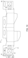
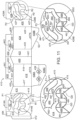
- FIG. 12 there is shown a plan view of a blank 510 according to a seventh embodiment.
- the blank 510 is substantially similar in construction to the blank of Figure 11 , albeit employing the partition structures P1, P2 of the embodiment of Figure 1 .
- the fold line 513 hinging glue flap 512 to first medial panel 514 is interrupted by a pair of apertures A1, similar to the blank 10 of Figure 1 .
- the first medial 514 comprises a first post or pinnacle receiving recess R1 in a lower edge thereof, that is to say an edge facing or adjacent to the base wall 538A/538B/538C of the carrier 590 shown in Figure 21
- Second medial 528 comprises a second post or pinnacle receiving recess R2 in a lower edge thereof, that is to say an edge facing or adjacent to the base wall 538A/538B/538C of the carrier 590 shown in Figure 21 .
- the second pinnacle receiving recess R2 is configured to be in registry with at least a portion of the first pinnacle receiving recess R1; the second pinnacle receiving recess R2 corresponds to or with a portion of the first pinnacle receiving recess R1.
- the blank 510 may comprise a securing device for engaging the divider or intermediate wall 514/528 of the carrier 590 with the base wall 538A/538B/538C.
- the first medial panel 514 comprises a pair of first hooks H1 defined in a lower region of the first medial panel 514 and disposed adjacent to the first recess R1.
- the first hooks H1 can be considered to extend into the first recess R1.
- the first hooks H1 may be defined by undercuts integral with the first cutaway or recess R1. Both the first hooks H1 and the first cutaway or recess R1 are defined within the first medial panel 514.
- the first hooks H1 of the pair of first hooks H1 are disposed in opposition to each other, and are configured to engage opposing end edges of base wall 538A/538B/538C of the carrier 590.
- the second medial panel 528 comprises a second hook H2 defined in a lower region of the second medial panel 528 and disposed adjacent to the second recess R2.
- the second hook H2 can be considered to extend into the second recess R2.
- the second hook H2 may be defined by an undercut integral with the second cutaway or recess R2. Both the second hook H2 and the second cutaway or recess R2 are defined within the second medial panel 528.
- the second hook H2 is arranged to be disposed in registry with one of the pair of first hooks H1 to form a to ply hook H1/H2.
- the two-ply hook H1/H2 may comprise in creased strength or rigidity over a single ply hook H1.
- the two-ply hook H1/H2 may be arranged to be in opposition to a working crease of the carrier 590 defined by fold lines 513/521.
- Figure 20 illustrates an internal view of a carrier 590 formed form the blank 510, the carrier 590 has been inserted into a crate Ct, articles B have been removed from the carrier 590 for illustrative purposes.
- the intermediate wall 514/528 provides first and second partition structures P1, P2 and a receiving structure R1/R2 to accommodate the posts Pt, the receiving structure R1/R2 is spaced a part from the partition structures P1, P2 by a portion of intermediate wall 514/528.
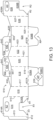
- FIG. 13 there is shown a plan view of a blank 610 according to an eighth embodiment.
- the blank 610 is adapted to accommodate a group of four articles arranged in a 2 x 2 matrix or array.
- the partition structures P1, P2 of previous embodiments have been omitted.
- the first and second medial panels 614, 628 each comprise a respective post or pinnacle receiving recess R1, R2 in a lower edge thereof, that is to say an edge facing or adjacent to the base panels 638A, 638B, 638C in a setup condition.
- the blank 610 comprises a securing device for engaging the divider or intermediate wall 614/628 of a carrier formed from the blank 610 with the base wall 638A/638B/638C.
- the first medial panel 614 comprises a pair of first hooks H1 defined in a lower region of the first medial panel 614 and disposed adjacent to a first recess R1.
- the first hooks H1 can be considered to extend into the first recess R1.
- the first hooks H1 may be defined by an undercut integral with the first cutaway or recess R1.
- the first hooks H1 and the first cutaway or recess R1 are defined entirely within the first medial panel 614.
- the second medial panel 628 comprises a second hook H2 defined in a lower region of the second medial panel 628 and disposed adjacent to a second recess R2.
- the second hook H2 can be considered to extend into the second recess R2.
- the second hook H2 may be defined by an undercut integral with the second cutaway or recess R2. Both the second hook H2 and the second cutaway or recess R2 are defined within the second medial panel 628.
- the first and second hooks H1, H2 may be configured to be in face-to-face relationship with each other when the blank 610 is erected into a carrier, in this way the securing device is a two-ply structure.
- the first and second hooks H1, H2 may be configured to be disposed in opposition to each other in the erected carrier so as to engage opposing edges of the base wall 638A/638B/638C.
- the fold lines 621, 613 together define a working crease in the carrier, the carrier may be readily erected from, or flattened into, a flat tubular collapsed tubular structure; the first and second hooks H1, H2 may be disposed opposite said working crease of the carrier.
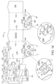
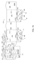
- FIG. 14 there is shown a plan view of a blank 710 according to a ninth embodiment.
- the blank 710 is adapted to accommodate a group of six articles arranged in a 2 x 3 matrix or array.
- the embodiment of Figure 14 comprises unitary end wall panel 720/722, 726, that is to say the fold lines 21, 421, 521, for example, employed in previous embodiments have been omitted.
- the fourth end panel 726 is dimensioned to extend fully between first and second side wall panels 718, 724.
- First end wall panel 716 is arranged to be disposed in face contacting relationship with a portion of the fourth end panel 726.
- a second medial panel 728 is hingedly connected to a lower edge of the first medial panel 714 by a hinged connection in the form of a fold line 729.
- the hinged connection or fold line 729 is offset with respect to lower edges of the side and end panels 716, 718, 720/722, 724, 726.
- the second medial panel 728 is configured to be folded into face-to-face relationship with the first medial panel 714, as indicated in Figure 14B by direction arrow D1.
- the second medial panel 728 is folded about fold line 729, in doing so a recess R is created in a lower edge of the intermediate panel 714/728 formed by the first and second medial panel 714, 728.
- first and second medial panel 714, 728 are interrupted by at least one cutaway in the form of an aperture AP.
- the illustrated embodiment comprises a pair of apertures AP.
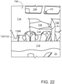
- the apertures AP form extensions RP of the recess R, these recess extensions RP are arranged to accommodate a post or pinnacle Pt of a crate Ct, as shown in Figure 22 .
- a portion of the glue panel of the second partition structure P2 may be struck from material which would otherwise form the medial partition glue flap 713.
- the first base panel 738A comprises at least one first opening configured to receive a post or pinnacle Pt of a crate Ct.
- the illustrated embodiment comprises a plurality of first post receiving openings, specifically, but not limited to, two first openings.
- the second base panel 738B comprises at least one second opening configured to receive a post or pinnacle Pt of a crate Ct.
- the second opening is arranged to be in registry with the first opening.
- the illustrated embodiment comprises a plurality of second post receiving openings, specifically, but not limited to, two second openings.
- Each of the first openings is defined, at least in part, by a pair of female tabs FT1, FT2 each hingedly connected to the first base panel 738A by a respective fold line F1, F2. Cutaways in the form of apertures define notches N1, N2 in lower or proximal regions -the lower or proximal region being disposed adjacent to the hinged connection or fold line F1, F2- of the female tabs FT1, FT2.
- the female tabs FT1, FT2 may be substantially "T" shaped.
- Each of the second openings is defined, at least in part, by a pair of male tabs MT1, MT2 each hingedly connected to the second base panel 738B by a respective fold line F3, F4. Cutaways in the form of apertures define notches N3, N3 in upper or distal regions -the upper or distal region being disposed adjacent to a free end of the male tabs MT1, MT2, the free end opposes a hinged end defined by the hinged connection or fold line F1, F2- of the female tabs FT1, FT2.
- the notches N1, N2 of the female tabs FT1, FT2 receive lug or lobes of the male tabs MT1, MT2 to secure the male and female tabs MT1, MT2, FT1, FT2 in a folded condition.
- the male and female tabs MT1, MT2, FT1, FT2 form part of a complementary locking mechanism for locking the first and second base panel 738A, 738B in an overlapping relationship with each other.
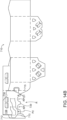
- the first base panel 738A comprises at least one handling or machine aperture AM, the first base panel 738A comprises a plurality of machine apertures AM, specifically, but not limited to, three machine apertures AM.
- the machine apertures AM are disposed adjacent or proximate to the hinged connection between first base panel 738A and the first side panel 718.
- the second base panel 738B comprises at least one handling or machine aperture AM, the second base panel 738B comprises a plurality of machine apertures AM, specifically, but not limited to, three machine apertures AM.
- the machine apertures AM are disposed adjacent or proximate to the hinged connection between second base panel 738B and the second side panel 724.
- the machine apertures AM comprise an opening at least a portion of which is substantially triangular in shape.
- the first base panel 738A comprises cutaway in the form of an aperture AD configured to be disposed in registry with one of the plurality of machine apertures AM in the second base panel 738B.
- the second base panel 738B comprises cutaway in the form of a recess RM configured to be disposed in registry with a portion of one of the plurality of machine apertures AM in the first base panel 738A.
- the first and second base panels 738A, 738B form a foldable end or base closure.
- the first base panel 738A is hinged to a tubular structure formed from the main panels 716, 718, 720/722, 724, 726 along a first fold line 737A.
- the second base panel 738A is hinged to the tubular structure formed from the main panels 716, 718, 720/722, 724, 726 along a second fold line 737B.
- the first base panel 738A comprises a first free edge EE1 opposing a hinged edge defined by the first fold line 737A.
- the second base panel 738B comprises a second free edge EE2 opposing a hinged edge defined by the second fold line 737B.
- the first base panel 738A comprises at least one first panel-interlocking element F and a row of first handling openings AM.
- the first handling openings AM are located closer to the first fold line 737A than the at least one first panel-interlocking element F.
- the second base panel 738B comprises at least one second panel-interlocking element M.
- the second base panel 738B comprises a row of second handling openings AM.
- the second handling openings AM are located closer to the second fold line 737B than the at least one second panel-interlocking element M.
- the first and second panel-interlocking elements F, M are aligned and engaged together such that the first and second base panels 737A, 737B are in face-contacting overlapping arrangement.
- the first base panel 737A has a first side edge SE1 extending between the first fold line 737A and the first free edge EE1.
- the second base panel 738B has a second side edge SE2 extending between the second fold line 737B and the second free edge EE2.
- At least a part SE1a of the first side edge SE1 is configured complementary to at least a part SE2a of the second free edge SE2.
- At least a part SE2b of the second side edge SE2 is disposed between the at least one first panel-interlocking element F and one of the first handling openings AM such that no part of the second side edge SE2 overlaps any one of the at least one first panel-interlocking element F and the first handling openings AM.
- At least part of the second free edge EE2 is disposed between the first fold line 737A and a first notional line X1-X1.
- First notional line X1-X1 is defined by a linear line in tangential contact with a forward or leading edge of each of the first handling openings AM.
- First notional line X1-X1 extends parallel to the first fold line 737A.
- Second notional line X2-X2 is defined by a linear line in tangential contact with a forward or leading edge of each of the second handling openings AM. Second notional line X2-X2 extends parallel to the second fold line 737B.
- At least a part SE1b of the first side edge SE1 is disposed between the at least one second panel-interlocking element M and one of second handling openings AM such that no part of the first side edge SE1 overlaps any one of the at least one second panel-interlocking element M and the second handling openings AM.
- FIG. 15 there is shown a plan view of a blank 810 according to a tenth embodiment.
- the embodiment of Figure 15 can be erected to form a carrier 890 as shown in Figure 18 .
- the blank 810 is substantially similar in construction to the blank 710 of Figure 14 , albeit the first base panel 838A and second base panel 838B have a different shape.
- the first base panel 838A has been shortened a recess RM replaces the aperture AD of the ninth embodiment.
- the recess RM serves the same purpose as the aperture AD providing access through the first base panel 838A for a machine tool (not shown) to enable the first and second base panel 838A, 838B to be aligned with respect to each other such that the panel locking arrangement M/F can be deployed to secure the first and second base panel 838A, 838B to each other.
- FIG. 16 there is shown a plan view of a blank 910 according to an eleventh embodiment.
- the blank 910 forms a carrier (not shown) having a plurality of main panels 916, 918, 920, 922, 924, 926 forming a tubular structure.
- the tubular structure is closed at one end by an end closure or base wall formed from a first base panel 938A/938C and a second base panel 938B.
- An intermediate wall 914/928 is provided by a pair of medial panels 914, 928.
- the intermediate wall 914/928 provides a pair of partition structures for dividing chamber on each side of the intermediate wall 914/928 into a plurality of cells.
- the blank 910 is arranged substantially as two rows or series of panels, previous embodiments were arranged substantially as single linear series.
- a first row of panels comprises a first riser panel 912 is hingedly connected to a first end panel 916 by a hinged connection in the form of a fold line 913.
- a first side panel 918 is hingedly connected to the first end panel 916 by a hinged connection in the form of a fold line 917.
- a second end panel 920 is hingedly connected to the first side panel 918 by a hinged connection in the form of a fold line 919.
- a first medial panel 914 is hingedly connected to the second end panel 920 by a hinged connection in the form of a fold line 927A.
- a second row of panels comprises a second riser panel 930 is hingedly connected to a third end panel 922 by a hinged connection in the form of a fold line 921.
- a second side panel 924 is hingedly connected to the third end panel 922 by a hinged connection in the form of a fold line 923.
- a fourth end panel 926 is hingedly connected to the second side panel 924 by a hinged connection in the form of a fold line 925.
- a second medial panel 928 is hingedly connected to the fourth end panel 922 by a hinged connection in the form of a fold line 9927B.
- the first row of panels is hingedly connected to the second row of panels; the first riser panel 912 is hingedly connected to the second riser panel 930 by a hinged connection in the form of a fold line 915A.
- the first medial panel 914 is hingedly connected to the second medial panel 928 by a hinged connection in the form of a fold line 915B.
- Fold line 915B be may be interrupted by one or more apertures to reduce its resistance to folding.
- a pair of handle reinforcing panels 932, 934 is provided between the first and second side panels 918, 924.
- a first handle reinforcing panel 932 is hingedly connected to the first medial panel 914 by a hinged connection in the form of a fold line.
- a second handle reinforcing panel 934 is hingedly connected to the second medial panel 928 by a hinged connection in the form of a fold line.
- the first handle reinforcing panel 932 is hingedly connected to the second handle reinforcing panel 934 by a hinged connection in the form of a fold line 915C.
- Fold line 915C is collinear with fold line 915A and fold line 915B.
- the blank 910 comprises a first base panel 938A/938C hinged to the first side panel 918 by a hinged connection in the form of a fold line 937A.
- the first base panel 938A/938C comprises a fold line 939 extending in a longitudinal direction across the first base panel 938A/938C so as to define first and second portions 938A, 938C respectively.
- the first and second portions 938A, 938C are also referred to herein as proximal and distal portions respectively.
- the blank 910 comprises a second base panel 938B hinged to the second side panel 924 by a hinged connection in the form of a fold line 937B.
- the first and second base panels 938A/938C, 938B are also referred to herein as end closure flaps since they close an end of the tubular structure formed by the plurality of outer panels 916, 918, 920, 922, 924, 926.
- the first and second base panels 938A/938C, 938B are engageable with one another in an overlapping relationship to form a composite base wall 938A/938C/938B of the carrier.
- the first base panel 938A/938C may comprise at least one cutaway struck from an end edge.
- the cutaway is engageable with a hook or catch H1, H2 provided by at least one of the panels 914, 928.
- the blank 910 comprises a first and second partition structure P1, P2.
- the first partition structure P1 defines or creates a plurality of cells disposed between the first side panel 918 and the first medial panel 914.
- the first partition structure P1 is defined in a first partition panel portion provided by a lower portion of the first medial panel 914.
- the blank 910 comprises a second partition structure P2.
- the second partition structure P2 defines or creates a plurality of cells disposed between the second side panel 924 and the second medial panel 428.
- the second partition structure P2 is defined in a second partition panel portion provided by a lower portion of the second medial panel 428.
- the first and second partition structures P1, P2 are substantially similar in construction, albeit the second partition structure P2 is a mirror image (in blank form) of the first partition structure P1. In this way the first and second partition structures P1, P2 are disposed substantially in registry with each other when the blank 910 is folded into a flat collapsed form.
- the first and second partition structures P1, P2 will be described in further detail by reference to the first partition structure P1.
- the first partition structure P1 comprises a first partition panel 964 struck from, or defined in, the first medial panel 914 and hingedly connected, at a first or proximal end, thereto by a hinged connection in the form of a fold line.
- the first partition structure P1 comprises a second partition panel 968 struck from, or defined in, the first medial panel 914 and hingedly connected, at first or a proximal end, thereto by a hinged connection in the form of a fold line.
- the first and second partition panels 964, 968 are dimensioned to extend, laterally, between the first medial panel 914 and the first side panel 918 in a set up condition.
- the first partition structure P1 comprises a first glue panel 972 to which the first and second partition panels 964, 968 are coupled by a respective distal end joint. Each distal end joint is defined by a respective fold line.
- the blank 910 may comprise at least one post or pinnacle receiving structure.
- the at least one post or pinnacle receiving structure is defined in a panel 914, 928 providing a partition structure P1, P2; the post pinnacle receiving structure is disposed adjacent to the respective partition structure P1, P2 in said panel 914, 928.
- the at least one post or pinnacle receiving structure may comprise at least one article guard shield GD, GD2.
- the at least one article shield GD may protect or cushion the articles B from a post or pinnacle Pt of the crate Ct and is configured to be disposed between said post Pt and the article B.
- the at least one article shield GD comprises at least one guard flap 980, 982.
- the guard flaps 980, 982 are struck from or defined in lower portions of one of the first and second medial panels 914, 928.
- a cushioning flap 980, 982 provided by the second medial panel 928 is disposed in face-to-face relationship with, or aligned with, one of the cushioning flaps 980, 982 provided by the first medial panel 914.
- the first medial panel 914 comprises a pair of opposing cushioning flaps 980, 982.
- the cushioning flaps 980, 982 are hinged in opposition to each other by respective fold lines 981, 983.
- the flaps 980, 982 of each pair of cushioning flaps 980, 982 are separated from each other by a cut line or severance line.
- Each flap 980, 982 of each pair of cushioning flaps 980, 982 comprises a lower free edge.
- the lower free edges of each pair of cushioning flaps 980, 982 may define a concave recess or inverted "V" shaped notch in a lower end of the first medial panel 914.
- the notch or recess may facilitate folding of the cushioning flaps 980, 982 out of the plane of the first medial panel 914.
- the first medial panel 914 comprises a first cutaway or recess R1 in a lower end edge thereof, the cushioning flaps 980, 982 are provided adjacent to the first recess R1, the free edges of the cushioning flaps 980, 982 define portions of the first recess R1.
- the cushioning flaps 980, 982 when folded out of the plane of the first medial panel 914 may be considered to define extensions of the first recess R1.
- the first recess R1 and the cushioning flaps 980, 982 are dimensioned so as to accommodate the posts Pt of the crate Ct.
- the second medial panel 928 comprises a second cutaway or recess R2 in a lower end edge thereof, the second cutaway or recess R2 is arranged similarly to the first cutaway or recess R1 in the first medial panel 914 and will not be described in further detail.
- the blank 910 may comprise a securing device for engaging the divider or intermediate wall 914/928 of the carrier with the base wall 938A/938B/938C.
- the second medial panel 928 comprises a second hook H2 defined in a lower region of the second medial panel 928 and disposed adjacent to the second recess R2.
- the second hook H2 can be considered to extend into the second recess R2.
- the second hook H2 may be defined by an undercut integral with the second cutaway or recess R2. Both the second hook H2 and the second cutaway or recess R2 are defined within the second medial panel 928.
- the first and second hooks H1, H2 may be configured to be in face-to-face relationship with each other when the blank 910 is erected into a carrier, in this way the securing device is a two-ply structure.
- the first and second hooks H1, H2 may be configured to be disposed in opposition to each other in the erected carrier so as to engage opposing edges of the base wall.
- the first and second opposed end walls 16/26, 20/22; 116/126, 120/122; 216/226, 220/222; 316/326, 320/322 each comprise a hinge to facilitate folding of the collapsible tubular structure 90 between a stowed condition and an erected condition.
- the collapsible article carrier 90 comprises a medial partition wall 14/28; 114/128; 214/228; 314/328 interposed parallel between first and second side panels 18, 24; 118, 124; 218, 224; 318, 324 to divide the interior into two or more article-receiving cells.
- the present disclosure provides a blank 10; 110; 210; 310; 410; 510; 710; 810 for forming an article carrier 90; 490; 590; 790; 890.
- the blank 10; 110; 210; 310; 410; 510; 710; 810 comprises a plurality of primary panels 16, 18, 20, 22, 24, 26; 116, 118, 120, 122, 124, 126; 216, 218, 220, 222, 224, 226; 316, 318, 320, 322, 324, 326; 416, 418, 420, 422, 424, 426; 516, 518, 520, 522, 524, 526; 716, 718, 720, 722, 724, 726; 816, 818, 820, 822, 824, 826; for forming walls of a tubular structure defining an interior chamber.
- the first panel 38A/38C; 138A/138C; 238A/238C; 338A, 338C; 438A/438C; 538A/538C; 738A; 838A comprises a proximal portion 38A; 138A; 238A; 338A and a distal portion 38C; 138C; 238C; 338C; 438C; 538C.
- the proximal portion 38A; 138A; 238A; 338A is hinged, along a first fold line 37A; 137A; 237A; 337A, 437A, 537A to one of the panels forming a wall of the tubular structure.
- the distal portion 38C; 138C; 238C; 338C; 438C; 538C may be hinged to the proximal portion along a second fold line 39; 139; 239; 339; 439; 539.
- the second panel 38B; 138B: 238B; 338B is hinged, along third fold line 37B; 137B; 237B; 337B, to a second one of the panels forming an opposing wall of the tubular structure.
- the second panel 38B; 138B: 238B; 338B; 438B; 538A; 738B; 838B is configured to be securable the first panel 38A/38C; 138A/138C; 238A/238C; 338A, 338C; 438A/438C; 538A/538C; 738A; 838A (optionally to the distal portion 38C; 138C; 238C; 338C; 438C; 538C) in face-contacting arrangement and in at least partial overlapping relationship therewith.
- the first 37A; 137A; 237A; 337A; 437A; 537A and third 37B; 137B; 237B; 337B; 437B; 537B fold lines are parallel to one another.
- the second fold line 39; 139; 239; 339, 439; 539 may be parallel to the first 37A; 137A; 237A; 337A; 437A; 537A and third 37B; 137B; 237B; 337B; 437B; 537B fold lines.
- the second free edge E2 is arranged to extend alongside the first free edge E1 in set up carrier 90 when in both an erected condition and a stowed condition.
- the first panel 38A/38C; 138A/138C; 238A/238C; 338A, 338C; 438A/438C; 538A/538C; 738A; 838A may comprise at least one post receiving opening AP or recess RM.
- the second panel 38B; 138B: 238B; 338B; 438B; 538A; 738B; 838B may comprise at least one post receiving opening AP or recess RM.
- the at least one post receiving opening AP may interrupt the second fold line 39; 139; 239; 339; 439; 539.
- the present disclosure provides an article carrier 790; 890 and a blank 710; 810 for forming the same; wherein the article carrier 790; 890 comprises a collapsible tubular structure and an end closure.
- the end closure comprises a first panel 738A; 838A and a second panel 738B; 838B.
- the first panel 738A; 838A is hinged to the tubular structure along a first fold line 737A; 837A and comprises an opposing first free edge EE1.
- the first panel 738A; 838A comprises at least one first panel-interlocking element F and a row of first handling openings AM.
- the row of first handling openings AM is located closer to the first fold line 737A; 837A than the at least one first panel-interlocking element F.
- the second panel 738B; 838B is hinged to the tubular structure along second fold line 737B; 837B and comprises an opposing second free edge EE2.
- the second panel 738B; 838B comprises at least one second panel-interlocking element M.
- the first and second panel-interlocking elements F, M are aligned and engaged together such that the first and second panels 738A, 738B; 838A, 838B are in face-contacting overlapping arrangement.
- the first panel 738A; 838A has a first side edge SE1 extending between the first fold line 737A; 837A and the first free edge EE1.
- the second panel 738B; 838B has a second side edge SE2 extending between the second fold line 737B; 837B and the second free edge EE2.
- At least a part SE1a of the first side edge SE1 is configured complementary to at least a part SE2a of the second free edge SE2 (see Figure 14C ).
- At least a part SE2b of the second side edge SE2 is disposed between the at least one first panel-interlocking element F and one of the first handling openings AM such that no part of the second side edge SE2 overlaps any one of the at least one first panel-interlocking element F and the first handling openings AM.
- At least part of the second free edge SE2 is disposed between the first fold line 737A; 837A and a first notional line X1-X1.
- At least part of the first free edge EE1 is disposed between second fold line 737B; 837B and a second notional line X2-X2.
- the second panel 738B; 838B comprises a row of second handling openings AM.
- the row of second handling openings AM is located closer to the second fold line 737B; 837B than the at least one second panel-interlocking element M.
- At least a part SE1b of the first side edge SE1 is disposed between the at least one second panel-interlocking element M and one of second handling openings AM such that no part of the first side edge SE1 overlaps any one of the at least one second panel-interlocking element M and the second handling openings AM.
- the present disclosure also provides an article carrier 490 and a blank 410; 910 for forming the same; wherein the article carrier 490 comprises a plurality of primary panels 416, 418, 420, 422, 424, 426; 916, 918, 920, 922, 924, 926 forming a tubular structure defining an interior of the article carrier 490.
- the carrier 490 may comprise an intermediate wall 414/428; 914/928 dividing the interior into two chambers.
- the intermediate wall 414/428; 914/928 comprises an article guard GD comprising at least one flap 480, 482, 484; 980, 982 configured to be disposed between an article B and a post Pt of a tertiary package or crate Ct receivable in the carrier 490.
- the at least one flap 480, 482, 484; 980, 982 defines at least in part an opening in the intermediate wall 414/428; 914/928 for receiving said crate post Pt.
- the present disclosure also provides an article carrier 490; 590 for packaging articles B and a blank 410; 510; 610; 910 for forming the same.
- the article carrier 490; 590 comprises a plurality of primary panels 416, 418, 420, 422, 424, 426; 516, 518, 520, 522, 524, 526; 616, 618, 620, 622, 624, 626; 916, 918, 920, 922, 924, 926 forming a tubular structure defining an interior of the article carrier 490; 590.
- the carrier 490; 590 comprises an end wall 438A/438B/438C; 538A/538B/538C; 638A/638B/638C; 938A/938B/938C closing an end of the tubular structure.
- the carrier 490; 590 may comprise an intermediate wall 414/428; 514/528; 614/628; 914/928 dividing the interior into a pair of chambers.
- the intermediate wall 414/428; 514/528; 614/628; 914/928 comprises a post receiving opening and a securing device for retaining the carrier 490; 590 in an erected condition.
- the post receiving opening is arranged to accommodate at least one post Pt of a tertiary package or crate Ct receivable in the carrier 490; 590 through the end wall 438A/438B/438C; 538A/538B/538C; 638A/638B/638C; 938A/938B/938C.
- the securing device comprises a hook or catch defined at least in part by a portion of post receiving opening.
- the securing device and the post receiving opening being defined in entirety within the intermediate wall 414/428; 514/528; 614/628; 914/928 or a panel 414, 428; 514, 528; 614, 628; 914, 928 forming the intermediate wall 414/428; 514/528; 614/628; 914/928.
- the present disclosure also provides an article carrier 490; 590 and a blank 410; 510; 610; 910 for forming the same; wherein the article carrier 490; 590 comprises a plurality of primary panels 416, 418, 420, 422, 424, 426; 516, 518, 520, 522, 524, 526; 616, 618, 620, 622, 624, 626; 916, 918, 920, 922, 924, 926 forming a tubular structure defining an interior of the article carrier 490; 590.
- the carrier 490; 590 may comprise an intermediate wall 414/428; 514/528; 614/628; 914/928 dividing the interior into a pair of chambers.
- the intermediate wall 414/428; 514/528; 614/628; 914/928 comprises a post receiving opening and at least one partition structure P1, P2.
- the at least one partition structure P1, P2 separates one of the pair of chambers into two or more article-receiving cells.
- the post receiving opening is arranged to accommodate at least one post Pt of a tertiary package or crate Ct receivable in the carrier 490; 590.
- the post receiving opening is disposed between the at least one partition structure P1, P2 and an end wall 438A/438B/438C; 538A/538B/538C; 638A/638B/638C; 938A/938B/938C closing an end of the tubular structure and is spaced apart from the at least one partition structure P1, P2 by a portion of the intermediate wall 414/428; 514/528; 614/628; 914/928.
- the end wall 438A/438B/438C; 538A/538B/538C; 638A/638B/638C; 938A/938B/938C comprises an opening for receiving said at least one crate post Pt.
- the article carrier 490; 590 forms a packaging system with a plurality of articles B and a tertiary package Ct.
- the articles B are disposed in the interior of the carrier 490; 590 and the carrier 490; 590 is disposed in the tertiary package Ct.
- the crate post Pt is received in the interior of the carrier 490; 590 and is disposed in a void defined at least in part by two or more articles B.
- the portion of the intermediate wall 414/428; 514/528; 614/628; 914/928 between the at least one partition structure P1, P2 and the post receiving opening is disposed over said at least one crate post Pt.
- the present disclosure also provides an article carrier 790; 890 and a blank 710; 810 for forming the same; wherein the article carrier 790; 890 comprises a plurality of primary panels 716, 718, 720, 722, 724, 726; 816, 818, 820, 822, 824, 826 forming a tubular structure defining an interior of the article carrier 790; 890.
- the carrier 790; 890 comprises an end wall 737A/737B; 837A/837B closing an end of the tubular structure.
- the carrier 790; 890 comprise an intermediate wall 414/428; 514/528; 614/628; 914/928 dividing the interior into a pair of chambers.
- the intermediate wall 414/428; 514/528; 614/628; 914/928 comprises a first medial panel 414; 514; 614; 914 and a second medial panel 428; 528; 628; 928, the second medial panel 428; 528; 628; 928 is hingedly connected to a first or lower edge of the first medial panel 414; 514; 614; 914 by a hinged connection.
- the first or lower edge of the first medial panel 414; 514; 614; 914 faces the end wall 737A/737B; 837A/837B.
- the first medial panel 414; 514; 614; 914 and a second medial panel 428; 528; 628; 928 comprise at least one cutaway or aperture AP interrupting the hinged connection and defining a recess in each of first and second medial panels 414, 428; 514,528; 614, 628; 914, 928.
- each of first and second medial panels 414, 428; 514,528; 614, 628; 914, 928 forms a post receiving opening between intermediate wall 414/428; 514/528; 614/628; 914/928 and the end wall 737A/737B; 837A/837B for receiving at least one post Pt of a tertiary package or crate Ct.
- the present disclosure also provides an article carrier 90 comprising a plurality of primary panels 16, 18, 20, 22, 24, 26; 116, 118, 120, 122, 124, 126; 216, 218, 220, 222, 224, 226; 316, 318, 320, 322, 324, 326 forming a tubular structure defining an interior of the article carrier 90.
- the carrier 90 may comprise a partition structure P1, P2 dividing the interior into two or more article-receiving cells.
- the partition structure P1, P2 may be formed from, or defined in, a first panel 14, 28 and comprises: a lateral partition panel 64, 68, hingedly connected at a proximal end thereof to the first panel 14, 28 by a fold line 63, 69, and a glue panel 72, 66 hingedly connected to the lateral partition panel 64, 68 by a fold line 67, 77.
- the partition structure comprises a reduced footprint, that is to say, it occupies less area of the blank.
- the partition structure may also comprise a reduced linear dimension, in the longitudinal direction x. In this way the partition structure may be struck from within the first or second medial panel.
- the partition structure may extend up to an edge of the first or second medial panel without extending beyond the edge of the first or second medial panel. In some embodiments, this has the benefit that a panel adjacent to the first or second medial panel and hinged thereto is not interrupted or broken by the first or second partition structure, this may have structural benefits or aesthetic benefits or both.
- this may be beneficial when constructing the blank into a carrier, in particular into the flat collapsed carrier, such as that illustrated in Figure 4C .
- Construction of the blank into the carrier may be more readily automated.
- the reduction in size of the partition structure may reduce the likelihood of the blank colliding with, catching upon, or otherwise unintentionally engaging with a part of a packaging machine, thus avoiding or mitigating against the blank becoming entangled, trapped, misfed or misaligned during the assembly process.
Landscapes
- Engineering & Computer Science (AREA)
- Mechanical Engineering (AREA)
- Cartons (AREA)
- Packages (AREA)
Abstract
Description
- The present invention relates to carriers and to blanks for forming the same. More specifically, but not exclusively, the invention relates to a carrier having a partition structure feature defining cells or compartments within an interior of a carrier of the basket-style.
- In the field of packaging, it is known to provide article carriers or cartons for carrying multiple articles. Cartons are well known in the art and are useful for enabling consumers to transport, store and access a group of articles for consumption. For cost and environmental considerations, such cartons or carriers need to be formed from as little material as possible and cause as little wastage in the materials from which they are formed as possible. Further considerations are the strength of the carton and its suitability for holding and transporting large weights of articles. It is desirable that the contents of the carton are secure within the carton.
- It is an object of the present invention to provide to a carrier having a partition structure for separating articles within an interior chamber of the carrier. It is desirable to minimise or reduce the material required to produce the carrier for economic or environmental benefit or both.
- It is desirable that the blank from which the carrier is formed can be readily assembled into a carrier in a simple and efficient manner.
- The present invention seeks to provide an improvement in the field of cartons, typically formed from paperboard or the like.
- A first aspect of the invention provides a collapsible article carrier for packaging a plurality of articles. The article carrier comprises a collapsible tubular structure and an end closure. The end closure comprises a first panel and a second panel. The first panel comprises a proximal portion hinged to the tubular structure along a first fold line and a distal portion adjacent to the proximal portion. The second panel is hinged to the tubular structure along third fold line and is secured to the distal portion in face-contacting arrangement. The first and third fold lines are parallel to one another. The distal portion has a first free edge non-parallel to the first fold line. The second panel has a second free edge at least part of which is configured complementary to at least part of the first free edge and is disposed offset from the first free edge such that the first and second free edges extend alongside one another.
- Optionally, the first and second panels are bottom panels of the carrier.
- Optionally, a plurality of primary panels provide walls of the tubular structure and define an interior of the carrier, the walls including first and second opposed side walls and first and second opposed end walls.
- Optionally, the first and second panels are hinged to a respective one of the first and second opposed side walls.
- Optionally, the second free edge is offset from the first free edge in a direction extending along the first fold line.
- Optionally, the first and second opposed end walls each comprise a hinge to facilitate folding of the collapsible tubular structure between a stowed condition and an erected condition.
- Optionally, each of the first and second edges comprises at least one straight segment extending obliquely with respect to the first fold line.
- Optionally, the at least one straight segment comprises two or more straight edge segments each angled with respect to an adjacent one of the straight segments.
- Optionally, each of the first and second edges further comprises at least one curved segment.
- Optionally, each of the first and second edges comprises a shaped edge.
- Optionally, the shaped edge comprises at least one curved segment.
- Optionally, the shaped edge has a serpentine shape.
- Optionally, the first panel may comprise at least one post receiving opening or recess.
- Optionally, the second panel may comprise at least one post receiving opening or recess.
- Optionally, the distal portion is hinged to the proximal portion along a second fold line.
- Optionally, the first panel may comprise at least one post receiving opening or recess.
- Optionally, the at least one post receiving opening may interrupt the second fold line.
- Optionally, the end closure is foldable.
- Optionally, the first, second, and third fold lines are parallel to one another.
- A second aspect of the invention provides a collapsible article carrier for packaging a plurality of articles. The article carrier comprises a collapsible tubular structure and a foldable end closure. The end closure comprises a first panel and a second panel. The first panel comprises a proximal portion hinged to the tubular structure along a first fold line and a distal portion hinged to the proximal portion along a second fold line. The second panel is hinged to the tubular structure along third fold line and is secured to the distal portion in face-contacting arrangement. The first, second, and third fold lines are parallel to one another. The distal portion has a first free edge non-parallel to the first fold line. The second panel has a second free edge at least part of which is configured identical to at least part of the first free edge and is disposed offset from the first free edge such that the first and second free edges extend alongside one another.
- Optionally, each of the first and second edges comprises at least one straight segment extending obliquely with respect to the first fold line.
- Optionally, the at least one straight segment comprises two or more straight edge segments each angled with respect to an adjacent one of the straight segments.
- Optionally, each of the first and second edges further comprises at least one curved segment.
- Optionally, each of the first and second edges comprises a shaped edge.
- Optionally, the shaped edge comprises at least one curved segment.
- Optionally, the shaped edge has a serpentine shape.
- Optionally, the article carrier comprises a medial partition wall interposed parallel between first and second side panels to divide the interior into two or more article-receiving cells.
- A third aspect of the invention provides a blank for forming an article carrier. The blank comprises a plurality of primary panels for forming walls of a tubular structure defining an interior chamber. The blank comprises a first panel and a second panel for forming a foldable end closure. The first panel comprises a proximal portion hinged, along a first fold line, to one of the panels forming a wall of the tubular structure and a distal portion hinged to the proximal portion along a second fold line. The second panel is hinged, along third fold line, to a second one of the panels forming an opposing wall of the tubular structure. The second panel is configured to be securable to the distal portion in face-contacting arrangement in at least partial overlapping relationship therewith. The first, second, and third fold lines are parallel to one another. The distal portion has a first free edge non-parallel to the first fold line. The second panel has a second free edge at least part of which is shaped complementary to at least part of the first free edge and wherein the second free edge is disposed offset from the first free edge when the blank is erected to form the article carrier.
- Optionally, the second free edge is offset from the first free edge in a direction along the first fold line when the blank is erected to form the carrier.
- Optionally, the second free edge is arranged to extend alongside the first free edge in set up carrier when in an erected condition and when in a stowed condition.
- A fourth aspect of the invention provides a blank for forming an article carrier. The blank comprises a plurality of primary panels for forming walls of a tubular structure defining an interior chamber. The blank comprises a first panel and a second panel for forming a foldable end closure. The first panel comprises a proximal portion hinged, along a first fold line, to one of the panels forming a wall of the tubular structure and a distal portion hinged to the proximal portion along a second fold line. The second panel is hinged, along third fold line, to a second one of the panels forming an opposing wall of the tubular structure. The second panel is configured to be securable to the distal portion in face-contacting arrangement in at least partial overlapping relationship therewith. The first, second, and third fold lines are parallel to one another. The distal portion has a first free edge non-parallel to the first fold line. The second panel has a second free edge at least part of which is shaped identical to at least part of the first free edge and wherein the second free edge is disposed offset from the first free edge when the blank is erected to form the article carrier.
- Optionally, in any of the above-described aspects of the invention, one of the medial or intermediate panels comprises one or more score lines.
- Optionally, in any of the above-described aspects of the invention, one of the medial or intermediate panels comprises one or more embossed regions.
- A fifth aspect of the invention provides a carton which comprises a plurality of walls. At least some of the plurality of walls define an interior of the carton. One of the plurality of walls comprises a planar wall structure which includes a first panel and a second panel. The first and second panels are secured together in an overlapping arrangement such that at least the first panel comprises a first area in flat face contacting arrangement with the second panel and a second area which is free of contact with the second panel. The first panel further comprises a plurality of score lines formed along the second area.
- Optionally, each of the score lines may be linear and the score lines may be arranged substantially parallel to each other and in a series such that each score line is adjacent another score line.
- Optionally, the second panel may have a free edge disposed along a boundary of the first and second areas of the first panel. The free edge may extend substantially parallel to the plurality of score lines.
- Optionally, the first panel may have an embossed region within the second area. The embossed region may be positioned adjacent to the respective end points of the plurality of score lines.
- A sixth aspect of the invention provides an article carrier for packaging one or more articles and a blank for forming the article carrier. The article carrier comprises a collapsible tubular structure and an end closure. The end closure comprises a first panel and a second panel. The first panel is hinged to the tubular structure along a first fold line. The first panel comprises an opposing first free edge, at least one first panel-interlocking element, and a row of first handling openings. The row of first handling or machine openings is located closer to the first fold line than the at least one first panel-interlocking element. The second panel is hinged to the tubular structure along second fold line. The second panel comprises an opposing second free edge and at least one second panel-interlocking element. The first and second panel-interlocking elements are aligned and engaged together such that the first and second panels are in face-contacting overlapping arrangement. The first panel has a first side edge extending between the first fold line and the first free edge. The second panel has a second side edge extending between the second fold line and the second free edge. At least a part of the first side edge is configured complementary to at least a part of the second free edge. At least a part of the second side edge is disposed between the at least one first panel-interlocking element and one of the first handling openings such that no part of the second side edge overlaps any one of the at least one first panel-interlocking element and the first handling openings.
- Optionally, at least part of the second free edge is disposed between the first fold line and a first notional line.
- Optionally, at least part of the first free edge is disposed between second fold line and a second notional line.
- Optionally, the second panel comprises a row of second handling or machine openings.
- Optionally, the row of second handling openings is located closer to the second fold line than the at least one second panel-interlocking element.
- Optionally, at least a part of the first side edge is disposed between the at least one second panel-interlocking element and one of second handling openings such that no part of the first side edge overlaps any one of the at least one second panel-interlocking element and the second handling openings.
- A seventh aspect of the invention provides an article carrier for packaging one or more articles and a blank for forming the article carrier. The article carrier comprises a plurality of primary panels forming a tubular structure defining an interior of the article carrier. The article carrier comprises an intermediate wall dividing the interior into two chambers. The intermediate wall comprises an article guard comprising at least one flap configured to be disposed between an article and a post of a tertiary package or crate receivable in the interior of the article carrier. The at least one flap defines, at least in part, an opening in the intermediate wall for receiving said post.
- Advantageously, the article guard protects or defends the articles from the crate post.
- An eighth aspect of the invention provides an article carrier for packaging one or more articles and a blank for forming the article carrier. The article carrier comprises a plurality of primary panels forming a tubular structure defining an interior of the article carrier and an end wall closing an end of the tubular structure, and an intermediate wall dividing the interior into a pair of chambers. The intermediate wall comprises a post receiving opening and a securing device for retaining the carrier in an erected condition. The post receiving opening is arranged to accommodate at least one post of a tertiary package receivable in the article carrier through the end wall. The securing device comprises a hook or catch defined at least in part by a portion of post receiving opening. The securing device and the post receiving opening are defined in entirety within the intermediate wall.
- Optionally, the securing device and the post receiving opening defined in entirety within a panel forming the intermediate wall.
- A ninth aspect of the invention provides an article carrier for packaging one or more articles and a blank for forming the article carrier. The article carrier comprises a plurality of primary panels forming a tubular structure defining an interior of the article carrier, an intermediate wall dividing the interior into a pair of chambers. The intermediate wall comprises a post receiving opening and at least one partition structure. The at least one partition structure separates one of the pair of chambers into two or more article-receiving cells. The post receiving opening is arranged to accommodate at least one post of a tertiary package receivable in the interior of the article carrier. The post receiving opening is disposed between the at least one partition structure and an end wall closing an end of the tubular structure and is spaced apart from the at least one partition structure by a portion of the intermediate wall.
- A tenth aspect of the invention provides a packaging system comprising the article carrier as described in the previous paragraph, a plurality of articles disposed in the interior of the carrier and a tertiary package in which the carrier is disposed. The post is received in the interior of the carrier and is disposed in a void defined at least in part by two or more articles. The portion of the intermediate wall between the at least one partition structure and the post receiving opening is disposed over said at least one post.
- An eleventh aspect of the invention provides an article carrier for packaging one or more articles and a blank for forming the article carrier. The article carrier comprises a plurality of primary panels forming a tubular structure defining an interior of the article carrier, an end wall closing an end of the tubular structure, and an intermediate wall dividing the interior into a pair of chambers. The intermediate wall comprises a first medial panel and a second medial panel. The second medial panel is hingedly connected to a first edge of the first medial panel by a hinged connection. The first edge of the first medial panel faces the end wall. The first medial panel and the second medial panel comprise at least one cutaway interrupting the hinged connection and defining a recess in each of first and second medial panels. The recess in each of first and second medial panels forms a post receiving opening between the intermediate wall and the end wall for receiving at least one post of a tertiary package.
- Further features and advantages of the present invention will be apparent from the specific embodiments illustrated in the drawings and discussed below.
- Within the scope of this application, it is envisaged or intended that the various aspects, embodiments, examples, features and alternatives set out in the preceding paragraphs, in the claims and/or in the following description and drawings may be considered or taken independently or in any combination thereof.
- Features or elements described in connection with, or relation to, one embodiment are applicable to all embodiments unless there is an incompatibility of features. One or more features or elements from one embodiment may be incorporated into, or combined with, any of the other embodiments disclosed herein, said features or elements extracted from said one embodiment may be included in addition to, or in replacement of one or more features or elements of said other embodiment.
- A feature, or combination of features, of an embodiment disclosed herein may be extracted in isolation from other features of that embodiment. Alternatively, a feature, or combination of features, of an embodiment may be omitted from that embodiment.
- Embodiments of the invention will now be described with reference to the accompanying drawings, in which:
-
Figure 1 is a plan view from above of a blank for forming a carrier according to a first embodiment; -
Figure 1B is an enlarged view of a portion of the blank ofFigure 1 ; -
Figures 2 illustrates two blanks according toFigure 1 arranged in a nested configuration; -
Figures 3A and 3B illustrate stages of construction of the blank ofFigure 1 into a carrier; -
Figures 4A to 4C illustrate further stages of construction of the blank ofFigure 1 into a carrier; -
Figure 5 is a perspective view of a carrier formed from the blank ofFigure 1 ; -
Figure 6 is a plan view from above of a blank for forming a carrier according to a second embodiment; -
Figure 7 is a plan view from above of a blank for forming a carrier according to a third embodiment; -
Figure 8 is a plan view from above of a blank for forming a carrier according to a fourth embodiment; -
Figure 9 is a bottom plan view of the carrier ofFigure 5 ; -
Figure 10 is a plan view from above of a blank for forming a carrier according to certain embodiments; -
Figure 11 is a plan view from above of a blank for forming a carrier according to a sixth embodiment; -
Figure 12 is a plan view from above of a blank for forming a carrier according to a seventh embodiment; -
Figure 13 is a plan view from above of a blank for forming a carrier according to an eighth embodiment; -
Figure 14 is a plan view from above of a blank for forming a carrier according to a ninth embodiment; -
Figure 14B illustrates a stage of construction of a carrier from the blank ofFigure 14 ; -
Figure 14C illustrates two blanks according toFigure 14 arranged in a nested configuration; -
Figure 15 is a plan view from above of a blank for forming a carrier according to a tenth embodiment; -
Figure 16 is a plan view from above of a blank for forming a carrier according to an eleventh embodiment; -
Figure 17 is a bottom plan view of a carrier formed from the blank ofFigure 14 ; -
Figure 18 is a bottom plan view of a carrier formed from the blank ofFigure 15 ; -
Figures 19A and 19B are side and top views respectively of a crate including articles for use with carriers formed from the blanks ofFigures 11 to 16 ; -
Figure 20 is a perspective view from above of a portion of a crate having a carrier from the blank ofFigure 11 loaded therein; -
Figure 21 is an internal perspective view of a portion of a carrier from the blank ofFigure 12 and shows a crate post received therein; and -
Figure 22 is an internal perspective view of a portion of a carrier from the blank ofFigure 14 and shows a crate post received therein. - Detailed descriptions of specific embodiments of the package, blanks and cartons are disclosed herein. It will be understood that the disclosed embodiments are merely examples of the way in which certain aspects of the invention can be implemented and do not represent an exhaustive list of all of the ways the invention may be embodied. As used herein, the word "exemplary" is used expansively to refer to embodiments that serve as illustrations, specimens, models, or patterns. Indeed, it will be understood that the packages, blanks and cartons described herein may be embodied in various and alternative forms. The Figures are not necessarily to scale and some features may be exaggerated or minimised to show details of particular components. Well-known components, materials or methods are not necessarily described in great detail in order to avoid obscuring the present disclosure. Any specific structural and functional details disclosed herein are not to be interpreted as limiting, but merely as a basis for the claims and as a representative basis for teaching one skilled in the art to variously employ the invention.
- Referring to
Figure 1 , there is shown a plan view of a blank 10 capable of forming a carton orcarrier 90, as shown inFigure 5 , for containing and carrying a group of primary products such as, but not limited to, bottles, hereinafter referred to as articles. The blank 10 forms a secondary package of the basket-carrier style for packaging at least one primary product container or package. -
Alternative blanks 10'; 110; 210; 310; 410; 510; 610; 710; 810; 910 are illustrated inFigures 10 ,6 ,7 ,8 ,9 ,11 ,12 ,13 ,14 ,15 ,16 respectively. - In the embodiments detailed herein, the terms "carton" and "carrier" refer, for the non-limiting purpose of illustrating the various features of the invention, to a
container 90 for engaging and carrying articles, such as primary product containers. It is contemplated that the teachings of the invention can be applied to various product containers, which may or may not be tapered and/or cylindrical. Other exemplary containers include bottles (for example metallic, glass or plastics bottles), cans (for example aluminium cans), tins, pouches, packets and the like. - The blank 10; 10'; 110; 210; 310; 410; 510; 610; 710; 810; 910 are formed from a sheet of suitable substrate. It is to be understood that, as used herein, the term "suitable substrate" includes all manner of foldable sheet material such as paperboard, corrugated board, cardboard, plastic, combinations thereof, and the like. It should be recognised that one or other numbers of blanks may be employed, where suitable, for example, to provide the carrier structure described in more detail below.
- The packaging structures or
cartons 90; 490; 590; 790; 890 described herein may be formed from a sheet material such as paperboard, which may be made of or coated with materials to increase its strength. An example of such a sheet material is tear-resistant NATRALOCK® paperboard made by WestRock Company. It should be noted that the tear resistant materials may be provided by more than one layer, to help improve the tear-resistance of the package. Typically, one surface of the sheet material may have different characteristics to the other surface. For example, the surface of the sheet material that faces outwardly from a finished package may be particularly smooth and may have a coating such as a clay coating or other surface treatment to provide good printability. The surface of the sheet material that faces inwardly may, on the other hand, be provided with a coating, a layer, a treatment or be otherwise prepared to provide properties such as one or more of tear-resistance, good glue-ability, heat sealability, or other desired functional properties. - In the embodiment illustrated in
Figure 1 , the blank 10 is configured to form a carton orcarrier 90 for packaging an exemplary arrangement of exemplary articles. In the illustrated embodiments, the arrangement is an m x n matrix or array, having two rows (m=2) and three columns (n=3); in the illustrated embodiment, two rows of three articles are provided, and the articles are 330ml bottles, the bottles may be formed from a suitable material such as, but not limited to, glass, Aluminium or PET (polyester - polyethylene terephthalate). - The
blanks 10; 10'; 110; 210; 310; 410; 510; 610; 710; 810; 910 can be configured to form a carrier for packaging other types, number and size of articles and/or for packaging articles in a different arrangement or configuration for example, but not limited to, fully enclosed cartons or wrap-around carriers, the articles may be cups, pouches, pots or cans. - Turning to
Figure 1 , there is illustrated a blank 10 for forming a carton 90 (seeFigure 3 ) according to a first embodiment. The blank 10 comprises a plurality ofpanels fold lines - The blank 10 comprises a plurality of
outer panels outer panels first end panel 16. Afirst side panel 18 is hingedly connected to thefirst end panel 16 by a hinged connection in the form of afold line 17. Asecond end panel 20 is hingedly connected to thefirst side panel 18 by a hinged connection in the form of afold line 17. Athird end panel 22 is hingedly connected to thesecond end panel 20 by a hinged connection in the form of afold line 21. Asecond side panel 24 is hingedly connected to thethird end panel 22 by a hinged connection in the form of afold line 23 and afourth end panel 26 is hingedly connected to thesecond side panel 24 by a hinged connection in the form of afold line 25. - The blank 10 comprises a
first base panel 38A/38C hinged to thefirst side panel 18 by a hinged connection in the form of afold line 37A. Thefirst base panel 38A/38C comprises afold line 39 extending in a longitudinal direction x across thefirst base panel 38A/38C so as to define first andsecond portions second portions second base panel 38B hinged to thesecond side panel 24 by a hinged connection in the form of afold line 37B. The first andsecond base panels 38A/38C, 38B are also referred to herein as end closure flaps since they close an end of the tubular structure formed by the plurality ofouter panels - The first and
second base panels 38A/38C, 38B are engageable with one another in an overlapping relationship to form acomposite base wall 38A/38C/38B of thecarrier 90. - Optionally, the
first base panel 38A/38C may comprise at least one cutaway struck from an end edge. The cutaway is engageable with a hook or catch provided by at least one of the plurality ofpanels - The blank 10 may comprise a medial structure including a first
medial panel 14 and a secondmedial panel 28.Medial panels - The first
medial panel 14 is hingedly connected at a first end of the plurality ofouter panels first end panel 16, by a hinged connection in the form of afold line 15. - The second
medial panel 28 is hingedly connected at a second, opposing, end of the plurality ofouter panels fourth end panel 26, by a hinged connection in the form of afold line 27. - The first and second
medial panels Figure 5 ) between the end walls of thecarrier 90. - The first
medial panel 14 provides a firsthandle panel portion 14A. The secondmedial panel 28 provides a secondhandle panel portion 28A. Together the first and secondmedial panels - The first
handle panel portion 14A comprises a first handle opening. - The first handle opening may be defined at least in part by a first handle aperture A2 struck from an upper portion of the first
medial panel 14. - The second
handle panel portion 28A comprises a second handle opening. - The second handle opening may be defined at least in part by a second handle aperture A3 struck from, or defined within, an upper portion of the second
medial panel 28. - The second handle opening is arranged to be disposed in registry or alignment with the first handle opening in a setup condition.
- The blank 10 comprises a securing panel in the form of a medial
partition glue flap 12 hingedly connected to an end of the first medial panel 14 (said end opposes an opposing end of the firstmedial panel 14 to which thefirst end panel 16 is hingedly connected, defined by fold line 15) by a hinged connection in the form of afold line 13. Thefold line 13 may be interrupted by at least one cutaway in the form of an aperture A1, in the illustrated embodiment two apertures A1 interruptfold line 13 so as to reduce the folding resistance. - Optionally, the blank 10 comprises a handle reinforcing structure comprising a first and second
handle reinforcing panels - The first
handle reinforcing panel 32 is disposed adjacent to thesecond end panel 20 and to thefirst side panel 18. First handle reinforcingpanel 32 is separated fromsecond end panel 20 by a first cutline. The firsthandle reinforcing panel 32 is separated fromfirst side panel 18 by asecond cutline 51. - The first
handle reinforcing panel 32 is hingedly connected to secondhandle reinforcing panel 34 by a hinged connection in the form of afold line 33. - The second
handle reinforcing panel 34 is disposed adjacent to thethird end panel 22 and to thesecond side panel 24. Second handle reinforcingpanel 34 is separated fromthird end panel 22 by a third cutline. The secondhandle reinforcing panel 34 is separated fromsecond side panel 24 by afourth cutline 53. The secondhandle reinforcing panel 34 is connected tosecond end panel 20 at a first side edge of the secondhandle reinforcing panel 34 by a connecting portion 44 in the form of a hinged connection collinearly arranged withfold line 33 and foldline 21. The connecting portion 44 is sufficient to maintain the connection between the secondhandle reinforcing panel 34 and thesecond end panel 20 during handling of the blank 10 prior to assembly and optionally during at least a portion of the assembly process. - The handle structure comprises a
first bridging panel 30, thefirst bridging panel 30 is disposed adjacent to thefirst side panel 18 and is separated therefrom by thesecond cutline 51. A first side edge of thefirst bridging panel 30 is coupled to a side edge of the firsthandle reinforcing panel 32 by a hinged connection in the form of afold line 31. A second side edge of thefirst bridging panel 30 is coupled to a side edge of thefirst end panel 16 by a connecting portion in the form of a hinged connection collinearly arranged withfold line 17. The connecting portion is sufficient to maintain the connection between thefirst bridging panel 30 and thefirst end panel 16 during handling of the blank 10 prior to assembly and optionally during at least a portion of the assembly process. - The handle structure comprises a
second bridging panel 36, thesecond bridging panel 36 is disposed adjacent to thesecond side panel 24 and is separated therefrom by thefourth cutline 53. A first side edge of thesecond bridging panel 36 is coupled to a side edge of the secondhandle reinforcing panel 34 by a hinged connection in the form of afold line 35. A second side edge of thesecond bridging panel 36 is coupled to a side edge of thefourth end panel 26 by a connecting portion 46 in the form of a hinged connection collinearly arranged withfold line 25. The connecting portion 46 is sufficient to maintain the connection between thesecond bridging panel 36 and thefourth end panel 26 during handling of the blank 10 prior to assembly and optionally during at least a portion of the assembly process. - The first
handle reinforcing panel 32 comprises a third handle opening. The third handle opening may be defined by an optionalfirst cushioning flap 40 struck from the firsthandle reinforcing panel 32 and hinged thereto by a hinged connection in the form of afold line 41. Thefirst cushioning flap 40 defines at least a part of the third handle opening. - The second
handle reinforcing panel 34 comprises a fourth handle opening. The fourth handle opening may be defined by an optionalsecond cushioning flap 42 struck from the secondhandle reinforcing panel 34 and hinged thereto by a hinged connection in the form of afold line 43. Thesecond cushioning flap 42 defines at least a part of the fourth handle opening. - The third and fourth handle openings are arranged to be disposed in registry or alignment with the first and second handle openings in a
setup carrier 90. - The blank 10 may comprise a partition structure P1, P2 which defines or creates a plurality of cells disposed on one or both sides of the divider formed by first and second
medial panels - The blank 10 comprises a first partition structure P1, best illustrated in
Figure 1B . The first partition structure P1 defines or creates a plurality of cells disposed between thefirst side panel 18 and the firstmedial panel 14. The first partition structure P1 is defined in a firstpartition panel portion 14B provided by a lower portion of the firstmedial panel 14. - The blank 10 comprises a second partition structure P2. The second partition structure P2 defines or creates a plurality of cells disposed between the
second side panel 24 and the secondmedial panel 28. The second partition structure P2 is defined in a secondpartition panel portion 28B provided by a lower portion of the secondmedial panel 28. - The
first side panel 18 and the secondmedial panel 14 along with the first andsecond end panels - The
second side panel 24, the secondmedial panel 28 along with the third andfourth end panels medial panel 14 define a tubular structure or second compartment on a second side of the medial structure or divider. - The first compartment provides an interior for receiving at least a lower portion of one or more articles. The second compartment provides an interior for receiving at least a lower portion of one or more articles.
- The first and second partition structures P1, P2 are substantially similar in construction, albeit the second partition structure P2 is a mirror image (in blank form) of the first partition structure P1. In this way the first and second partition structures P1, P2 are disposed substantially in registry with each other when the blank 10 is folded into a flat collapsed form (see
Figure 4C ). The first and second partition structures P1, P2 will be described in further detail by reference to the first partition structure P1, as illustrated inFigure 1B . - The first partition structure P1 comprises a
first partition panel 64 struck from, or defined in, the firstmedial panel 14 and hingedly connected, at a first or proximal end, thereto by a hinged connection in the form of afold line 63. - The first partition structure P1 comprises a
second partition panel 68 struck from, or defined in, the firstmedial panel 14 and hingedly connected, at first or a proximal end, thereto by a hinged connection in the form of afold line 69. - The first and
second partition panels medial panel 14 and thefirst side panel 18 in a set up condition. - The first partition structure P1 comprises a
first glue panel 72 to which thefirst partition panel 64 is each coupled by a distal end joint. The first partition structure P1 comprises asecond glue panel 66 to which thesecond partition panel 68 is each coupled by a distal end joint. - The
first partition panel 64 is defined by acutline 73. Thefirst partition panel 64 is hingedly connected, at a distal end, to thefirst glue panel 72 by a hinged connection in the form offold line 67. Foldline 67 defines an outer end of thefirst partition panel 64,fold line 63 defines an inner end of the first partition panel 64 a linear dimension is defined therebetween. - The
second partition panel 68 is defined by acutline 71. Thesecond partition panel 68 is hingedly connected to thesecond glue panel 66 by a hinged connection in the form offold line 77. Thesecond partition panel 68 comprises an outer end, defined by a portion ofcutline 71, said portion may be collinear, coincident or coextensive with thefold line 15 between the firstmedial panel 14 and thefirst end panel 16. Foldline 77 is offset, inset from, the outer end of thesecond partition panel 68. Foldline 69 defines an inner end of thesecond partition panel 68. The outer end of thesecond partition panel 68 and thefold line 69 define a linear dimension therebetween. - The
first partition panel 64 is separated from thefirst glue panel 72 along or by a cut line orseverance line 65; theseverance line 65 may be substantially "U" or "C" shaped. Thefirst glue panel 72 can be considered to be struck from or defined in, at least in part, thefirst partition panel 64. - The
second partition panel 68 is separated from thesecond glue panel 66 by a cut line orseverance line 79; theseverance line 65 may be substantially "U" or "C" shaped. Thesecond glue panel 66 can be considered to be struck from or defined in, at least in part, thesecond partition panel 68. - The
second glue panel 66 is coupled to thesecond partition panel 68 by a connecting portion 70 (also referred to herein as joint panel 70). The connectingportion 70 is hinged to thesecond glue panel 66 by a hinged connection in the form offold line 77. - The connecting
portion 70 is hinged to thesecond partition panel 68 by at least one hinged connection. In the illustrated embodiment, the connectingportion 70 is hinged to thesecond partition panel 68 by a pair offold lines fold lines fold lines - Each end of the
cutline 79 may extend beyond a respective one of the pair offold lines portion 70 and may terminate with a "J' shaped cut. - The first partition structure P1 comprises a second substantially 'U' shaped
cutline 61 defining a tab orprojection 62 of the firstmedial panel 14 which is struck from or defined in thefirst partition panel 64. Thecutline 61 interrupts thefold line 63 hinging thefirst partition panel 64 to the firstmedial panel 14. - Each end of the
cutline 61 may extend beyondfold line 63 into the firstmedial panel 14, to define cutline extensions - Each end of the
cutline 71 may extend beyondfold line 69 into the firstmedial panel 14, to define cutline extensions - Each end of the
cutline 73 may extend beyondfold line 63 into the firstmedial panel 14, to define cutline extensions - The fold lines 75A, 75B define, at least in part an end portion or region of the
second partition panel 68, more specifically an end portion or region of the connectingportion 70. The end portion may be defined between thefold lines cut line 71 which is coextensive with thefold line 15. - The connecting
portion 70 may rotate out of the plane of thesecond partition panel 68. In this way a hinge is created between thesecond glue panel 66 and thesecond partition panel 68. - The hinge may be resiliently biased, due to the inherent resilience of the substrate.
- The hinge may provide resistance to tearing or severance of the connecting
portion 70 from thesecond partition panel 68. For example, when load forces cause movement of theside walls joint panel 70 towards a coplanar arrangement with the remainder of theglue panel 66. - The blank 10 is configured to be nestable with another similarly arranged blank.
Figure 2 illustrated a pair oflike blanks - The
first base panel 38A/38C comprises a first shaped free edge E1 substantially opposing a hinged edge defined by the hinged connection between thefirst base panel 38A/38C and thefirst side panel 18. In the embodiment ofFigure 1 , the first free edge E1 is shown as a chamfered or filleted edge which is provided by a linear edge which may optionally extend from a side edge (e.g., the left end edge as viewed inFigure 1 ) of thesecond portion 38C toward, and optionally all the way to, the straight distal end edge (i.e. the lower end edge as viewed inFigure 1 ) of thefirst base panel 38A/38C. Stated differently, the first free edge E1 is linear along at least a portion thereof (the first chamfered edge E1 may be linear along at least a portion thereof) and the linear portion is obliquely oriented with respect to thefold line 37A and/or with respect thefold line 39. The first free edge E1 and thefold line 39 define an angle therebetween, which may be an acute angle and may be less than 45°, it may be about 30° or less. Alternatively, the first free edge E1 may extend from a side edge (e.g., the left end edge as viewed inFigure 1 ) of thefirst portion 38A of thefirst base panel 38A/38C toward, and optionally all the way to, the straight distal end edge (i.e., the lower end edge as viewed inFigure 1 ) of thefirst base panel 38A/38C. - The
second base panel 38B comprises a second shaped free edge E2 substantially opposing a hinged edge defined by the hinged connection between thesecond base panel 38B and thesecond side panel 24. In the embodiment ofFigure 1 , the second free edge E2 is shown as a chamfered or filleted edge which is provided by a linear edge which may optionally extend from thefold line 37B toward, and optionally all the way to, the straight distal end edge E3 of thesecond base panel 38B. Stated differently, the second free edge E2 is linear along at least a portion thereof (the second chamfered edge E2 may be linear along at least a portion thereof) and the linear portion is obliquely oriented with respect to thethird fold line 37B. The second free edge E2 and thefold line 37B define an angle therebetween, the angle may be an acute angle and may be less than 45°, it may be about 30° or less. Optionally, the second free edge E2, if not the linear portion thereof, may intersect with the straight distal end edge E3 of thesecond base panel 38B at a point or corner which is equidistant from the fold lines 23 and 25 or which is closer to thefold line 25 than to thefold line 23. - When the second blank 10B is rotated through 180° with respect to the first blank 10A such that the
fold lines fold lines - The first and second free edges E1, E2 of the first blank 10A share a common edge or cut with the second and first free edges E2, E1 of the second blank 10B, respectively.
- The first and
second blanks glue flap 12 of one of the first andsecond blanks medial panel 28 of the other of the first andsecond blanks blanks - The second free edge E2 is shaped complementarily to the first free edge E1.
- The blank 10 is foldable to form a
package 90 as illustrated inFigure 5 . - Turning to the construction of the
carton 90 as illustrated inFigures 3A, 3B , and4A to 4C , thecarton 90 can be formed by a series of sequential folding operations in a straight-line machine so that thecarton 90 is not required to be rotated or inverted to complete its construction. The folding process is not limited to that described below and may be altered according to particular manufacturing requirements. - Glue G or other adhesive treatment is applied to the first and
second glue panels medial panel 28. Alternatively, glue or other adhesive treatment may be applied to corresponding regions of thesecond side panel 24. - Glue G or other adhesive treatment is applied to the second
handle panel portion 28A. Alternatively, glue or other adhesive treatment may be applied to a corresponding region of the secondhandle reinforcing panel 34. - The second
medial panel 28 and thefourth end panel 26 are folded, with respect to thesecond side panel 24 aboutfold line 25, as shown inFigure 3B . The secondmedial panel 28 is brought into face contacting relationship with a portion of thesecond side panel 24 and thethird end panel 22, thefourth end panel 26 is brought into face contacting relationship with a portion of thesecond side panel 24. - The second
handle panel portion 28A is brought into face contacting relationship with the secondhandle reinforcing panel 34. - The first and
second glue panels second side panel 24 in face contacting relationship therewith. - The second
handle panel portion 28A is secured to the secondhandle reinforcing panel 34. - Glue G or other adhesive treatment is applied to the first and
second glue panels medial panel 14. Alternatively, glue or other adhesive treatment may be applied to corresponding regions of thefirst side panel 18. - Glue or other adhesive treatment is applied to the
glue flap 12. Alternatively, glue or other adhesive treatment may be applied to a corresponding region of thethird end panel 22. - Glue G or other adhesive treatment is applied to the first
handle panel portion 14A. Alternatively, glue or other adhesive treatment may be applied to a corresponding region of the firsthandle reinforcing panel 32. - The first
medial panel 14,glue flap 12 and thefirst end panel 16 are folded, with respect to thefirst side panel 18 aboutfold line 17, as shown inFigure 4A . The firstmedial panel 14 is brought into face contacting relationship with a portion of thefirst side panel 18 and thesecond end panel 20. Thefirst end panel 16 is brought into face contacting relationship with a portion of thefirst side panel 18. Theglue flap 12 is brought into face contacting relationship with a portion of thethird end panel 22. - The first
handle panel portion 14A is brought into face contacting relationship with the firsthandle reinforcing panel 32. - The first
handle panel portion 14A is secured to the firsthandle reinforcing panel 32. - The first and
second glue panels first side panel 18 in face contacting relationship therewith. - The
glue flap 12 is secured to thethird end panel 22 in face contacting relationship therewith. - The
first base panel 38A/38C is folded aboutfold line 39. Thesecond portion 38C offirst base panel 38A/38C is folded with respect to thefirst portion 38A offirst base panel 38A/38C. Thesecond portion 38C offirst base panel 38A/38C is brought into face contacting relationship with thefirst portion 38A offirst base panel 38A/38C. - Glue or other adhesive treatment is applied to the
second portion 38C offirst base panel 38A/38C, as shown inFigure 4B . Alternatively, glue or other adhesive treatment may be applied to a corresponding region of thesecond base panel 38B. - Glue or other adhesive treatment is applied to the first
medial panel 14. Alternatively, glue or other adhesive treatment may be applied to corresponding regions of the secondmedial panel 28. - The blank 10 is folded about
fold line 21 to bring the firstmedial panel 14 into face contacting relationship with the secondmedial panel 28. - The
second base panel 38B is brought into face contacting relationship with thesecond portion 38C offirst base panel 38A/38C. - The first
medial panel 14 is secured to the secondmedial panel 28. - The
second base panel 38B is secured to thesecond portion 38C offirst base panel 38A/38C. - In this way a flat collapsed tubular structure is formed as shown in
Figure 4C . - A flat collapsed carrier is thereby formed, as shown in
Figure 4C , the flat collapsed carrier can be readily shipped or distributed in the flat condition to a plant for erecting and loading with primary product containers. - The flat collapsed carrier can be opened into a basket-
style article carrier 90, as shown inFigure 5 , by separating the first andsecond side panels outer panels outer panels - The
first base panel 38A/38C andsecond base panel 38B form acomposite base panel 38A/38C/38B which is automatically erected when the flat collapsed carrier is opened out. - Once the
carrier 90 is erected, the first and secondmedial panels carrier 90 formed by theouter panels carrier 90 into two separate compartments on opposing sides of the first and secondmedial panels Figure 5 , of thecarrier 90. - The first partition structure P1 is automatically erected to form a first plurality of cells in a first compartment disposed on a first side of the first and second
medial panels - The second partition structure P2 is automatically erected to form a second plurality of cells in a second compartment disposed on a second side of the first and second
medial panels - The first and second partition structures P1, P2 extend transversely, as indicated by the direction arrow T in
Figure 5 , of thecarrier 90. - The
carrier 90 may be loaded with a group of articles; in the embodiment illustrated inFigure 5 six articles (not shown) are arranged in a 3 x 2 array. - The group of articles may be loaded through an upper end of the tubular structure formed by the
outer panels - Referring now to
Figures 6 to 8 , there are shown additional embodiments of the present disclosure. In the second, third, and fourth illustrated embodiments like numerals have, where possible, been used to denote like parts, albeit with the addition of the prefix "100", "200", "300" to indicate that these features belong to the second, third, and fourth embodiments respectively. The additional embodiments share many common features with the first embodiment and therefore only the differences from the embodiment illustrated inFigures 1 to 5 will be described in detail. -
Figure 6 illustrates a second embodiment and shows a blank 110 having a plurality ofpanels fold lines - The blank 110 comprises a plurality of
outer panels outer panels first end panel 116. Afirst side panel 118 is hingedly connected to thefirst end panel 116 by a hinged connection in the form of afold line 117. A second end panel 120 is hingedly connected to thefirst side panel 118 by a hinged connection in the form of afold line 119. A third end panel 122 is hingedly connected to the second end panel 120 by a hinged connection in the form of afold line 121. Asecond side panel 124 is hingedly connected to the third end panel 122 by a hinged connection in the form of afold line 123 and afourth end panel 126 is hingedly connected to thesecond side panel 124 by a hinged connection in the form of afold line 125. - The blank 110 comprises a
first base panel 138A/138C hinged to thefirst side panel 118 by a hinged connection in the form of afold line 137A. Thefirst base panel 138A/138C comprises afold line 139 extending in a longitudinal direction across thefirst base panel 138A/138C so as to define first andsecond portions second base panel 138B hinged to thesecond side panel 124 by a hinged connection in the form of afold line 137B. The first andsecond base panels 138A/138C, 138B are also referred to herein as end closure flaps since they close an end of the tubular structure formed by the plurality ofouter panels - The
first base panel 138A/138C comprises a first shaped free edge E1 substantially opposing a hinged edge defined by the hinged connection between thefirst base panel 138A/138C and thefirst side panel 118. InFigure 6 , the first free edge E1 is shown as a cut-away corner with an edge extending between the left end of thefirst panel 138A/138C and the lower end of the first panel while the second free edge E2 is shown as a shaped edge extending to define a serpentine-shaped left end of thesecond panel 138B. The first free edge E1 is a generally chamfered or filleted edge which includes a first edge portion along the first free edge E1. In the embodiment ofFigure 6 , the first free edge E1 is linear along at least a first edge portion thereof. In other words, the first edge E1 may comprise at least two linear sections divergently arranged with respect to each other. The linear sections are obliquely oriented with respect to thefirst fold line 137A and/or with respect thesecond fold line 139. The first edge E1 comprises at least two sections divergently arranged with respect to each other. The first edge E1 may be defined by a combination of one or more linear sections and one or more curvilinear or arcuate sections. The first edge E1 may optionally extend from a side edge (e.g., the left end edge as viewed inFigure 6 ) of thesecond portion 138C toward, and optionally all the way to, the straight distal end edge (i.e. the lower end edge as viewed inFigure 6 ) of thefirst base panel 138A/138C. Alternatively, the first free edge E1 may extend from a side edge (e.g., the left end edge as viewed inFigure 6 ) of thefirst portion 138A of thefirst base panel 138A/138C toward, and optionally all the way to, the straight distal end edge (i.e., the lower end edge as viewed inFigure 6 ) of thefirst base panel 138A/138C. - The outermost end or extremity of the
first base panel 138A/138C may be linear in shape. The linear outermost end of thefirst base panel 138A/138C may be substantially parallel to thefold line 137A and/or thefold line 139. - The
second base panel 138B comprises a second shaped free edge E2 substantially opposing a hinged edge defined by the hinged connection between thesecond base panel 138B and thesecond side panel 124. The second free edge is a generally chamfered or filleted edge which includes linear edge portions. In other words, the second free edge E2 may comprise at least two linear sections divergently arranged with respect to each other. The linear sections are obliquely oriented with respect to thethird fold line 137B. The second free edge E2 comprises at least two sections divergently arranged with respect to each other. The second free edge E2 may be defined by a combination of one or more linear sections and one or more curvilinear or arcuate sections. The second free edge E2 may optionally extend from thefold line 137B toward, and optionally all the way to, the straight distal end edge or outermost end E3 of thesecond base panel 138B. Optionally, the second free edge E2 may include a first linear end section E2a and a second opposed linear end section E2b. Those linear end sections E2a, E2b are located at the opposite ends of the two intermediate linear sections in the embodiment ofFigure 6 . The first linear end section E2a emanates from the fold line 137b while the second linear end section E2b intersects with the straight distal end edge E3 of thesecond base panel 138B. The intersection of the edges E2 and E3 may be located at a point which is equidistant from thefold lines fold line 125 than to thefold line 123. - The outermost end or extremity (or distal end edge) E3 of the
second base panel 138B may be linear in shape. The linear outermost end or distal end edge E3 of thesecond base panel 138B may be substantially parallel to the to thefold line 137B. - The second free edge E2 is shaped complementarily to the first free edge E1. The second free edge E2 is configured to tessellate or nest with the first free edge E1.
-
Figure 7 illustrates a third embodiment and shows a blank 210 having a plurality ofpanels fold lines - The blank 210 comprises a plurality of
outer panels outer panels first end panel 216. Afirst side panel 218 is hingedly connected to thefirst end panel 216 by a hinged connection in the form of afold line 217. Asecond end panel 220 is hingedly connected to thefirst side panel 218 by a hinged connection in the form of afold line 219. Athird end panel 222 is hingedly connected to thesecond end panel 220 by a hinged connection in the form of afold line 221. Asecond side panel 224 is hingedly connected to thethird end panel 222 by a hinged connection in the form of afold line 223 and afourth end panel 226 is hingedly connected to thesecond side panel 224 by a hinged connection in the form of afold line 225. - The blank 210 comprises a
first base panel 238A/238C hinged to thefirst side panel 218 by a hinged connection in the form of afold line 237A. Thefirst base panel 238A/238C comprises afold line 239 extending in a longitudinal direction across thefirst base panel 238A/238C so as to define first andsecond portions second base panel 238B hinged to thesecond side panel 224 by a hinged connection in the form of afold line 237B. The first andsecond base panels 238A/238C, 238B are also referred to herein as end closure flaps since they close an end of the tubular structure formed by the plurality ofouter panels - The
first base panel 238A/238C comprises a first shaped free edge E1 substantially opposing a hinged edge defined by the hinged connection between thefirst base panel 238A/238C and thefirst side panel 218. The first free edge E1 is a generally chamfered or filleted edge which may include a non-linear edge. In the embodiment illustrated inFigure 7 , the non-linear first free edge E1 is arcuate or curvilinear. The first free edge E1 is concave so as to bow inwardly; the first free edge E1 defines a recess in thedistal portion 238C. The first edge E1 may optionally extend from a side edge (e.g., the left end edge as viewed inFigure 7 ) of thesecond portion 238C toward, and optionally all the way to, the straight distal end edge (i.e. the lower end edge as viewed inFigure 7 ) of thefirst base panel 238A/238C. Alternatively, the first free edge E1 may extend from a side edge (e.g., the left end edge as viewed inFigure 7 ) of thefirst portion 238A of thefirst base panel 238A/238C toward, and optionally all the way to, the straight distal end edge (i.e., the lower end edge as viewed inFigure 7 ) of thefirst base panel 238A/238C. - In the embodiment of
Figure 7 , the outermost end or extremity of thefirst base panel 238A/238C is linear along at least a portion thereof. The outermost or extremity of thefirst base panel 238A/238C may be linear in shape and may be substantially parallel to thefold line 237A and/or thefold line 239. - The
second base panel 238B comprises a second shaped free edge E2 substantially opposing a hinged edge defined by the hinged connection between thesecond base panel 238B and thesecond side panel 224. The second free edge E2 is a generally chamfered or filleted edge which may include a non-linear edge. In the embodiment illustrated inFigure 7 , the non-linear second free edge E2 is arcuate or curvilinear. The second free edge E2 is convex so as to bow outwardly; the second free edge E2 defines a bulged edge which bulges away from thefold line 239. The second free edge E2 may optionally extend from thefold line 237B toward, and optionally all the way to, the straight distal end edge or outermost end E3 of thesecond base panel 238B. Optionally, the second free edge E2 may include a linear end section E2a. The linear end section E2a is located at the distal end of the arcuate section of the second free edge E2 in the embodiment ofFigure 7 . The linear end section E2a emanates from thefold line 237B. The second free edge E2 intersects with the straight distal end edge E3 of thesecond base panel 238B. The intersection of the edges E2 and E3 may be located at a point or corner which is equidistant from thefold lines fold line 225 than to thefold line 223. - The outermost end or extremity E3 of the
second base panel 238B may be linear in shape. The outermost end thesecond base panel 238B may be substantially parallel to the to thefold line 237B. - The second free edge E2 is shaped complementarily to the first edge E1. The second edge E2 is configured to tessellate or nest with the first edge E1.
-
Figure 8 illustrates a fourth embodiment and shows a blank 310 having a plurality ofpanels fold lines - The blank 310 comprises a plurality of
outer panels outer panels first end panel 316. Afirst side panel 318 is hingedly connected to thefirst end panel 316 by a hinged connection in the form of afold line 317. Asecond end panel 320 is hingedly connected to thefirst side panel 318 by a hinged connection in the form of afold line 319. Athird end panel 322 is hingedly connected to thesecond end panel 320 by a hinged connection in the form of afold line 321. Asecond side panel 324 is hingedly connected to thethird end panel 322 by a hinged connection in the form of afold line 323 and afourth end panel 326 is hingedly connected to thesecond side panel 324 by a hinged connection in the form of afold line 325. - The blank 310 comprises a
first base panel 338A/338C hinged to thefirst side panel 318 by a hinged connection in the form of afold line 337A. Thefirst base panel 338A/338C comprises afold line 339 extending in a longitudinal direction across thefirst base panel 338A/338C so as to define first andsecond portions second base panel 338B hinged to thesecond side panel 324 by a hinged connection in the form of afold line 337B. - The
first base panel 338A/338C comprises a first shaped free edge E1 substantially opposing a hinged edge defined by the hinged connection between thefirst base panel 338A/338C and thefirst side panel 318. The first free edge E1 is a generally chamfered or filleted edge which may include a non-linear edge. In the embodiment illustrated inFigure 8 , the non-linear first free edge E1 is arcuate or curvilinear. The first edge E1 is convex so as to bow outwardly; the first free edge E1 defines a bulged edge which bows or bulges away from thefold line 339. The first free edge E1 may optionally extend from a side edge (e.g., the left end edge as viewed inFigure 8 ) of thesecond portion 338C toward, and optionally all the way to, the straight distal end edge (i.e. the lower end edge as viewed inFigure 8 ) of thefirst base panel 338A/338C. Alternatively, the first free edge E1 may extend from a side edge (e.g., the left end edge as viewed inFigure 8 ) of thefirst portion 338A of thefirst base panel 338A/338C toward, and optionally all the way to, the straight distal end edge (i.e., the lower end edge as viewed inFigure 8 ) of thefirst base panel 338A/338C. - The
second base panel 338B comprises a second shaped free edge E2 substantially opposing a hinged edge defined by the hinged connection between thesecond base panel 338B and thesecond side panel 324. The second free edge E2 is a generally chamfered or filleted edge which may include a non-linear edge. In the embodiment illustrated inFigure 8 , the second free edge E2 is arcuate or curvilinear. The second free edge E2 is concave so as to bow inwardly; the second free edge E2 defines a recess in thesecond base panel 338B. The second free edge E2 may optionally extend from thefold line 337B toward, and optionally all the way to, the straight distal end edge or outermost end E3 of thesecond base panel 338B. Optionally, the second free edge E2 may include a first linear end section E2a and a second opposite linear end section E2b. The first and second linear end sections E2a, E2b are located at the opposite ends of the arcuate section of the second free edge E2 in the embodiment ofFigure 8 . The first linear end section E2a emanates from thefold line 337B while the second linear section E2b intersects with the straight distal end edge E3 of thesecond base panel 338B. The intersection of the edges E2 and E3 may be located at a point which is equidistant from thefold lines fold line 325 than to thefold line 323. - The second edge E2 is shaped complementarily to the first free edge E1. The second edge E2 is configured to tessellate or nest with the first free edge E1.
- In other embodiments, the first and second edges E1, E2 may adopt alternative shapes which have the effect of generally removing an outer corner portion of the first and
second base panels 38A/38C, 38B; 138A/138C, 138B; 238A/238C, 238B; 338A, 338C, 338B. This allows theblanks 10; 110; 210; 310 to be nested in an efficient manner without substantial offset between ends of the nested blanks. It is desirable, but not essential, for the first and second edges E1, E2 to tessellate or mate along at least a portion thereof such that a single cut separate the nested blanks. - In certain embodiments, including each of those embodiments described above, one of the medial or intermediate panels 14' may include one or more score lines 92. In certain embodiments, including each of those embodiments described above, one of the medial or intermediate panels 14' may include one or more
embossed regions 94.Figure 10 illustrates an example of a blank 10', according to a fifth illustrated embodiment, in which one of the medial panels 14' includesscore lines 92 and embossedregion 94. The one ormore score lines 92 may be positioned on the medial panel 14' in a region between apertures A1 and partition structure P1. When two ormore score lines 92 are provided, the score lines 92 may extend substantially parallel to each other. In the illustrated embodiment, a plurality ofscore lines 92 are depicted extending vertically on the medial panel 14', but it will be apparent to one of ordinary skill in the art that the score lines 92 may extend in any direction and that there may be a lesser or greater number ofscore lines 92 than the number depicted inFigure 10 . -
Embossed region 94 may be positioned on the medial panel 14' in a region adjacent handle aperture A2. More specifically, embossedregion 94 may be positioned on the medial panel 14' in a region between aperture A2 and the outer edge of the medial panel 14'. At least a portion of the perimeter of the embossedregion 94 may be shaped to correspond to the shape or contour of the edge of the medial panel 14'. In the illustrated embodiment, there is a single embossed portion provided as embossedregion 94, but the embossedregion 94 may include more than one embossed portion in other implementations. Additionally, it will be apparent to one of ordinary skill in the art that the embossedregion 94 may take any shape and still provide the desired raised portion on the medial panel 14'. - In the illustrated embodiment, the score lines 92 extend from a point adjacent the bottom edge of the medial panel 14'to a point adjacent the embossed
region 94. However, the score lines 92 may extend for any given length along the region between apertures A1 and partition structure P1. Alternatively, if the embossedregion 94 is not provided, the score lines 92 may extend from a point adjacent the bottom edge of the medial panel 14'to a point adjacent the top edge of the medial panel 14'. - Referring to
Figures 1 and10 , the secondmedial panel 28; 28' has afree edge 98. When theblanks 10; 10' ofFigures 1 or10 is erected into a carton 90 (seeFigure 5 ), thefree edge 98 may be disposed along the boundary of the first and second areas of the firstmedial panel 14; 14' wherein the first area is in flat-face contacting arrangement with the secondmedial panel 28; 28' and the second area is free of contact with the secondmedial panel 28; 28'. The one ormore score lines 92 may be formed on the second area of the firstmedial panel 14; 14'. Such a second area of the firstmedial panel 14; 14' is not in face-contacting arrangement with the secondmedial panel 28; 28' and therefore is exposed to view as best shown inFigure 5 . Thefree edge 98 may extend substantially parallel to the one or more score lines 92. The embossedregion 94 mentioned earlier may be located within the second area at the position above the respective end point or points of the one or more score lines 92. However, inFigure 5 , such an embossedregion 94 is covered by, or underlies, the secondhandle reinforcement panel 34 and thus is not visible inFigure 5 . - Using the one or
more score lines 92 on the firstmedial panel 14; 14' increases the stiffness of the second area of the firstmedial panel 14; 14'. As a result, potential curling or bending of the second area may be mitigated during the process of erecting the blank into a carton particularly at or after the step of gluing the first and secondmedial panels 14; 14', 28; 28'together. - Referring now to
Figures 11 to 16 , there are shown further additional embodiments of the present disclosure. In the sixth, seventh, eighth, ninth, tenth, and eleventh illustrated embodiments like numerals have, where possible, been used to denote like parts, albeit with the addition of the prefix "400", "500", "600", "700", "800", "900" to indicate that these features belong to the sixth, seventh, eighth, ninth, tenth, and eleventh embodiments respectively. The further additional embodiments share many common features with the previous embodiments and therefore only the differences from the embodiments illustrated inFigures 1 to 10 will be described in detail. -
Figure 11 illustrates a sixth embodiment and shows a blank 410. The blank 410 comprises a plurality ofouter panels outer panels first end panel 416. Afirst side panel 418 is hingedly connected to thefirst end panel 416 by a hinged connection in the form of afold line 417. Asecond end panel 420 is hingedly connected to thefirst side panel 418 by a hinged connection in the form of afold line 417. Athird end panel 422 is hingedly connected to thesecond end panel 420 by a hinged connection in the form of afold line 421. Asecond side panel 424 is hingedly connected to thethird end panel 422 by a hinged connection in the form of afold line 423 and afourth end panel 426 is hingedly connected to thesecond side panel 424 by a hinged connection in the form of afold line 425. - The blank 410 comprises a
first base panel 438A/438C hinged to thefirst side panel 418 by a hinged connection in the form of afold line 437A. Thefirst base panel 438A/438C comprises afold line 439 extending across thefirst base panel 438A/438C so as to define first andsecond portions second base panel 438B hinged to thesecond side panel 424 by a hinged connection in the form of afold line 437B. The first andsecond base panels 438A/438C, 438B are also referred to herein as end closure flaps since they close an end of the tubular structure formed by the plurality ofouter panels - The first and
second base panels 438A/438C, 438B are engageable with one another in an overlapping relationship to form acomposite base wall 438A/438C/438B of a carrier 490(seeFigure 20 ). - Optionally, the
first base panel 438A/438C may comprise at least one opening AP for receiving a post or pinnacle Pt of a crate Ct (seeFigures 19A, 19B ). The blank 410 may be constructed into a carrier and inserted into a crate Ct having at least one post,Figures 19A, 19B and20 each show a portion of a crate Ct having a plurality of receiving locations Rt for articles B. InFigures 19A and 19B some of the article receiving locations Rt are occupied by an article B and some are vacant. InFigure 20 anarticle carrier 490 is loaded into the crate Ct such that articles B in thecarrier 490 are received in a respective article receiving location Rt. The crate Ct is adapted to receive a plurality ofarticle carriers 490 each having a plurality of articles B therein. The illustrated embodiment is adapted to receive fourarticle carriers 490 each of which accommodates six articles B. - The
first base panel 438A/438C comprises two openings AP, each for receiving a respective post or pinnacle Pt. The posts Pt are configured to be located in a void between a grouping of four articles, as shown inFigure 19B . Each opening AP is aligned with the void between said group of four articles B. - Each of the openings AP in the
first base panel 438A/438C interrupts thefold line 439 hinging thefirst portion 438A to thesecond portion 438C. The post openings AP may be square or diamond shaped. - The
second base panel 438B may comprise at least one cutaway in the form of a recess RP. In other embodiments, the cutaway may take the form of an aperture. The at least one cutaway is arranged to be aligned with a respective one of the at least one post openings AP in thefirst base panel 438A/438C - The blank 410 may comprise a medial structure including a first
medial panel 414 and a secondmedial panel 428.Medial panels - The first
medial panel 414 is hingedly connected at a first end of the plurality ofouter panels first end panel 416, by a hinged connection in the form of afold line 415. - The second
medial panel 428 is hingedly connected at a second, opposing, end of the plurality ofouter panels fourth end panel 426, by a hinged connection in the form of afold line 427. - The first and second
medial panels intermediate wall 414/428) extending longitudinally between the end walls of an erected carrier. - The first
medial panel 414 provides a firsthandle panel portion 414A. The secondmedial panel 428 provides a secondhandle panel portion 428A. Together the first and secondmedial panels - The first
handle panel portion 414A comprises a first handle opening. The first handle opening may be defined at least in part by a first handle aperture A2 struck from an upper portion of the firstmedial panel 414. - The second
handle panel portion 428A comprises a second handle opening. The second handle opening may be defined at least in part by a second handle aperture A3 struck from, or defined within, an upper portion of the secondmedial panel 228. The second handle opening is arranged to be disposed in registry or alignment with the first handle opening in a setup condition. - The blank 410 comprises a securing panel in the form of a medial
partition glue flap 412 hingedly connected to an end of the first medial panel 414 (said end opposes an opposing end of the firstmedial panel 414 to which thefirst end panel 416 is hingedly connected, defined by fold line 415) by a hinged connection in the form of afold line 413. In the illustrated embodiment, thefold line 413 is continuous or uninterrupted. - The blank 410 may comprise a partition structure P1, P2 which defines or creates a plurality of cells disposed on one or both sides of the divider formed by first and second
medial panels - The blank 410 comprises a first partition structure P1 that defines or creates a plurality of cells disposed between the
first side panel 418 and the firstmedial panel 414. The first partition structure P1 is defined in a firstpartition panel portion 414B provided by a lower portion of the firstmedial panel 414. - The blank 410 comprises a second partition structure P2. The second partition structure P2 defines or creates a plurality of cells disposed between the
second side panel 424 and the secondmedial panel 428. The second partition structure P2 is defined in a secondpartition panel portion 428B provided by a lower portion of the secondmedial panel 428. - The
first side panel 418 and the secondmedial panel 414 along with the first andsecond end panels second side panel 424, the second medial panel 4428 along with the third andfourth end panels medial panel 414 define a tubular structure or second compartment on a second side of the medial structure or divider. The first compartment provides an interior for receiving at least a lower portion of one or more articles. The second compartment provides an interior for receiving at least a lower portion of one or more articles. - The first and second partition structures P1, P2 are substantially similar in construction, albeit the second partition structure P2 is a mirror image (in blank form) of the first partition structure P1. In this way the first and second partition structures P1, P2 are disposed substantially in registry with each other when the blank 410 is folded into a flat collapsed form. The first and second partition structures P1, P2 will be described in further detail by reference to the first partition structure P1.
- The first partition structure P1 comprises a
first partition panel 464 struck from, or defined in, the firstmedial panel 414 and hingedly connected, at a first or proximal end, thereto by a hinged connection in the form of afold line 463. - The first partition structure P1 comprises a
second partition panel 468 struck from, or defined in, the firstmedial panel 414 and hingedly connected, at first or a proximal end, thereto by a hinged connection in the form of afold line 469. - The first and
second partition panels medial panel 414 and thefirst side panel 418 in a set up condition. - The first partition structure P1 comprises a
first glue panel 472 to which the first andsecond partition panels respective fold line line 467 defines an outer end of thefirst partition panel 464, foldline 463 defines an inner end of the first partition panel 464 a linear dimension is defined therebetween. Thefirst partition panel 464 is defined by a pair of first cutlines orseverance line 473. - The
second partition panel 468 is defined by a second cutline orseverance line 471. Thesecond partition panel 468 comprises an outer end, defined by a portion offold line 475. - The
second cutline 471 extends acrossfold line 415 and into thefirst end panel 416 to define a connecting portion between thesecond partition panel 468 and thefirst glue panel 472, the connecting portion may be considered to be part of thefirst glue panel 472. The connecting portion may be struck from, or defined in, thefirst end panel 416. Foldline 469 defines an inner end of thesecond partition panel 468. - The
second partition panel 468 is separated from thefirst glue panel 472 along or by a portion of an upper one of thefirst cutlines 473. - Each end of the
cutlines respective fold line - The blank 410 may comprise at least one post or pinnacle receiving structure. The at least one post or pinnacle receiving structure is defined in a
panel panel - The at least one article shield GD, GD2 comprises at least one guard or
cushioning flap medial panels - When the first and second
medial panels cushioning flap medial panel 428 is disposed in face-to-face relationship with, or aligned with, one of the cushioning flaps 480, 482 provided by the firstmedial panel 414. - The first
medial panel 414 comprises two pairs of opposing cushioning flaps 480, 482. The cushioning flaps 480, 482 of each pair are hinged in opposition to each other byrespective fold lines flaps flap medial panel 414. The notch or recess may facilitate folding of the cushioning flaps 480, 482 out of the plane of the firstmedial panel 414. - The second
medial panel 428 comprises one pair of opposing cushioning flaps 480, 482. The cushioning flaps 480, 482 of are hinged in opposition to each other byrespective fold lines medial panel 428. - The second
medial panel 428 comprises afurther cushioning flap 484 hinged thereto by afold line 485 and struck from a marginal side portion of the secondmedial panel 428. Thefurther cushioning flap 484 is configured to be disposed in face-to-face relationship with, or aligned with, one of the cushioning flaps 480, 482 provided by the firstmedial panel 414. - The at least one pinnacle receiving structure may comprise at least one cutaway or recess R1, R2.
- The first
medial panel 414 comprises first cutaway or recess R1 in a lower end edge thereof, the cushioning flaps 480, 482 are provided adjacent to the first recess R1, the free edges of the cushioning flaps 480, 482 define portions of the first recess R1. The cushioning flaps 480, 482 when folded out of the plane of the firstmedial panel 414 may be considered to define extensions of the first recess R1. The first recess R1 and the cushioning flaps 480, 482 are dimensioned so as to accommodate the posts Pt of the crate Ct. - The second
medial panel 428 comprises second recess R2 in a lower end edge thereof, the cushioning flaps 480, 482, 484 are provided adjacent to the second recess R2, the free edges of the cushioning flaps 480, 482, 484 define portions of the second recess R2. The cushioning flaps 480, 482, 484 when folded out of the plane of the firstmedial panel 414 may be considered to define extensions of the second recess R2. The second recess R2 and the cushioning flaps 480, 482, 484 are dimensioned so as to accommodate the posts Pt of the crate Ct. - In some embodiments, the cushioning flaps 480, 482, 484 substantially surround the post Pt, the posts Pt may comprise a substantially diamond shaped cross section, alternative shapes may be employed such as square or four-pointed star shape. A
cushioning flap medial panel article carrier 490. Acushioning flap cushioning flaps article carrier 490. - In the illustrated embodiment, the second
medial panel 428 does not extend fully between the opposing ends of thecarrier 490, only threecushion flaps medial panel 428, one of the posts Pt received in thecarrier 490 is engaged by three cushioningflaps cushioning flaps - When the cushion flaps 480, 482, 484 are folded out of the plane of the
medial panels intermediate wall 414/428 of thecarrier 490 accommodate the posts Pt of the crate Ct as shown inFigure 20 . - The blank 410 may comprise a securing device for engaging the divider or
intermediate wall 414/428 of thecarrier 490 with thebase wall 438A/438B/438C. - The first
medial panel 414 comprises a first hook H1 defined in a lower region of the firstmedial panel 414 and disposed adjacent to the first recess R1. The first hook H1 can be considered to extend into the first recess R1. The first hook H1 may be defined by an undercut integral with the first cutaway or recess R1. Both the first hook H1 and the first cutaway or recess R1 are defined within the firstmedial panel 414. - The second
medial panel 428 comprises a second hook H2 defined in a lower region of the secondmedial panel 428 and disposed adjacent to the second recess R2. The second hook H2 can be considered to extend into the second recess R2. The second hook H2 may be defined by an undercut integral with the second cutaway or recess R2. Both the second hook H2 and the second cutaway or recess R2 are defined within the secondmedial panel 428. - The first and second hooks H1, H2 may be configured to be in face-to-face relationship with each other when the blank 410 is erected into a
carrier 490, in this way the securing device is a two-ply structure. In other embodiments, the first and second hooks H1, H2 may be configured to be disposed in opposition to each other in the erected carrier so as to engage opposing edges of the base wall. - The fold lines 421, 413 together define a working crease in the
carrier 490, thecarrier 490 may be readily erected from, or flattened into, a flat tubular collapsed tubular structure; the first and second hooks H1, H2 may be disposed opposite said working crease of thecarrier 490. - Referring to
Figure 12 , there is shown a plan view of a blank 510 according to a seventh embodiment. - The blank 510 is substantially similar in construction to the blank of
Figure 11 , albeit employing the partition structures P1, P2 of the embodiment ofFigure 1 . Thefold line 513hinging glue flap 512 to firstmedial panel 514 is interrupted by a pair of apertures A1, similar to the blank 10 ofFigure 1 . - The
first medial 514 comprises a first post or pinnacle receiving recess R1 in a lower edge thereof, that is to say an edge facing or adjacent to thebase wall 538A/538B/538C of thecarrier 590 shown inFigure 21 -
Second medial 528 comprises a second post or pinnacle receiving recess R2 in a lower edge thereof, that is to say an edge facing or adjacent to thebase wall 538A/538B/538C of thecarrier 590 shown inFigure 21 . The second pinnacle receiving recess R2 is configured to be in registry with at least a portion of the first pinnacle receiving recess R1; the second pinnacle receiving recess R2 corresponds to or with a portion of the first pinnacle receiving recess R1. - The blank 510 may comprise a securing device for engaging the divider or
intermediate wall 514/528 of thecarrier 590 with thebase wall 538A/538B/538C. - The first
medial panel 514 comprises a pair of first hooks H1 defined in a lower region of the firstmedial panel 514 and disposed adjacent to the first recess R1. The first hooks H1 can be considered to extend into the first recess R1. The first hooks H1 may be defined by undercuts integral with the first cutaway or recess R1. Both the first hooks H1 and the first cutaway or recess R1 are defined within the firstmedial panel 514. The first hooks H1 of the pair of first hooks H1 are disposed in opposition to each other, and are configured to engage opposing end edges ofbase wall 538A/538B/538C of thecarrier 590. - The second
medial panel 528 comprises a second hook H2 defined in a lower region of the secondmedial panel 528 and disposed adjacent to the second recess R2. The second hook H2 can be considered to extend into the second recess R2. The second hook H2 may be defined by an undercut integral with the second cutaway or recess R2. Both the second hook H2 and the second cutaway or recess R2 are defined within the secondmedial panel 528. The second hook H2 is arranged to be disposed in registry with one of the pair of first hooks H1 to form a to ply hook H1/H2. The two-ply hook H1/H2 may comprise in creased strength or rigidity over a single ply hook H1. The two-ply hook H1/H2 may be arranged to be in opposition to a working crease of thecarrier 590 defined byfold lines 513/521. -
Figure 20 illustrates an internal view of acarrier 590 formed form the blank 510, thecarrier 590 has been inserted into a crate Ct, articles B have been removed from thecarrier 590 for illustrative purposes. - The
intermediate wall 514/528 provides first and second partition structures P1, P2 and a receiving structure R1/R2 to accommodate the posts Pt, the receiving structure R1/R2 is spaced a part from the partition structures P1, P2 by a portion ofintermediate wall 514/528. - Referring to
Figure 13 , there is shown a plan view of a blank 610 according to an eighth embodiment. The blank 610 is adapted to accommodate a group of four articles arranged in a 2 x 2 matrix or array. The partition structures P1, P2 of previous embodiments have been omitted. The first and secondmedial panels base panels - The blank 610 comprises a securing device for engaging the divider or
intermediate wall 614/628 of a carrier formed from the blank 610 with thebase wall 638A/638B/638C. - The first
medial panel 614 comprises a pair of first hooks H1 defined in a lower region of the firstmedial panel 614 and disposed adjacent to a first recess R1. The first hooks H1 can be considered to extend into the first recess R1. The first hooks H1 may be defined by an undercut integral with the first cutaway or recess R1. The first hooks H1 and the first cutaway or recess R1 are defined entirely within the firstmedial panel 614. - The second
medial panel 628 comprises a second hook H2 defined in a lower region of the secondmedial panel 628 and disposed adjacent to a second recess R2. The second hook H2 can be considered to extend into the second recess R2. The second hook H2 may be defined by an undercut integral with the second cutaway or recess R2. Both the second hook H2 and the second cutaway or recess R2 are defined within the secondmedial panel 628. - The first and second hooks H1, H2 may be configured to be in face-to-face relationship with each other when the blank 610 is erected into a carrier, in this way the securing device is a two-ply structure. In other embodiments the first and second hooks H1, H2 may be configured to be disposed in opposition to each other in the erected carrier so as to engage opposing edges of the
base wall 638A/638B/638C. - The fold lines 621, 613 together define a working crease in the carrier, the carrier may be readily erected from, or flattened into, a flat tubular collapsed tubular structure; the first and second hooks H1, H2 may be disposed opposite said working crease of the carrier.
- Referring to
Figure 14 , there is shown a plan view of a blank 710 according to a ninth embodiment. The blank 710 is adapted to accommodate a group of six articles arranged in a 2 x 3 matrix or array. - The embodiment of
Figure 14 comprises unitary end wall panel 720/722, 726, that is to say the fold lines 21, 421, 521, for example, employed in previous embodiments have been omitted. Thefourth end panel 726 is dimensioned to extend fully between first and secondside wall panels end wall panel 716 is arranged to be disposed in face contacting relationship with a portion of thefourth end panel 726. - A second
medial panel 728 is hingedly connected to a lower edge of the firstmedial panel 714 by a hinged connection in the form of afold line 729. The hinged connection or foldline 729 is offset with respect to lower edges of the side and endpanels medial panel 728 is configured to be folded into face-to-face relationship with the firstmedial panel 714, as indicated inFigure 14B by direction arrow D1. The secondmedial panel 728 is folded aboutfold line 729, in doing so a recess R is created in a lower edge of theintermediate panel 714/728 formed by the first and secondmedial panel - The hinged connection between first and second
medial panel medial panel 728 is folded with respect to the firstmedial panel 714 the apertures AP form extensions RP of the recess R, these recess extensions RP are arranged to accommodate a post or pinnacle Pt of a crate Ct, as shown inFigure 22 . - A portion of the glue panel of the second partition structure P2 may be struck from material which would otherwise form the medial
partition glue flap 713. - The
first base panel 738A comprises at least one first opening configured to receive a post or pinnacle Pt of a crate Ct. The illustrated embodiment comprises a plurality of first post receiving openings, specifically, but not limited to, two first openings. - The
second base panel 738B comprises at least one second opening configured to receive a post or pinnacle Pt of a crate Ct. The second opening is arranged to be in registry with the first opening. The illustrated embodiment comprises a plurality of second post receiving openings, specifically, but not limited to, two second openings. - Each of the first openings is defined, at least in part, by a pair of female tabs FT1, FT2 each hingedly connected to the
first base panel 738A by a respective fold line F1, F2. Cutaways in the form of apertures define notches N1, N2 in lower or proximal regions -the lower or proximal region being disposed adjacent to the hinged connection or fold line F1, F2- of the female tabs FT1, FT2. The female tabs FT1, FT2 may be substantially "T" shaped. - Each of the second openings is defined, at least in part, by a pair of male tabs MT1, MT2 each hingedly connected to the
second base panel 738B by a respective fold line F3, F4. Cutaways in the form of apertures define notches N3, N3 in upper or distal regions -the upper or distal region being disposed adjacent to a free end of the male tabs MT1, MT2, the free end opposes a hinged end defined by the hinged connection or fold line F1, F2- of the female tabs FT1, FT2. - The notches N1, N2 of the female tabs FT1, FT2 receive lug or lobes of the male tabs MT1, MT2 to secure the male and female tabs MT1, MT2, FT1, FT2 in a folded condition.
- The male and female tabs MT1, MT2, FT1, FT2 form part of a complementary locking mechanism for locking the first and
second base panel - The
first base panel 738A comprises at least one handling or machine aperture AM, thefirst base panel 738A comprises a plurality of machine apertures AM, specifically, but not limited to, three machine apertures AM. The machine apertures AM are disposed adjacent or proximate to the hinged connection betweenfirst base panel 738A and thefirst side panel 718. - The
second base panel 738B comprises at least one handling or machine aperture AM, thesecond base panel 738B comprises a plurality of machine apertures AM, specifically, but not limited to, three machine apertures AM. The machine apertures AM are disposed adjacent or proximate to the hinged connection betweensecond base panel 738B and thesecond side panel 724. - The machine apertures AM comprise an opening at least a portion of which is substantially triangular in shape.
- The
first base panel 738A comprises cutaway in the form of an aperture AD configured to be disposed in registry with one of the plurality of machine apertures AM in thesecond base panel 738B. - The
second base panel 738B comprises cutaway in the form of a recess RM configured to be disposed in registry with a portion of one of the plurality of machine apertures AM in thefirst base panel 738A. - The first and
second base panels first base panel 738A is hinged to a tubular structure formed from themain panels first fold line 737A. Thesecond base panel 738A is hinged to the tubular structure formed from themain panels second fold line 737B. - The
first base panel 738A comprises a first free edge EE1 opposing a hinged edge defined by thefirst fold line 737A. - The
second base panel 738B comprises a second free edge EE2 opposing a hinged edge defined by thesecond fold line 737B. - The
first base panel 738A comprises at least one first panel-interlocking element F and a row of first handling openings AM. The first handling openings AM are located closer to thefirst fold line 737A than the at least one first panel-interlocking element F. - The
second base panel 738B comprises at least one second panel-interlocking element M. Thesecond base panel 738B comprises a row of second handling openings AM. The second handling openings AM are located closer to thesecond fold line 737B than the at least one second panel-interlocking element M. - The first and second panel-interlocking elements F, M are aligned and engaged together such that the first and
second base panels - The
first base panel 737A has a first side edge SE1 extending between thefirst fold line 737A and the first free edge EE1. - The
second base panel 738B has a second side edge SE2 extending between thesecond fold line 737B and the second free edge EE2. - At least a part SE1a of the first side edge SE1 is configured complementary to at least a part SE2a of the second free edge SE2. At least a part SE2b of the second side edge SE2 is disposed between the at least one first panel-interlocking element F and one of the first handling openings AM such that no part of the second side edge SE2 overlaps any one of the at least one first panel-interlocking element F and the first handling openings AM.
- At least part of the second free edge EE2 is disposed between the
first fold line 737A and a first notional line X1-X1. First notional line X1-X1 is defined by a linear line in tangential contact with a forward or leading edge of each of the first handling openings AM. First notional line X1-X1 extends parallel to thefirst fold line 737A. - At least part of the first free edge EE1 is disposed between
second fold line 737B and a second notional line X2-X2. Second notional line X2-X2 is defined by a linear line in tangential contact with a forward or leading edge of each of the second handling openings AM. Second notional line X2-X2 extends parallel to thesecond fold line 737B. - At least a part SE1b of the first side edge SE1 is disposed between the at least one second panel-interlocking element M and one of second handling openings AM such that no part of the first side edge SE1 overlaps any one of the at least one second panel-interlocking element M and the second handling openings AM.
- Referring to
Figure 15 , there is shown a plan view of a blank 810 according to a tenth embodiment. The embodiment ofFigure 15 can be erected to form acarrier 890 as shown inFigure 18 . The blank 810 is substantially similar in construction to the blank 710 ofFigure 14 , albeit thefirst base panel 838A andsecond base panel 838B have a different shape. Thefirst base panel 838A has been shortened a recess RM replaces the aperture AD of the ninth embodiment. The recess RM serves the same purpose as the aperture AD providing access through thefirst base panel 838A for a machine tool (not shown) to enable the first andsecond base panel second base panel - Referring to
Figure 16 , there is shown a plan view of a blank 910 according to an eleventh embodiment. The blank 910 forms a carrier (not shown) having a plurality ofmain panels first base panel 938A/938C and asecond base panel 938B. Anintermediate wall 914/928 is provided by a pair ofmedial panels intermediate wall 914/928 provides a pair of partition structures for dividing chamber on each side of theintermediate wall 914/928 into a plurality of cells. - The blank 910 is arranged substantially as two rows or series of panels, previous embodiments were arranged substantially as single linear series.
- A first row of panels comprises a
first riser panel 912 is hingedly connected to afirst end panel 916 by a hinged connection in the form of afold line 913. Afirst side panel 918 is hingedly connected to thefirst end panel 916 by a hinged connection in the form of afold line 917. Asecond end panel 920 is hingedly connected to thefirst side panel 918 by a hinged connection in the form of afold line 919. A firstmedial panel 914 is hingedly connected to thesecond end panel 920 by a hinged connection in the form of afold line 927A. - A second row of panels comprises a second riser panel 930 is hingedly connected to a
third end panel 922 by a hinged connection in the form of afold line 921. Asecond side panel 924 is hingedly connected to thethird end panel 922 by a hinged connection in the form of afold line 923. Afourth end panel 926 is hingedly connected to thesecond side panel 924 by a hinged connection in the form of afold line 925. A secondmedial panel 928 is hingedly connected to thefourth end panel 922 by a hinged connection in the form of a fold line 9927B. - The first row of panels is hingedly connected to the second row of panels; the
first riser panel 912 is hingedly connected to the second riser panel 930 by a hinged connection in the form of afold line 915A. The firstmedial panel 914 is hingedly connected to the secondmedial panel 928 by a hinged connection in the form of afold line 915B. Foldline 915B be may be interrupted by one or more apertures to reduce its resistance to folding. - A pair of
handle reinforcing panels second side panels handle reinforcing panel 932 is hingedly connected to the firstmedial panel 914 by a hinged connection in the form of a fold line. A secondhandle reinforcing panel 934 is hingedly connected to the secondmedial panel 928 by a hinged connection in the form of a fold line. The firsthandle reinforcing panel 932 is hingedly connected to the secondhandle reinforcing panel 934 by a hinged connection in the form of afold line 915C. Foldline 915C is collinear withfold line 915A and foldline 915B. - The blank 910 comprises a
first base panel 938A/938C hinged to thefirst side panel 918 by a hinged connection in the form of afold line 937A. Thefirst base panel 938A/938C comprises afold line 939 extending in a longitudinal direction across thefirst base panel 938A/938C so as to define first andsecond portions second portions second base panel 938B hinged to thesecond side panel 924 by a hinged connection in the form of afold line 937B. The first andsecond base panels 938A/938C, 938B are also referred to herein as end closure flaps since they close an end of the tubular structure formed by the plurality ofouter panels - The first and
second base panels 938A/938C, 938B are engageable with one another in an overlapping relationship to form acomposite base wall 938A/938C/938B of the carrier. - Optionally, the
first base panel 938A/938C may comprise at least one cutaway struck from an end edge. The cutaway is engageable with a hook or catch H1, H2 provided by at least one of thepanels - The blank 910 comprises a first and second partition structure P1, P2. The first partition structure P1 defines or creates a plurality of cells disposed between the
first side panel 918 and the firstmedial panel 914. The first partition structure P1 is defined in a first partition panel portion provided by a lower portion of the firstmedial panel 914. The blank 910 comprises a second partition structure P2. The second partition structure P2 defines or creates a plurality of cells disposed between thesecond side panel 924 and the secondmedial panel 428. The second partition structure P2 is defined in a second partition panel portion provided by a lower portion of the secondmedial panel 428. - The first and second partition structures P1, P2 are substantially similar in construction, albeit the second partition structure P2 is a mirror image (in blank form) of the first partition structure P1. In this way the first and second partition structures P1, P2 are disposed substantially in registry with each other when the blank 910 is folded into a flat collapsed form. The first and second partition structures P1, P2 will be described in further detail by reference to the first partition structure P1.
- The first partition structure P1 comprises a
first partition panel 964 struck from, or defined in, the firstmedial panel 914 and hingedly connected, at a first or proximal end, thereto by a hinged connection in the form of a fold line. - The first partition structure P1 comprises a
second partition panel 968 struck from, or defined in, the firstmedial panel 914 and hingedly connected, at first or a proximal end, thereto by a hinged connection in the form of a fold line. - The first and
second partition panels medial panel 914 and thefirst side panel 918 in a set up condition. - The first partition structure P1 comprises a
first glue panel 972 to which the first andsecond partition panels - The blank 910 may comprise at least one post or pinnacle receiving structure. The at least one post or pinnacle receiving structure is defined in a
panel panel - The at least one article shield GD comprises at least one
guard flap medial panels - When the first and second
medial panels cushioning flap medial panel 928 is disposed in face-to-face relationship with, or aligned with, one of the cushioning flaps 980, 982 provided by the firstmedial panel 914. - The first
medial panel 914 comprises a pair of opposing cushioning flaps 980, 982. The cushioning flaps 980, 982 are hinged in opposition to each other byrespective fold lines flaps flap medial panel 914. The notch or recess may facilitate folding of the cushioning flaps 980, 982 out of the plane of the firstmedial panel 914. - The second
medial panel 928 comprises a pair of opposing cushioning flaps 980, 982 arranged similarly to those in the firstmedial panel 914 and will not be described in further detail. - The at least one pinnacle receiving structure may comprise at least one cutaway or recess R1, R2.
- The first
medial panel 914 comprises a first cutaway or recess R1 in a lower end edge thereof, the cushioning flaps 980, 982 are provided adjacent to the first recess R1, the free edges of the cushioning flaps 980, 982 define portions of the first recess R1. The cushioning flaps 980, 982 when folded out of the plane of the firstmedial panel 914 may be considered to define extensions of the first recess R1. The first recess R1 and the cushioning flaps 980, 982 are dimensioned so as to accommodate the posts Pt of the crate Ct. - The second
medial panel 928 comprises a second cutaway or recess R2 in a lower end edge thereof, the second cutaway or recess R2 is arranged similarly to the first cutaway or recess R1 in the firstmedial panel 914 and will not be described in further detail. - The first and second recesses R1, R2 and the cushioning flaps 980, 982, when folded out of the plane of the
intermediate wall 914/928 form an opening between theintermediate wall 914/928 and thebase wall 938A/938B/938C sufficient to accommodate a first post or pinnacle Pt of a crate Ct. - The blank 910 may comprise a securing device for engaging the divider or
intermediate wall 914/928 of the carrier with thebase wall 938A/938B/938C. - The first
medial panel 914 comprises a first hook H1 defined in a lower region of the firstmedial panel 914 and disposed adjacent to the first recess R1. The first hook H1 can be considered to extend into the first recess R1. The first hook H1 may be defined by an undercut integral with the first cutaway or recess R1. Both the first hook H1 and the first cutaway or recess R1 are defined within the firstmedial panel 914. - The second
medial panel 928 comprises a second hook H2 defined in a lower region of the secondmedial panel 928 and disposed adjacent to the second recess R2. The second hook H2 can be considered to extend into the second recess R2. The second hook H2 may be defined by an undercut integral with the second cutaway or recess R2. Both the second hook H2 and the second cutaway or recess R2 are defined within the secondmedial panel 928. - The first and second hooks H1, H2 may be configured to be in face-to-face relationship with each other when the blank 910 is erected into a carrier, in this way the securing device is a two-ply structure. In other embodiments, the first and second hooks H1, H2 may be configured to be disposed in opposition to each other in the erected carrier so as to engage opposing edges of the base wall.
- The first and second partition structures P1, P2 when erected in a carrier extend the recesses R1, R2 in the first and second
medial panel intermediate wall 914/928 and thebase wall 938A/938B/938C sufficient to accommodate a second post or pinnacle Pt of a crate Ct in addition to a first post or pinnacle Pt accommodated by the cushioning flaps 980, 982. - The present disclosure provides a
collapsible article carrier 90 comprising a collapsibletubular structure 16/18/20/22/24/26; 116/118/120/122/124/126; 216/218/220/222/224/226; 316/318/320-/322/324/326 and a foldable end closure. The end closure comprises afirst panel 38A/38C; 138A/138C; 238A/238C; 338A, 338C and asecond panel 38B; 138B: 238B; 338B. Thefirst panel 38A/38C; 138A/138C; 238A/238C; 338A, 338C comprises aproximal portion 38A; 138A; 238A; 338A hinged to the tubular structure along afirst fold line 37A; 137A; 237A; 337A and adistal portion 38C; 138C; 238C; 338C hinged to theproximal portion 38A; 138A; 238A; 338A along asecond fold line 39; 139; 239; 339. Thesecond panel 38B; 138B: 238B; 338B is hinged to thetubular structure 16/18/20/22/24/26; 116/118/120/122/124/126; 216/218/220/222/224/226; 316/-318/320/322/324/326 alongthird fold line 37B; 137B; 237B; 337B. Thesecond panel 38B; 138B: 238B; 338B is secured to thedistal portion 38C; 138C; 238C; 338C in face-contacting arrangement. The first 37A; 137A; 237A; 337A, second 39; 139; 239; 339, third 37B; 137B; 237B; 337B fold lines are parallel to one another. Thedistal portion 38C; 138C; 238C; 338C has a first free edge E1 non-parallel to thefirst fold line 37A; 137A; 237A; 337A. Thesecond panel 38B; 138B: 238B; 338B has a second free edge E2 which is configured identical, or complementary, at least in part to at least part of the first free edge E1. As illustrated inFigure 4C andFigure 9 , the second free edge E2 is disposed offset from the first free edge E1 such that the first and second free edges E1, E2 extend alongside one another. - The first and
second panels 38A/38C, 38B; 138A/138C, 138B; 238A/238C, 238B; 338A, 338C, 338B may be bottom panels of thecarrier 90. - A plurality of primary panels provide walls of the tubular structure and define an interior of the carrier, the walls include first and second
opposed side walls opposed end walls 16/26, 20/22; 116/126, 120/122; 216/226, 220/222; 316/326, 320/322. - The first and
second panels 38A/38C, 38B; 138A/138C, 138B; 238A/238C, 238B; 338A, 338C, 338B are hinged to a respective one of the first and secondopposed side walls - In the set-up form of the
carrier 90, or when the blank 10; 10'; 110; 210; 310 is erected to form thecarrier 90, the second free edge E2 is offset from the first free edge E1 in the direction along any one of thefirst fold line second fold line third fold line Figure 5 to be the longitudinal direction L of thecarrier 90, the longitudinal direction L extending between the first and secondopposed end walls 16/26, 20/22; 116/126, 120/122; 216/226, 220/222; 316/326, 320/322. - The first and second
opposed end walls 16/26, 20/22; 116/126, 120/122; 216/226, 220/222; 316/326, 320/322 each comprise a hinge to facilitate folding of the collapsibletubular structure 90 between a stowed condition and an erected condition. - The
first panel 38A/38C; 138A/138C; 238A/238C; 338A, 338C and thesecond panel 38B; 138B: 238B; 338B may form a composite base panel of thecarrier 90. - Each of the first and second edges E1, E2 may comprise at least one straight segment extending obliquely with respect to the
first fold line 37A; 137A; 237A; 337A. - The at least one straight segment may comprise two or more straight edge segments each angled with respect to an adjacent one of the straight segments.
- Each of the first and second edges E1, E2 may further comprise at least one curved segment.
- Each of the first and second edges E1, E2 comprises a shaped or contoured edge. The shaped edge or contoured may comprise at least one curved segment. The shaped or contoured edge may have a serpentine shape.
- The
collapsible article carrier 90 comprises amedial partition wall 14/28; 114/128; 214/228; 314/328 interposed parallel between first andsecond side panels - The present disclosure provides a blank 10; 110; 210; 310; 410; 510; 710; 810 for forming an
article carrier 90; 490; 590; 790; 890. The blank 10; 110; 210; 310; 410; 510; 710; 810 comprises a plurality ofprimary panels first panel 38A/38C; 138A/138C; 238A/238C; 338A, 338C; 438A/438C; 538A/538C; 738A; 838A and asecond panel 38B; 138B: 238B; 338B; 438B; 538A; 738B; 838B form an end closure which may be foldable. Thefirst panel 38A/38C; 138A/138C; 238A/238C; 338A, 338C; 438A/438C; 538A/538C; 738A; 838A comprises aproximal portion 38A; 138A; 238A; 338A and adistal portion 38C; 138C; 238C; 338C; 438C; 538C. Theproximal portion 38A; 138A; 238A; 338A is hinged, along afirst fold line 37A; 137A; 237A; 337A, 437A, 537A to one of the panels forming a wall of the tubular structure. Thedistal portion 38C; 138C; 238C; 338C; 438C; 538C may be hinged to the proximal portion along asecond fold line 39; 139; 239; 339; 439; 539. Thesecond panel 38B; 138B: 238B; 338B is hinged, alongthird fold line 37B; 137B; 237B; 337B, to a second one of the panels forming an opposing wall of the tubular structure. Thesecond panel 38B; 138B: 238B; 338B; 438B; 538A; 738B; 838B is configured to be securable thefirst panel 38A/38C; 138A/138C; 238A/238C; 338A, 338C; 438A/438C; 538A/538C; 738A; 838A (optionally to thedistal portion 38C; 138C; 238C; 338C; 438C; 538C) in face-contacting arrangement and in at least partial overlapping relationship therewith. The first 37A; 137A; 237A; 337A; 437A; 537A and third 37B; 137B; 237B; 337B; 437B; 537B fold lines are parallel to one another. Thesecond fold line 39; 139; 239; 339, 439; 539 may be parallel to the first 37A; 137A; 237A; 337A; 437A; 537A and third 37B; 137B; 237B; 337B; 437B; 537B fold lines. Thefirst panel 38A/38C; 138A/138C; 238A/238C; 338A, 338C; 438A/438C; 538A/538C; 738A; 838A, or thedistal portion 38C; 138C; 238C; 338C; 438C; 538C, has a first free edge E1 non-parallel or oblique to thefirst fold line 37A; 137A; 237A; 337A; 437A; 537A; 737A; 837A. Thesecond panel 38B; 138B; 238B; 338B; 437B; 537B; 737B; 837B has a second free edge E2 at least part of which is shaped complementary, or identical, to at least part of the first free edge E1. The second free edge E2 is disposed offset from the first free edge E1. - The second free edge E2 may be offset from the first free edge E1 in a direction along the
first fold line first fold line Figure 1 wherein the first free edge E1 is shown as a chamfered corner extending between the left end of thefirst panel 38A/38C and the lower end of the first panel while the second free edge E2 is shown as an edge obliquely extending to define the left end of thesecond panel 38B. - The second free edge E2 is arranged to extend alongside the first free edge E1 in set up
carrier 90 when in both an erected condition and a stowed condition. - The
first panel 38A/38C; 138A/138C; 238A/238C; 338A, 338C; 438A/438C; 538A/538C; 738A; 838A may comprise at least one post receiving opening AP or recess RM. Thesecond panel 38B; 138B: 238B; 338B; 438B; 538A; 738B; 838B may comprise at least one post receiving opening AP or recess RM. The at least one post receiving opening AP may interrupt thesecond fold line 39; 139; 239; 339; 439; 539. - The present disclosure provides an
article carrier 790; 890 and a blank 710; 810 for forming the same; wherein thearticle carrier 790; 890 comprises a collapsible tubular structure and an end closure. The end closure comprises afirst panel 738A; 838A and asecond panel 738B; 838B. Thefirst panel 738A; 838A is hinged to the tubular structure along afirst fold line 737A; 837A and comprises an opposing first free edge EE1. Thefirst panel 738A; 838A comprises at least one first panel-interlocking element F and a row of first handling openings AM. The row of first handling openings AM is located closer to thefirst fold line 737A; 837A than the at least one first panel-interlocking element F. Thesecond panel 738B; 838B is hinged to the tubular structure alongsecond fold line 737B; 837B and comprises an opposing second free edge EE2. Thesecond panel 738B; 838B comprises at least one second panel-interlocking element M. The first and second panel-interlocking elements F, M are aligned and engaged together such that the first andsecond panels first panel 738A; 838A has a first side edge SE1 extending between thefirst fold line 737A; 837A and the first free edge EE1. Thesecond panel 738B; 838B has a second side edge SE2 extending between thesecond fold line 737B; 837B and the second free edge EE2. At least a part SE1a of the first side edge SE1 is configured complementary to at least a part SE2a of the second free edge SE2 (seeFigure 14C ). At least a part SE2b of the second side edge SE2 is disposed between the at least one first panel-interlocking element F and one of the first handling openings AM such that no part of the second side edge SE2 overlaps any one of the at least one first panel-interlocking element F and the first handling openings AM. - At least part of the second free edge SE2 is disposed between the
first fold line 737A; 837A and a first notional line X1-X1. - At least part of the first free edge EE1 is disposed between
second fold line 737B; 837B and a second notional line X2-X2. - The
second panel 738B; 838B comprises a row of second handling openings AM. The row of second handling openings AM is located closer to thesecond fold line 737B; 837B than the at least one second panel-interlocking element M. - At least a part SE1b of the first side edge SE1 is disposed between the at least one second panel-interlocking element M and one of second handling openings AM such that no part of the first side edge SE1 overlaps any one of the at least one second panel-interlocking element M and the second handling openings AM.
- The present disclosure also provides an
article carrier 490 and a blank 410; 910 for forming the same; wherein thearticle carrier 490 comprises a plurality ofprimary panels article carrier 490. Thecarrier 490 may comprise anintermediate wall 414/428; 914/928 dividing the interior into two chambers. Theintermediate wall 414/428; 914/928 comprises an article guard GD comprising at least oneflap carrier 490. The at least oneflap intermediate wall 414/428; 914/928 for receiving said crate post Pt. - The present disclosure also provides an
article carrier 490; 590 for packaging articles B and a blank 410; 510; 610; 910 for forming the same. Thearticle carrier 490; 590 comprises a plurality ofprimary panels article carrier 490; 590. Thecarrier 490; 590 comprises anend wall 438A/438B/438C; 538A/538B/538C; 638A/638B/638C; 938A/938B/938C closing an end of the tubular structure. Thecarrier 490; 590 may comprise anintermediate wall 414/428; 514/528; 614/628; 914/928 dividing the interior into a pair of chambers. Theintermediate wall 414/428; 514/528; 614/628; 914/928 comprises a post receiving opening and a securing device for retaining thecarrier 490; 590 in an erected condition. The post receiving opening is arranged to accommodate at least one post Pt of a tertiary package or crate Ct receivable in thecarrier 490; 590 through theend wall 438A/438B/438C; 538A/538B/538C; 638A/638B/638C; 938A/938B/938C. The securing device comprises a hook or catch defined at least in part by a portion of post receiving opening. The securing device and the post receiving opening being defined in entirety within theintermediate wall 414/428; 514/528; 614/628; 914/928 or apanel intermediate wall 414/428; 514/528; 614/628; 914/928. - The present disclosure also provides an
article carrier 490; 590 and a blank 410; 510; 610; 910 for forming the same; wherein thearticle carrier 490; 590 comprises a plurality ofprimary panels article carrier 490; 590. Thecarrier 490; 590 may comprise anintermediate wall 414/428; 514/528; 614/628; 914/928 dividing the interior into a pair of chambers. Theintermediate wall 414/428; 514/528; 614/628; 914/928 comprises a post receiving opening and at least one partition structure P1, P2. The at least one partition structure P1, P2 separates one of the pair of chambers into two or more article-receiving cells. The post receiving opening is arranged to accommodate at least one post Pt of a tertiary package or crate Ct receivable in thecarrier 490; 590. The post receiving opening is disposed between the at least one partition structure P1, P2 and anend wall 438A/438B/438C; 538A/538B/538C; 638A/638B/638C; 938A/938B/938C closing an end of the tubular structure and is spaced apart from the at least one partition structure P1, P2 by a portion of theintermediate wall 414/428; 514/528; 614/628; 914/928. Theend wall 438A/438B/438C; 538A/538B/538C; 638A/638B/638C; 938A/938B/938C comprises an opening for receiving said at least one crate post Pt. - The
article carrier 490; 590 forms a packaging system with a plurality of articles B and a tertiary package Ct. The articles B are disposed in the interior of thecarrier 490; 590 and thecarrier 490; 590 is disposed in the tertiary package Ct. The crate post Pt is received in the interior of thecarrier 490; 590 and is disposed in a void defined at least in part by two or more articles B. The portion of theintermediate wall 414/428; 514/528; 614/628; 914/928 between the at least one partition structure P1, P2 and the post receiving opening is disposed over said at least one crate post Pt. - The present disclosure also provides an
article carrier 790; 890 and a blank 710; 810 for forming the same; wherein thearticle carrier 790; 890 comprises a plurality ofprimary panels article carrier 790; 890. Thecarrier 790; 890 comprises anend wall 737A/737B; 837A/837B closing an end of the tubular structure. Thecarrier 790; 890 comprise anintermediate wall 414/428; 514/528; 614/628; 914/928 dividing the interior into a pair of chambers. Theintermediate wall 414/428; 514/528; 614/628; 914/928 comprises a firstmedial panel 414; 514; 614; 914 and a secondmedial panel 428; 528; 628; 928, the secondmedial panel 428; 528; 628; 928 is hingedly connected to a first or lower edge of the firstmedial panel 414; 514; 614; 914 by a hinged connection. The first or lower edge of the firstmedial panel 414; 514; 614; 914 faces theend wall 737A/737B; 837A/837B. The firstmedial panel 414; 514; 614; 914 and a secondmedial panel 428; 528; 628; 928 comprise at least one cutaway or aperture AP interrupting the hinged connection and defining a recess in each of first and secondmedial panels medial panels intermediate wall 414/428; 514/528; 614/628; 914/928 and theend wall 737A/737B; 837A/837B for receiving at least one post Pt of a tertiary package or crate Ct. - The present disclosure also provides an
article carrier 90 comprising a plurality ofprimary panels article carrier 90. Thecarrier 90 may comprise a partition structure P1, P2 dividing the interior into two or more article-receiving cells. The partition structure P1, P2 may be formed from, or defined in, afirst panel lateral partition panel first panel fold line glue panel lateral partition panel fold line - Another advantage of the present disclosure is that the partition structure comprises a reduced footprint, that is to say, it occupies less area of the blank. The partition structure may also comprise a reduced linear dimension, in the longitudinal direction x. In this way the partition structure may be struck from within the first or second medial panel.
- The partition structure may extend up to an edge of the first or second medial panel without extending beyond the edge of the first or second medial panel. In some embodiments, this has the benefit that a panel adjacent to the first or second medial panel and hinged thereto is not interrupted or broken by the first or second partition structure, this may have structural benefits or aesthetic benefits or both.
- Additionally, or alternatively, this may be beneficial when constructing the blank into a carrier, in particular into the flat collapsed carrier, such as that illustrated in
Figure 4C . Construction of the blank into the carrier may be more readily automated. The reduction in size of the partition structure may reduce the likelihood of the blank colliding with, catching upon, or otherwise unintentionally engaging with a part of a packaging machine, thus avoiding or mitigating against the blank becoming entangled, trapped, misfed or misaligned during the assembly process. - Further aspects of the present disclosure are provided by the subject matter of the following clauses:
- 1. A collapsible article carrier comprising a collapsible tubular structure and an end closure, the end closure comprising a first panel and a second panel, the first panel comprising a proximal portion hinged to the tubular structure along a first fold line and a distal portion adjacent to the proximal portion, the second panel being hinged to the tubular structure along third fold line and being secured to the distal portion in face-contacting arrangement, and the first and third fold lines being parallel to one another, the distal portion having a first free edge non-parallel to the first fold line, wherein the second panel has a second free edge at least part of which is configured complementary to at least part of the first free edge and is disposed offset from the first free edge such that the first and second free edges extend alongside one another.
- 2. An article carrier according to
clause 1, wherein the first and second panels are bottom panels of the carrier. - 3. An article carrier according to
clause 1, wherein a plurality of primary panels provides walls of the tubular structure and define an interior of the carrier, the walls including first and second opposed side walls and first and second opposed end walls. - 4. An article carrier according to clause 3, wherein the first and second panels are hinged to a respective one of the first and second opposed side walls.
- 5. An article carrier according to clause 3, wherein the second free edge is offset from the first free edge in a direction along the first fold line.
- 6. An article carrier according to clause 3, wherein the first and second opposed end walls each comprise a hinge to facilitate folding of the collapsible tubular structure between a stowed condition and an erected condition.
- 7. An article carrier according to
clause 1, wherein each of the first and second edges comprises at least one straight segment extending obliquely with respect to the first fold line. - 8. An article carrier according to
clause 7, wherein the at least one straight segment comprises two or more straight edge segments each angled with respect to an adjacent one of the straight segments. - 9. An article carrier according to
clause 7, wherein each of the first and second edges further comprises at least one curved segment. - 10. An article carrier according to
clause 1, wherein each of the first and second edges comprises a shaped edge. - 11. An article carrier according to
clause 10, wherein the shaped edge comprises at least one curved segment. - 12. An article carrier according to
clause 10, wherein the shaped edge has a serpentine shape. - 13. An article carrier according to
clause 1, wherein the first panel may comprise at least one post receiving opening or recess. - 14. An article carrier according to
clause 1, wherein the second panel may comprise at least one post receiving opening or recess. - 15. An article carrier according to
clause 1, wherein the distal portion is hinged to the proximal portion along a second fold line. - 16. An article carrier according to
clause 15, wherein the first panel may comprise at least one post receiving opening or recess. - 17. An article carrier according to
clause 16, wherein the at least one post receiving opening may interrupt the second fold line. - 18. An article carrier according to
clause 1, wherein the end closure is foldable. - 19. A collapsible article carrier comprising a collapsible tubular structure and a foldable end closure, the end closure comprising a first panel and a second panel, the first panel comprising a proximal portion hinged to the tubular structure along a first fold line and a distal portion hinged to the proximal portion along a second fold line, the second panel being hinged to the tubular structure along third fold line and being secured to the distal portion in face-contacting arrangement, and the first, second, and third fold lines being parallel to one another, the distal portion having a first free edge non-parallel to the first fold line, and wherein the second panel has a second free edge which is configured identical, at least in part, to at least part of the first free edge and is disposed offset from the first free edge such that the first and second free edges extend alongside one another.
- 20. An article carrier according to
clause 19, wherein each of the first and second edges comprises at least one straight segment extending obliquely with respect to the first fold line. - 21. An article carrier according to
clause 20, wherein the at least one straight segment comprises two or more straight edge segments each angled with respect to an adjacent one of the straight segments. - 22. An article carrier according to
clause 20, wherein each of the first and second edges further comprises at least one curved segment. - 23. An article carrier according to
clause 19, wherein each of the first and second edges comprises a shaped edge. - 24. An article carrier according to
clause 23, wherein the shaped edge comprises at least one curved segment. - 25. An article carrier according to
clause 23, wherein the shaped edge has a serpentine shape. - 26. An article carrier according to
clause 19, wherein the article carrier comprises a medial partition wall interposed parallel between first and second side panels to divide the interior into two or more article-receiving cells. - 27. A blank for forming an article carrier, the blank comprising a plurality of primary panels for forming walls of a tubular structure defining an interior chamber, and a first panel and a second panel for forming a foldable end closure, the first panel comprising a proximal portion hinged, along a first fold line, to one of the panels forming a wall of the tubular structure and a distal portion hinged to the proximal portion along a second fold line, the second panel being hinged, along third fold line, to a second one of the panels forming an opposing wall of the tubular structure, the second panel being configured to be securable to the distal portion in face-contacting arrangement in at least partial overlapping relationship therewith, wherein the first, second, and third fold lines are parallel to one another, and wherein the distal portion has a first free edge non-parallel to the first fold line, and the second panel has a second free edge at least part of which is shaped complementary to at least part of the first free edge and wherein the second free edge is disposed offset from the first free edge when the blank is erected to form an article carrier.
- 28. A blank according to
clause 27, wherein the second free edge is offset from the first free edge in a direction along the first fold line when the blank is erected to form the carrier. - 29. A blank according to
clause 27, wherein the second free edge is arranged to extend alongside the first free edge when the blank is erected to form the carrier. - 30. A blank for forming an article carrier, the blank comprising a plurality of primary panels for forming walls of a tubular structure defining an interior chamber, and a first panel and a second panel for forming a foldable end closure, the first panel comprising a proximal portion hinged, along a first fold line, to one of the panels forming a wall of the tubular structure and a distal portion hinged to the proximal portion along a second fold line, the second panel being hinged, along a third fold line, to a second one of the panels forming an opposing wall of the tubular structure, the second panel being configured to be securable to the distal portion in face-contacting arrangement in at least partial overlapping relationship therewith, wherein the first, second, and third fold lines are parallel to one another, and wherein the distal portion has a first free edge non-parallel to the first fold line, and the second panel has a second free edge at least part of which is shaped identical to at least part of the first free edge and wherein the second free edge is disposed offset from the first free edge when the blank is erected to form an article carrier.
- 31. A blank according to
clause 27 orclause 30, wherein one of the plurality of primary panels comprises a medial panel, the medial panel comprising a plurality of score lines, the plurality of score lines being arranged substantially parallel to each other and in a series such that each score line is adjacent another score line. - 32. A blank according to
clause 27 orclause 30, wherein one of the plurality of primary panels comprises a medial panel, the medial panel comprising an embossed region. - 33. A blank according to
clause 31, wherein the medial panel further comprises an embossed region positioned adjacent to respective end points of the plurality of score lines. - 34. A carton comprising a plurality of walls at least some of which define an interior of the carton, wherein one of the plurality of walls comprises a planar wall structure which includes a first panel and a second panel, the first and second panels are secured together in an overlapping arrangement such that at least the first panel comprises a first area in flat-face contacting arrangement with the second panel and a second area which is free of contact with the second panel, wherein the first panel further comprises a plurality of score lines formed along the second area.
- 35. A carton according to
clause 34 wherein each of the score lines is linear and the score lines are arranged substantially parallel to each other and in a series such that each score line is adjacent another score line. - 36. A carton according to
clause 34 wherein the second panel has a free edge disposed along a boundary of the first and second areas of the first panel and wherein the free edge extends substantially parallel to the plurality of score lines. - 37. A carton according to
clause 34 where the first panel further comprises an embossed region within the second area, the embossed region being positioned adjacent to respective end points of the plurality of score lines. - 38. An article carrier for packaging one or more articles comprising a plurality of walls at least some of which define an interior of the article carrier, wherein one of the plurality of walls comprises a medial wall dividing the interior into at least two interior cells, the medial wall comprising a first panel and a second panel, the first and second panels being secured together in an overlapping arrangement such that at least the first panel comprises a first area in flat-face contacting arrangement with the second panel and a second area which is free of contact with the second panel, wherein the first panel further comprises a plurality of score lines formed along the second area.
- 39. An article carrier according to clause 38 wherein the plurality of score lines are arranged substantially parallel to each other and in a series such that each score line is adjacent another score line.
- 40. A blank for forming a carton, the blank comprising a plurality of panels at least some of which define an interior of the carton when the bank is erected into a carton, the plurality of panels comprises a first panel and a second panel which, when the blank is erected into a carton, are secured together in an overlapping arrangement such that at least the first panel comprises a first area in flat-face contacting arrangement with the second panel and a second area which is free of contact with the second panel, and wherein the first panel furthe21r comprises a plurality of score lines formed along the second area.
- 41. A blank according to
clause 40 wherein each of the score lines is linear and the score lines are arranged substantially parallel to each other and in a series such that each score line is adjacent another score line. - 42. A blank according to
clause 40 wherein the second panel has a free edge which is disposed along a boundary of the first and second areas of the first panel when the blank is erected into a carton and wherein the free edge extends substantially parallel to the plurality of score lines. - 43. A blank according to
clause 41 wherein the first panel further comprises an embossed region within the second area, the embossed region being positioned adjacent to respective end points of the plurality of score lines. - 44. An article carrier for packaging one or more articles, the article carrier comprising a collapsible tubular structure and an end closure, the end closure comprising a first panel and a second panel, the first panel being hinged to the tubular structure along a first fold line, the first panel comprising an opposing first free edge, at least one first panel-interlocking element, and a row of first handling openings, the row of first handling openings being located closer to the first fold line than the at least one first panel-interlocking element, wherein the second panel is hinged to the tubular structure along second fold line and comprises an opposing second free edge and at least one second panel-interlocking element, the first and second panel-interlocking elements are aligned and engaged together such that the first and second panels are in face-contacting overlapping arrangement, the first panel has a first side edge extending between the first fold line and the first free edge, the second panel has a second side edge extending between the second fold line and the second free edge, wherein at least a part of the first side edge is configured complementary to at least a part of the second free edge, and wherein at least a part of the second side edge is disposed between the at least one first panel-interlocking element and one of the first handling openings such that no part of the second side edge overlaps any one of the at least one first panel-interlocking element and the first handling openings.
- 45. An article carrier according to clause 44 wherein at least part of the second free edge is disposed between the first fold line and a first notional line.
- 46. An article carrier according to clause 44 wherein at least part of the first free edge is disposed between second fold line and a second notional line.
- 47. An article carrier according to clause 44 wherein the second panel comprises a row of second handling openings.
- 48. An article carrier according to clause 47 wherein the row of second handling openings is located closer to the second fold line than the at least one second panel-interlocking element.
- 49. An article carrier according to clause 48 wherein at least a part of the first side edge is disposed between the at least one second panel-interlocking element and one of second handling openings such that no part of the first side edge overlaps any one of the at least one second panel-interlocking element and the second handling openings.
- 50. An article carrier for packaging one or more articles, the article carrier comprising a plurality of primary panels forming a tubular structure defining an interior of the article carrier and an intermediate wall dividing the interior into two chambers, wherein the intermediate wall comprises an article guard comprising at least one flap configured to be disposed between an article and a post of a tertiary package receivable in the interior of the article carrier, the at least one flap defines, at least in part, an opening in the intermediate wall for receiving said post.
- 51. An article carrier for packaging one or more articles, the article carrier comprising a plurality of primary panels forming a tubular structure defining an interior of the article carrier, an end wall closing an end of the tubular structure, and an intermediate wall dividing the interior into a pair of chambers, the intermediate wall comprising a post receiving opening and a securing device for retaining the carrier in an erected condition, wherein the post receiving opening is arranged to accommodate at least one post of a tertiary package receivable in the article carrier through the end wall, the securing device comprises a hook or catch defined at least in part by a portion of post receiving opening, wherein the securing device and the post receiving opening are defined in entirety within the intermediate wall.
- 52. An article carrier according to
clause 51 wherein the securing device and the post receiving opening defined in entirety within a panel forming the intermediate wall. - 53. An article carrier for packaging one or more articles, the article carrier comprising a plurality of primary panels forming a tubular structure defining an interior of the article carrier and an intermediate wall dividing the interior into a pair of chambers, the intermediate wall comprises a post receiving opening and at least one partition structure, wherein the at least one partition structure separates one of the pair of chambers into two or more article-receiving cells, the post receiving opening is arranged to accommodate at least one post of a tertiary package receivable in the interior of the article carrier, wherein the post receiving opening is disposed between the at least one partition structure and an end wall closing an end of the tubular structure and is spaced apart from the at least one partition structure by a portion of the intermediate wall.
- 54. A packaging system comprising the article carrier according to
clause 53, a plurality of articles disposed in the interior of the carrier and a tertiary package in which the carrier is disposed, wherein the post is received in the interior of the carrier and is disposed in a void defined at least in part by two or more articles, and wherein the portion of the intermediate wall between the at least one partition structure and the post receiving opening is disposed over said at least one post. - 55. An article carrier for packaging one or more articles, the article carrier comprising a plurality of primary panels forming a tubular structure defining an interior of the article carrier, an end wall closing an end of the tubular structure, and an intermediate wall dividing the interior into a pair of chambers, the intermediate wall comprising a first medial panel and a second medial panel, the second medial panel being hingedly connected to a first edge of the first medial panel by a hinged connection, the first edge of the first medial panel facing the end wall, the first medial panel and a second medial panel comprise at least one cutaway interrupting the hinged connection and defining a recess in each of first and second medial panels, the recess in each of first and second medial panels forms a post receiving opening between the intermediate wall and the end wall for receiving at least one post of a tertiary package.
- 56. A blank for forming the article carrier according to any of clauses 44 to 55.
- It can be appreciated that various changes may be made within the scope of the present invention. For example, the size and shape of the panels and apertures may be adjusted to accommodate articles of differing size or shape. The present invention is not limited to cartons of the basket carrier style, the invention may be employed with other carton styles such as, but not limited to, open top crates, lidded or closed top crates and fully enclosed cartons.
- In one embodiment the medial panels may omitted, the partition structure may be formed from a first one of a pair of opposing wall panels or may be omitted.
- It will be recognised that as used herein, directional references such as "top", "bottom", "base", "front", "back", "end", "side", "inner", "outer", "upper" and "lower" do not necessarily limit the respective panels to such orientation, but may merely serve to distinguish these panels from one another.
- As used herein, the terms "hinged connection" and "fold line" refer to all manner of lines that define hinge features of the blank, facilitate folding portions of the blank with respect to one another, or otherwise indicate optimal panel folding locations for the blank. Any reference to "hinged connection" should not be construed as necessarily referring to a single fold line only; indeed, a hinged connection can be formed from two or more fold lines wherein each of the two or more fold lines may be either straight/linear or curved/curvilinear in shape. When linear fold lines form a hinged connection, they may be disposed parallel with each other or be slightly angled with respect to each other. When curvilinear fold lines form a hinged connection, they may intersect each other to define a shaped panel within the area surrounded by the curvilinear fold lines. A typical example of such a hinged connection may comprise a pair of arched or arcuate fold lines intersecting at two points such that they define an elliptical panel therebetween. A hinged connection may be formed from one or more linear fold lines and one or more curvilinear fold lines. A typical example of such a hinged connection may comprise a combination of a linear fold line and an arched or arcuate fold line which intersect at two points such that they define a half-moon shaped panel therebetween.
- As used herein, the term "fold line" may refer to one of the following: a scored line, an embossed line, a debossed line, a line of perforations, a line of short slits, a line of half-cuts, a single half-cut, an interrupted cutline, a line of aligned slits, a line of scores and any combination of the aforesaid options.
- It should be understood that hinged connections and fold lines can each include elements that are formed in the substrate of the blank including perforations, a line of perforations, a line of short slits, a line of half-cuts, a single half-cut, a cutline, an interrupted cutline, slits, scores, any combination thereof, and the like. The elements can be dimensioned and arranged to provide the desired functionality. For example, a line of perforations can be dimensioned or designed with degrees of weakness to define a fold line or a severance line or both. The line of perforations can be designed to facilitate folding and resist breaking, to facilitate folding and facilitate breaking with more effort, or to facilitate breaking with little effort.
- The phrase "in registry with" as used herein refers to the alignment of two or more elements in an erected carton, such as an aperture formed in a first of two overlapping panels and a second aperture formed in a second of two overlapping panels. Those elements in registry with each other may be aligned with each other in the direction of the thickness of the overlapping panels. For example, when an aperture in a first panel is "in registry with" a second aperture in a second panel that is placed in an overlapping arrangement with the first panel, an edge of the aperture may extend along at least a portion of an edge of the second aperture and may be aligned, in the direction of the thickness of the first and second panels, with the second aperture.
Claims (15)
- A carton comprising a plurality of walls at least some of which define an interior of the carton, wherein one of the plurality of walls comprises a planar wall structure which includes a first panel and a second panel, the first and second panels are secured together in an overlapping arrangement such that the first panel comprises a first area in flat-face contacting arrangement with the second panel and a second area which is free of contact with the second panel, wherein the first panel further comprises a plurality of score lines formed in the second area.
- A carton according to claim 1 wherein each of the score lines is linear and the score lines are arranged substantially parallel to each other and in a series such that each score line is adjacent another score line.
- A carton according to claim 1 wherein the second panel has a free edge disposed along a boundary of the first and second areas of the first panel and wherein the free edge extends substantially parallel to the plurality of score lines.
- A carton according to claim 1 where the first panel further comprises an embossed region within the second area, the embossed region being positioned adjacent to respective end points of the plurality of score lines.
- A carton according to claim 4, wherein the embossed region is positioned in a region of the first panel adjacent to a handle opening.
- A carton according to claims 4 or 5, wherein the embossed region defines a perimeter and at least a portion of the perimeter of the embossed region is shaped to correspond to the shape or contour of an adjacent edge of the first panel.
- A carton according to any one of claims 4 to 6, wherein the score lines extend from a point adjacent the bottom edge of the first panel to a point adjacent the embossed region.
- A carton according to claim 1 wherein the score lines extend from a point adjacent the bottom edge of the first panel to a point adjacent the top edge of the first panel and are positioned between an edge of the first panel and a partition structure.
- A carton according to claim 1 wherein the first panel and the second panel in the overlapping arrangement define a medial wall dividing the interior of the carton into at least two interior cells.
- A carton according to claim 9 wherein the medial wall comprises:a post-receiving cutaway or recess arranged to accommodate a post of a crate, anda hook disposed adjacent to and extending into the post-receiving cutaway or recess,wherein the post-receiving cutaway or recess and the hook are defined within the medial wall.
- A carton according to claim 9 wherein the medial wall comprises an article guard comprising at least one flap configured to be disposed between an article and the post, wherein the at least one flap defines, at least in part, an opening in the medial wall for receiving the post.
- A blank for forming a carton of any one of the preceding claims.
- An article carrier for packaging one or more articles comprising a plurality of walls at least some of which define an interior of the article carrier, wherein one of the plurality of walls comprises a medial wall dividing the interior into at least two interior cells, the medial wall comprising a first panel and a second panel, the first and second panels being secured together in an overlapping arrangement such that at least the first panel comprises a first area in flat-face contacting arrangement with the second panel and a second area which is free of contact with the second panel, wherein the first panel further comprises a plurality of score lines formed along the second area.
- An article carrier according to claim 13 wherein the plurality of score lines are arranged substantially parallel to each other and in a series such that each score line is adjacent another score line.
- An article carrier according to claims 13 or 14, wherein the first panel further comprises an embossed region within the second area, the embossed region being positioned adjacent to respective end points of the plurality of score lines.
Applications Claiming Priority (5)
| Application Number | Priority Date | Filing Date | Title |
|---|---|---|---|
| US202063011803P | 2020-04-17 | 2020-04-17 | |
| US202063025618P | 2020-05-15 | 2020-05-15 | |
| US202163146868P | 2021-02-08 | 2021-02-08 | |
| EP21724850.9A EP4136039B1 (en) | 2020-04-17 | 2021-04-16 | Article carrier |
| PCT/US2021/027748 WO2021212012A1 (en) | 2020-04-17 | 2021-04-16 | Article carrier and blank therefor |
Related Parent Applications (1)
| Application Number | Title | Priority Date | Filing Date |
|---|---|---|---|
| EP21724850.9A Division EP4136039B1 (en) | 2020-04-17 | 2021-04-16 | Article carrier |
Publications (2)
| Publication Number | Publication Date |
|---|---|
| EP4516694A2 true EP4516694A2 (en) | 2025-03-05 |
| EP4516694A3 EP4516694A3 (en) | 2025-05-14 |
Family
ID=75888174
Family Applications (2)
| Application Number | Title | Priority Date | Filing Date |
|---|---|---|---|
| EP24222525.8A Pending EP4516694A3 (en) | 2020-04-17 | 2021-04-16 | Article carrier and blank therefor |
| EP21724850.9A Active EP4136039B1 (en) | 2020-04-17 | 2021-04-16 | Article carrier |
Family Applications After (1)
| Application Number | Title | Priority Date | Filing Date |
|---|---|---|---|
| EP21724850.9A Active EP4136039B1 (en) | 2020-04-17 | 2021-04-16 | Article carrier |
Country Status (4)
| Country | Link |
|---|---|
| US (1) | US20230174281A1 (en) |
| EP (2) | EP4516694A3 (en) |
| KR (1) | KR20230003500A (en) |
| WO (1) | WO2021212012A1 (en) |
Families Citing this family (2)
| Publication number | Priority date | Publication date | Assignee | Title |
|---|---|---|---|---|
| EP4673381A1 (en) | 2023-03-01 | 2026-01-07 | Graphic Packaging International, LLC | Carrier for containers |
| EP4484317B1 (en) * | 2023-06-30 | 2026-02-25 | WestRock Packaging Systems, LLC | Article carrier and blank therefor |
Citations (1)
| Publication number | Priority date | Publication date | Assignee | Title |
|---|---|---|---|---|
| WO2018194868A1 (en) * | 2017-04-19 | 2018-10-25 | International Paper Company | Wraparound clamshell display |
Family Cites Families (32)
| Publication number | Priority date | Publication date | Assignee | Title |
|---|---|---|---|---|
| US772381A (en) * | 1903-02-07 | 1904-10-18 | Charles H Seegmiller | Folding box. |
| US1509735A (en) * | 1924-06-28 | 1924-09-23 | Richard H Laubersheimer | Box |
| US2017724A (en) * | 1933-05-03 | 1935-10-15 | Theodore L Neumann | Self-locking paper box |
| US2011232A (en) * | 1933-05-22 | 1935-08-13 | John P Kavanaugh | Folding carton |
| US2326417A (en) * | 1939-07-31 | 1943-08-10 | Lee A Fordon | Box or carton |
| US2388190A (en) * | 1943-02-22 | 1945-10-30 | Meade Hyndman | Foldable cardboard box |
| US2554677A (en) * | 1947-08-16 | 1951-05-29 | Noble Andre | Foldable box |
| US2630264A (en) * | 1949-04-19 | 1953-03-03 | Container Corp | Bottle carrier |
| US2659526A (en) * | 1951-05-19 | 1953-11-17 | Sutherland Paper Co | Automatic setup carton |
| US2974827A (en) * | 1957-08-23 | 1961-03-14 | Evelyn S Levkoff | Bottle carriers |
| US2900122A (en) * | 1957-11-04 | 1959-08-18 | Donald Z Steiner | Carton |
| US2948456A (en) * | 1959-01-08 | 1960-08-09 | Crown Zellerbach Corp | Snap lock closure for a rectangular container |
| US2991908A (en) * | 1960-04-14 | 1961-07-11 | Conescu Sidney | Bottle carrier |
| US3158286A (en) * | 1962-05-16 | 1964-11-24 | Old Dominion Box Company Inc | Carrier carton |
| US3272421A (en) * | 1964-05-11 | 1966-09-13 | Owens Illinois Inc | Self-locking carton |
| US3412894A (en) * | 1967-06-29 | 1968-11-26 | Mead Corp | Article carrier |
| US3517875A (en) * | 1968-05-21 | 1970-06-30 | Coca Cola Co | Foldable container |
| US4126266A (en) * | 1977-12-05 | 1978-11-21 | Champion International Corporation | Self erecting soap scoop and blank for same |
| US4094459A (en) * | 1977-12-12 | 1978-06-13 | Olinkraft, Inc. | Container with easy tuck-under flap for overlapping closure and method |
| US4509640A (en) * | 1980-05-28 | 1985-04-09 | Joyce Michael F | Carton with separaters, its blank and apparatus facilitating its erection for use |
| US4477017A (en) * | 1983-01-26 | 1984-10-16 | Champion International Corporation | Lock bottom carton |
| DE3623867A1 (en) * | 1985-07-17 | 1987-01-29 | Hoefer Welpa | Blank of a folding box forming compartments |
| US4838414A (en) * | 1986-12-11 | 1989-06-13 | Federal Paper Board Company, Inc. | Basket carrier and internesting blanks therefor |
| US5161732A (en) * | 1991-04-29 | 1992-11-10 | Accurate Rolal Co. Limited | Fold-out carton and blank therefor |
| US5125565A (en) * | 1991-09-24 | 1992-06-30 | G. H. Holdings Inc. | Triangular carton |
| US6386437B1 (en) * | 2000-08-14 | 2002-05-14 | International Paper Company | Container with automatically closing bottom structure |
| WO2008089124A1 (en) * | 2007-01-12 | 2008-07-24 | Graphic Packaging International, Inc. | Basket carrier including open-top basket and lid |
| TWM322385U (en) * | 2007-06-11 | 2007-11-21 | Jiao Zang Internat Entpr Co Lt | Integrated carry box |
| CA2702784C (en) * | 2007-11-13 | 2013-01-08 | Graphic Packaging International, Inc. | Carton bottom closure |
| US11192702B2 (en) * | 2016-09-13 | 2021-12-07 | Westrock Packaging Systems, Llc | Carton and carton blank |
| US12503272B2 (en) * | 2022-03-10 | 2025-12-23 | International Paper Company | Container for repeated uses |
| CN119604462A (en) * | 2022-08-01 | 2025-03-11 | 印刷包装国际有限责任公司 | Carrier for container |
-
2021
- 2021-04-16 EP EP24222525.8A patent/EP4516694A3/en active Pending
- 2021-04-16 WO PCT/US2021/027748 patent/WO2021212012A1/en not_active Ceased
- 2021-04-16 KR KR1020227039070A patent/KR20230003500A/en not_active Ceased
- 2021-04-16 US US17/919,472 patent/US20230174281A1/en not_active Abandoned
- 2021-04-16 EP EP21724850.9A patent/EP4136039B1/en active Active
Patent Citations (1)
| Publication number | Priority date | Publication date | Assignee | Title |
|---|---|---|---|---|
| WO2018194868A1 (en) * | 2017-04-19 | 2018-10-25 | International Paper Company | Wraparound clamshell display |
Also Published As
| Publication number | Publication date |
|---|---|
| EP4136039C0 (en) | 2024-12-25 |
| EP4516694A3 (en) | 2025-05-14 |
| KR20230003500A (en) | 2023-01-06 |
| US20230174281A1 (en) | 2023-06-08 |
| EP4136039A1 (en) | 2023-02-22 |
| EP4136039B1 (en) | 2024-12-25 |
| WO2021212012A1 (en) | 2021-10-21 |
Similar Documents
| Publication | Publication Date | Title |
|---|---|---|
| EP2911941B1 (en) | Package with a strap handle, a strap handle and a blank for forming a package with a strap handle | |
| EP3645414B1 (en) | Carton and blank therefor | |
| US11312529B2 (en) | Article carrier and blank therefor | |
| US20170197770A1 (en) | Carton and carton blank | |
| US11312552B2 (en) | Article carrier and blank therefor | |
| EP3222552B1 (en) | Carton and blank therefor | |
| EP4136039B1 (en) | Article carrier | |
| US12162661B2 (en) | Carton and carton blank | |
| US11891226B2 (en) | Basket style carrier, shipping carton and package system | |
| CA3095437A1 (en) | Blank for forming an article carrier | |
| AU2020337154A1 (en) | Article carrier and blank therefor | |
| US11987433B2 (en) | Article carrier and blank therefor | |
| EP4484317B1 (en) | Article carrier and blank therefor | |
| US20250361072A1 (en) | Article carrier and blank therefor | |
| JP7834646B2 (en) | Carton and blanks therefor | |
| WO2024238100A1 (en) | Article carrier and blank therefor | |
| CA3072174C (en) | Article carrier and blank therefor | |
| WO2026050454A1 (en) | Article carrier and blank therefor | |
| WO2024054657A1 (en) | Package, carrier components and blanks therefor | |
| WO2017011251A1 (en) | Article carrier and blank therefor |
Legal Events
| Date | Code | Title | Description |
|---|---|---|---|
| PUAI | Public reference made under article 153(3) epc to a published international application that has entered the european phase |
Free format text: ORIGINAL CODE: 0009012 |
|
| STAA | Information on the status of an ep patent application or granted ep patent |
Free format text: STATUS: REQUEST FOR EXAMINATION WAS MADE |
|
| 17P | Request for examination filed |
Effective date: 20241220 |
|
| AC | Divisional application: reference to earlier application |
Ref document number: 4136039 Country of ref document: EP Kind code of ref document: P |
|
| AK | Designated contracting states |
Kind code of ref document: A2 Designated state(s): AL AT BE BG CH CY CZ DE DK EE ES FI FR GB GR HR HU IE IS IT LI LT LU LV MC MK MT NL NO PL PT RO RS SE SI SK SM TR |
|
| PUAL | Search report despatched |
Free format text: ORIGINAL CODE: 0009013 |
|
| AK | Designated contracting states |
Kind code of ref document: A3 Designated state(s): AL AT BE BG CH CY CZ DE DK EE ES FI FR GB GR HR HU IE IS IT LI LT LU LV MC MK MT NL NO PL PT RO RS SE SI SK SM TR |
|
| RIC1 | Information provided on ipc code assigned before grant |
Ipc: B65D 71/58 20060101AFI20250408BHEP |
|
| STAA | Information on the status of an ep patent application or granted ep patent |
Free format text: STATUS: EXAMINATION IS IN PROGRESS |
|
| 17Q | First examination report despatched |
Effective date: 20251210 |